

abelson
-
Posts
467 -
Joined
-
Last visited
Content Type
Profiles
Forums
Gallery
Events
Everything posted by abelson
-
 Fine work. Clean and crisp.
 -
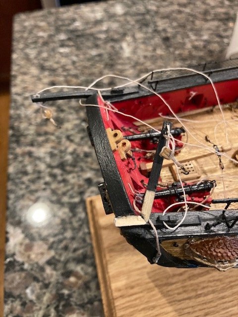
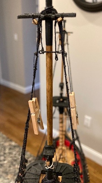
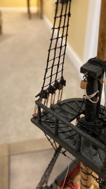
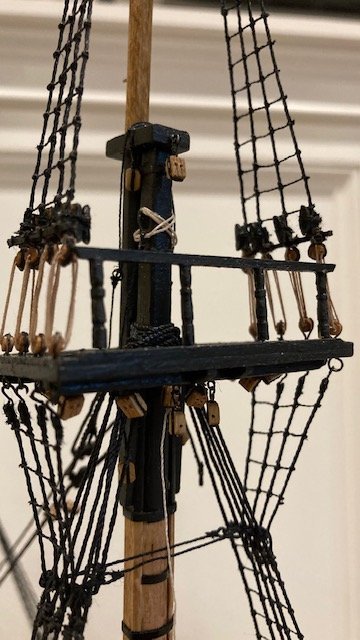
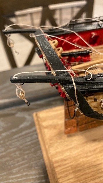
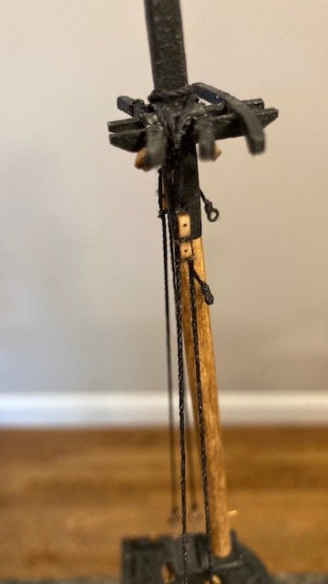
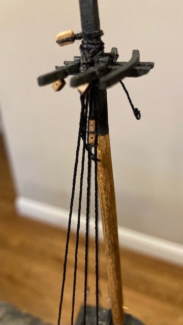
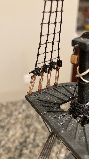
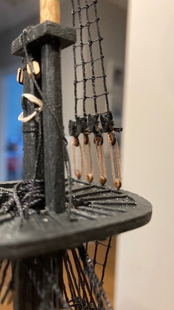
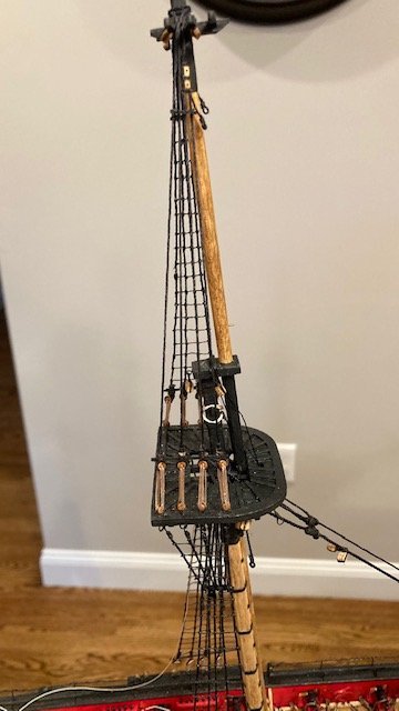
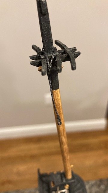
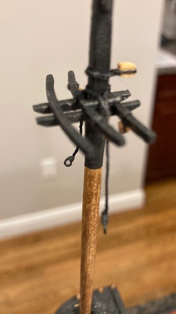
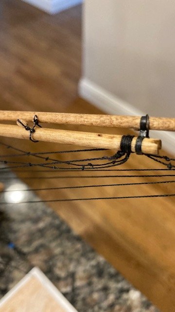
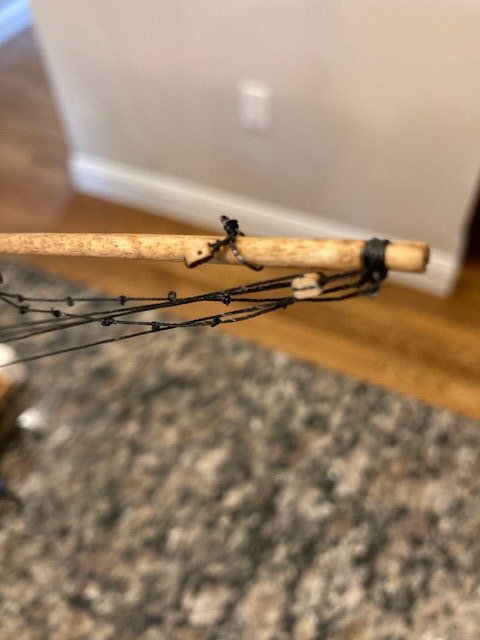
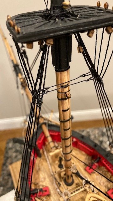
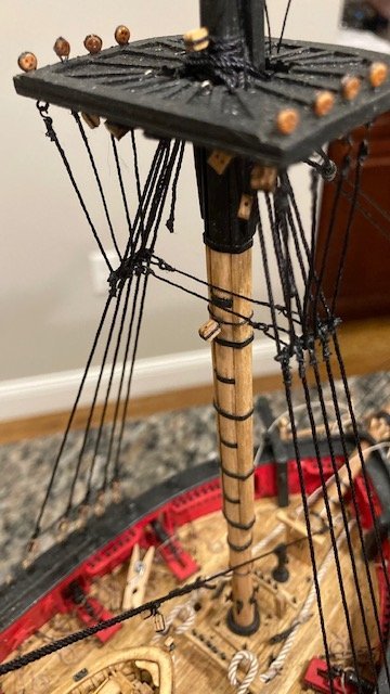
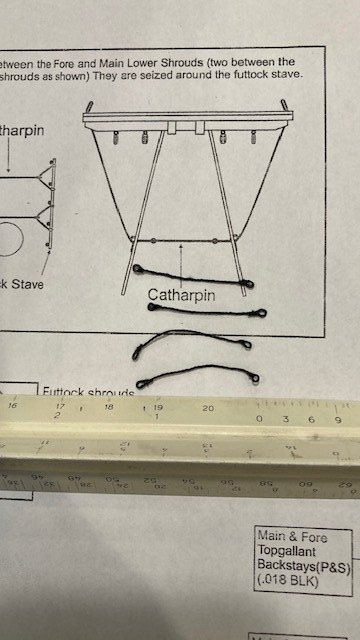
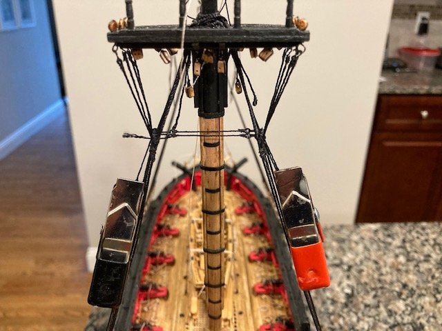
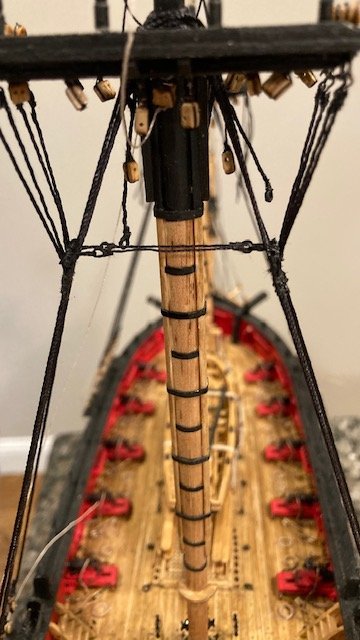
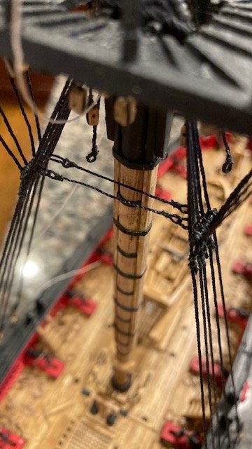
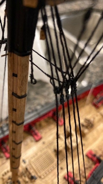
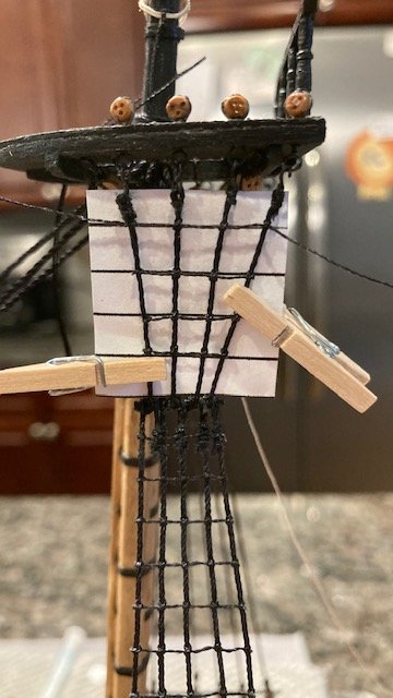
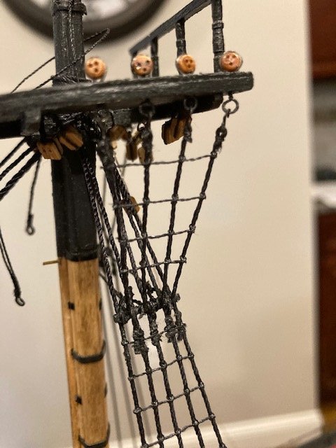
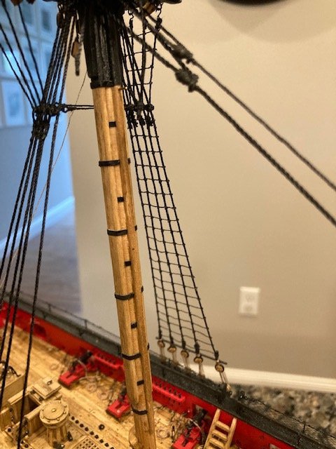
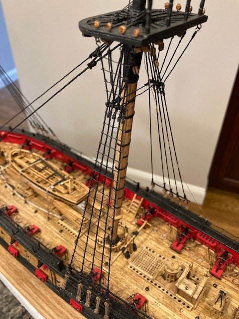
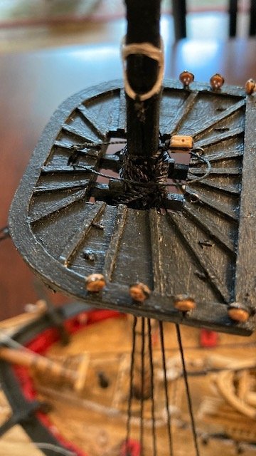
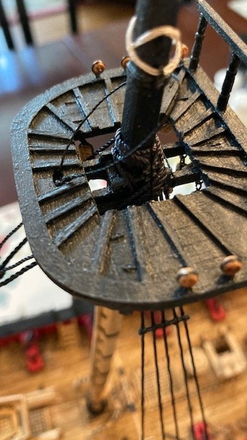
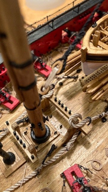
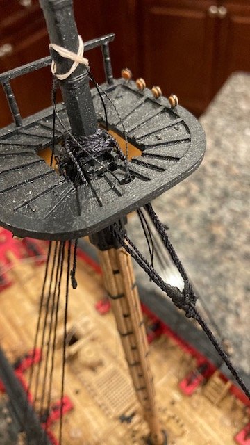
Completed the main topmast shroud rat lines, cleats, the single upper catharpins. I got a little overzealous and broke the starboard side davit. It was an easy fix though -just a little white glue. I made up the cartharpins (.021 black) basically the same as the lower cartharpins (See April 9 post on Page 4) except that I used small clothes pins instead of metal clips to hold the tie lines. This is where you see if the futtock staves are set at the same elevation. My fore top mast staves were a little off. Looking head on, the catharpin was not level (see photo). So, I decided to redo the starboard side stave (see photo) - still not perfect, but much better. Here are photos of the completed main topmast shrouds. Now it’s on to main topmast backstays. But first I need to order more 2.5mm deadeyes.
- 157 replies
-
- 2
-

-
- model shipways
- syren
- (and 1 more)
-
Keep up the good work. I found rigging the carronades a particularly arduous task. I lessened the task by eliminating the upper tackles - after I had completed one carronade I didn't like the look of the upper tackles because the blocks were too close together. I had already made up the blocks and didn't want to re-do them, so I decided to eliminate them all together. It's not authentic, but I'm satisfied with my decision.
-
FYI, It looks like your main topgallant mast is missing a single block for the topgallant bunt line. The plan of the fore and main topgallant mast/pole on Sheet 5 doesn’t show all of the blocks. I discovered there are three (3) 3/32” single bocks on the main topgallant mast (2 for the lifts and 1 for the topgallant bunt line).
-
Yeah, I use them also - they give a niece close cut. A good alternative to nail clippers. Ship is looking good!
-
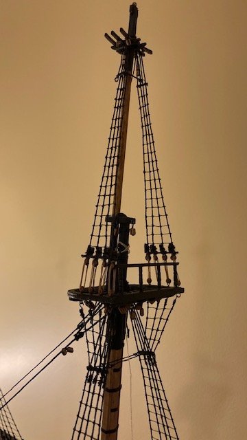
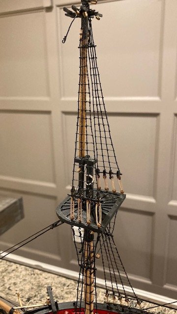
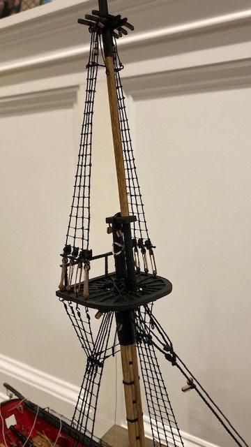
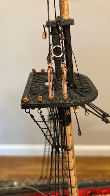
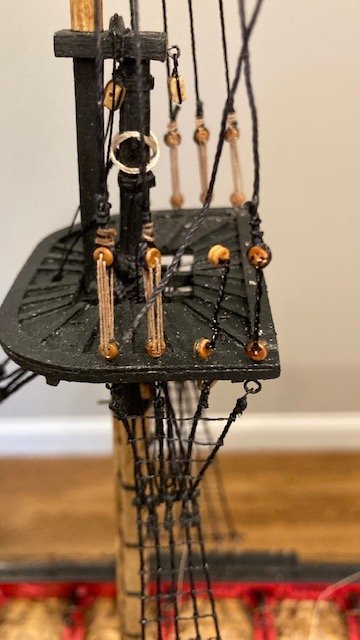
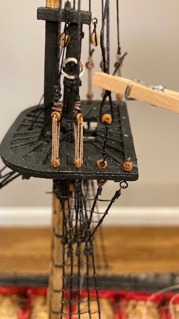
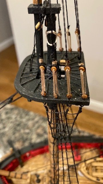
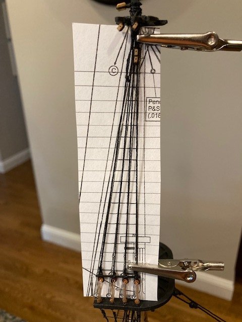
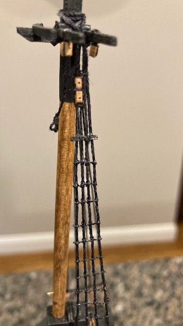
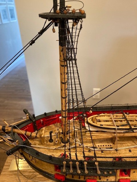
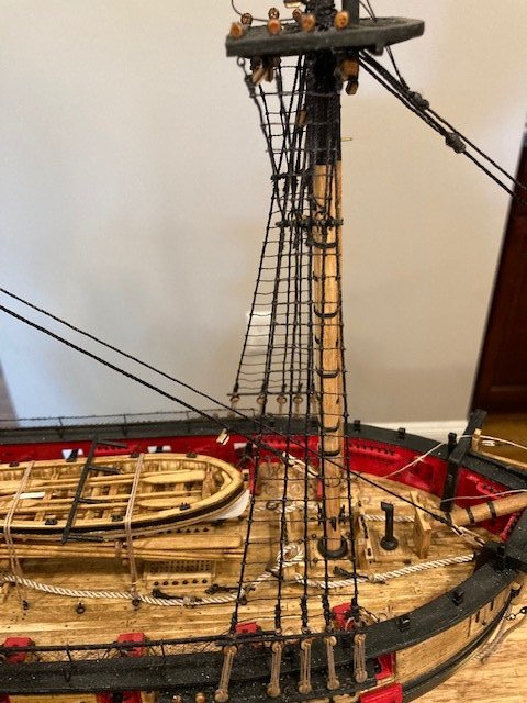
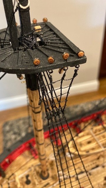
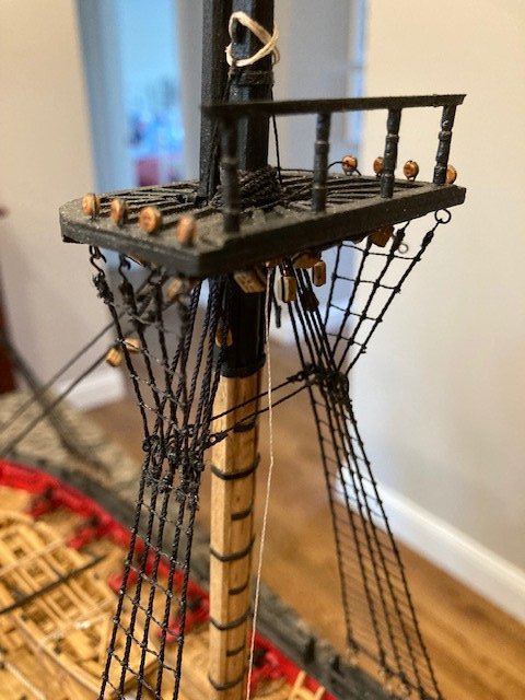
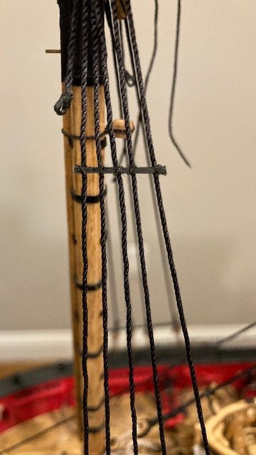
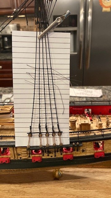
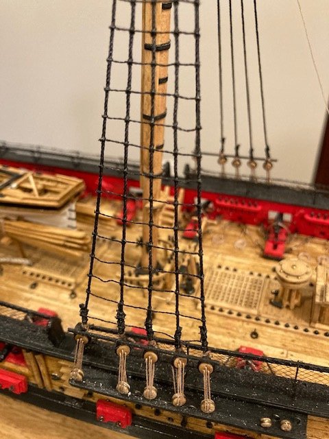
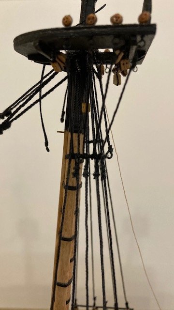
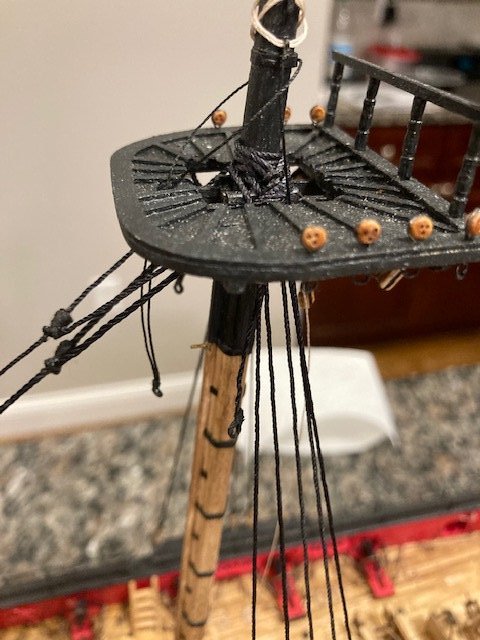
Completed the main topmast shrouds (.021 blk). I found them particularly difficult. To get the pair of 2.5mm deadeyes at the ends of the shrouds reasonably equal requires the use of a “deadeye claw.” I found it difficult to hold the deadseyes on the claw. I used alligator clips for this. Starting on the starboard side, I rigged the shrouds in alternating pairs as per the instructions. I cut a 13” length of .021 line for each pair. I looped each line and seized it with .012 black line about 5/8” below the loop. This allowed for the line to be placed over the cheek blocks on the top of the mast. The spacing between the deadeyes on the topmast shrouds is the same is the lower shrouds, so I used the same deadeye claw. These are tricky because they’re so small. I looped the line around the deadeye, held it in-place with a small clothes pin, and applied a little CA with a toothpick to hold the deadeye in-place, making sure the holes are in the proper orientation. This allowed for the line be seized without the deadeye falling off. I removed the shroud and seized the deadeye off-ship. The second deadeye was setup in the same manner. I setup the port side shrouds in the same way. The lanyards were rigged with Syren .008 light brown rigging line (a 6” length is about right for reeving through the deadeyes and the hitches around the shroud). I made three (3) clove hitches - the clove hitches look nice but they’ll be covered up by the sheer pole. I removed the fore top rail to facilitate the shrouds. Before completing the shrouds and adding the futtocks stave, I added the Sister Blocks (two 3/32” single blocks glued together, end-to-end) between the first pair of shrouds. I located the top of the blocks 1/4” below the cross trees as scaled on Sheet 5, which places them higher than they appear in the photo on Page 102 of the instructions. The instructions say they are placed just above the futtock stave. The futtocks stave would be about ½” below the top of the sister blocks. Completed the main topmast shrouds – phew. I ran out of Syren .008 tan rope for the lanyards. Syren ran out of tan rope, so I had to use the kit supplied .008 manila hemp. The difference in color is noticeable now but overtime, as the model ages., may not be noticeable. Added the top mast sheer pole and futtock stave (1/32” x 1/32” strip). I painted them first, glued them to the shrouds, lashed them with sewing thread, and touched up the paint. The topmast rat lines (.008 blk) were done next and similar to the lower mast. I made a copy of the fore top mast shrouds from plan Sheet 5 and placed it behind the shrouds to see how it lined up. I was surprised how closely the alignment of the shrouds matched the plan (see photo). Decided to buy some 5mm cleats from the Syren Model Co. rather than of using the kit supplied metal cleats. I shaped them to resemble the kit supplied cleats, painted them black, glued them to the shrouds above the sheer poles, and lashed them with sewing thread. I used white glue to adhere the cleats to the shrouds. The Syren cleats have a groove in the center of them that makes it easy to lash them to the shrouds. I wrapped the sewing thread around the cleat, tied it, wrapped it around again, tied it, glued it, and trimmed it. I’ve completed the port side aft shrouds.
-
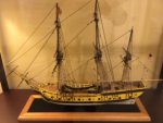
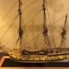
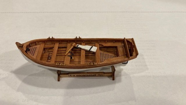
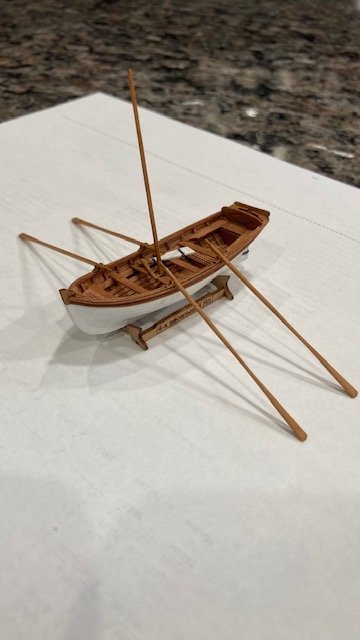
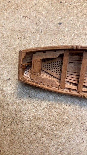
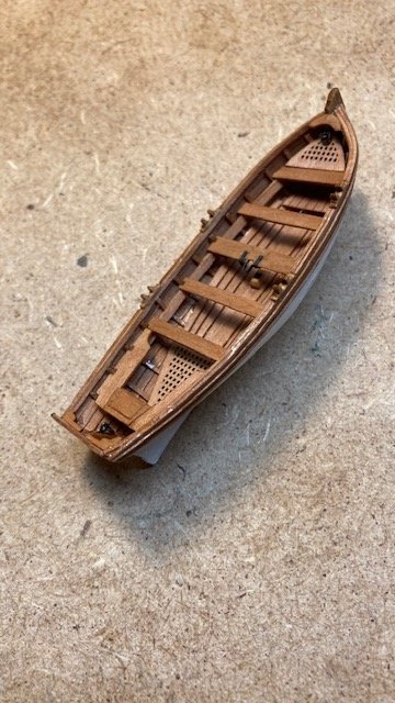
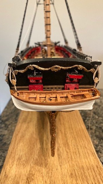
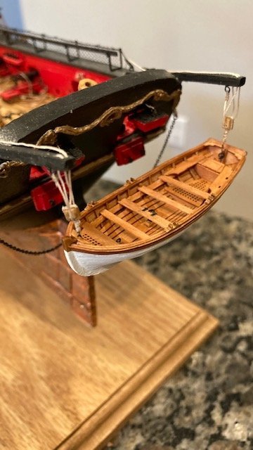
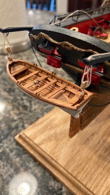
Finished the jolly boat. Added the backboard, rudder, tiller, gudgeons and pintles, mast and oars. The gudgeons and pintles were difficult because they are so small. The oars are delicate and require a lot of sanding. I plan to leave it off ship for now. With that done, I’m moving on to main top mast shrouds. Stay tuned for progress.
.jpg.b227d8ee520d34dd289218432f2f9691.jpg)
.jpg.00b59c4a1b59ce7d943d779327c2b85f.jpg)
- 157 replies
-
- 4
-
-
- model shipways
- syren
- (and 1 more)
-
Thank you, Patrick.
-
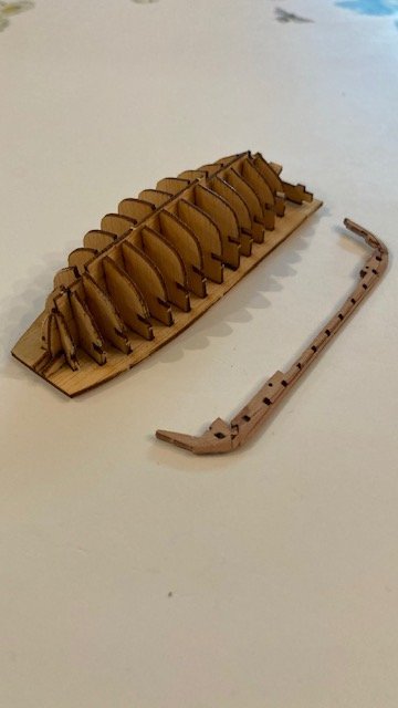
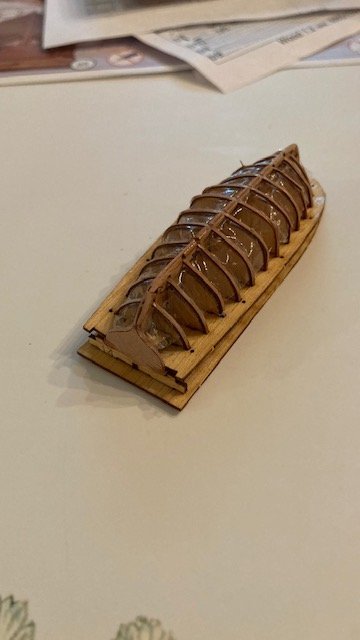
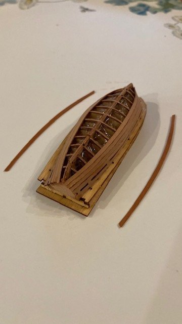
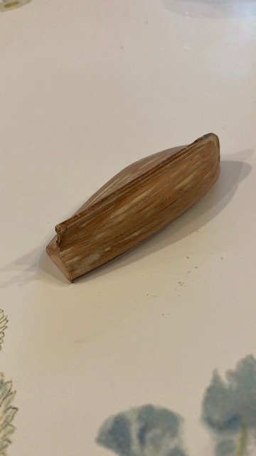
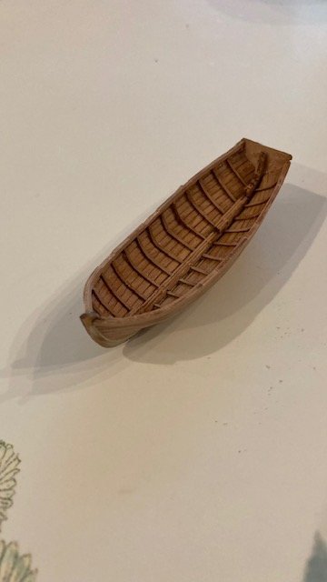
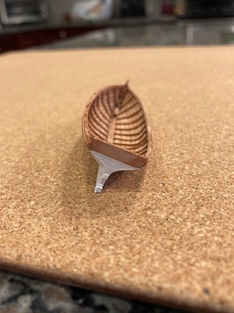
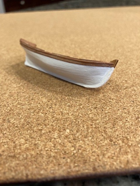
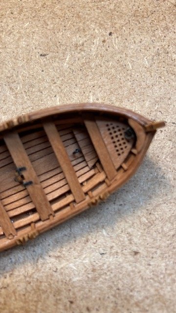
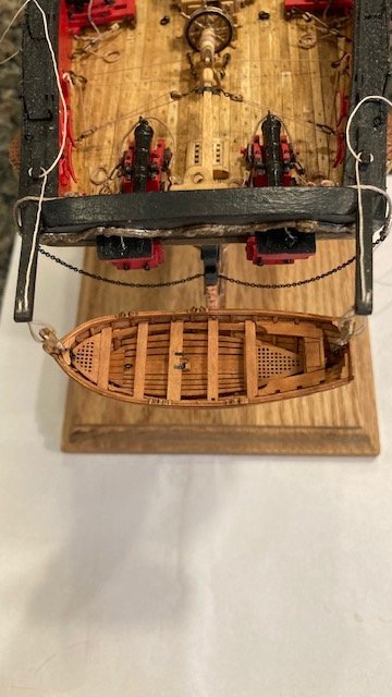
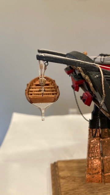
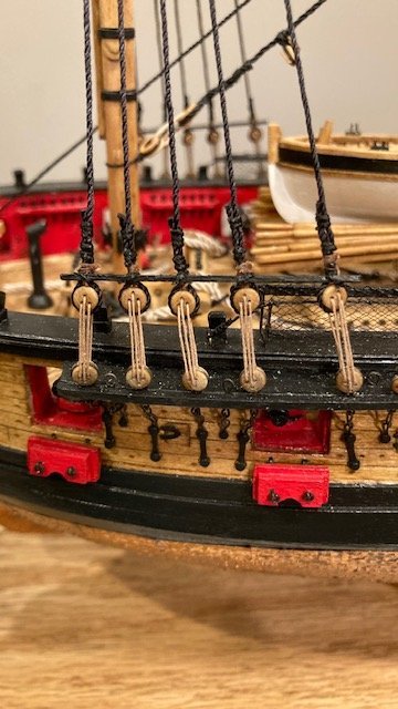
Completed the lower shroud rat lines. All and all, I’m happy with the way they turned out. I decided to build a jolly boat that I purchased from Crafty Sailor. The scale of the kit is 1:72 (1/16” scale). The kit jolly boat is 2 3/4” long (14 ½’ at 1/16th scale). At the Syren scale of 1:64, the jolly boat would be 3 3/32” (16 1/2’ at 3/16” scale). To the novice eye, the difference won’t be noticeable. So, a little shorter boat is okay with me – I’m not looking for authenticity here. If you buy this kit, you’ll need to read the instructions very carefully as they’re a little confusing. The kit comes with 3 laser cut sheets (1 pear and 2 plywood). It’s very important to soak the ribs at least overnight in order to bend them. After installing each rib, I wiped a little water on it with my finger and then dried it with a hair dryer. I’m satisfied with the way they turned out. The transom piece was beveled to the engraved line and then glued to the keel frame. The planking boards were next. They’re numbered successively on the laser cut plan sheet from a7 to a13 and marked R (starboard side) and L (port side). The ends of each plank (except for the last plank a13) are beveled and the burrs are sanded smooth before soaking them. Note: the laser cut (taper) should be installed face down to reduce the width of the joints. The planks are alternated port and starboard or starboard and port depending on your preference. Installing the planks is tricky. I started at the keel and worked back to the transom, applying CA to each rip one at a time. Once completed, the planks were sanded, wood filler was applied to fill in the joints, and finish sanded. Next, I removed the jig with no problem. With that done, I assembled the keel pieces and glued the complete keel to the boat. This was a little tricky – a lot the sanding to get the proper profile to fit the keel. The boat looks surprisingly good, but small. Added the “shoulders” to the hull as per the instructions. They are very thin. I soaked them, fit them on the hull, and held them in-place with small clothespins while I glued them. I applied a little CA on the underside of the shoulders with a toothpick. Before installing the boat interior trim, I primed the hull below the shoulder and later brushed on two (2) coats of finish white paint (ModelExpo MS4831). I wasn’t sure how to finish the interior of the boat. I have read where other modelers have used tung oil, so I decided to try it. I like the finish, but the contrast in color between the pear wood and boxwood wood is quite obvious. Completed the rest of the interior trim (see photos for progression) and applied tung oil. Note: I pre-fit the stern benches, glued them together, and then installed them as a complete unit. The breast hook broke while I was beveling it, so I had to fabricate a new breast hook. It’s not identical but it fills the void, so to speak. Added ringbolts fore and aft to hang the jolly boat. I Made up the double block tackles for the davits. I used 3.0mm blocks and .012 tan line. I drilled a hole on the underside of each davit for an eyebolt. I seized a generous length .012 line to each eyebolt and then glued each one in the predrilled hole. I then reeved the line through the blocks and the davit sheaves. I’m thinking, given the high seas, that the jolly boat would have been more secured than just hanging it from a hook – just my thoughts. Remaining bits are the backboard, rudder, tiller, gudgeons, pintles, mast, and oars. It was a good exercise in a miniature side build.
.jpg.e27ad07814f69a66c826ca925fac2866.jpg)
.jpg.b401922932a55d924042af2aaecb778c.jpg)
- 157 replies
-
- 4
-
-
- model shipways
- syren
- (and 1 more)
-
Love the barrel and bucket - nice added touch.
-
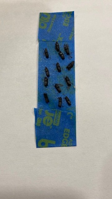
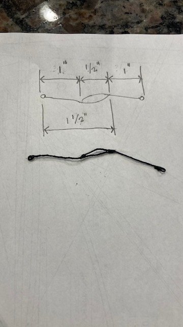
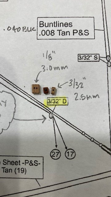
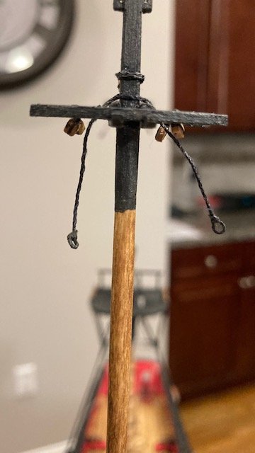
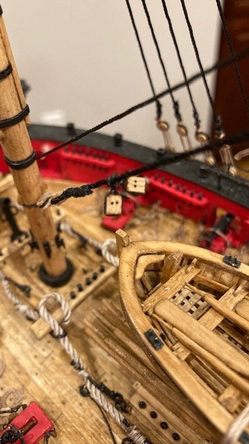
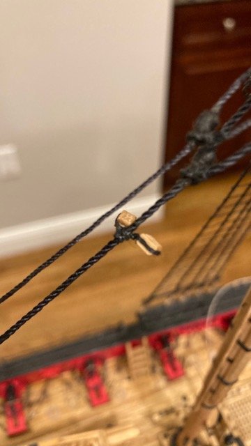
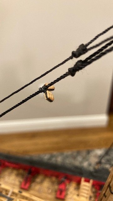
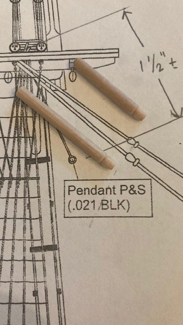
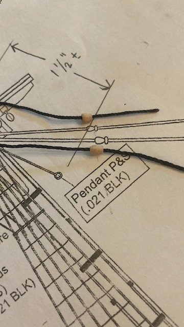
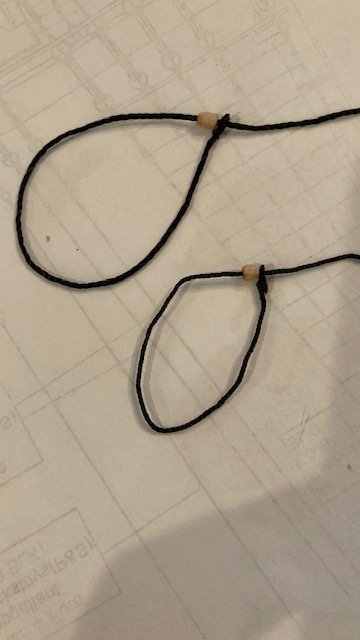
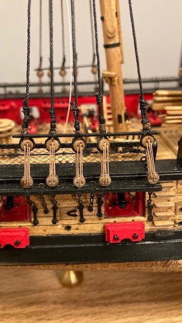
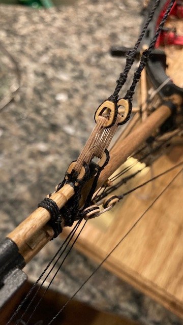
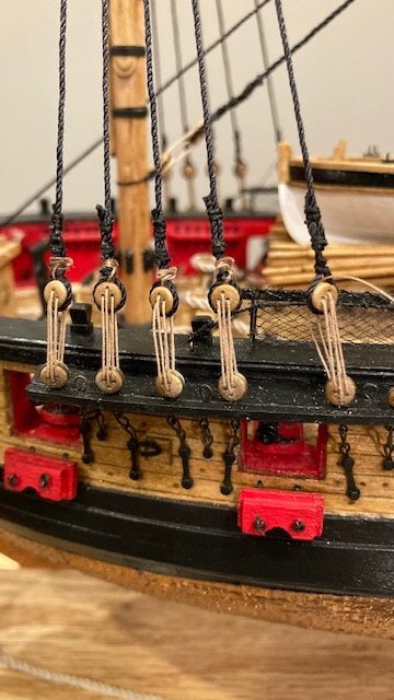
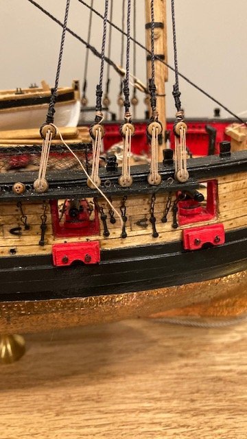
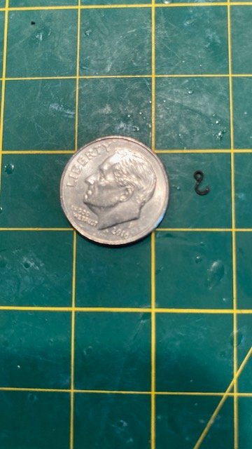
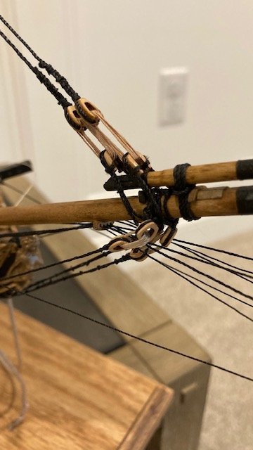
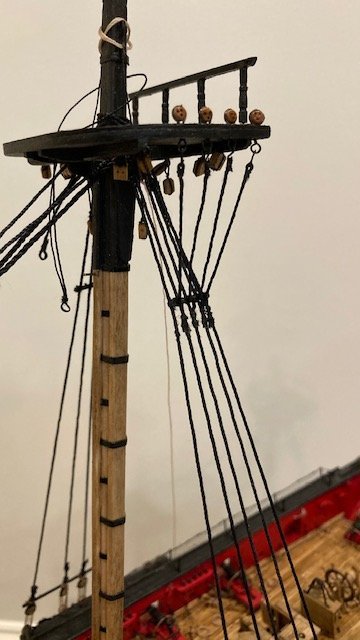
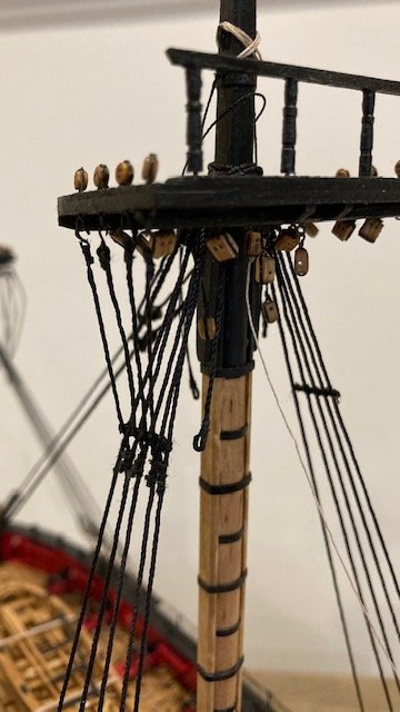
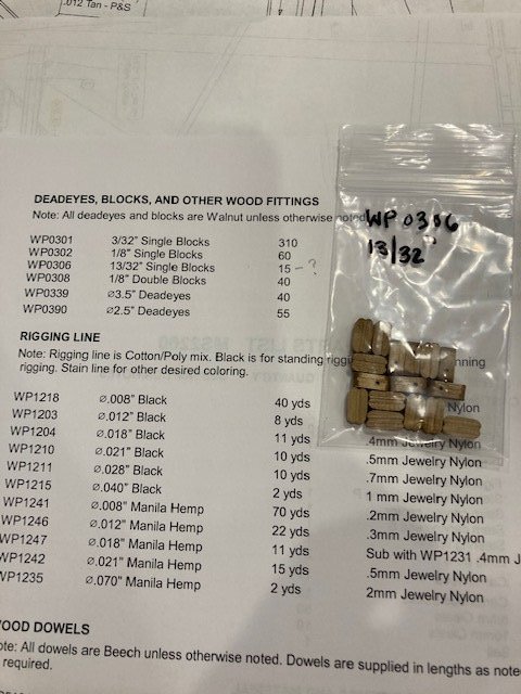
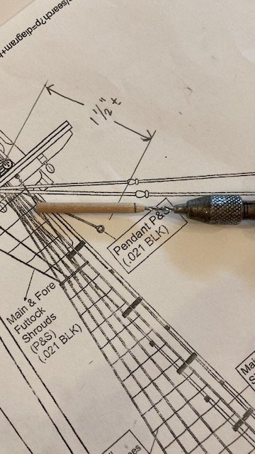
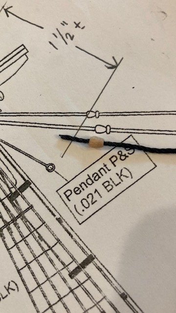
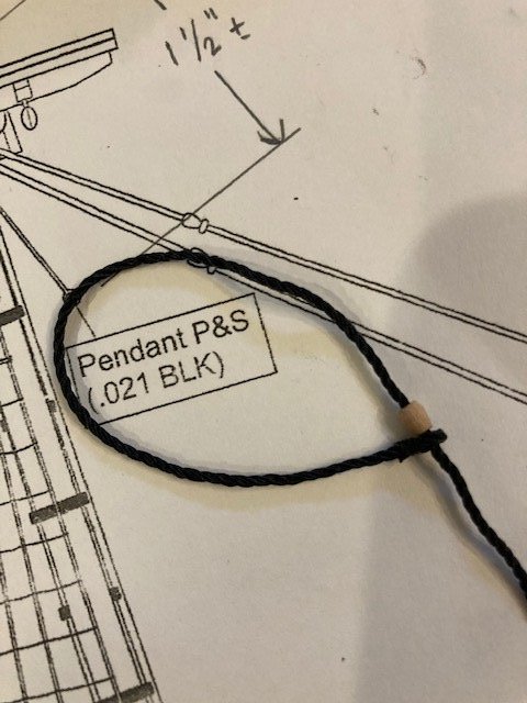
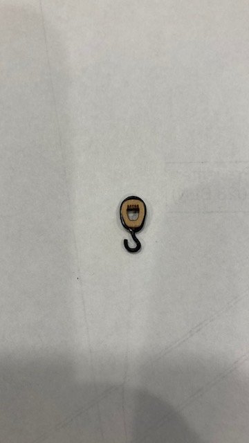
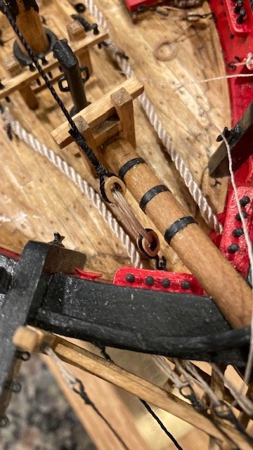
While still waiting for my Model Expo order, I decided to make the main topmast pendants. These were made from .018 black line. Starting with the fore top mast, I made an eye at the end of the line by wrapping the line around a rounded needle nose plier, applying a little CA, and then seizing the line with black thread. To get an approximation of the length of line, I scaled the length of the pendent below the top (3/4") and added 3/4" to fit over the cheeks on top of the mast. I then cut the line at an angle 1 ½” long. The cut ends of the two pendants were then glued and seized to the respective lines at a distance of 1” from the eye. The eyes were painted black. After installing the pendants, I attached a clip to the end of each pendant to stretch them out. Note: With the method I used to make the pendants, I had to remove the 1/8” single block for the main top gallant stay in order to install the pendants. No problem though, as I was able to re-rig the 1/8” block with the top mast off ship. One dilemma though. I finally received my Model Expo order. The order included four (4) 1/8” (3.0mm) double blocks instead of 3/32” (2.5mm) double blocks. I decided to order Falkonet 2.5mm blocks from Model Expo. These blocks match the scale of the 3/32” D block shown on Plan Sheet 7. They are very small and need to be drilled out in order to reeve the .012 line for the top braces through them. I reviewed some other build logs to see what size blocks were used. I found photos but no discussion on this. But, based on the photos are saw it appears that other build logs have used blocks larger than 3/32”. FYI, there is a discrepancy in the pictorial size of the main stay blocks on Sheet 7. The upper D blocks are depicted larger than the lower D blocks – they’re both noted as 3/32”. The upper D block near the mouse appears to be 1/8”. For comparison purposes, I superimposed a 1/8” D block, a Falkonet 3/32” D block, and a 3/32” S block on Sheet 7 (see photos). The 3/32” Falkonet block appears to be slightly smaller than the 3/32” S block. So, the dilemma is, what size block to use. I might be over analyzing this, but I think the 3/32” blocks are too small for the .012 rigging line, so I will use the 1/8” D blocks. Accomplished my goal of installing the 1/8” double blocks for the Fore Top Sail Braces and the Fore Braces. To the novice eye, I don’t think the larger blocks will be noticeable. The process was simple – seized some .012 black line to each block, tied the loose ends to the main stay with an overhand knot, applied CA to the knot, trimmed the ends, and painted the knots black. Thought this would be a good time to add 3/32” S blocks to the traveler rings on the jib boom. These were set up in the same manner as the 1/8” D blocks above. Lashed the sheer poles and the futtocks staves to the fore lower yards. I used sewing thread to lash the futtocks staves. Next, the futtock shrouds were wrapped around the futtocks stave a la the main shrouds. The fore lower catharpins were rigged same as the main lower catharpins. Note without incident though. Murphy’s Law reared its head again – I got a little overzealous in tensioning the catharpin and the futtocks stave snapped. I was able reset it with some CA glue – catastrophe averted. Whew. Next up, the fore lower shroud rat lines. Stay tuned.
.jpg.09be699cdca5d6f37b19a758d87eefce.jpg)
.jpg.71c0fcf19827a1897a5b152dcb0f17e6.jpg)
.jpg.a22b63b92cfb3d690b9226ae8d4bb70a.jpg)
- 157 replies
-
- 4
-
-
- model shipways
- syren
- (and 1 more)
-
Very nice! Good luck with shoulder surgery.
-
You've taken the sagging of the breech lines to the nth degree. They look good.
- 436 replies
-
- 1
-
-
- Syren
- Model Shipways
- (and 1 more)
-
I used Syren tan .025” brown rigging line for the breech ropes and .008” for the seizing. I have been unable to order from the Syren website lately. I think I read somewhere where they're going our of business????
- 436 replies
-
- 1
-
-
- Syren
- Model Shipways
- (and 1 more)
-
Excellent work on the quarter badges. You obviously can see three dimensionally - not everyone can.
-
Nice work. Progressing well. For the gun ports, did you use the pieces cut from the bent planks? Did you plank over the ports and then cut them out?
-
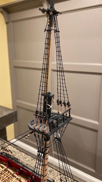
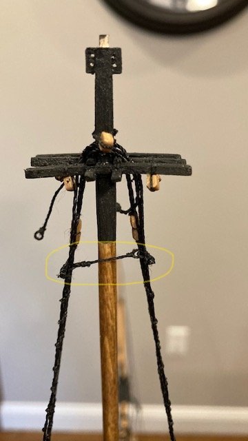
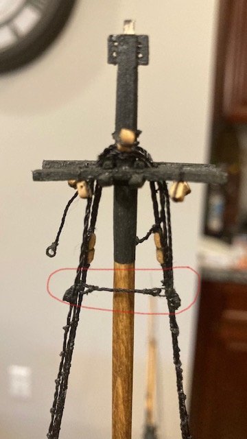
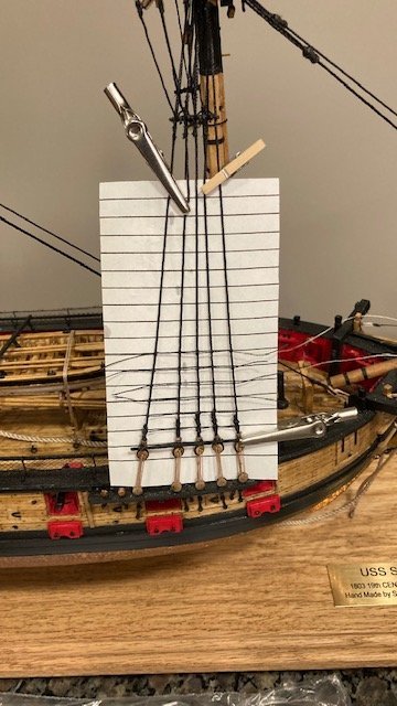
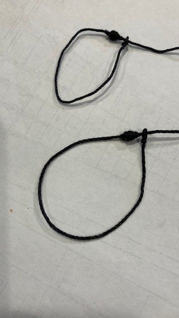
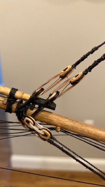
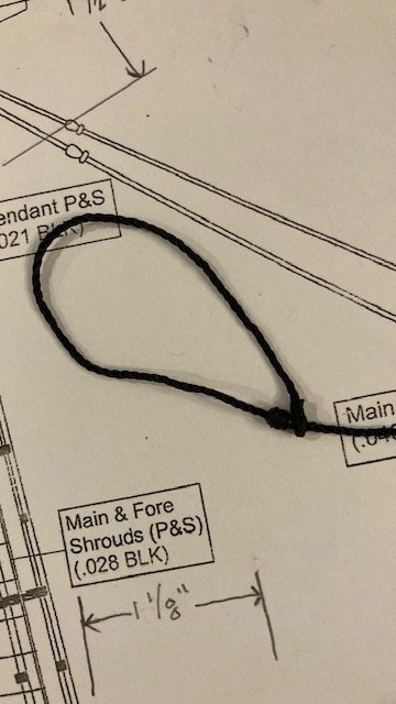
Finished the starboard side shrouds. For the catharpins, I followed WalrusGuy’s build where the catharpins are lashed in two parts to the shrouds. I made the first part of the catharpins from .018 black line made with an eye splice at each end and 1 1/8” long. Note: I realized later, after looking at the detail on Sheet 5, that the catharpins should be shorter (about ¾”) - it’s important to look at the plan sheets as well as the instructions. The second part consists of short lengths of .018 black line reeved through the eye splice and tied around the stave at each end as shown on Sheet 5. The first part was easy. The second part was difficult because of the need to adjust the lengths of the tie lines to center and tension the eye spliced line. I set up the ties port and starboard, secured one loose end with CA, reeved the other loose end through the eye, wrapped it around the stave and attached a clip to it (see photo). Then, I adjusted the clips to center the eye splice line, secured one tie with CA, and then tensioned the line by pulling on the loose end of the other tie and securing it with CA. The loose ends were trimmed. After a couple of failed attempts, I successfully completed the cartharpins. I'm satisfied with how they turned out, although one has a little kink in the line (from CA glue). I hope the lower fore main cartharpins will be easier. I’m still waiting for 3/32” double blocks for the main stay. Model Expo sent 3/16” single blocks instead of 3/32” double blocks. In the meantime, I decided to begin “rattling down” the lower shrouds. I used the prototypical card with lines on it to help evenly space and level the rat lines. I spaced the lines at a ¼” (0.22 row spacing on an Excel spreadsheet). The .008 ratlines were tied using clove hitches, except for the first shroud where an overhead knot was used – found it easier to secure the line this way. This is definitely tedious work – patience is a virtue here. I found the process easier as you move up the shrouds. I applied CA to each clove hitch and touched them up with some diluted black paint. So far, I’ve completed the port side lower main shrouds and futtocks shrouds rat lines, but not without incident. While doing the rat lines on the futtock shrouds, the seizing on the aft most shroud came undone at the hook - Murphy's Law. I decided against reconstructing it. I was able to re-seize it. I don't really like the way it turned out, but I'm willing to accept some imperfection here over the aggravation of otherwise having to replace it.
- 157 replies
-
- 2
-
-
- model shipways
- syren
- (and 1 more)
-
Novel idea on the window frames. So far so good.
-
Great innovation on the "multi-cleat pinning jig." And, I share your frustration on items pinging off the tweezer - some of them never to be found.
-
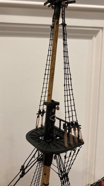
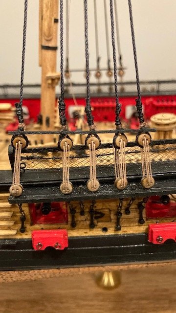
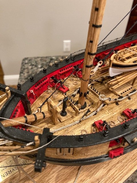
I’m still waiting for the four (4) 2.5 mm (3/32”) pear wood double blocks from Model Expo. I wanted to seize them to the main stay before adding the fore lower shrouds but that’s not going to happen. In the meantime, I completed the first pair of shrouds on the starboard side and one shroud on the port side. I had to order more 3.5mm deadeyes. The kit comes with the exact number needed for the lower shrouds. I lost or misplaced 4 deadeyes. While waiting for the deadeyes, I decided to make the mouse for the fore stay and fore preventer stay same as the main stay and main preventer stay. I measured the length of .04 and .028 black line required for the stays using Sheet 7 and cut each length 13”, allowing for wrap around the mast head, the 5mm closed heart, and making the eyebolt. I set up each stay and determined where the mouse needs to be positioned and applied CA to secure it. I painted each mouse black and finished them by seizing with black thread. I’ll put this aside until I finish the fore lower shrouds. My Model Expo order arrived, so it’s on to the fore lower shrouds again. I completed the first port side pair, the second starboard and port side pairs, and the single shrouds. No problems here. I left the single shroud lanyards loose in case I have to remove them to install the lower double blocks on the main stay. Now, on to setting up the fore stay and fore preventer stay. The fore stay and fore preventer stay were setup with Syren 5mm closed heart (I like the thickness of these hearts over the laser cut ones provided with the kit) seized to the loose end of each stay. The closed hearts were set up with .012 tan lanyards reeved between the hearts and the open hearts on the bowsprit collars added in Chapter 16. This is a big milestone. The rigging is starting to take shape. Now onto the sheer poles and futtock staves. Lashed a 1/32”x 1/32” sheer pole and futtocks stave on the starboard and port side of the main lower shrouds. I painted them black before lashing them. The sheer poles were easier to lash than the staves. The futtock shrouds are next. I seized a hook to one end of each .021 black shroud. The hooks were made from 1/32” brass eyebolts. After seizing the hook, I cut the line to about 2" long. The hooks were attached to the deadeye plates and the loose ends were wrapped around the futtock stave, glued to hold them in-place, seized to the lower shrouds and trimmed. I used black sewing thread for the seizing. So far, I’ve completed the port side futtocks shrouds.
.jpg.79c82f5f69c0a3905d5a0429d30d59b6.jpg)
- 157 replies
-
- 4
-
-
- model shipways
- syren
- (and 1 more)
-
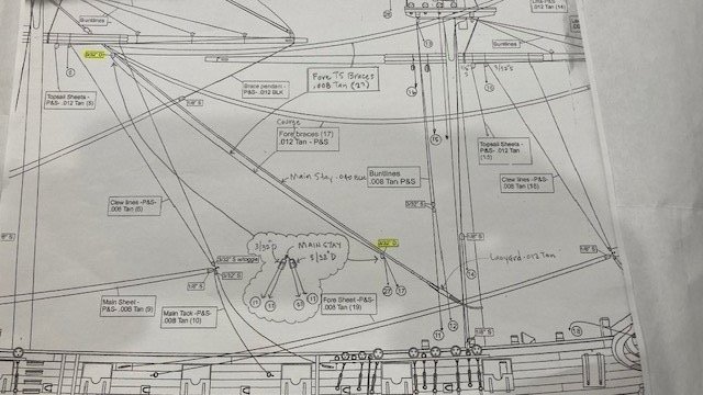
Before starting on the fore lower shrouds, I decided to look at the blocks that need to be attached to the Main Stay. Plan Sheet 7 shows 3/32” D blocks. My Model Shipways kit was not furnished with 3/32” D blocks. Oddly, it was furnished with 13/32” S blocks, which are not noted anywhere on the plan sheets and are otherwise way to big (see photo). Two pairs of 3/23” D blocks are required. Model Shipways offered to provide these. To clarify Sheet 7, I’ve included a latitudinal sketch showing the two (2) 3/32” D blocks that are required at two locations on the main stay. These blocks are for the Fore Top Sail Braces and the Fore Braces. The Fore Top Sail Braces pass (27) through the inside sheaves of the blocks and the Fore Braces (17) pass through the outside sheaves as noted on page 122 of the instruction manual. Will follow up with a photo when I receive the blocks.
- 157 replies
-
- 3
-
-
- model shipways
- syren
- (and 1 more)
-
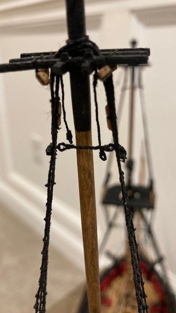
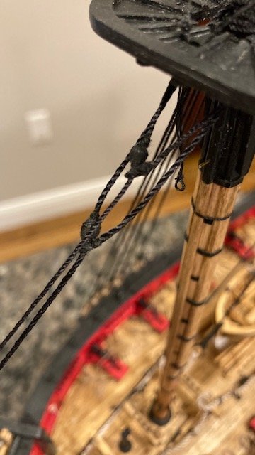
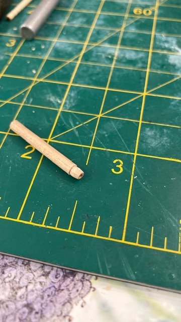
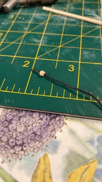
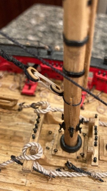
Continuing with Chapter 18, I began the main stay rigging by making the mouse. I followed SalD’s method (excellent idea), i.e., I used a 5/64” diameter dowel and shaped the end in a pencil sharpener. I drilled a hole in the end of dowel with a .55mm bit first and then gradually increased the bit size to accommodate the .04 black main stay line. Then I roughly shaped the end dowel with sandpaper before inserting it into the pencil sharpener to get its basic shape. I measured the length of the mouse from Plan Sheet 5 and marked it in pencil on the dowel. Before cutting off the dowel, I scored the pencil line, removed some of the dowel with a knife and then filed around the score to get the basic shape of the mouse. I then cut off the dowel and finished shaping the mouse. The process is pretty easy. It’s important that the drill hole is centered in the dowel. I applied CA to the end of the main stay line to make it easier to pass it through the mouse. Next, I seized an eye onto one end of the rigging line using sewing thread. I measured the length of the main stay from Sheet 5, allowing extra length for the wrap around the mast head and seizing the 5mm closed heart to the loose end. I set up the main stay around the mast head temporarily to get the distance of the mouse from the mast (about 1 5/8”). I glued the mouse to the main stay and painted it black. I finished the mouse by seizing it with black thread. I passed the loose end of the main stay through the eye and then inserted the line through the Lubbers Hole and looped it around the mast head and on top of the shroud gang - make sure the slings are on the outside of the main stay. As a matter of note, the orientation of the mouse and eye as shown in the photo on Page 96 of the instructions is opposite that shown on Plan Sheet 5. Some build logs have followed the orientation on the photo and some have followed the orientation on Sheet 5. I chose the orientation on Sheet 5 – I guess it’s a matter of preference. I seized a Syren 5mm closed heart to the loose end of the line with black sewing thread. Before I set up the lanyard, I realized that the main stay rigging was inside of the trestle trees rather than on the outside as depicted on Sheet 5 – OOPS! So, I had to remove the closed heart and re-thread the line so that it is on the outside of the trestle trees – PHEW! With that done, I reeved the .012 tan lanyard between the main stay heart and the heart rigged on the foremast. I reeved the line 4 times around the hearts. I tied off the first reeve at the main stay heart. I didn’t tie off the last reeve; just applied CA to it on the back side of the main stay heart. Next, the main preventer stay. I made the mouse in the same manner as the main stay. I measured the length of the main preventer stay from Sheet 5, allowing extra length for the wrap around the mast head and seizing the 5mm closed heart to the loose end (about 17”). I set up the main preventer main stay around the mast head in the same manner as the main stay, making sure the line was on the outside of the trestle trees. I seized a Syren 5mm closed heart to the loose end of the main preventer stay. I had previously glued the eyebolt for the main preventer stay heart that is secured to the deck. I didn’t want to remove the eyebolt in order to seize the heart to it, so I decided to make a hook on the end of the 5mm closed heart using 22 gauge wire. The eyebolt is in a confined space, so rather than hook the heart to the eyebolt and then set up the lanyard, I found it easier to set up the lanyard with the hooked heart off ship and then hook the heart to the eyebolt. This worked well. I was able to adjust the reeves to tighten the stay. So far so good. Now on to the fore lower shrouds. Stay tuned for update.

- 157 replies
-
- 1
-
-
- model shipways
- syren
- (and 1 more)
-
Good choice on the tung oil.

