
HOLIDAY DONATION DRIVE - SUPPORT MSW - DO YOUR PART TO KEEP THIS GREAT FORUM GOING! (Only 24 donations so far out of 49,000 members - C'mon guys!)
×

abelson
-
Posts
467 -
Joined
-
Last visited
Content Type
Profiles
Forums
Gallery
Events
Everything posted by abelson
-
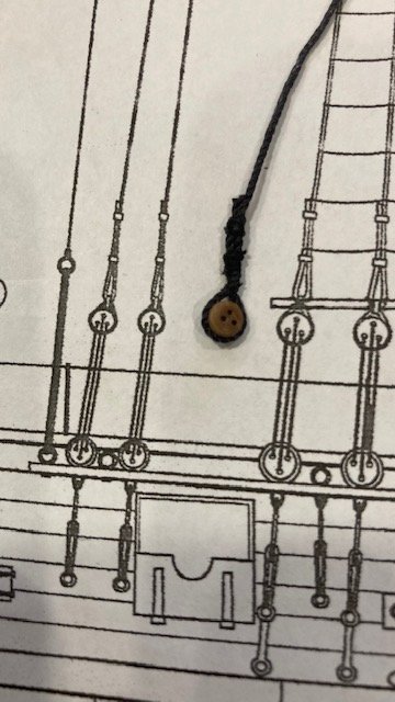
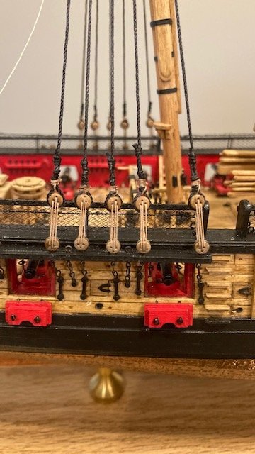
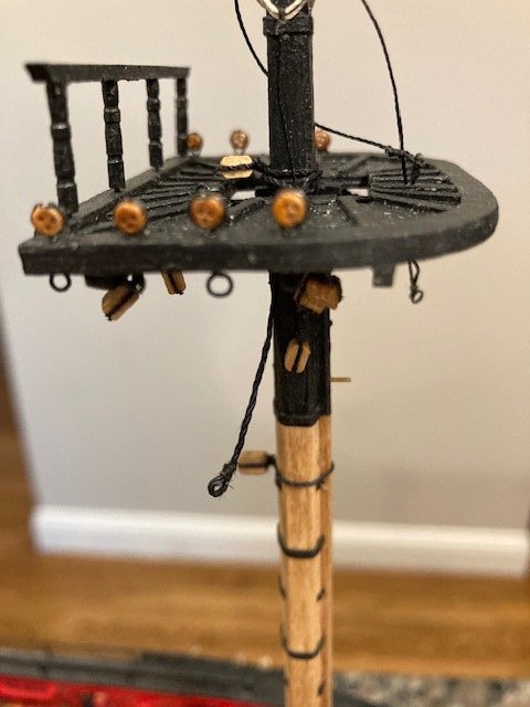
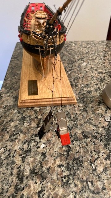
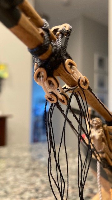
 Began rigging the shrouds as per the instructions. To get the distance between the deadeyes I used a "deadeye claw" made from 20 gauge wire. I cut two lengths of wire, twisted them around each other, separated the end wires, bent the wires on one end, matched the bent ends with the deadeye plan on Sheet 5, and then bent the opposite end wires at the corresponding deadeye. I applied CA to “solder” the twists. Using Sheet 5 as a guide and allowing for wrap around the mast and the dead eye, I cut two lengths (about 18”) of .028 black line for the fore most starboard and portside main mast shrouds. I looped each line and seized it with .012 black line about ½” below the loop. The shrouds were looped over the main mast and passed through Lubbers Hole. Note: I believe the jeer lines are outside the shrouds, so, if you install the jeer lines ahead of the shrouds as I did, the jeer line must be passed through each shroud loop so that it is on the outside of the shrouds – in hindsight, I would have installed the jeers after completing the shrouds. With the claw in-place, I setup the first pair of shrouds on the starboard side, seized the deadeyes with .012 black line, and made the lanyards with Syren .008 light brown rigging line following the illustration in the instructions, except that I only made three lanyard hitches. Some of the perfection in the lanyard hitches will be covered by the sheer poles. For me, the difficult part of rigging the shrouds was seizing the deadeyes at the end of the shrouds. I setup the port side pair of shrouds in the same manner. I repeated the procedure for next pair of shrouds. Even with the claw, there are some deviations in the lengths of the lanyards. The perfectionist in me made me redo some of the shrouds. After a couple of failed attempts, I changed my tact. Still cutting an 18” length of .028 black line, I seized the deadeye at one end of the shroud off ship, setup the lanyard, passed the loose end through the Lubbers Hole, looped it around the mast, passed it through the Lubbe’s Hole, and seized the line at the mast head. I then setup the claw, seized the deadeye on the loose end, and set up the lanyard. This procedure work well for me. To hold the deadeye and shroud in-place, I clipped an allegator clip on the deadeye. Making sure that the deadeye holes were oriented correctly, I applied a little CA glue to the deadeye and shroud and removed the clip. This made it easier to seize the line. There are still some deviations in the lengths of the lanyards. There not perfect, but I’m willing to accept a little imperfection here. To complete the main lower shrouds, the last shroud was rigged on each side of the ship. I made these shrouds a little longer (11”) to account for lapping over the other shrouds and looping and seizing the line around the mast head. The deadeye and lanyard were rigged in the same manner. Next up, the main stay.
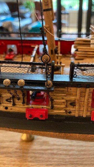
.jpg.7da66d3187ff40a631cb394a48c181a2.jpg)
- 157 replies
-
- 3
-

-
- model shipways
- syren
- (and 1 more)
-
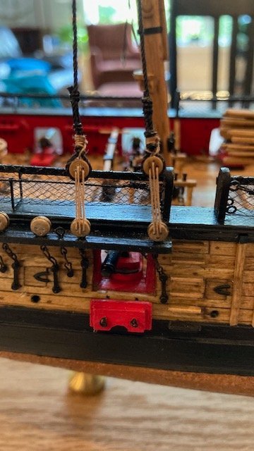
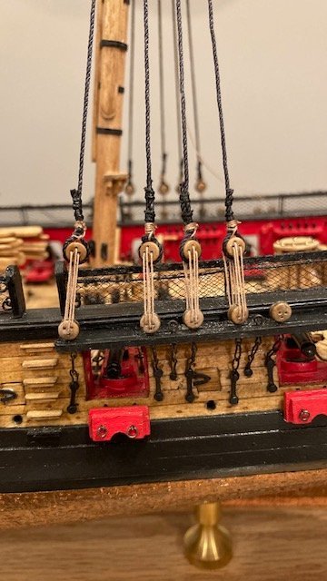
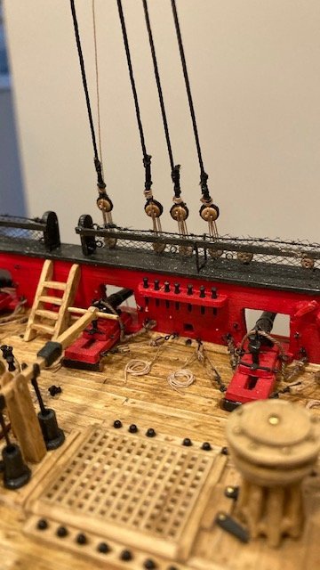
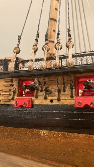
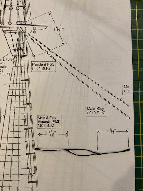
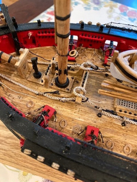
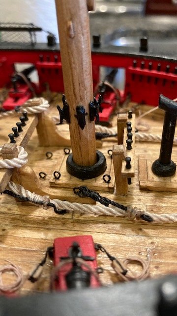
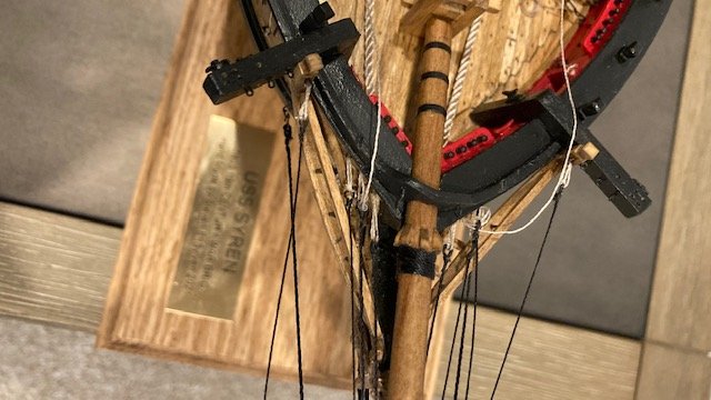
Completed securing the chain plate assemblies to the hull. My concern about the chain plate assemblies hanging below the wale turned out not be a concern at all. The chain plates ended up being shorter than depicted on the plans. I used the kit provided brass pins to secure the chain plates. The pins are too long and need to be cut down. Installing them was quite difficult and frustrating. I decided to follow the alignment/angle of the chain plates shown on the plans rather than rig a temporary shroud from the mast top. I secured the fore and main lower masts. I didn’t do anything special here, just used “yellow” carpenters glue per the instructions, eyeballed it, and held the masts in-place until the glue dried sufficiently for the mast to stand on its own. To get the proper angle for the main mast, I used a piece of cardboard that was cut at the same angle as the plan. I had to insert some wedges to hold the mast at the proper angle. I waited 24-hours before cutting off the wedges. To further secure the masts, I applied CA around the perimeter. The laser cut mast coats were slid down into position. I didn’t coat the coats to simulate canvas and tarring as some other build logs have done. On to the standing rigging. The main and fore mast lower pendants were next. These were made from .021 black line. To get an approximation of the length of line, I scaled the length of the pendent below the top 1.5" and added 1.25" to wrap around the mast. I made an eye in the end of the line by wrapping the line around a rounded needle nose plier, applying a little CA, and then seizing the line with black thread. I then cut the line at an angle 1.5" from the end of the eye. The ends of the two pendants were then glued and seized to the respective lines at a distance of 1 1/8” from the eye. The eyes were painted black. After installing the pendants, I attached a clip to the end of each pendant to stretch them out. The pendants ended up measuring just under 1.5". Credit to WalrusGuy for his build log photos documenting how he made the pendants. Next up, the main lower shrouds
- 157 replies
-
- 5
-
-
- model shipways
- syren
- (and 1 more)
-
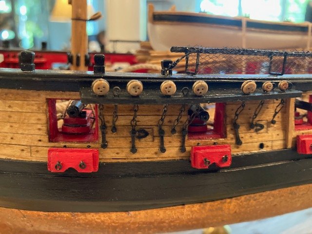
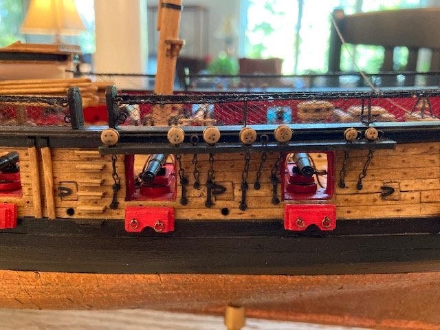
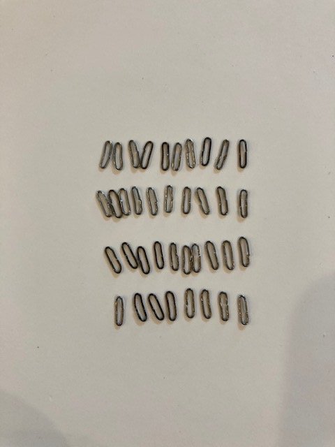
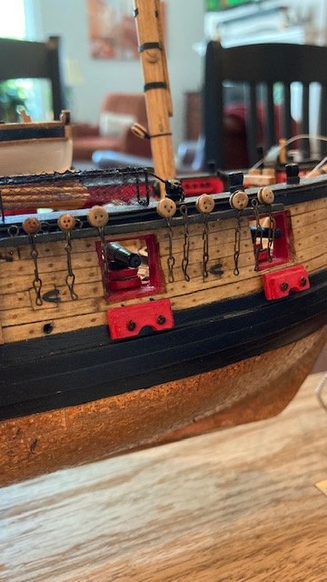
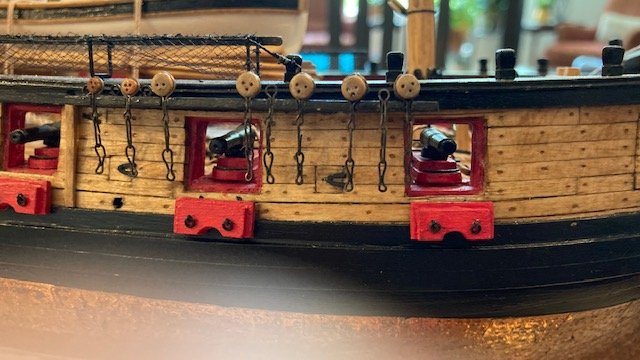
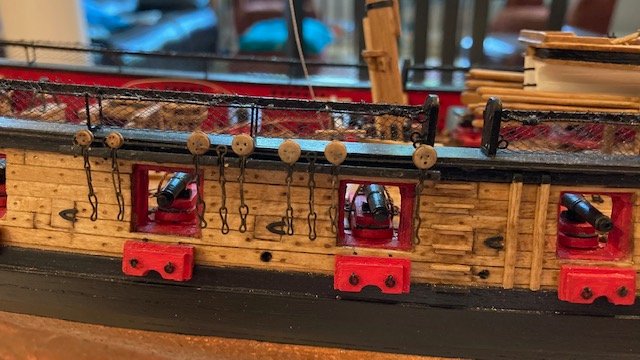
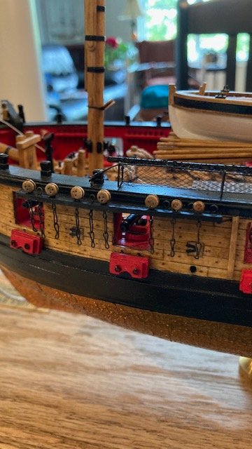
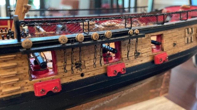
Started Chapter 18 by making the 28 gauge wire deadeye strops for the 2.5 mm (8 required) and 3.5mm (20 required) deadeyes. These were fairly easy to make. I set up a jig as per the instructions. I deviated from the instructions by gluing the deadeye after bending the wire around the deadeye. I found this to be easier, plus I could position the deadeye. I trimmed the excess wire and applied a little CA with a toothpick to secure the wire. I finished it off by filing the cut ends. Next, I made the eight (8) eye bolt links. I set up the jig and followed the instructions, except for one deviation. I crimped the link around the nails before cutting the wire. Cutting the wire after crimping gives is a little difficult but it gives a closer fit between the wires. The middle links (36) and the toe links (36) were next. I had read in some build logs where the chain plate assemblies hang below the wale. To err on the side of caution, I made the links 3/16” instead of 1/4”. I set up the jig and went about making the links as per the instructions. The middle links are easy to make, the toe links not as easy. I decide to use the brass photo etched plate preventer links rather than make them from 28 gauge wire. I blackened all the links and assembled them. I bent the end of the toe links so they will lay flush with the hull when nailed. To position the link assemblies in the notches in the channel and apply CA to secure them I placed the ship on its side. I completed the starboard side first. On the port side I changed my tack (no pun intended). I used white glue to set the assemblies. The assemblies stick to the more gelatinous white glue, making it easy to position them without tipping the ship on its side. After the white glue dried, I applied a little CA to secure the assemblies. Next, I added the 1/16” x 1/16” molding strip along the edge of each channel. I painted the strips on three sides before gluing them to the edge of the channel. I decided to permanently install the bumpkins. Before gluing them in-place, I seized a 1/8” single block to the end of each bumpkin using .008 black line. Note: The instructions in Chapter 20 say to seize a 3/32” single block to the end of the bumpkin for the fore course tack, but Sheet 7 notes the block is 1/8”. Also, I created an eye at the 1/8” block to seize the .008” tan rigging for the fore course tack. This is different than the instructions which call for this line to be seized to the end of the bumpkin behind the block. This mimics Bloemendaal’s build log. The bumpkins were finished off with a simulated iron bracket to hold the bumpkins down on top of the headrail. Making these is tricky because the bumkins aren’t square to the headrail. I tried a strip of copper tape first with no success. I ended up using a scrap strip of brass from the photo etched fittings. it took quite a bit of bending, twisting, and patience to get the proper shape for the brackets. Next up, securing the chain plates to the hull.
.jpg.89f0027996e137e6ac96f584846283f2.jpg)
.jpg.a86769dd74e6bc563182a8bfe4df660a.jpg)
.jpg.6b14266ece2a0ac8951b4973f6defd5c.jpg)
.jpg.b09f774bbf8d3450359f1dd4f9799af7.jpg)
.jpg.6c0379f70968490436c7339125e263ef.jpg)
- 157 replies
-
- 4
-
-
- model shipways
- syren
- (and 1 more)
-
Wow! You're already moving along. No rest for the weary. Good luck. I'll be following.
-
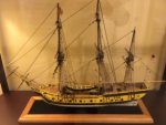
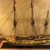
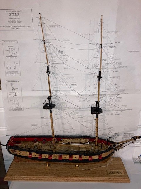
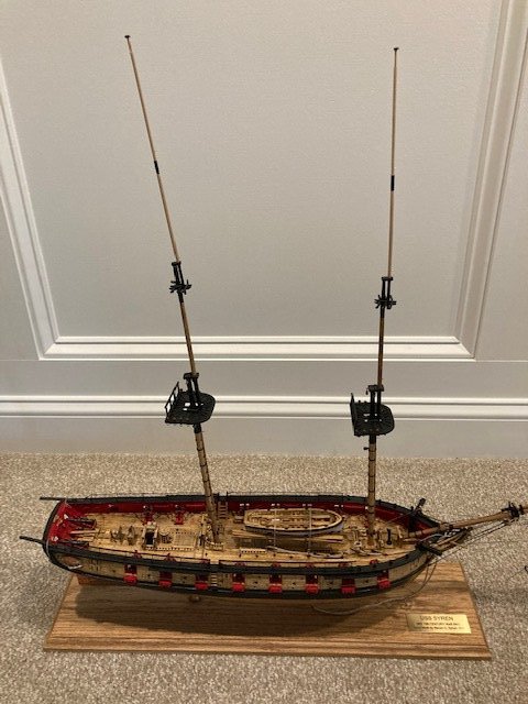
Congratulations! What a fantastic ship model and outstanding photo documentation. Excellent job on the flags - very life like. You definitely have a talent for model ship building - it's your engineering background and visualization and attention to detail.
- 950 replies
-
- 2
-

-
- syren
- model shipways
- (and 1 more)
-
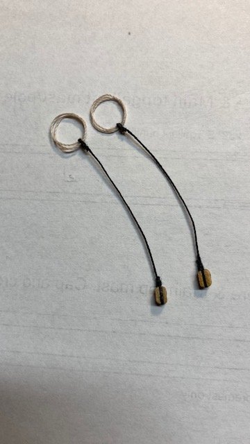
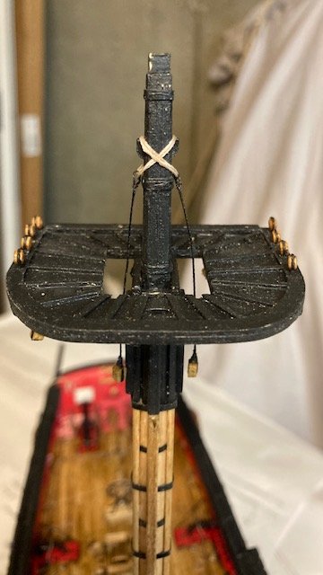
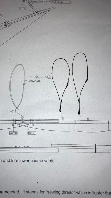
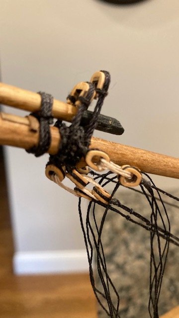
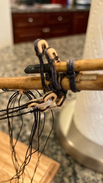
Thanks. I didn't find much discussion on how to make the jeer blocks and slings in other build logs so I thought I would add some. I hope it's helpful.
-
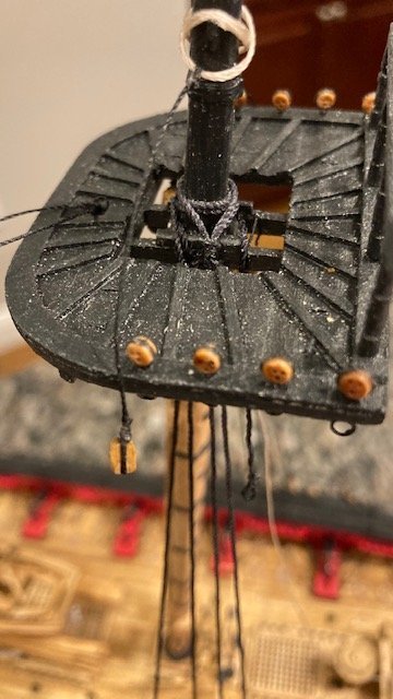
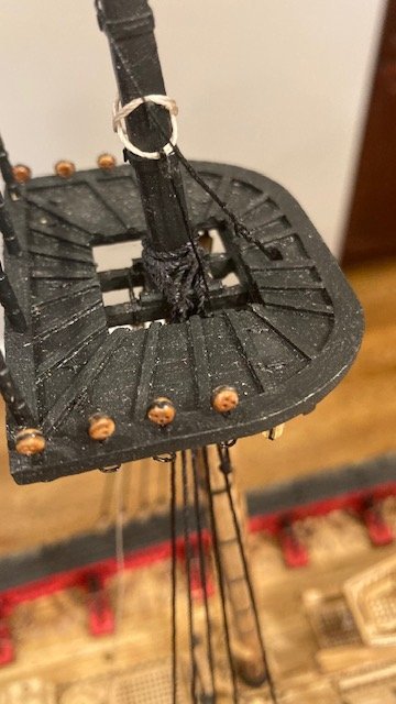
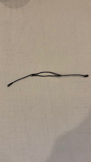
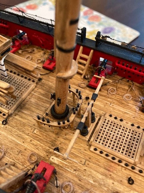
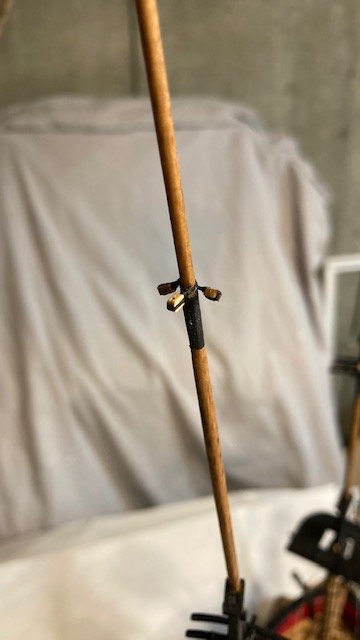
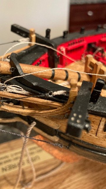
I completed the jeer blocks and slings before permanently setting the masts – it’s easier that way. The jeer slings were made from .012 tan line (doubled). To make the slings, I wrapped the line around the handle of my x-acto knife, tied the line with an overhand knot, applied a little CA, and trimmed the ends with nail clippers. The 1/8” single jeer blocks were seized to .012 black line. I looped the loose end of the line around the jeer sling and applied a little CA to create an eye and seized the line below the eye with some black sewing thread. The length of the jeer line from eye to tip of block is about 1 3/4”. The sling was made from .012 black line. I measured the length of the sling (about 5 ¾”) from the sling detail on Sheet 6. To err on the side of caution, I cut a 6” length of .012 black line. I made the oblong shaped stimulated thimble as shown on Sheet 6. The two loose ends have an eye. I made the eye on one end and then test fit the sling before looping the loose end through the completed eye. I found that had just enough line to loop the loose end through the eye and seize the line. So, for the next sling I cut a 6 1/2” length of .012 black line. Note: In the photo of the slings one sling is longer than the other. This is because the main lower yard is lower on the mast than the fore lower yard. Lastly, for the gaff throat halliard, I seized a generous length (17”) of .008 tan line to the 1/8” double block under the main top. Except for permanently stepping the masts, Chapter 17 is complete.
.jpg.dfe211a2f611a12e38a8550f80c594e4.jpg)
- 157 replies
-
- 4
-
-
- model shipways
- syren
- (and 1 more)
-
Glad you're back. Looking good.
-
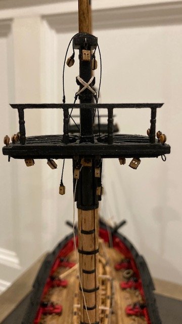
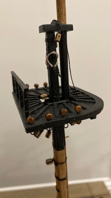
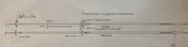
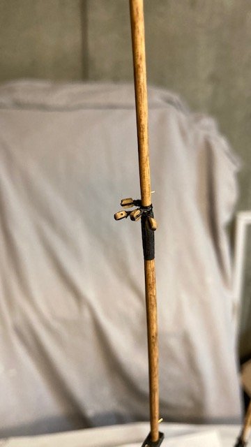
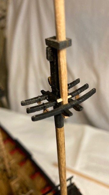
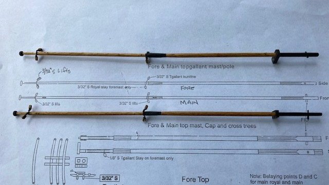
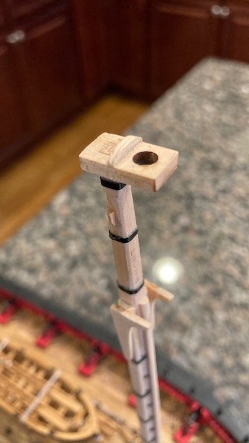
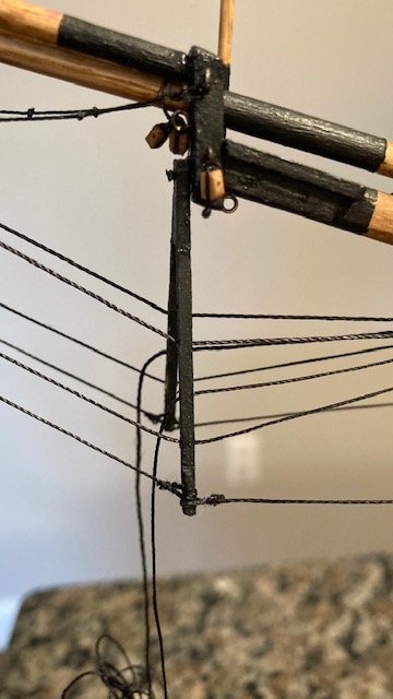
FYI, before starting the jeer block and slings, while I was reviewing WalrusGuy’s build log, I notice his topgallant masts have some additional blocks. So, I began reviewing the rigging plan on Sheet 7 and discovered that there are four (4) 3/32” blocks on the fore topgallant mast (2 for the lifts, 1 for the buntline, and 1 for the main royal stay). The plan of the fore and main topgallant mast/pole on Sheet 5 doesn’t show all of the block. I added two blocks to the fore topgallant mast. Likewise, I discovered there are three (3) 3/32” single bocks on the main topgallant mast (2 for the lifts and 1 for the topgallant bunt line). I added another block for the top gallant bunt line (See photos). Reviewing Sheet 7 was time well spent. I reviewed the instructions concurrently with Sheet 7 and made notations on Sheet 7 for later reference. I marked-up the plan view of the fore and main topgallant masts to show all of the blocks (see attached). Now it’s on to the jeer blocks and slings. Stay tuned.
- 157 replies
-
- 4
-
-
- model shipways
- syren
- (and 1 more)
-
Intriguing model. You definitely have a talent for model ship building.
- 99 replies
-
- 2
-
-
- winchelsea
- Syren Ship Model Company
- (and 1 more)
-
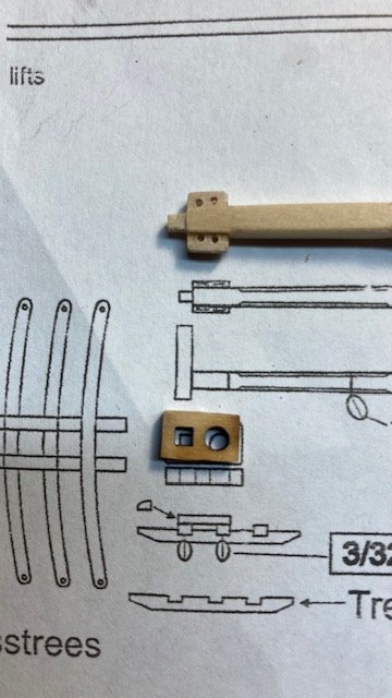
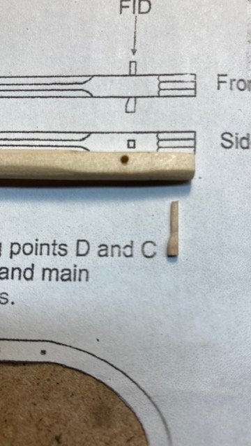
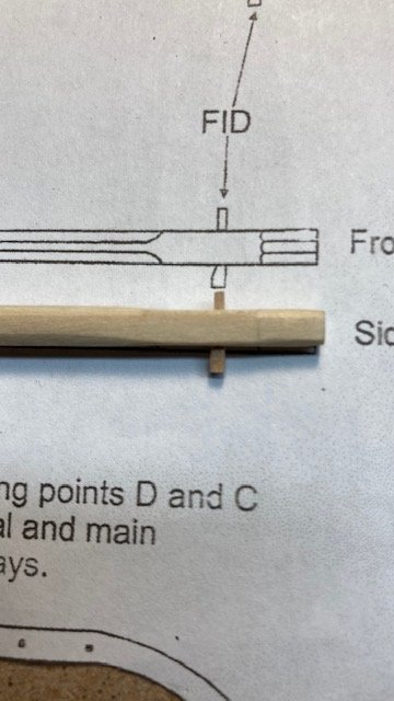
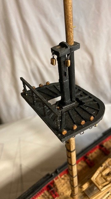
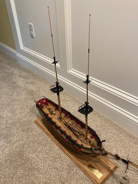
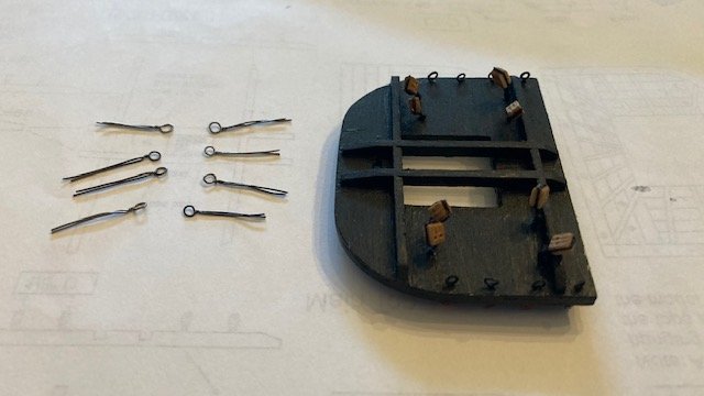
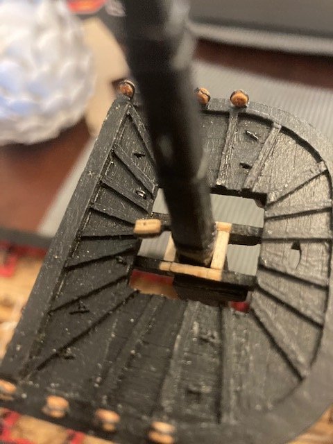
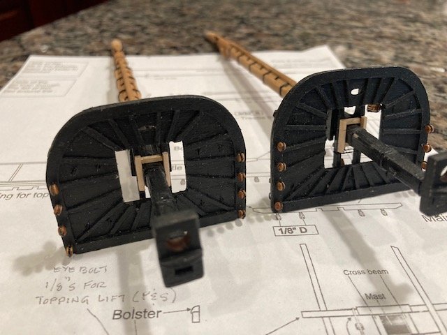
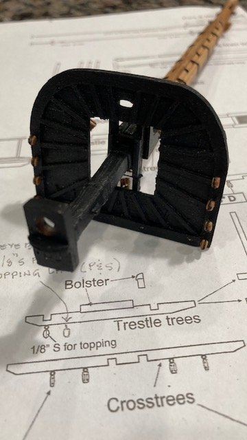
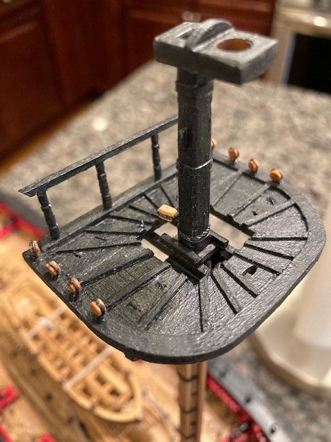
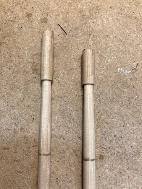
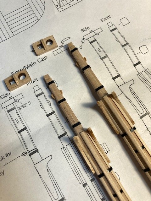
Completed the fore and top masts. The masts were made from 3/16” dowel and shaped to create the square and octagonal surfaces shown on the plans. Made the fids from a 1/16” x 1/16” strip and shaped them as shown on the plans. The cheeks were made from a 3/32” x 1/16” strip. Rather than file two small grooves on one side of each cheek to simulate the sheave holes, I glued the cheeks to the top mast and then drilled holes. I added a brass pin to each mast to secure the yards. I found the cross and trestle trees to be a bit tricky to assemble. I predrilled the holes in the ends of the cross trees before removing them from the laser cut sheet. In so doing, one of the cross trees split – good thing there is a spare. I followed the instructions in assembling and gluing the cross trees and trestle trees. Rigged the four 3/32” single blocks that hang from the top mast crosstrees and the one 1/8” single block on the fore top for the top gallant stay. The plans do not show where on the cross tress the 3/32” blocks are to be placed, only that two are located on the aft cross tree and two are located on the mid cross tree. However, the photo on Page 99, appears to show the blocks midway between the end of the cross tree and the trestle tree. So, that’s where I placed them. The bolsters were made from 1/16” x 1/16” strip as per the instruction. Painted the bottoms and tops of the top masts black and stained the rest Golden Oak. The fore and main topgallant masts/posts were made and shaped from 1/8” dowel. I used a makeshift lathe consisting of a Dremel and a cordless drill. I cut the dowel to a reasonable length, allowing enough length for insertion into the Dremel chuck and the drill chuck. I secured one end of the dowel to the Dremel chuck. The other end was allowed to spin freely in the drill chuck. This worked well. I used files and a sanding blocks to taper the dowel. The first top gallant mast was shaped without incident. The second topgallant mast snapped at the post. It was a clean break, and I was able to pin and glue the two pieces together – no harm, no foul. The fids were made and shaped using 1/32” x 1/32” strip. The simulated sheaves were created/drilled through the masts using a .55mm drill bit. I followed the instructions, i.e., marking the hole locations on both sides of the mast and then drilling the holes on both sides. Lastly, I added the ball truck on the tip of the mast pole, made from a scrap piece of 1/8” dowel sanded/filed down to scale and then drilled to accommodate attachment to the pole. The truck was painted black. The masts were painted black between the cap and the heal of the mast and around the top sheave. I added brass pins to secure the yards. The 3/32" single blocks for the lifts, bunt lines, and royal stay (foremast) were rigged to the finished topgallant masts. As a matter of clarification, Plan Sheet 5 does not show the 3/32” single blocks for the fore royal lifts. The plan is confusing in this regard. Refer Sheet 7 to see these blocks. I stepped the masts temporarily to check the fit and alignment. The main topgallant mast does have a noticeable rake aft. I had to file down the cross tree and the back side of the topgallant mast to get the proper rake. The fore topgallant mast had an excessive rake. Filing the cross tree and back side of the topgallant mast didn't correct the problem. The solution was to make a slightly longer cap, made from laser sheet stock. The longer cap is hardly noticeable. Next challenge, the jeer blocks and slings.
.jpg.9bcf05070fa6a9607e776e47d36e54c3.jpg)
.jpg.cfaa24ddac25ef1c41c9d784982339b2.jpg)
- 157 replies
-
- 4
-
-
- model shipways
- syren
- (and 1 more)
-
Fantastic work on rope coils. Photography is excellent, as usual.
- 950 replies
-
- 1
-
-
- syren
- model shipways
- (and 1 more)
-
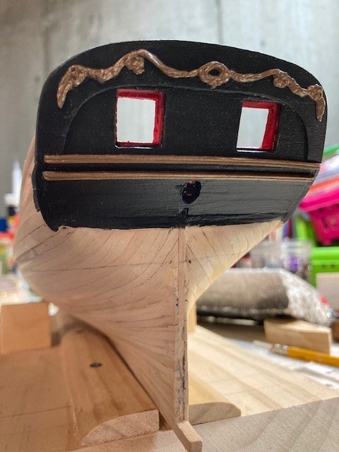
Transom looks good. The trim is a good addition. It de-emphasizes the black and draws your eye more to the carvings. Nice work.
- 436 replies
-
- 1
-
-
- Syren
- Model Shipways
- (and 1 more)
-
Like Dubz and rafine, I made my transom black - because I cracked the transom piece. You might want to remove the decorative carvings ( if you can) and paint the transom piece black. That would make the painted area around the door openings less obvious and emphasize the decorative carvings. I've attached a picture. Hope you don't mind.
- 436 replies
-
- 1
-
-
- Syren
- Model Shipways
- (and 1 more)
-
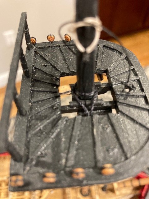
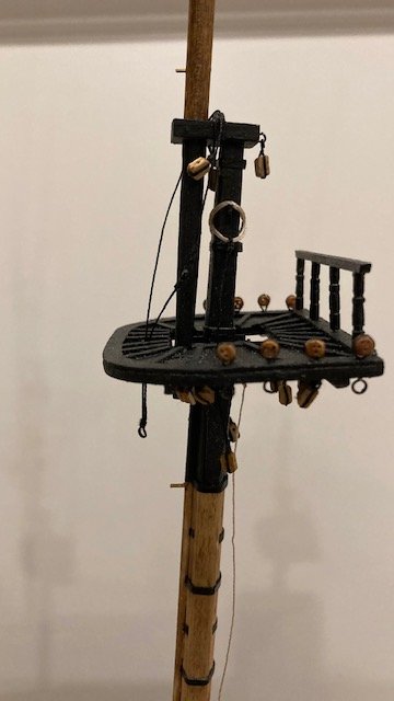
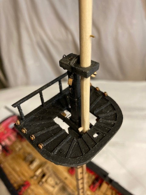
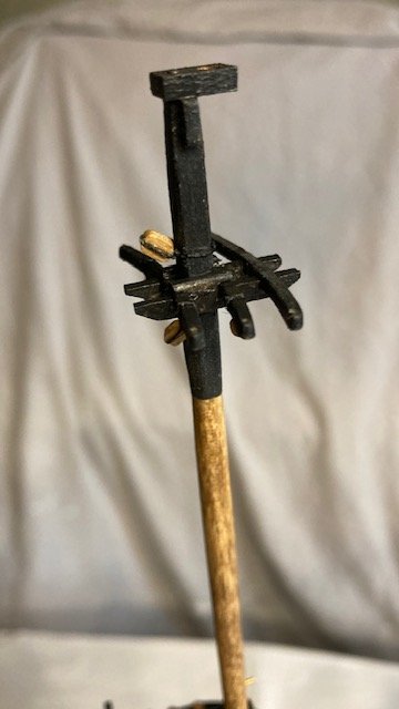
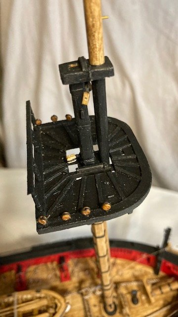
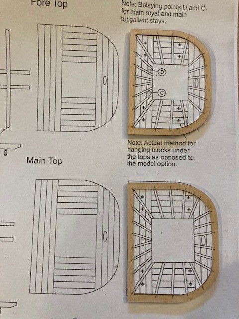
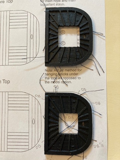
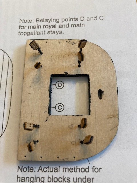
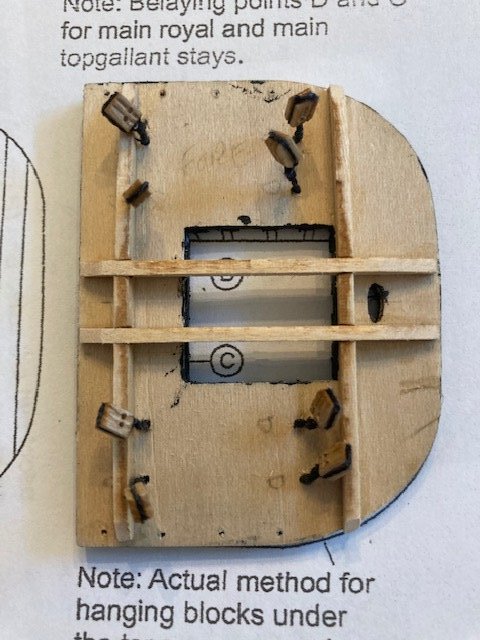
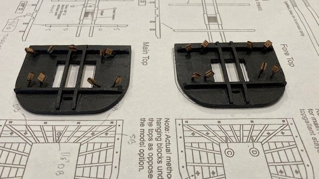
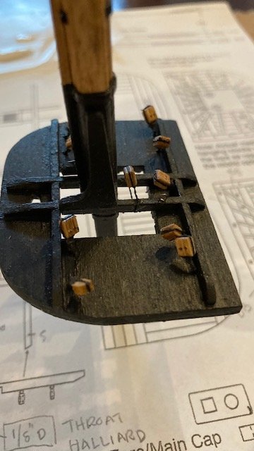
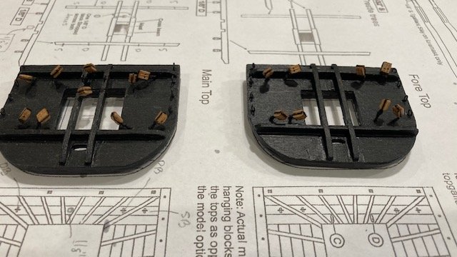
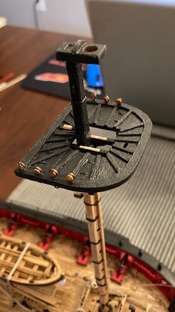
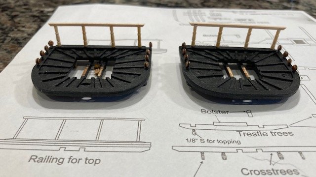
At this point, I’m one year into the build. The results have been good. Now, on to constructing the Main and Fore Tops. I cut out and dry fit the cross trees and trestle trees. Once I was satisfied that the cross trees and trestle trees “effectively” slide over the masts, I glued them together. I didn’t spend much time sanding the trees to remove the char because they are going to be painted black. The laser cut main and fore tops were next. I added the 1/8” x 1/32” planks as per the instructions. I sanded the edges of the top to even out the planks. I copied Walrusguy’s build and indented the edges of the plank joints so that once painted the planks are more visible. With that done, I cut out the laser cut rims, glued them to the planked tops, and sanded the outside edges of each rim flush with outside edges of the tops. The battens were next. To serve as a guide in positioning the battens, I cut out the plan view of the tops from Sheet 5 and placed it on the planked tops, marked the ends of each batten, and drew a pencil line between the tick marks. I marked the locations of the holes to be drilled for the blocks in each top and the two holes to be drilled in the fore top for the eye bolts for the lanyards for for the main top gallant stay and royal stay. [Note: The main top plan on Page 88 of the instructions shows nine (9) holes but Sheet 5 only shows eight (8). So, I’m not sure what the extra hole is for. Nonetheless, I rigged a 1/8” double block to it.] Each batten was cut from the 1/32” x 1/32” strip. The ends for the battens were sanded to the proper angle and glued on to the top. With the battens completed on both tops, I glued the base strip for the rails. I used a 1/8”x 1/32” strip for the base strip. I held off on gluing the trees to the underside of the tops until hanging the blocks – this gave me a little more room to work on the blocks. Somewhere along the way, I used all 8 yards of .012 black line. So, I used .008 black line to hang the blocks under the tops. [Note: I thought .018 black was too thick.] The instructions say to fold the line in half to create a loop that is pushed through the hole in the top. This is easier said than done. I had to make the holes larger in order to do this. Even at that, I still had difficulty pushing the loop through the hole. I threaded the line though a needle and pushed the head of the needle through the hole, pulled one loose end through the hole, and re-inserted the loose end through the hole. Next, I inserted the pin (cut from 28 gauge wire) through the loop and pulled the two loose ends down to tighten the loop. The pin was secured to the top with CA glue. I installed all of the loops before rigging the blocks. [Note: installing all of the loops would later be problematic when installing the blocks because the loose ends of the loops where in the way. I had to tape down the loose ends. Also, I wish that I had made the loose ends longer to facilitate tying the half knots.] Next, the blocks. There are four (4) 1/8” double blocks and the four 1/8” single blocks in the main top and eight (8) 1/8” double blocks in the fore main top. Installing the blocks was a tedious task. I tried following the instructions without success. I used a different method aided by 3/32” x 1/16” wood strip as follows: lay the wood strip across on the top (1/16” side down of course) between the loose ends, tie an overhand knot, apply a little CA glue to the knot to secure it, slide, but not remove, the wood strip to release it from the rigging line, apply a little CA to the block and place the block on the rigging line to hold it in place while you tie the block with the loose ends using an overhand knot, secure the knot with CA, snip off the excess rigging line with a nail clipper, remove the wood strip while holding the block with tweezers, seize the two rigging lines together below the block. Note: This process won’t work if the cross trees and trestle trees are glued on. It worked well for me, and it gave each block a uniform height below the top. I became more proficient at it with each successive block. I completed the fore top blocks first, then, I glued the cross trees and trestle trees in-place. Here are some photos. I completed the main top blocks in the same manner. However, I did make a mistake. The first two blocks that I installed were the aft, outboard, port and starboard blocks. I wasn’t paying attention to the plans and installed double blocks instead of single blocks. I decided to leave them as is. I painted the underside of the tops black – only one coat because the bottoms will not be seen. Added the eye bolts for the lanyards for the main top gallant stay and royal stay and the blocks for the boom topping lifts in the main top trestle trees. I made the eye bolts from 28 gauge wire - Somehow, I used all or lost some of the 320 small (1/32") brass eye bolts furnished with the kit. Next, I stropped the 1/8” double block for the throat halliard. I didn’t spend a lot of time on this – just tied a simple knot and applied CA to secure it to the trestle trees. Any more detail than that won’t be noticeable. I made the deadeye plates from 28 gauge wire. I wrapped the wire around a round nose pliers. The most difficult part is setting the 2.5 mm deadeyes so that the two holes are across the top while wrapping the wire around the deadeye. Once I had the deadeye in-place and lightly wrapped, I applied some CA to secure it. Note: I found that if you apply too much pressure the deadeye will break. I finished off the plate by snipping the wire with nail clippers and filing the ends to flatten them. The tops of the deadeyes will be obscured when the top mast shrouds are rigged. The top rails were made using 1/16” x 1/16” strips per the instructions. The stanchions were made using the same wooden decorative toothpicks that I used for the fife rail legs. I drilled .55mm holes in the end of each stanchions and glued a short length of 28 gauge wire into each hole to secure the rail stanchions to the base strip along the top. I used white glue to attach the stanchions to the rail. When the glued was sufficiently dried, I applied CA to the rail/stanchion joint to secure the stanchion. I laid the completed rail and stanchions down on the top to align the stanchion pins with the base strip and then drilled a hole in the base strip at the location of each pin. I attached the rail and stanchions to the base strip temporarily and painted them black. Next up, the (1/16” x 1/16”) bolsters and cross beams. I marked the location of the cross beams on the trestle trees. I glued the aft cross beam between the trestle trees on both the fore and main top. This helped in positioning the top on the mast assembly. Whence the top was secure with CA, I added the fore cross beam to each top. The bolsters were next. These were easy. Painted the cross beams and bolster black. Time to move on to constructing the top masts. Stay tuned for progress.
.jpg.ed156a14e815cebd1279ed0d39775e38.jpg)
.jpg.8cdb5bf2293688ce051f06b081f6cc7c.jpg)
.jpg.3144fb2b18c8f84aa6e3a5eede6cbd20.jpg)
.jpg.12f3ca75182cfe03cfd925485e6384bd.jpg)
.jpg.1c102378836de8d703caf7d5e95ca700.jpg)
.jpg.18cb58f59c0e6c07203c11b725b594b7.jpg)
.jpg.e469a9f6aafb0679ab8ca68300e84fc6.jpg)
.jpg.fa4ed201713be1ed271c011f25689a4d.jpg)
.jpg.e4a4de0e167d30347718bee723dc8343.jpg)
.jpg.75465614af818227d8a3ee94c001cceb.jpg)
- 157 replies
-
- 6
-
-
- model shipways
- syren
- (and 1 more)
-
Excellent work and perseverance on the stern carvings.
-
Nice work on the boom irons. Did you drill them with the push pin drill and did you score the tube. BTW, your photography is superb. This is not germane, but are you an Oilers fan?
- 950 replies
-
- 1
-
-
- syren
- model shipways
- (and 1 more)
-
Hope all goes well and that you have a speedy recovery.
-
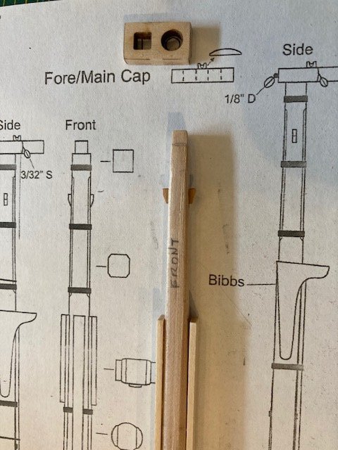
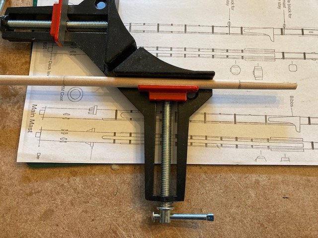
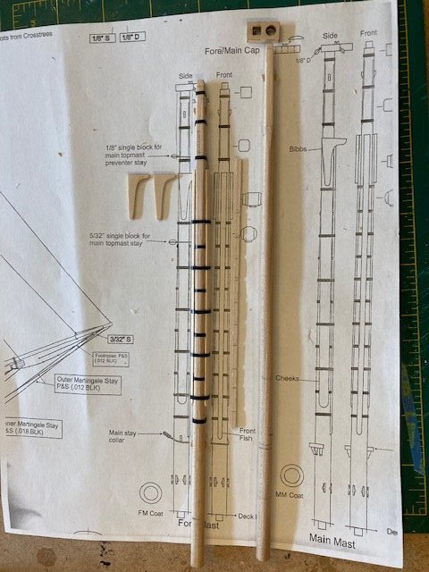
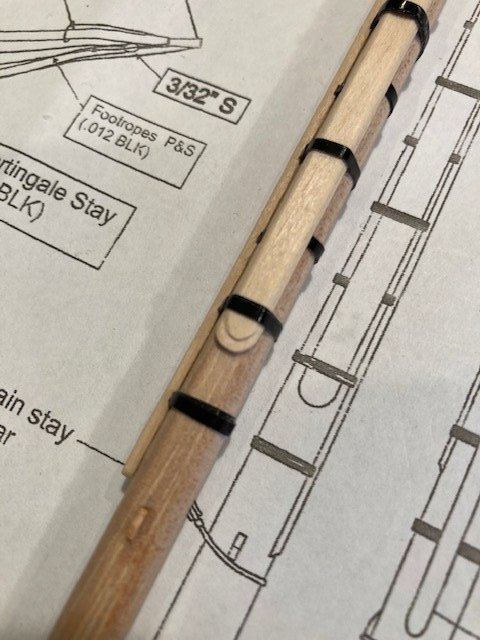
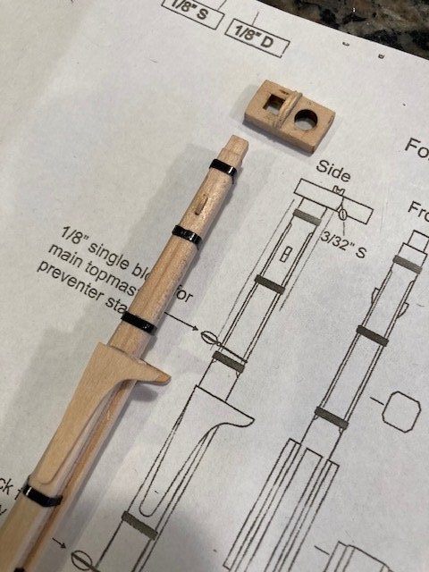
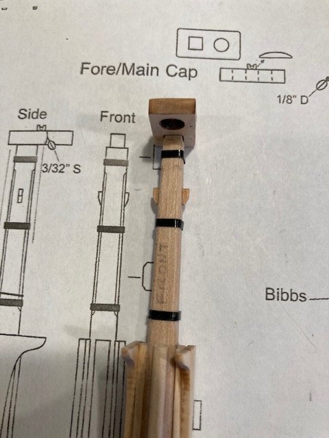
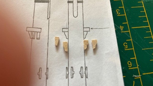
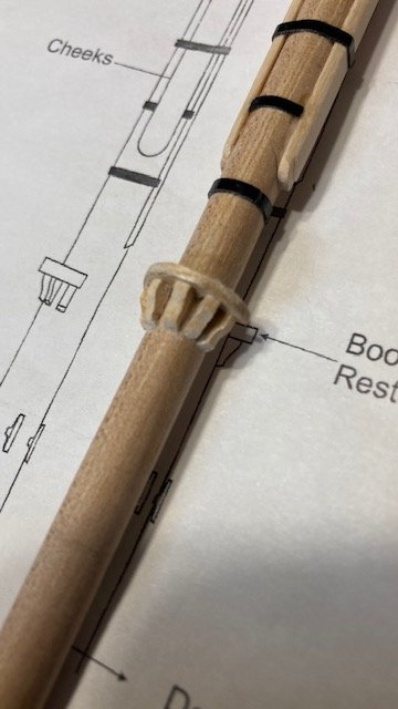
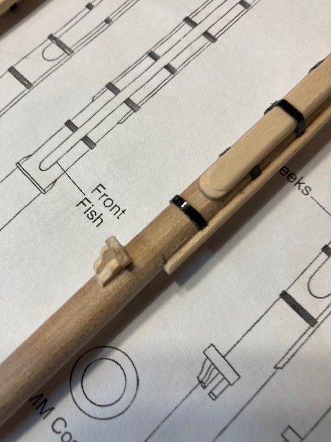
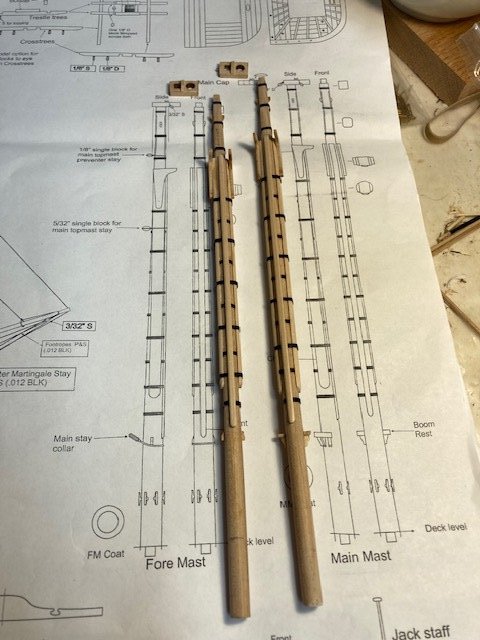
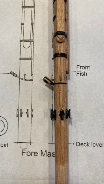
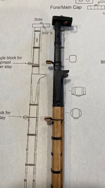
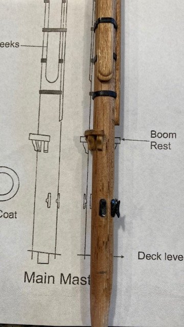
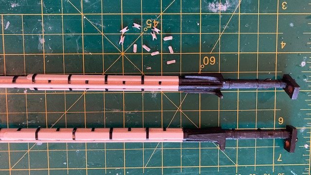
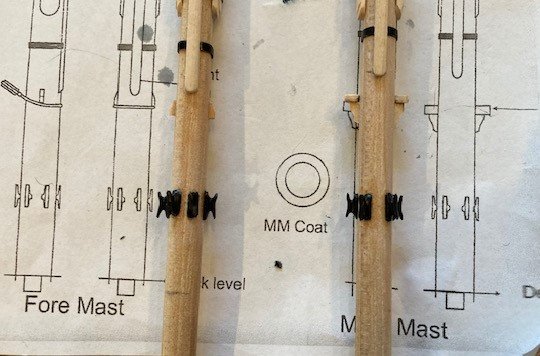
On to Chapter 17. I had previously drilled the holes for and rough cut the 5/32” dowels for the fore and main masts back in Chapter 7. I had drilled the holes 1” deep. Before cutting the dowels down to size, I inserted each dowel into the predrilled hole and marked the top of the deck on each dowel. I scaled the length of the masts on Sheet 5 from the top of the deck to the top of the mast cap (Fore Mast: 8 13/16”, Main Mast: 9 9/16”). I cut the dowels longer to allow from inserting the dowel into my drill chuck for tapering the masts to about 3/16” at the top, as measured on Sheet 5. After tapering, the dowels were cut to final length. Starting with the fore mast, I filed and sanded the top of the mast to a square profile. I drew four pencil lines to demarcate the four square sides. This is very helpful when you rotate the dowel to file the next side. To keep the dowel from twisting while filing and sanding, I used a right angle picture frame jig. Once the sides were square, I made the tenon at the top of the mast and chamfered the corner edges of the squared portion of the mast. I flattened the port and starboard surfaces of the mast to receive the cheeks, and slightly flattened the front of the mast to receive the front fish. The cheeks were made from a 3/16” x 1/16” strip, glued, shaped, and the “fingernail” made as per the instructions. Next, the simulated iron bands were added using 1/16” pinstripe tape (not furnished with the kit) per the instructions, except for the bands that run under the cheeks. Rather than wrap these bands around the entire mast, I opted to cut strips to fit between the cheeks. I only used two (2) strips. I applied CA glue to the cut ends of all of the bands to preclude them from lifting up. The front fish was next. For risk of damaging the bands when sanding down the front fish, I took a page out of SalD’s log and decided to round off the front fish before gluing it to the mast. I attached the front fish to a scrap piece if ¼” dowel with double sided tape and then sanded the front fish to shape. The front fish was then aligned with the bands on the mast and the band locations were marked with a pencil on the backside of the front fish. I scribed a line on the pencil marks and on the edge of the front fish and then created a notch to fit over the bands. I added the two chocks/cleats at the top of the mast head and the two (2) below front fish. I shaped them first, glued them, and then did some final shaping with a file. Lastly, I added the laser cut bibbs, making sure that the tops of the bibbs are parallel with the water line. Note: The bibbs are fragile and can easily break along the grain. The main mast was completed in same fashion as the foremast. The boom rest was made from 1/16” basswood sheet. I used a 9/16” circle template to mark the outer radius and a 5/16” template to mark the inner radius. The boom rest was cut out with an x-acto knife. The corbels (knees) under the rest were made from 1/16” x 1/32” strip. I pre-shaped them before gluing them in-place. The tops of the corbels need to be angled to match the angle of the rest. I glued the center corbel first, the two end corbels next, and then did a final shaping on them. The other two corbels were then glued in-place and final shaped. I decided to add the saddle for the lower yard sling on top of the cap. In so doing, I left space between the saddle and the top mast for the lower lift blocks. I made the saddles from a sheet of 1/16” basswood. I used a 5/8” diameter circle template to establish the curvature of the saddle. The notch in the top of the saddle was made by running an x-acto knife across the saddle and then filing along the cut with a half-round file. The notch needs to wide enough for the .012 black sling. I also added the eye bolt to the main mast cap for the 1/8” double block for the gaff peak halliard. The tops of the masts were painted black down to the iron band below the bibbs. Next, the 5 mm metal lower cleats were filed and spray painted black. I stuck the cleats to a piece of masking tape to hold them secure while spray painting them. I attached the four (4) cleats to the main mast and the six (6) cleats to the fore mast with CA glue. I then stained the masts with Minwax Golden Oak. To complete the fore mast, I rigged the 1/8 single block for the main topmast preventer stay, 5/32" single block for the main topmast stay, and the main stay collar (5mm closed heart). As others have found, 5/32” blocks are not included in the kit. Fortunately, I had some from my Fair American build. The following is a link I used for rigging the blocks to the mast: https://youtube/WUrRb66VSSE. This is a good technique. I used .018 black line and black thread for the whipping. With that, I’m moving on to constructing the fore and main tops. Stay tuned.

- 157 replies
-
- 3
-
-
- model shipways
- syren
- (and 1 more)
-
I like the bands on the spars - a nice addition. I think I'll copy you when I reach that stage. Looking good. You better slow down or you'll be starting your next build soon. haha.
- 950 replies
-
- 1
-
-
- syren
- model shipways
- (and 1 more)
-
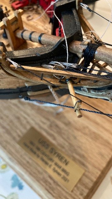
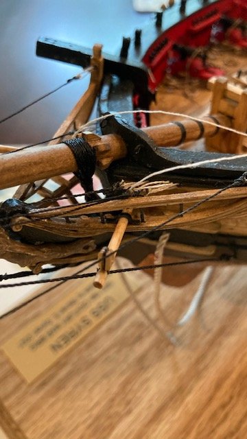
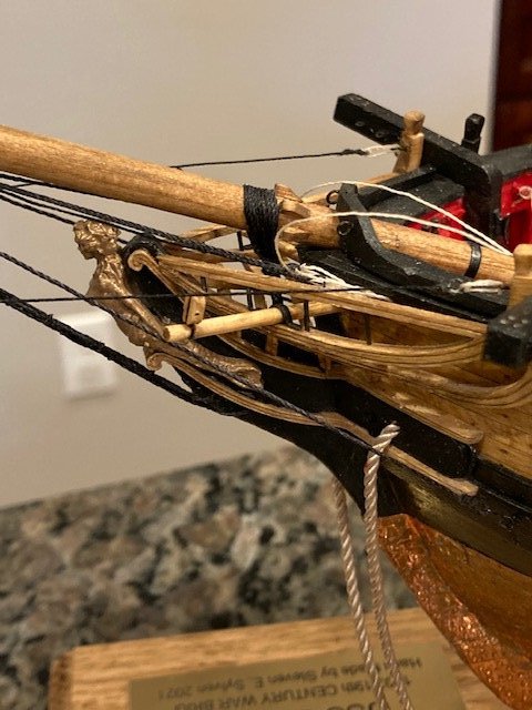
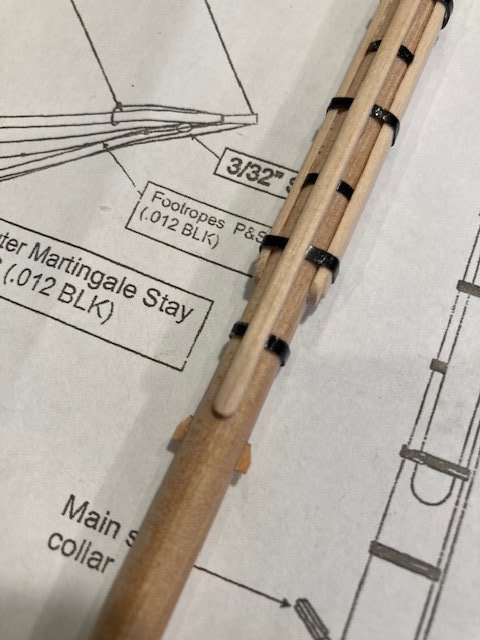
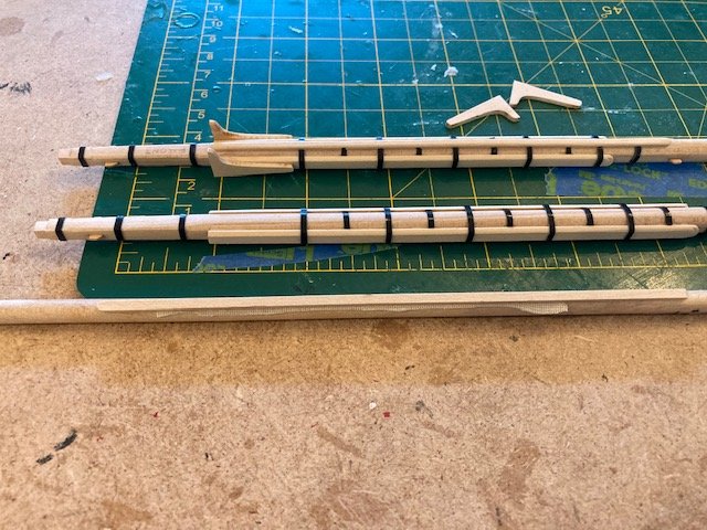
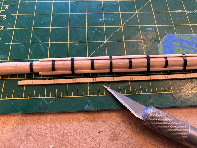
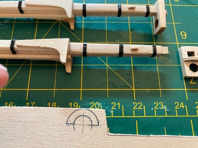
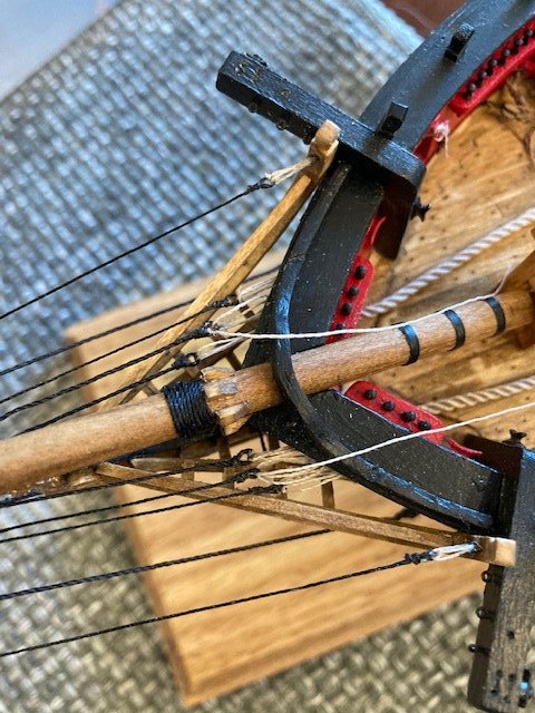
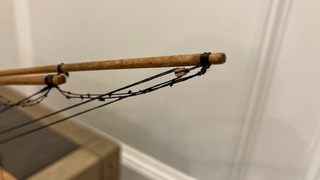
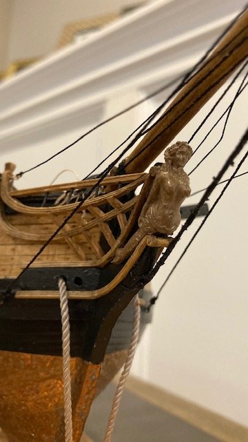
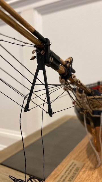
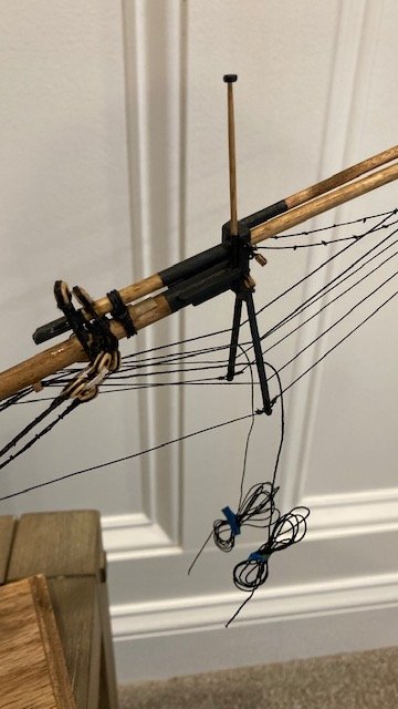
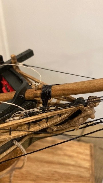
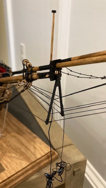
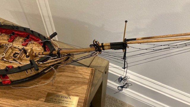
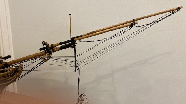
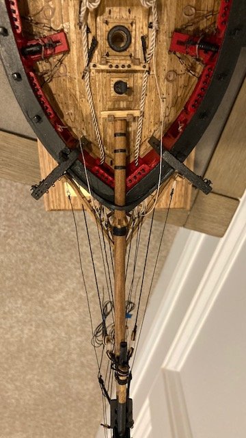
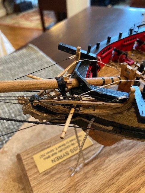
This being April Fool's Day, it's no joke that I made progress on the the ship. But, as a matter of note, one thing that I’ve learned in model ship building is that Murphy’s Law - "Anything that can go wrong, will go wrong" - is ever present. With that aside, I’m continuing with Chapter 16. I glued the bowsprit in-place and allowed it to dry sufficiently before gammoning. I set up the gammoning with .021 black line, made the eye, thread the loose end through the eye and then rove it through the gammon hole. I found this to be somewhat difficult, mostly because the head rails block your view. I was able to make the 9 turns and 9 half-hitches as per the illustrations in the instructions. I used CA to secure the line while I was wrapping it. I lashed the bobstays and the bowsprit shrouds to their corresponding hearts with .008 tan line. The space between hearts (1/4”) is consistent with the scale of Sheet 5, however, I had to re-do one bowsprit shroud because the spacing between hearts was too close. I used CA to secure the lashing. I assembled the jibboom and the flying jibboom and lashed the jibboom to the bowsprit with three (3) turns of .028 black line. In the process of assembling the flying jibboom, I didn’t realize that the traveler ring slipped off until the flying jibboom was glued in place. Fortunately, I used white glue, so I was able to disassemble the flying jibboom, replace the traveler ring, and reassemble the jibboom. Just a word of caution: Make sure the bend at the top of the ring can pass the line size before permanently assembling the bow sprit. With that done, I moved on to the stays. I decided to set up the outer martingale back ropes (.012 black) first. I made a "bullseye" in one end and then measured the length of the stay from Sheet 5. I seized each stay to the bottom of the dolphin striker with the striker off the bowsprit. After permanently attaching the striker, I temporarily set up each stay with a lanyard (.008 tan) attached to the upper headrail eye. So far so good. Next, the inner martingale stays (.018 black). I set up the lanyards temporarily, lashing them to the eye bolt closet to the bowsprit. This is the reverse order of what’s described in the instructions. I made only two passes – that’s all that can fit through the 1/32” eyebolts. Setting up the lanyards was easier than I expected. The key is to have a stiffened loose end to feed through eye bolt. I seized each stay to the tip of the jibboom. Then, I tightened each lanyard and secured it with CA glue. The outer martingale stays (.012 black) were next. I set them up a la the inner martingale stays. They were fairly easy because they pass through 3/32” blocks on the end of the flying jibboom and are seized to the bottom of the dolphin striker. Lastly, I tightened the lanyard and secured it with CA glue. I temporarily set up the lanyards for the fore royal stay (.012 black) and the fore top gallant stay (.018 black). While setting up the fore royal stay, the eye bolt came out from the bow - UGH!. It was nearly impossible to get the eyebolt back in, but I persevered - These will be permanently set up in Chapter 18. Lesson learned: Make sure the eye bolts are secure before setting up the stays. To complete Chapter 16, I made the foot ropes – they are definitely troublesome. I soaked a length of .012 black line in water, applied a clip to each end and hung it to dry. I didn’t find much discussion in other build logs on making the footropes, but this is the method I used: (1) loop the line over the end of the jibboom, (2) tie the two loose ends with an overhand knot, (3) slip the knot up to the jibboom, (4) apply CA glue to secure the knot and trim the loose ends, (5) cut each footrope loose end long enough to provide the desired drape and to seize it to the eyebolt on the bowsprit cap, (6), make nine knots (.008 black) on each footrope, spaced at approximately 3/8”, (7) apply CA to each knot and trim the ends – do this one footrope at a time so you can align the knots on each rope, (8) pass the loose end of each rope through the bowsprit eye bolt, (9) adjust the rope to the desired drape and then apply a little CA to the eye bolt to secure the line, and (10) seize the line with black thread. For the footropes between the end of the jibboom and the end of the flying jibboom the process is basically the same except for seizing the end of the ropes at the end of flying jibboom and making six (6) knots in each rope. I applied one coat of 50/50 mixture of white glue and water to the footropes. Murphy’s Law notwithstanding, I’m happy with the results of Chapter 16. More photos follow. The wound up ropes in the photos are the fore royal stay and fore top gallant stay. The bumpkins are temporarily placed – I created these back in Chapter 10. I think I’ll hold off on permanently installing them until I rig the fore mast and top gallant stays. A single block needs to be seized to the end of each bumpkin for the fore course tack. It’s best to do this with the bumpkin off ship.
.jpg.1bf90700d5122b86ed44d6ab4ce949fb.jpg)
- 157 replies
-
- 5
-
-
- model shipways
- syren
- (and 1 more)
-
Excellent work on the carronade mounts - very innovative.