

abelson
-
Posts
467 -
Joined
-
Last visited
Content Type
Profiles
Forums
Gallery
Events
Everything posted by abelson
-
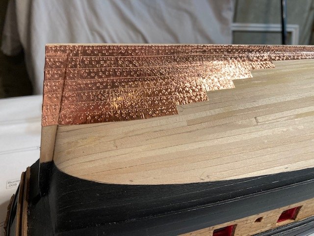
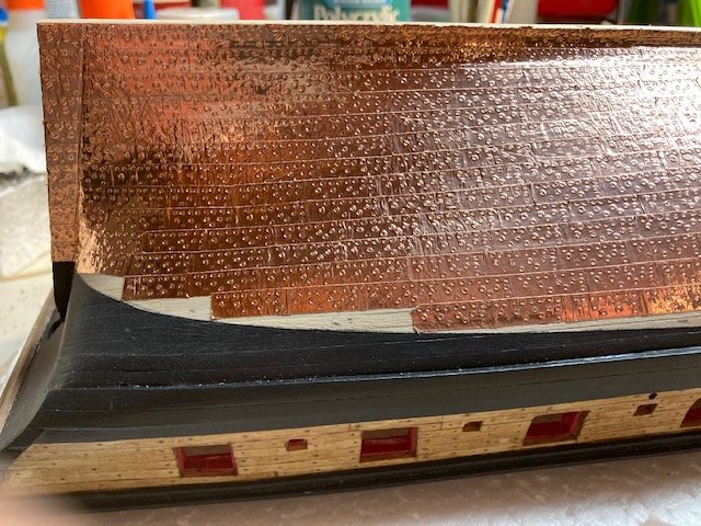
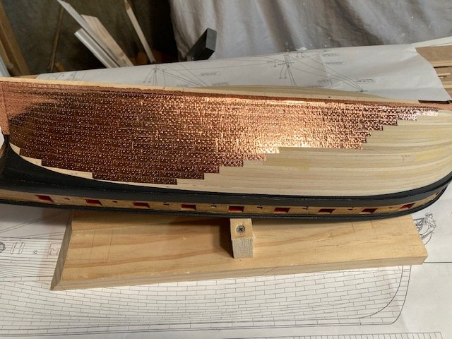
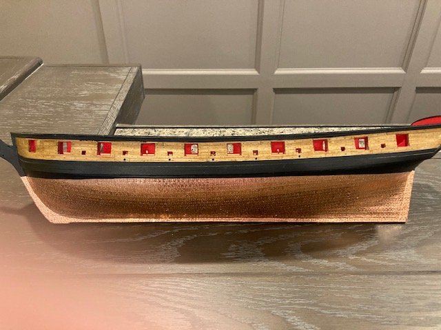
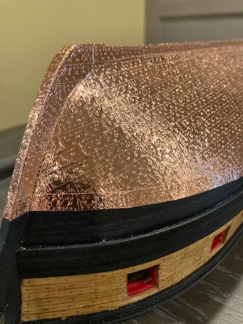
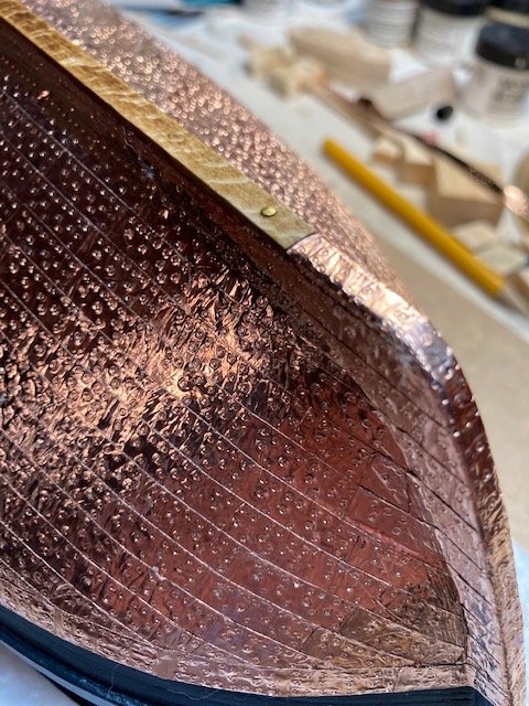
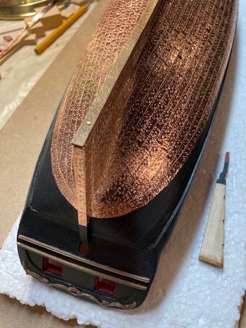
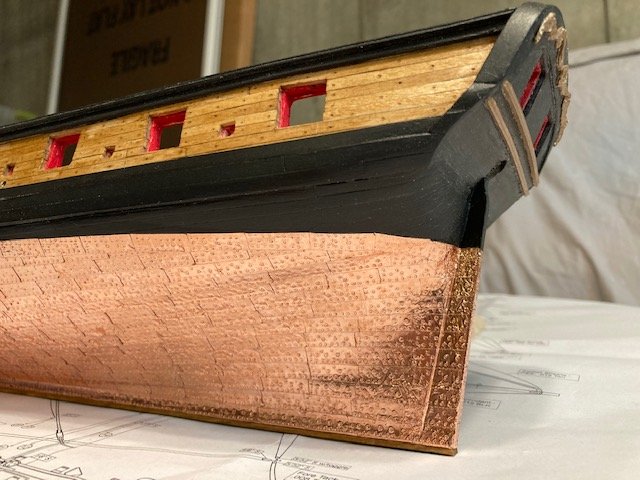
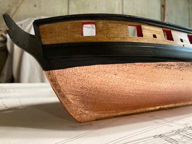
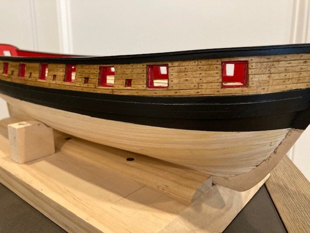
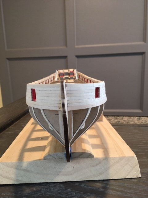
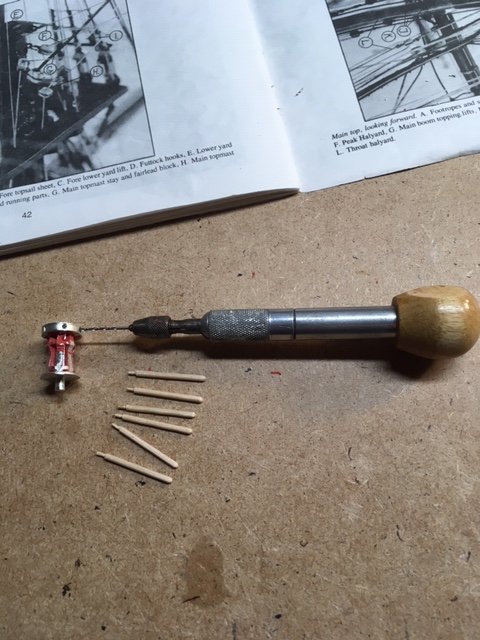
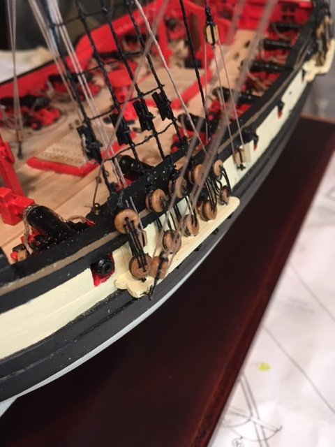
 Moving on to Chapter 8, I cut 17” strips of copper tape (22 plates per strip) and stamped out nearly 200 port side copper plates. The stamp sheared off several times – probably struck it too hard with the hammer. I was able to repair it with CA glue. To break the monotony of cutting plates, I cut the plates on several strips at a time, applied them to the hull, and repeated the process. The most difficult part for me was separating the backing from the plate. I used a pair of bent tweezers to help position the plates on the hull. Positioning the plates is all hand/eye coordination. My jewelers magnifying glasses came in handy here. I studied the standing rigging plan (Sheet 7) to see how the plates lined up at the bow. Beginning at the keel, the first three rows of plates line up with knee plates. Thereafter, the rows of plates work their way upward towards the waterline and they don't align with the knee plates. I completed the port side plates except for the dressing belt along the waterline. Like some other build logs, I made a stamp for the dressing belt plates (the "missing plate"). The port side stamping left an impression in the jig baseboard. So, before starting to stamp the starboard side plates, I moved the jig. This would have been easier to do had I screwed the jig to the baseboard. Completed the copper plating. It’s not perfect, but I’m satisfied with result considering that it’s my first copper plating experience. As some other build logs have done, I decided to copper between the keel and false keel, but primarily because I didn’t like the look of the first row of plates along the keel. I used the dressing belt stamp for these plates. I wiped the copper plates with acetone (nail polish remover) to remove fingerprints. I stained the false keel with Minwax Golden Oak, glued it and attached it with brass pins. I applied a mixture of vinegar and salt to the copper to remove the patina. Next up, the rudder.
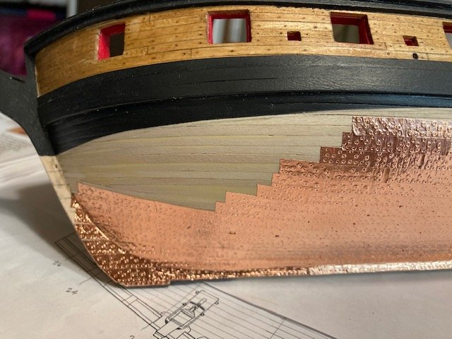


- 157 replies
-
- 6
-

-
- model shipways
- syren
- (and 1 more)
-
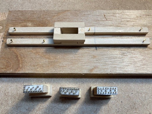
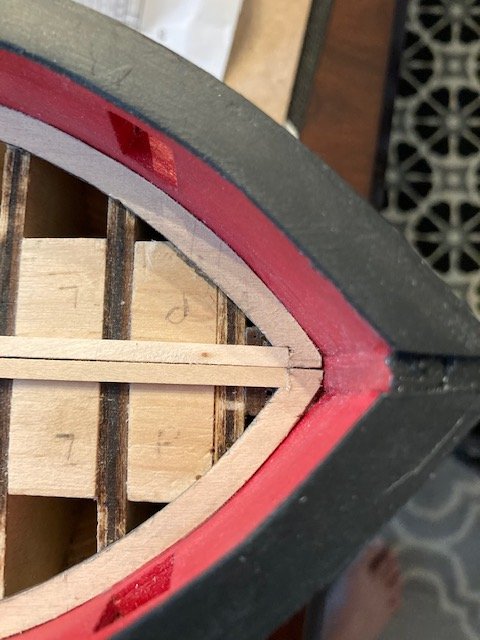
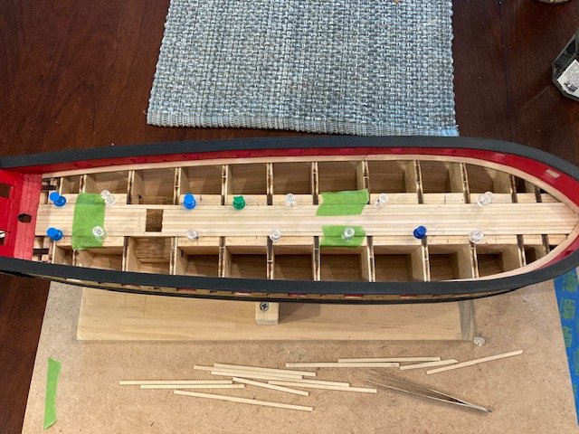
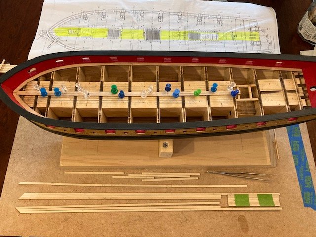
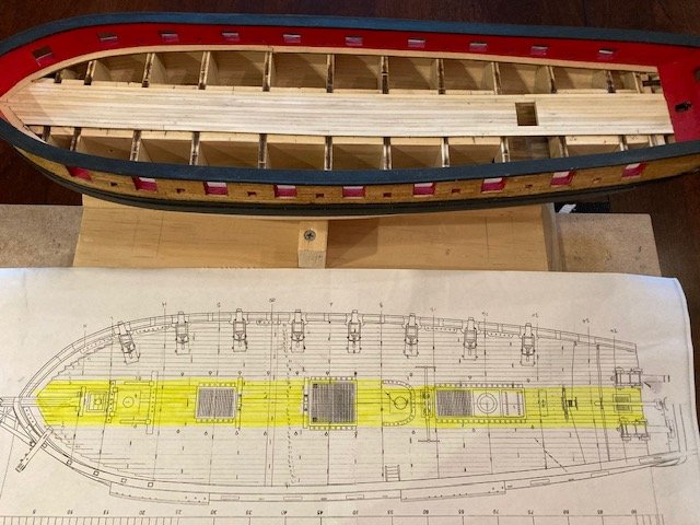
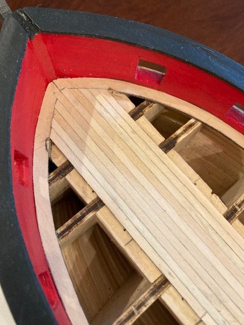
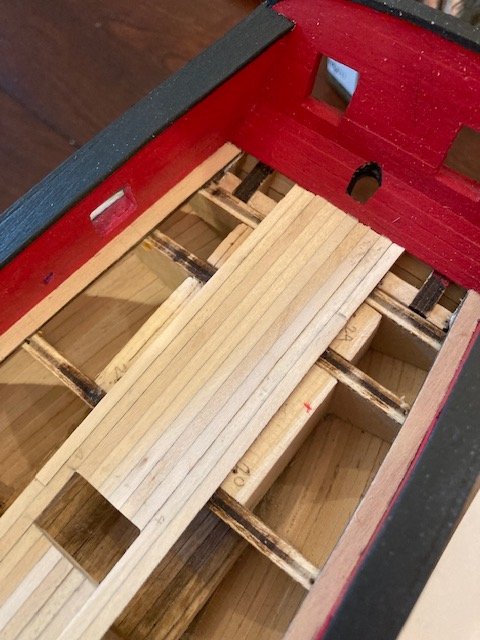
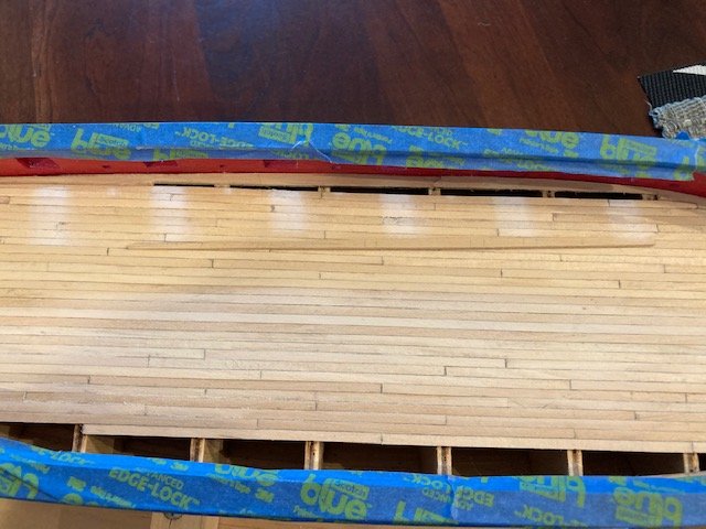
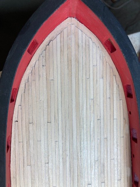
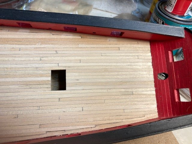
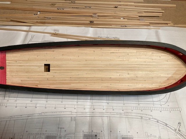
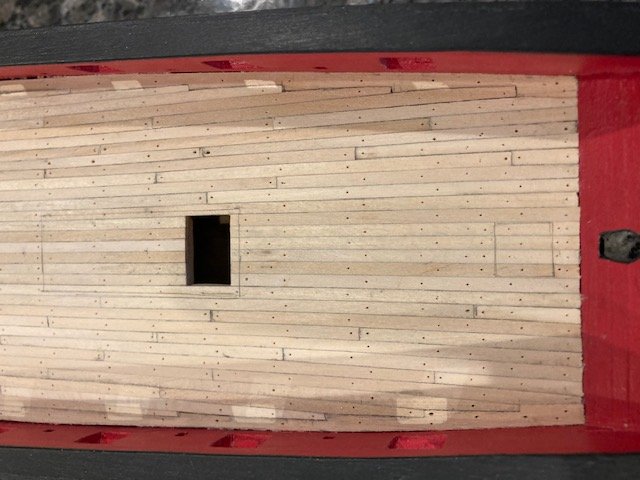
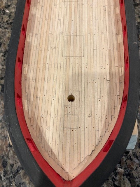
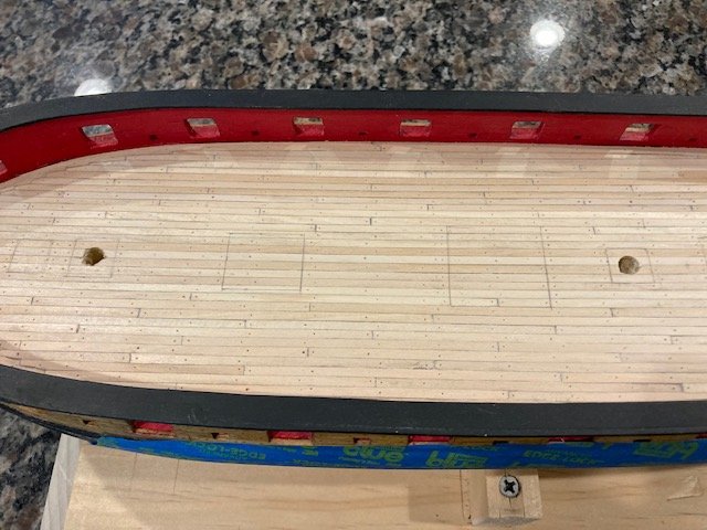
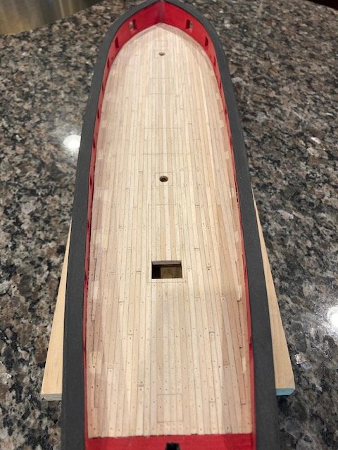
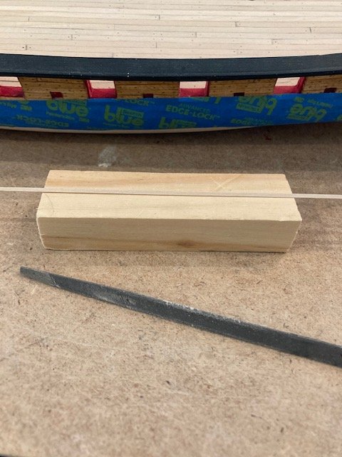
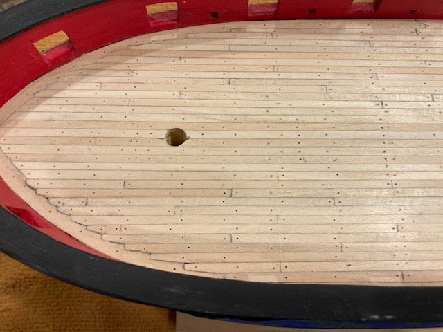
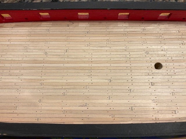
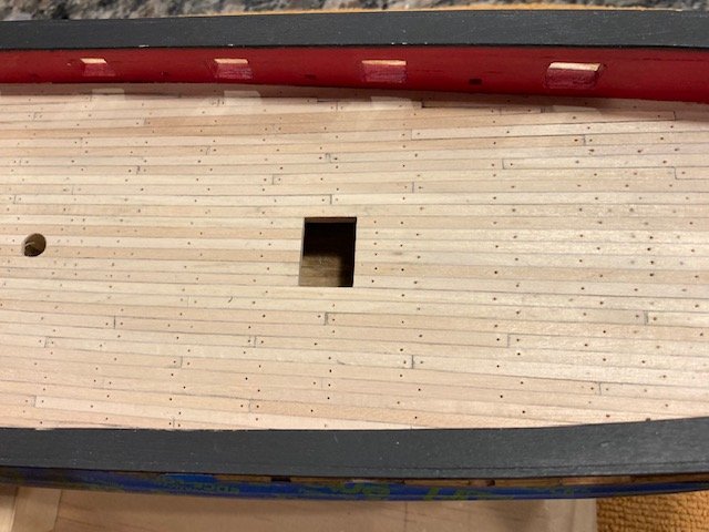
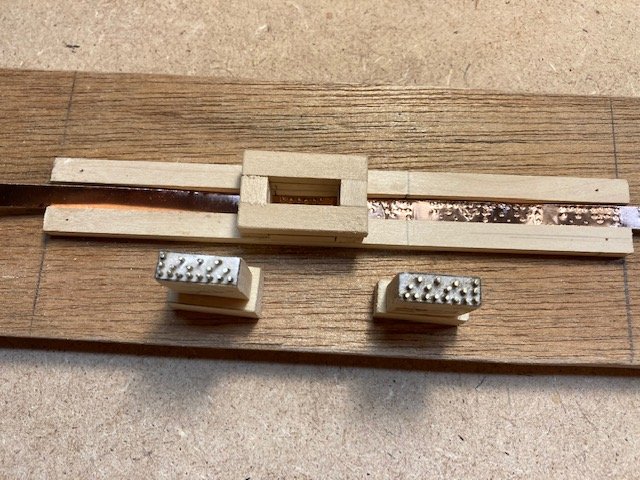
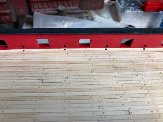
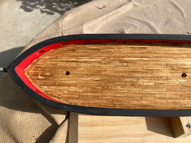
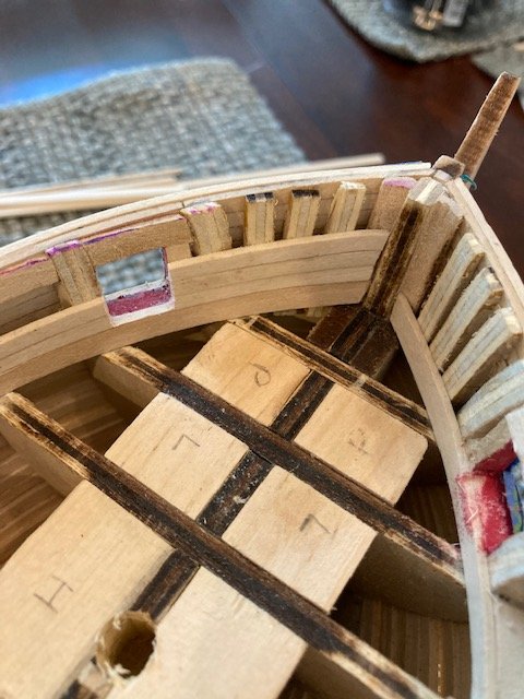
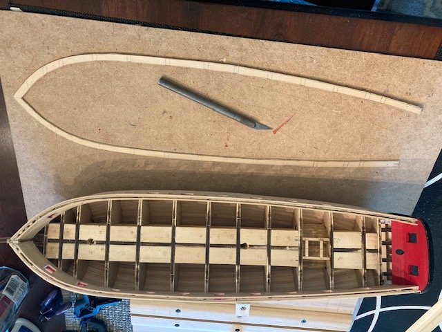
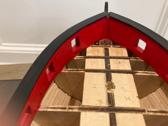
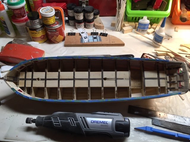
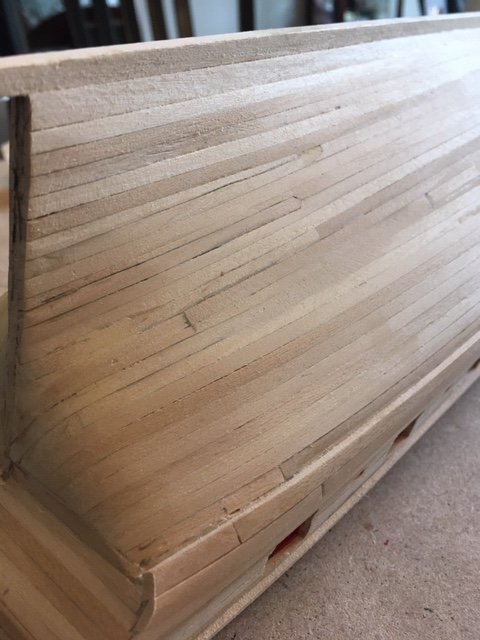
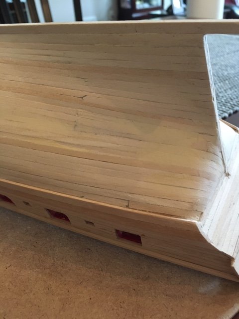
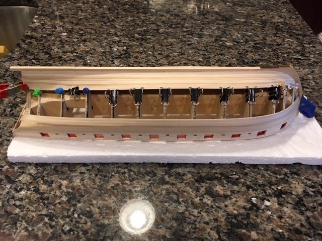
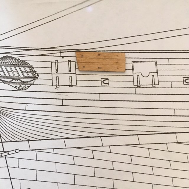
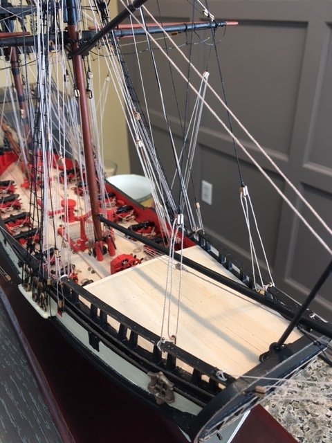
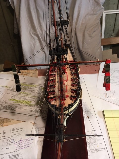
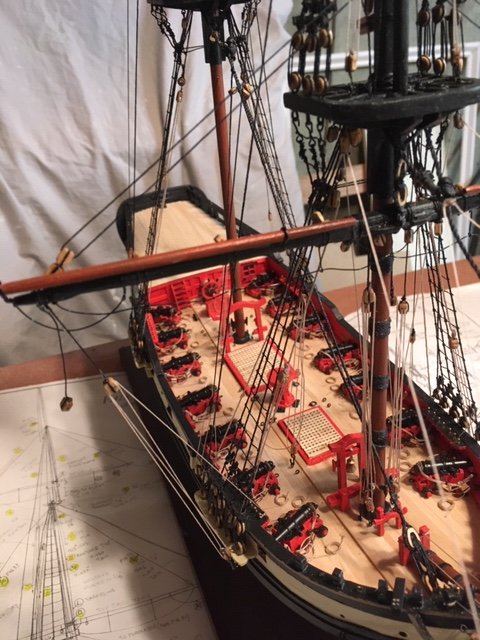
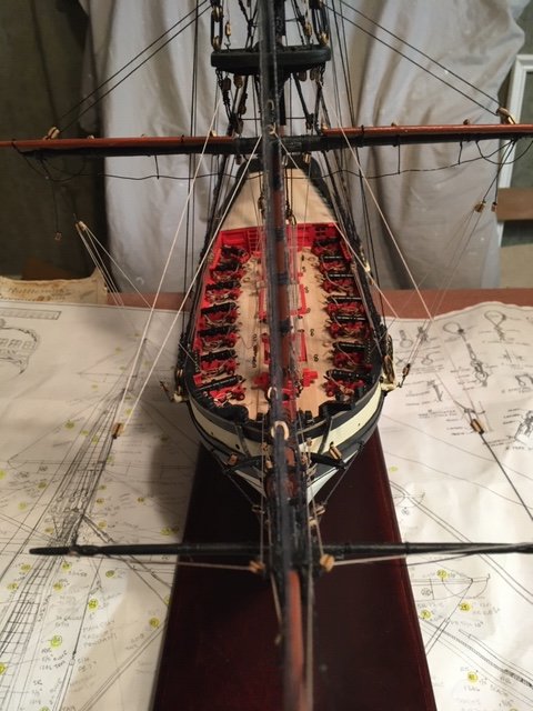
The laser cut margin planks did not fit well, so I decided to make them from the basswood sheet left over from the cap rails. I tried making the margin planks in one piece. I used a paper template to get the shape of the bulwarks and then traced it onto the wood sheet. After cutting the margin planks out with an x-acto knife, I test fit them. I didn’t like the way they fit at the bow. So, I made some tweaks to the template and re-cut the margin planks – this time from the bow to one bulkhead beyond bulkhead D. I placed the scarph joint at bulkhead D. After much sanding and refitting, the port side margin plank fit well. I cut the original port side one-piece margin plank to fit between the scraph joint the stern planking. I glued both margin planks and secured them with push pins. I repeated the process for the starboard side. Something that I’ve noticed in the instructions is that the margin plank has only one scraph joint. Like other build logs, I followed instructions and fashioned the margin plank with one scraph. Most likely, the margin plank was built with more than one joint - just saying. I spent a considerable amount of time studying build logs and reading Planking the Built-up Ship Model – the plank layout is confusing. Assuming a full-length plank of 20’+, I decided to use the “four step butt” arrangement. This meant the space between bulkheads was counted as a deck beam. Basically, with the four step butt, there is a joint in the same plank at every 5th beam, and the separation between joints on the same beam is 4 planks, i.e., there is a joint every 5th plank. I developed a joint pattern using the deck plan on plan sheet one. I used full width planks from bow to stern instead of tapering as other builders have done. Like some other builds, I laid in the first 4 planks on either side of the center line with no butts. I marked one edge of each plank with a #2 pencil to simulate the caulking between planks. Note: I forgot to pencil the first margin plank, so, when you start planking, remember to mark the planks before laying them - it's much easier. These planks were set flush with the margin plank. The remaining planks were “nibbed” or “joggled” at the margin plank. I rather crudely put some masking tape on the cap rail and sheer strake to protect it. I measured and cut the first 4 planks and test fit them on the deck and inserted push pins on the outside edge of the last plank and taped them. I also numbered the planks in case I had to realign them. The last plank on each side aligns with the edge of the companionway. I left the planks in-place while I removed, glued, and reinserted the 2 center planks (see photo). This way, I was sure that the first 2 planks would be aligned perfectly along the center of the deck. Before the glue dried, I removed the other planks, one side at a time, and pinned the edges of the two glued planks. Thereafter, I glued the rest of the planks, one at a time. The 5th plank is the first plank with butts. I laid down the plank, marked the butt locations using my pattern, and then cut and glued the planks. The 6th plank is the first joggled plank. I cut the joggle, traced the shape onto the margin plank, notched out the shape with an x-acto knife, and filed the notch to get a relatively clean edge. I used the first joggled plank as a template for planks 6, 7 and 8. Thereafter, the diagonal part of each joggle gets longer as you work aft along the margin plank. As I completed each plank, I highlighted it on the pattern so I could keep track of the butts. I some cases I created a faux butt by scoring the plank with a knife and marking the cut with a #2 pencil. I found it easier to notch out the margin plank if you leave a one or two plank space. I wish that I had put in filler blocks across the entire bulkheads to provide a solid surface to glue the planks to -at this stage, it would be too troublesome and time consuming to add blocks. Joggling went well – once you’ve done several you get the hang of it. Completed laying the deck planking. I’m not completely satisfied with it because some of the planks don’t butt against one another as closely as I’d like. It’s not perfect, but the original ship planking probably wasn’t perfect either. The most difficult part was the last plank port and starboard. The gap was slightly wider than 1/8” so I used a 3/16” x 1/16” basswood strip. To get the shape of the closure piece, I laid a piece of parchment paper on the deck and marked the outline using a fine point awl. I transferred the parchment paper onto the basswood strip and marked the outline on the strip with the awl. I traced the outline with a pencil and then cut it out. This gave me the rough outline. After some test fitting and filing, and more test fitting and filing, the strip fit fairly well – not perfectly though. The ends of the strip were nibbed. I sanded the deck smooth and set up for the treenails. Speaking of treenails, I notice that many builds do not treenail the margin plank. I’m sure that the margin plank was treenailed. I did notice in Dubz build that the margin plank was treenailed, so I treenailed my margin plank too. I also notice that some builds use the deck plan as a template to locate the hatches, gratings, and mast for treenailing purposes. I did likewise. I made a photocopy of the plan, cut out the hatches and gratings, carefully aligned the template with the center line of the deck, and traced the outline of the hatches and gratings onto the deck with a pencil. I punched a hole in the center of each mast on the template with the awl to check the alignment of the mast with the pilot holes that I drilled when I was assembling the bulkheads. The masts aligned perfectly with the pilot holes – phew. I drilled through the deck planks using a small bit first and then increasing the bit size until the 5/32” dia. mast dowels fit snuggly. Next, I sanded the planks and then made the treenails by first using the fine point awl to mark the treenails and then drilling each hole with a .55mm bit. I didn’t have a push pin vise small enough to fit a .55 mm bit, so I ordered one from eHobbyTools.com. In the meantime, I fashioned and installed the 1/16” waterway along the bulwarks. I used JesseLee’s idea of making a jig for sanding the waterway strip triangle shape – it worked well. I cut a V-groove in a piece of scrap pine using a triangular file. Then I laid the wood strip in the groove and removed the top half with a sanding block and file. I’m holding off on installing the waterway until I complete the treenails (see photos). While waiting for my eHobbyTools order, I decided to start reading Chapter 8 – Copper Plate/Rudder. I built the jig and the stamps following the instructions. I made a photocopy of the port and starboard nail patterns, cut the patterns out, and glued each one to a stamp. I used my push pin vise to drill a hole at each nail head – no drill press used here, KISS (keep it simple stupid). I used the brass nails that came with the kit. I snipped the heads off the nails with a wire splitter – it made a nice clean cut. I filed the tips of each nail and then tapped it into the drilled hole with a hammer. The difficult part here is setting all the nails at the same height and making them plumb. Once I had the nail heads at approximately the same height, I turned the stamp upside down and placed the nail side on my work bench vise. I lightly tapped the stamp with a hammer to even out the height of the nails. Satisfied with the height and alignment of the nails, I applied CA to the top of the stamp to set the nails. I ran a file across the tips of the nails, rotating the stamp as I did so, to even them out. After some experimentation with stamping the nail patterns onto the tape, I’m satisfied with the nail patterns embossed on the copper tape. My pin vise arrived, so now it’s onto drilling the treenails- lots of treenails. It’s tedious work, but easy with a push pin vise. The .55 mm bits are very thin – I broke nearly a dozen of them. After drilling, I filled the treenails with Minwax Golden Oak putty. For filling the holes, I simply took a little putty in my hand, softened it, and pushed it into the holes. This was quick and easy – no special tools required, KISS. I wiped the deck clean with a paper towel to removed excess putty and then wiped the deck with alcohol. I applied a coat of Minwax pre-stain. At this stage, some build logs painted the locations of the gratings black so that the deck planking won’t be seen through the openings of the gratings. I decided to hold off doing this until I’m sure where the gratings will be located (Chapter 12). I decided to stain the waterway strips to match the deck, so I installed them in one piece (no easy task) before staining the deck and before lightly sanding the pre-stained deck. I decided to drill holes for the faux scuppers (Chapter 9). I used 1/16” drill bit – I like the look of them. With that done, I applied two coats of Minwax Golden Oak stain on the deck. The finish is too dark for my liking, but it matches the bulwarks. I’m satisfied with it though, considering all the work that went into it. I plan to apply a coat of Minwax polyurethane to the deck. This completes Chapter 7.
- 157 replies
-
- 7
-
-
- model shipways
- syren
- (and 1 more)
-
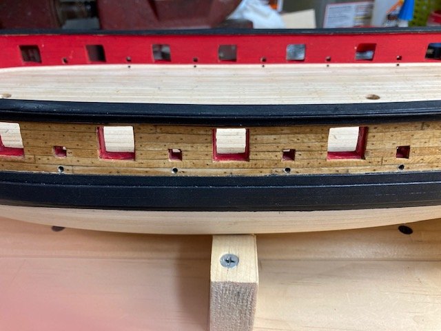
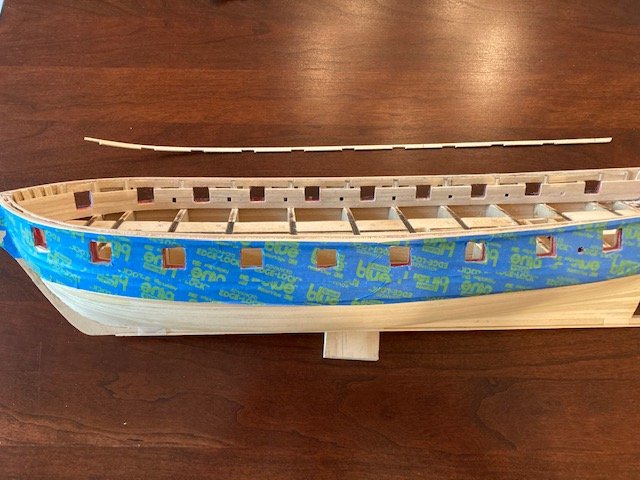
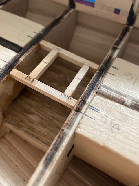
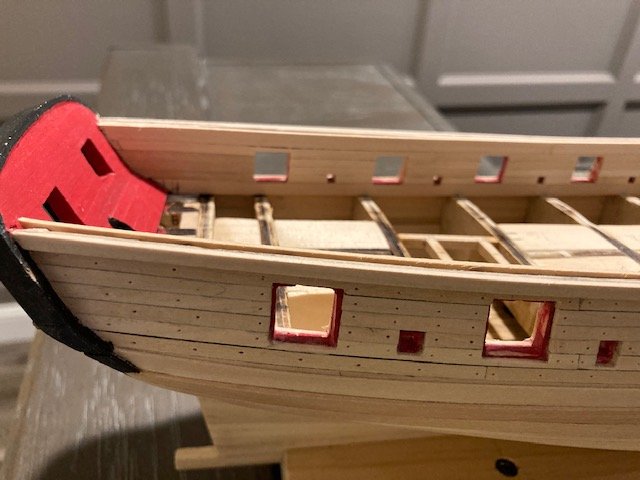
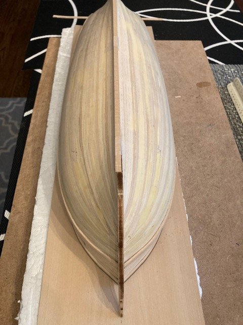
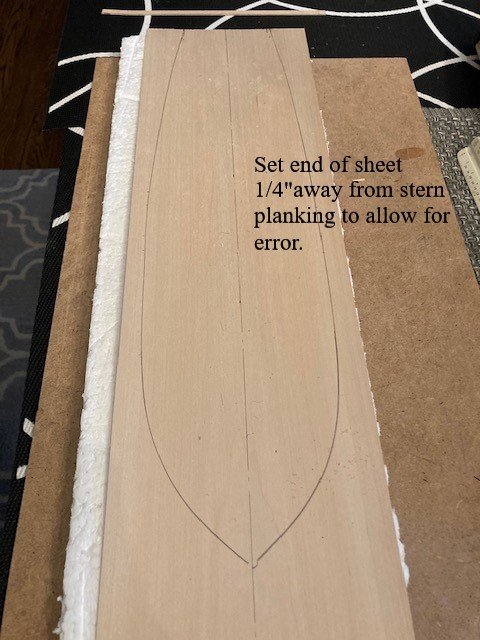
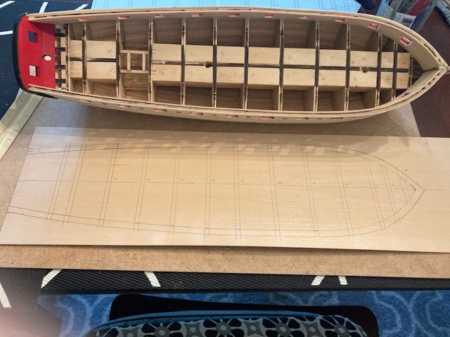
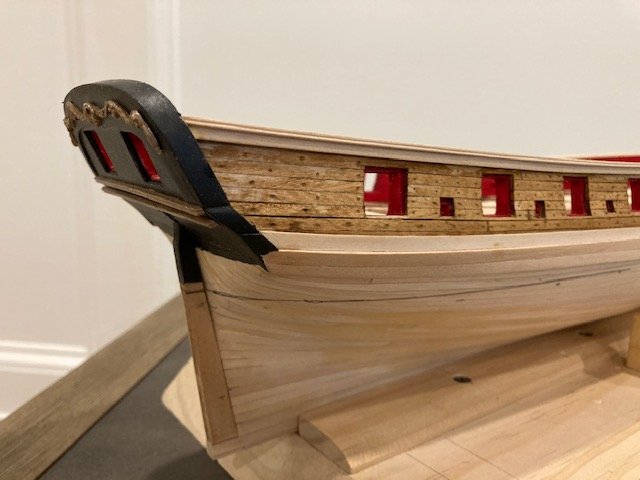
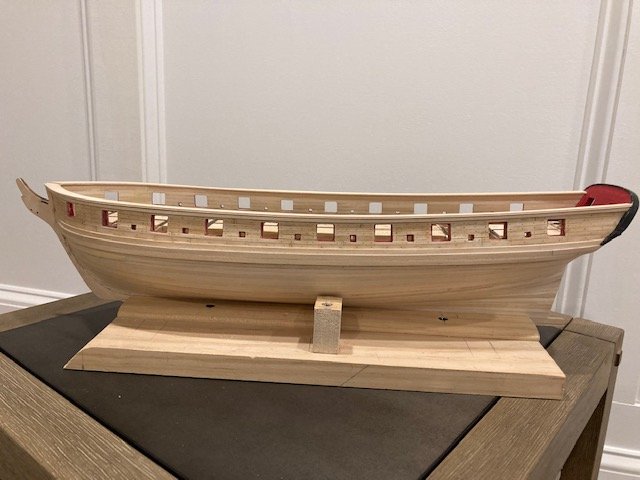
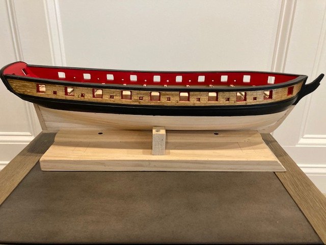
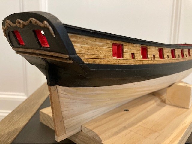
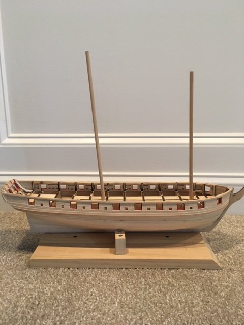
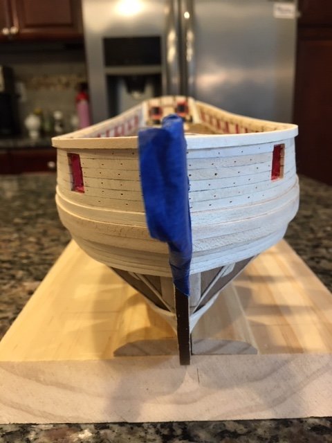
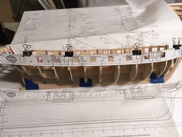
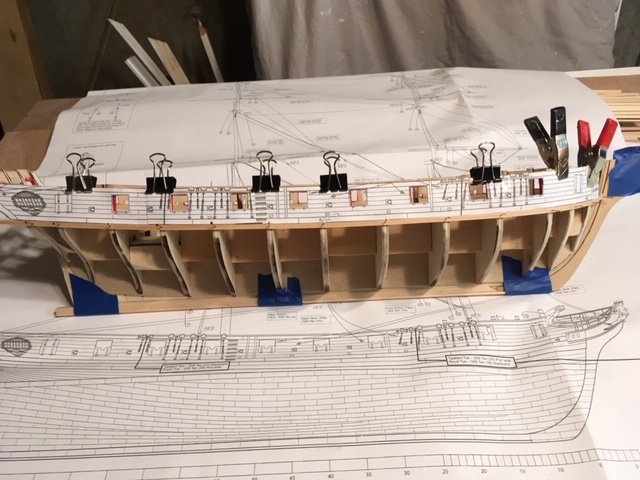
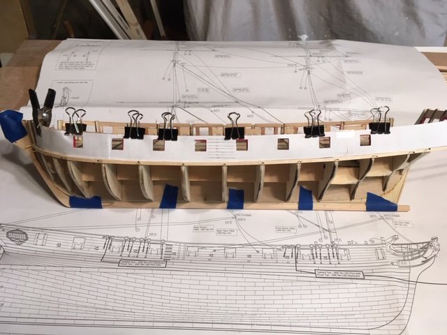
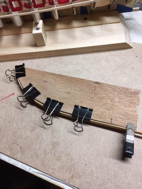
On to Chapter 7. Before starting the inboard planking, I added filler strips along the bulwarks at the stern. I test fit the first inboard plank (3/16” wide) to make sure that there was a 3/16” space between the top of the bulkheads and the gun ports sill. I had to do some sanding of the bulkheads to achieve the 3/16”. I soaked two 3/16” x 1/16” strips and clamped them to the jig. I installed each strip in one piece on the port and starboard sides. It’s difficult to measure the exact length of one piece. I used a piece of dental floss extended along the bulwarks at the deck level from the bow to the board stern plank. The bow end of the strip was cut on an angle and chamfered to mate with the bulkhead former. I then stretched the dental floss on the strip and marked the aft end of the strip. The aft end is cut on an angle to conform to the stern planking. I test fit the strip, glued it, and clamped it to the bulwarks. While waiting for the starboard side plank to dry, I framed the companionway (off ship) with 1/8” x 1/8” strips. I used the framing guide as a template. I marked the center of frame along the bulkhead former and used it to position the frame between bulkheads 16 and 20. Back to the inboard planking. I continued the inboard planking using 1/8” pieces left over from the hull planking. I used a 1/8” spacer inserted in the sweep port to keep all the sweep openings consistent. Rather than plank over the gun ports and cut them out later, I decided to cut each plank. The fourth 1/8” wide plank was notched out at the top of the gun ports (see photo). I had to use a 3/16” wide strip above the gun ports to complete the planking. The top of the bulwark is a uniform 1/4”, so the cap rail with molding strip will be 1/16” wider than the plans call for. The instructions say to cut the cap rail from a 1/16” thick sheet. The kit doesn’t include a 1/16” sheet of basswood. I found this out ahead of time from another build log. I ordered two 1/16" x 6" x 24" basswood sheets from Hobby Lobby. BTY, I avoid ordering from Model Expo because they charge a flat rate of $9.95 for shipping. Hobby Lobby charged $6.95 for shipping my basswood order. I made the cap rail in one piece by laying the ship on top of the boxwood sheet and then tracing the outline of the outboard bulwarks profile onto the sheet. I drew a parallel line ¼” inside the traced line. Then, I carefully cut the pattern out slightly outside of the traced lines with an x-acto knife. As it turned out, the port side cap rail was a little shorter than the starboard side, so I had to add a small piece at the stern. The mistake I made is that I set the basswood sheet against the stern planking. In hindsight, I should have allowed a ¼” or so from the end of the sheet. All-and-all, I’m happy with the way it turned out; and the small piece that I had to put in will be covered by the stern davit (Chapter 14). I made the 1/16” square molding strips that go along the outboard edge of the cap rail in same manner as the stern molding strips. To avoid breaking the molding strips, I soaked them and set them in the jig. Because the wood swells when wetted, I had to file out the grove again. With this done, I glued the strips in-place and secured them with clamps. I should have left a little space between the top of the rail cap and the top of the molding strip - the instructions don’t say to do this. I tried to align the top of the molding strip with the top of the cap rail. In some areas the molding strip ended up being slightly higher than the cap rail. The ramification of this is, when you sand the rail cap to even out the molding strip some of the molding strip profile is lost. I decided that the treenails that I made with a sharp pointed awl were fine and, therefore, did not need to be drilled. I did try to even each one out with the awl. Filled the treenails with Minwax Golden Oak wood putty. After applying the putty, I wiped the bulwarks with a paper towel to remove excess putty – I’m satisfied with the result. On to painting. Applied Minwax Pre-stain wood conditioner to the outboard bulwarks planking, waited two hours, and applied the first coat of Minwax Golden Oak stain. After five minutes or so I wiped the surface with a cloth to even out the stain. I repeated the process for the second coat. I’m satisfied with the finish. Before painting the cap rail, wales and sheer strake, and the hull to the water line, I applied a coat of polyurethane over the stain. I did this because I was concerned that the masking tape might remove the stain finish. I like the result. I will apply another coat later. Taking a break from painting, I pinned and glued the stern post to the hull. Cut the keel to length. Decide to jump ahead to Chapter 8 and work on the rudder. I added a length of 3/16” x 1/16” wood strip along the bottom of the rudder and then filed the rudder down to establish the 1/8” taper on the aft-most edge. Beveled the forward side of the rudder on both sides – I think some of the detail will be lost when the rudder is covered with copper. While studying Plan Sheet One, I discovered that rudder opening profile has a flat edge, so I refined it by filing it to match the plan. I test fit the rudder - everything fits fine. Back to painting, I masked the bulwarks and the hull with Frog tape (the contrast with the red paint looks like a Christmas theme color) and applied three coats of Model Expo MS 4830 Hull Spar Black to the cap rail, wales and sheer strake, and the hull to the water line, light sanding between each application. Overall, so far, so good. Next up, deck planking.


- 157 replies
-
- 5
-
-
- model shipways
- syren
- (and 1 more)
-
Thanks. Each build is a learning process. I review other build logs for ideas and comparisons.
-
I’m at the painting stage now. I’ll post when I finish that stage. Then, on to deck planking. I’m enjoying this build.
- 157 replies
-
- 2
-
-
- model shipways
- syren
- (and 1 more)
-
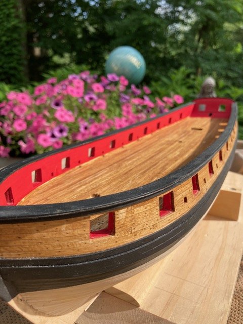
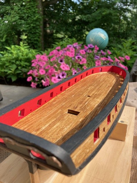
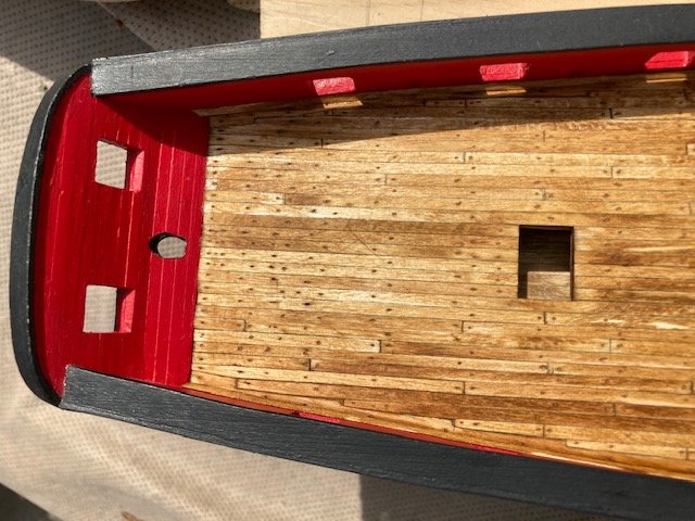
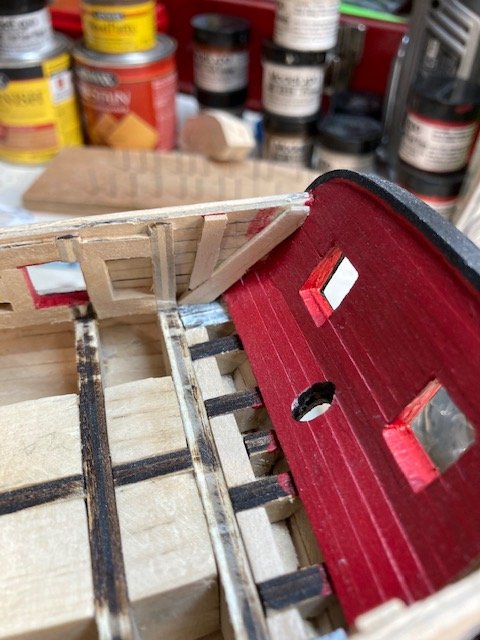
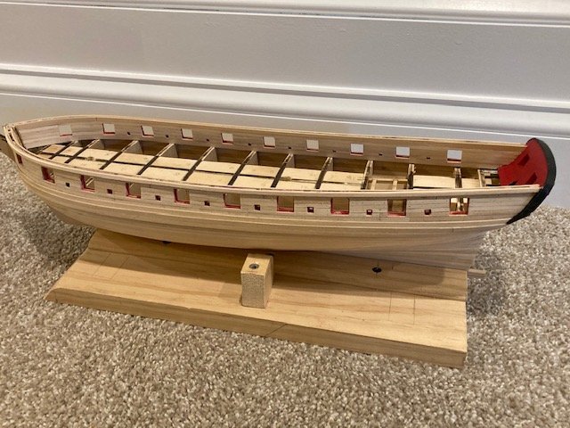
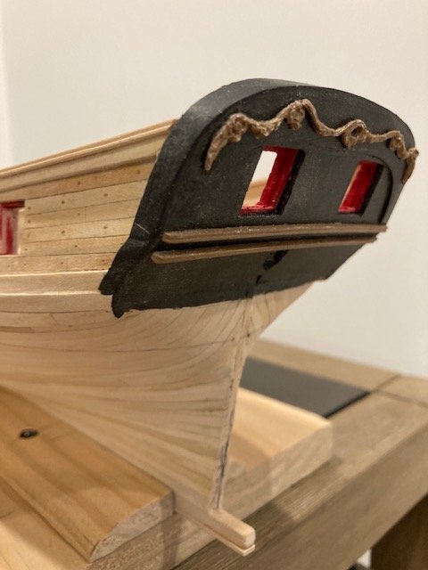
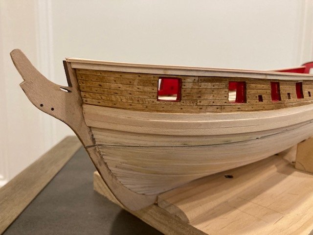
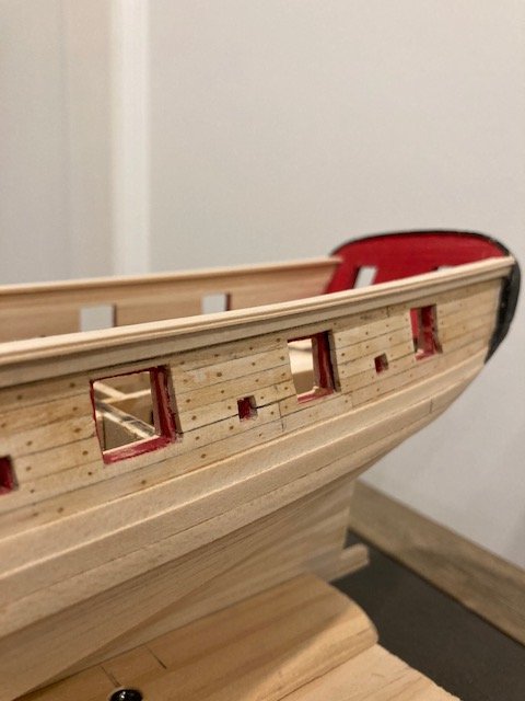
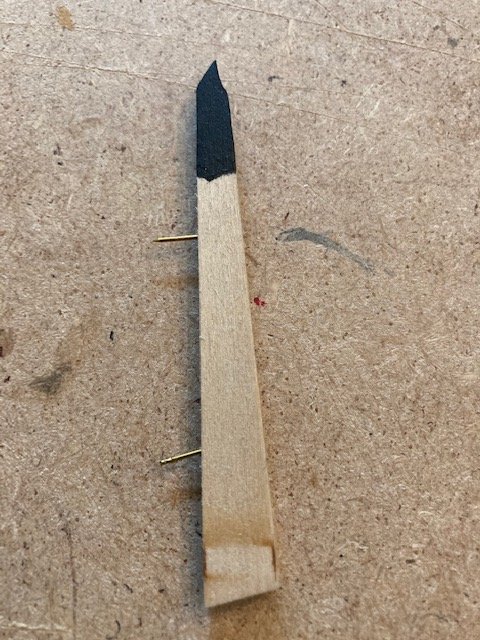
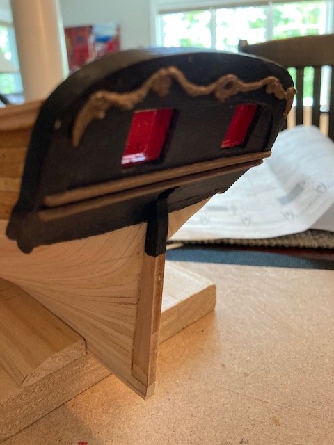
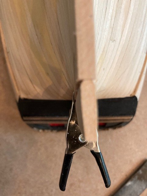
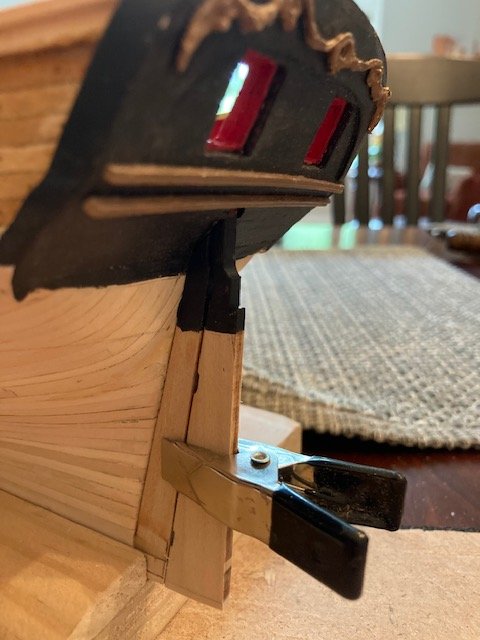
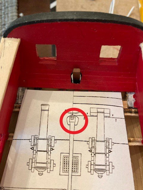
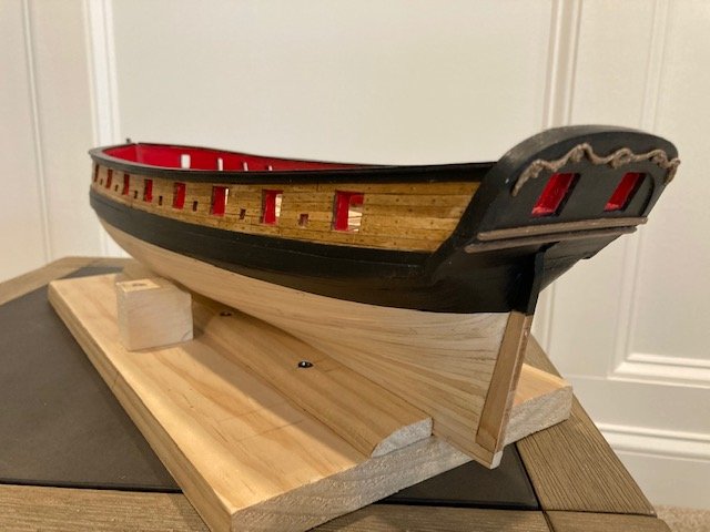
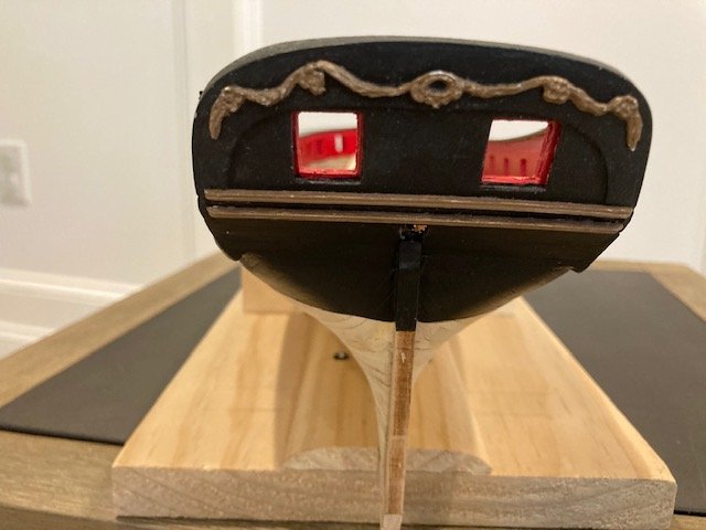
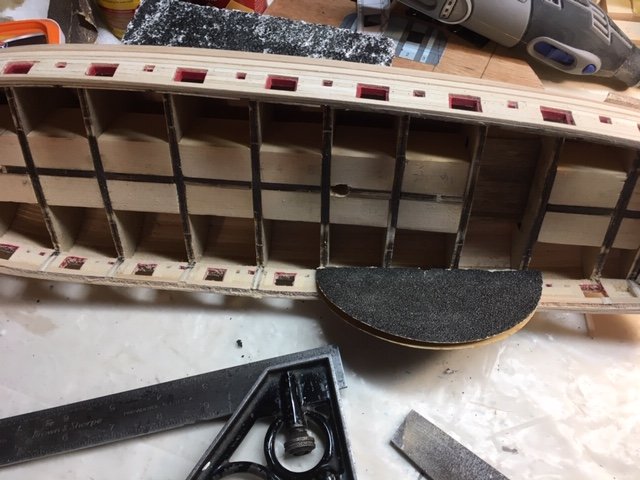
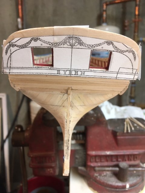
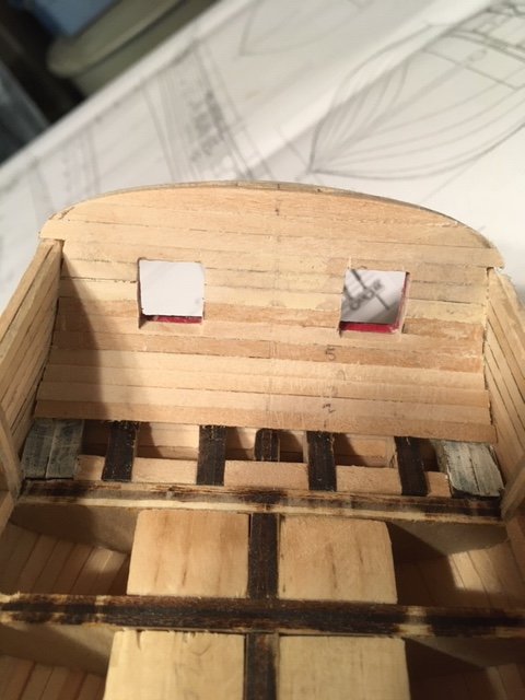
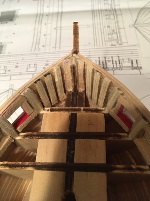
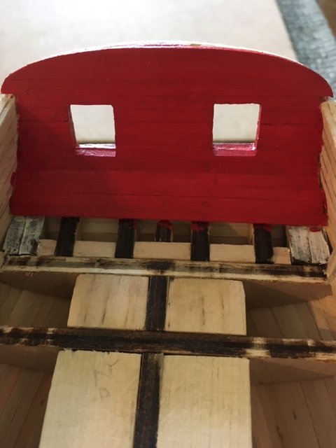
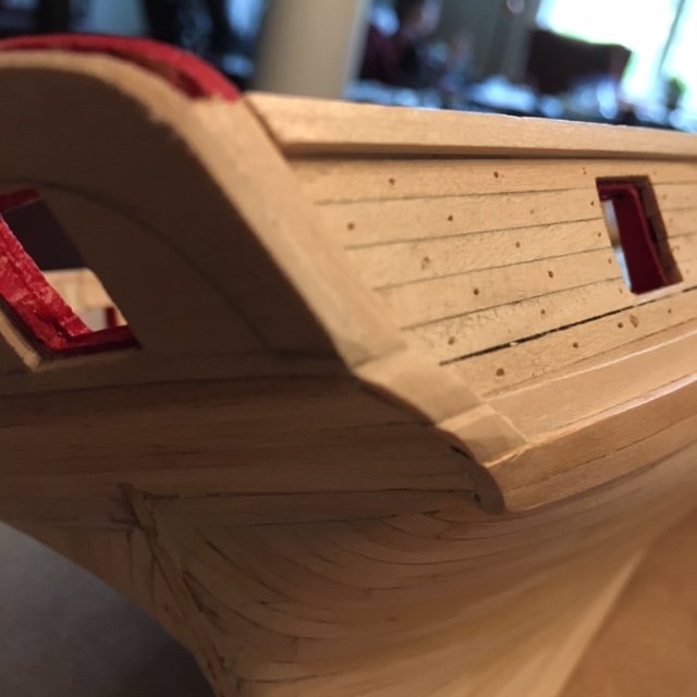
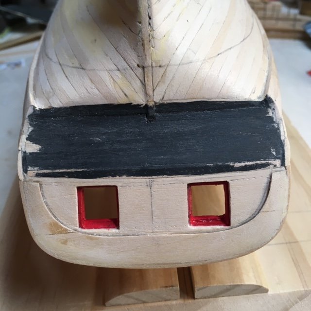
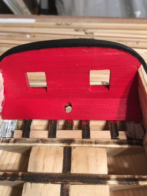
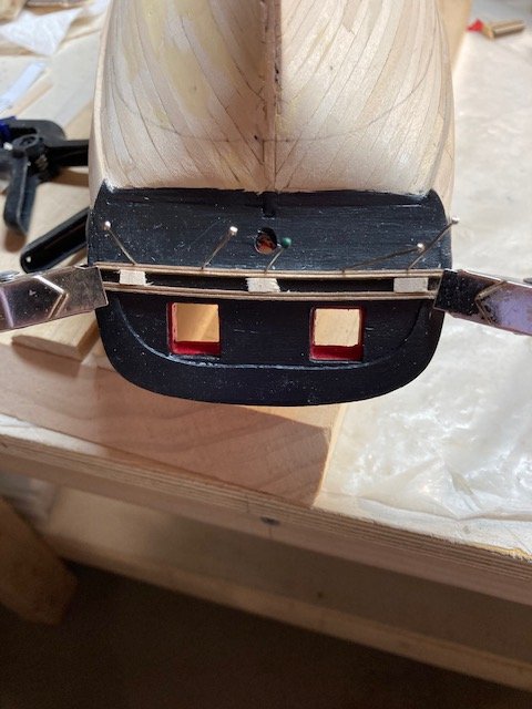
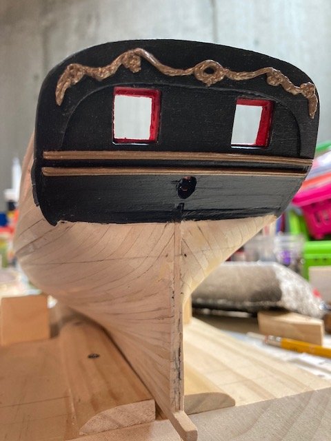
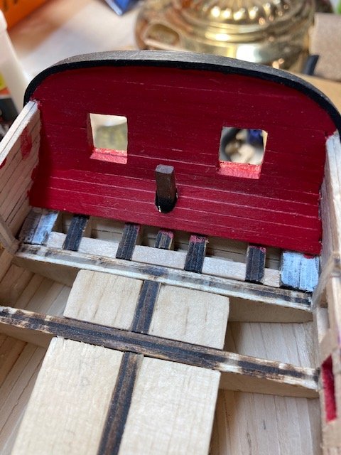
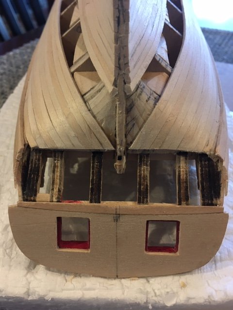
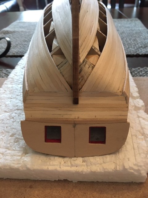
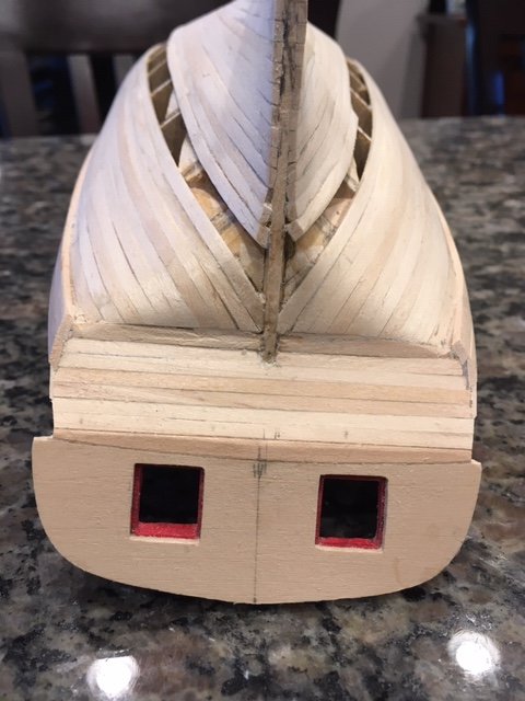
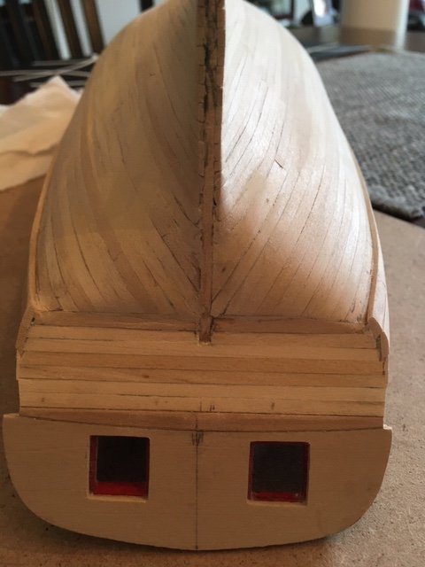
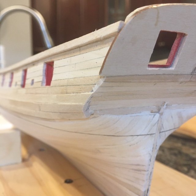
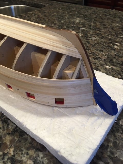
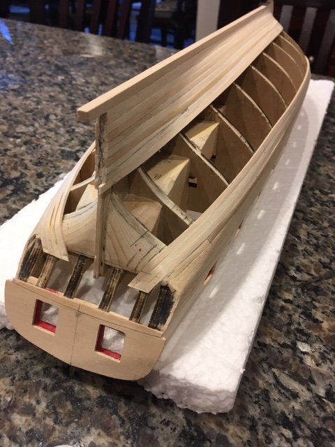
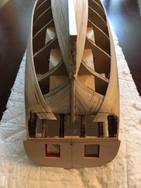
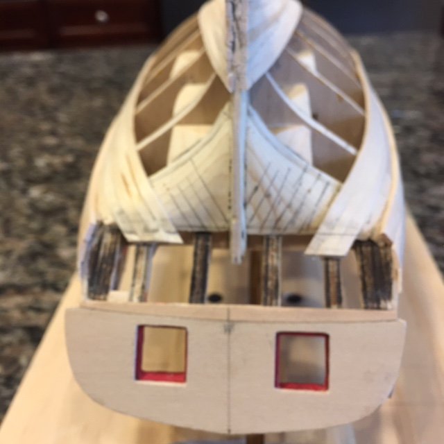
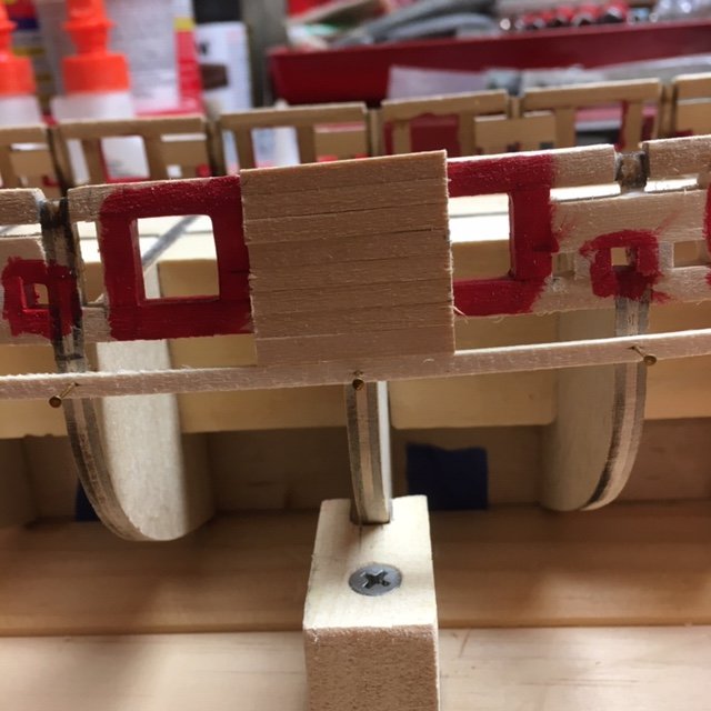
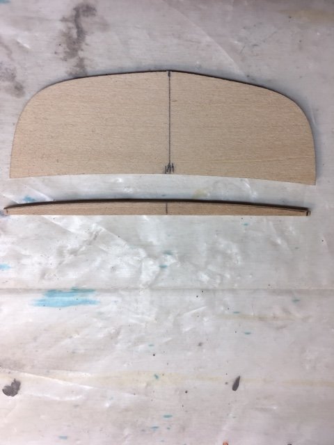
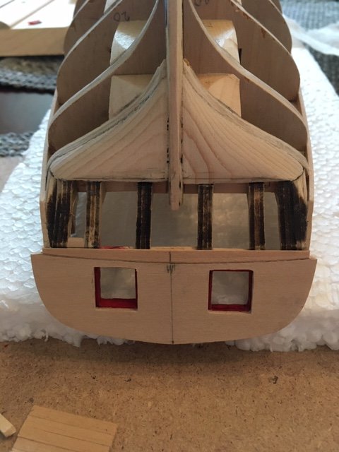
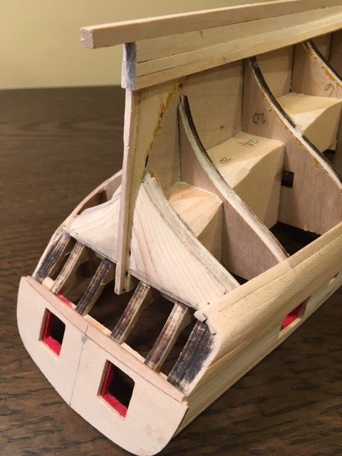
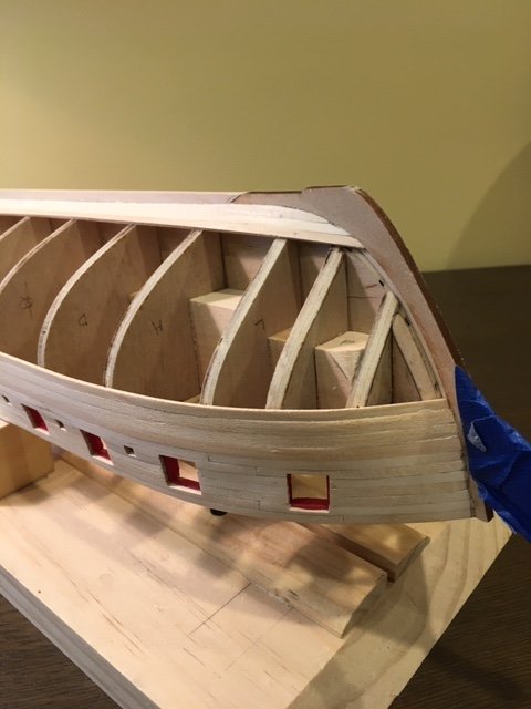
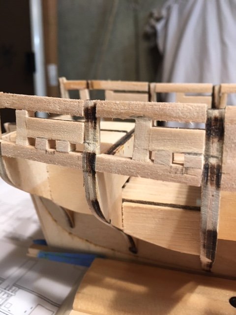
Completed filling and sanding the hull to the point where I’m satisfied that it’s suitable for attaching the copper plates. On to Chapter 6. I decided to hold off staining and painting the hull and bulwarks. I still need to drill the treenails and fill them with Minwax Golden Oak putty. After reading some build logs, I purchased some Minwax Pre-stain to prevent blotchiness when the Minwax Golden Oak stain is applied. I will be using Model Expo MS 4830 Hull Spar Black to paint the sheer strake and hull wales down to the water line. I sanded the stern down to 3/32” thick using my Dremel, file, and sanding blocks. I decided to jump to Chapter 7 and thin down the bulwarks before installing the inboard stern planking. I made a pencil mark on the top of the bulwark and then applied painter’s tape along the line to serve as a guide, and to also protect the sheer strake. I started thinning the bulwark with my Dremel and then switched to sandpaper. I found that a 5” diameter 70 grit sanding disc folded in half was perfect for thinning down the bulwarks. I used a long file to even out the bulwarks. With that done, I decided to test fit the second layer laser cut transom piece. But, first I made a copy of the stern elevation on Sheet One, cut out the transom and taped it to the stern. As the instructions say, the laser cut piece is little taller – actually much taller - and will need to be sanded down. I cut out the stern gun ports on the copy of the stern - they match up well. I taped the laser cut transom piece to the stern and outlined it with a pencil. I neglected to remove the transom piece and, consequently, it broke while I was thinning the bulwarks. I glued it together with CA. Since the transom is not painted, I’m concerned the break lines will be visible. Ugh, I’ll deal with it later. Meanwhile, back to Chapter 6. I cut, trimmed, fitted and glued the 1/8” x 1/16” inboard stern planks and painted them with three coats of bright red paint (ModelExpo MS4835). I added some filler blocks at the bow to achieve a uniform curve and to secure the bulwark planking. Built up the sides of the stern transom, port and starboard, with 5/32” x 1/16” basswood strip as per the instructions. Sanded it down to match the curved profile of the stern transom. I fashioned the two (2) transom molding strips from 5/32” x 1/16” basswood strips, following the photo on Page 26 of the instructions. Next, the two upper counter molding strips. I made a jig (see photo) for the molding strips using a cutout of the stern. Before soaking the strips, I added a profile to the 1/16” x 1/16” basswood strips by scribing the strip with the fine point of an oval needle file (my late Father was a tool maker, so I have a collection of needle files). After soaking, I placed the molding strips in the jig and let them dry overnight. I didn’t thin down the strips as the instructions say because I like the look of them as they are. I went out-on-a-limb and painted the molding strips gold. I plan to paint the stern decorative carvings gold, too. Before gluing the molding strips in-place, I decided to fit the transom cap. I soaked the ¼” x 1/16” x 24” basswood rail cap strip overnight. I cut a length of strip long enough to wrap around the transom, preformed the strip with my fingers, and attached it to the transom with clamps. The first attempt resulted in the strip breaking. I cut another length and wet it under the sink faucet with hot water. This yielded a better result as I was able to clamp the strip to the transom without it breaking. I decided to use the broken transom piece and to paint the transom black a la rafine’s and Dubz build logs. I like the contrast of the gold moldings with the black counter. I glued the stern cap rail on in one piece. The cap rail overhangs the stern inboard but not outboard – no big deal. Next, the fashion pieces were cut, shaped, and glued in-place. After some fine sanding, the rail cap, fashion pieces, and transom were painted black. I glued on the stern molding strips, making sure to provide at least 1/8” separation between them to accommodate the photo etched letters SYREN. I went ahead and painted the cast decorative carvings gold and glued them to the stern. I painted the SYREN letters white. I’m holding off on installing the letters until I can figure out how best to do it. I jumped ahead and drilled the opening for the rudder. To get the approximate location, I test fitted the stern post and measured the distance (4’ @ 3/16” scale) from bulkhead 26 to the rudder on Plan Sheet One. I drilled a small pilot hole first and then reamed it with increasingly larger bits up to 7/32”. I had to file the opening to fit the rudder. This completes Chapter 6.
- 157 replies
-
- 5
-
-
- model shipways
- syren
- (and 1 more)
-
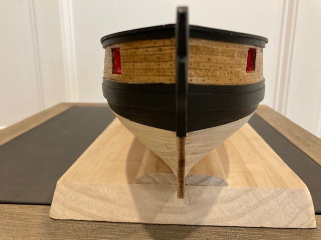
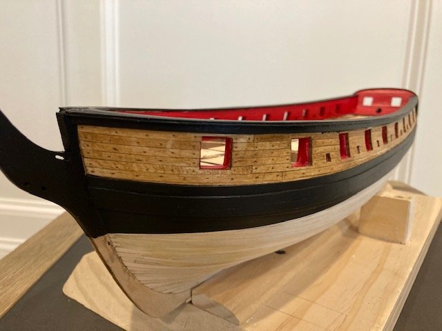
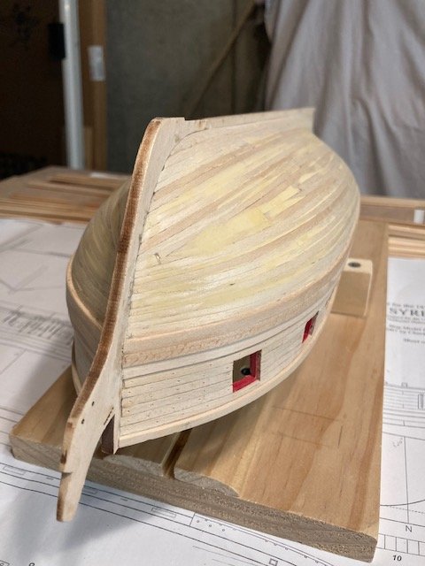
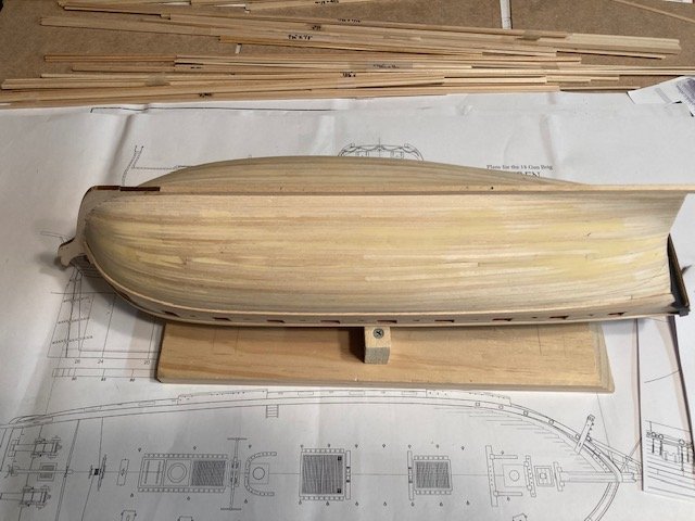
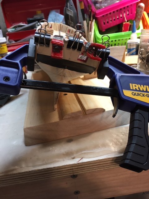
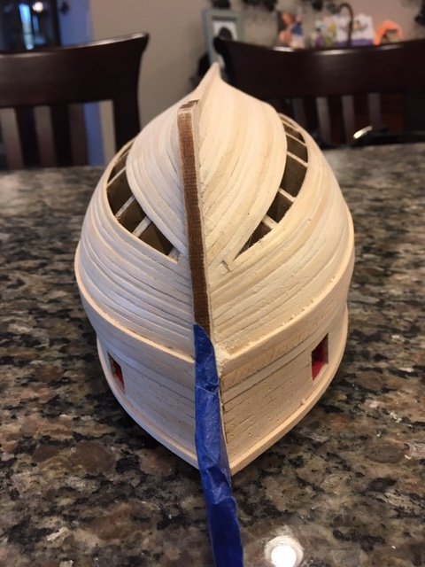
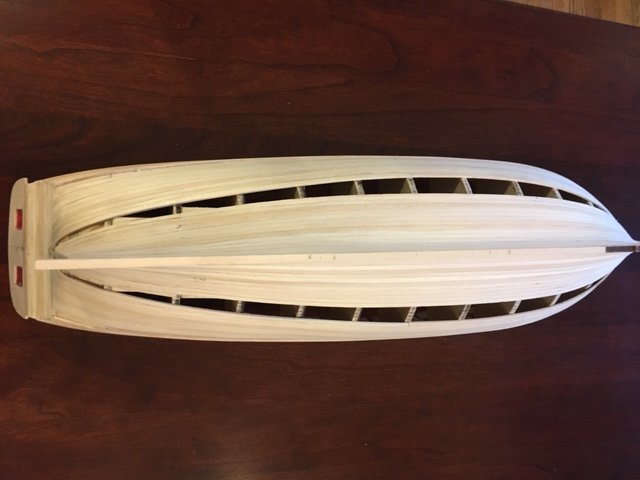
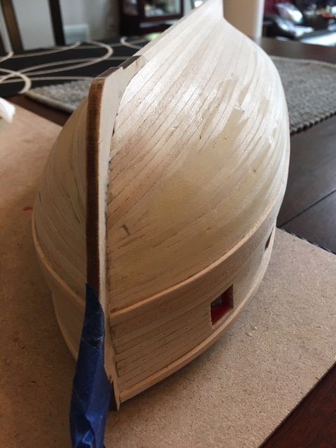
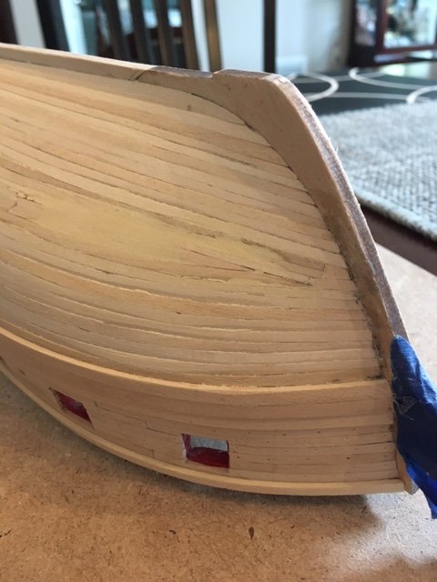
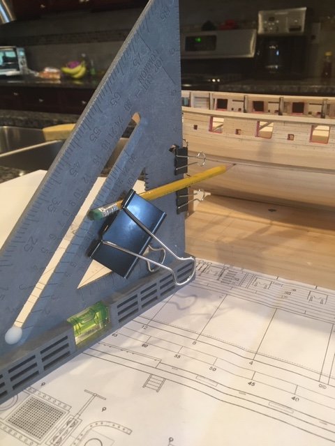
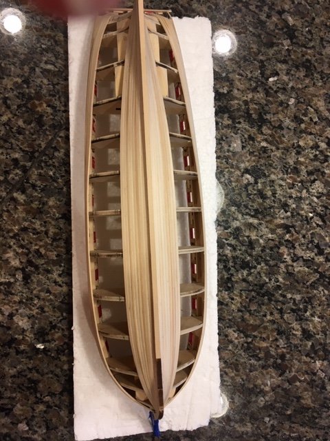
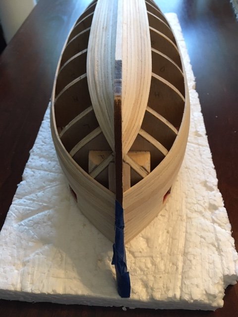
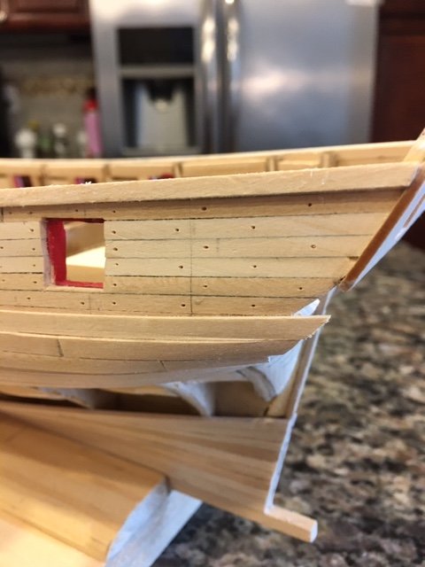
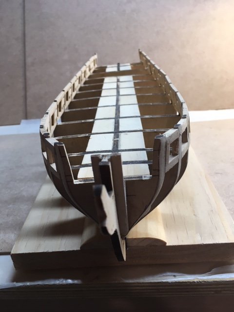
On to Step 6 of Chapter 5, completing the hull planking. I've been tapering the planks down to 3/32" about 4” to 5” from the bow. I marked the knee stem in 3/32” intervals as a guide. I typically taper 2 at time. After tapering, I lay them down side by side to check for uniformity. I run a file across them to even them out. At the bow, I cut the end of each plank at an angle to follow the curve of the stem and then chamfered the angle cut so the planks fit nicely in the rabbet. I soak them (in the bathtub) for at least 30 minutes and then attach them to the hull temporarily with push pins, Acco clips, and clamps. While the planks are drying, I continue the process. When the planks are dry, before gluing them in-place, I moisten the end of the plank at the tuck of the stern to prevent the plank from splitting. I secured the plank at the stern with my trusty Irwin Quick-Grip clamp. I’ve been alternating planking up from the keel and down from the wale on the port and starboard sides with the goal of meeting in middle. The full planks at the stern are lay nicely over the counter without having to taper them. The planking started to droop at the stern, so I Installed a half stealer 6 planks up from the garboard on the port and starboard side. As I continued planking down from the keel, I installed a full stealer 2 planks from the half stealer. The planking developed a “clinker built” look, where the lower edge of the plank bulges. From what I have seen from other build logs, this is not uncommon. I probably should have spiled the planks at some point, but I continued planking. This being my second POB build, my goal was to improve my planking skills and strive to complete the hull planking without having to use wood filler and to limit the amount of sanding. Because the planking developed clinking, I had to use wood filler to even out the planking and provide a smooth surface for the copper plating. In spite of this, I’m satisfied with the hull planking. And, I learned to make stealers, something I didn’t use on my last build. Decided to complete the counter before finishing the hull. For me, it was easier to add the counter after the stern planking was complete because I didn’t have to cut the planks that tuck over the stern to the exact length to butt up against the counter plank. I test fit the counter planks before cutting off the stern planks - I had to add 1 more counter plank than the instructions call for. I scribed a line across the stern planks at the top counter plank and cut them all to length with a mini saw. Some sanding and filing were required to even out the surface of stern planks and the counter planks. I’m satisfied with the way the counter came out Back to the hull, the closing pieces were tricky. I used a several drop planks to reduce the number of planks at the bow, a 5/32” wide correction plank, half stealers, full stealers, and a spiled plank. I’ve been using carpenters glue, but where I couldn’t hold the planks down with clamps, I used CA glue to tack the plank. Then I worked back with carpenter’s glue on the bulkheads and the edge of the planks. To fill the final gap, I tapered and fitted a “correction plank.” At the stern, I used a 5/32” wide closer plank tapered to fit the gap at the stern post on the port and starboard sides. I’m satisfied with the hull planking. Although, I’ll have to do some more filling and sanding to prep for the copper plating. Marked the water line per the instructions. I crafted a water line marker from a speed square and Acco clips. I’m holding off on installing the laser cut stern post until I paint and stain the hull. Aside from that, Chapter 5 is complete. Oh, and I drilled out the pilot holes in the deck for the masts.
- 157 replies
-
- 5
-
-
- model shipways
- syren
- (and 1 more)
-
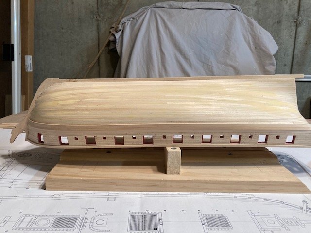
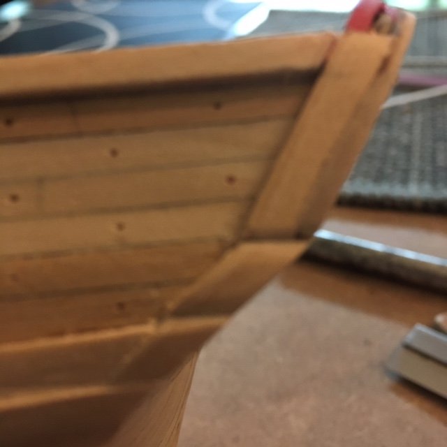
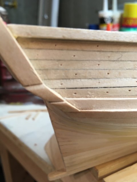
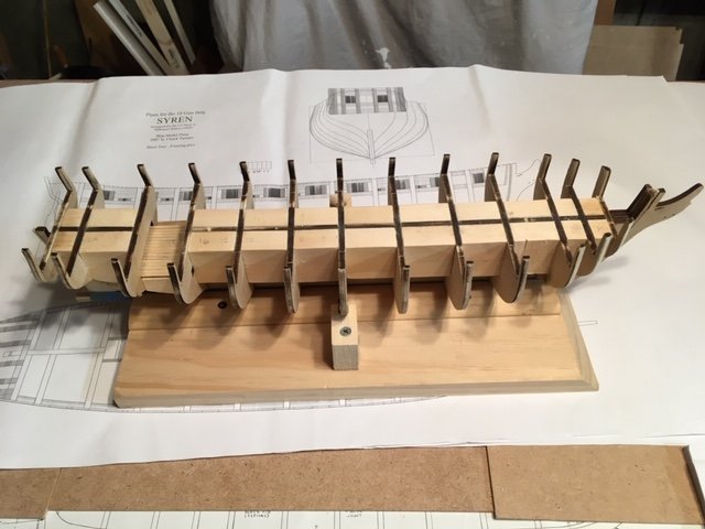
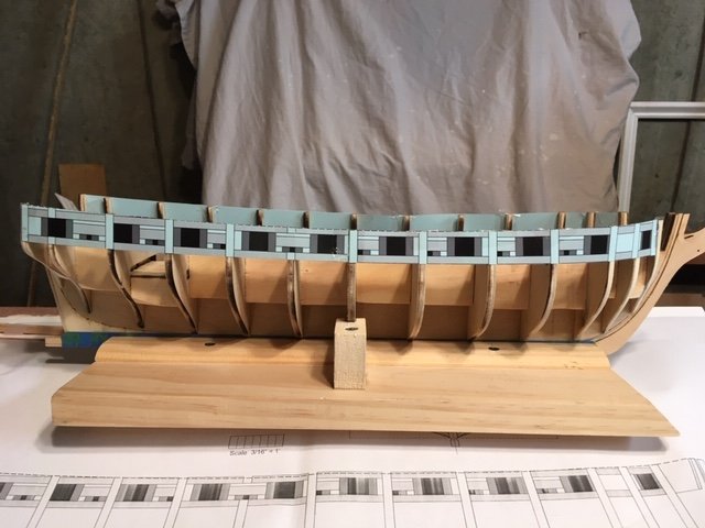
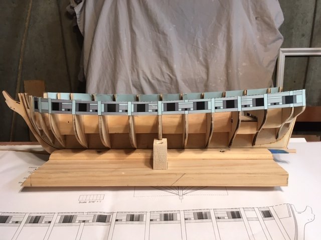
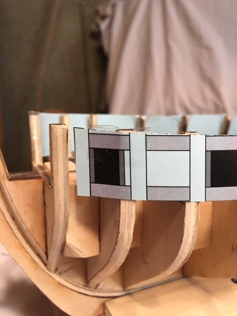
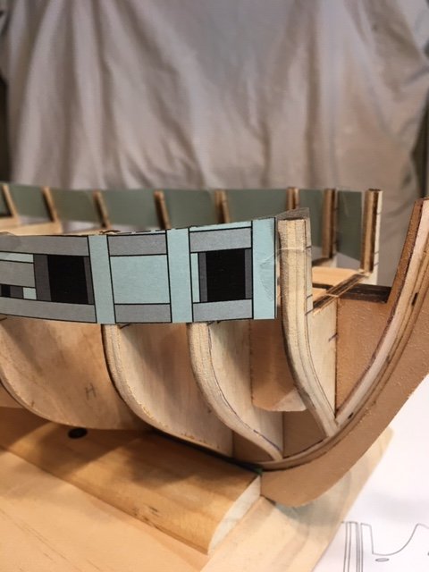
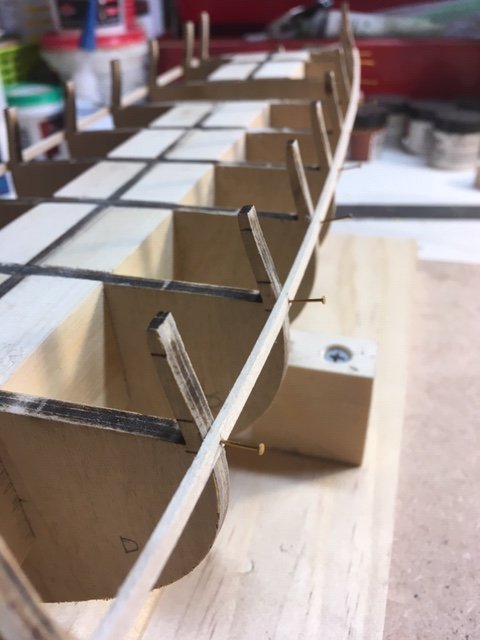
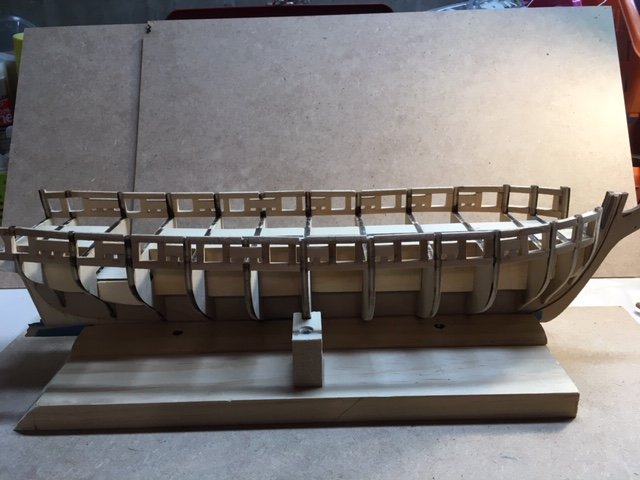
On to Step 4. Measured the gap between the 1/8” wale strip and the 1/8” keel strip and determined that twenty-two (22) 1/8” strips will be required to fill the space. This compares favorably with the 22 to 23 planks in the instructions. So far, its true to form (see photo). Next, I measured the gap at bulkhead “N” and divided it by 22 strips to determine the width of each plank at the bow. Each plank will have to be tapered to about 6” at 3/16” scale, which is roughly 3/32”. I measured the distance along the stern post and under the counter using a piece of dental floss. Stretched out, the corresponding length of floss is +/-29” at a 1/8” scale. So, around 29 planks will be required to cover the stern area. Added 4 planks below the initial 3 under the wales on the port and starboard sides. After tapering, I soaked the planks in water and attached them to the hull temporarily with push pins, Acco binder clips, and clamps. I held the planks in-place at the stern with an Irwin Quick-Grip clamp - this is the most difficult area for securing the planks. The plank formed nicely with the counter, which eased the horsing of the plank around the counter. I left the planks longer at the counter, as I will cut them later when I install the counter planks. Note: The Acco binder clips shown in the photo were made by taking the arm from one clip and inserting it into another clip. I got this Idea from rtopp's Syren build log. These clips are very useful. Like he and some other builders I purchased the MS planking clamps (for my prior build) and found them useless. At the keel, I added 5 planks on each side in addition to the initial 3. I added a stealer, cut into the 4th plank on each side – these are tricky. I did some initial sanding while waiting for glued planks to dry. Completed the second layer of the wales (2 - 5/32” x 1/16” thick lower wales and 1 -5/32” x 1/32” thick upper wale) and the sheer strake (1/8” x 1/32” thick). Like the planks, I cut the wale strips on an angle and chamfered them to fit into the rabbet at the stem. I preformed them by soaking them in water then clamping them to the jig. The wale strips were glued on top of the first layer of wales and held in-place with clamps and clips. I left the wales and sheer strake longer at the counter, as I will cut them later when I install the counter planks. Next, the treenails. I followed the instructions and lightly drew some vertical lines on the planks representing the center of each bulkhead. I used an awl to mark each treenail, following the general pattern shown in the photo on Page 24 of the instructions. The holes will be drilled later with a .55 mm (0.0217”) bit and then filled with Minwax Golden Oak wood putty. I made a test sample to see how the treenails will look after puttying and then staining with Minwax Golden Oak stain. Whence the treenails are drilled, I think the combination of the Golden Oak putty and Golden Oak stain will be okay. As a general note, the treenail pattern is a matter of personal design and consideration for what was common practice in ship building in the 17th century. I'm satisfied with the treenail pattern. Except for the counter at the stern, which I opted to hold-off on completing, the model is complete through Step 5 of Chapter 5.
.JPG.9d288dee1cf4e31beb5f1f080f6091ed.JPG)
- 157 replies
-
- 8
-
-
- model shipways
- syren
- (and 1 more)
-
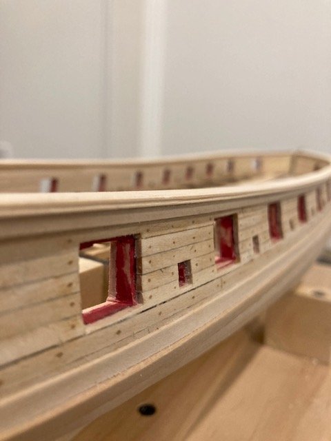
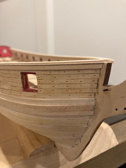
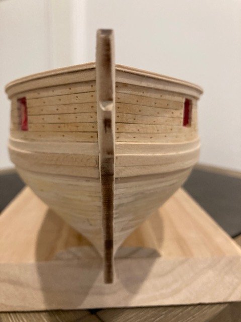
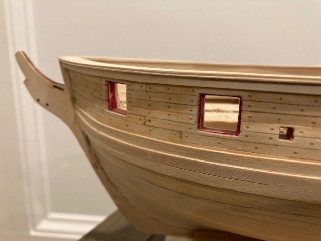
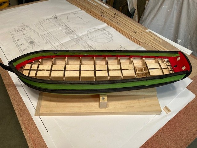
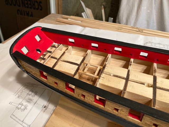
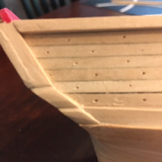
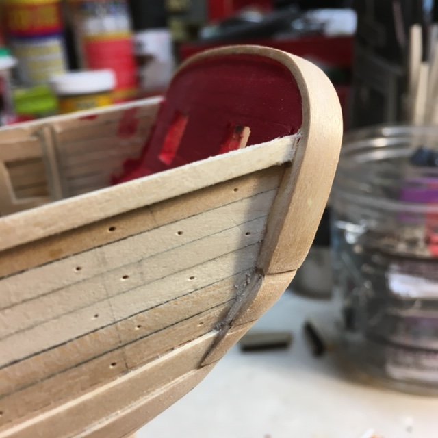
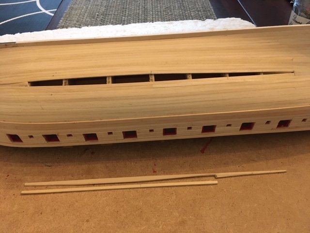
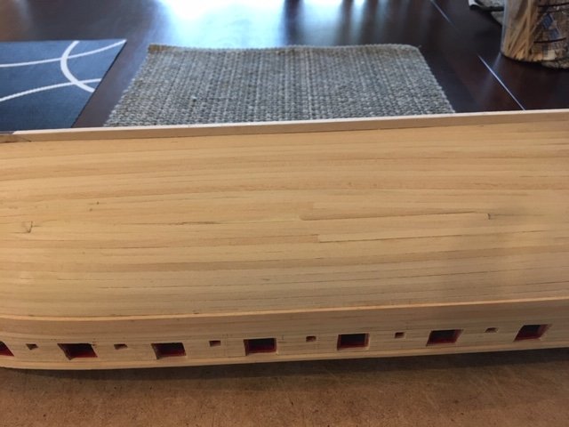
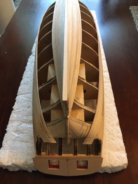
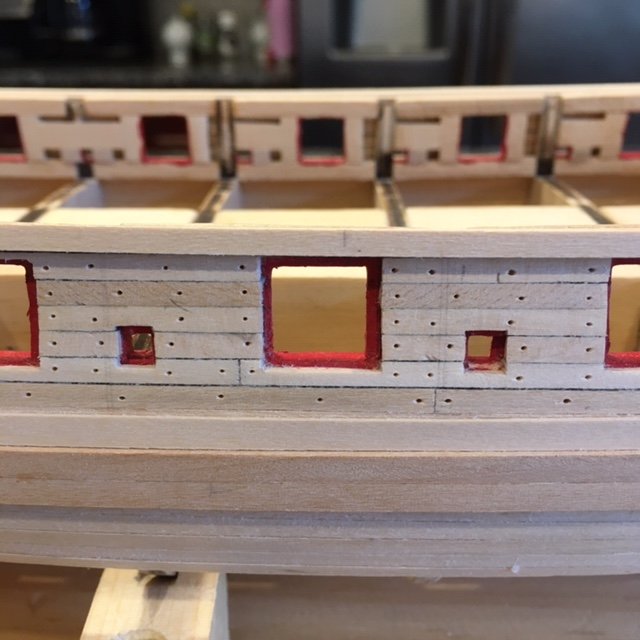
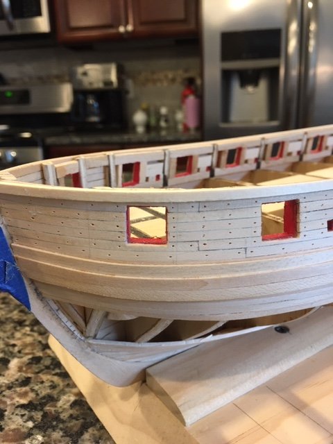
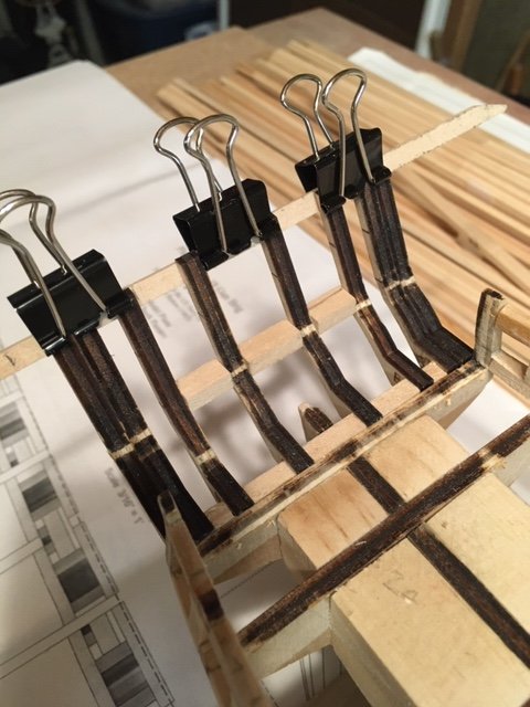
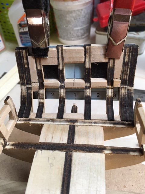
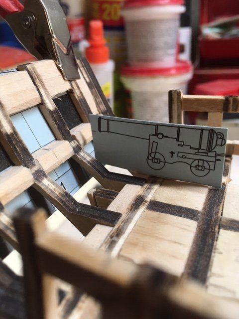
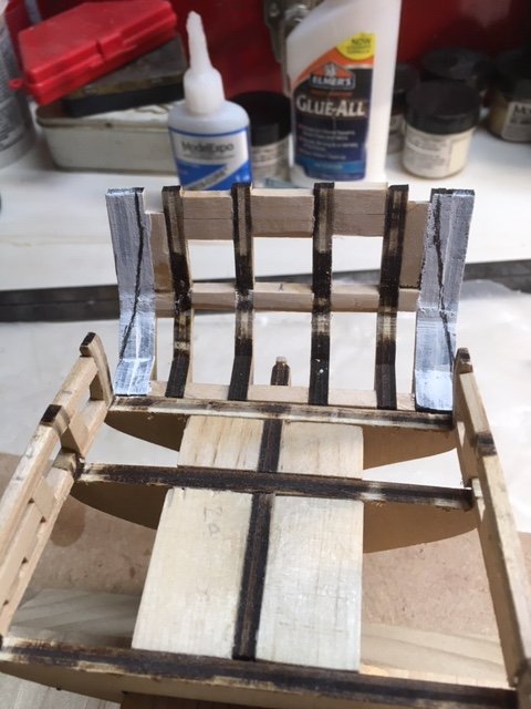
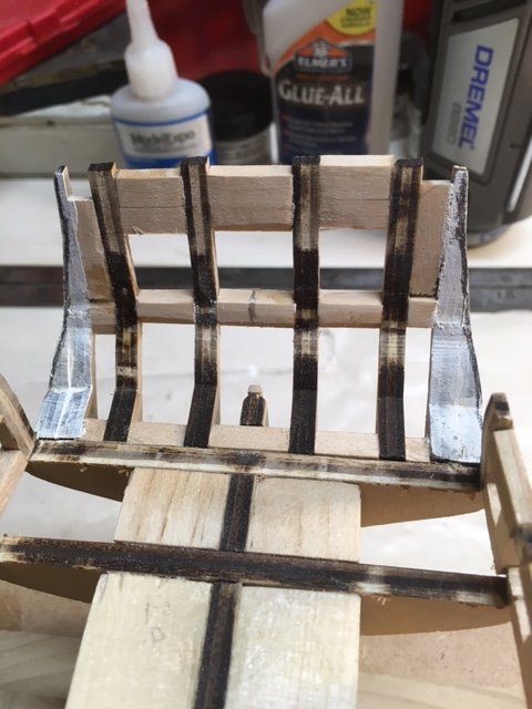
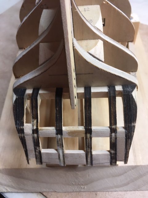
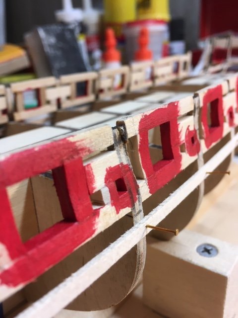
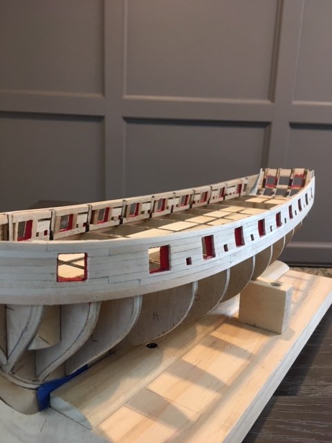
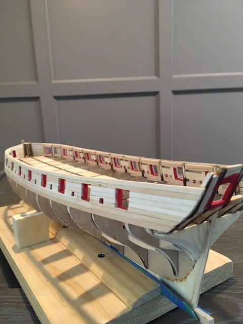
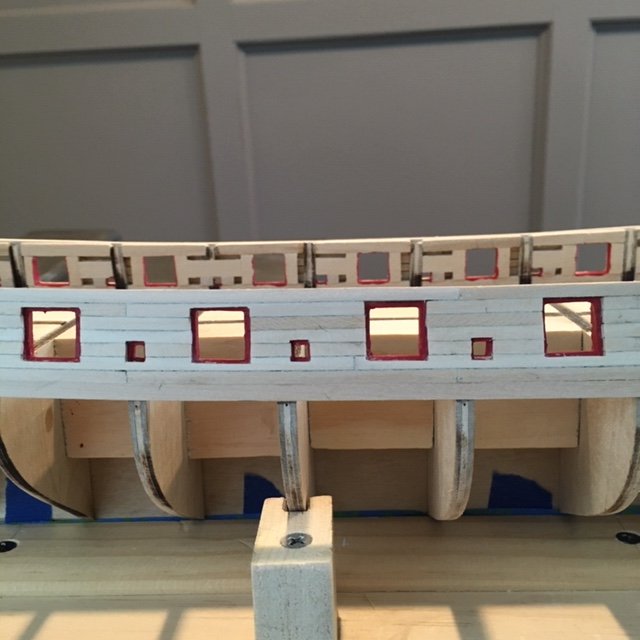
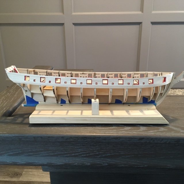
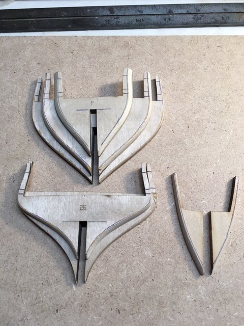
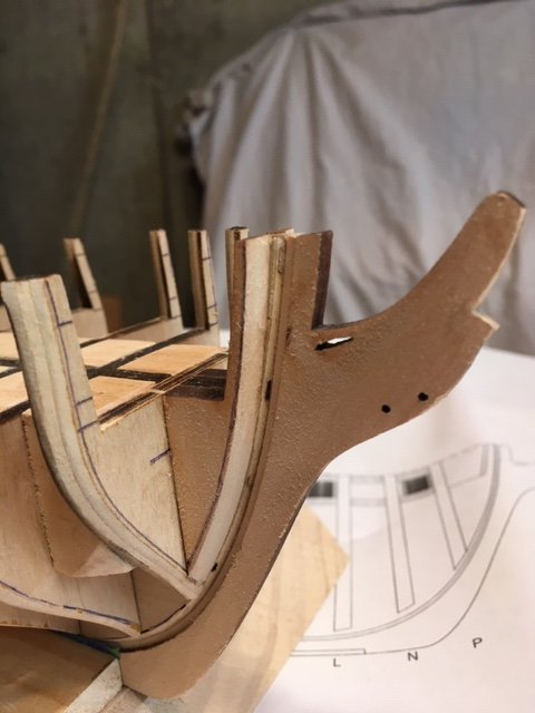
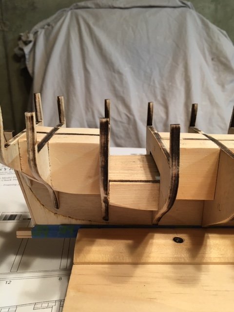
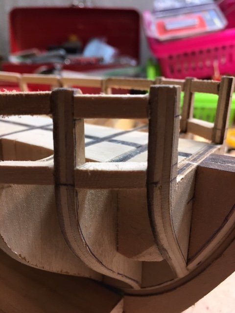
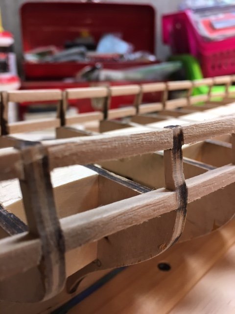
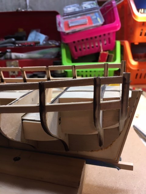
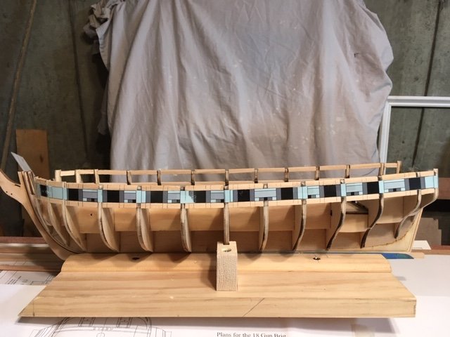
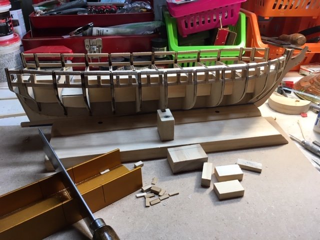
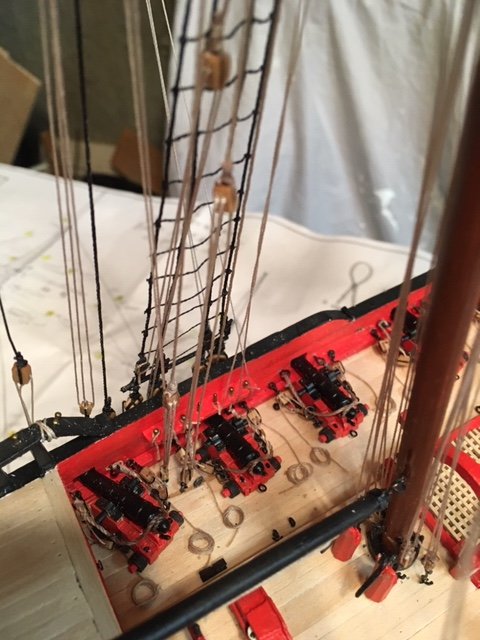
Now onto Chapter 4. I completed the stern port frames – no problems. I deviated from the instructions somewhat. I glued fillers #2 in place before gluing stern frames A in place. This supported the A frames while they were glued in place. I did the same with fillers #3. I attached a batten to the tops of the frames to secure them in place while the glue was drying. Next, I glued the C frames together and allowed them to dry before gluing them to the stern. While waiting the C frames to dry, I did more sanding of the bulwarks,trying to keep the contour of the bulwark stanchions. With C frames dried, I glued them in-place. I measured and cut the port sills from the 3/16” x ¼” wood strips and glued them in place, making sure that they are level. I set them at the laser burn marks on the inside of the frames. I added the gun port lintels and the rest of the filler blocks as per the instructions. I used my 15/32” block to establish the height of the gun port lintels. I checked the accuracy of the marks by attaching the stern template. The burn marks and template were spot on. I cut out the cannon template to double check the height of the sills - I allowed 1/16” for the deck planks. The cannon barrel just clears the gun port sill. There’s no definitive height for the cannon barrel above the gun port sill – it only has to clear the sill. I sanded the blocks flush with the inside and outside of the stern frames. As the instructions state, the stern frames are fragile, so use care so as to not sand too aggressively. I marked the outside frames with a pencil to establish the shape of the stern. Prior to doing that, a la _SalD_ build log, I painted the C frames white to better see the pencil marks. I then trimmed the frames to the pencil mark, using my Dremel first and hand sanding last to fair the shape of the stern. I decided to make two solid filler pieces for below the counter rather than using the two strips as shown in the instruction manual. I made them from some scrap pine. I developed the rough shape of the fillers before gluing them in place. When I was satisfied with the rough shape, I glued the fillers in place. Whence the glue was dry, I did some final sanding – I’m sure I’ll have to do some more shaping. Moving on to Chapter 5, I applied two coats of bright red (ModelExpo MS4835) paint on the gun ports and the sweep ports. Deviating from the instructions, to locate the upper wale I opted to make a copy of starboard side elevation view on Sheet 5 and to cut out the bulwark. I used this as a template to locate the bottom of the upper wale. I realize that there is a slight enlargement when making a photocopy but in spite of that, the template aligns almost perfectly with the gun ports (see photo). That being said, I decided to attach a batten to the hull as a guide for the placement of the upper wale. As I noted, the top of the batten will be the bottom of the upper wale. I repeated the process port side using the opposite side of the template. Again, the template aligned almost perfectly with the gun ports. As expected, the top of the batten is below the burn marks on the hull which represent the top of the wale (see photos). As a check, I made a mockup of the seven 1/8” and one 5/32” planks and placed it on top of the batten. It aligns fairly well. I made some slight adjustments to the batten. I’m satisfied that this is about as accurate as I will get with the location of the upper wale. Next, I made a jig for the wale strips using a photocopy of the deck Layout as a template. I soaked the 5/32” x 1/16” strips for the upper wales in water for about 20 minutes and then clamped them to the jig to preform them. I attached the starboard side upper whale with glue, pins, and clamps. I used nails because the upper wale with be covered with a second wale. Before planking the bulwark, I preformed the 1/8” strips in the jig. I was able to preform three at a time. I started planking the starboard bulwark beginning at the bow. The first two rows of planking were cut into segments. I used the elevation view on Sheet 5 to determine were the joints are. The most difficult part for me was holding the first plank of each row in the rabbet at the knee stem. I placed a clamp on the knee stem to hold the plank against the bow filler. The second row of planking had to be cut out at the gun and sweep ports. I scored the plank with the knife blade where I wanted the notch for the gun port or sweep port and then made a sawcut to the depth of the notch. Then, I removed the notch and finished it with a small file. Above the second plank, the planks were cut into small short lengths between the gun ports and the sweep ports. When I reached the top of the gun ports, before adding the sixth plank, I filed the ends of the planks with a small square file to achieve an even edge along the lip of the gun port. I found it difficult to get an even edge on the sweep port lips. The gun port lips are not uniform 1/32” wide around each port, but to the naked eye I don’t think it will be noticeable. The sixth row of planking was cut into segments, again using the elevation view on Sheet 5. These planks had to be notched out at the gun ports. Before gluing them, I paused to consider how I will make the bulwark sheaves. I decided to follow the instructions and make simulated sheaves rather than working sheaves as some builders have done. So, I proceeded to glue the remaining planks in place. Completed planking on the starboard and port side planking. Did quite of lot of sanding to even out the planks, while keeping the contour of the bulwarks. I’m pleased with the results. I notice in the photo on Page 20 that the bow planking is above the knee stem. My bow planking is even with the knee stem, which indicates that the wale may have been set too low at the bow. However, I noticed in other build logs that the bow planking in some logs is even with the knee stem and in others is above the knee stem. The only ramification of this that I can foresee might be the relationship of the bow sprite relative to the cap rail. Time will tell. Moving on to the counter at the stern. I decided to add the counter planking after completing the hull planking, as some other builders have done. I felt that it would be easier to trim/file/sand the edges of the planks to achieve a nice straight edge for the counter plank to abut. I trimmed the first counter plank (5/32” x 1/16”) to match the transom. I beveled the edge of the 5/32” plank that will abut the 1/8” x 1/16” plank. The transom edge was already beveled. I clamped the first counter plank to the stern frames, setting the top edge approximately 1/16” below the gun port sill. I established the center line of the first plank and the transom and then clamped the transom to the stern frames. I traced the outline of the gun port opening with a sharp pencil. To create the rabbet around each port for the lids, I cut just outside the line with an x-acto knife, being careful not to cut too much beyond the pencil line. I spent a considerable amount of time filing the opening and positioning the transom onto the stern to check the lip until I achieved a fairly even rabbet all around the port. I then glued and clamped the transom onto the stern frames, paying close attention to position the transom exactly in-place. I then glued the first plank in-place. I’m satisfied with how the gun port cutouts turned out. Soaked the first three planks (two 5/32” wide strips and one 1/8” wood strip) beneath the wales and clamped them to the jig. While waiting for the planks to dry, I added the “garboard plank” (3/16” x 1/16”) at the keel and the two I/8” x 1/16” planks above it on the port and starboard side. Added the two 5/32” wide planking strips for the wales and the final 1/18” wide strip on the starboard side. The most difficult part was clamping each plank at the knee stem rabbet at the counter. Repeated the process on the port side. This completes Step 3 of Chapter 5. So far, so good. One point of thought, I hindsight, the use of filler blocks at the bow would have made it easier to attach the planks and provided a more uniform profile.

- 157 replies
-
- 7
-
-
- model shipways
- syren
- (and 1 more)
-
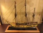
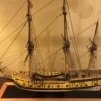
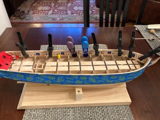
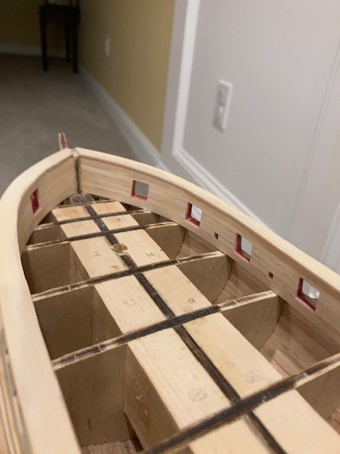
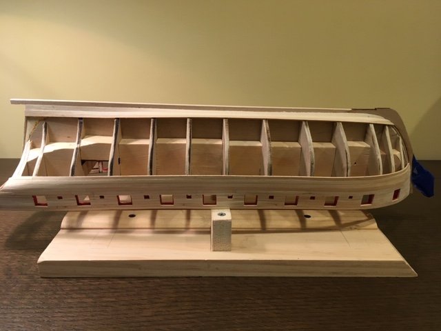
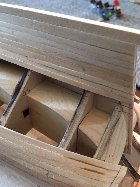
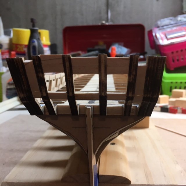
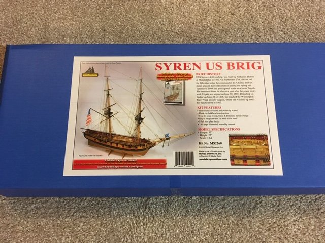
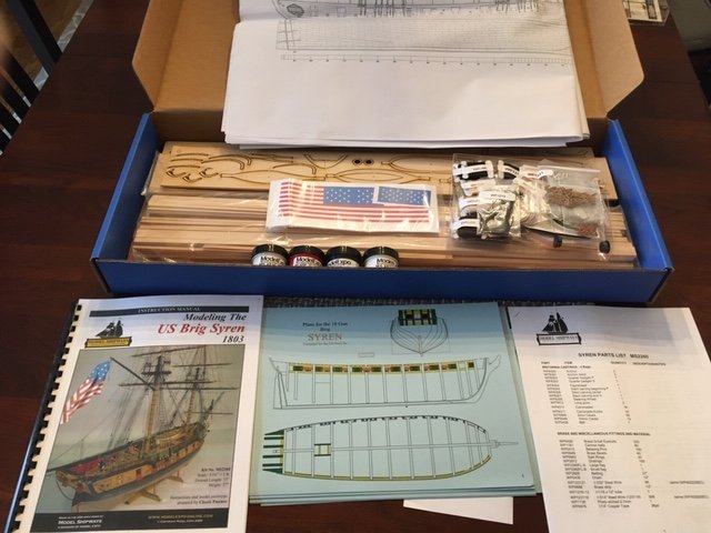
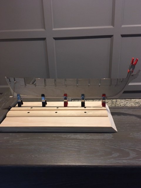
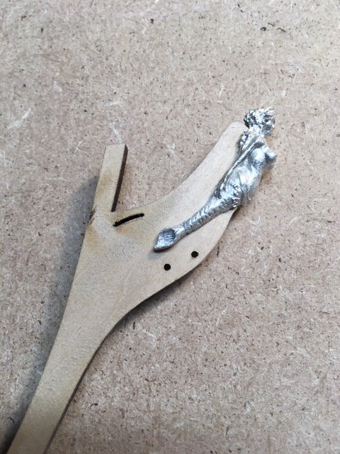
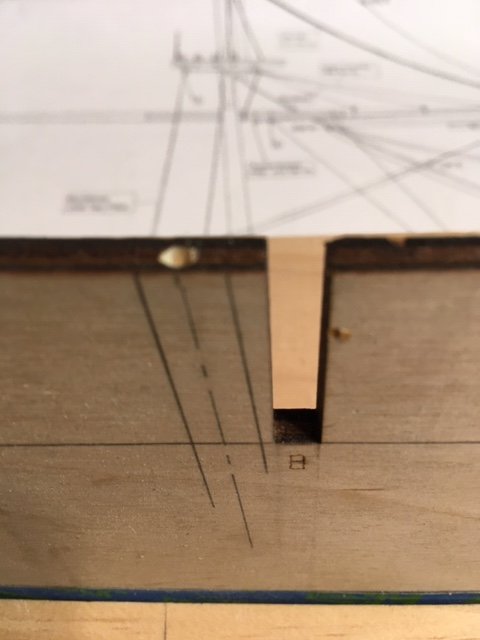
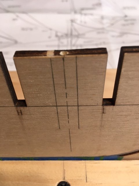
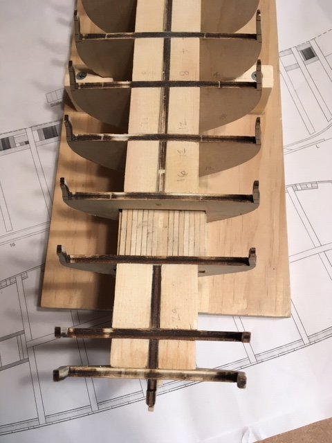
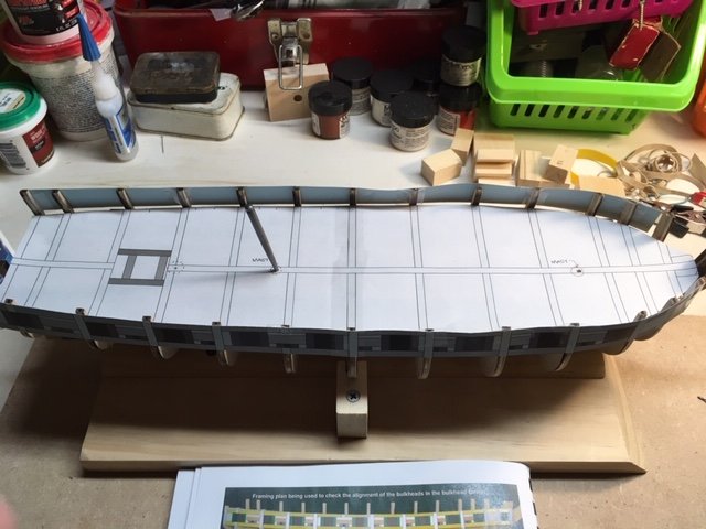
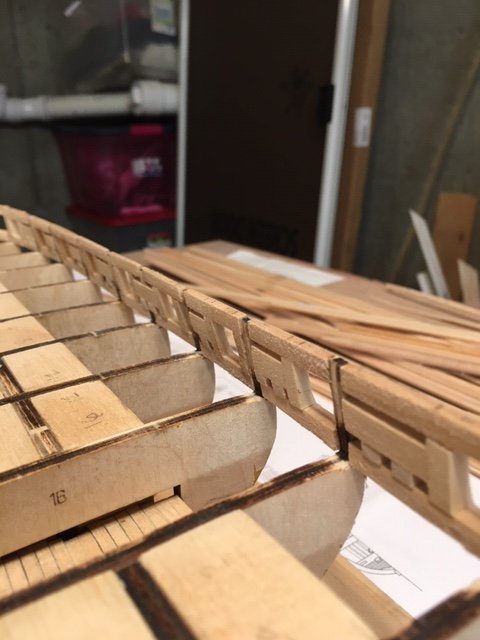
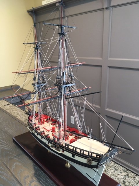
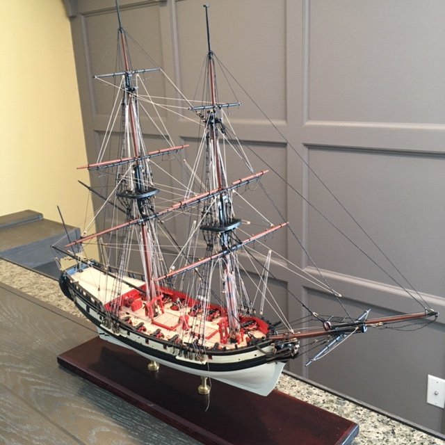
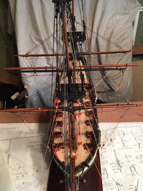
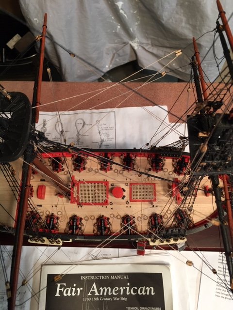
I recently completed the Fair American, which is my second build. It followed my first build– a solid hull Model Shipways Rattlesnake-that I completed 45 years ago. Looking back on the years, I had no prior ship model experience prior to the Rattlesnake. I had seen some ship models in a hobby shop, and I decided to try my hand at the Rattlesnake. IMO, the build turned out good. The 45-year hiatus was due to raising a family and making a career in civil engineering. Then, came retirement and an opportunity to try my hand at ship building again. I’m glad that I did. The experience was so gratifying that I decided to embark on a third build – the US Brig Syren. I ordered the ship from ModelExpo shortly before it temporarily closed its operations due to the Coronavirus outbreak. While awaiting delivery, I studied Chuck Passaro’s fine instructions on-line at the ModelExpo website. As I progressed through the instructions, I compared them to some Syren build logs on the Nautical Research Guild site – it helps to read other build logs and to learn from their experiences. From what I have read, I suspect this build is going to be very challenging. It’s going to test my resolve. Anyway, this is the first post on my Syren build. It starts with the obligatory photo of the ship model box. I checked the parts list against the contents and found everything to be in order. I labeled the size of the various bundled wood strips for quick reference. The numbered and lettered bulkheads (BH) were tested in their proper slots in the bulkhead former (BF). They fit nicely – no sanding necessary. The BHs will be beveled later. I soaked the 3/32” x 1/16” rabbet strip in water for about 20 minutes and then attached it to the BF, held in place with rubber bands and clips as per the instructions. After it dried, I permanently glued it to the BF, taking care to be sure that it is centered. I also glued a rabbet strip to the stern. I let the rabbet dry overnight. While the glue was drying on the rabbet, I began beveling the BHs, both outboard (first) and inboard (second). I decided to complete all the beveling before returning to the rabbet. Returning to the rabbet, I traced the laser cut bearding line and perforated holes to establish the bearding line and then carved the taper from the bearding line towards the rabbet edge. I tapered the bearding line toward the keel with a chisel and sandpaper. I completed one side when I discovered that I used the wrong size rabbet strip – Duh. So, I removed it. I decided to taper the bearding line on the opposite side of the BF before replacing the rabbet with the correct size strip. This worked out well, and it made me wonder why the tapering of the bearding line couldn’t be done before fitting the rabbet strip. For me, it was easier. You just need to taper each side evenly so as to leave a wide even plane on the bottom of the BF to glue the rabbet strip. With the taper from the bearding line to the rabbet complete, I repeated the process of installing the rabbet. I let the rabbet strip dry overnight. I turned my attention to the stem knee. I tapered the stem knee to fit the figurehead. I filed the figure to lessen the amount of taper and for her fit better. I took care not to taper the stem knee beyond the bob stay holes. I laid the BF, the stem knee, and the 3/16” x 3/16” basswood strip for the keel flat on the work bench and checked that the rabbet depth was about the same on both sides of the stem and the keel strip. I had to sand the rabbet one side to deepen the depth of the rabbet. The keel strip was fine. I glued the stem knee, secured it with clamps, and let it dry sufficiently before gluing the keel strip. While waiting for the glue to dry, I tapered the two laser cut bow fillers. I attached the false keel with blue masking tape to protect the keel. At this point, I decided to drill some pilot holes (1/8") in the BF for the masts as some other builders had done. I superimposed the BF onto the plan sheet and marked the angle of the masts on the BF using a straight edge aligned with the center line of the masts. Inserted the BHs into their respective slots, making sure that the scribed sides of each lettered BH face towards the bow and that all sides of each numbered BH face the stern. I faired the BF as per the instructions, checking the fair with a 1/8” x 1/16” planking strip. Rather than glue all the BHs permanently and then cut and glue the filler blocks, I glued each BH and cut and glued the filler blocks as I went along. I started with BHs P, N, and L, jumped to BH 26 and 24, and then completed the process from BH D through BH24. The filler blocks were cut from 1” x 2” pine stock left over from a home improvements project. With BHs and filler blocks in-place permanently, I did more fairing, outboard and inboard. Cut 1/16” x 1/8” basswood strips for the platform between BHs 16 and 20. Ran a pencil across the edge of each plank to simulate the caulking between them, and each one in-place. Opted not to add tree nails since they won’t be visible. The planks will be cleaned up and stained with MinWax Golden Oak later. Moving on to Chapter 3, I taped the framing template to the bulkheads. As can be seen in the photos, the BHs align closely with the template, except for the bow. This did not surprise me because I had read in other build logs that the templates are way off – they don’t align with BHs P and N. To check the squaring of the BHs, I cut out the overhead view template and placed it on the deck. The BHs align closely with the overhead view template. Also, as a check on my mast pilot holes, I superimposed the overhead view template on the plan sheet an marked the locations of the masts – the pilot holes are spot on. As I interpret the template, the bottom of the template represents the bottom of the 3/16” wide gun port frame. The top of the bottom yellow line would be the gun port sill. I pinned a batten at the bottom of the template on the starboard and port side of the hull. I removed the template to find that the batten doesn’t completely align with the bottom reference line etched onto each bulkhead. Considering that they aren’t that far off, and that the instructions say the bulkheads may not be sitting in their respective slots at precisely the same level, I decided to use the batten as a guide. I marked each bulkhead edge with a pencil along the top of the batten and removed the batten. The batten also serves to check the fairing. The fairing looks good as the run is fairly (no pun intended) smooth with no humps or dips. Based on the plans, the gun port sills are 3/16” above the top of the BHs (1/16” for the plank. 1/16” for the waterway, and 1/16” for the swivel bracket). So, rather than use the batten, I opted to use a 3/16” strip as a guide in locating the gun port sills. I placed the 3/16” strip on the top of the BH as a guide to align the top of the gun port frames. I think this approach should pretty much assure that the gun ports will be probably aligned with the carronades – time will tell. While waiting for Amazon to ship my Dremel 8220 cordless rotary tool, I started measuring, cutting, and fitting the gun port sill frames from the ¼” x 3/16” wood strips. I used a mini miter box for cutting the strips. Starting on the port side, I glued the frames in place (from stern and bow), taking care that the top (sill) of the frame was set flush with the 3/16” guide strip. While the glue was drying, I cut and fit the starboard side gun port frames. The ¼” wide strips require a lot of sanding – I had planned to use the Dremel. To alleviate the amount of inboard sanding, I set the frames such that they protrude just beyond the BH. The consequence of this is that it increases the amount of outboard sanding. To lessen the outboard sanding, I trimmed the frames before sanding. I sanded and filed the port side gun port frames inboard and outboard - wish I had my Dremel. Then, I glued the starboard side gun port frames, allowed the glue to dry, trimmed the frames, and sanded and filed them inboard and outboard. For the placement of the gun port lintels, I used a block cut to 15/32” to position the lintels. The process for installing the gun port lintels is the same as the gun port sills. I set the 15/32” block on each gun port sill and the lintel on top of the block and glued the lintel in-place. Whence the glued dried, I sanded and filed the lintels by hand to fair them with the hull. At this point, some the lintels are a little less than 1/8”, so I want to be careful not to over sand them. Next up, the green frames. I set up the template as per the instructions and I marked the locations for each vertical green frame on the gun port sills and lintels. I measured and cut the frames from 3/16” x ¼” stock. I glued the green frames in place using the 15/32” block as a guide. As with the sill and lintel frames, I trimmed the green frames to lessen the sanding. I sanded the outboard frames to match the BH stanchion profile. Using a 1/8” wood strip as a guide, I placed it on the port sills and marked the position of the red (horizontal) frames. I measured and cut the frames from the 3/16” x 1/14” wood strips. The frames were glued in place with the 1/4” side facing outboard – no trimming required here. I held off on sanding the red frames until after the blue frames are installed. I made a 1/8” x 1/8” block to square the sweep ports. Measured, cut, and glued sweep port frames (blue) in place. I did some final outboard sanding. The hull fairing looks good. Only one glitch so far - While sanding the lintels, BH 4 broke off. I glued it back on but didn’t get it perfectly aligned. As a result, in the last photo you’ll notice the port side of the hull has a hump at BH 4. This may not be noticeable after the bulwarks is planked and the cap rail is installed. I’m satisfied with the progress, however. Next up, Chapter 4 – Stern Framing. Stay tuned.
- 157 replies
-
- 8
-
-
- model shipways
- syren
- (and 1 more)
-
I recently completed the Fair American. I didn’t have any problem with the scale of the drawings. I did find that the plans lack a lot of detail, especially the rigging plan. The instruction manual is also lacking in discussion on some aspects of the build. In spite of that, I’m satisfied with how my build turned out.
- 1 reply
-
- 1
-
-
Thanks for following my log. I hope it will be helpful.
-
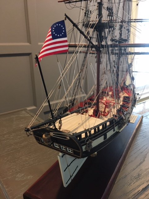
On second glance, after looking at some other builds, I decided the flag was not too large. Using a fine point awl, I punched a small hole through each of the inside corners of the flag, and lashed the flag to one of the falls of the topgallant flag halyard. Lastly, I attached an engraved plaque (purchased from Rossi Engraving on Amazon Marketplace) to the display base. The model is now finished. At some point in time, the ship will be displayed in a case. I'm moving on to the next, more challenging build - The US Brig Syren.
- 61 replies
-
- 5
-
-

-
- fair american
- model shipways
- (and 1 more)
-
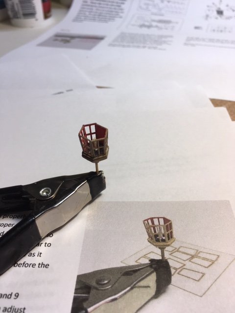
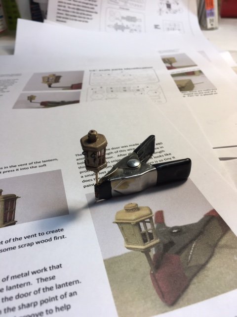
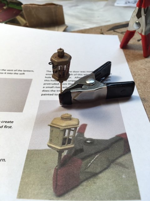
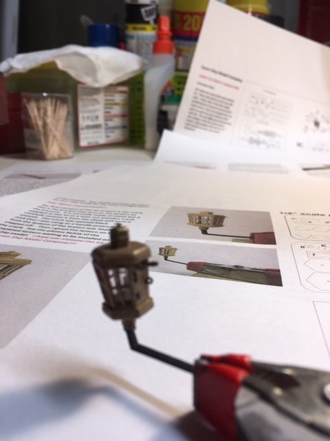
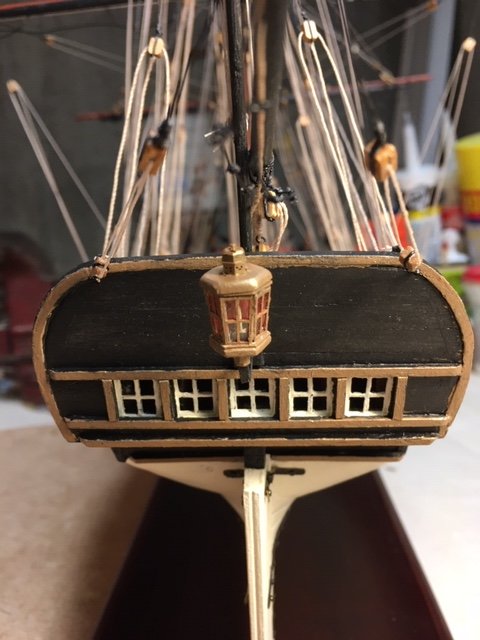
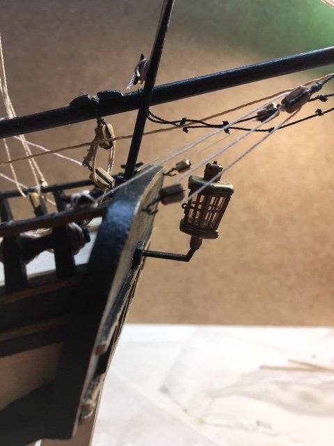
Completed the stern lantern. It was fairly easy to assemble with the Syren instructions. The most difficult part was fitting the pieces on the 1/32” x 1/32” boxwood strip. The strip is larger than the square holes in the pieces, so the stick must be filed quite a bit - not an easy task. In the process of fitting the pieces, the strip broke a couple of times. Fortunately, the strip is long enough to compensate for breakage. Even though the instructions say not to, I found it easier to enlarge the square holes – it didn’t impact the assembly at all. BTY, the 40 mm American flag that I ordered from Flaggen für den Schiffsmodellbauf is too large, so I’ll have to find another supplier.
- 61 replies
-
- 5
-
-
- fair american
- model shipways
- (and 1 more)
-
When have you actually passed the halfwaypoint in building a kit?
abelson replied to Vane's topic in Wood ship model kits
I'm talking in terms of model itself and not the time frame to complete it. As you know, there are many factors that affect the time frame, not withstanding the level of detail you want to achieve. Also, each model is different. -
When have you actually passed the halfwaypoint in building a kit?
abelson replied to Vane's topic in Wood ship model kits
For me, the half way point starts with the rigging. -
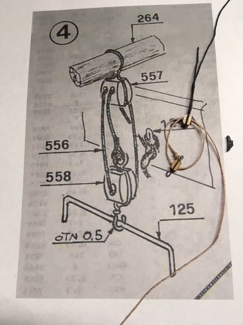
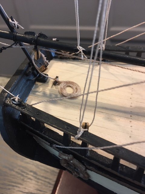
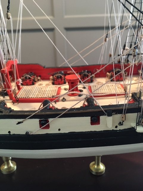
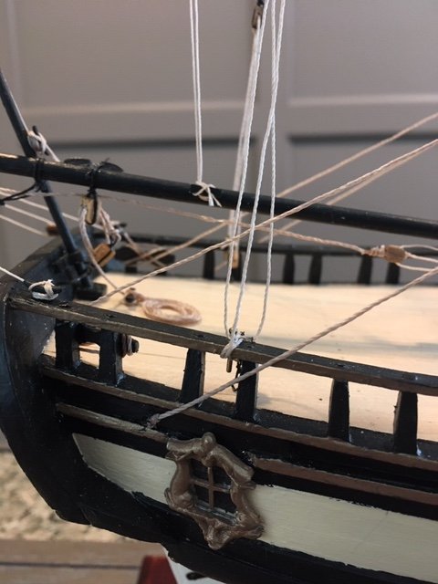
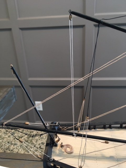
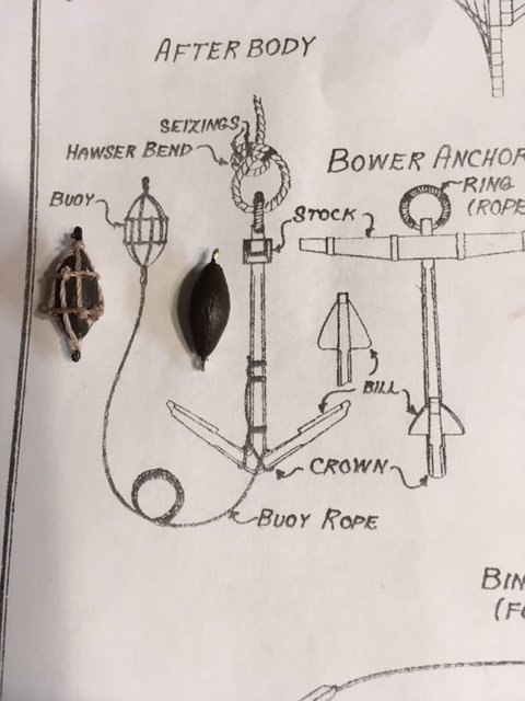
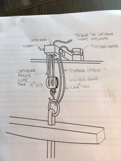
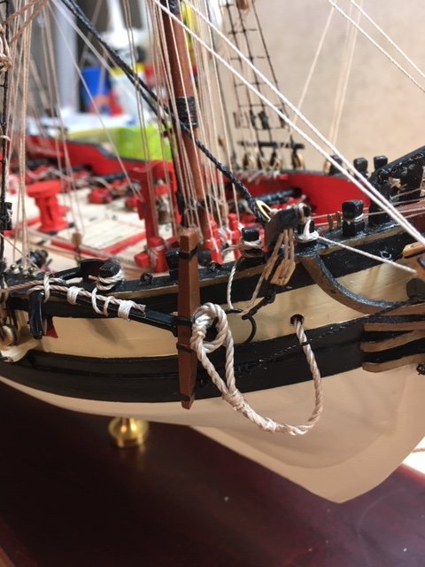
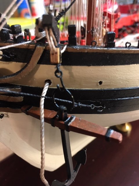
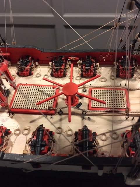
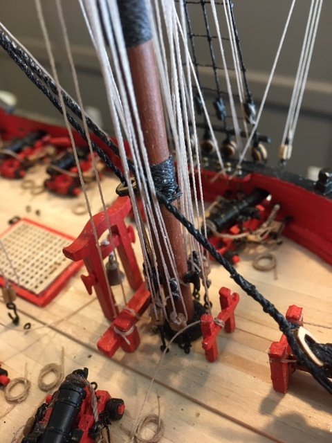
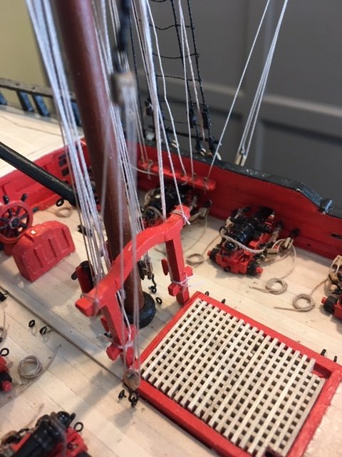
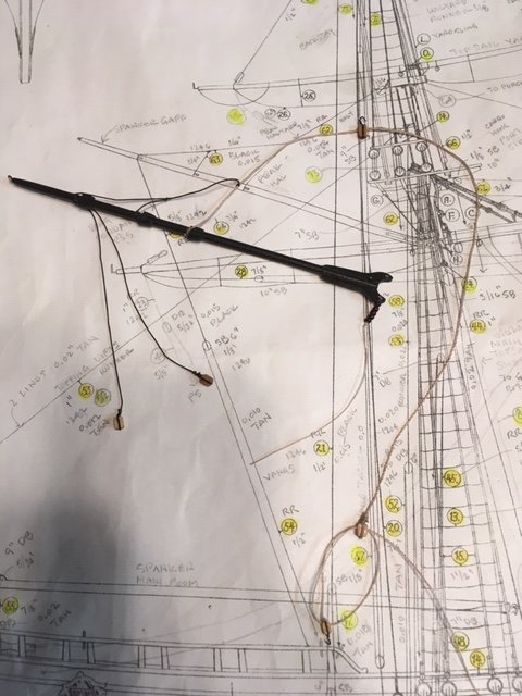
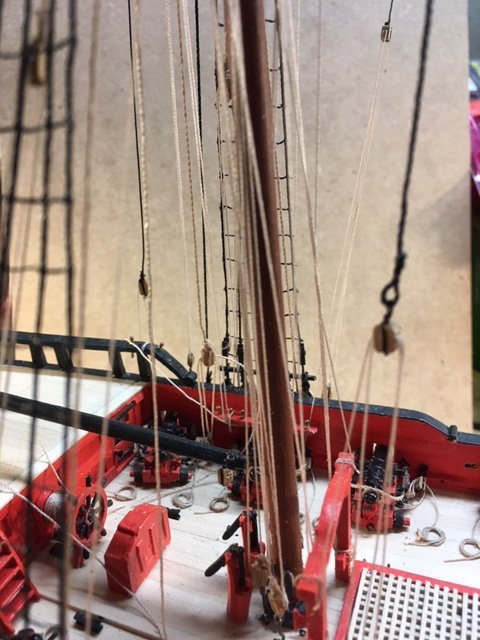
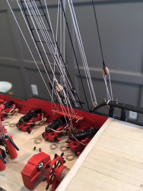
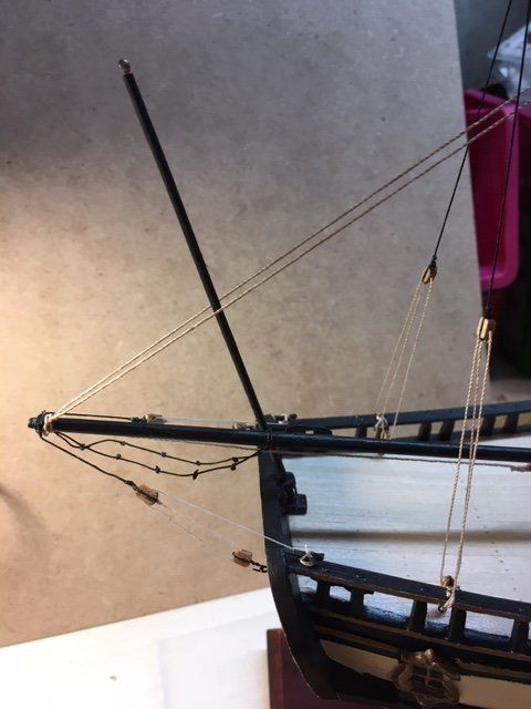
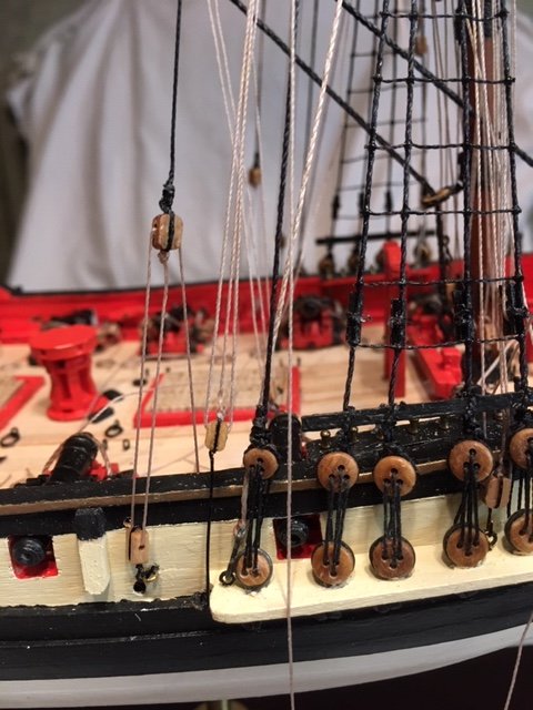
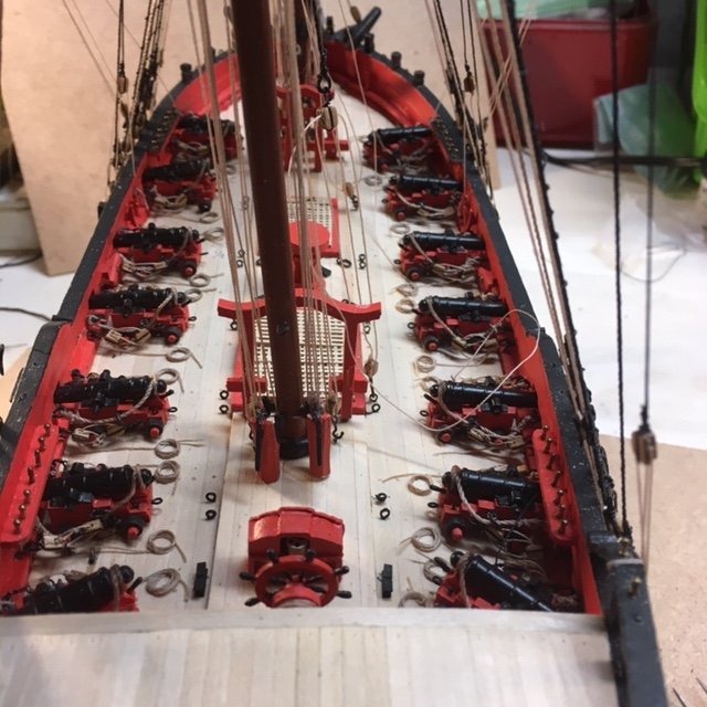
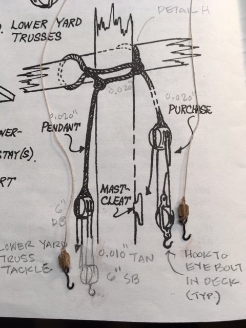
I added the spanker boom sheet (55). The boom sheet consists of 0.020” tan line rove through a 9” double block lashed to the boom and a 9” single block hooked to the traveler horse. The line is belayed to a cleat and coiled on the quarter deck. This is different than the rigging plan, which calls for the line to be belayed to a cleat on a 9” double block. It didn’t make sense to me that a cleat would be attached to a double block. So, I did some research (see drawing) and decided to attach the line a cleat on the deck. At this point, I’m about ten months into the build and the ship is nearing completion. All that remains are the clews, sheets, and tacks, flag halyards, rope coils, and the anchors. Note: there is no discussion in the instruction manual on how to rig the anchors. However, there is a detail on Plan Sheet 1. Refer to FA 16 Gun Brig Fair American-Standing and Running Rigging chart for buoy, hawser, and lashing line sizes. I set up the fore top sail clew assembly (previously fashioned). The clew garnet lines (0.015” tan) are tied to the fore lower yard on each side of the mast and are rove through the 7” block in the clew assembly and then through a 6” single block on the yard arm beneath the top. From there, the clew garnets are belayed to the fore pin rail (P&S) as per the belaying pin plan. The fore sheets (0.020” tan) are rove through the 9” block in the clew assembly. One end goes down through a sheave in the side of the bulwark and is belayed to an inboard cleat (P&S) and the other end is tied to an eye bolt on the bulwark. The fore tacks (0.015” tan) pass through the other 7” block in the clew assembly. One end is spliced to the end of the boomkin, the other end passes through the boomkin block, is tied to the timber head, and belayed to the inboard cleat. The main top sail clew assembly is set up similarly. The clew garnet lines are belayed to the pin rail as per the belaying pin plan. The main sheets are tied to an eye bolt in the aft bulwark and belayed to the cavil. For the main tacks, one end runs through the bulwark chess tree (P&S), then through a hole in the bulwark, and is belayed to an inboard cleat as shown on the belaying pin plan. I couldn’t figure out the tying off point for the other end of the tack, so I eliminated it by making a stopper end in the clew assembly block. I added the fore and main flag halyards (0.012” tan). The flag halyards pass through the sheaves (P&S) in the truck on top of the topgallant mast and are tied off on the sheer pole (P&S). I added the gaff flag halyard (0.012” tan). The gaff flag halyard runs through a 6” single block at the end of the main gaff. The free ends run down to the main boom, where they are tied off to a cleat on the side of the boom. A flag will be hung on the gaff flag halyard. I also added the flag staff halyard (0.012” tan). The flag staff halyard runs through a 6” single block at the end of the staff. The free ends are tied off to a cleat on the side of the staff. Next up, the anchor and anchor buoys. There is no discussion in the FA instruction manual on the anchor and anchor buoys. However, there is a photo on page 41 that depicts the anchor. I used Chuck Passaro’s Syren build as a guide. First, I fashioned the anchor buoys from ¼” x ¼” scrap wood and shaped them to match the detail on the Plan Sheet 1. They are 5/8" long. Before tapering them, I drilled a hole in each end for an eye bolt. I painted them with a mixture of burnt umber and hull black. I made the two rigging harnesses from 0.018” tan line. The rigging harnesses were a bit tricky to make. They're not museum quality, but I’m satisfied with them. I added the tackle (0.02” tan) and a 9” hooked double block on the cathead. The tackle (catfalls) is rove through the block and the cathead sheave. One end is belayed to a cleat on the cathead, the other end is belayed to inboard bulwark cleat (See sketch taken from Passaro’s Syren build). The anchor has a stopper cable (0.06” tan) that goes through a hole on the cathead, through the anchor ring, and is belayed to the timberhead. I made the anchor ring from 20-gauge wire. I cut a length of 0.020” tan line for the buoy line. I lashed the buoy line to the anchor with 0.008” tan line and wrapped it around the bottom of the anchor as shown on the plan. The other end of the buoy line is tied to the eyebolt on the buoy. I cut a short length of 0.020” line and seized it to the other eyebolt on the buoy. This line will be seized to the shroud. Before doing that, I passed the hawser cable (0.060” tan) through the anchor ring and seized it as shown on the plan. Then, I lashed the anchor in position to a timber head. With the anchor secured, I seized the buoy line to the fore most shroud approximately 9 rat lines up from the shear pole. You can use your own judgement here. The excess line was snipped off. I seized the buoy line between the buoy and the anchor to the same shroud. I tied a rope coil (0.020” tan) at the exact location where the lower buoy line is tied. I used a 9/32” socket for the coil. I positioned a short length of 0.008” tan line on the socket, wrapped the line around the socket 7 or 8 times, and tied it off. I added a smaller rope coil (¼” socket) above the buoy at the exact location where upper buoy line was seized to the shroud. I wrapped the line around the socket 5 or 6 times and tied it off. I added capstan bars to the cast capstan similar to the photo on Page 42 of the FA instruction manual. The bars are fashioned from toothpicks (4-foot long at ¼” scale). I reamed the capstan notches in the capstan top to accommodate the toothpicks. The model is complete, except for adding the stern lantern and a period correct American flag. I ordered a stern lantern kit from Syren Ship Model Company. I’m using the 3/16" Scale (1:64) Stern Lantern Kit - 7/8" tall (same as the FA plan). I also ordered a LEECH 40mm "5005 First flag of USA 1777 - 1795, stars and stripes after design by Betsy Ross” from Flaggen für den Schiffsmodellbauf http://www.schiffsmodellflaggen.de/english/Catalog/catalog.html. I will update the log when these items are complete. This build has been very enjoyable for me. It's reinforced my confidence that, 45 years after my first build, I still have the patience and dexterity to build model ships. I hope that this build log will be informative to future Fair American modelers.
- 61 replies
-
- 6
-
-
-
- fair american
- model shipways
- (and 1 more)
-
Did you use 40 mm or 64 mm?
-
I find that Model Expo frequently overcharges for shipping when you order on-line. The flat rate is $9.95 regardless of what you order. I did discuss this with John Garcia and he said he can't check every on-line order. In fairness to John, he has credited my account several times for overcharging on shipping. I find that it is easier to order on-line than it is to call Model Expo - it's very rare that someone answers the call, and John doesn't always get back to you when you leave a voice mail message.
-
Anyone know a site where I can order an america flag for my Fair American build?
-
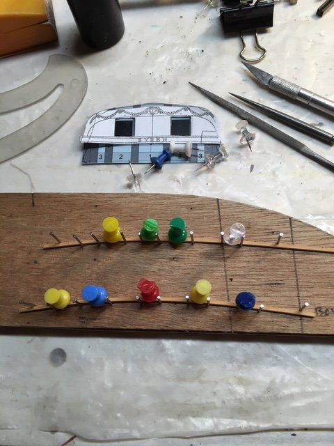
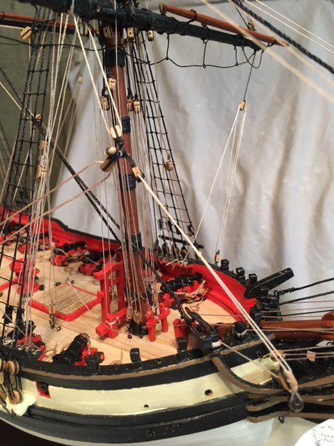
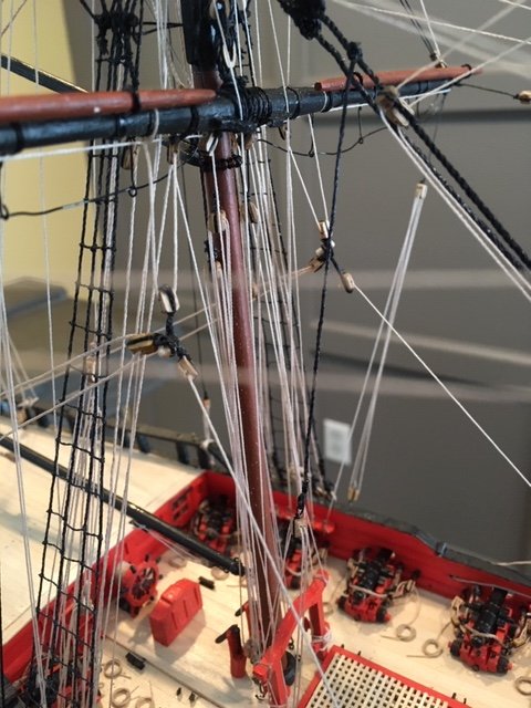
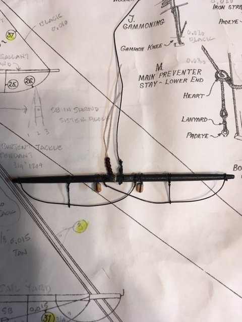
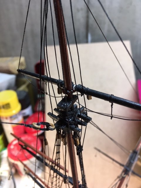
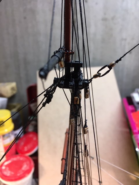
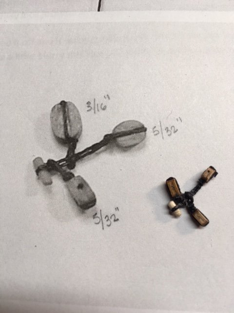
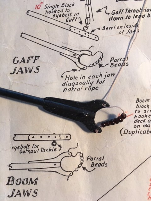
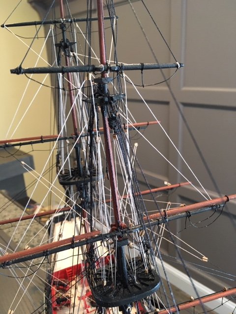
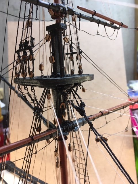
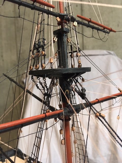
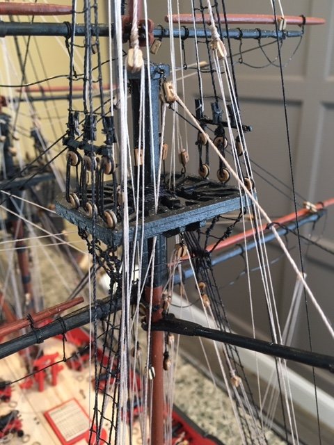
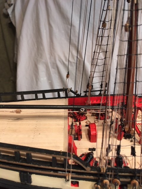
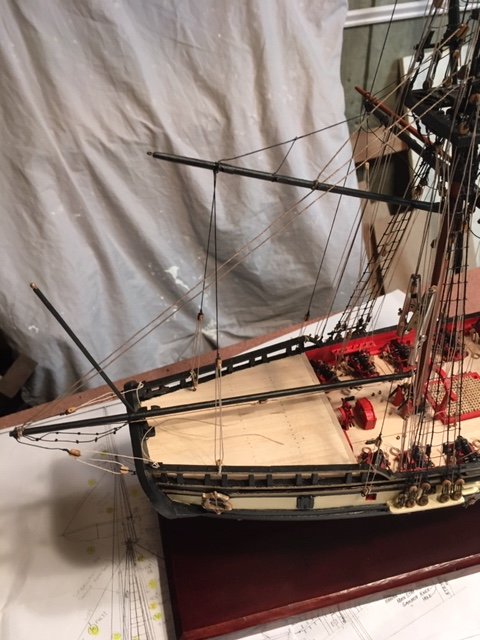
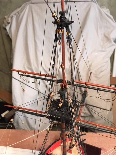
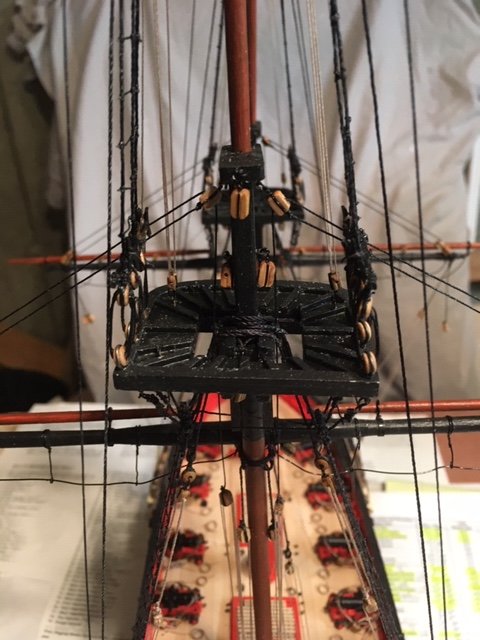
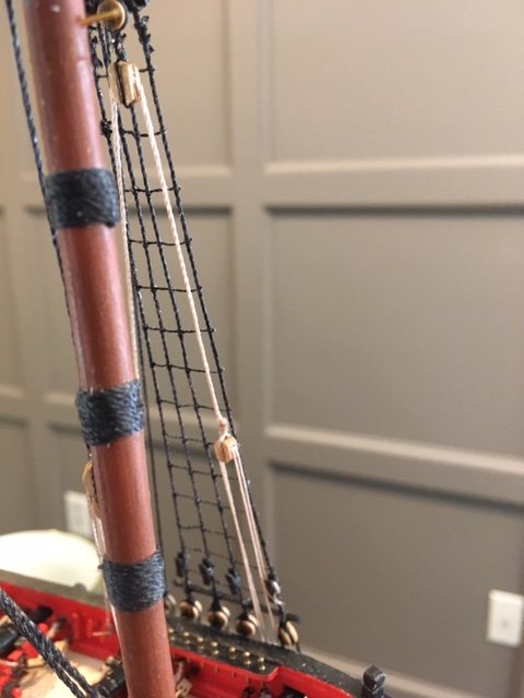
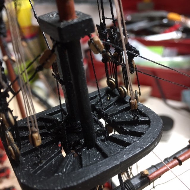
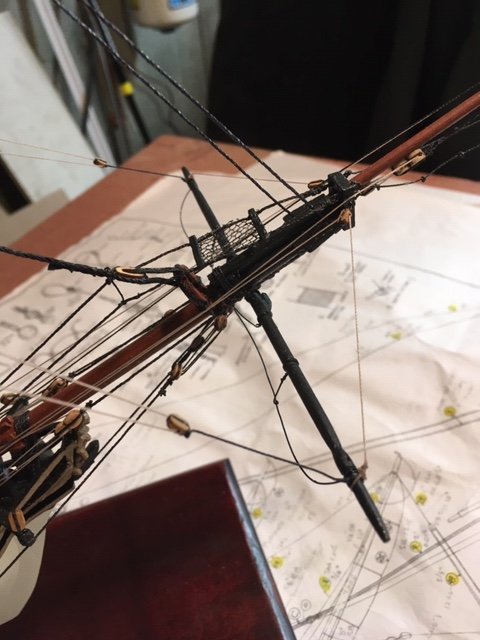
Stepped the main topsail yard and the fore and main topgallant yards. The main top sail yard is set up same as the fore top sail yard. The hauling end of the yard parrel passes down through the Lubber’s Hole and is belayed to the main gallows bitts. The main topsail halyard runner (72) and tackle (57) is set up same as the fore top sail. The halyard tackle pendant is hooked to an eye in the aft end of the aft channel (P&S). The runner is belayed to the aft pin rail (P&S). The main and fore topgallant yards are pinned to the topgallant mast about ¼” above the mast cap. I used some beads left over from my Rattlesnake build. The yard parrels were fashioned similar to Detail R on the rigging plan using 0.012” tan line. I used 6 parrel beads. The topgallant halyard tyes (76 & 77) (0.010” black) were setup with a tackle (70 & 73) (0.010” tan) consisting of a 6” double block and a 6” single block hooked to an eyebolt in the tops over the port side trestletree. The tackle runner is belayed to the port pin rail fore and aft. Completed the fore top sail yard lifts (35). The instruction manual says the lifts are standing lifts with no hauling parts. I opted to make these running lifts a la rafine’s build. I used 0.010” tan line. One end of the lift is rove through a 6” single block tied to the end of the top sail yard, up through a 6” single block lashed between the forward most pair of fore top shrouds above the stave, down through the Lubbers Hole in the fore top, and belayed to the riding bitts. The other end is rove through a 6” single block tied to the fore topgallant yard, down the Lubbers Hole in the fore top, and belayed to the riding bitts. The riding bitts seemed like a logical place to belay the lifts. The main top sail yard lifts were rigged same as the fore top sail yard lifts except the ends are belayed to the main gallows bit cleat. I completed all of the braces (0.010” tan). It’s a little tricky to align the yards squarely. The tension on each brace must be adjusted to square the yards to align. It’s a adjust one, adjust the other situation until the alignment is right. The braces are as detailed on rigging plan, and the landing points of hauling ends are as indicated on the belaying plan. As more lines are lashed to the pin rails, I found it more difficult to lash the lines. My lashing is by no means museum quality work. I ran out of 0.012” tan line, so, while waiting for a Model Shipways order, I decide to work on the block assembly for the clew lines, sheets and tacks. I copied the block assembly from Chuck Passaro’s Syren build. [Note: These lines are not shown on the plans. The instruction manual refers to Steel and Lever for rigging clew lines. These are authors of books referenced in the FA instruction manual bibliography. The books are available for purchase on-line. I opted to use my Rattlesnake rigging plan as a guide, as well as other FA build logs.] The assembly has three blocks, two 5/32" (7”) single blocks and one 3/16" (9”) single block. The 3/16” block has a toggle stropped to it. The other two blocks have eyes stropped to them and are slipped onto the toggle just before the final block is added to it. I fashioned the toggle from a toothpick. I used 0.021” black line for the 5/32” and 0.020” black for the toggle strop. The block assemblies are not quite up to Chuck’s standard, but I like them nonetheless (see photo). Next up, the main gaff. I added 8 parrel beads to the gaff jaw as detailed on the Rattlesnake rigging plan (see photo). The gaff peak halyard bridles (63) (0.015” black) and peak halyard (62) (0.20” tan) were added next. The bridles and peak halyard are tied to each other. Before rigging the peak halyard, the gaff is attached to the main mast in its raised position. The parrel is looped around the mast and tied off to the parrel strap eye in the gaff jaws. With the gaff secured, I passed the peak halyard through a 9” single block hooked to an eyebolt in main top mast cap. The peak halyard is set up with a tackle (0.012” tan) consisting of a 7” double block and 7” single block hooked to a deck eyebolt in the port side of the ship. The peak halyard tackle is belayed to the port pin rail. The gaff throat halyard (58) (0.020” tan) consists of and a 9” single block hooked to an eyebolt in the aft cross tree and a 9” block hooked to the throat halyard eye. Note: The gaff throat halyard is not shown on the FA rigging plan. The gaff throat halyard tackle consists of a 6” double block and a 6” single block hooked to a deck eyebolt on the starboard side of the ship. The peak halyard throat tackle is belayed to the starboard pin rail. Lastly, I made up the paired vangs which consist of pendants (29) and tackles (54). The pendants (0.015” black) and tackles (0.010” tan) are set up with a 6” single pendent block and a 6” single block hooked to an eyebolt in the quarter deck and belayed to a pin in quarter deck rail. The spanker boom is next. I added foot ropes (0.012” black), guy pendants and tackles, and the spanker boom outhaul. These are not shown on the rigging plan nor discussed in the instruction manual. However, the 16 Gun Brig Fair American-Standing and Running Rigging chart does include them. Referring to that chart, I used 0.015” black line for the foot ropes. I tied knots on the ropes at 2-foot intervals. For the guy pendant, I used 0.012” black line. The guy tackle consists of a 6” single pendant block and a 6” double block hooked to an eyebolt on the transom, and 0.012” tan line rove through the blocks and belayed to a cleat on the quarter deck rail. The spanker boom outhaul (0.020” tan) with stopper knot passes through the sheave in the aft end of spanker boom to a tackle (0.010” tan) consisting of a 6” single block and a double 6” block hooked to an eyebolt under the boom and belayed to a boom cleat. The spanker boom has a hook (goose neck) in its fore end that is attached to an eyebolt in the main mast, as per the FA rigging plan. I had to order more 7” single blocks and 9” double blocks to complete the boom lift tackles and sheet. This made me think of all the previous block orders I’ve had to make because the FA kit doesn’t provide enough blocks. The kit comes with 55 blocks of various sizes. The number of blocks required to rig the ship as per the 16 Gun Brig Fair American-Standing and Running Rigging chart is approximately 250, if my count is correct – I didn’t double check it. This includes 56 blocks to rig the cannons. The FA instruction manual does say that materials to rig the guns are not included in the kit. Even so, it seems that the number of blocks furnished with the kit is well short of the number required to rig the ship per the 16 Gun Brig Fair American-Standing and Running Rigging chart, if you choose to do so. Each spanker boom topping lift (0.020” tan) is tied to the aft end of the boom and runs up to a single 9” block hooked to an eyebolt in the top mast below the cap and down to a lift tackle (52). The lift tackles are made up of 7” double block and a 7” single block hooked to an eyebolt in the deck (P&S). The tackle runner (0.015” tan) is rove through the blocks and belayed to the pin rail as per belaying pin plan. Note: The rigging plan seems to show the lift tackle being hooked to the aft channel rail, as evidenced by the solid lines. This does not agree with the belaying pin plan. By comparison, the gaff throat halyard tackle (48) is shown (not clearly) as a dashed line on the rigging plan (meaning it’s behind the bulwark as viewed on the plan) and attached to a deck eyebolt (see sketch for clarity). Next up. The clew assembly.


.JPG.6e8a56e996ebbace0119a79411074c75.JPG)
- 61 replies
-
- 5
-
-
- fair american
- model shipways
- (and 1 more)
-
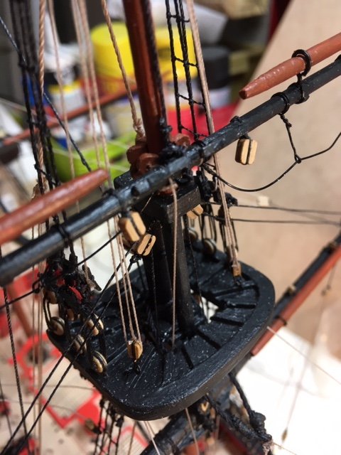
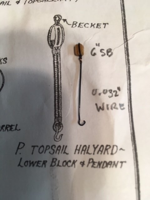
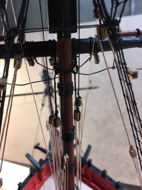
Stepped the main lower yard. Basically, it was the same as the fore lower yard, but a little easier because the work space under the top is not as confined as the fore lower yard. I was able to do a lot of the work from the aft. I set up the main lower yard tackles (49) same as the fore lower yard. The tackle runner is belayed to the main pin rail. I forgot the main lower yard brace pendants (28) so I added them. This would have been easier with the yard not aloft – yet another reason to study the rigging plan closely. Set up the main braces (59) (0.015” tan). One end is tied-off to the aft fore lower shroud below the futtock stave and is rove through the 6” single brace pendant block, the 9” single block tied to the aft fore lower shroud and is belayed to the pin rail (P&S). I set up the fore lower yard braces (61) (0.015” tan). One end is tied to the main stay above the mouse and is rove through the 6” single fore brace pendant, through the 6” single block beneath the main top and will be belayed to the aft pin rail (P&S). Note, Page 36 of the instruction manual says the braces are the last items of rigging. I decided to add them as the rigging went along. However, I didn’t belay the braces in case they interfere with other rigging. I set up the main lower yard topping lifts (64) same as the fore lower yard lifts. Next, I stepped the fore top sail yard. The yard is pinned to the fore top mast about ¼” above the lower mast cap. I made the yard sling (0.020” black) as per Detail L on the rigging plan. The halyard tye passes through the halyard sheave in the fore top mast and is set up with a 7” single block. The hauling end of the yard parrels passes through the Lubber’s Hole down to the fore bitts where it is belayed. The fore topsail halyard runner (0.015” tan) is set up with two (2) 6” double blocks. The halyard tackle (0.010” tan) is set up with a 6” lower Becket block and pendent (Detail P). I made the lower block pendant using 0.032” wire similar to rafine’s, KenW’s, and EdatWycliffe’s builds. The pendent is hooked to an eye in the aft end of the fore channel (P&S). The tackle is tied to the Becket block and rove up through the double block, down to the Becket block, and up to the double block. The runner is belayed to the pin rail (P&S). The fore top sail braces (60) were set up next. Each brace (0.010” tan) is tied to the main stay above the mouse and is rove through the 7” single block brace pendant (39), and through two 7” lead blocks tied to the main stay as shown on the rigging plan. The braces are belayed to a bulwark cleat (P&S) as shown on the belaying pin plan. Next up, the main topsail yard.

- 61 replies
-
- 5
-
-
- fair american
- model shipways
- (and 1 more)
-
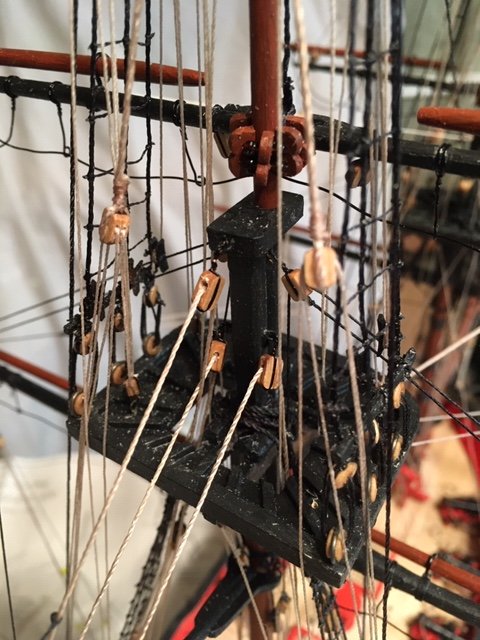
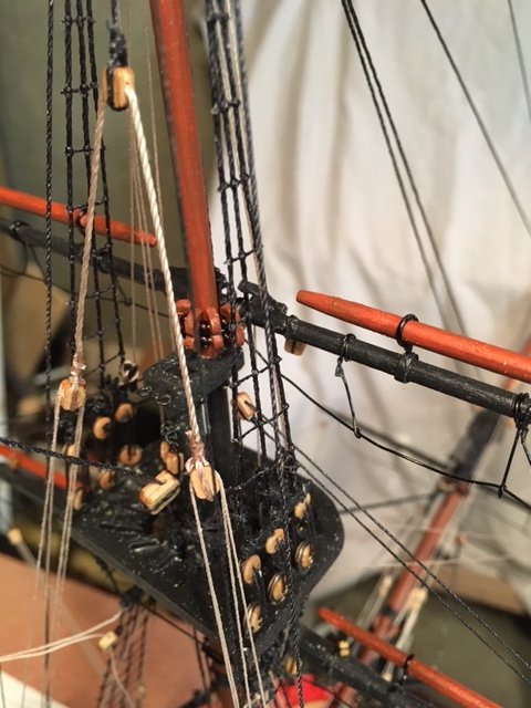
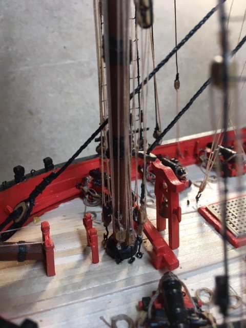
Set up the main and fore mast lower Burton tackles, both port and starboard. From what I have read, the Burton tackles worked in conjunction with the Burton pendants to sway the lower masts in preparation for rigging the shrouds and stays. They would steady the mast and hold the proper position/rake as the shrouds were set up. Afterwards, the pendants were utilized to tighten the shrouds. They were also used for loading and unloading cargo as discussed in the instruction manual. On some ships, the Burton pendants were set up all the time, on others they were unrigged when not in use. The tackle consists of a 9” single block hooked to the Burton pendant eye thimble, and a runner (0.020” tan) that is hooked to an eye in the channel on one end and to a 7" double block on the other end. The tackle runner (0.015" tan) is connected to a 7” single block hooked to the channel, as shown on the rigging plan, and rove through the double block. From what I have seen from Burton tackle details on the internet, the block hooked to the channel would be used for loading and unloading cargo, so why is it hooked to the channel? It seems to me that it would better served if it were hooked to an eye on the deck - just wondering. Neither the instruction manual nor the belaying pin plan indicate where the runner is belayed. I belayed it to a shroud cleat. As a matter of note, I use the block sizes indicated in the 16 Gun Brig Fair American – Standing and Running Rigging chart that I referenced earlier in this build log. The main and fore upper Burton tackles were set up with a 6” double block hooked to the Burton tackle eye and a 6” single block hooked to an eyebolt in the main and fore top. The tackle runner (0.010” tan) was tied to the single block strap and rove off and belayed to a shroud cleat P&S. The main stay tackle (item 51) and the fore stay tackle (50) were set up next. The main stay tackle consists of a 7” double block hooked to the main stay tackle pendent (22) eye, a 7” single block with a cargo hook hooked to an eyebolt in the deck, and a tackle runner (0.015” tan). The tackle runner is seized to the 7” single block and rove as shown on the rigging plan. The fore stay tackle is set up similarly except the 7” double block is seized to the main stay (11). The belaying plan doesn’t show where the runners are belayed. I will belay them to the main and fore gallows later. I set up the sprit sail lifts (40). The lifts consist of 0.012” tan line seized to the end of the sprit sail yard, rove through a 6” single block hooked to an eyebolt in the bowsprit cap. I belayed to the lifts to the knight head because it was easier than belaying them to the pin rail. Next, the sprit sail yard braces (41) were set up. The braces (0.010” tan) are tied to the fore stay below the mouse and are rove through the 6” single block on the sprit sail brace pendant and then through a 6” single block under the fore stay top and belayed to a cleat on the fore mast. I left the braces loose so that they would not interfere with the setting up the yard arm. Note: the 16 Gun Brig Fair American – Standing and Running Rigging chart indicates that the braces are set up with two single blocks under the fore top. The rigging plan also shows two blocks under the top. I had difficulty reeving the brace through the second (aft) block, so I decided to use fore block only, as was done on some other build logs. The fore lower yard was set up with the pin in the fore mast. The yard sling heart and the mast bridle heart were lashed together with a lanyard (0.015” black). The lower yard truss pendants (Fig. 39) were rove through the pendent eyes. A 6” double block was seized to each pendant. Seizing the blocks was difficult due to the confined working space at the underside of the top. The pendants were set up with purchases with a 6” single Becket block hooked to the deck. The truss tackle (0.010” tan) was belayed to a fore mast cleat. I set up the lower yard topping lifts (64) with 6” single blocks instead of crossing them over the mast cap as illustrated in Fig. 40. I decided to do this after reading discussions about this in other build logs. The blocks are hooked to eye bolts under the cap. The lifts (0.015” black per 16 Gun Brig Fair American – Standing and Running Rigging chart) are rove through a 6” single block on the yard and back through the 6” block at the cap and are set up with a purchase same as the truss pendants. The purchase blocks are roughly midway between the deck and lower mast cap. I found these blocks not to be as difficult to seize as the truss pendant blocks. I was able to seize the blocks to the lift above the fore top and then lower the lift and block through the Lubber’s Hole in the top. To trim the yard level, I clamped two small clamps on each end of the yard and then belayed the tackles runners to the mast cleats. The lower yard tackles (49) were added next. The tackle (0.010” tan) is tied a 6” single Becket block hooked to an eyebolt in the fore channel as shown on the rigging plan and rove through the 6” double block on the fore lower yard tackle pendant (23). The tackle runner is belayed to the fore pin rail. Next up, the main lower yard.
- 61 replies
-
- 5
-
-
- fair american
- model shipways
- (and 1 more)