


dunnock
-
Posts
531 -
Joined
-
Last visited
Content Type
Profiles
Forums
Gallery
Events
Everything posted by dunnock
-
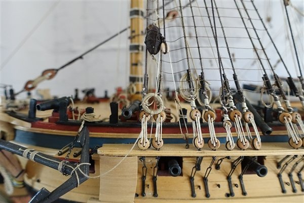
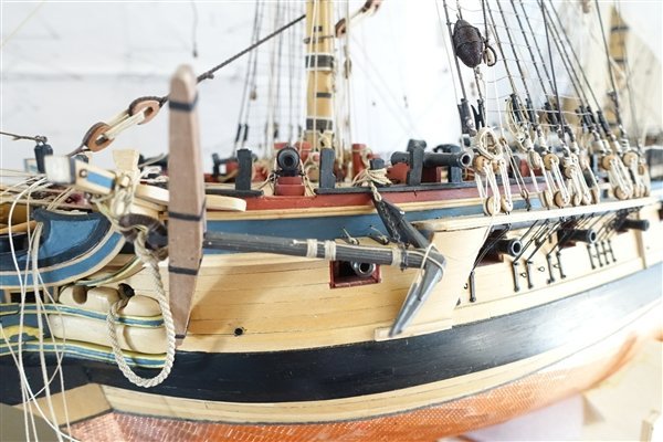
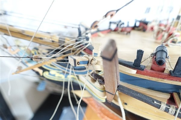
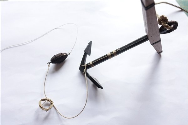
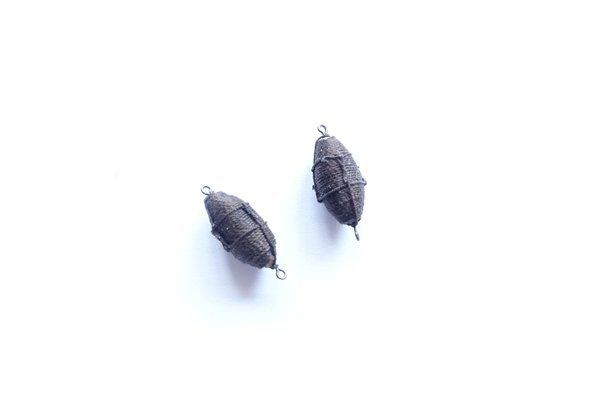
Thanks to all for the likes and encouragement. I made up the four bower anchors a while ago but now seems the right time to add them to the model. I thought that I would have a go at making the anchor bouys for the to add a bit more detail to Diana. I used 8mm limewood dowel as the basis for the bouys and roughly carved them with a scalpel and then finished with sandpaper. Lavery shows four rope slings coming from top and bottom of the bouy with an eyelet seized to take the lanyard and anchor rope. I decided on a simplified route and fitted eyebolts in each end. The form is served with Gutterman polyester thread which is about 0.3mm. I found it easier to wrap the thread from each end towards the middle. Another simplification I made is to add only two slings from each end, both for the sake of sanity and because four slings looked overcrowded to my eyes on this small bouy. The slings are threaded around the hoop and fixed with a false splice. The lanyard 0.25mm, is tied to one end and the anchor rope 0.45mm is spliced to the other. The anchor rope tied around the anchor flukes and then held to the shaft with three seizings. The excess rope is coiled and held with four ties around its circumference. The anchor is tied to the model with the cathead stopper. A 6mm rope with a stopper knot in one end and threaded through the anchor ring. I wasn’t entirely sure of the arrangement of the stopper but I have placed the knot in the cleat on the aft side of the cathead and passed the other end through the ring and tied it off around the cathead. The shaft is held close to the fluke by a length of chain fixed to an eyebolt in the end of the forward channel. A length of 0.6mm rope is spliced to the other end. The chain wraps around the shaft and the rope is tied off to the timberhead. The coil of anchor rope and bouy are tied to the shrouds. The port (best bower?) is completed with the anchor cable threaded and fixed through the hawse hole. Moving on to the starboard… Thanks all for looking in David
- 310 replies
-
- 8
-

-
- Diana
- Caldercraft
- (and 1 more)
-
Amazing work Jason and a great to see your thoughts behind the process David
-
Thanks Andrew but I'm just borrowing the ideas of Blue Ensign Dave - no problem and thanks for your compliments. No air brushing just ordinary artist's paint brushes. I tend to dilute the first couple of coats and light sand in between and then just build up the layers until I'm happy. The blue is Tamiya Medium Blue XF18. The colour is nice but the solvent based acrylics are very fast drying. I've not tried but it may be an improvement to add Tamiya Retarder to slow the drying down. David
- 310 replies
-
- 3
-
-
- Diana
- Caldercraft
- (and 1 more)
-
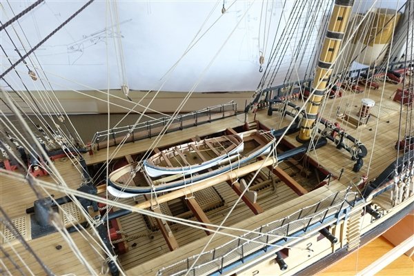
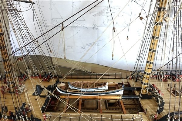
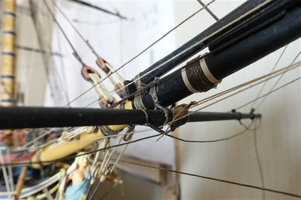
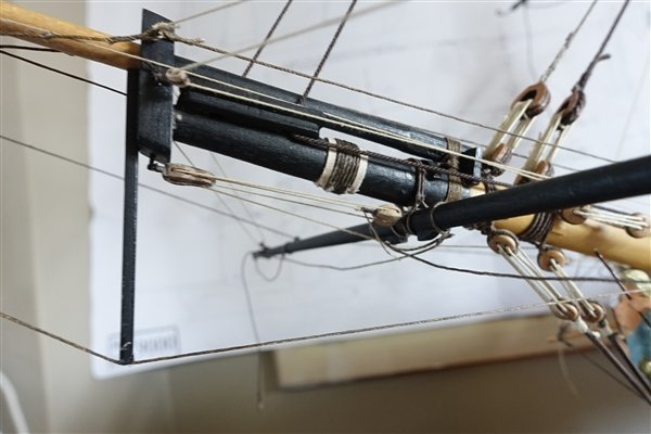
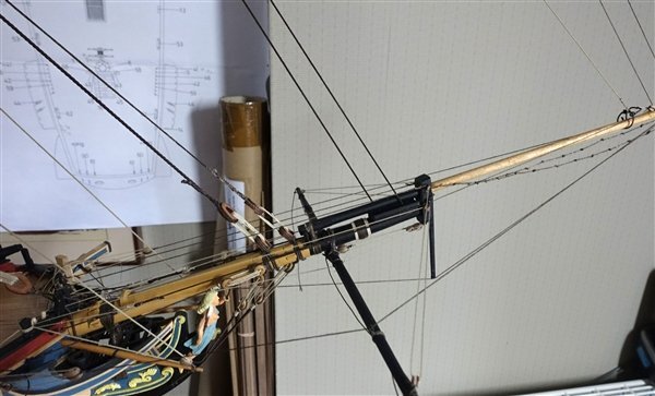
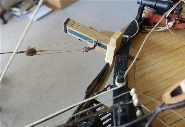
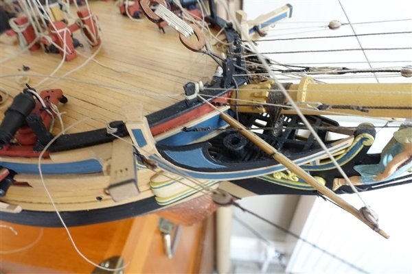
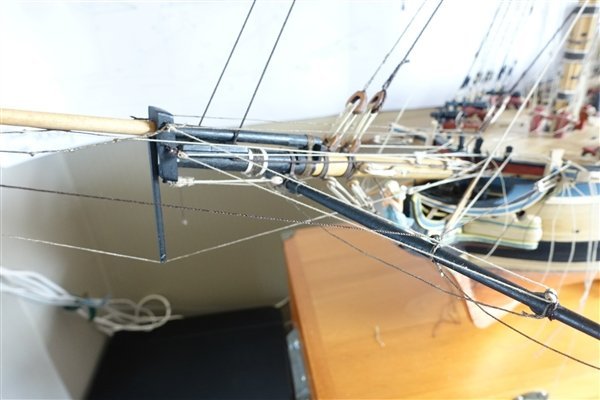
Thanks for the likes. Appreciated as always. Rather than move the eyebolt which would leave a hole to be filled that might be obvious, I added another on the forward side of the gun port to accommodate the main sheet standing part. Sheets and tacks now completed. The pinnace has been tidied up and is lashed to the spare topmasts in the waist. I have also nested the 18’ cutter inside the pinnace. I am still undecided on how to mount or display the launch and 24’ cutter but I have glued the boat cradles in place. The stay tackles have been added. Getting them to hang realistically took some time and I eventually followed BE's lead on Pegasus and propped up the stay with scrap dowel before applying dilute pva to the rope and weighting with clips. On to the spritsail yard. The sling was made according to the second option in Lees; putting an eye in one end and threading the other end through and seizing it to itself. I used 5mm Amati rope served with Gutterman thread. I had missed adding the eyelets for the jibboom guys and the yard lifts off model so now added them. As with the other yards, I replaced the brace pendants with a longer version of 8mm. The spritsail yard halliard consists of a 5mm long block and a 5mm single block. The fall runs to the starboard side of the pin rack at the bow. It’s a bit tricky tying off here with little room to manoeuvre. I used 0.45 RoS rope for the jibboom guys. They have a 5mm block seized to the end. The falls thread througn this block, through another seized to an eyebolt on the forward side of the cathead and tied off at the timberhead. Spritsail lifts are rigged with the standing end seized to an eyebolt at the bowsprit cap. The running end passes through the block on the yard, through another block seized to the lower eyebolt in the cap and leads back to the bow pin rack. I’m left with only the braces to complete the rigging of the yards before moving on to the gaff and driver boom. Thanks for looking in David
- 310 replies
-
- 9
-
-

-
- Diana
- Caldercraft
- (and 1 more)
-
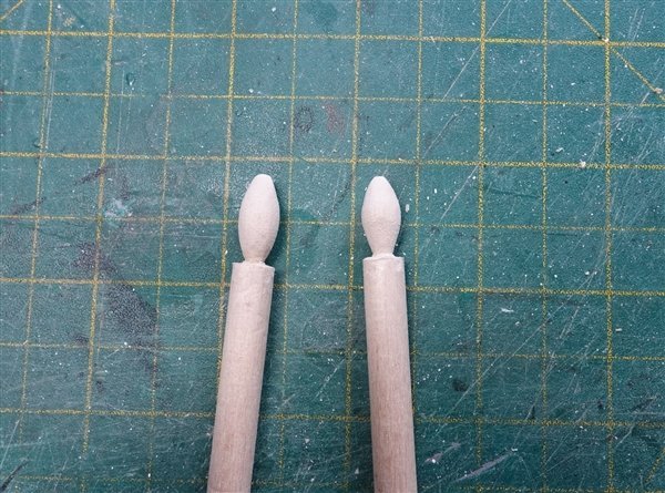
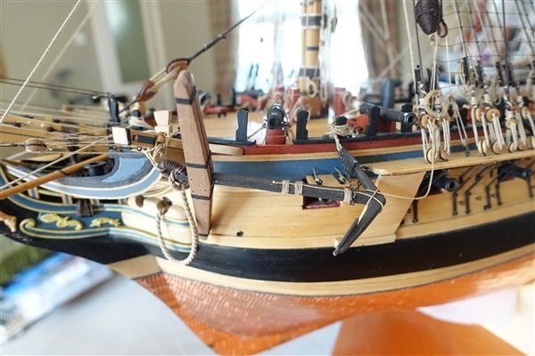
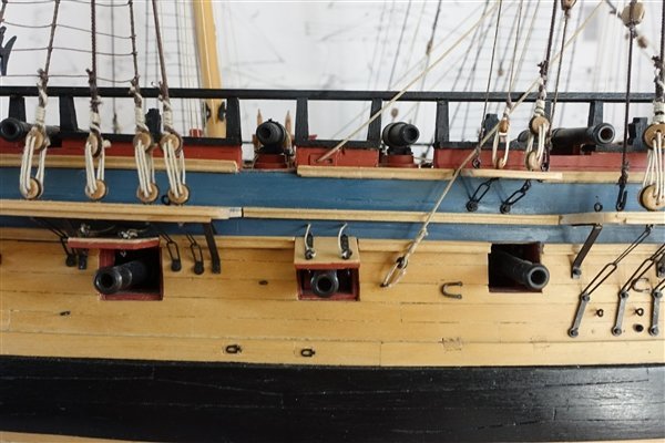
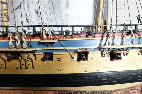
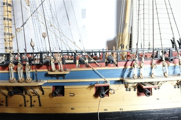
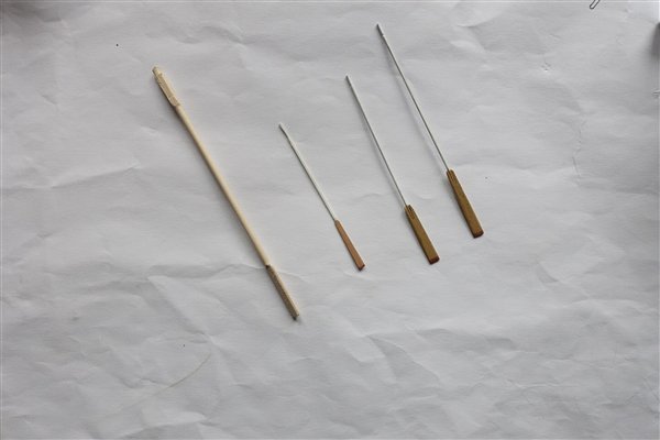
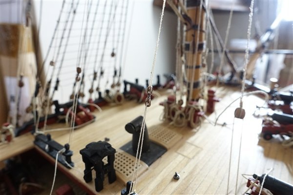
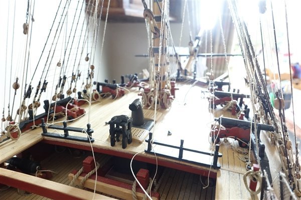
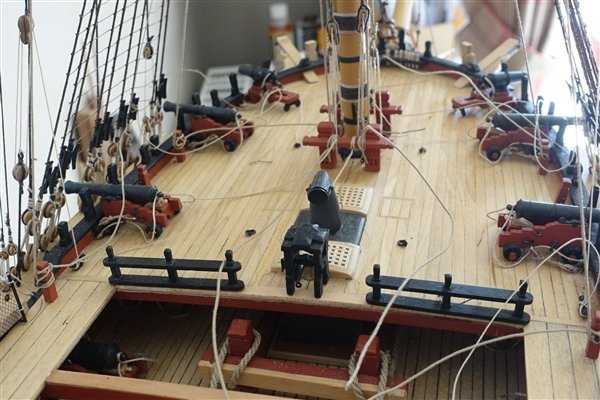
I sent for some longer Amati oars for the cutters but they are pretty ugly and much oversize. I attempted to whittle them down but gave up because they are made from limewood and I thought they wouldn’t stand much thinning down. In the end I made my own from 1mm brass rod and 4x1 tanganyika that I had. They are from the left, Amati, Vanguard Models, my versions for 18’ and 24’cutter. In the meantime my ropes arrived from Ben so I continued with a bit more rigging. Belaying the tacks proved to be less of a problem than anticipated although access under the gangway and around the guns is still tight. However I have run into a problem with the main sheets. The photo below illustrates the problem in that the standing part cuts across the barrel of the carronade. The eyebolt for the standing part is a little close to the gunport lid but moving it aft wouldn’t alter the fact that the rope would still cross the gun. I think this is a consequence of my moving the quarterdeck guns around to fit the open rails. If the gun was a little further forward and the eyebolt a little further aft, I might have got away with it. Too late to change now. My solution is to move the eyebolt forward of the gunport as shown in the photo below. Not ideal but... Thanks for the likes and for looking in. David
- 310 replies
-
- 10
-
-
- Diana
- Caldercraft
- (and 1 more)
-
Thanks Dave. I would like to make my own rope but I don't really have the room. David
- 310 replies
-
- 1
-
-
- Diana
- Caldercraft
- (and 1 more)
-
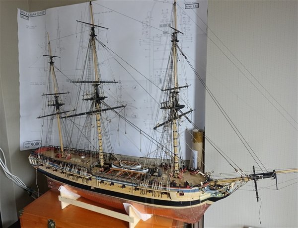
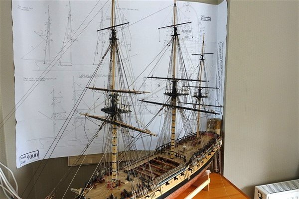
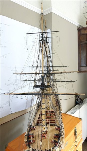
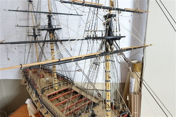
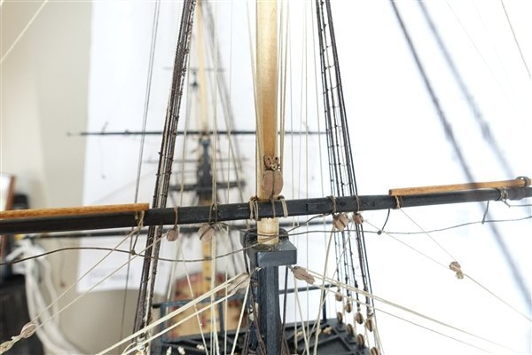
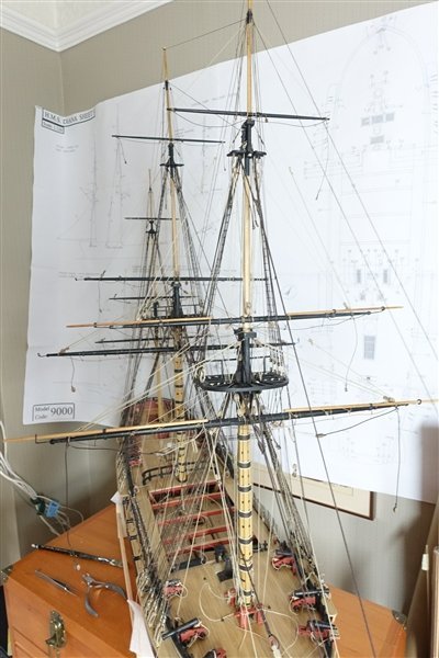
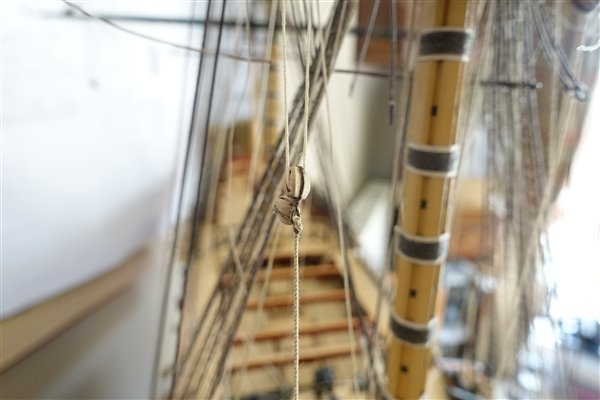
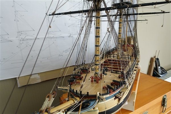
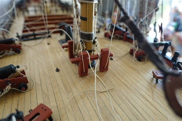
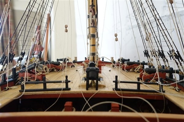
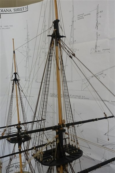
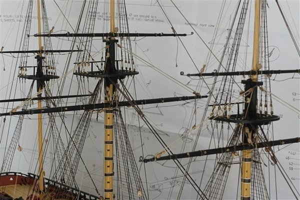
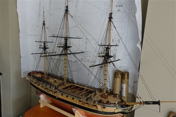
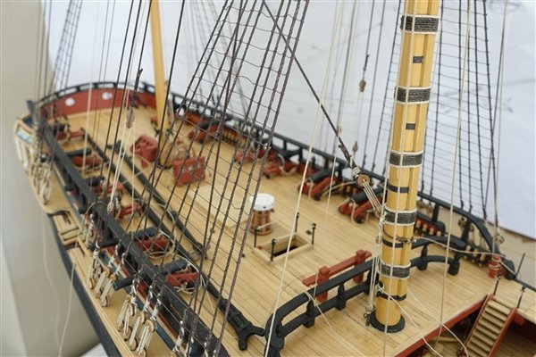
Your likes and comments are much appreciated as always. It’s a few weeks since I’ve updated the log due to commitments in the garden and I’ve had a week away in The Lakes, which has meant a slowdown in work on the ship. I’ve completed the main and mizen mast rigging. Getting clean runs of the rope becomes more of a challenge as I progress and there were a few accidents with already completed rigging along the way. The deck was beginning to look like a nest of snakes so I have also started adding hanks and trimming off the excess rope at the belay points. A few photos follow showing the current state of Diana. For the moment I propose to stop work on the rigging and continue with finishing the ship’s boats and deciding which ones to mount on the skid beams. But I’m in a bit of a dilemma. Should I mount the boats, in which case it could be difficult to tie off the sheets and tacks or add the sheets and tacks, in which case it may be awkward to mount the boats? Diana seems to be gobbling rope at a rate of knots, 😄 -I’m using far more than I anticipated so Ropes of Scale has received another order from me which hopefully will be sufficient to complete the rigging when the time comes to return to it. Thanks for looking in David
- 310 replies
-
- 8
-
-
- Diana
- Caldercraft
- (and 1 more)
-
Thanks to everyone for the likes I have replaced the ropes from the kit that I used with those from Ropes of Scale, so the foremast rigging is completed for the moment. I have left off the brace falls to maintain a clear space amidships for as long as possible. I had fitted the brace pendants according to the plans supplied but they have never looked right to me. Checking with Lees and Steele’s tables, I realised that they were too short so these have been replaced with pendants that are 1/3 the length of the yard and with beefed-up ropes. But before replacing the brace pendants, I have added the yard tackles to the fore course. I have left them hooked to the futtock shrouds and with a reasonable amount of catenation like they are shown in Lees. The blocks for the fore topsail bunt lines are not shown on the plans. It was a bit awkward to the add them as they are tied to the tye block. I also had to add the pendant blocks to the crosstrees. It’s now a case of repeat for the main mast with the added interest of trying to thread the sheet and clew lines through the sheaves in the main jeer bitts. David
- 310 replies
-
- 9
-
-
- Diana
- Caldercraft
- (and 1 more)
-
Dave, I went back and reminded myself what I had done. I also found the guns sat too high in the gun ports but I didn't have your foresight and had already drilled holes for each, which meant a bit of a filling job. The spacing was also a problem and my solution was similar to yours although I spaced ports 7 & 8 further apart. I think the solution depends upon each individual's build. You have also checked the position of the shrouds which I failed to do properly and created a problem for myself when it cam to the quarterdeck guns. All in all, I think that you found the best solution for your Diana and it will look great David
-
I've been wondering what my next model would be. It needed to be smaller than Diana as I'm running out of room and now I think that I've found it. David
- 57 replies
-
- 6
-
-
- Trial
- Vanguard Models
- (and 1 more)
-
Thanks for all the likes and comments. Trincomalee was fully open this time so I was able to visit quarter deck and forecastle. Anchor stocks are tapered as per my general understanding so strange why they don't appear to be in the AotS drawings. Anyway moving on... I have completed the last of the ship’s boats, the 18ft cutter and I’m quite disappointed with the result. It all started very well and for the first time, there were no bits breaking off the delicate keel or stern pieces. I was also pleased with the way the second layer of card representing the clinker planking went. However, after the bulkheads were removed the boat has seemed to spread across its width making the transoms too narrow. I also had problems fitting the brass etch gratings especially at the stern which, in contradiction to my previous thought, needed trimming to size. It’s finished now but I might scrap it, buy another from Chris and have a second go. The ropes have arrived so it’s back to the rigging. David
- 310 replies
-
- 11
-
-
- Diana
- Caldercraft
- (and 1 more)
-
Andrew, I have that plate in the 'Arming and Fitting...' but it looks as if the stocks are only tapered by virtue of the clamped ends. However there is a picture at the bottom of page 31 that clearly shows the tapering of the two halves of the stock. I shall leave well alone. I am going for away for a few days next week for some birdwatching around Teeside and I will also be making a return visit to Trincomalee. On my last visit, the upper deck was closed for maintenance. Although built 20 years after Diana, I will be taking special note of the anchors. David
- 310 replies
-
- 2
-
-
- Diana
- Caldercraft
- (and 1 more)
-
Thanks very much Andrew, very kind of you to say so. I too have previously clamped them tight and tapered them along the length. The AotS has been very helpful in getting the details right on Diana David
- 310 replies
-
- 1
-
-
- Diana
- Caldercraft
- (and 1 more)
-
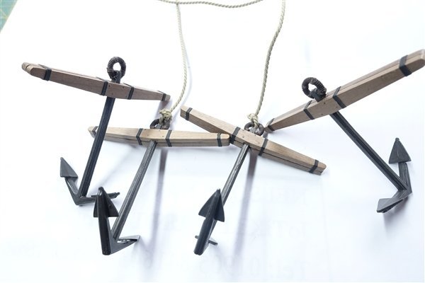
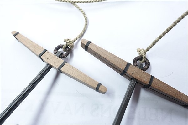
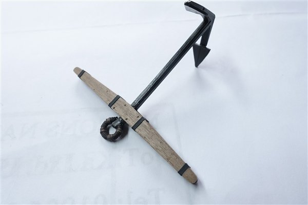
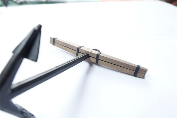
Thanks everyone for the likes While I’m waiting for more rope, I have put together the anchors that come with the kit. They look the right size and shape according to the AotS and the stocks are in two pieces. The cast metal anchors needed a bit of cleaning up but weren’t too bad. I had always understood that the stocks tapered across the thickness as well as along the length, but this doesn’t seem to be the case looking at the AotS plans. They do clearly show the gap between the two halves of the stock is easily achieved with a bit of sanding of the housings for the shafts. I drilled small holes for the bolts and the treenails with a 0.5mm bit and then sanded the faces leaving the dust in the holes and sealing them with dilute matt varnish. They are barely visible which I think is at it should be. The bolts are the usual dabs of CA gel painted over with iron grey. I cut 2mm ‘iron bands’ from heat-shrinkable tubing, which conform nicely to the taper of the stocks when a hairdryer is used to shrink them onto the stocks. I used 0.6mm dark brown rope for the puddening of the ring, which is 1.5mm brass rod and blackened with brass black. I added the four seizings to each ring but they are hardly noticeable and are not as neat as I would have hoped. Perhaps if I had used a finer or softer rope the seizings would have been more regular. Anchor cable is 2.8mm which is tied with an attempt at an inside clench knot and a couple of seizings applied. There are no stream or kedge anchors in the kit so I will need to order some from CMB. Still waiting for the rope to arrive from Canada (which was dispatched next day) so I'll start the last of the ship’s boats now, the 18ft cutter. Thanks for looking in David
- 310 replies
-
- 10
-
-
- Diana
- Caldercraft
- (and 1 more)
-
Thanks everyone for the likes. Topgallants are now all fitted. The parral beads that I have are all too big for topgallant yards and in any case, would have been too fiddly to fit, so I’ve attached them with truss parrals as a valid alternative according to Lees. Ties and lifts are also added. I now return to the fore yards to add clues, tacks, buntlines and leechlines. The clue block and sheet block are are joined together and the tack threaded through and held by a tack knot. The tack knot I approximated with a figure-of-eight with an extra turn. The clueline is tied to the yard just outboard of the block on the yard with a timber hitch, runs through the clue block up to the yard block and then is taken through the fore and aft inner blocks under the top and down to the middle sheave on the fore bitts. I’ve found a potential problem with the blocks under the top The only double block I placed was the inner block with the other two being singles. It would be quite difficult to replace the blocks now so I hope that it won’t cause me problems later on. The tack will run down to a block on the boomkin but for the moment I have loosely tied them off to the cathead. I will also add the sheet later to keep the midships area free. clue block, sheet block and tack tied together clue garnets tied off to fore bitts tack lines temporarily tied off to catheads Buntlines caused me to stop and think for a while. I found Lees descriptions of buntline legs and falls difficult to follow. I wasn’t sure if buntline falls were required In the end I went for two blocks stropped together for the falls. The buntline legs are tied with a toggle to stop them running through the block on the yard and then lead through the forward blocks under the lower top down to the fall block, back up through the afterward block under the top and end at the second yard block. One end of the falls is tied to the forecastle rail runs through the lower fall block and back to the rail. The leechline a toggle prevents it running through the block on the yard it roves through the outer block under the lower top and a block is seized in the lower end. A whip is tied to the forecastle rail, passes through the block in the end of the leechline and runs back to the rail. I ran out of 0.25 and 0.35 ropes from Ropes of Scale for the buntlines and leechlines so used the kit-supplied thread but standing back, the contrast between the two (perhaps not obvious in the photo below) is not acceptable so I have sent off to Canada for further supplies to replace them. Thanks for looking in
- 310 replies
-
- 9
-
-
-
- Diana
- Caldercraft
- (and 1 more)
-
Glad to hear your mum is OK and hope she fully recovers soon. Planking is looking very good. David
- 443 replies
-
- 3
-
-
- Indefatigable
- Vanguard Models
- (and 1 more)
-
Lovely work David. She really is that tall! Did you go with the long. common or stump pole head? David
-
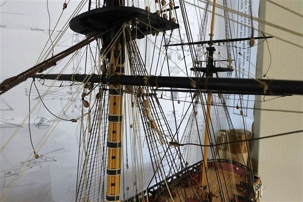
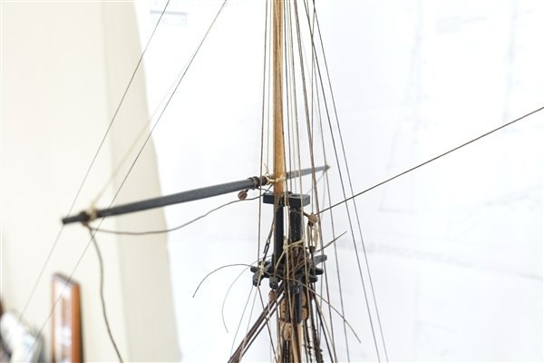
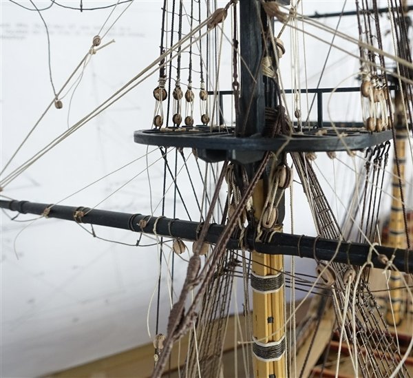
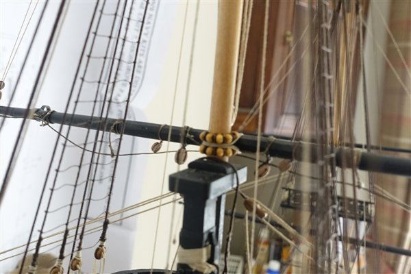
Thanks for the likes and comments. Thanks Dave but the separate oars that Chris sells are too short. For single banked boats they should be 2.5 times the beam so at least 12mm for my boat. After the interlude of making the 24’ cutter, I’m off my crutches and mobile again so it’s back to the main ship and adding the topsail yards. The yards were made a while ago with the blocks, stirrups and horses completed. I began with the mizzen topsail yard and the parrals (or is it parrels, I’ve seen both spellings?) The kit supplies some black beads for the trucks but they are quite round rather than more barrel shaped. I searched all the bead sites looking for seed beads that are a better shape but have found nothing. I ordered some bugle beads but they are too cylindrical. In the end I had some wooden beads in my box of bits that I decided to use, although they are still not as they should be. The ribs are blackened brass ones left over from HMS Fly. The parral rope is threaded over the yard and the ribs and trucks threaded on taking care to keep the ribs the right way round. The yard is pinned to the mast and glued with CA simplifying the job of fitting the parral. The ropes pass around the mast, over and under the yard and then back over the groove in the ribs. This is repeated two or three times and then tied off around the yard in a simple knot. The tie is next, which on the mizzen threads through a single block up through blocks suspended each side of the mast head and ends in long tackle blocks to come below the lower mast top. The lower block of the halyards is hooked to an eyebolt on the stool. The rope is tied to the long block runs down to the lower block through the long block back up to the long block and is tied off at the cavil block. The lifts a long strap with an eye in each end is clove hitched around the cap. The lift is hooked into the eyelet runs down to the sheet block and back up to the sister block then down to the pin rail where it is tied off. The parrals of the main and fore topmast yards are rigged in the same way as on the mizzen topmast. I chose to follow Petersson in rigging the tie. A double block is tied on each side of the topmast head on a long strop. I think that these two blocks should be on the same strop which is then tied around the mast head. I couldn’t do it like this because the topgallant is already in place so separate strops it had to be. The tie has an eye spliced in one end and passes around the topmast head, through the eye and down to the double block on the yard. The port tie passes through the forward sheave and the starboard the aft. The halyards are tied off to eyebolts on the main mast stool just forward of the aft-most topmast backstay. The lifts on both fore and main topmast yards are set up in a similar fashion to the mizzen mast. The main lifts coming down to the barricade and the fore lifts to the cleat on the third shroud. David
- 310 replies
-
- 14
-
-
- Diana
- Caldercraft
- (and 1 more)
-
Thanks Allan your praise and encouragement is much appreciated David
-
Thanks Andrew. If that ratio of case to kit price holds true for Diana, I'm in trouble! David
- 206 replies
-
- 1
-

-
- Vanguard Models
- Brixham trawler
- (and 2 more)
-
Nisha looks very happy in there Andrew. Did you make the case yourself, or is it custom made? David
-
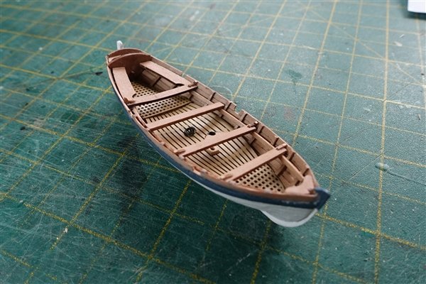
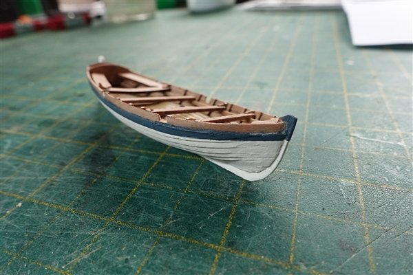
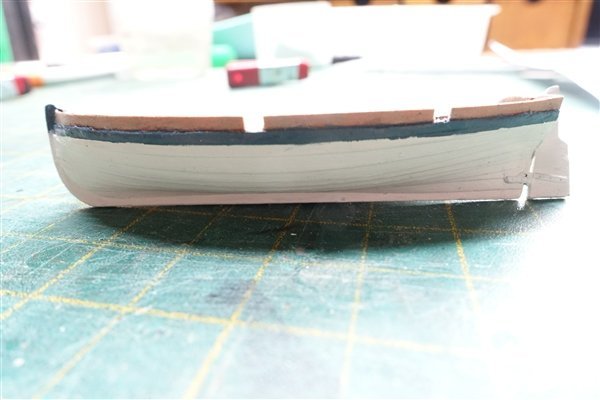
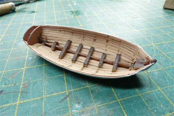
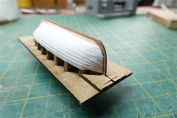
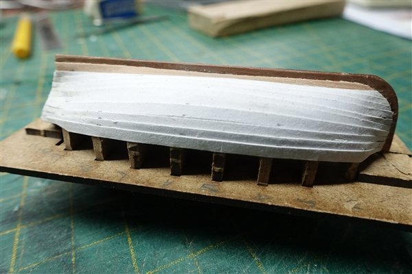
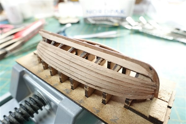
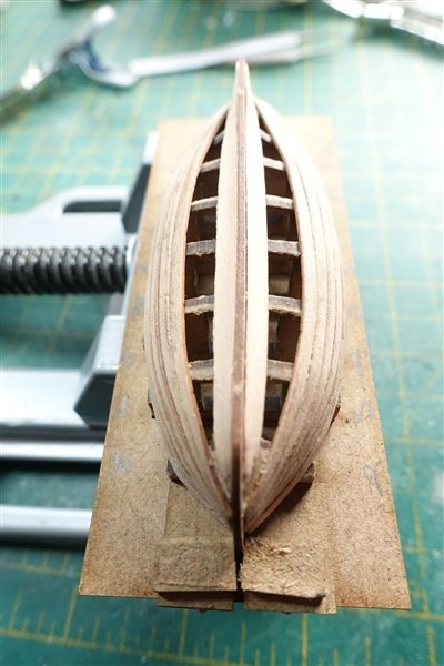
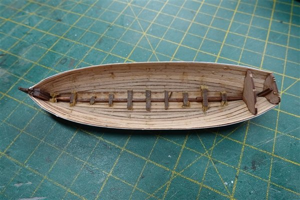
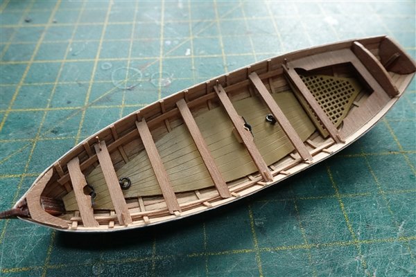
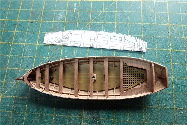
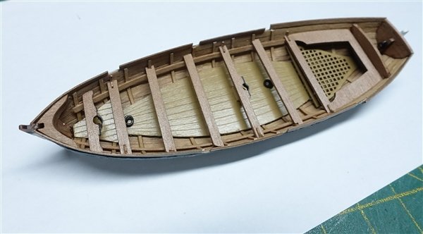
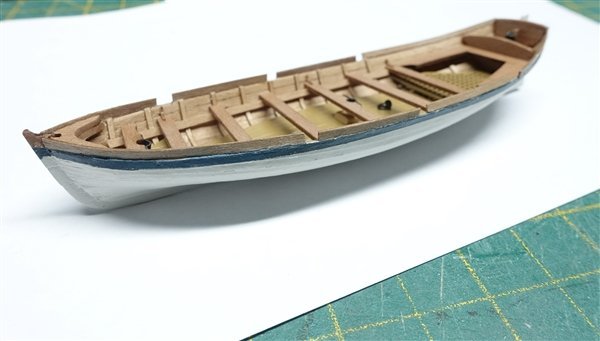
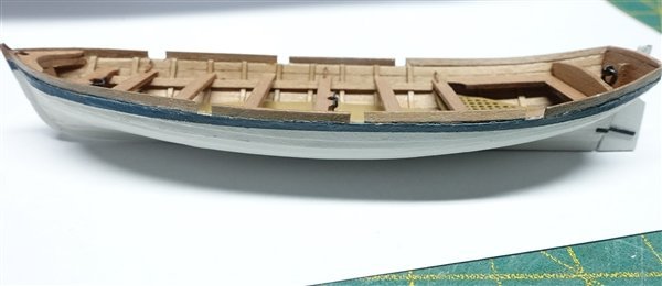
Thanks for the likes and comments: always much appreciated. The bulkheads came away quite easily – a bit too easily in places as a couple came out in their entirety and I had to cut back and glue in the floor supports. Because I mostly just used glue between the planking, clean up was much easier this time around. The ribs were placed as previously using Tamiya tape to give even 6mm spacing and the transom supports were fitted using a scap piece of 4mm strip wood as a guide. I followed the AotS Diana’s plans for the cutter which shows it to be single banked and shows only three knees per side – a blessing as they are so small and fiddly to sand and fit. I copied the half deck plan from the book to give me a guide for the placement of the transoms an correct positioning of the main mast step and eyebolts. Two pieces are provided for the breast hook (CFT26) where only one is shown on the plans but it looked a neater finish with both pieces in place which I then sanded back to look more like one piece. Rather than cut into the hull sides for the rowlocks as the instructions show, I added the wash strakes using some left over planking strips. There’s not much for these to stick to but they are surprisingly firm once the glue has gone off. I thought that this change might make the boat higher sided than it should be but compared to the AotS cross section, the finished boat is less then 0.5mm higher which I think is fine. I painted the hull in Valejo off white based on other contributors recommendations. Comparing the cutter to the pinnace and launch that I made before, I have to agree with them so at some point I will be repainting the other two boats to match. Because I have made the cutter single banked, the provided oars are too short. Steele gives a table of oar measurements for beam widths of between 4 and 7ft but also says that oars can be between 2 and 3.5 times the beam. I will think about what length might be in proportion and make a set but that’s for another day. Thanks for looking in David
- 310 replies
-
- 7
-
-
- Diana
- Caldercraft
- (and 1 more)
-
Thanks for the compliment but not my idea Dave. Just following the master! David
- 310 replies
-
- 2
-
-
- Diana
- Caldercraft
- (and 1 more)
-
Thanks Jason, and thanks again for posting your method for clinker planking. David
- 310 replies
-
- 1
-
-
- Diana
- Caldercraft
- (and 1 more)