HOLIDAY DONATION DRIVE - SUPPORT MSW - DO YOUR PART TO KEEP THIS GREAT FORUM GOING! (89 donations so far out of 49,000 members - C'mon guys!)
×


dunnock
-
Posts
523 -
Joined
-
Last visited
Content Type
Profiles
Forums
Gallery
Events
Everything posted by dunnock
-
Thanks Andrew but you didn't need to go as far as Menorca - 30deg here today and I'm enjoying a glass of wine in the garden contemplating the new wildlife pond I'm going to have to dig this week. Progress on Trial may slow down - unless I can persuade someone that it's too hot for digging and it would be safer to do something in the shade! Enjoy your holiday. David
- 152 replies
-
- 2
-

-

-
- Vanguard Models
- Cutter
- (and 2 more)
-
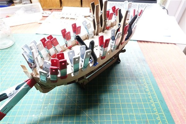
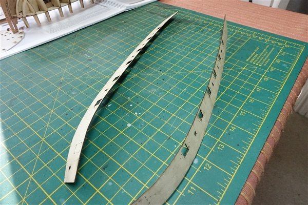
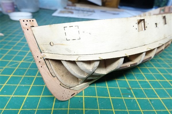
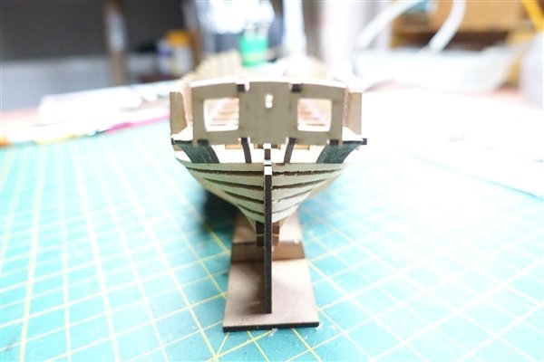
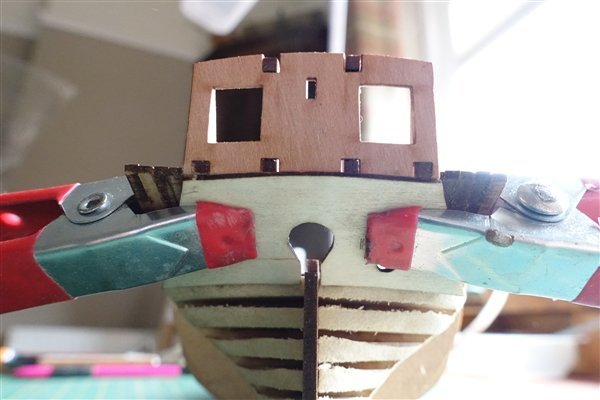
Schoolboy Error. I carefully lined the horizontal etched line of the bulwark pattern with the level of the false deck and clipped the pattern at every bulkhead. I applied a bit of heat to set the shape and all looked good so I glued it up and even added the first of the limewood planks. Then I noticed a 2mm gap at the slot in the prow. Checking the manual, I realised that I had not read instruction 44 properly which says’ the lowest line (my underline) should be placed at the top edge of the false deck’. Thankfully the plank and bulwark patterns came off without any damage occurring and are now placed in the correct position. The first plank below the bulwarks have also been added. A small amount of tapering at bow and stern and some edge bending at the bow is required for the planks to sit correctly. As it says on the first page printed in red, ‘take plenty of time to study this manual’. Lesson learnt! David

- 152 replies
-
- 8
-
-
- Vanguard Models
- Cutter
- (and 2 more)
-
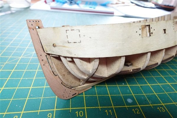
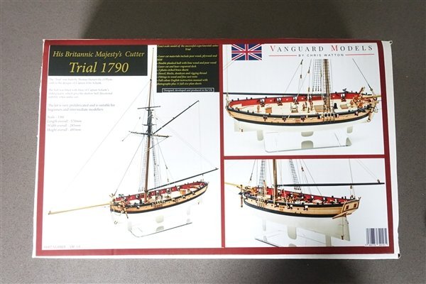
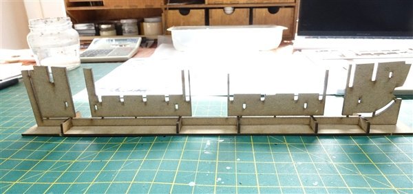
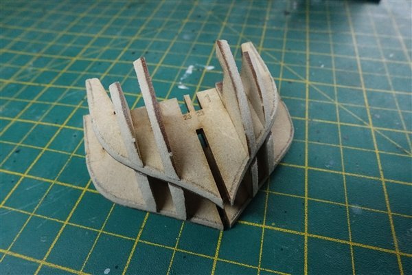
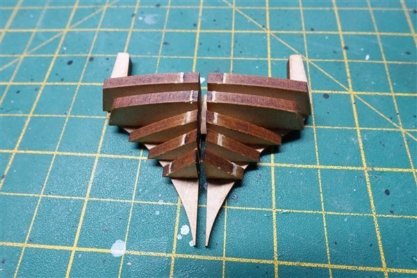
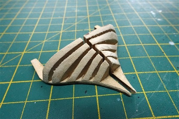
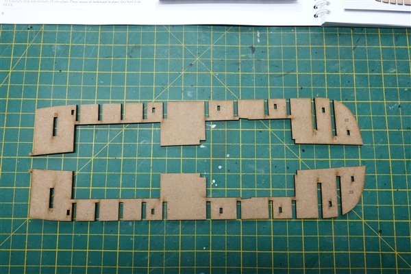
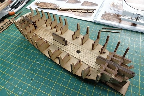
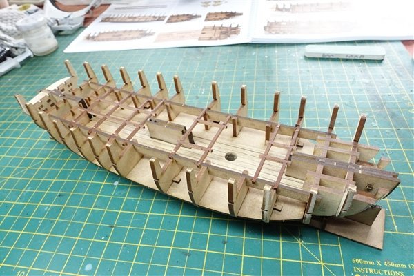
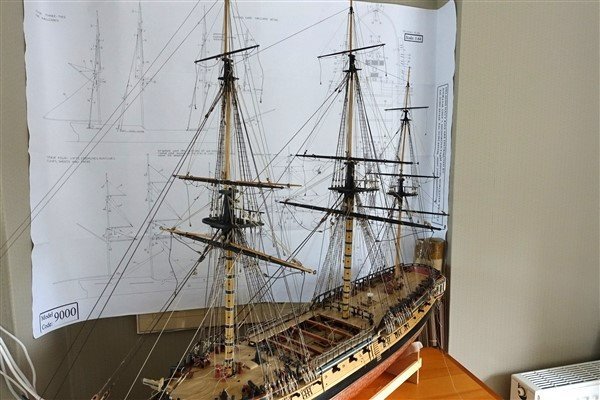
A lovely package arrived from Vanguard Models arrived the other day. I have built ships boats and some of the deck furniture from Vanguard but this will be the first of Chris’s ship models that I have built and I was excited to get started. The box contains a comprehensive (70 page) photo-illustrated building manual, 11 sheets of plans and part diagrams as well as numerous sheets of mdf, pear-wood, PE brass, strip wood, dowels and stand on which to display the finished model. Andrew (AJohnson) has already posted photos of the contents of the box so I won't repeat it here. The build starts by making a cradle for the initial stages of building up the hull structure. It looks delicate but is more robust than it appeared when removed from the mdf sheet. The bulkheads drop nicely into the keel without any need for sanding. I found it easiest to begin the preliminary sanding of the bow section bulkheads with parts 15 and 16 fitted (but not glued) in place. Once bevelled parts 15 and 16 are put aside until later. Chris’s manual shows the bulkheads being bevelled using a Dremel. I’m not so brave but it doesn’t take long to sand them back by hand. The stern assembly is next up and once glued and sanded back, it required a little bit of easing to slot into the keel. The centre-line patterns are given as 14 in the book but are numbered as 23 on the parts themselves. I fitted and glued the lower deck (part 25). Belatedly, I then decided to put some strips of planking down the centre line. They probably won’t be visible when the final deck is in place but I may want to have some of the hatches open. Once the longitudinal bracing parts are slotted and glued in place the whole structure firms up nicely. I sanded and applied a couple of coats of matt varnish to the deck beams and ledges before gluing them in place. The stern frames are next to be added but first I sanded off the char from the parts that are later to be painted. Part 85 is the inner layer of the stern transom and the book advises that the design was changed to make it less delicate, however I still managed to crack it when I removed it from the sheet. Luckily it didn’t break in two so I was able to glue it and no harm done. The inner stern counter pattern is fitted next. I gave it a quick dip in water and clamped it in place and left it to take up the slight curve of the hull. Other builders of Vanguard kits have said how well they go together and HM Trial is no exception. The kit is very well thought out and goes together without any need to fiddle around sanding back bulkhead slots or worrying that everything is square and correctly fitted. The last couple of days have been a joy. David
- 152 replies
-
- 13
-
-
- Vanguard Models
- Cutter
- (and 2 more)
-
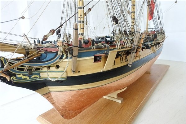
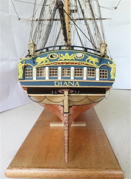
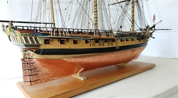
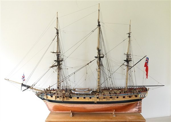
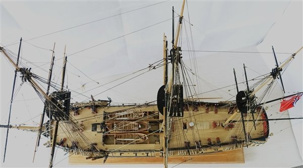
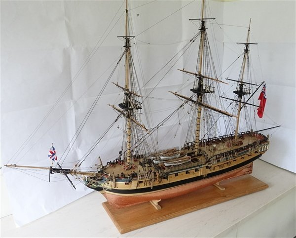
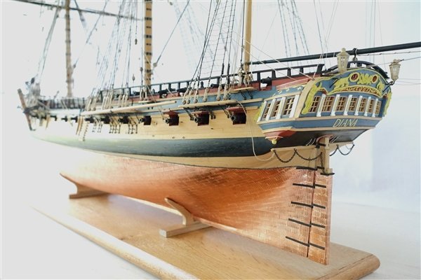
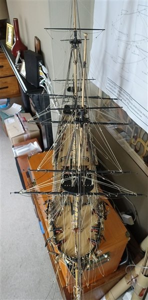
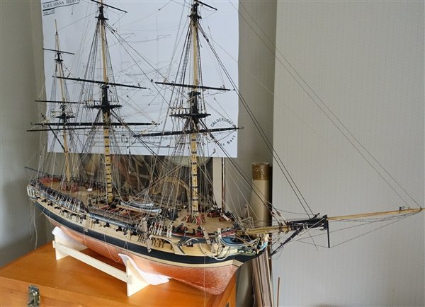
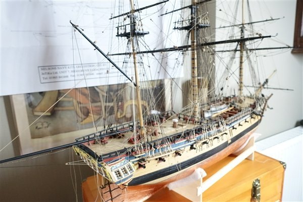
Thanks again for all the likes and generous comments. Diana is the biggest and most complicated ship that I have built but I've really enjoyed the challenges that it presented. Although it took a lot of time and some hair pulling, I'm glad that I went with the open rails on the quarter deck and my thanks go to Ray and Robdurant for showing me the way. Also my thanks to the many others on these forums that have posted tips, help and advice that I have shamelessly copied. I've managed to take some better photos of the finished model which I've added below. I hope I haven't overdone it! Thanks all for looking in. I hope to see you again on my log of HM Cutter Trial David
- 310 replies
-
- 22
-

-
-
- Diana
- Caldercraft
- (and 1 more)
-
Dave, My understanding is that glass would be heavier even if I might be able to use thinner sheets. The density of glass is about twice that of acrylic sheet. Also I would be quite nervous of handling the size of glass sheet I need. David
-
Mugje, Thanks very much. I particularly like the Tamiya Blue even if it's not that easy to apply. Once again many thanks Andrew. I had a good start on the boats by using Vanguard's kits and modified them according to The AotS DIana David
-
Thank you very much B.E. but however good it may be is no small part due to your inspiration and the many tips and techniques that I've picked up from your logs and particularly from Pegasus.
- 310 replies
-
- 1
-
-
- Diana
- Caldercraft
- (and 1 more)
-
Many thanks for your kind words Andrew. I have been looking around a bit more and I think that you are right, the case will have to be at least 5mm thick acrylic. I priced a couple of custom-made cases and they are very expensive. I made a smaller case for HM Cutter Hunter but have never tackled on of the size need for DIana. I have completed a new stand so I now have the final case dimensions and will order some sheet next week. David
- 310 replies
-
- 1
-
-
- Diana
- Caldercraft
- (and 1 more)
-
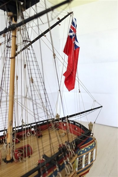
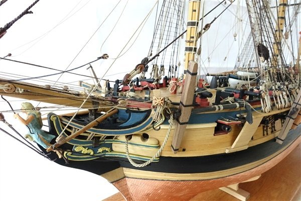
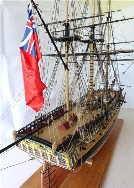
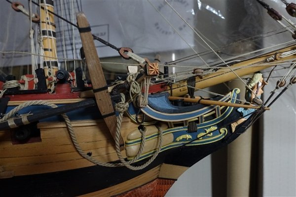
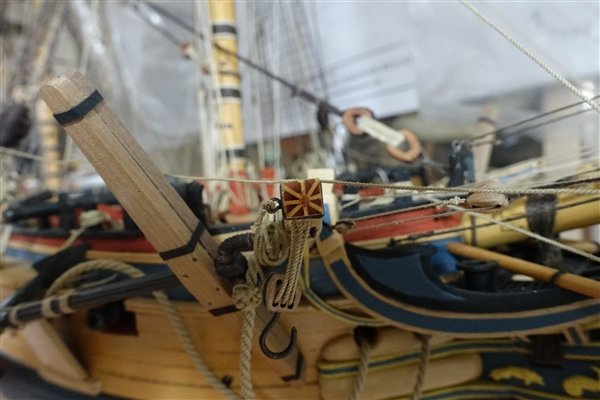
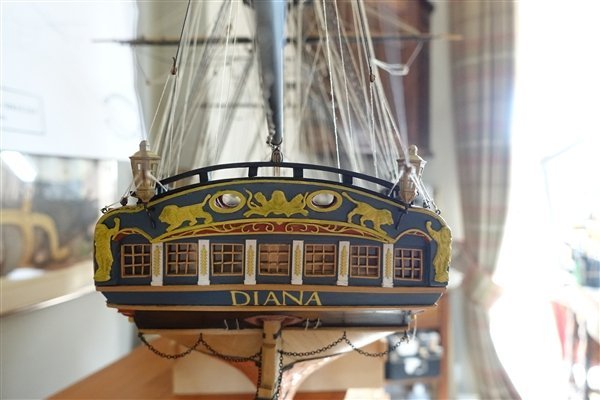
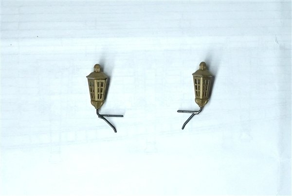
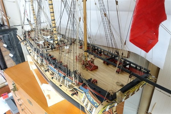
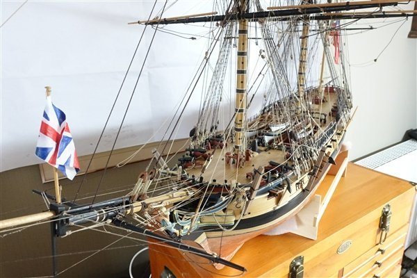
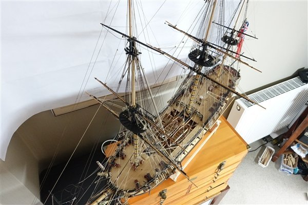
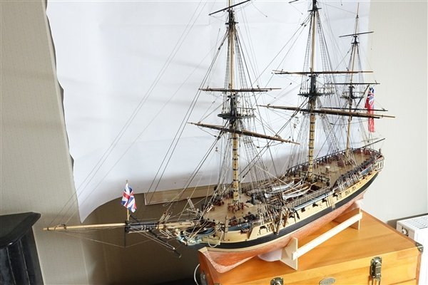
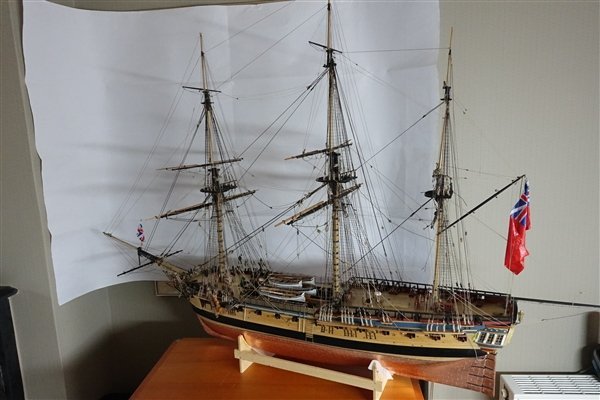
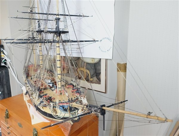
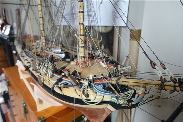
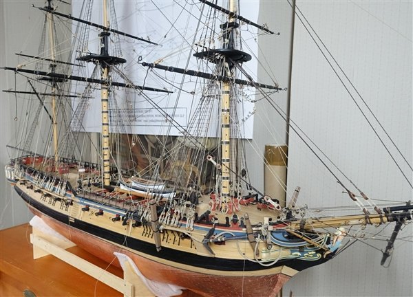
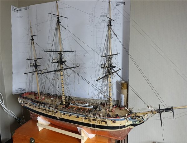
I see that it’s been over a month since I last posted an update but there’s been a lot going on over the summer with holidays and things to do in the garden. I had two weeks on a birding trip in Brasil in the last half of July which resulted in 1500 photos to go through – making progress but still not finished. In between times I have been doing some work on Diana, mostly tidying up but after much procrastination and with full approval from my wife, I have mounted the remaining ships boats. I made a star decoration for the catheads using styrene rod and strip (with acknowledgement to B.E. for his method and description in his Pegasus blog). A pair of Chris Watton’s stern lanterns have been fitted. The lanterns are mounted on brackets formed from 1mm brass rod soldered and then blacked. Last but not least, my daughter, who has a much steadier hand than I, painted the ensign and union jack on tissue paper which I have steamed into shape and hung. The flag dimensions were taken from a copy of Flags for Ship Modellers by Alec Purves. A range of sizes is given for the period and I chose what seemed the most in proportion to the ship, that is scale 128x67mm for the ensign and 43x24mm for the jack. AotS Diana lists an ensign staff of some 35’ but I imagined this getting in the way of the boom so have raised the ensign on a halyard from the gaff. The jack staff is 15’5” or scale 73mm but this was a little short for my flag so I have increased the length to 80mm. Several repairs to rigging have had to be made owing to my clumsiness when manoeuvring the ship and I also damaged one of the stern lights. I am waiting a replacement from Vanguard Models. At the same time I have taken the opportunity of ordering my next project, HM Cutter Trial. I’m now eagerly awaiting delivery from UPS. I now need to make a display case to keep Diana safe from further damage and dust. A glass case of the required size about 1280x850x500mm is going to be very heavy and expensive so I’m planning to make one using acrylic sheet but I’m not sure what thickness of sheet to use. I was thinking 5mm but perhaps I can get away with thinner. If anyone has any experience of cases in acrylic, I be interested to hear your thoughts. I’ll write something of a conclusion on the build and post some better photos of the finished ship when I have been able to set up a suitable backdrop. In the meantime thanks to everyone who has been following this blog and for all the encouragement, help and support that you have given me over the last two and a half years. David


- 310 replies
-
- 12
-
-
- Diana
- Caldercraft
- (and 1 more)
-
I'm thinking that this will be my next project after Diana and hope to start within a month so I'm following with interest. David
-
Many thanks for the compliments Dave although I find getting a realistic 'weight' to them is quite difficult. I think that the hanks and coils are definitely a work in progress David
- 310 replies
-
- 1
-
-
- Diana
- Caldercraft
- (and 1 more)
-
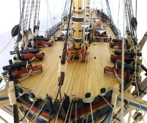
Thanks as always for looking and for the likes and comments The blocks arrived from HiS Model and the ropes from RoS so I was good to go with everything to complete Diana. The catfalls are rigged although I had move some of the belay points around because I had wrongly rigged the jib boom guy. The spritsail yard rigging was completed with sheets and clue lines and then I moved on to the boom and gaff. These were completed, as with the rest of the rigging, following Steel, Lees and the AotS as closely as I could. The only issue I met was with the main yard braces. In all of the references, the belay cleat is sited forward of the sternmost carronade, meaning the running part must somehow pass the gun in order to reach the belay. This doesn’t seem sensible to me. If I have this wrong or their is a better solution, I would be interested to hear. Now I have a lot of tidying up of the lines to do, hanks to make and then some finishing touches like adding stunsail booms, stern lanterns and the remaining ship’s boats. I now have an enjoyable dilemma of which will be my next ship model? It could be HMS Trial when available or the new version of Speedy or maybe HMS Flirt. A few weeks yet to think about it. David
- 310 replies
-
- 8
-
-
- Diana
- Caldercraft
- (and 1 more)
-
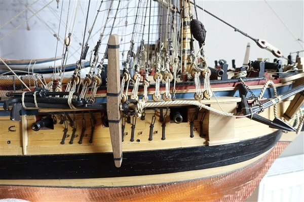
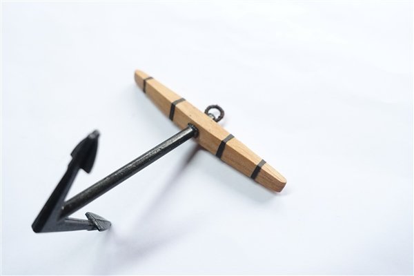
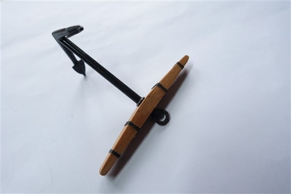
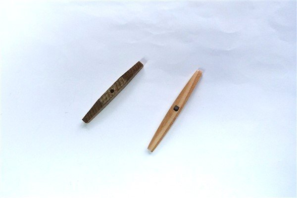
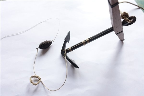
Thanks everyone for the likes. Starboard bower anchor is completed. There is no stream or kedge anchor supplied in the kit so I bought the nearest I could find to the patterns in the AotS from CMB. The stock supplied with the stream anchor was too short and heavy looking so I fashioned a replacement from a piece of 5mm square spruce. I stained the finished stock with ‘Jacobean Oak’ and used heat shrink tubing for the ‘iron’ rings. The finished anchor is lashed to a bower anchor before fixing it to the forward channel. The kedge anchor is lashed to the sheet anchor in the folded position according to the illustration on page 235 of ‘Seamanship in the Age of Sail by John Harland. Harland states that the sheet anchor is tied against the starboard forward channel with the anchor cable fixed and running to the outer hawse hole. I’m waiting for some 7mm triple blocks for the cathead falls to complete the anchor set up. The boomkin stays have never looked right to my eye with only one stay fixed with 0.5mm rope. Checking with Steele, 0.8m would seem more appropriate and I believe that there should be two stays on each side for this size of ship. I have changed them accordingly and am now much happier with the result. Thanks for looking in David
- 310 replies
-
- 9
-
-
- Diana
- Caldercraft
- (and 1 more)
-
Thanks David, Yes I used Gutterman dark brown thread. The ratlines take a lot of thread so it would be expensive to use anything else. David
-
https://www.hismodel.com/ Based in the Czech Republic. Good range of accessories and very reliable in my experience David
-
David, I can feel your frustration. I felt much the same when working on Diana's shrouds but yours look great so it was worth the effort. David
-
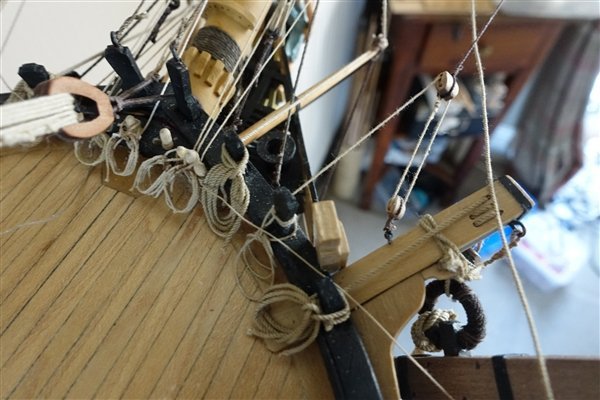
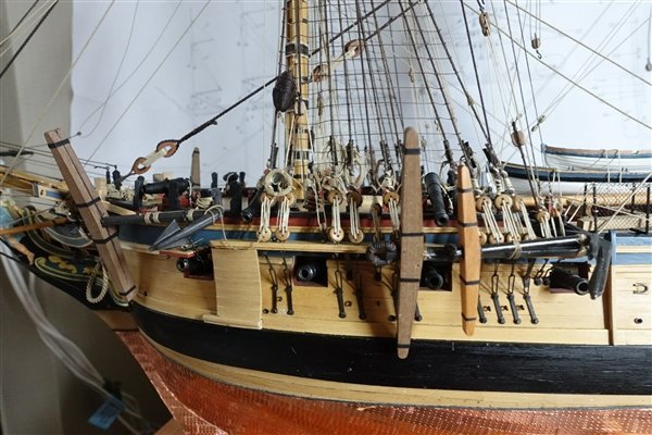
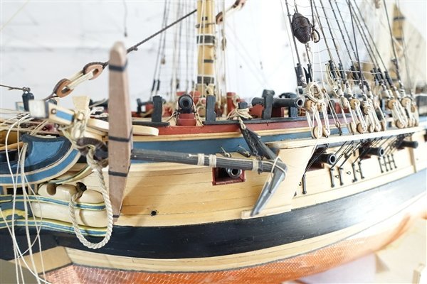
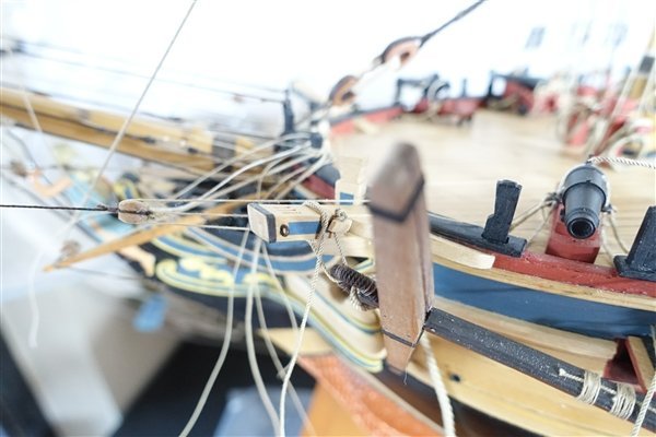
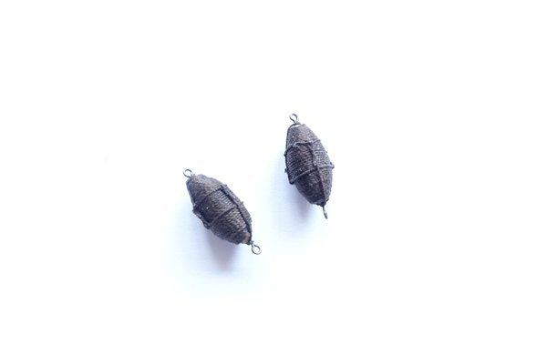
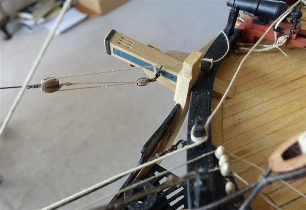
Thanks to all for the likes and encouragement. I made up the four bower anchors a while ago but now seems the right time to add them to the model. I thought that I would have a go at making the anchor bouys for the to add a bit more detail to Diana. I used 8mm limewood dowel as the basis for the bouys and roughly carved them with a scalpel and then finished with sandpaper. Lavery shows four rope slings coming from top and bottom of the bouy with an eyelet seized to take the lanyard and anchor rope. I decided on a simplified route and fitted eyebolts in each end. The form is served with Gutterman polyester thread which is about 0.3mm. I found it easier to wrap the thread from each end towards the middle. Another simplification I made is to add only two slings from each end, both for the sake of sanity and because four slings looked overcrowded to my eyes on this small bouy. The slings are threaded around the hoop and fixed with a false splice. The lanyard 0.25mm, is tied to one end and the anchor rope 0.45mm is spliced to the other. The anchor rope tied around the anchor flukes and then held to the shaft with three seizings. The excess rope is coiled and held with four ties around its circumference. The anchor is tied to the model with the cathead stopper. A 6mm rope with a stopper knot in one end and threaded through the anchor ring. I wasn’t entirely sure of the arrangement of the stopper but I have placed the knot in the cleat on the aft side of the cathead and passed the other end through the ring and tied it off around the cathead. The shaft is held close to the fluke by a length of chain fixed to an eyebolt in the end of the forward channel. A length of 0.6mm rope is spliced to the other end. The chain wraps around the shaft and the rope is tied off to the timberhead. The coil of anchor rope and bouy are tied to the shrouds. The port (best bower?) is completed with the anchor cable threaded and fixed through the hawse hole. Moving on to the starboard… Thanks all for looking in David
- 310 replies
-
- 8
-
-
- Diana
- Caldercraft
- (and 1 more)
-
Amazing work Jason and a great to see your thoughts behind the process David
-
Thanks Andrew but I'm just borrowing the ideas of Blue Ensign Dave - no problem and thanks for your compliments. No air brushing just ordinary artist's paint brushes. I tend to dilute the first couple of coats and light sand in between and then just build up the layers until I'm happy. The blue is Tamiya Medium Blue XF18. The colour is nice but the solvent based acrylics are very fast drying. I've not tried but it may be an improvement to add Tamiya Retarder to slow the drying down. David
- 310 replies
-
- 3
-
-
- Diana
- Caldercraft
- (and 1 more)
-
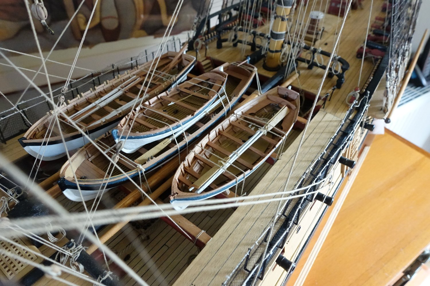
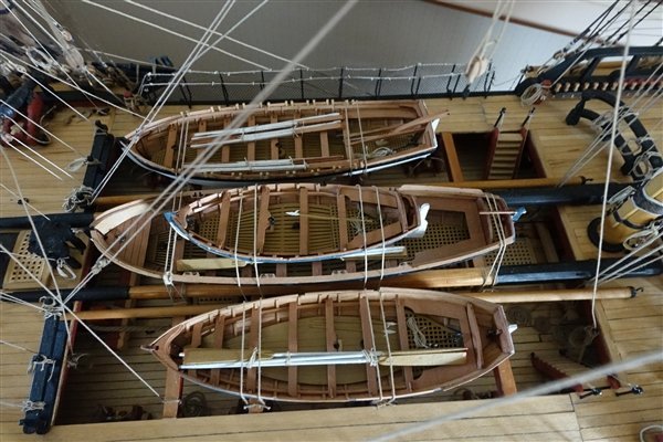
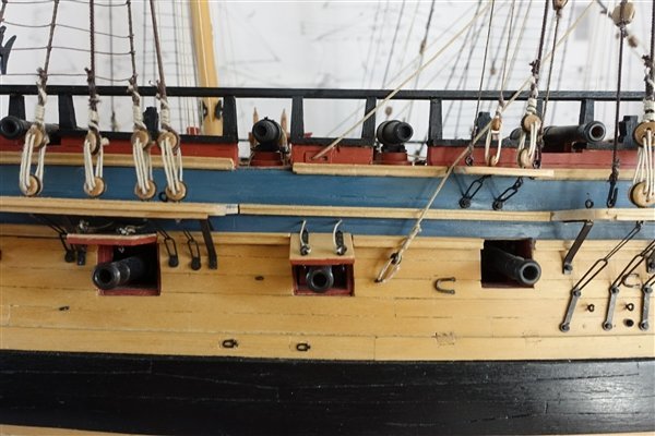
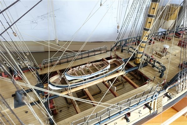
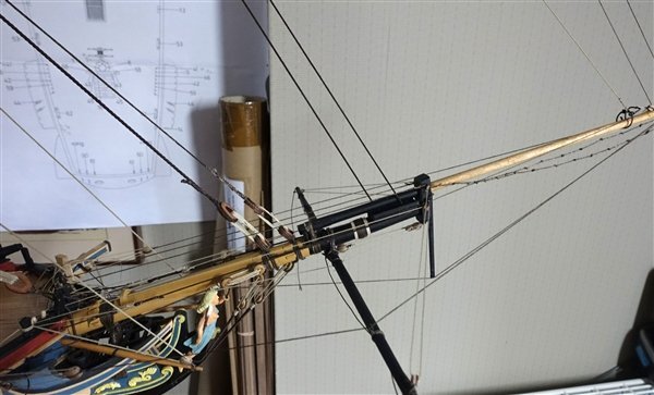
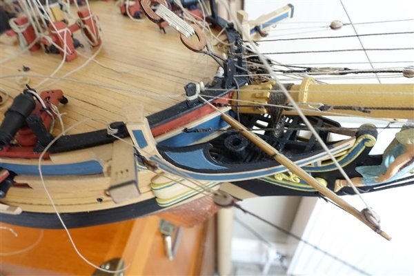
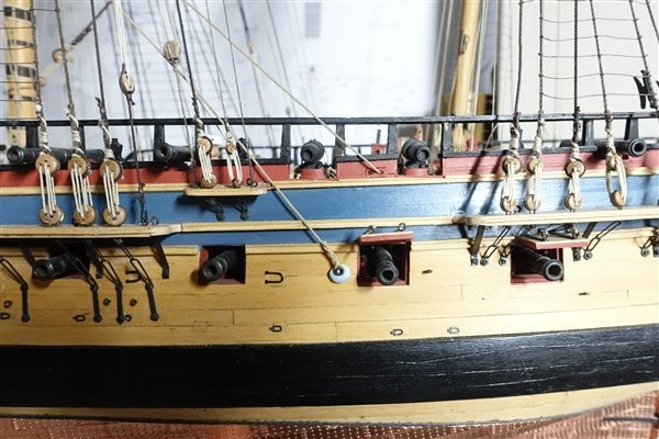
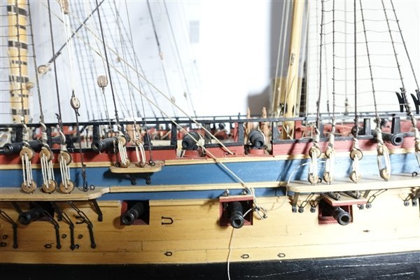
Thanks for the likes. Appreciated as always. Rather than move the eyebolt which would leave a hole to be filled that might be obvious, I added another on the forward side of the gun port to accommodate the main sheet standing part. Sheets and tacks now completed. The pinnace has been tidied up and is lashed to the spare topmasts in the waist. I have also nested the 18’ cutter inside the pinnace. I am still undecided on how to mount or display the launch and 24’ cutter but I have glued the boat cradles in place. The stay tackles have been added. Getting them to hang realistically took some time and I eventually followed BE's lead on Pegasus and propped up the stay with scrap dowel before applying dilute pva to the rope and weighting with clips. On to the spritsail yard. The sling was made according to the second option in Lees; putting an eye in one end and threading the other end through and seizing it to itself. I used 5mm Amati rope served with Gutterman thread. I had missed adding the eyelets for the jibboom guys and the yard lifts off model so now added them. As with the other yards, I replaced the brace pendants with a longer version of 8mm. The spritsail yard halliard consists of a 5mm long block and a 5mm single block. The fall runs to the starboard side of the pin rack at the bow. It’s a bit tricky tying off here with little room to manoeuvre. I used 0.45 RoS rope for the jibboom guys. They have a 5mm block seized to the end. The falls thread througn this block, through another seized to an eyebolt on the forward side of the cathead and tied off at the timberhead. Spritsail lifts are rigged with the standing end seized to an eyebolt at the bowsprit cap. The running end passes through the block on the yard, through another block seized to the lower eyebolt in the cap and leads back to the bow pin rack. I’m left with only the braces to complete the rigging of the yards before moving on to the gaff and driver boom. Thanks for looking in David
- 310 replies
-
- 9
-
-
-
- Diana
- Caldercraft
- (and 1 more)
-
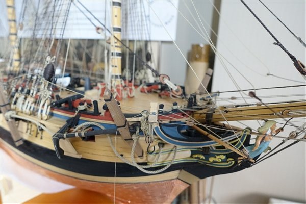
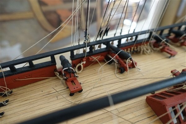
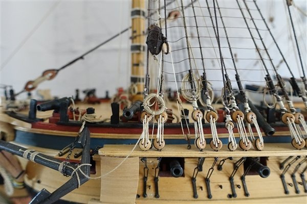
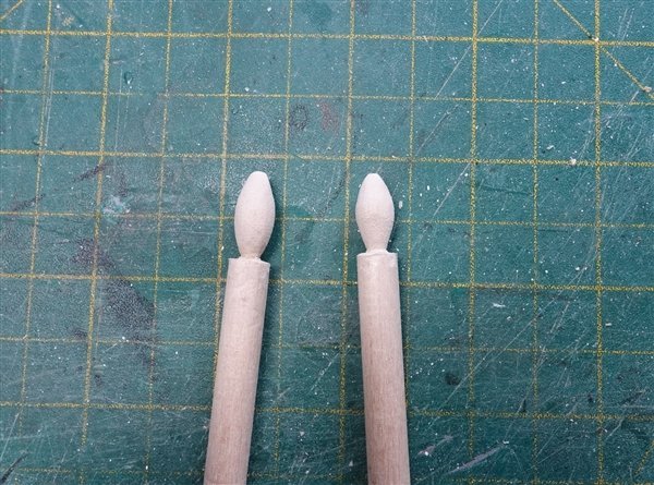
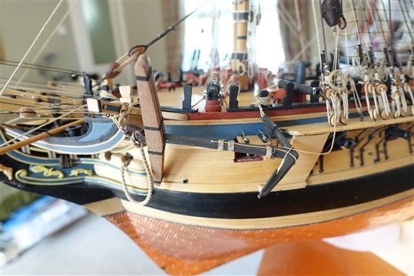
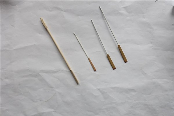
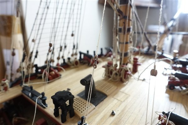
I sent for some longer Amati oars for the cutters but they are pretty ugly and much oversize. I attempted to whittle them down but gave up because they are made from limewood and I thought they wouldn’t stand much thinning down. In the end I made my own from 1mm brass rod and 4x1 tanganyika that I had. They are from the left, Amati, Vanguard Models, my versions for 18’ and 24’cutter. In the meantime my ropes arrived from Ben so I continued with a bit more rigging. Belaying the tacks proved to be less of a problem than anticipated although access under the gangway and around the guns is still tight. However I have run into a problem with the main sheets. The photo below illustrates the problem in that the standing part cuts across the barrel of the carronade. The eyebolt for the standing part is a little close to the gunport lid but moving it aft wouldn’t alter the fact that the rope would still cross the gun. I think this is a consequence of my moving the quarterdeck guns around to fit the open rails. If the gun was a little further forward and the eyebolt a little further aft, I might have got away with it. Too late to change now. My solution is to move the eyebolt forward of the gunport as shown in the photo below. Not ideal but... Thanks for the likes and for looking in. David
- 310 replies
-
- 10
-
-
- Diana
- Caldercraft
- (and 1 more)
-
Thanks Dave. I would like to make my own rope but I don't really have the room. David
- 310 replies
-
- 1
-
-
- Diana
- Caldercraft
- (and 1 more)
-
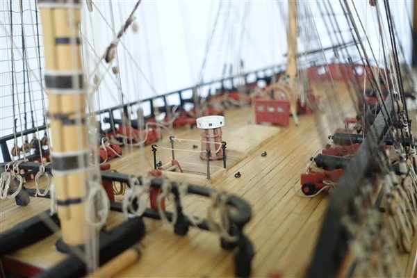
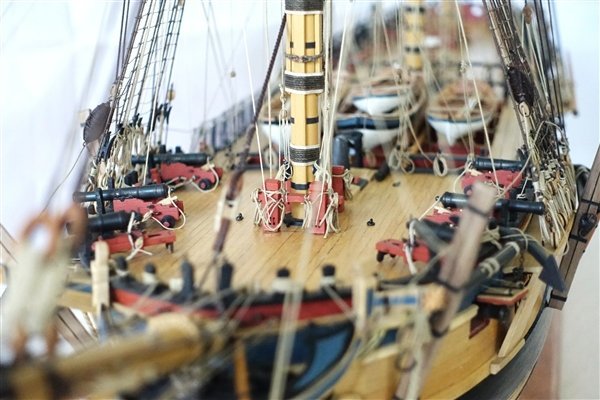
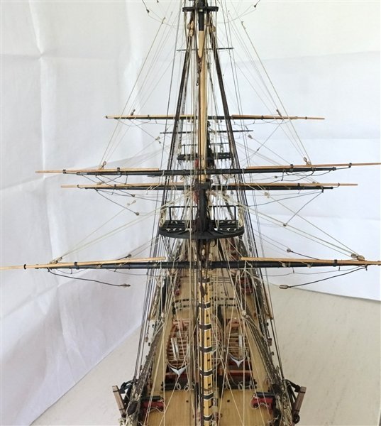
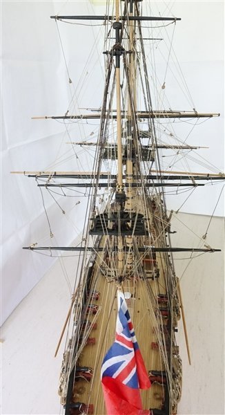
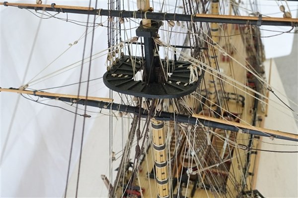
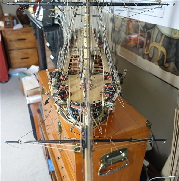
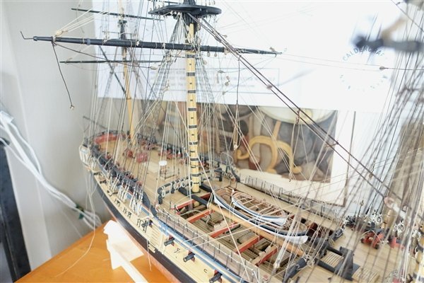
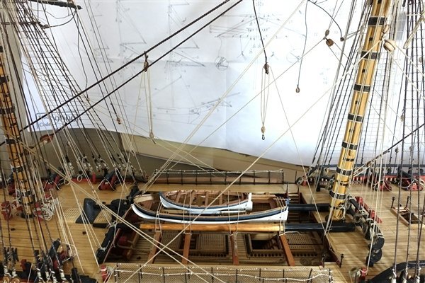
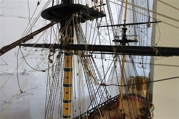
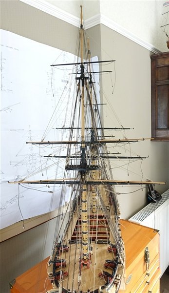
Your likes and comments are much appreciated as always. It’s a few weeks since I’ve updated the log due to commitments in the garden and I’ve had a week away in The Lakes, which has meant a slowdown in work on the ship. I’ve completed the main and mizen mast rigging. Getting clean runs of the rope becomes more of a challenge as I progress and there were a few accidents with already completed rigging along the way. The deck was beginning to look like a nest of snakes so I have also started adding hanks and trimming off the excess rope at the belay points. A few photos follow showing the current state of Diana. For the moment I propose to stop work on the rigging and continue with finishing the ship’s boats and deciding which ones to mount on the skid beams. But I’m in a bit of a dilemma. Should I mount the boats, in which case it could be difficult to tie off the sheets and tacks or add the sheets and tacks, in which case it may be awkward to mount the boats? Diana seems to be gobbling rope at a rate of knots, 😄 -I’m using far more than I anticipated so Ropes of Scale has received another order from me which hopefully will be sufficient to complete the rigging when the time comes to return to it. Thanks for looking in David
- 310 replies
-
- 8
-
-
- Diana
- Caldercraft
- (and 1 more)