


dunnock
-
Posts
530 -
Joined
-
Last visited
Content Type
Profiles
Forums
Gallery
Events
Everything posted by dunnock
-
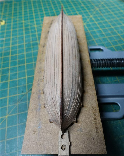
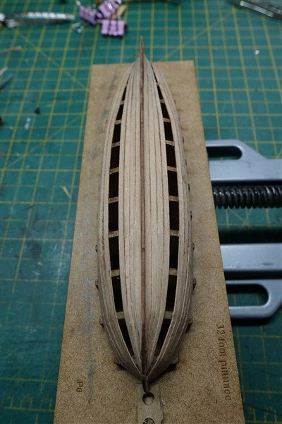
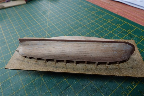
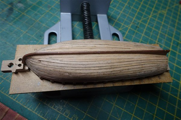
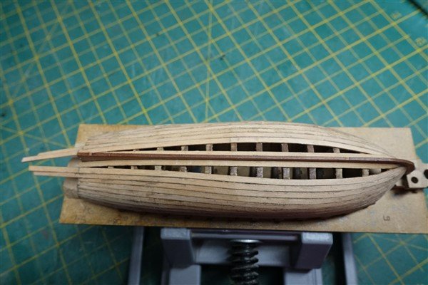
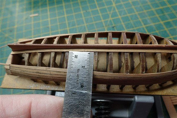
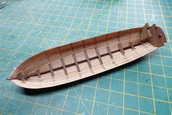
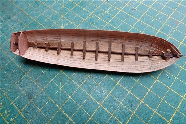
Thanks again for all the likes and comments. I have continued by planking the pinnace. After the first three strakes had been put in place, I had already broken a couple of planks and it wasn’t going well. Something wasn’t right and looking closely at the pictures on the original pdf of the instructions, I realised that the first strake didn’t start in the bow rabbet as I had thought, but just below. I removed and refixed the strakes and was able to continue the planking in a much better line. All planks were tapered at bow and stern and some required edge bending. I was able to use the broken planks for the final short spiled planks as there are only just sufficient supplied in the kit to complete the hull. In view of their delicate nature, a few spares would be nice. Nearly finished A bit more filler needed than I would have hoped. The launch was easier to plank but again it looks like the first plank doesn’t go to the rabbet and again I broke a couple. All planks except the first were tapered towards the bow and the last three towards the garboard were edge-bent. Again, I found that there are only just enough planks to complete the hull. I have none left over for the wales but can use some boxwood strip of similar thickness. Only 10 planks left and 12 required. I was able to recover the broken planks to finish off the hull but just as was fixing the last plank I slipped and put a hole in the bow. Luckily it wasn't a complete break and glued back easily. Sanding the hull is a delicate operation. With only 0.6mm to play with, some areas become worryingly thin. When the bulkheads are broken out, the shell is extremely vulnerable. I must try to use less glue on the bulkheads next time. Removing the excess needs a light touch using scapel and chisel and is helped by softening with a damp cloth. To try to give the hull a bit more stability I applied some diluted pva inside below where the gratings will sit and gave the outside a couple of coats of dilute matt varnish. David
- 310 replies
-
- 10
-

-
- Diana
- Caldercraft
- (and 1 more)
-
Extraordinary work David
-
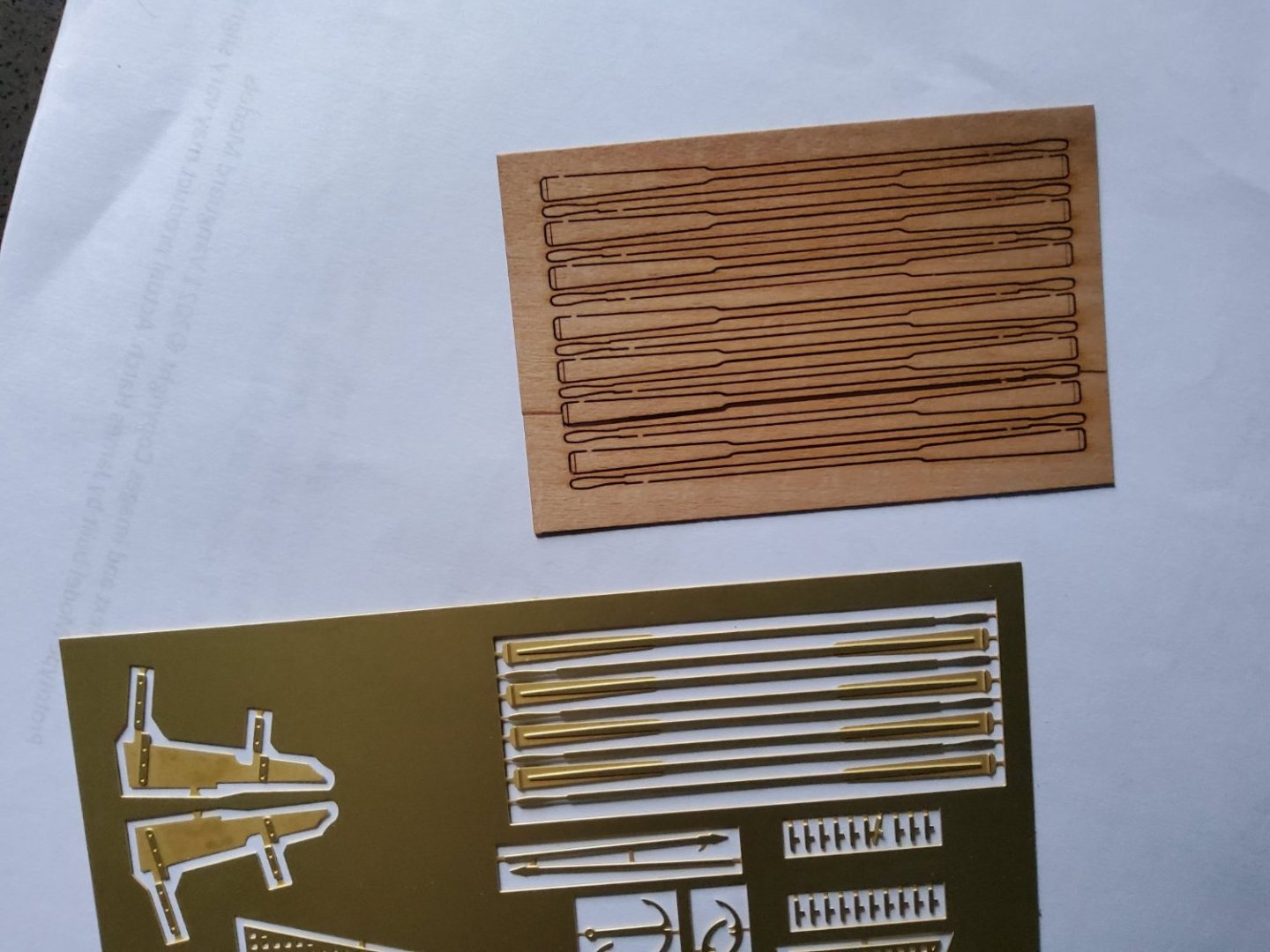
Thanks Andrew, Allan and Dave for your thoughts and comments regarding Diana's boats. Dave, the Vanguard boats come with both P/E brass and wood oars in 0.6mm pearwood. For the 32' pinnace they are 67mm long. The brass oars are 64mm. I'm not sure why they are different and the wooden oars different again from seemingly the same item offered separately on the Vanguard website. Hope this helps. David
- 310 replies
-
- 5
-
-
- Diana
- Caldercraft
- (and 1 more)
-
Beautiful work Jason
-
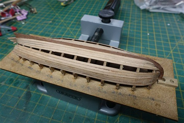
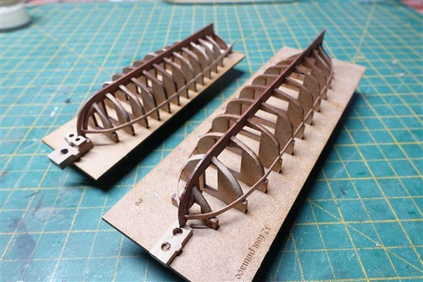
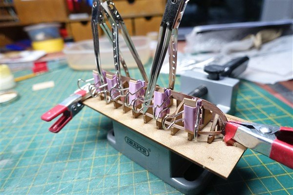
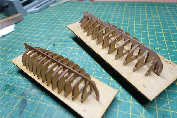
Thanks everyone for the likes and comments. As a change from fixing and rigging masts and Also while I’m waiting for further supplies of rope from Ropes of Scale, I am turning to making some of the ship’s boats. I started to make up one of the supplied boats in the kit but soon realised that they just wouldn’t do so as a sort of Christmas present to myself, I order a 32’ pinnace, 26’ launch, and 24 and 18’ cutter from Chris Watton. I have begun with the pinnace and launch, reasoning that the two larger boats might be the most straightforward. Well, if they are, I’m going to have fun with the other two. The bulkheads for the pinnace all slotted into the baseboard easily and without any sanding needed. The sternboard went on easily too. I added some extra support at the prow and the stern because both looked quite vulnerable. The launch however, required the slots in each bulkhead to be opened up a touch. Almost inevitably, when trying to fit the sternboard to the launch, the keel piece snapped. A drop of superglue was enough to fix it back in place and more support blocks at stem and stern will hopefully protect both. The forward and aft bulkheads were faired on each boat and the first planks have been fitted. David
- 310 replies
-
- 7
-
-
- Diana
- Caldercraft
- (and 1 more)
-
A lovely model Glenn. This and the other great little boats you have built have inspired me to make them my next project after my Diana is completed. David
-
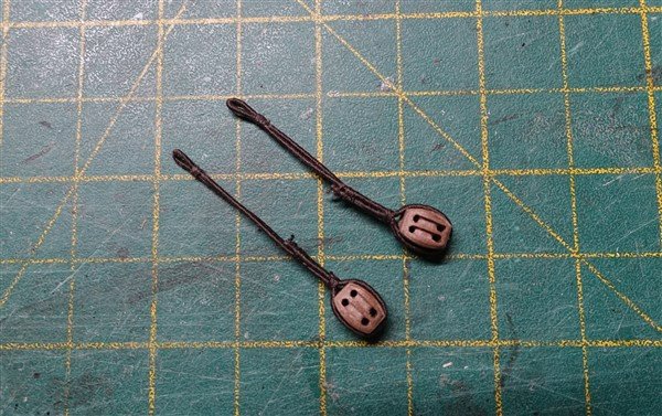
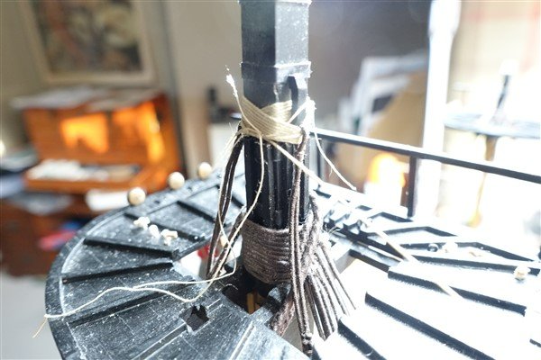
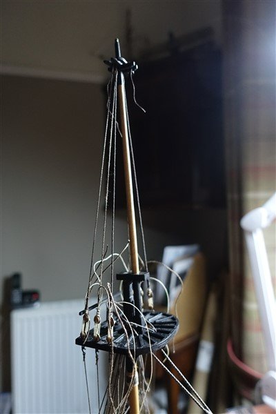
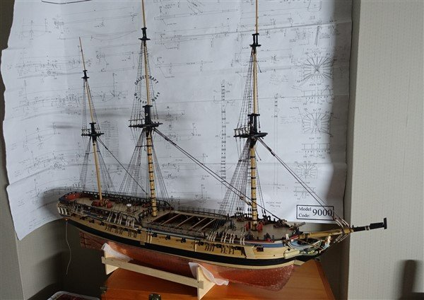
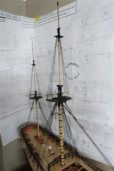
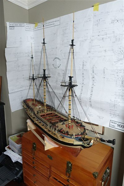
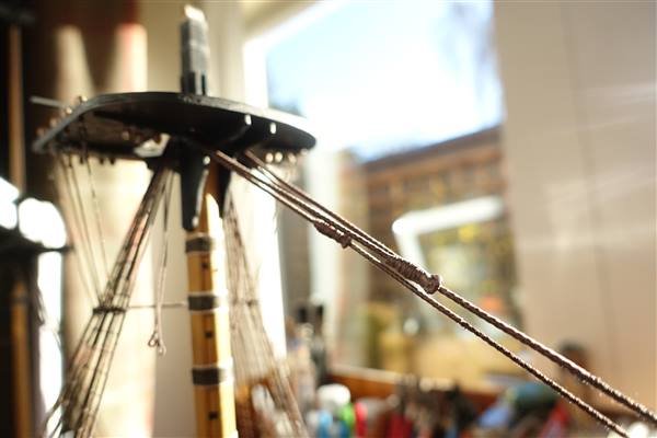
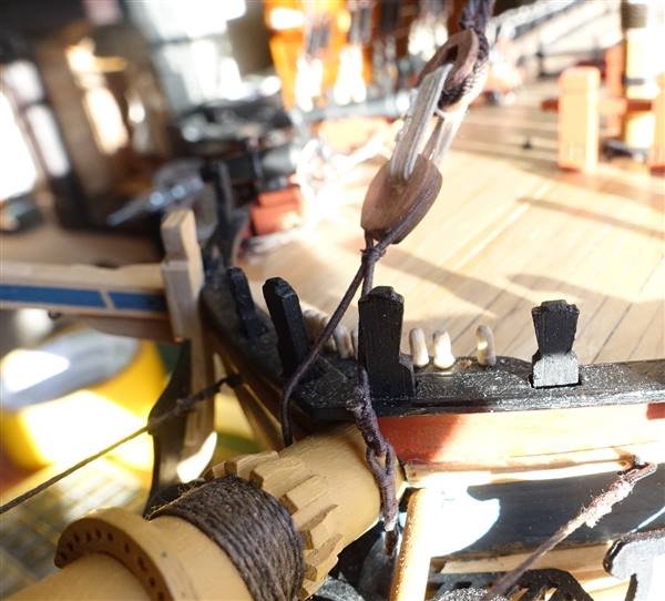
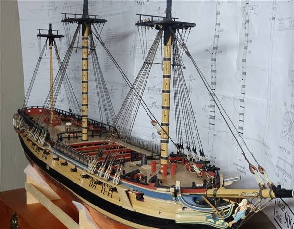
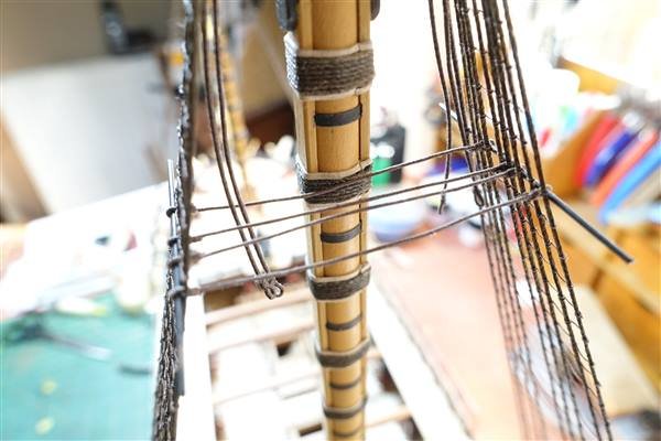
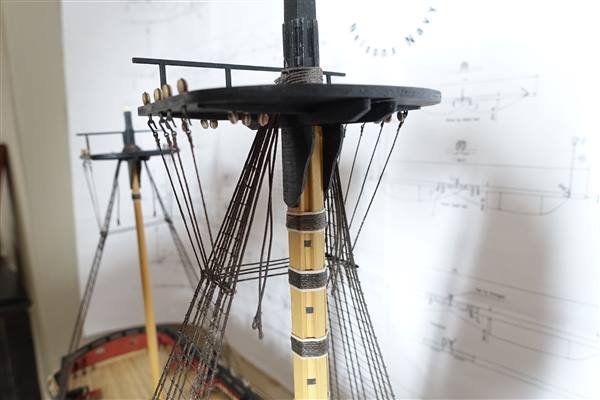
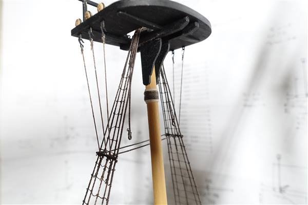
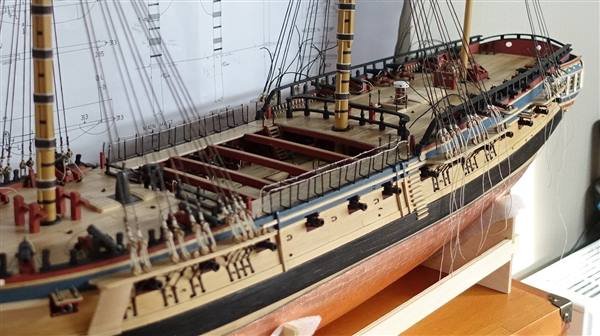
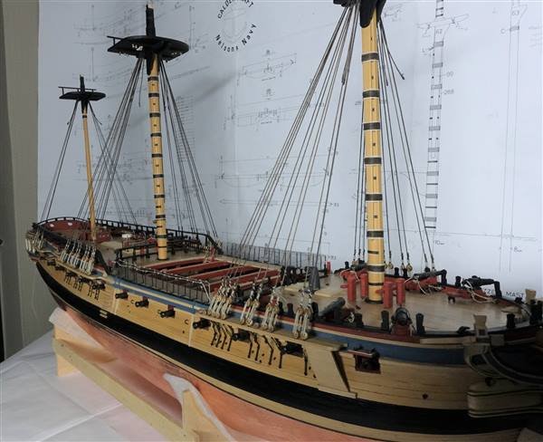
The lower caps and topmasts are complete. I’ve also made the topgallants and when mounted, the ship has become quite a handful to manoeuvre. The walnut lower caps supplied with two round holes are not correct. I thought about making the round hole into a square to fit the lower mast but decided it would be simpler to make them from scratch. All the caps were made from 5mm thick boxwood. I didn’t have a single sheet of this thickness so laminated together 1.5 and 3.5mm pieces. The mizzen cap is thinner and was sanded down to 4mm after completion. The holes were made by drilling a series of 1mm holes around the perimeter and then filing and sanding to fit. The corners are rounded. The only drawing Lee gives for positioning of eyebolts in caps for 1773 and later shows them in a position that ‘does not conform to the usual practice’. Lee says that they should be placed equidistant around the round hole. The dimensions for the topmasts were taken from AotS and made from ramin dowel. The instructions show the fids positioned midway through the square section of the mast. I should have checked before-hand but when it came to mounting the topmasts, it was obvious that the fid holes should be lower and about 1/3 up the heeling. It was an easy matter to fill and remake the holes in the correct position. The fore and main masts have cheek blocks fitted at the mast head which were cut out of 3mm boxwood section. The mast head and foot areas were painted in matt black and the mid-section stained with antique pine wood dye. Before fixing the topmasts in position, I thought that it might be easier to add the lower yard slings and jeers at this stage. The slings are made from served line with a thimble seized into the lower end and sit on a bolster over the cap. The required length was estimated using thread and the appropriate length served on the machine. An eye is seized in one end and the thimble seized in place such that the sling has a long and a short end. The long end is passed through the eye and seized to itself. The jeers are made from a 7mm double block in a double strop. The strop is seized throughout its length. Again, careful measurement is needed to obtain the correct length. An eyed is seized in the end of the strop and lashed to the masthead with 5 turns of rope. The lashings are held in place with a cleat I’m not sure how but despite measuring several times before cutting, I had made the lower foremast head 15mm too short. This became only too obvious when I tried to fit the fore topmast. An additional piece was tenoned onto the existing mast and the join filled and over painted. An ‘iron’ band made from black paper was added to the mast head just below the cap. I don’t think that this correction will be noticeable in the finished model. The first ropes to be added are the burton pendants made from 0.75 served rope. A thimble is seized in the end. The shrouds are 0.75mm dyed Amati rope and are set up in the same manner as the lower shrouds. The forward pair of shrouds on the fore and main topmasts have sister blocks tied in to take the top yard lifts. I couldn’t find any commercial versions so made them from 3mm boxwood section. I made them as small as I could but at 2mm by10mm long, I think that they still may be a little oversize. The deadeyes are set up with 12mm spacers made from 0.75mm diameter brass rod. Getting the lengths of the shrouds sit correctly with deadeyes at the same height proved to be a very frustrating exercise and most were reworked at least once. There are still some that are not quite right after three or four attempts, but I think they are as close as I can get without losing the will. The following shots show Diana in her present state. The topgallants are not fixed and in fact I have not glued any of the masts. They are all held in place by their own rigging. David
- 310 replies
-
- 8
-
-

-
- Diana
- Caldercraft
- (and 1 more)
-
Sorry that it's taken me a while to respond but thanks David and Andrew for your kind comments on the rigging and to everyone for the likes. I've made a bit more progress over the last few weeks on the topmast and topgallants and will be posting an update shortly. David
- 310 replies
-
- 2
-
-
- Diana
- Caldercraft
- (and 1 more)
-
Hi Oakheart, Going straight in to scratch building is impressive. I don't think that I have the skills (or understanding) to take this leap and I wish you good luck with your project. I noticed in some of your comments on Allanyed's log that you are struggling to source suitable wood for modelling in the UK. I have been using boxwood strip from Original Marquetry Home - Original Marquetry Ltd. I have also used pear and boxwood from Timberline Steamed pearwood guitar banding 800 x 6 x 2mm - Timberline - Exotic Hardwoods and Sundries. There was another supplier that I found the other day. I thought that I had added it to favourites but I'm struggling to find it again now. I'll let you know if I come across it again. David
-
A very nice colour scheme Glenn and the hull looks very smooth now.
-
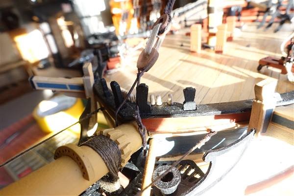
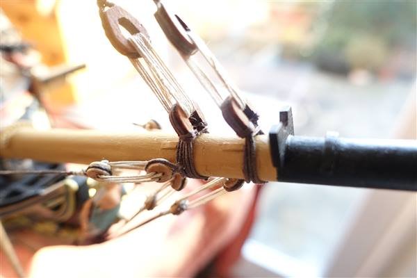
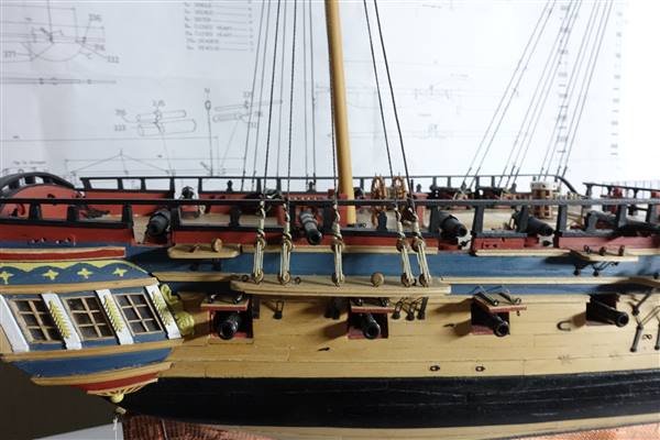
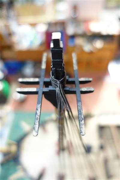
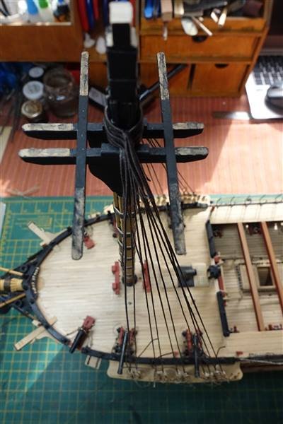
It’s been nearly a month since I last posted but work has continued with mast and yard making but the next logical task was to fit the lower mast stays. This meant fitting the bowsprit first. The bowsprit was made from 12mm ramin dowel and sized according to the dimensions in the AotS Diana rather than the Caldercraft plans. The maximum diameter worked out at 11mm. The taper begins at 120mm from the bow reducing the diameter to 6.4mm at the cap Gammoning cleats, saddles, bees etc were all fashioned from scratch using walnut section and sheet as required. The deadeyes and hearts were fitted off the ship. 5mm deadeyes were used for the forestays, bobstays and shrouds using served strops from 5mm line. The closed hearts provided in the kit were swapped out for some 10mm open hearts from Vanguard Models, again tied with 5mm served rope. The bowsprit was slotted through the bow and into the bowsprit step on the upper deck. The gammoning proved less tricky than I expected. Using 0.75 dyed line, a false splice was made around the bowsprit and passed forward on the bowsprit and aft in the hole, each wrap being kept tightly in place with a clip. 10 wraps filled the hole in the stem nicely and a further 10 frapping turns were taken to tighten up the wraps and finished off by seizing to an adjacent end. The mainstay collar is made from served 0.75mm line. It was very tricky to thread this through the head works and the hole in the stem. It might have been easier in hindsight to do this before the bowsprit was fixed and the gammoning in place. After a bit of fiddling with a large needle and tweezers it was completed. An eye is seized in each end and linked together. A 10mm closed heart is seized into the loop such that there is a short and long leg. The bobstays were made from 0.75mm served rope. Sufficient length is served to make a complete loop around its deadeye and through the hole in the stem. The unserved ends can then be joined using a false splice and a 5mm deadeye seized in the end. A seizing is added to the opposite end to hold it in the bobstay hole. Finally the bobstay is lashed to the appropriate deadeye on the bowsprit with a 5mm lanyard. Port and starboard shrouds are added using 0.75mm dyed rope. A 3mm hook is seized into the after end and a 5mm deadeye in the forward. The shroud is hooked into an eyebolt in the bow and the deadeye tied to the bowsprit with a 0.5mm lanyard. This completes the bowsprit. I bought some dark brown cable-laid ropes from Ropes of Scale for the main and fore stays but used standard Amati rope for the mizzen stay. The stays are all worked similarly at the mast end, being served for about 6 feet (30mm) below the level of the mouse. The stay is measured to the required length and the position of the mouse marked with a thread. Serving proceeds to the marker and then I wrapped some 5mm line around to form the basic mouse shape and fixed it with plenty of dilute pva. The serving line was then continued back and forth over the mouse until covered and the serving completed to the required length. An eye is seized into the upper end to butt against the mouse. The mizzen stay is made from 1.25mm rope. No cable-laid rope was available at this size so I used some Mantua rope. It is fixed to the main mast with 5mm deadeyes. The main stay was made from 1.8mm cable and the preventer stay from 1.35 cable. I attempted to worm these ropes but after several unsuccessful attempts, abandoned the idea and had to be satisfied with having a served section only. The preventer stay is fixed to a closed heart about 60mm above the deck on the fore mast using a 5mm lanyard The lanyard is given enough wraps around the two hearts to fill them and then the end tied to an adjacent end with a couple of seizings. The mainstay sits on top of the preventer stay to give the best line between the two. A closed heart is seized in the lower end and this is attached to the heart at the bowsprit with a lanyard of 5mm rope. The foremast stays are 1.6mm cable laid rope and the preventer stay 1.25mm standard rope. Again 10mm closed hearts are used. With the rigging of the lower masts now completed, I have reached a dilemma. Do I continue with the topmasts or attach the lower yards? I am concerned that fitting slings and jeers with the topmasts in position will be very awkward. The topmasts have been made, as have the lower yards but I’ll cover these at a later date. I think that I’m inclined towards fitting slings and jeers. Also adding another layer of masts will making manoeuvring the model more difficult and I’m anxious to keep things simple for as long as possible. This has been a longer post than I anticipated and I should have taken more pictures of intermediate stages than I did but if you are still with me, thank you for sticking with it. David
- 310 replies
-
- 9
-
-
- Diana
- Caldercraft
- (and 1 more)
-
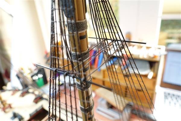
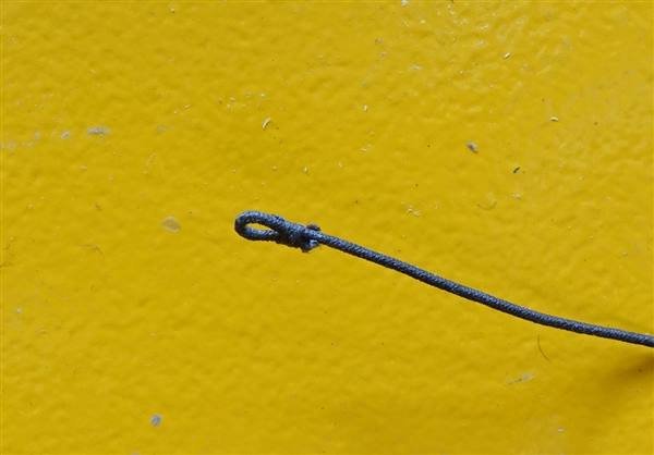
Thanks to all for the likes. Continuing with catharpins, futtock shrouds and shroud cleats. I made the first catharpin for the main mast, checked it for length on the model and thought I would make a simple jig using two pins in a piece of wood so that they would all be the same length. However when it came to fitting the other three to the futtock stave, I realised that my cunning plan didn’t allow for the increasing distance moving aft between port and starboard shrouds. Luckily, I hadn’t cut the tailings off, so I could just cut one of the siezings from each catharpin and size them independently on the model. To make sure there was no mix up, I numbered each one before This process was repeated for fore and mizzen masts. I hoped that once the futtock shrouds were fitted any slight slackness would disappear. I wasn’t keen on Caldercraft’s instructions for making the futtock shrouds, using rope for deadeye stops and then leading it down to tie off at the stave. I had some 3mm strops left over from Swan so used these. The shrouds were made from 0.75mm stained rope. This is a little on the heavy side but still looks good to my eye. A hook was seized into the upper end of the shroud, clipped into the eye of the strop and led down to the futtock stave. The shroud is wrapped around the stave and then tied to the lower shroud with three siezings. The mizzen futtock shrouds were set up in the same way but using 0.5mm stained rope. The ratlines should be added next, but I will leave that until the topmast shrouds are set up so that any variations in their tension do not distort the ratlines. The shroud cleats were tied on by first clove-hitching a length of thread onto each end and fixing with a dab of dilute pva. Each cleat was then tied on to the shroud with overhand knots and another dab of pva. Making sure that the clove hitch is centralised helps with positioning the cleat on the shroud. Based on the belaying plan in the AotS, cleats are tied to every shroud on the foremast and the last two shrouds on the mizzen. I'm working on the lower stays and collars now Thanks for looking in David
- 310 replies
-
- 10
-
-
- Diana
- Caldercraft
- (and 1 more)
-
Love the binnacle David and the detail of lamp and two compasses just excellent
-
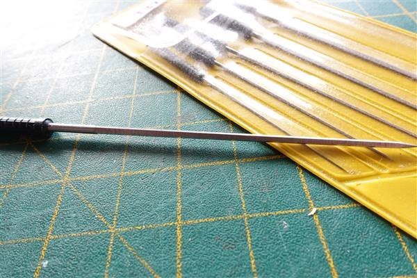
Thanks for your nice comment on the ratlines Jason. Your point on the tool used (pun intended) prompted me to look them up. This link brings up a five sided version and are listed as watchmaker's cutting broaches. I also have a set of round smoothing broaches that are useful for cleaning out holes in blocks. https://www.eternaltools.com/watchmakers-cutting-broaches-set-06mm-2mm I'm sure you'll be able to find a set in the US I think a bradawl is, to use a technical description, a 'pointing thing with a handle' to make a small pilot hole before drilling. David
- 310 replies
-
- 4
-
-
- Diana
- Caldercraft
- (and 1 more)
-
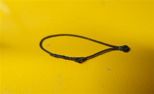
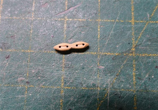
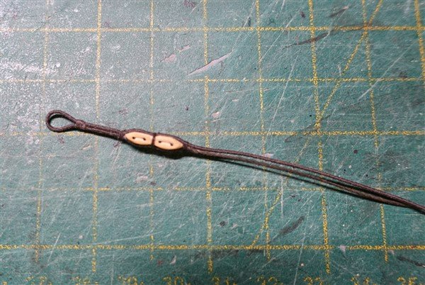
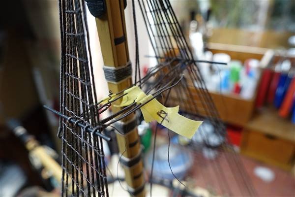
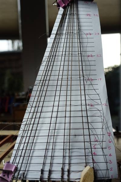
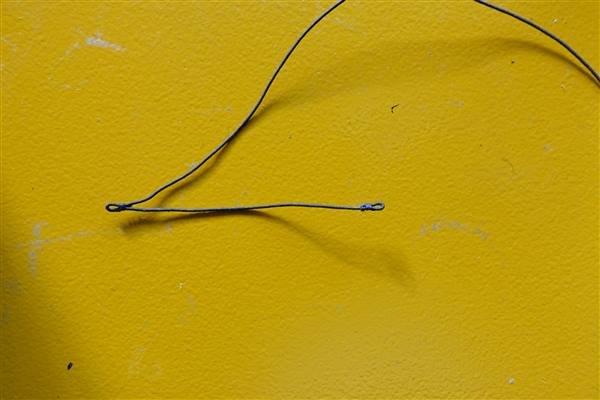
Hi all and thanks again for all the likes. I have been working on the ratlines for the past couple of weeks and to break up this process, I’ve been finishing off the topmasts and begun rigging the bowsprit, which will be the subject of a separate post. My daughter, being a lot cleverer than I, provided me with a PDF file of lines drawn at 5.8mm which I printed off and cut to shape to use as a guide to keep everything straight. Lees says that at the time Diana was built, the first and last 6 ratlines did not tie to the first and last shroud on each mast. To remind me, I marked these on the paper guidelines. The ratlines are worked in 0.25 Gutterman dark brown cotton thread in the usual way with half hitches on the first and last shroud and clove hitches for the rest. To begin, I tied the first run and then every 5th and then filled in. Once you get going there’s a rhythm to it but I found that pinching such a fine line makes finger and thumb ache so I could only keep going for an hour at a time. The first set on the foremast and some of these will need retying. All finished now and I have started work on catharpins and shroud cleats. I liked Ray’s description of making the catharpins in his Diana blog from 2014 https://modelshipworld.com/topic/707-hms-diana-by-ray-finished-caldercraftjotika-a-38-gun-heavy-frigate-1794/page/13/ which I shall copy with grateful thanks. 0.5mm thread is stained and then served with Gutterman thread The eyes are seized with 5 wraps of the same Gutterman cotton thread and tested for fit on 1mm blackened brass rod as futtock staves. The shroud cleats I will be using are from Chris Watton and much nicer than the white metal ones in the kit That's all for now David

- 310 replies
-
- 4
-
-
- Diana
- Caldercraft
- (and 1 more)
-
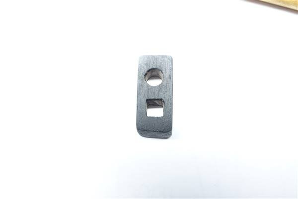
Dave, I forgot to mention that I finish off by using one of these square section cutters. I'm sorry, I've forgotten what they are called but they are very useful for enlarging drilled holes. Hope this helps David
- 310 replies
-
- 1
-
-
- Diana
- Caldercraft
- (and 1 more)
-
Hi Dave, It wasn't too hard. I just drilled a 2mm hole from each side using a pin vice and then gradually squared them off, again from each side, with a fine square section file. I've not tested them yet with the fid so it might all go wrong yet... David
- 310 replies
-
- 1
-
-
- Diana
- Caldercraft
- (and 1 more)
-
That's a very clever solution Jason and beautifully done David
-
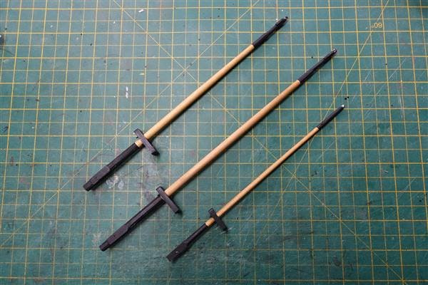
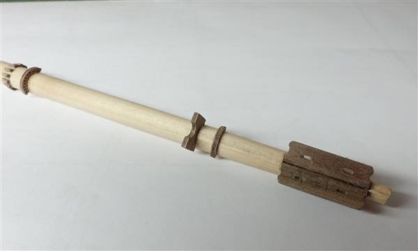
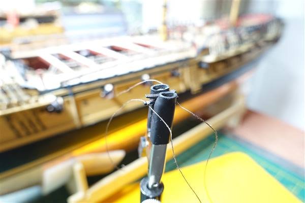
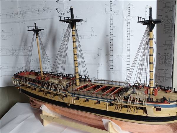
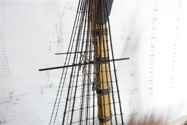
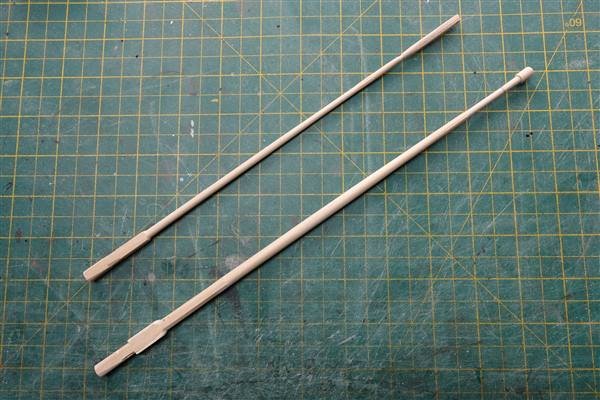
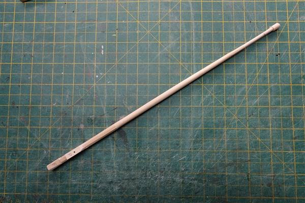
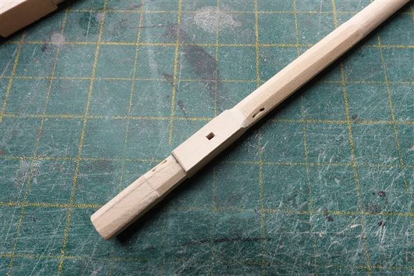
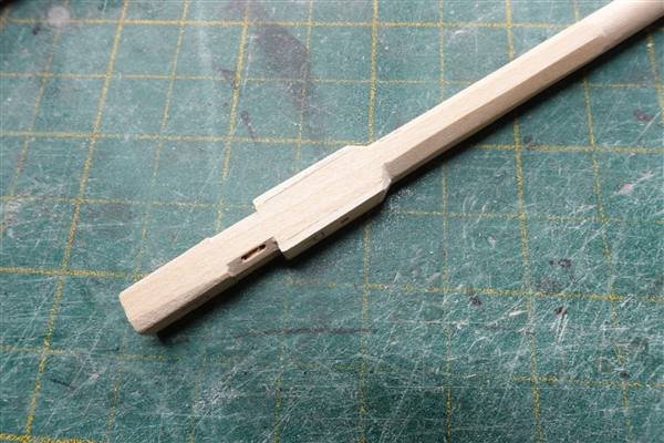
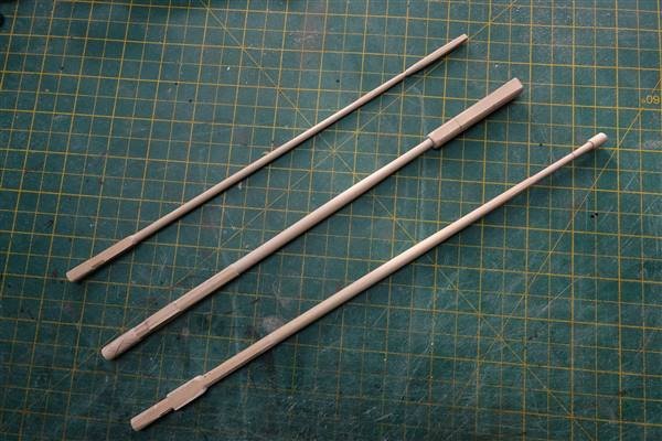
24/10/2022 Hi everyone and thanks for the likes. I’ve made some progress on the topmasts (and none on the ratlines). I’ve used the dimensions in AotS Diana and cross-referenced with Lees for tapers and diameters. The main and mizzen topmasts are almost completed with some details still to add and then trimming off the waste wood. I’m now on with the fore topmast. I planned to make them in order of size but owing to a mistake on the foremast it suddenly turned into a mizzen mast! I have puzzled over the heeling of the main and fore topmasts which in Lees are shown as being of larger square section all round than the octagonal section of the mast but only larger athwartships in the AotS and the Caldercraft plans. I have followed the AotS but I am thinking to add further pieces fore and aft to give a more balanced appearance. Heel and block from the starboard side and from forward. If anyone has a more definitive view on how it should look, I would be glad of some advice. All three topmasts. The lower sections of the fore topmast (pictured in the centre) are finished, the hounds and upper sections are to complete and details to add

- 310 replies
-
- 7
-
-
- Diana
- Caldercraft
- (and 1 more)
-
Thanks again for the likes and comments. Just a short photo update to show the completed lower shrouds. Theoretically all the lower shrouds should be in 1mm rope but I wanted to show a contrast between the mizzen shrouds and the fore and main so I used 0.75mm rope coloured as before with Jacobean Oak wood stain. No real problems were encountered except that I had to re-tie a couple of the seizings because I had cut the tailings a little too close, oh and despite checking the position of the mizzen shrouds several times, I still tied a lower shroud where the topmast backstay should be. Luckily it was a simple matter to put it right. Foremast completed, main and mizzen to set The ratlines are the obvious next step but I will break up this laborious task by making the topmasts. David
- 310 replies
-
- 8
-
-
- Diana
- Caldercraft
- (and 1 more)
-
I've been away so I'm a bit late to add my congratulations on the completion of your wonderful model of HMS Sphinx. I have closely followed your log and like Pegausus before it, it has been an inspiration and an encouragement in my model shipbuilding. I will be greatly looking forward to your next masterpiece. David
- 857 replies
-
- 5
-

-
-
- Sphinx
- Vanguard Models
- (and 1 more)
-
Thanks very much Jason, I did get a few pings last night! It's good to see you back as your superb build of HMS Jason has been a big inspiration to me. Looking forward to following you continuing with your build as you return to the shipyard. In the meantime I will continue to flounder on in my own way. David
- 310 replies
-
- 2
-
-
- Diana
- Caldercraft
- (and 1 more)
-
Thanks Jeff, your comments are much appreciated. Looking at the photo of the forward deadeyes and shrouds, it looks a bit washed out. I've completed the main mast and am starting on the mizzen shrouds and will take some better pics when they are completed. David
- 310 replies
-
- 2
-
-
- Diana
- Caldercraft
- (and 1 more)
-
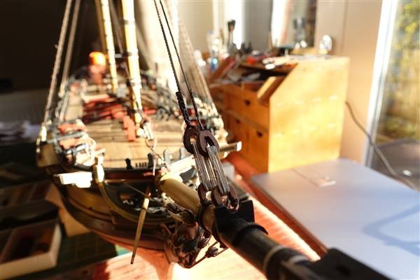
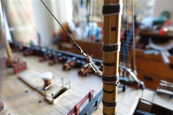
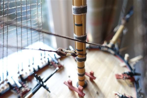
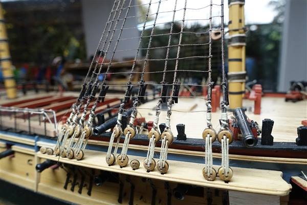
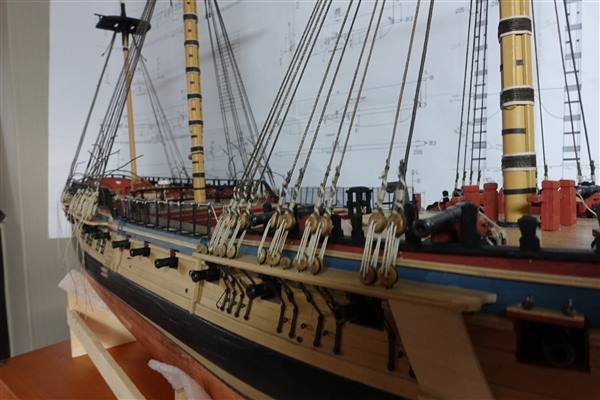
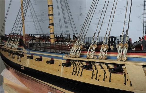
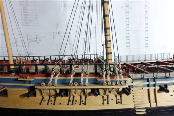
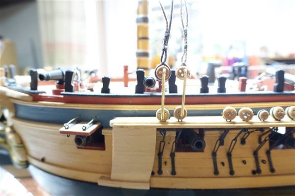
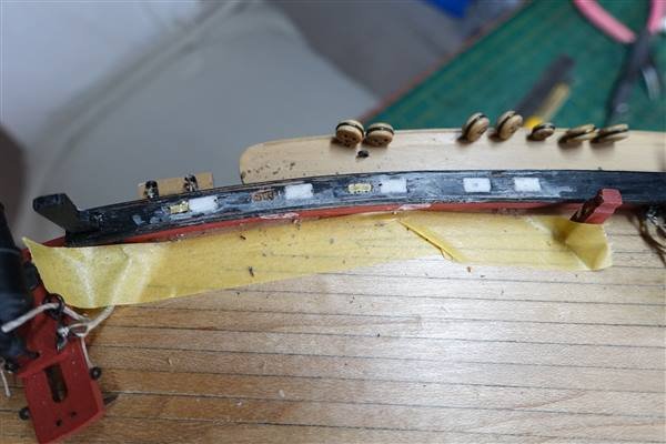
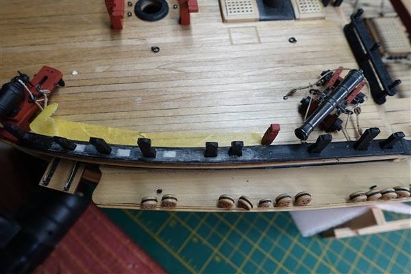
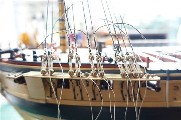
Thanks everyone for the likes and comments With the masts in place it’s time to start rigging… All the standing rigging will be made from hemp or cotton rope coloured with Jacobean Oak wood stain, except for certain stays and ropes where I have bought dark brown cable-laid rope from ‘Ropes of Scale’. Beginning with the foremast, the first to be added are the tackle pendants. These are fully served with dark brown Gutterman cotton thread. The kit instructions suggest that a pair are fitted to each side of the fore and main mast and singles to the mizzen but Lees says ships below 50 guns had only one each side. I found it easiest to make these tackles in pairs so for the fore and main masts, that is what I have gone with. The shrouds are 1mm rope which is nearest to the calculated 0.96mm. They are laid in pairs starting with the foremost starboard pair. According to Lees, the foremost shroud is fully served and the rest served to 8ft below the centre of the pair equating to 38mm. I used 40mm for simplicity. This is slightly different from the kit instructions, which suggests that the serving comes further down the second and subsequent shrouds to about the level of the futtock stave. The first snag that I found was that despite thinking I had lined up the guns to avoid shooting out the shrouds – they weren’t and needed moving by 4 or 5mm. This meant some reworking along the capping rail and moving the timberheads to get better alignment of the gunports was required. The second problem was that as when rigging HMS Fly, I found that preventing the deadeye from rotating while keeping the shroud tight and tying the throat seizing took several attempts, particularly on the first shroud which is much stiffer because of the serving. Once the throat seizing is secure then tying the remaining two seizings is made simpler using my ‘quad hands’. The fore top wasn’t as firmly fixed as I’d thought and I managed to knock it off when laying the second pair of shrouds. However it was now much easier to tighten the seizing around the head of the mast and I wish that I’d left them all off until shrouds and stays were fitted. The lanyards are 0.5mm rope and threaded starting from the right-hand hole in the deadeye. Lees's diagram only shows shrouds and deadeyes from inboard. To help with threading, I made my own drawing looking from outboard and hope that I have them all in the right orientation. This last shot gave me a bit of a fright and made me go back and check but it must be the camera angle that makes the chains and deadeyes look out of line because they are ok on the ship The lanyards are not finally tied off and looking at the tensions in the shrouds, I think that one or two will need to be reset. I plan to do them all at the same time when shrouds are in place for all three masts. Thanks for looking in David
- 310 replies
-
- 8
-
-
- Diana
- Caldercraft
- (and 1 more)
-
Thanks Allan for your kind compliments. Lees 'Masting and Rigging of English Ships of War' is a great source of information although sometimes difficult to interpret, at least for me. As to your question, cartridge paper is just a high quality heavy paper about 250g/m2. I think. A lot of card stock seems to delaminate easily when you cut it or fold it, whereas cartridge paper is just one layer. It's so named because traditionally it was used to make paper cartridges. David
- 310 replies
-
- 3
-
-
- Diana
- Caldercraft
- (and 1 more)
