


dunnock
-
Posts
532 -
Joined
-
Last visited
Content Type
Profiles
Forums
Gallery
Events
Everything posted by dunnock
-
Thanks Jason, and thanks again for posting your method for clinker planking. David
- 310 replies
-
- 1
-

-
- Diana
- Caldercraft
- (and 1 more)
-
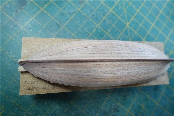
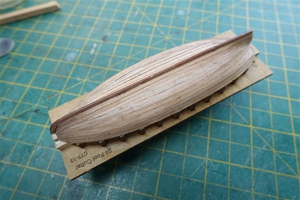
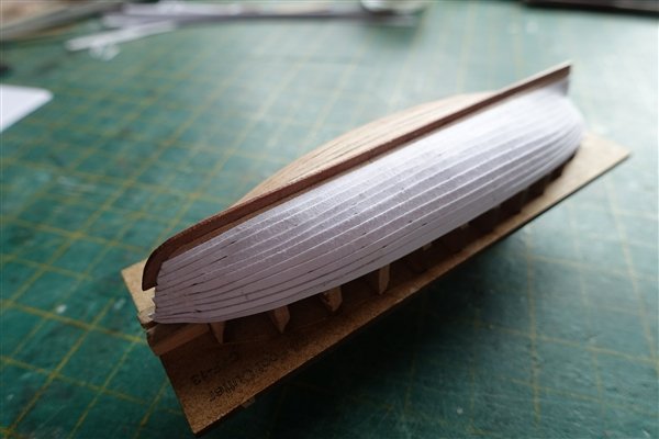
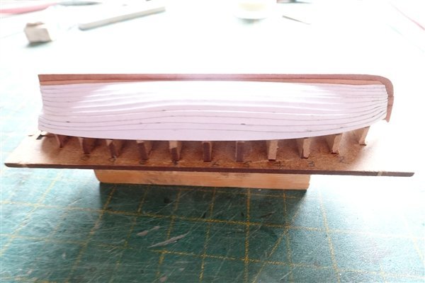
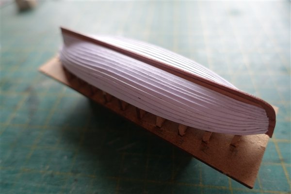
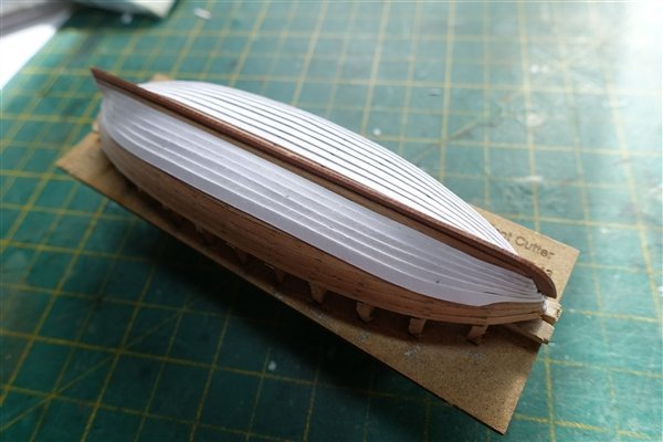
Thanks everyone for looking in and for all the encouragement you are giving me. Planking with pear strips is completed and I’m quite pleased with the result. I scraped the hull down and followed with a light sand which gave me a decent surface to continue with the second layer of clinker planking. My thanks to Jason (Beef Wellington) and the detailed description he gave in his HMS Jason log. Without it, I think that I would have been struggling to get as good a result as I have. https://modelshipworld.com/topic/7219-hms-jason-by-beef-wellington-caldercraft-164-artois-class-frigate-modified-from-hms-diana-1794/page/23/ The hull is marked out at each bulkhead using tick strips. I first tried a couple of strips of heavy paper (Conqueror) but it was too thin to provide a noticeable edge between planks. I stripped them off and began again with thin card (about 0.3mm). The angle of light and close focus shows that things could have been better but the first side generally went OK and the strakes look quite evenly spaced to my eye. I understand that the strakes at bow and stern do not overlap so I tried to keep to this pattern as closely as possible. The port side proved a little more troublesome. After 6 strakes I realised that the bow section was going out of line so removed the last three strakes and tried to correct it. This worked to some extent but when it came to the final strake, a fair bit of shaping was required. Although the strakes look to line up at the bow. I think now that the first strake runs a little to high at the bow and it’s this that has thrown things out. To consolidate the outer layer I have given the hull a couple of coats of dilute matt varnish. The next stage; removing the hull from the building board and breaking out the bulkheads is always the most nerve-wracking. David


- 310 replies
-
- 12
-
-
- Diana
- Caldercraft
- (and 1 more)
-
I used shellac on the decking and had no problems with bleeding.
-
Hi Dave, Just catching up on your log. It may be that with better wood you'll not have problems with a marker pen but thought I'd add my ten penn'orth. I've used Pigma Brush pens. It's easy to run the fine tip down the edge of the plank and not had any problems with bleeding. David
-
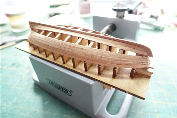
Thanks to all for the likes and for continuing to look in. A little more sanding was require to achieve a fair run before I started planking. Two planks each side fitted and I noticed that bulkhead 11 wasn’t seated correctly in the keel so they had to come off again. Unfortunately as I was trying to correct one mistake I made another and the transom broke away. I was able to CA the transom back, temporarily reinforced with strips of boxwood either side until there were sufficient planks in place to hold it firmly. After these trials, planking has gone quite well. I have used a dab of CA at the prow and then sparingly applied PVA on the edges of each plank. I also brushed dilute PVA into the joints.. I applied PVA to BH11 and the transom and only to the other bulkheads where necessary to maintain the line. Three more strips each side should complete. David
- 310 replies
-
- 10
-
-
- Diana
- Caldercraft
- (and 1 more)
-
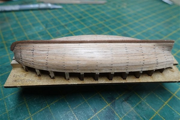
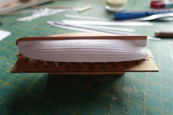
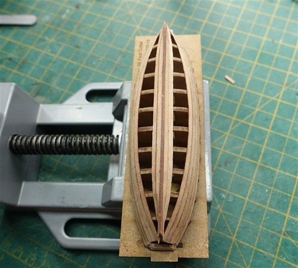
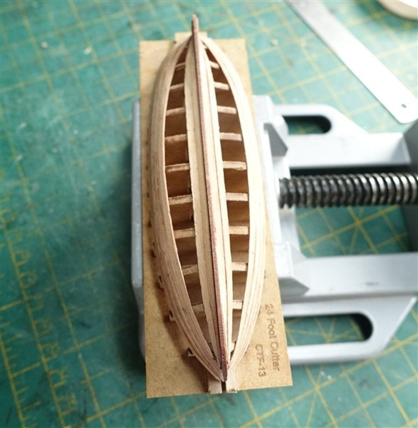
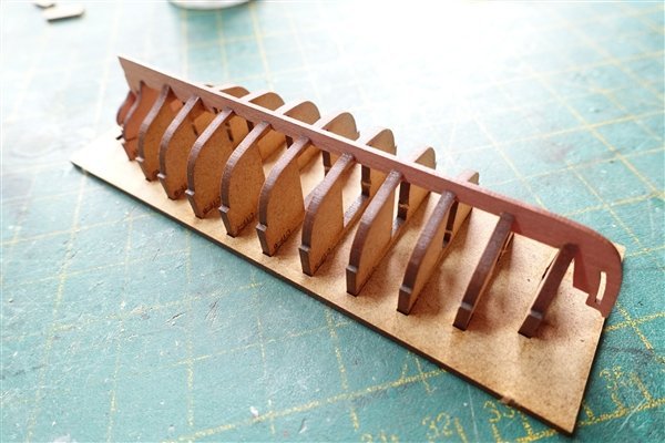
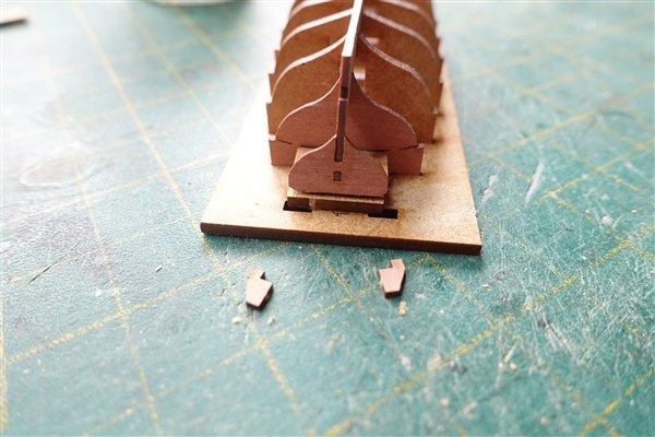
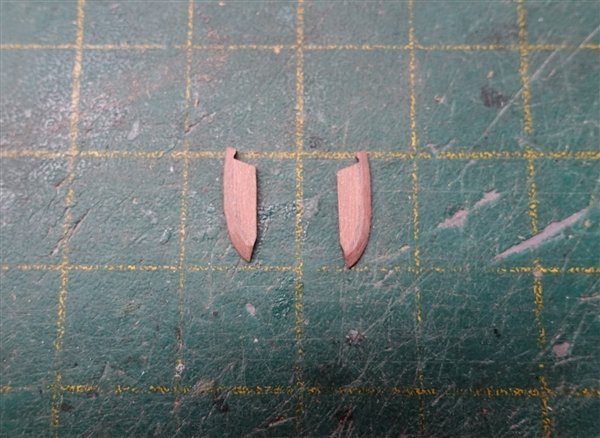
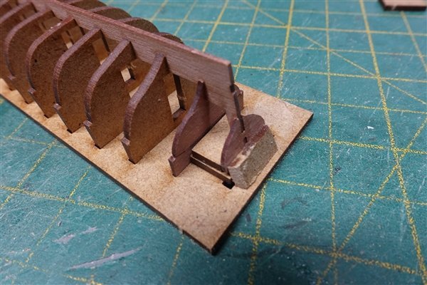
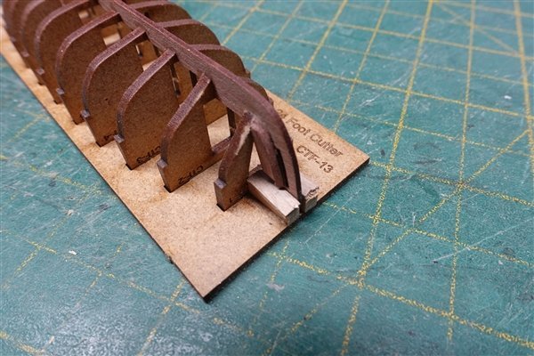
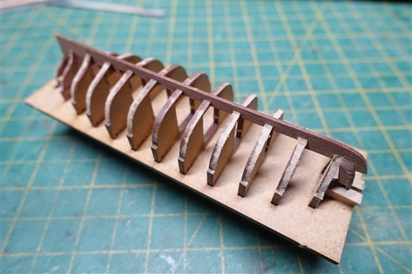
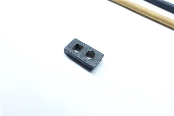
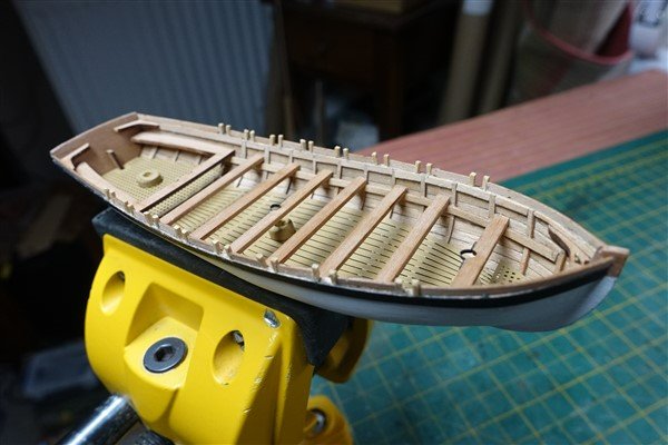
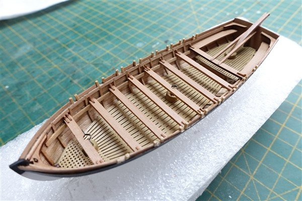
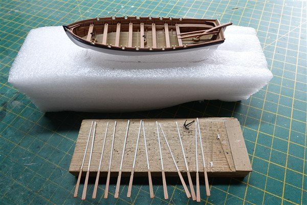
Thanks for all the likes A change of plan. On Monday I had a procedure to fix my damaged Achilles tendon which means I cannot put any weight on my left leg for the next 10 days. This makes it impossible to work on the main ship so I have gone back to the ship’s boats to start work on Vanguard Models’ 24 foot cutter. Cutters were normally clinker-built and I will try to replicate this by planking first with the pear provided and then apply a second layer of card planks in the manner of Beef Wellington as mentioned in a post above. The main mdf bulkheads fitted easily into the provided building board but the final two pearwood parts required a little fettling. Unfortunately the tabs on the transom piece broke off during sanding but the slot and square hole provide enough location to be able to secure it at the correct angle. The bow filler pieces were roughly shaped before gluing to the keel. From building the pinnace and launch, I know how vulnerable the stem and stern are during fairing so I added some reinforcement using bits of mdf taken from the centres of the bulkheads. Despite this I have managed to ping off the stem when checking how my fairing was going. I have recovered the broken piece and I am hoping that I can complete planking without it and then glue it back afterwards. I think I have faired the bulkheads enough using scrap wood to check the run but will give a final check with the pearwood planking. Thanks for looking in. David

- 310 replies
-
- 7
-
-
- Diana
- Caldercraft
- (and 1 more)
-
Thanks for your kind comments Dave and no problem about asking questions. I don't have an airbrush system so it's all hand painted. I don't use any special methods either- basicially I just slap it on and hope for the best. The black is Tamiya XF-1. I apply a coat and when dry, sand it back with 600 grit wet/dry. I usually apply 3 or 4 coats. The slight sheen is just how it comes out. When using other acrylics like Admiralty Paints or Humbrol, I usually dilute them quite heavily because I find that they are too thick to apply straight out of the bottle. The problem I find with Tamiya paints is that they dry too quickly and it's quite difficult to apply a consistent coating. I haven't tried adding a retarder. I think that the next model I build I will try Valejo paints. David
- 310 replies
-
- 3
-
-
- Diana
- Caldercraft
- (and 1 more)
-
Cutting the rabbet is well worth the effort even if, like me you don't get the engles completely right. Those chisels look nice Dave. Where did you buy them? David
-
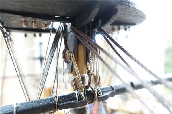
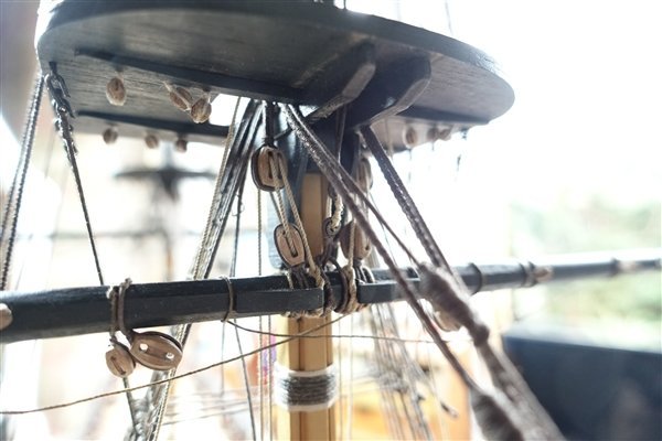
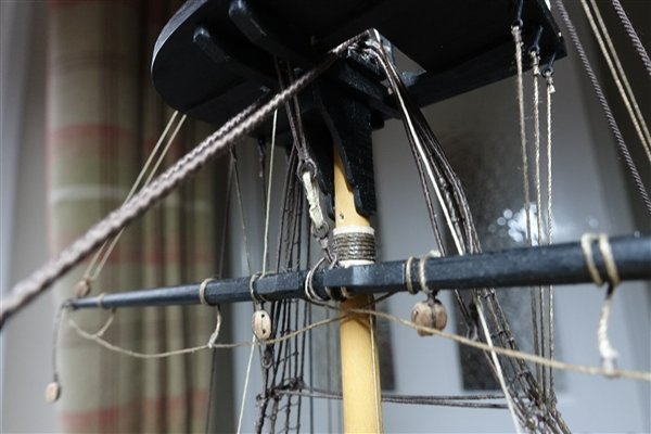
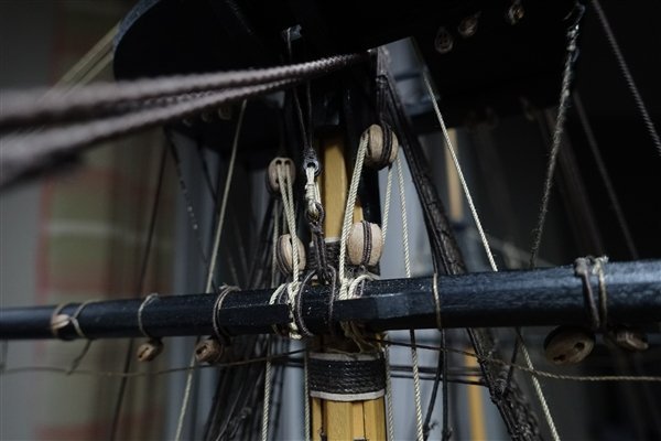
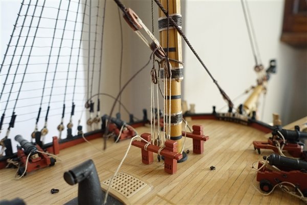
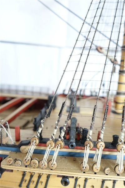
Thanks everyone for all the likes and comments The Lower Yards. I began with the crossjack yard and worked forward. I used Steele’s tables to calculate the appropriate size of rope and referred to AotS, Lees and Petersson for the run of the ropes. The crossjack is pinned and glued to the mast with CA for ease of working. The truss pendant is 0.35 rope spliced around the yard on the starboard side of the mast. It leads through a thimble spliced to the yard on the port side and ends in a long tackle block. The fall is 0.25mm and a single 3mm block is hooked to an eyebolt on the deck and the business end tied of to a cleat on the mast. The slings are lashed together with 0.25mm rope wound through each thimble as many times as would comfortably fit and then frapped around the front of the wraps. It is too fiddly to tie off each end with a seizing so they are tied off with a half hitch and fixed with dilute pva. The lifts are next. A single 3mm block is tied to an eyebolt on the cap. The running part is tied to the block at the cap runs through the block on the yard, back up to to the block at the cap and is tied off at the foremost pin on the after belay rack. Main and fore courses have a truss pendants (0.6mm) each side of the yard which are spliced on to the yard. The jeers (0.7mm rope) are also threaded up before the yard is lifted into place, pinned and fixed with CA. The lifts (0.6mm) are spliced to the yard arm and lead up through long tackle blocks on the mast cap, the small block on the yard arm and back to the long block. They are tied off to the timberheads on quarterdeck and forecastle. I had missed the timberheads on the forecastle because they didn’t appear on Caldercraft’s deck plans. Unfotunately I couldn’t position them as shown in the AotS belay plan because a 9 pounder is in the way. They were fixed slightly aft of where they are indicated but I think the run of the lifts is still fine. I am moving on to rigging the topmast yards at this stage leaving the further rigging of the lower yards till later.

- 310 replies
-
- 8
-
-

-
- Diana
- Caldercraft
- (and 1 more)
-
Lacking room to house a model the size of Indefatigable, I'm going to have to live it vicariously. I'm looking forward to following your build BE along with the other logs already begun. David
- 648 replies
-
- 6
-
-
- Indefatigable
- Vanguard Models
- (and 1 more)
-
Thanks Allen. I have both books that you reference and will have a go at clinkering the cutters when I get to them, leaning heavily on Beef Wellington's excellent description in his build of Jason.
-
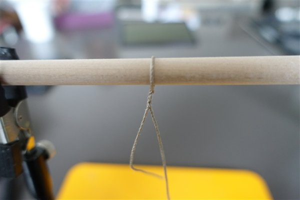
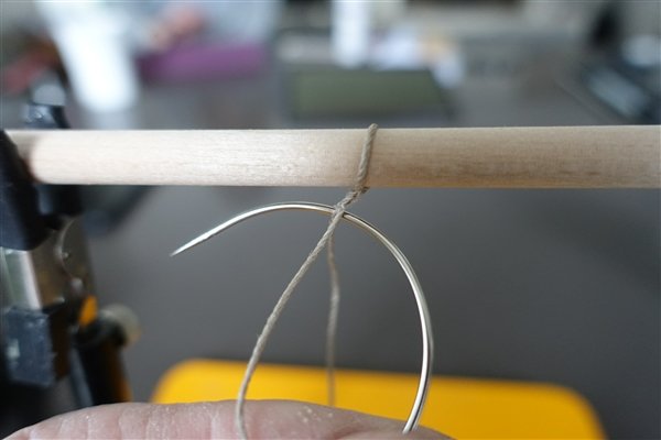
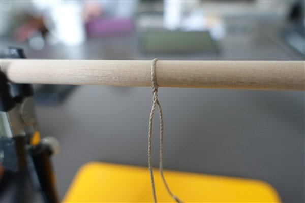
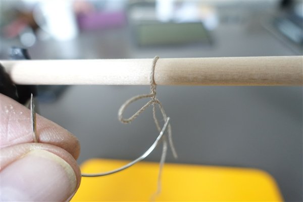
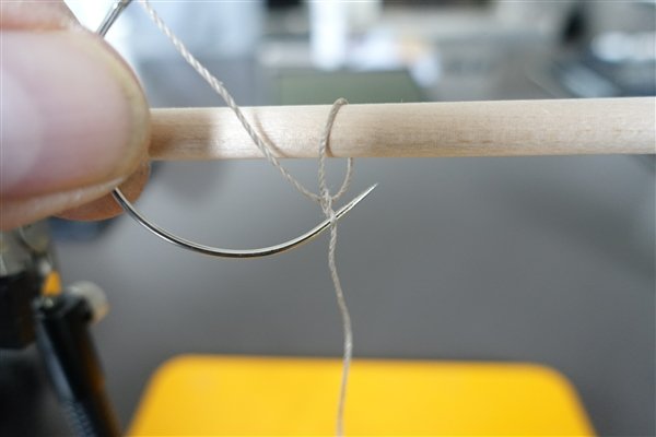
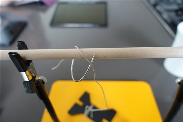
Thanks Ross and Andrew for your kind comments It's quite simple using a needle to thread the line back and forth through itself two or three times. The following photos should make it clear. To make it easier to see and photograph, I have used 1mm thread and a curved needle but it works with any size of thread and straight needle. It's best here to tighten up the loop around the yard or whatever else you are making the eye-splice for. A third pass through is ideal but not mandatory! The finished splice Secure it off with a dab of dilute pva. Have fun David
- 310 replies
-
- 7
-
-

-
- Diana
- Caldercraft
- (and 1 more)
-
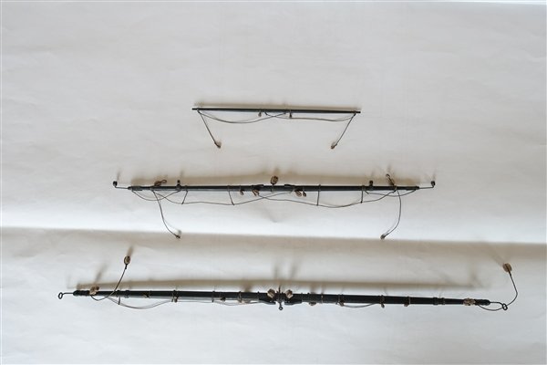
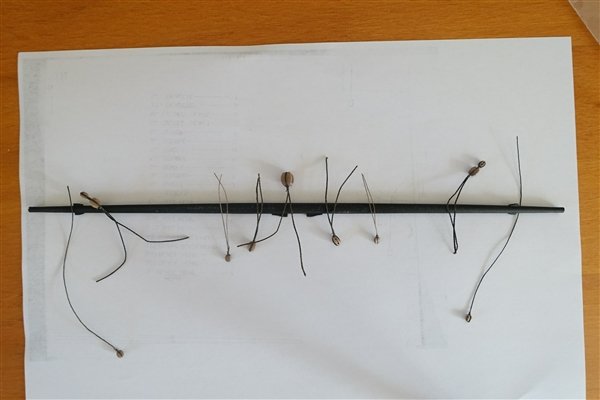
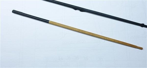
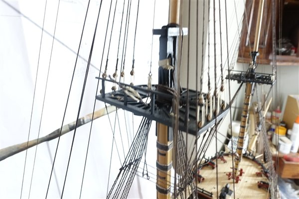
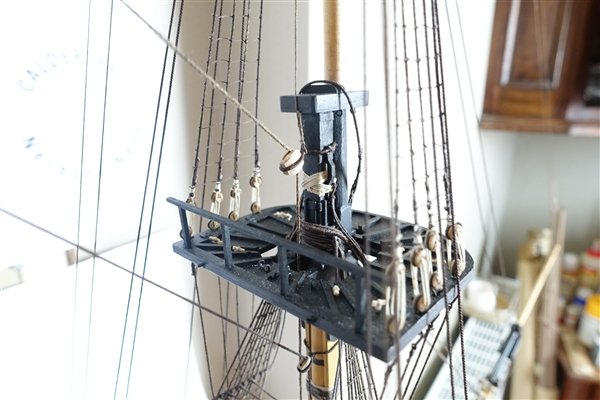
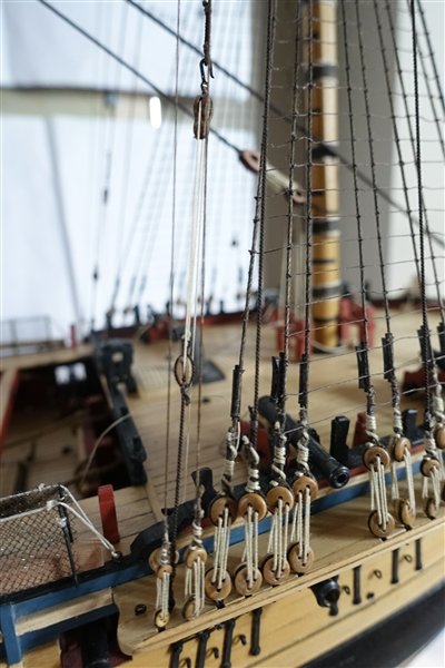
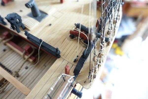
The whole 9 Yards… Thanks for looking in and for the likes and comments. I made the yards according to the measurements in the AotS, although they mostly correspond closely with the Caldercraft plans. The central octagonal section was pshaped first using files and 400 grade sandpaper to finish. The round taper sections were completed in my Proxxon lathe starting with coarse 80 grit if a lot of wood needed removing, then 120 and finishing with 400. The sizes and patterns of cleats were taken from Lees rather than the plans. Lees describes stop cleats on the fore topsail yard rather than the sling cleats shown on the plans. I have followed Steele’s tables as closely as possible for the sizes of blocks. I would have liked to have used the correct pattern for the sheet blocks but I couldn’t find any commercially available. Perhaps next time I'll have a go at making them myself. Slings are made from served rope made into a loop with a false splice. A thimble is secured in the middle with a seizing before looping round the yard. I have adopted the kit pieces for the boom irons on the lower yards. The soft metal yard-end pieces are big and bulky. They were cut and filed down until they looked more in proportion. For the outer rings I used some brass pieces left over from HMS Fly which looked more in proportion. When it came to the irons for the topsail yards, I found that using the kit pieces was unworkable, they just looked too big and ugly, so I scratched them from brass rod and styrene tube painted iron grey with Tamiya XF-18. All horses and stirrups were made from 0.5mm rope stained with wood dye as described in an earlier post. The horses are looped around the yards using a false splice The stirrups are fixed at the correct length with a false splice and the the tail wrapped around the yard three times and fixed with dilute pva. The footropes will need some work once the yards are fitted and rigged to get them to lie correctly. David

- 310 replies
-
- 9
-
-
- Diana
- Caldercraft
- (and 1 more)
-
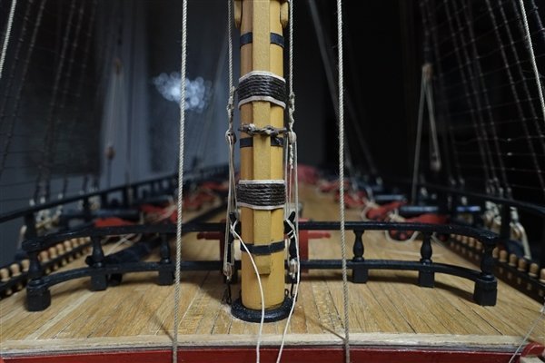
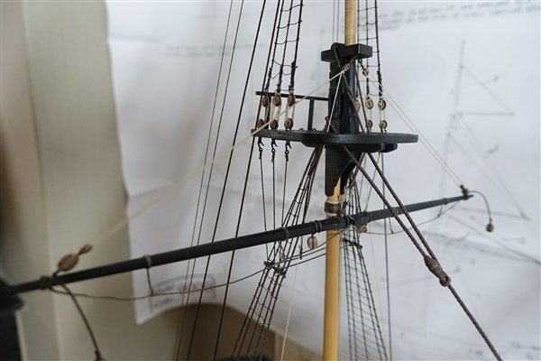
I like the idea of displaying Diana on keel blocks and was planning a similar presentation so it will be interesting to see how you progress with it. BE used a similar approach to display his model of Pegasus ... https://modelshipworld.com/topic/15526-hms-pegasus-by-blue-ensign-finished-victory-models-164-scale/page/9/#comment-489642 Regarding the main and fore masts, I also had the the problem of the diameter being too large for my Proxxon lathe. I made the section below deck to the diameter in the plan. A cheat but as this area can't be seen, I thought it acceptable. The mast above the partner is sized according to the AotS. If I remember rightly, I planed the main mast from 13mm dowel and sanded it in the drill until the top section would fit in the lathe. David
-
Congratulations David, on starting your build of Diana. I'll be following along with interest. I'm with DavidEN on the gunports. I adjusted their position to miss bulkhead 3 but there are consequences further down the line. Particularly affected are the channels and positioning of shrouds, which in turn affects the quarter deck gun placements. David
-
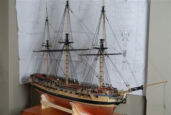
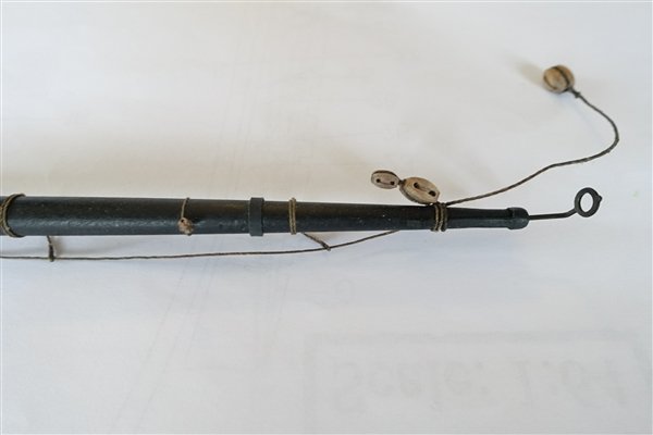
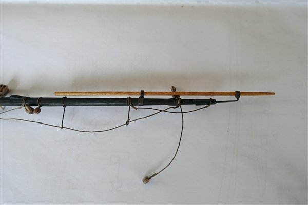
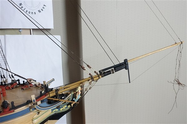
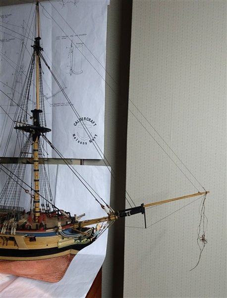
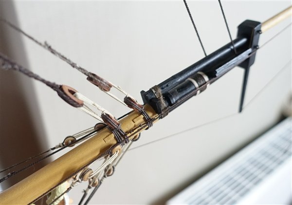
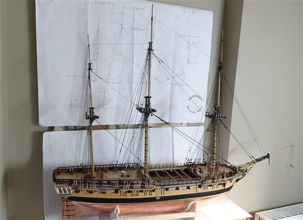
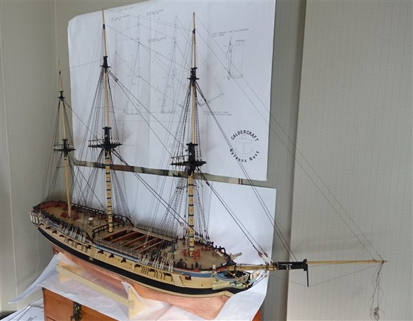
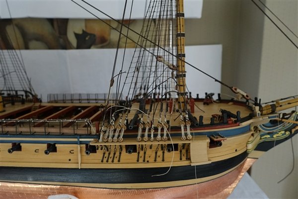
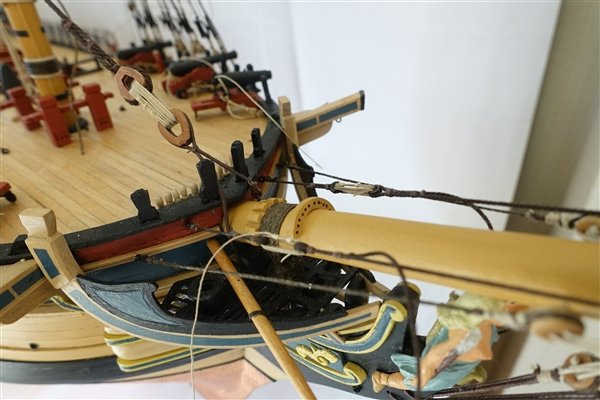
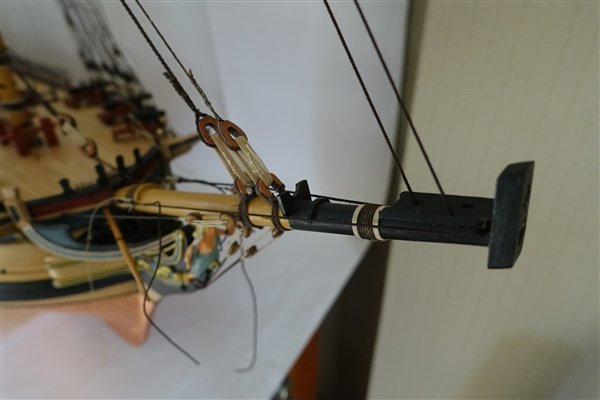
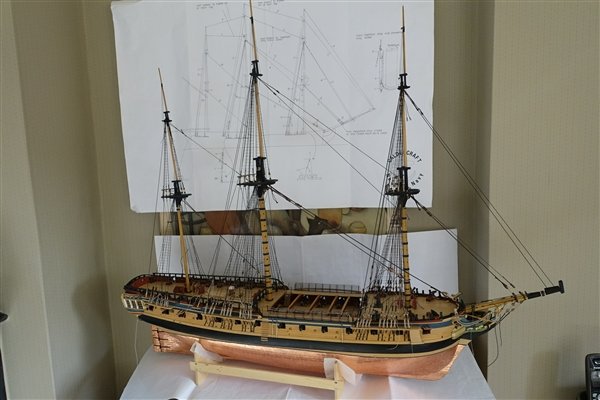
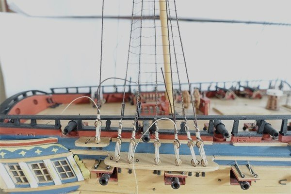
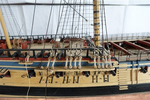
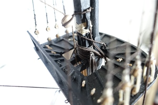
Thanks again for all the likes and comments. I made the jib a little while ago with all the lower yards, stuns’l booms, mizzen gaffs and some of the spare masts. I will cover these as we go on. The jib was made to the specification in the AotS as were all other yards and masts. The bowsprit cap was made from scratch because the kit part did not allow for the holes to be changed to the correct angle. It was also too narrow to fit a jack staff. I used the kit dolphin striker which was glued and pinned to the cap. Before fixing the jib, I added the 'lead' saddle for the spritsail yard which unfortunately doesn't show up well in the photo. This was simply made from a piece of paper (200gsm I think) painted iron grey. The heel lashing is 7 wraps of 0.5mm rope. I wasn’t sure of the order of rigging for the jibboom so followed the order given in Lees, starting with the guy pendants (0.4mm) followed by the horses and the martingale. The horses (0.75mm rope) are knotted with figure-of-eights every 10mm. The horses and pendants are left hanging for the moment. The martingale stay and back stay (0.4mm) are one piece and lead back, via a fall, to the port side of the bowsprit. The mizzen topgallant stay is made from 0.4mm rope and leads through a thimble in the main topmast head and finishes with thimbles and lanyard at the main top. According to Lees the royal stay wasn’t introduced until after 1810 so I have left it off. The back stays lead to the stool abaft the mizzen channel, the topgallant to a 2.5mm deadeye and the royal to an eyebolt. I realise that there is some inconsistency here in that there is a royal backstay but no stay. Maybe I should have left both off and I may go back to it later but I quite like it as it is. The main mast topgallant stay (0.5mm) leads through a 3mm block on the fore topmast head down to the forestay where it is tied off at the collar of the topmast stay lead block. I should have made the strop so that it stood more proud of the mast to improve the run of the topgallant stay but too late now. The royal stay leads through a 3mm block at the fore topmast head and ends in a thimble which is connected by a lanyard to another thimble fixed with a span to the fore topmast cross trees. I realised, too late, that the span should be tied into the inside of the cross trees before fitting the masts, so I have had to tie them to the outside. Back stays run down to the stool abaft the main channel. The foreamast topgallant stay leads through a 3mm block on the jibboom and runs back to the forestay collar where it is tied of with three seizings, The royal stay leads to the end of the jibboom where it is tied off. Backstays are set up in a similar manner and lead down to deadeyes on the foreward channel. I have looked again at the main and fore topmast shifting backstays and decided to re-rig them in a way more in line with the description in Lees. I’m puzzled when Lees says that the pendants were half as long again as the burton pendants. I interpreted this to mean that they would end high up off the deck which didn’t seem right and wasn’t in line with the drawing in AotS. I have rigged the pendants to come to within 90mm of the deck. The falls are set up as in Lees with a long tackle block hooked to the pendant and a single 3mm block hooked to an eyebolt in the channels. The main topmast shifting backstay falls are tied off to a belay pin but the foreward shifting backstay, according to the Caldercraft plan, is tied off to a shroud cleat and would lie across the shrouds. This seemed wrong to my eye so I have fitted a deck cleat, not shown on the plans, to tie it off which I think works better. The standing rigging is now complete and means another milestone in the build is reached just over two years from when it began. Thanks for looking in David
- 310 replies
-
- 12
-
-
-
- Diana
- Caldercraft
- (and 1 more)
-
Well done Andrew, that is a wonderful model and I love all the extra detailing which really brings it to life. David
- 206 replies
-
- 2
-
-
-
- Vanguard Models
- Brixham trawler
- (and 2 more)
-
Thanks for your kind words Brian. MSW is a great source of information and support and is how I have learnt whatever 'mad skillz' I have but there is so much more that I have to learn. By the way, my wife thinks that I am mostly just mad! David
- 310 replies
-
- 2
-
-
- Diana
- Caldercraft
- (and 1 more)
-
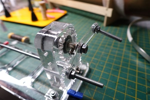
Thanks very much Andrew. I bought the serving machine three or four years ago from Domanoff in Minsk. I bought it before the war in Ukraine and it may not be available for import into the UK now. There are other machines on the market, for example from Syren Ship Model Company or YouTubes on how to build one. David
- 310 replies
-
- 3
-
-
-
- Diana
- Caldercraft
- (and 1 more)
-
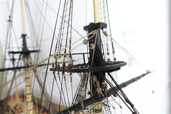
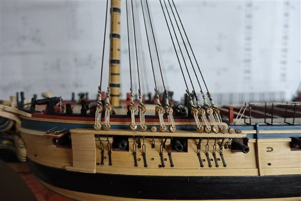
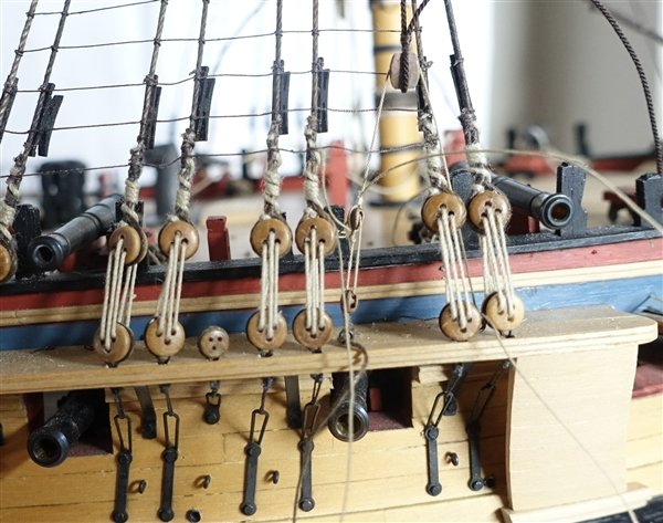
Thanks to all for the likes. Fitting of standing rigging continues and is complete to the level of the topmasts except for final trimming of the ends of stays. The shifting backstays on fore and main masts are described in Lees as being set up from a pendant half as long again as the burton pendant. A long tackle block is hooked into the pendant and single blocked hooked into the channel. My interpretation of the AotS drawing is that they are set up in a similar fashion to the other back stays at the upper end but with a long tackle block seized in the lower end. The falls are a singe block hooked into the channel. I can see the logic of the Lees version but I decided to go with the AotS which I thought looked better. The fore topmast stays are made from 0.8 and 0.7mm rope and both are served as before. A minor disaster struck as I was partway through serving the first rope when the winding handle of my serving machine broke in half. I repaired it by super-glueing the two halves together and then it was reinforced with a bit of brass sprue which I fixed with epoxy. The stays are threaded through the bees: the preventer stay to the aft port and stay through the forward starboard ‘sheave’. The stays end in a thimble connected by a lanyard to a thimble secured to eyebolts at the bow either side of the bowsprit. The topgallant stays are next which will require me to fit the jibboom David
- 310 replies
-
- 13
-
-
- Diana
- Caldercraft
- (and 1 more)
-
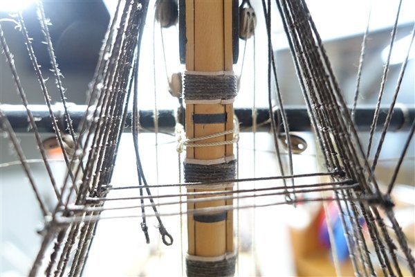
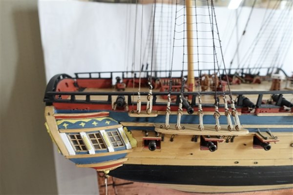
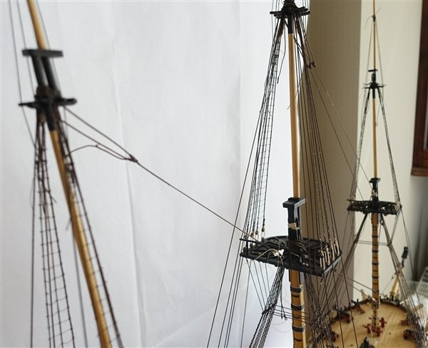
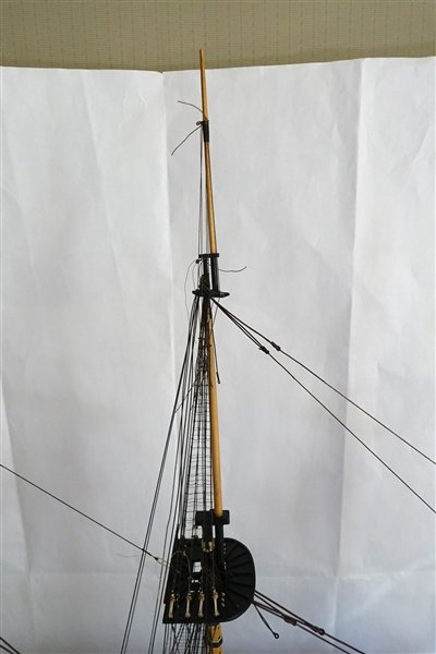
I have begun to add the topmast and top gallant stays. Beginning with the mizzen mast, I remembered why I was going to rig stays to each level of masting before adding the next. Luckily I had decided not to glue masts and mast caps in place so although more awkward than it ought to have been, looping the backstays over the mast head was not difficult. I used 0.6mm rope from Ropes of Scale on the mizzen backstays and 0.7mm for the stay. The stay was served to 30mm below the level of the mouse (I don’t propose to serve any ropes finer than this) and finishes in a thimble which is attached by a lanyard to another thimble tied to an eyebolt on the main top. Both stay and backstays are set up but not finally tensioned until all the masts are completely rigged. I started to rig the main topmast. The breast backstay and the first of the standing backstays are rigged using 0.7mm rope, again not finally tensioned, but I have run out of 5mm deadeyes so can’t continue until supplies arrive from CMB. Shifting backstays on the main mast are shown in both the AotS Diana and the Caldercraft rigging plans but Lees says that they would not generally be seen as they were only used when sailing. However, I am minded to fit them as I think that they do add something to the model. The topmast stay and preventer stay are fitted: the stay from 0.8mm and the preventer stay from 0.7mmrope. Both are served to 30mm below the mouse. The stays lead down through 5mm blocks fitted to the foremast and end in a long-tackle block. The falls are set up with a single 5mm block hooked to eye bolts in the deck each side of the foremast, the stay to the port and preventer to starboard. While waiting for more fittings, I have made a start on the fore topmast. The breast backstays are fitted first using 0.7mm rope with a 5mm block seized in the end. The tackles are rigged with 0.25mm thread tied to an eyebolt in the forward channel passed through the block of backstay and ending in a 3mm block. The fall is spliced to a second 3mm block hooked to another eyebolt abaft the first and is threaded through the upper 3mm block. The fall is tied off to a timberhead. It was at this stage that I noticed that I had rigged a shroud where there should be a backstay. I wondered about carrying on rigging with one backstay less but decided in the end to do the right thing as far as I could. It would have been impossible at this stage to remove the last two pairs of shrouds and replace them correctly so I did the next best thing and carefully cut out the 9th shroud all the way to the mast head where I don’t think (hope) that this fix will be noticed. Cutting out all of the ratlines and retying them was a step too far so the new ratlines were tied in to the existing ones. the offending shroud removed and ratlines restored but looks like a good clean up is required now. Thanks for the likes and for looking in David

- 310 replies
-
- 10
-
-
- Diana
- Caldercraft
- (and 1 more)
-
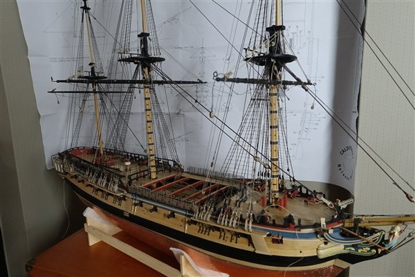
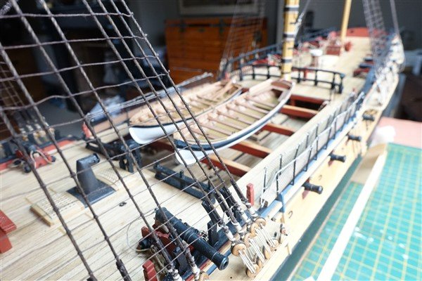
I haven't decided how to display them yet. If I mount them on the skid beams a lot of the upper deck detail will be hidden. I will probably hang one from the mainstay tackle pendants. I may mount one or two separately within the display case.
- 310 replies
-
- 5
-
-
- Diana
- Caldercraft
- (and 1 more)
-
The Vanguard Model instructions for the cutters only show them as carvel planked. I think that I'm going to have to do a lot of reading and trialing before I make a start on them.
- 310 replies
-
- 1
-
-
- Diana
- Caldercraft
- (and 1 more)
-
Thanks Allan. You've found me out! I've never built a lapstrake boat before and I'm putting it off for as long as possible. David
-
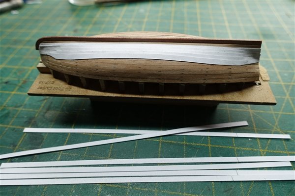
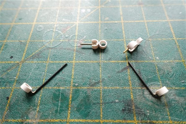
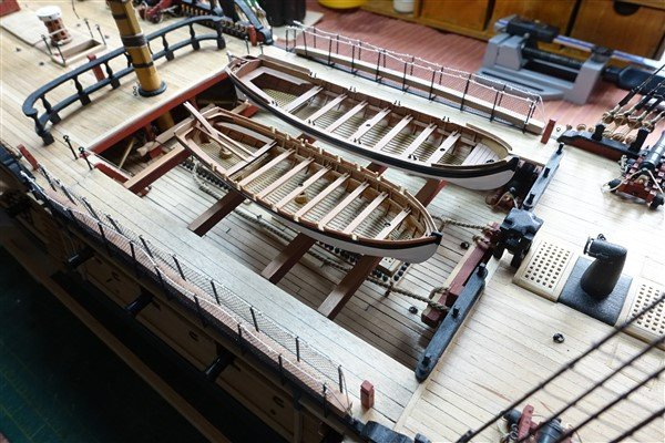
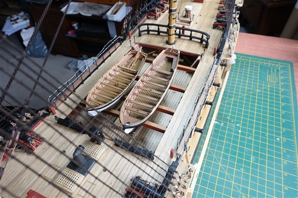
There was quite a lot of filling and sanding to do on the hull as it turned out but I am reasonably satisfied with the result. The wales were added and the hull painted matt white. I followed BE’s treatment of the wash strake and rowlocks by adding a strip of spare seat support around the inside edge to both strengthen and give support to the wash strakes and tholes. Mast and davit steps were added, made from 6mm dowel. I doubled up on the thickness of the davit by cutting another piece from around the original. I cut a slot and added a blackened pin of 0.75mm brass rod to represent the sheave. I would like to have added the windlass but I had already fitted the thwarts according to the kit design, which didn’t leave sufficient space. (that was the rationale that I used anyway). Finally, I fitted the knees which although even smaller than on the pinnace, proved less troublesome when fitted last. A couple of coats of diluted matt varnish and the launch is finished. The boats are placed temporarily on the skid beams to see how they look. With the pinnace and launch completed, it’s time to return to the main ship and continue with the rigging of the masts. The two cutters will be left for later perhaps as a break during fitting the running rigging.
- 310 replies
-
- 8
-
-
- Diana
- Caldercraft
- (and 1 more)