Mahuna
-
Posts
1,504 -
Joined
-
Last visited
Content Type
Profiles
Forums
Gallery
Events
Everything posted by Mahuna
-
 Thanks Druxey. I think I'm the one who should be sending appreciation to all of the folks who have been very encouraging along the way.
 -
Thanks Jerry. I admire folks like yourself who have actually worked on these boats. I have a good friend who is an experienced waterman (and an excellent modeler) who has been a great source of info during the project. Thanks Will. I think when you see Kathryn in person you'll probably pick out some things that are NOT the best parts!
-
Thanks Patrick - but I don't think I'll be making sails again. Thanks Popeye. The JTL will be interesting when compared to skipjacks. Thanks Gary. Thanks Ed. I've tried to apply what I've learned from watching your work since I started modeling. Thanks Greg. I've actually been thinking that at some point I might offer the Kathryn to CBMM. Thanks John. I guess you could say this is how she looks at the start of each oystering season, before the paint dries.
-
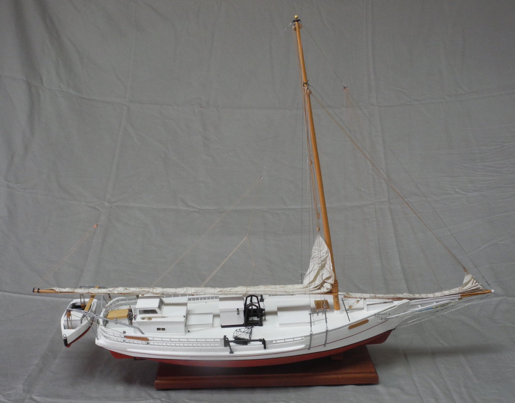
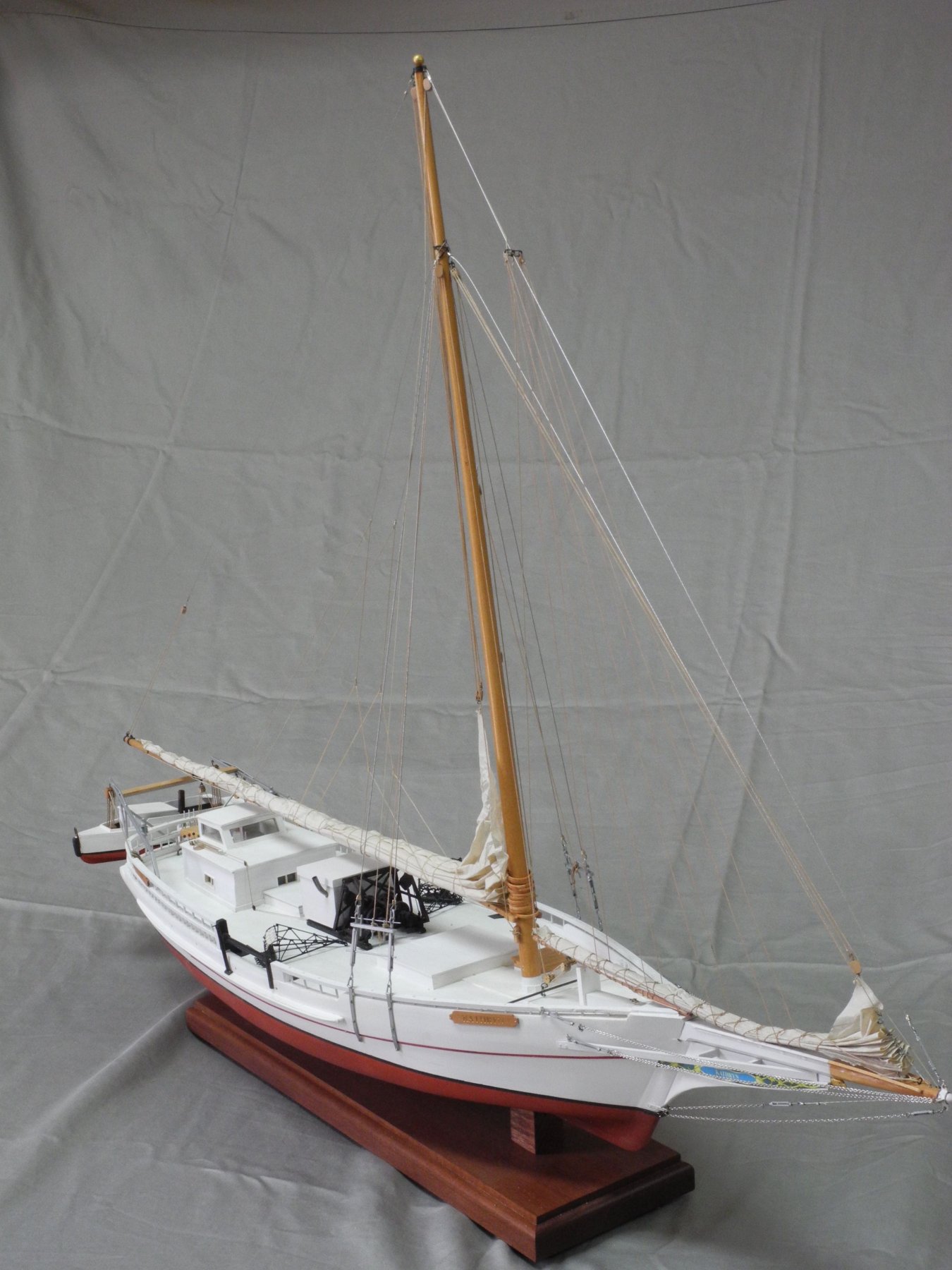
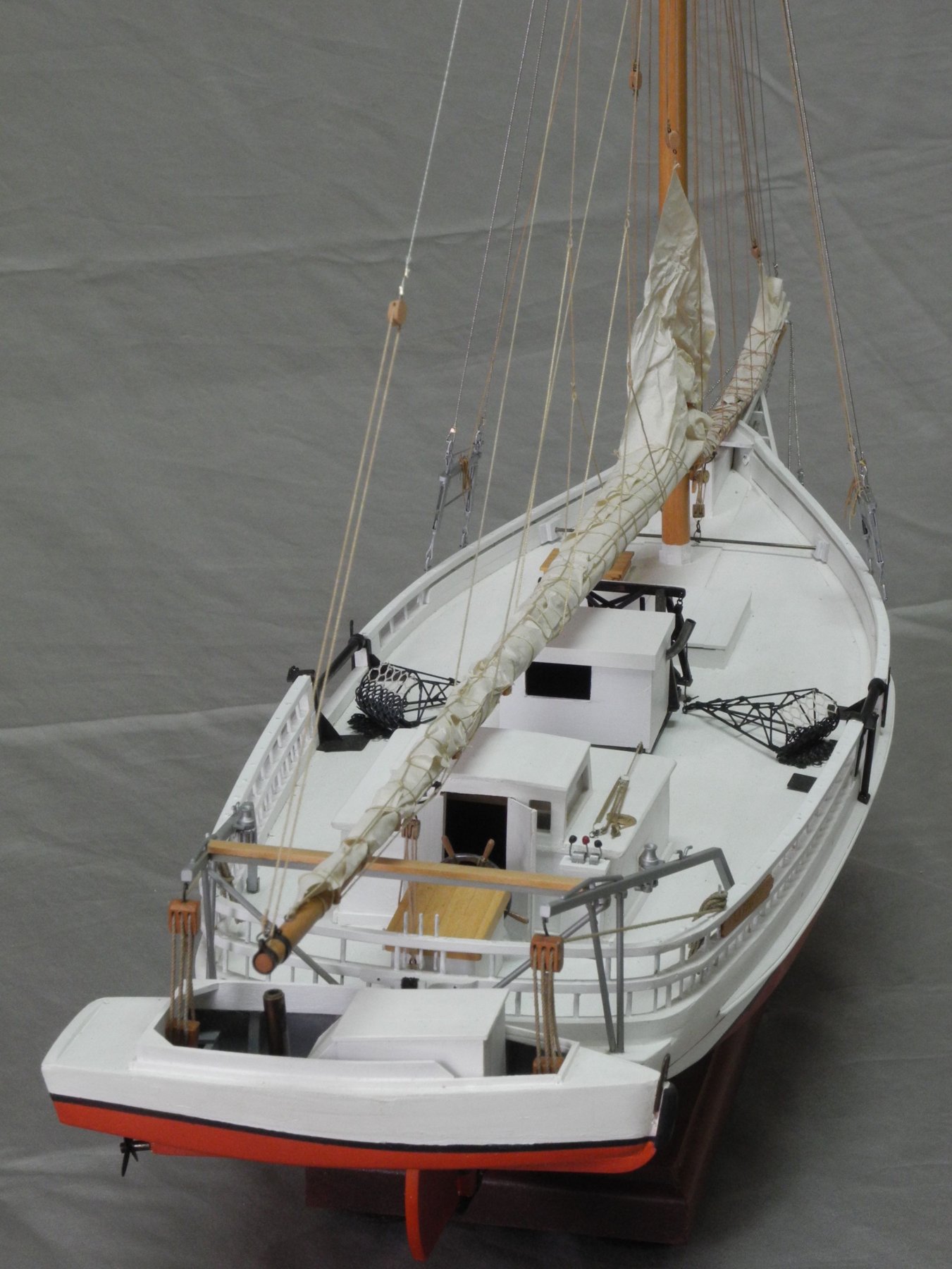
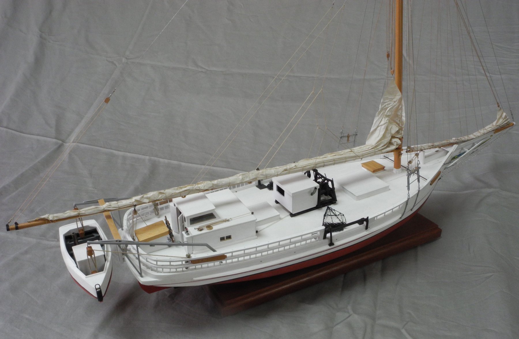
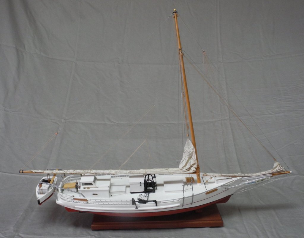
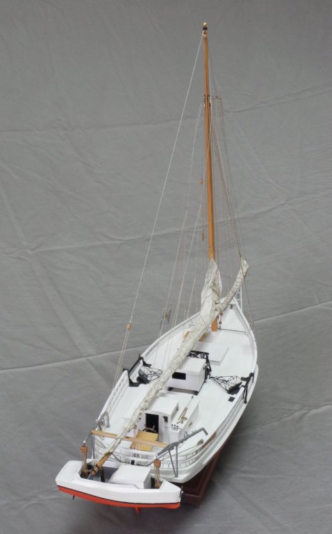
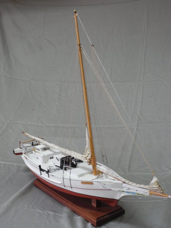
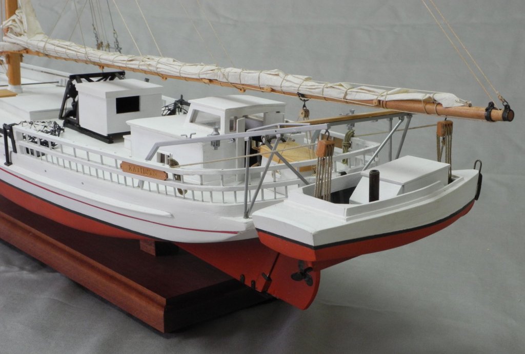
Thanks everyone for the comments, 'likes', and support during my Kathryn build. Here are a few photos of the completed model. I've started doing some CAD work for my next model - the J.T. Leonard oyster sloop. I hope to start a build log soon.


- 878 replies
-
- 21
-

-
Thanks Druxey. I did dye the netting, but it might still be a little bright. However, when you look at the whole model it doesn't stand out too much. Thanks John. It feels good to finally be 'finished'. Now on to the next one! Thanks Chris. Glad you like it! Thanks Rich. I try. 😉
-
Hi Will - I'm looking forward to your build log. (Also looking forward to meeting you next Tuesday)
-
Thanks Carl. It has been a very educational build for me, and I'm glad others have benefited as well.
-
I just added some photos of my Skipjack Kathryn build. I had named each file using a sequence number, assuming that the photos would be shown in that sequence. The photos are shown in reverse order - last in first out. I've tried sorting the album by Caption, and I see the album in the proper sequence, but the Gallery still shows the original sequence. Is there a way to resequenced the album in the Gallery?
-
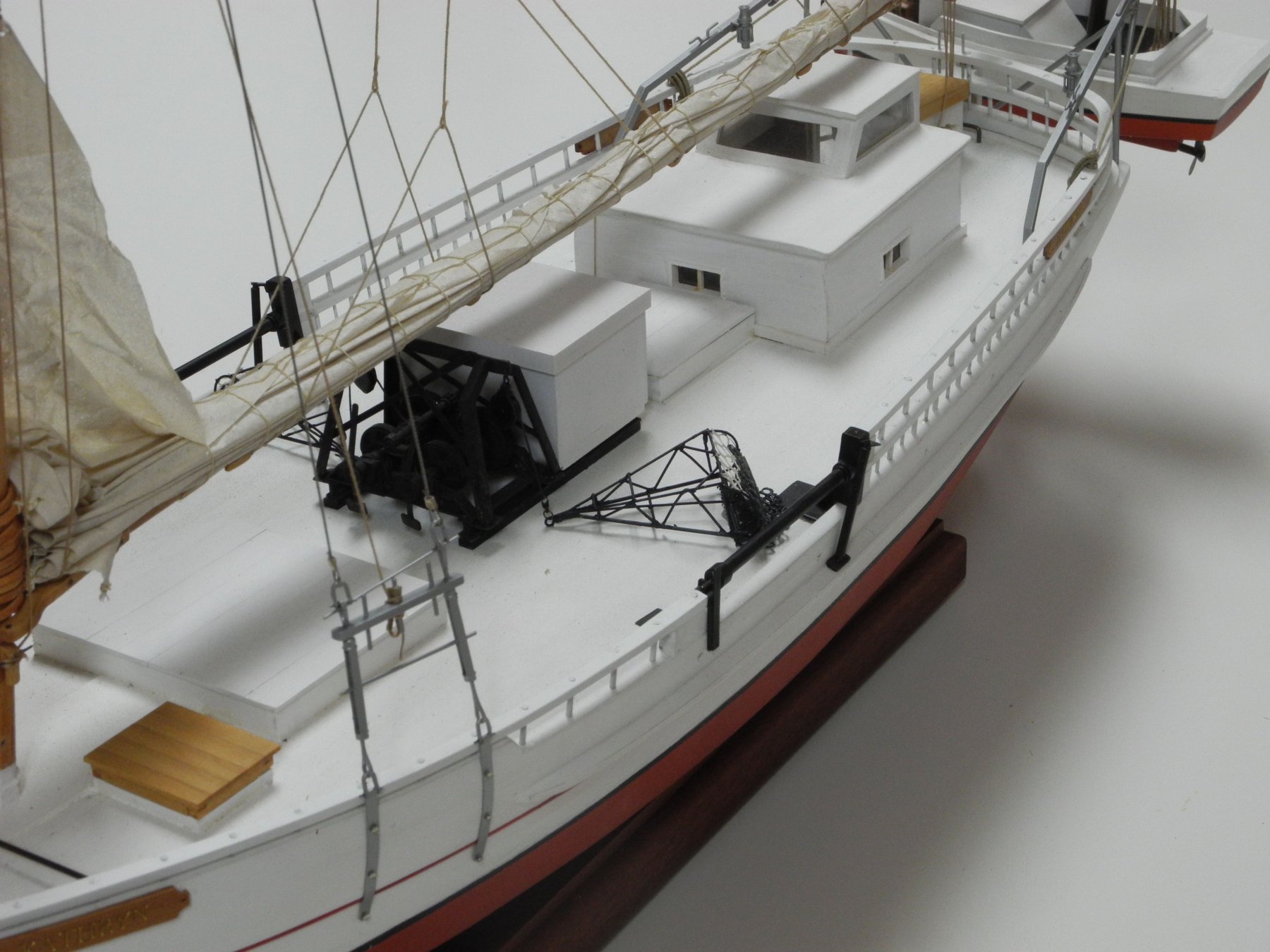
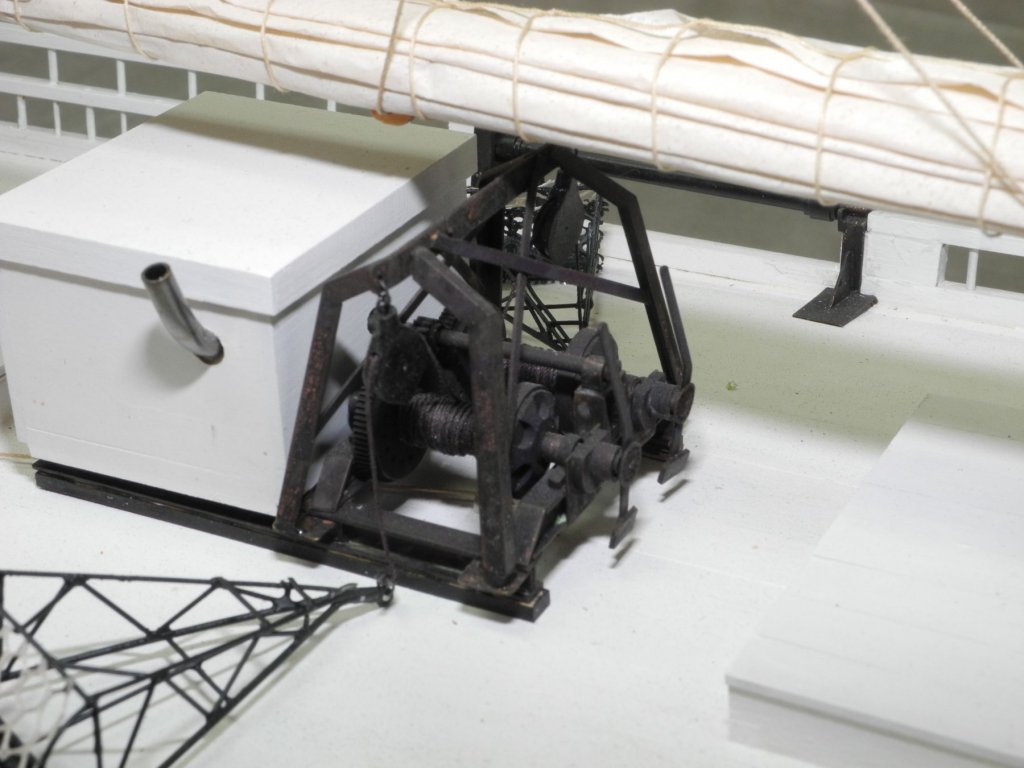
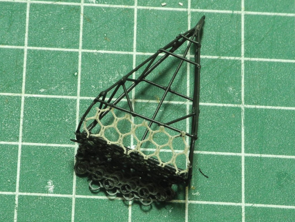
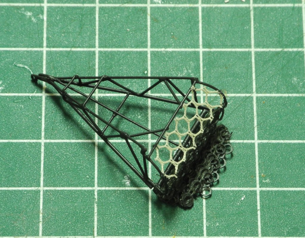
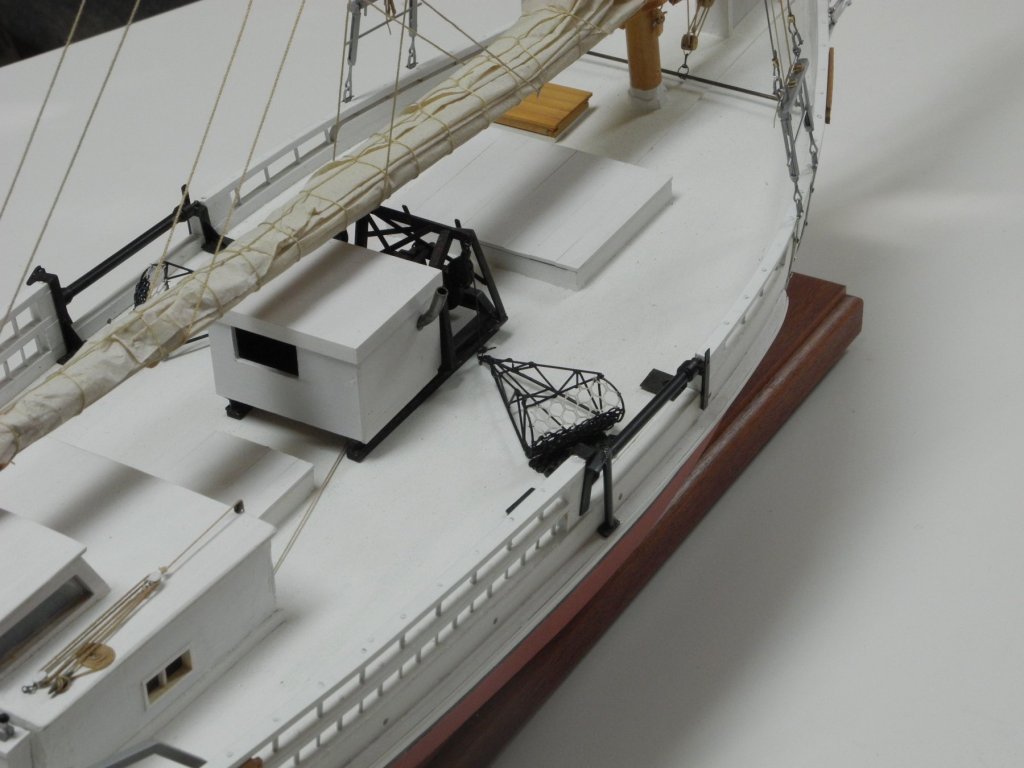
Part 104 –Oyster Dredge Cont’d My plans were to have one of the dredges sitting on the deck, and one hanging off the side. After more thought, this wouldn’t be very practical if I’m going to transport the model. The hanging dredge would likely sway back and forth, and would wind up damaging the side planks or worse. So I decided to be practical and install both dredges on the deck. The net made of rings has already been discussed. The next and last item that needed to be made was the rope net. Trying to make the net from scratch was another source of frustration, so I had to look for alternatives. The best alternative wound up being the net from a laundry bag used for delicate clothing. Here are a couple of photos of the finished dredge. After attaching the dredges to the ‘cable’ coming off the dredge winder, the dredges were epoxied to the deck. This completes the work on the model. Since I’ll likely be bringing Kathryn to a meeting of the San Diego Ship Modelers Guild, I’ll need to make sure there are no other components that may be affected by travel. I’ll share some photographs of the finished Kathryn in my next post.

- 878 replies
-
- 22
-
-
Thanks John. Making the dredges have been a little frustrating, but they're getting there. Hi Patrick. You always have interesting ideas - but maybe I'll pass, given all of the frustrations I've already had with these little devils.
-
Thanks Druxey. I'm a little disappointed that I wasn't able to make the ring net from scratch, but I'd really like to get the model finished this year. 😉 Hi John. Yes, I'll be adding the rope after I get the rings finished.
-
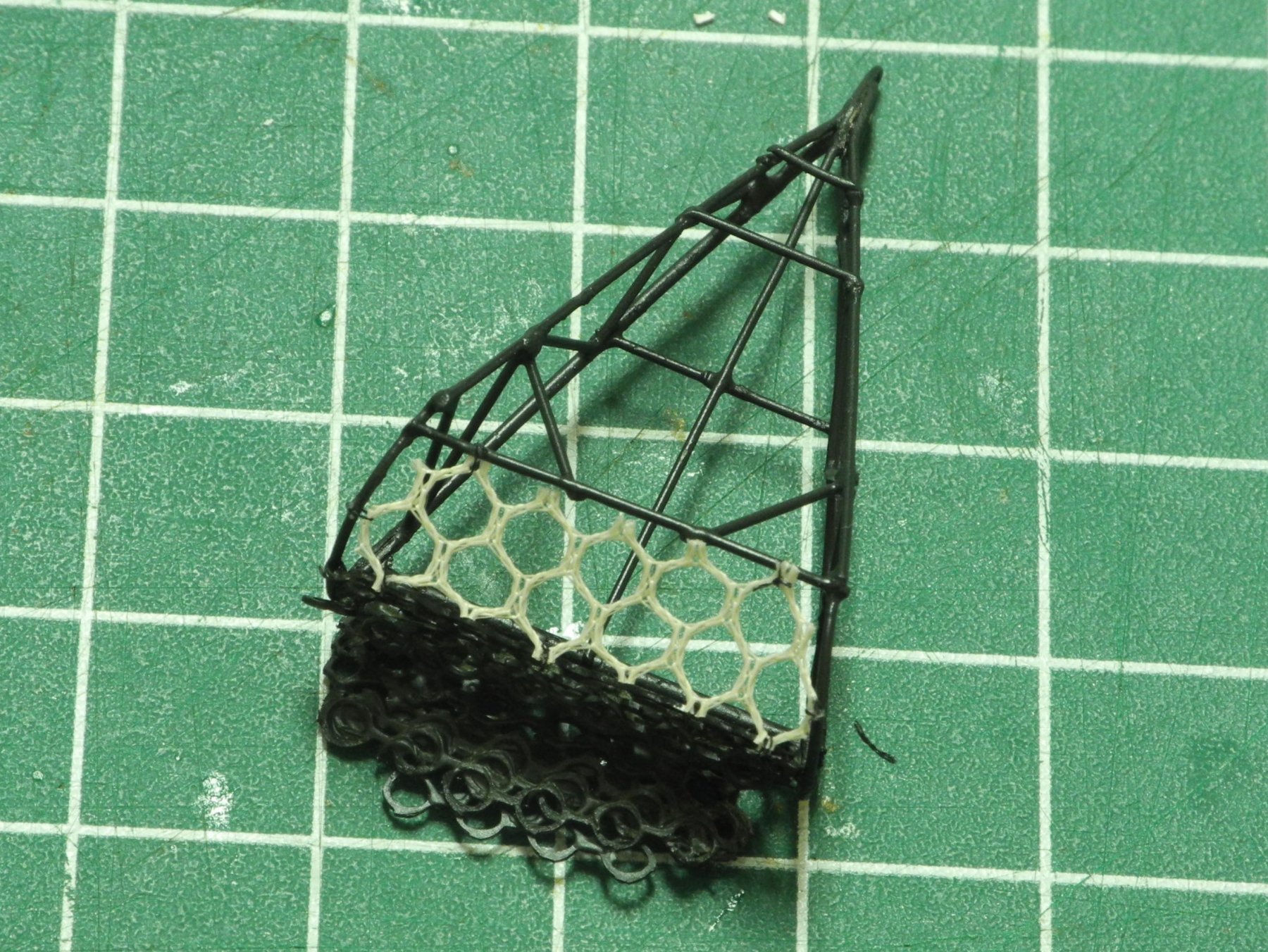
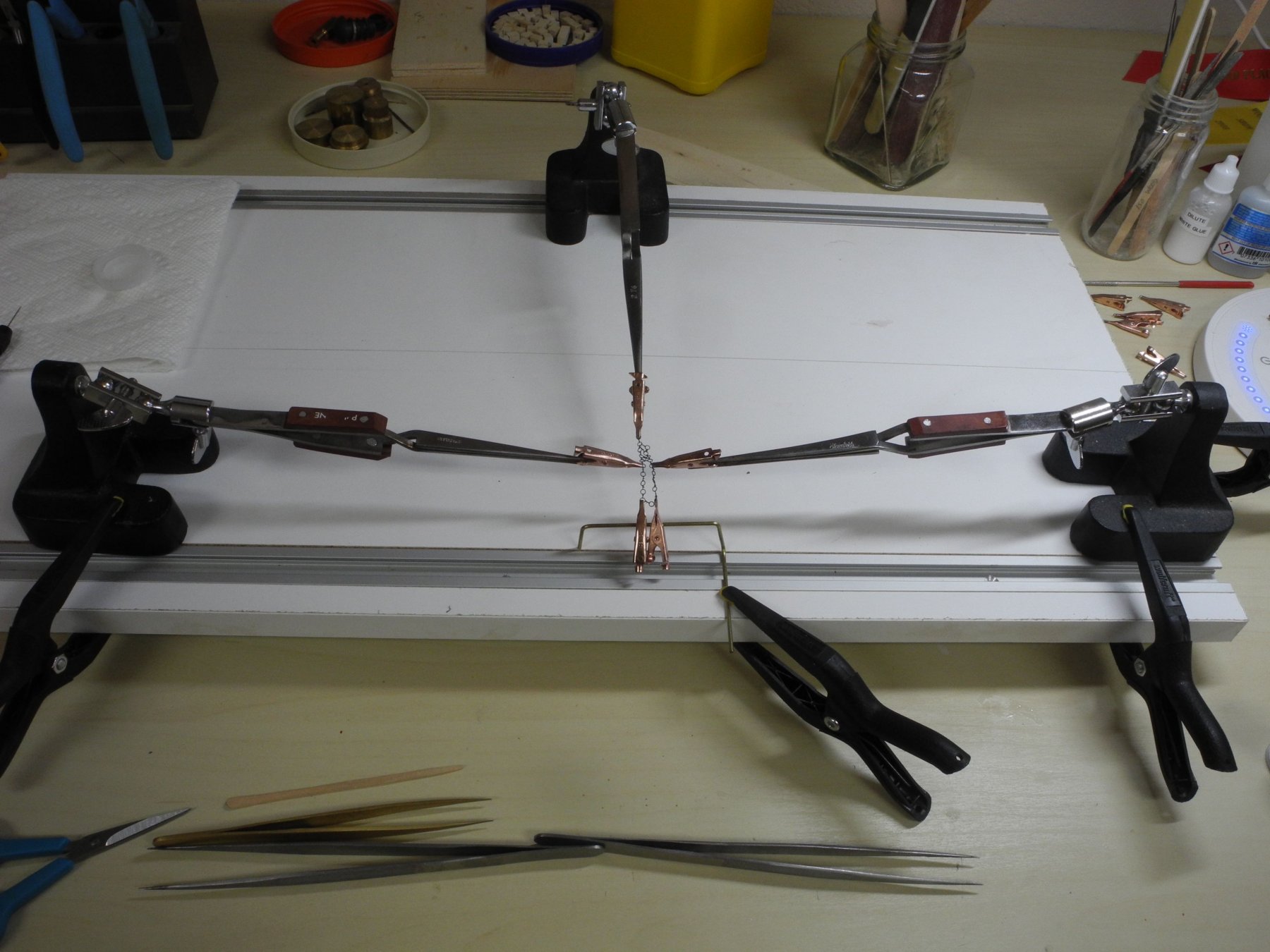
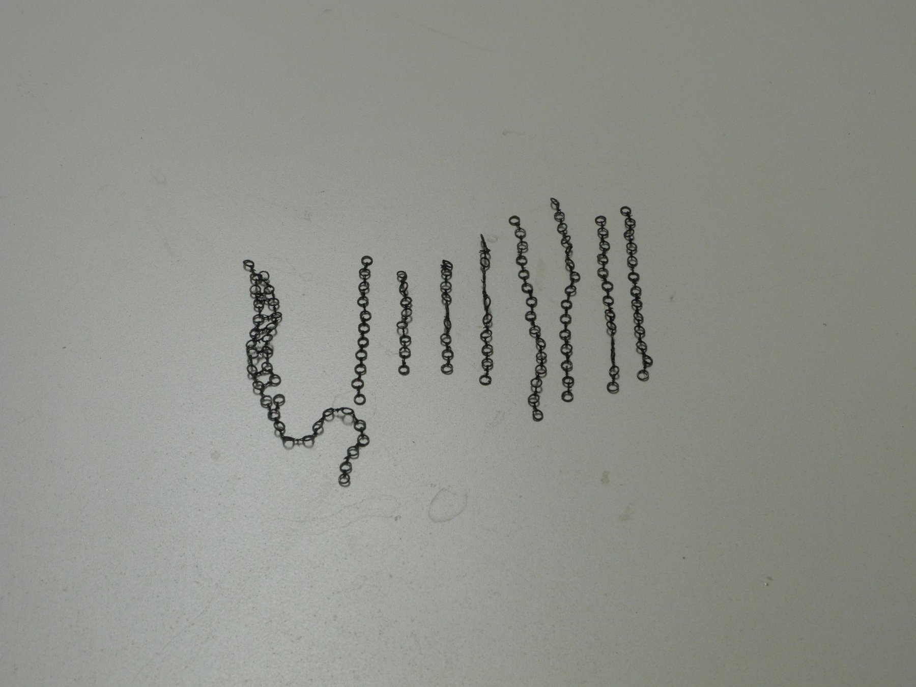
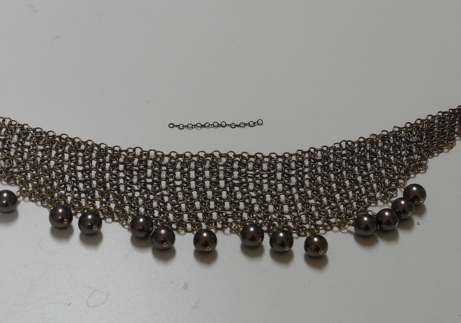
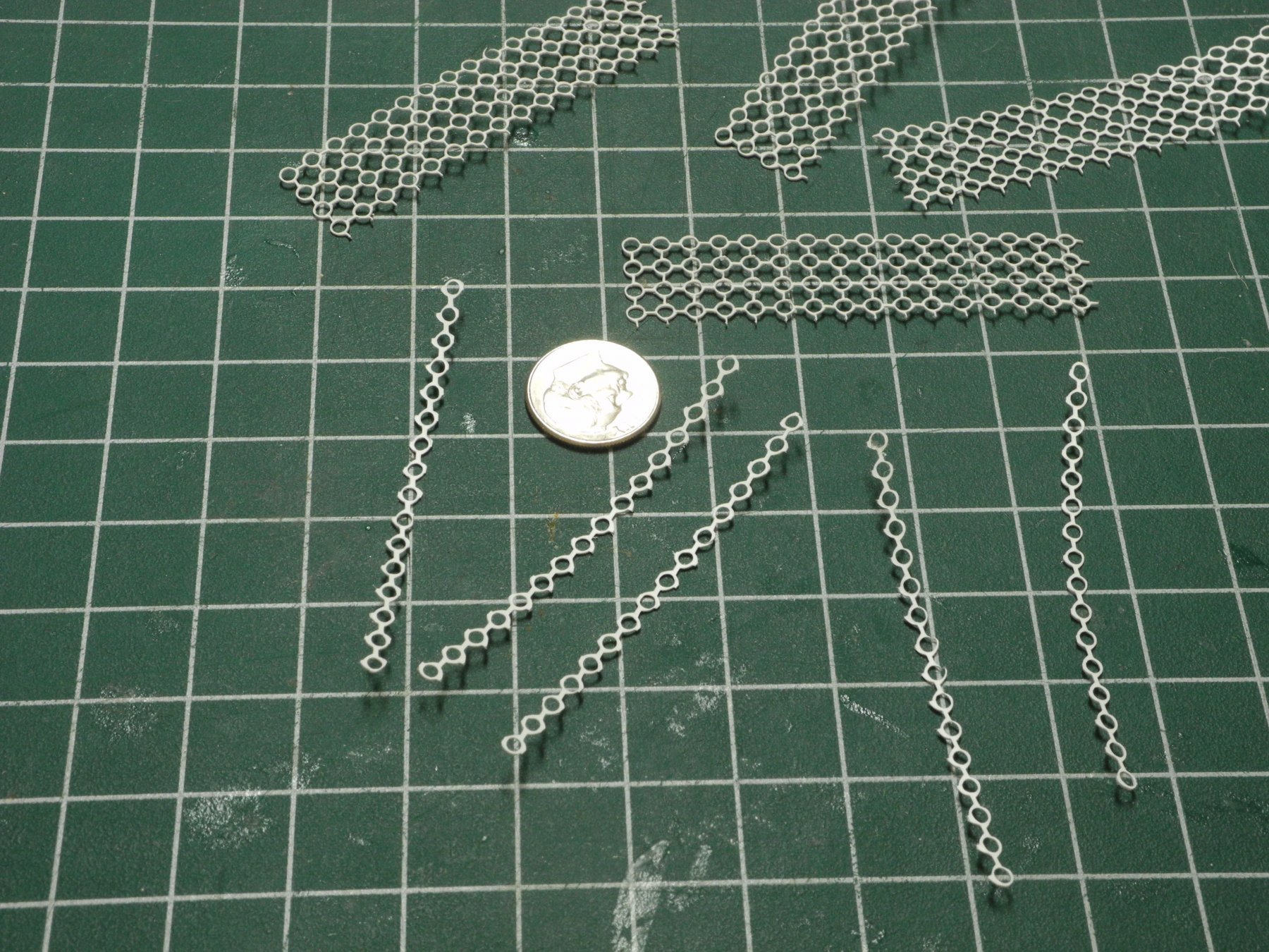
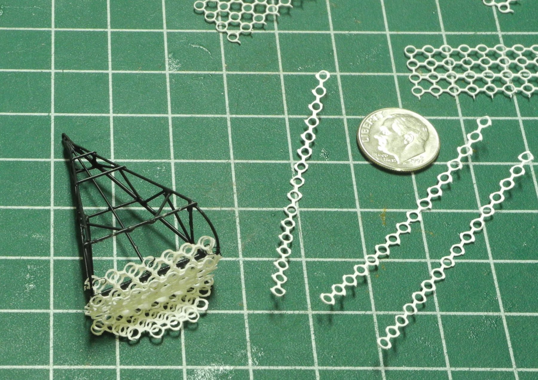
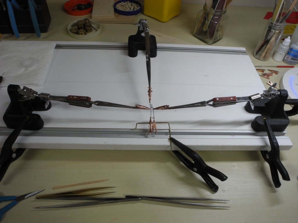
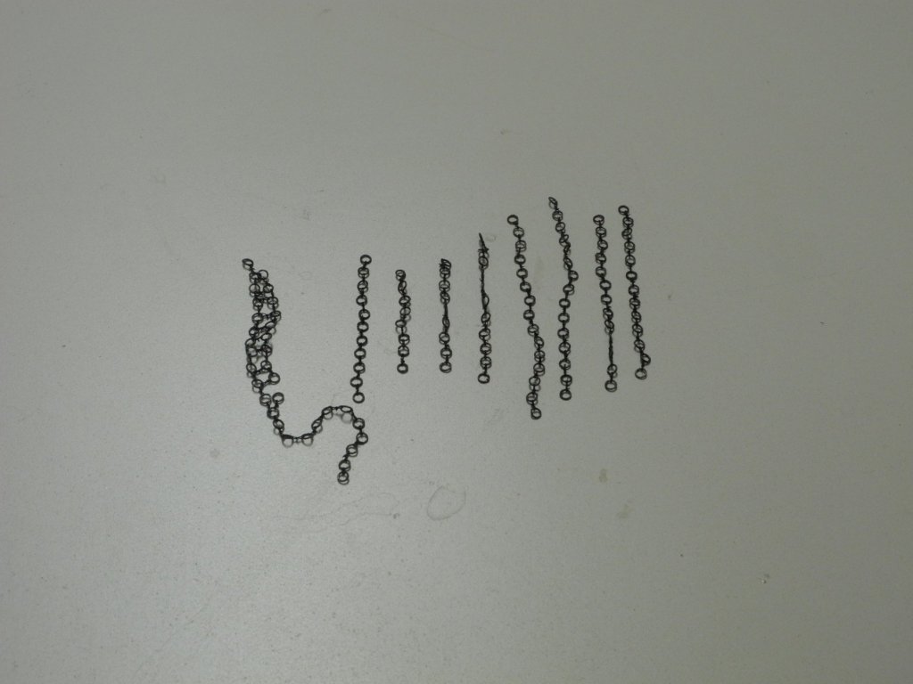
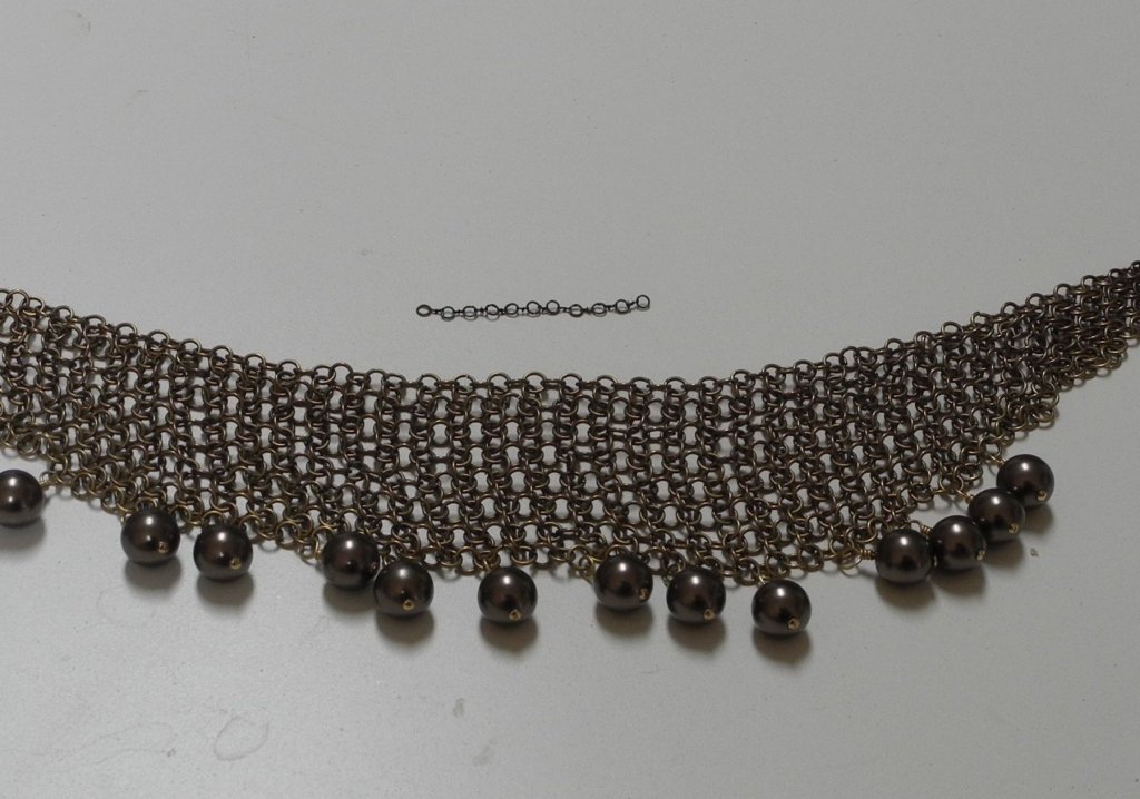
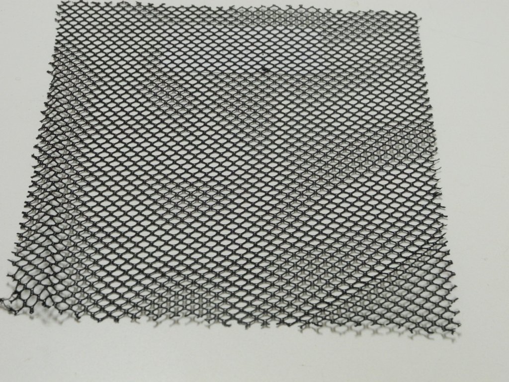
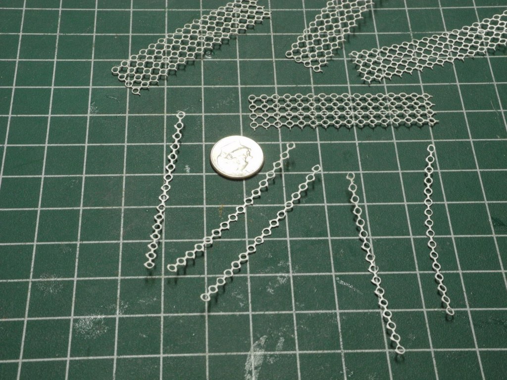
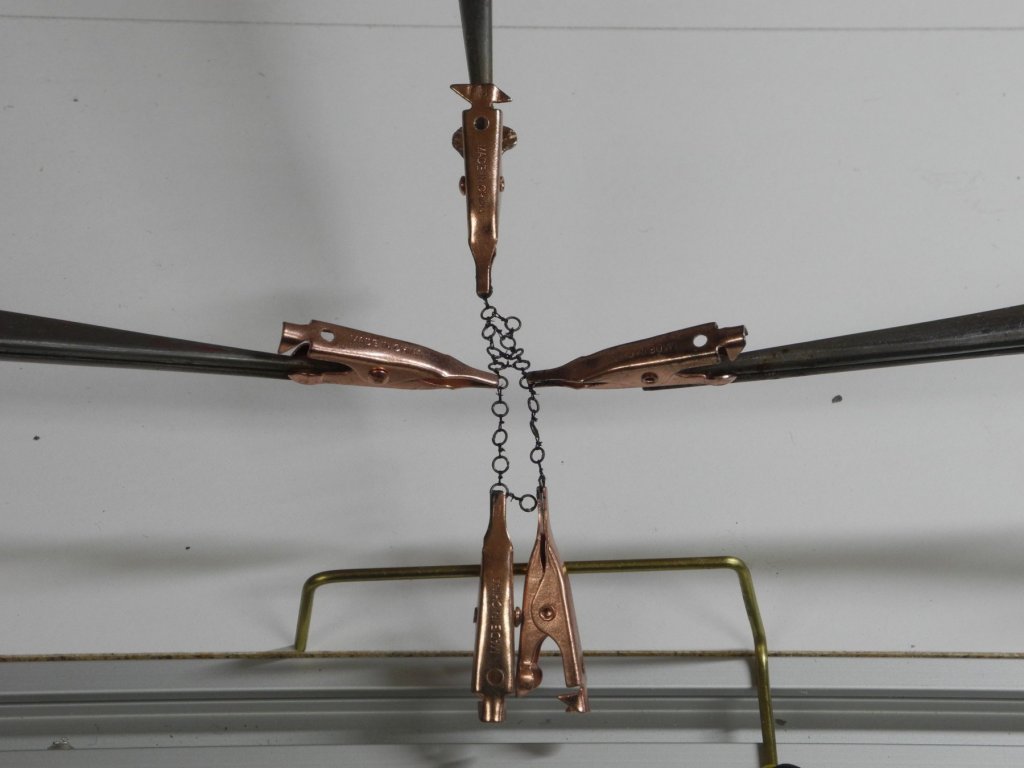
Part 103 –Oyster Dredge Cont’d Kathryn’s dredge has a net of rings and a net of rope forming the ‘basket’ of the dredge. In Part 96 (post #762) and Part 97 (post #798) I discussed my planned approach to making the ring net. I spent over a dozen hours making the strands of rings required for the net. Joining these strands into a net was the planned next step. I set up a configuration that was intended to allow me to join the strands by tying the strands together with the fly tying thread, as in the following photo. Joining the strands required tying from ring to ring along the strands. The process of joining the first two strands was time-consuming and frustrating, and when I got to the third strand it became nearly impossible to keep the strands properly arranged. I realized that making the ring net this way would take more time than it was worth, and the results would be questionable, at best. So, I looked for alternatives. My wife suggested using a piece of costume jewelry that was quite old. This would have been a great approach, but the rings were more than 3 times the size I needed. I also looked at netting fabric, and found one that would work. Unfortunately the ‘rings’ in the fabric were also too big. A friend of mine (a military modeler) has a Silhouette Cameo III cutting machine, and volunteered to try to help. Using CAD, I drew strings of rings and he reduced the scale to the smallest the cutter could produce. The resulting parts cut out of a thin plastic sheet were quite good – a little bigger than the scale called for, but would work. My hope was to produce two versions of the dredges, one sitting on the deck and one hanging off the side of the hull. I used the plastic rings to create the one for the deck first. 1 In the enlarged photo the rings don’t look that great, but in actual size they look good. After painting they look even better. The quality of the photo doesn’t do justice to the rings – I dry blended some grey on them to highlight the curves but this doesn’t show up in the photo. The next effort will be to make the dredge basket that hangs off the side.


- 878 replies
-
- 16
-
-
Thanks Druxey! Thanks Allan. The low temperature solder paste with resistance soldering worked really well on the very thin brass (.020) rod. The epoxy rescued my first attempt, but the last (and hopefully final) dredges have the tongue built in. Thanks Patrick - it's good to be back at 'work'. Hi Peter. Yes, I did some initial drafting for the next model while away on vacation. I'll probably start a new log in a month or so.
-
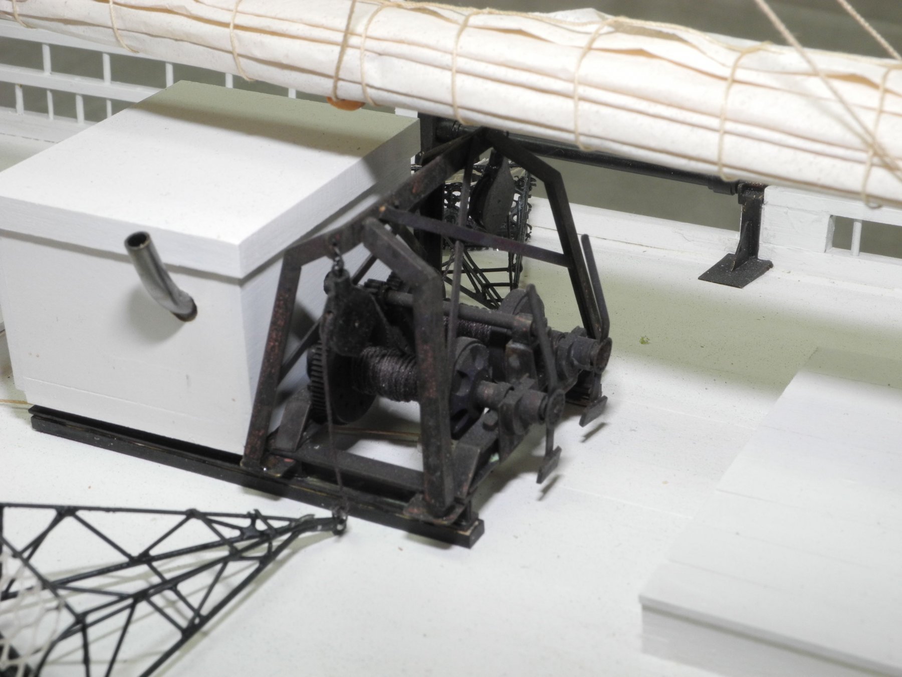
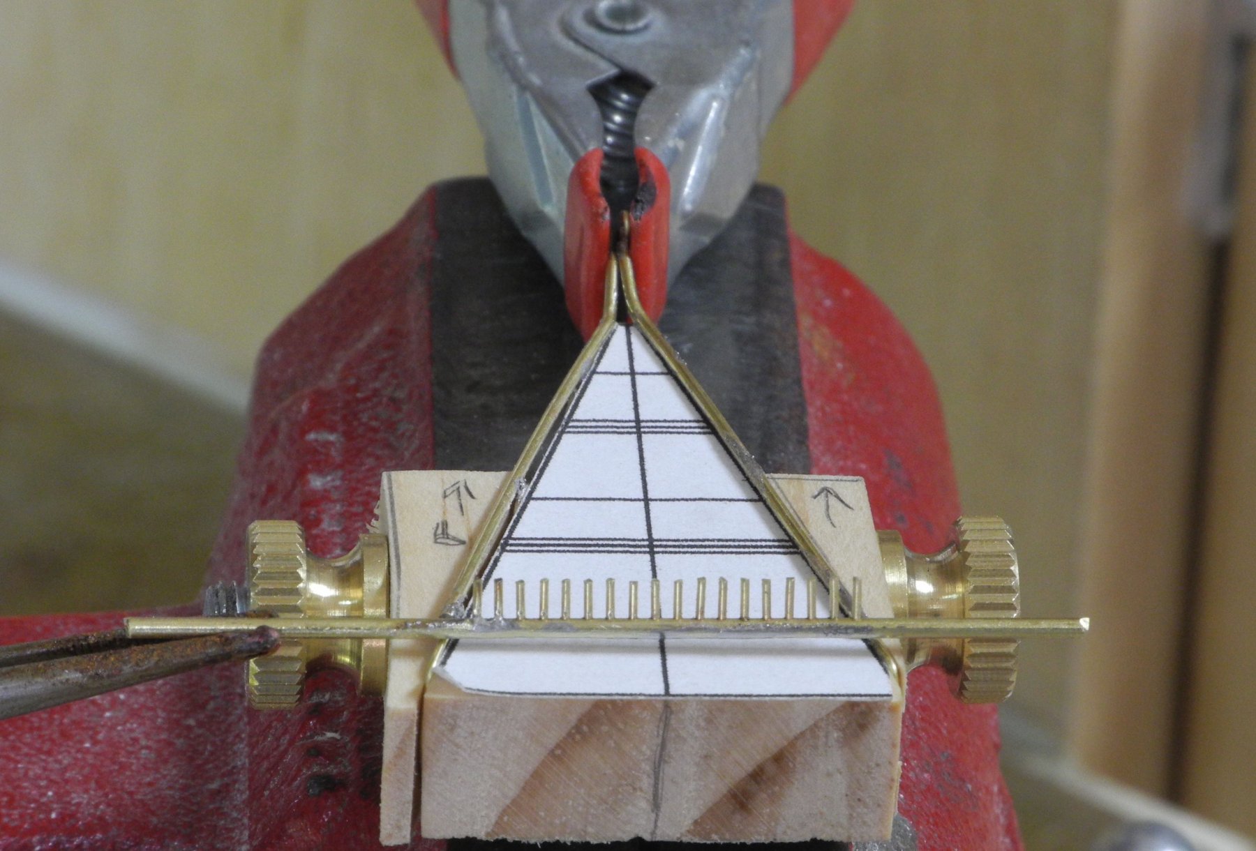
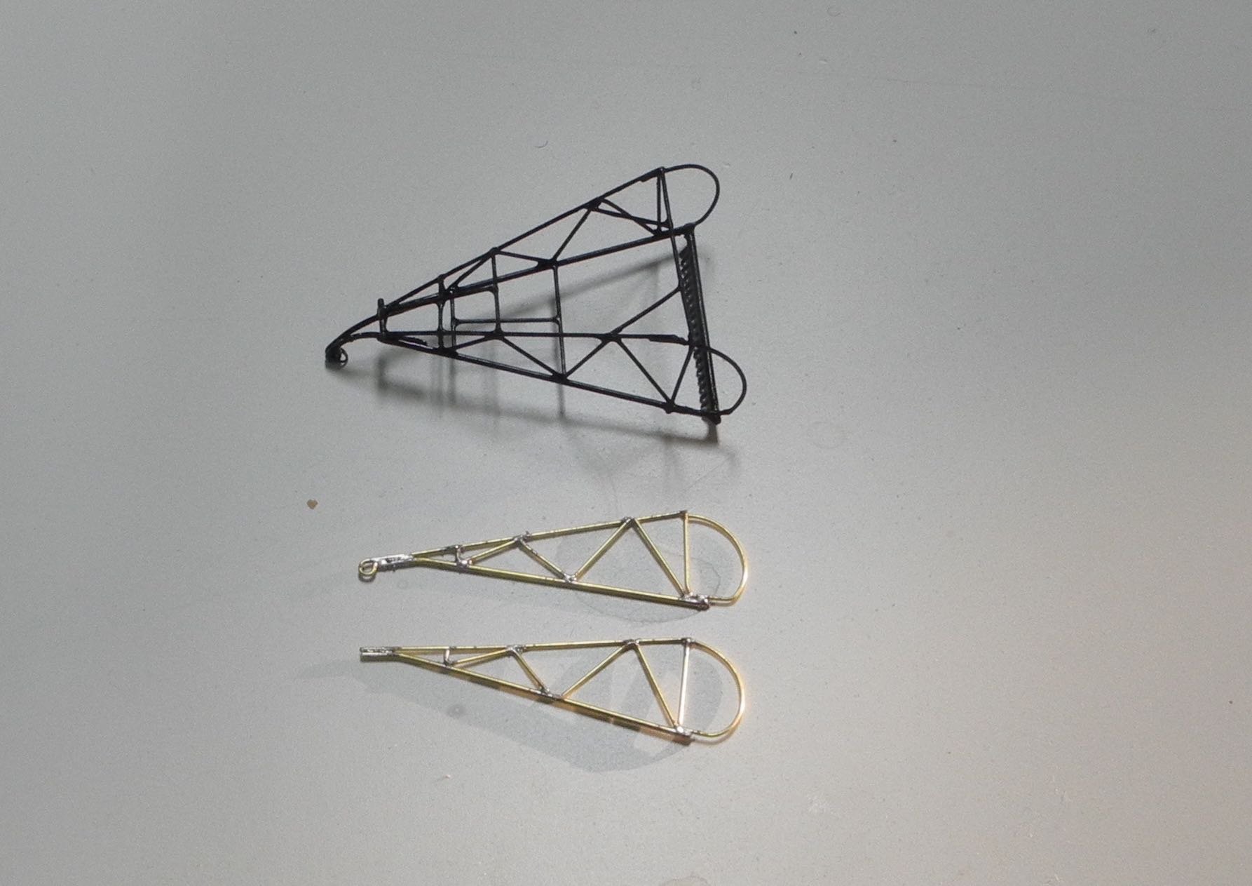
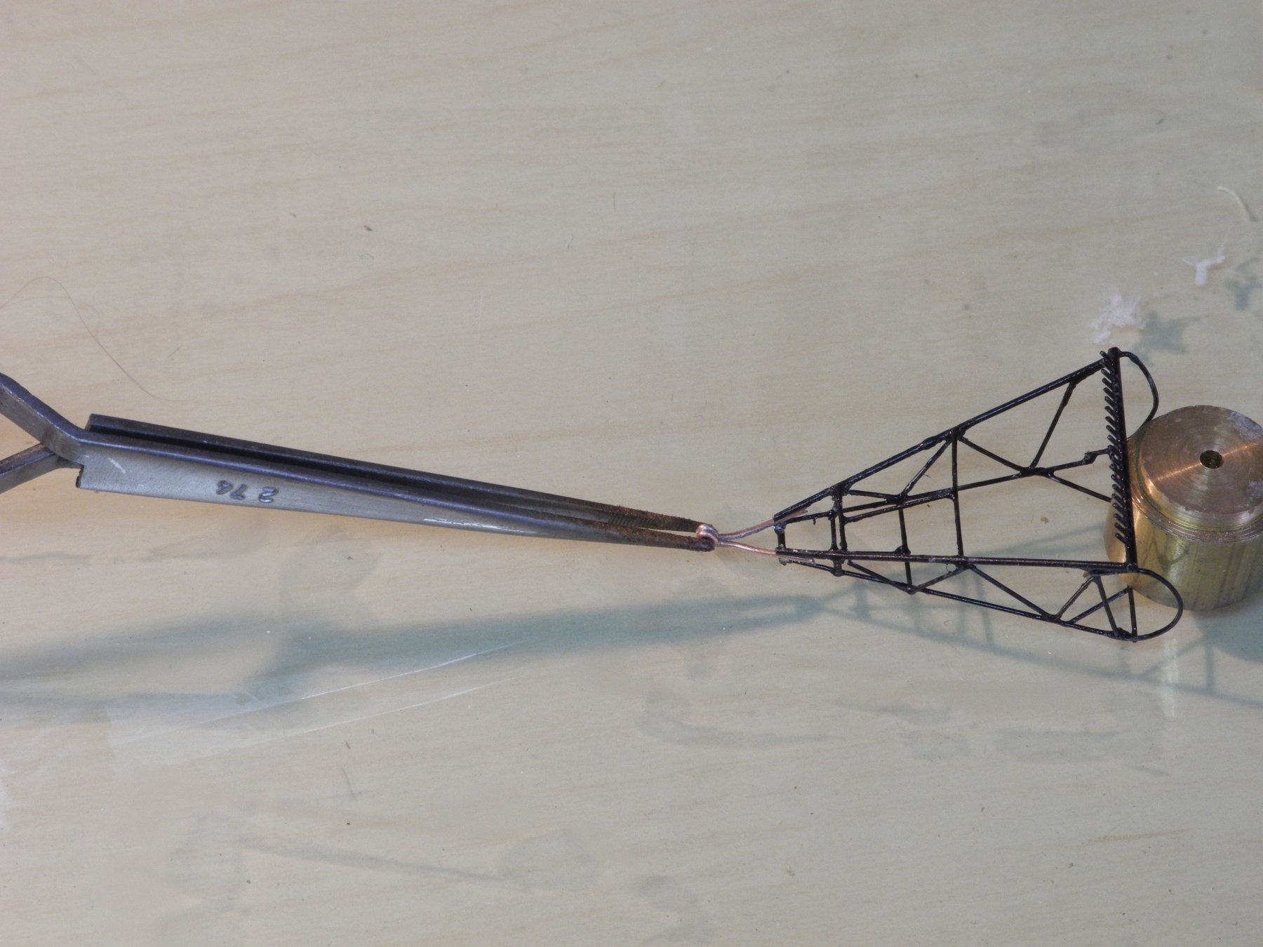
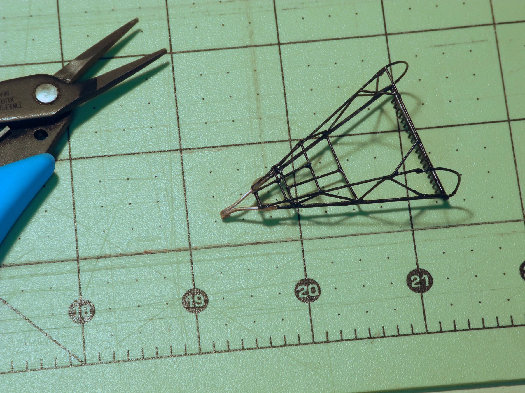
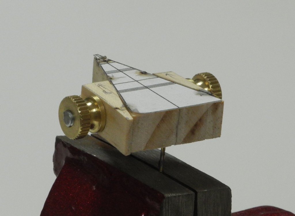
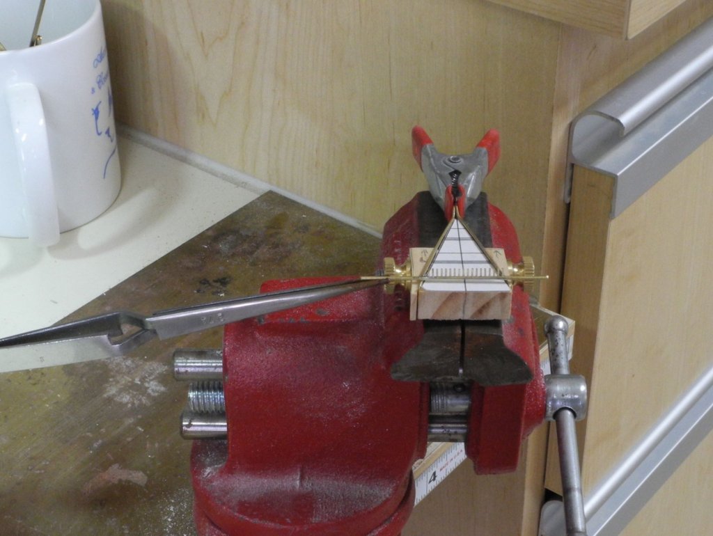
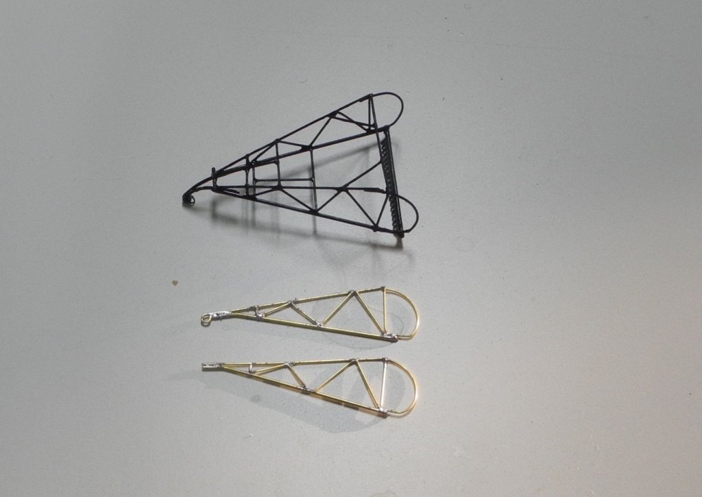
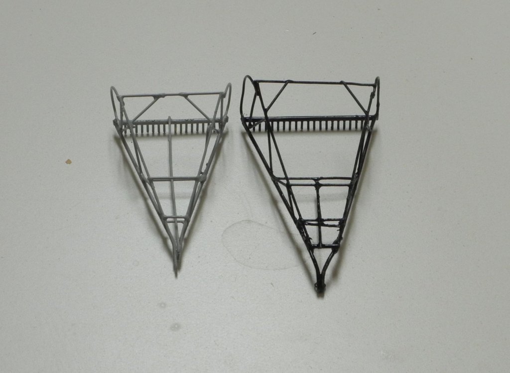
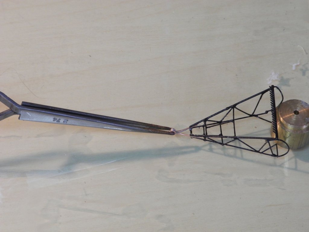
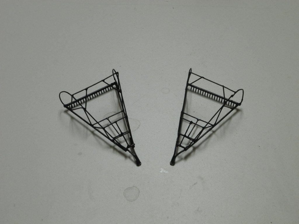
Part 102 –Oyster Dredge Cont’d Hi Everyone It’s been about a month since my last update. We had a very enjoyable vacation, then shortly after we got home some unexpected company showed up. So there hasn’t been very much shop time lately. After my last update I tried out the dredges on Kathryn’s deck, and discovered that they are slightly too large. They look ok hanging off the side, but I want to display one on the deck and one off the side, over the roller. So, after a lot of thought I decided to build new dredge frames that are reduced by about 15%. Because of the issues that I previously ran into regarding holding the pieces while soldering, I decided to make a jig that gave me a lot more control. The wedge shaped main body of the jig is drilled to take a 6-32 threaded rod, and two smaller wedges slide over this rod to hold the two sides in place. A pair of 3/64 brass rods are inserted in the bottom of the main body so that it can be held in the vise. This new jig provided a much more stable base for soldering the dredge body together. Following is a photo of the dredge ready for soldering. The rod with the tines, or teeth, is held in place by a third hand. In this latest pair of dredges I planned for the apex (front of the dredge) before assembling the dredge. The next photo shows the sides for the new dredge, with the apex extension already formed. The final photo shows a new dredge next to the previous version. I’m happy to report that the new dredges are a good size, and look good on the deck. Now for the final part of the dredge construction, making the ring and rope net.


- 878 replies
-
- 18
-
-
Hi everyone. Thanks for following my work on Kathryn, and for all of the encouraging 'Likes' and comments. I haven't been able to get in any shop time since the last post - too many things needed to be wrapped up before our planned vacation. We'll be leaving on our trip tomorrow, and won't be back for a few weeks. I won't be able to post any updates until the end of the month. We'll be staying in a nice condo and plan to spend a lot of quiet time, so while we're away I'm hoping to start drafting the plans for my next build. If that works out I may start a new topic to cover that. In the meantime, I hope you all enjoy a healthy and happy June 2019.
-
Thanks Carl. I'm not sure I would have been able to get the dredges completed without using Resistance Soldering and a very low temperature solder. That combination allowed me to solder very close to existing joints without disturbing them too much.
-
Thanks Mark. The details are a result of the excellent reference material I've been lucky to have, plus access to some folks who really know the Chesapeake watercraft. Thanks Ed. It has been a fun journey and a great learning experience.
-
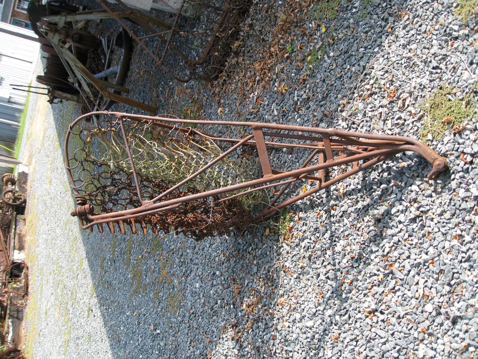
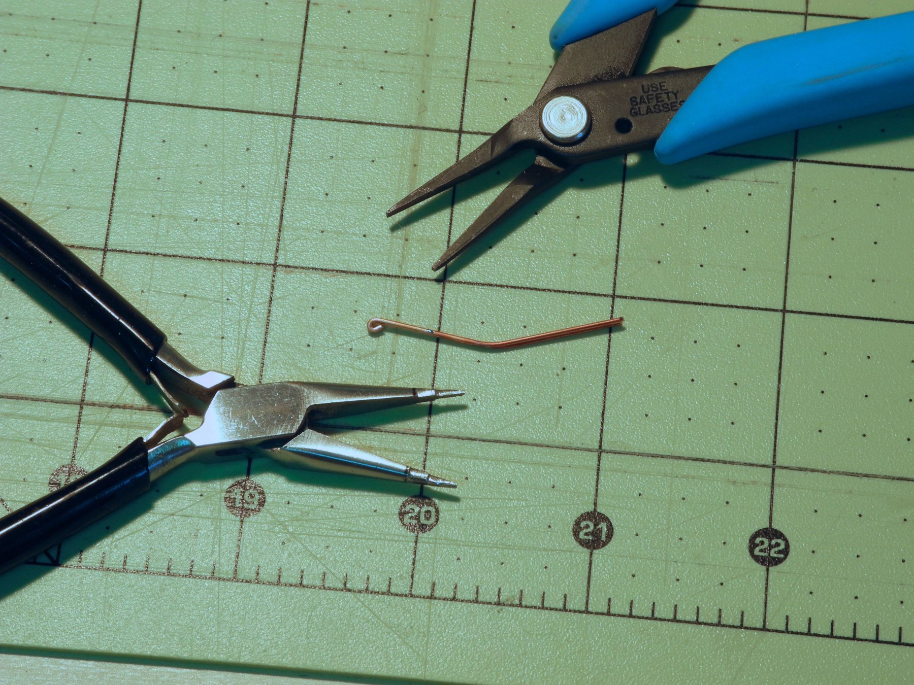
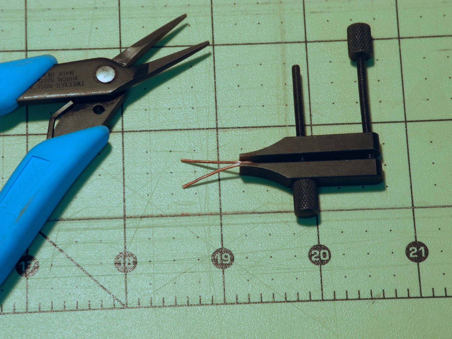
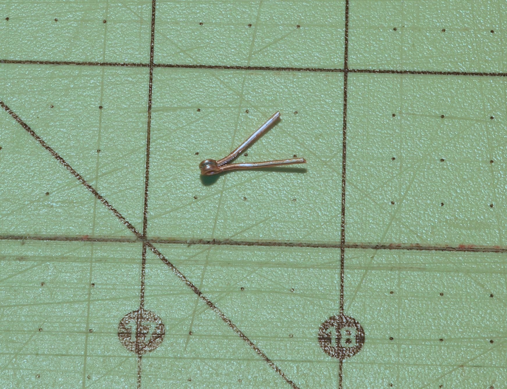
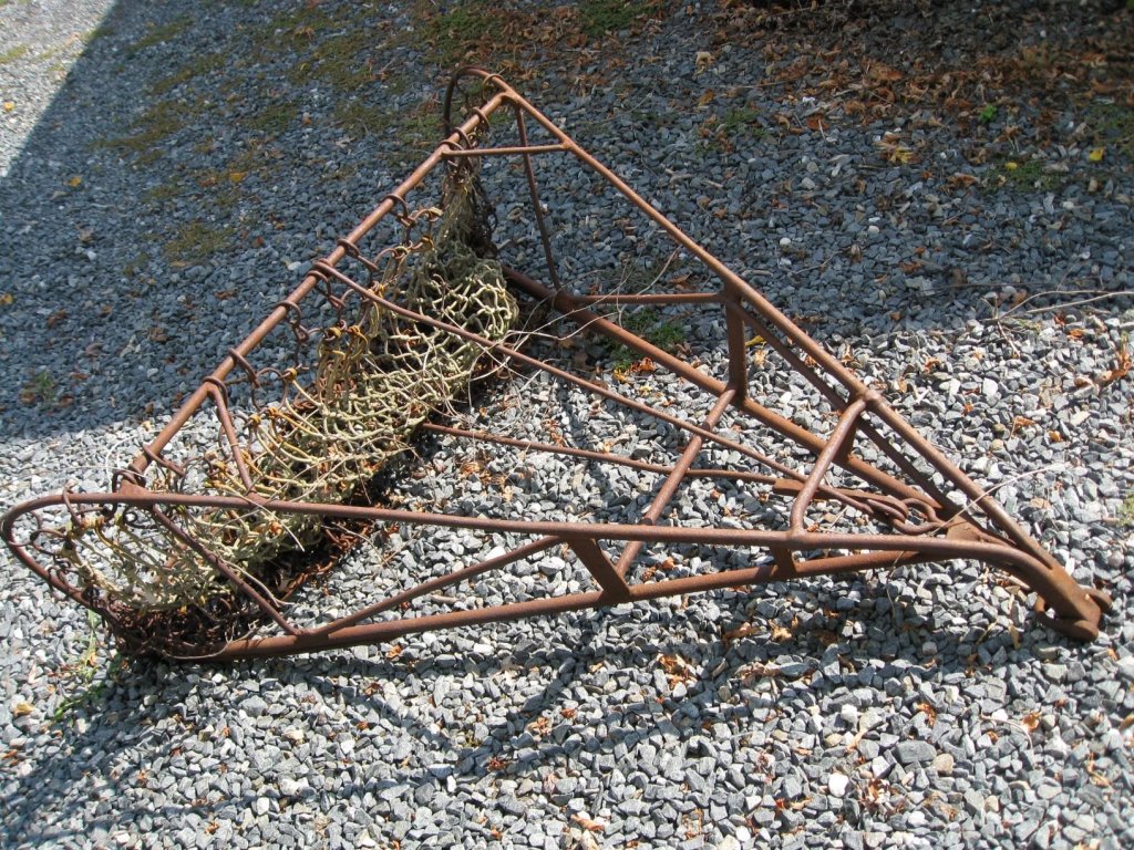
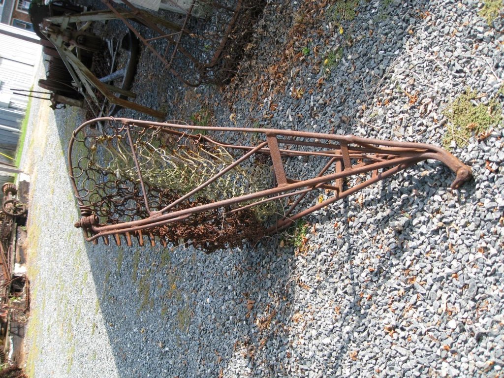
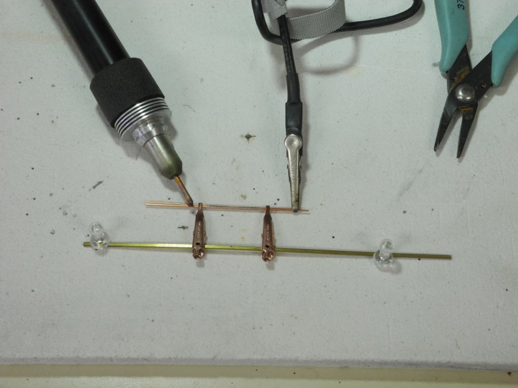
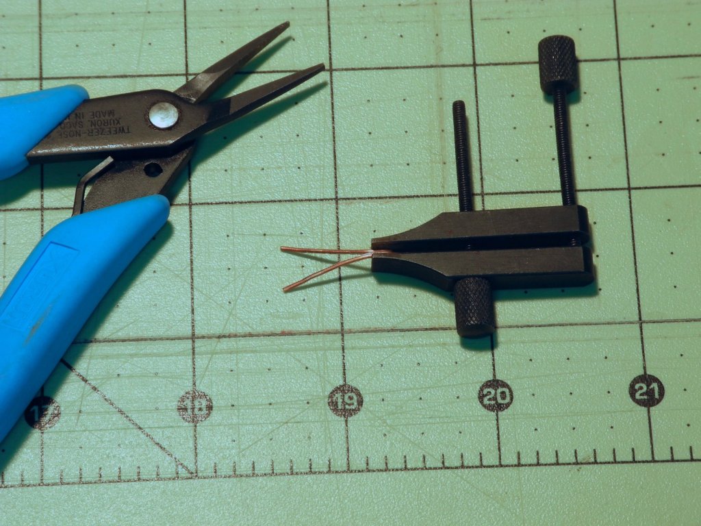
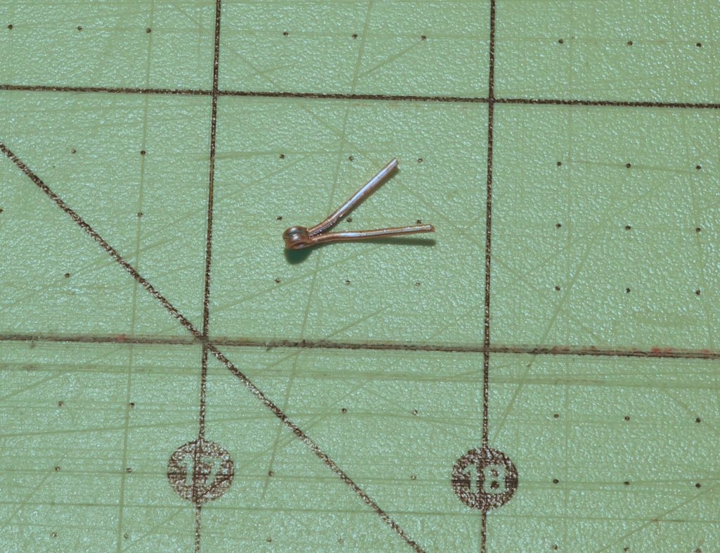
Part 100 –Oyster Dredge Cont’d I sent photos of the dredges to a good friend in the Chesapeake area. He’s an excellent modeler with extensive knowledge of the Chesapeake workboats, and he was quick to point out that the ‘apex’ (nose?) of my dredges was wrong. He sent along the following photos of an actual dredge. So obviously I needed to correct this. I started by soldering two straightened pieces of 24 gauge copper wire together. I used the soft solder with the following setup. I cut the resulting piece in two, so that there was enough material for both dredges. One end of the piece was formed into a round eye – this will take the ring that is used for the dredge cable. The eye was formed by wrapping the wire around the jaws of a small pliers that was shaped for making rings, and then was tightened using small straight pliers. The eye of the workpiece was clamped by a small machinist clamp, and then the arms of the workpiece were pulled apart - easily done because of using a soft solder. This made the shape of the apex for the dredge. The apex was epoxied to the dredge body, using two-part epoxy that had been mixed with talcum to prevent the epoxy from spreading too much. The front of the dredge was primed and painted. Now, back to work on the nets. Cheers!


- 878 replies
-
- 21
-