Mahuna
-
Posts
1,504 -
Joined
-
Last visited
Content Type
Profiles
Forums
Gallery
Events
Everything posted by Mahuna
-
 Thanks Ron. They came out pretty well, but as you'll see in the next post they needed some additional work.
 -
Hi Patrick - yeah - I made it look easy in the photos, but it was very frustrating to say the least. I guess practicing perseverance is good thing, though. Thanks John. I'm glad I'm not working in a smaller scale! Thanks Lou. I'm actually very pleased when I look at any part of Kathryn - a fun build and easy to look at. Thanks Allan. The Sherline Mill made the tines a fairly easy job. Thanks Druxey. The Corian doesn't let solder adhere to it, and resists burning pretty well, especially when using resistance soldering. Thanks John. The wonders of soft solder and a resistance soldering setup. Using a micro torch would have been a different story, I think.
-
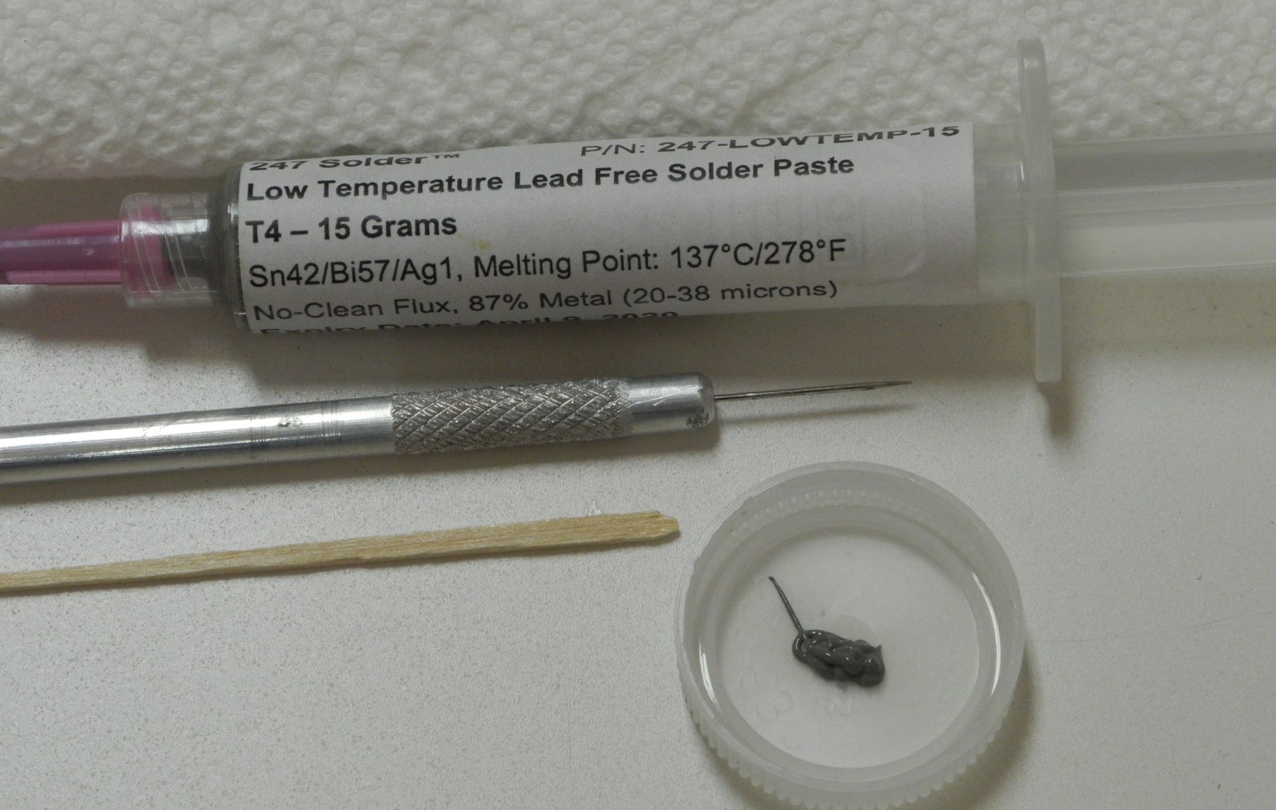
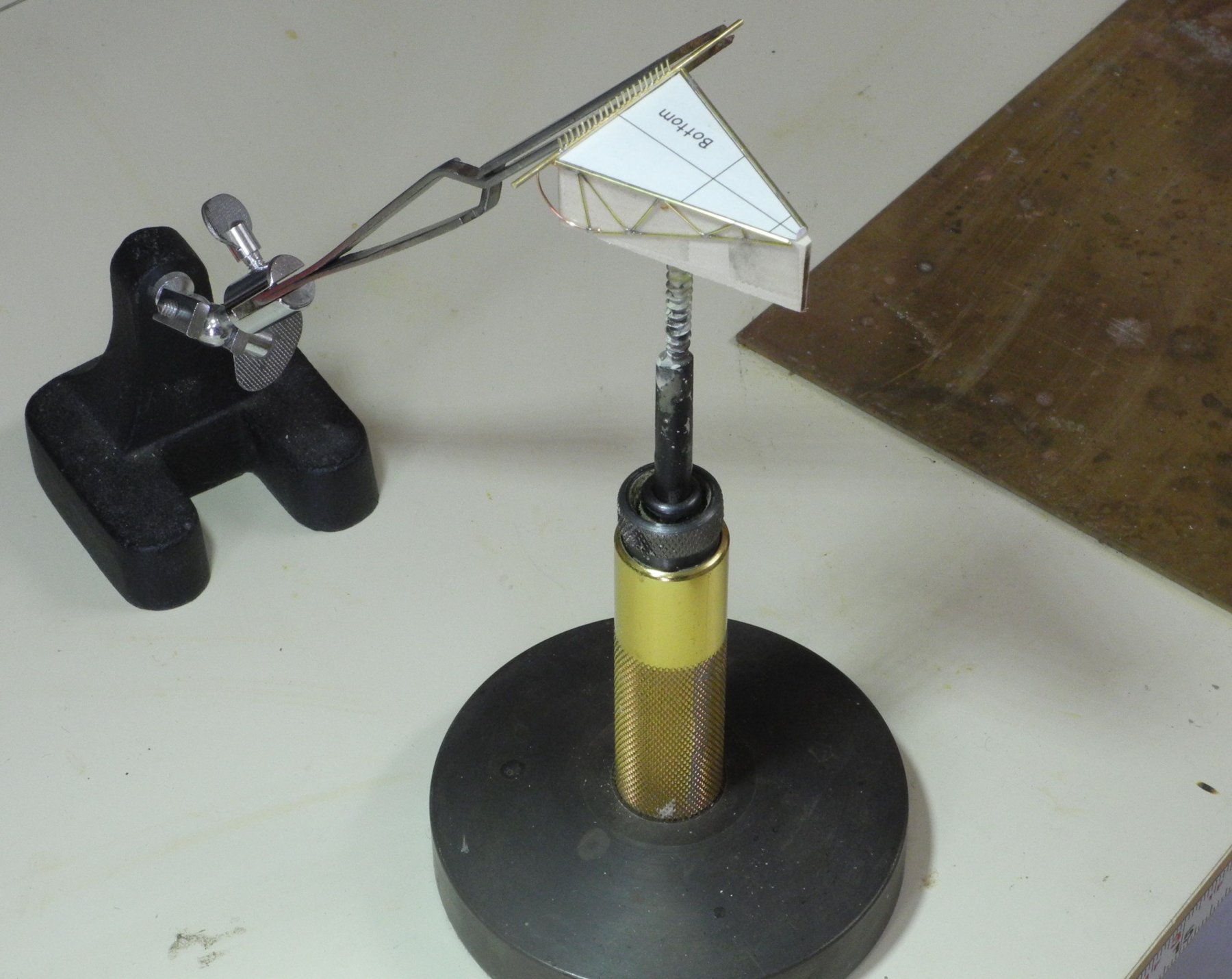
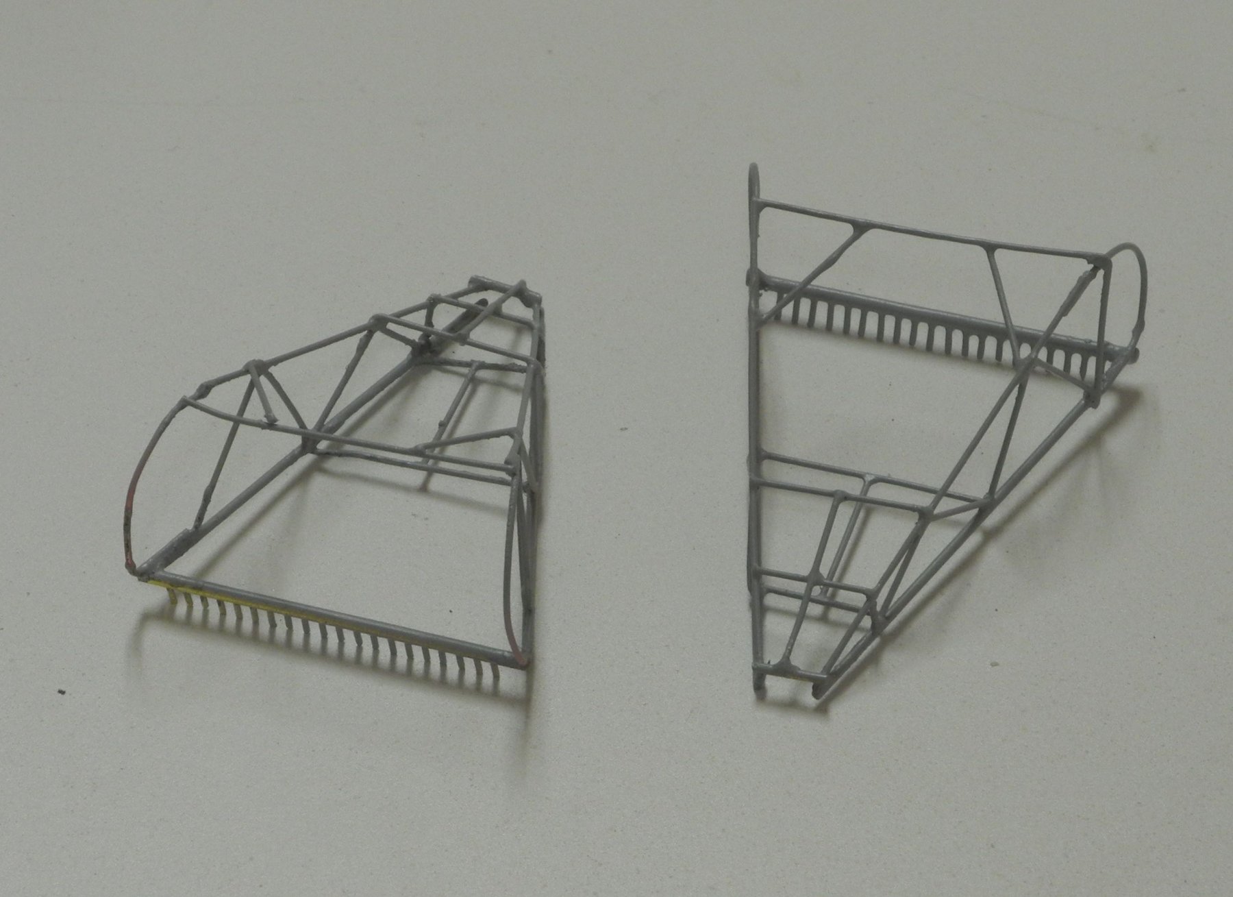
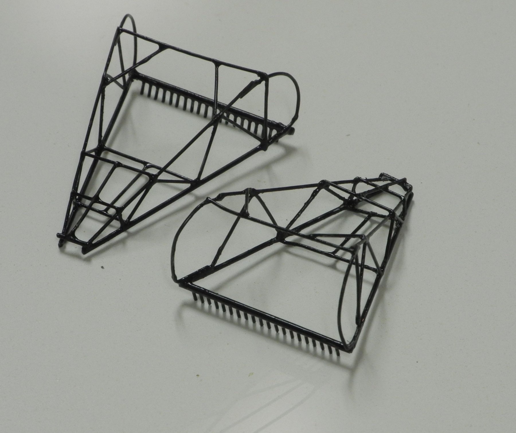
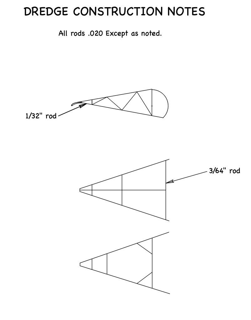
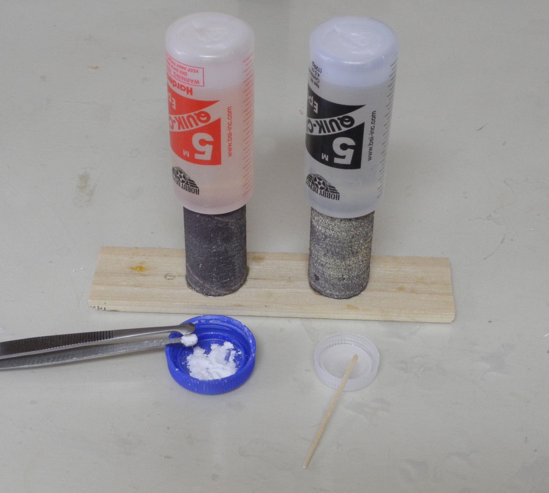
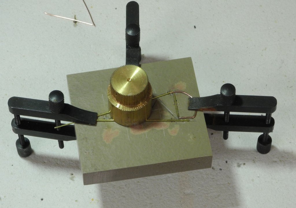
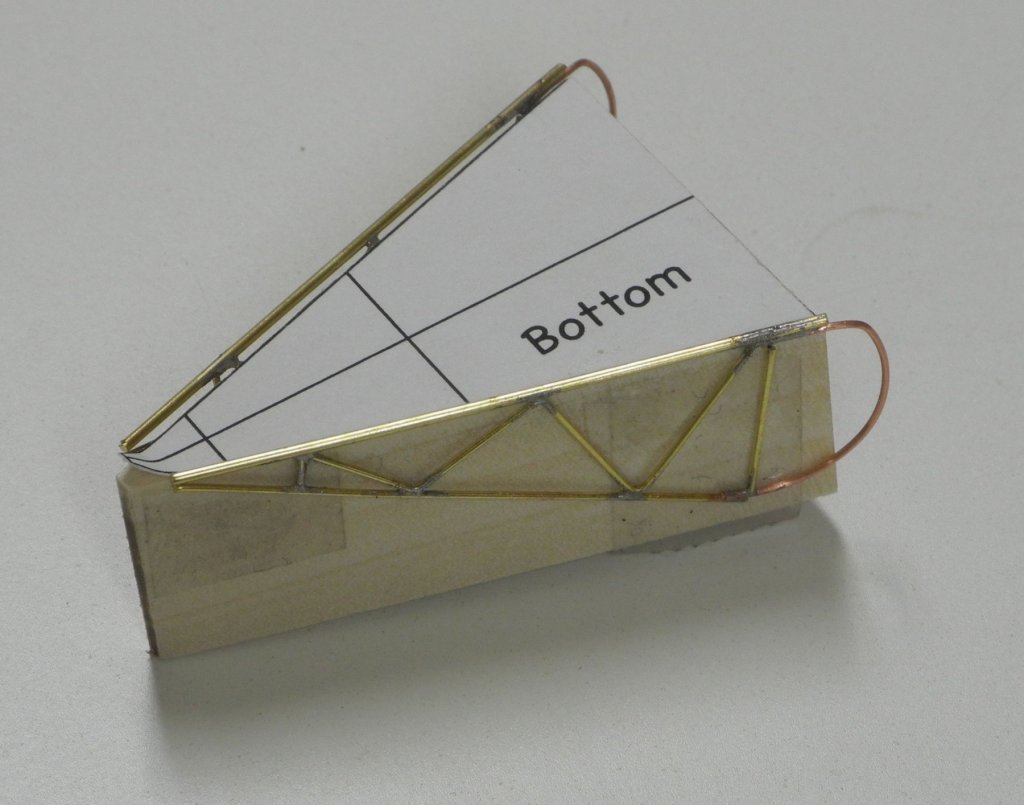
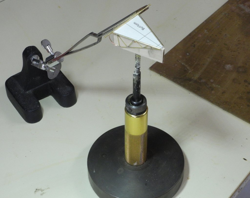
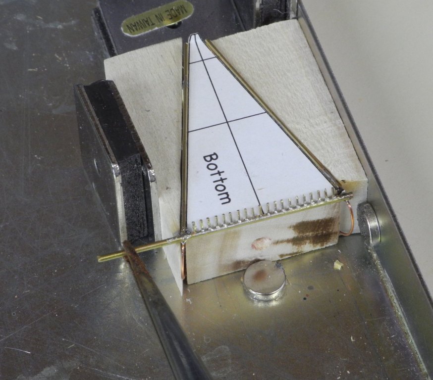
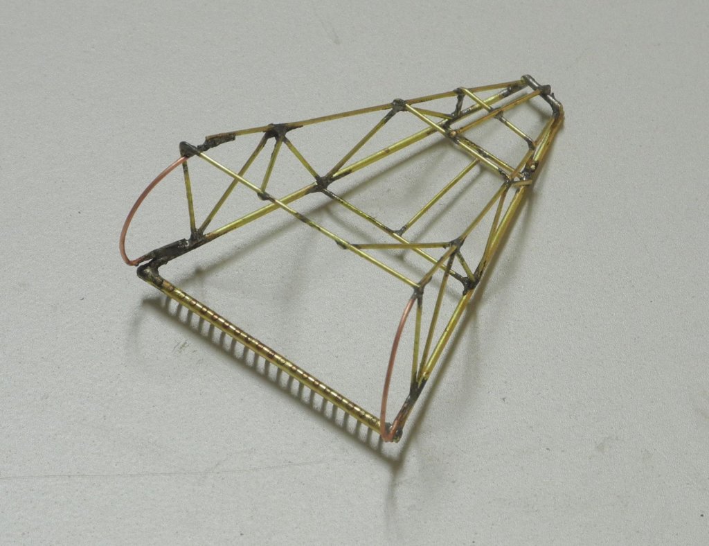
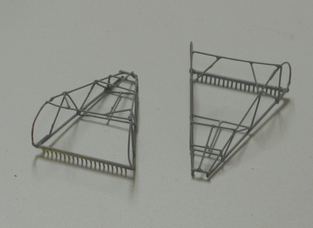
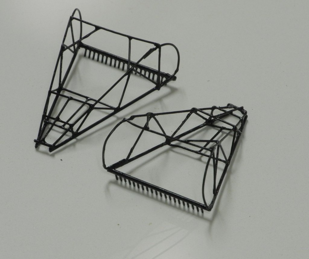
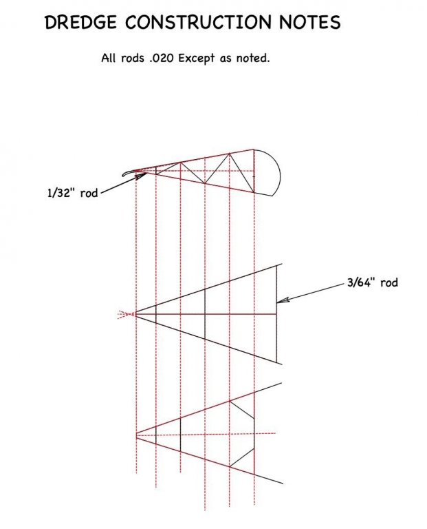
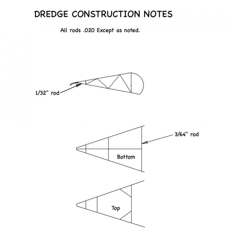
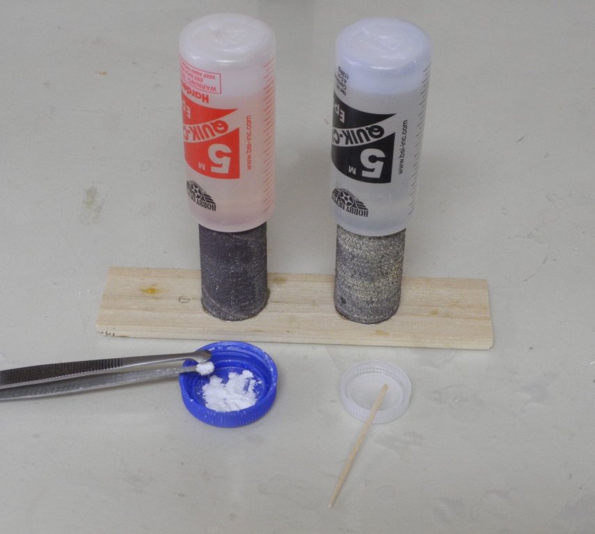
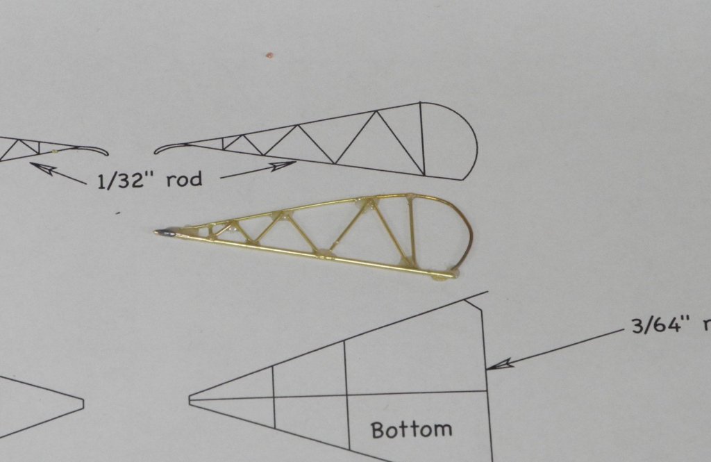
Part 100 –Oyster Dredge Cont’d In a previous post I described the soldering jig that would be used to create the sides of the 2 dredge bodies. The pieces to be soldered were primarily .020” brass rod. In addition, 24 gauge copper wire was used for the rounded ends, 1/32” rod was used for the main structural rod on the sides, and 3/64” rod was used for the tooth bars. Given the small size of most of the pieces, I used a low melting point solder paste. The reason for this choice was to avoid damaging the small pieces with high heat required for other solders. Even so, the heat of soldering did cause some unwanted bending of the thinner pieces. The following photo shows the solder that was used, along with a couple of tools that were used to apply the solder. The side was clamped to the soldering jig using small machinist clamps. These clamps also served as legs to raise the jig. Some of the pieces wanted to raise from the pressure of the clamps, so a small weight was used to keep the pieces on the jig. After the sides were completed they were attached to the former using 2-sided tape. The former needed to be held steady, but the odd shape of the dredges made clamping the former difficult. I tried several approaches for holding the former. First, I tried using a ‘painting stick’ that is designed to screw into the workpiece and had a heavy base. This wasn’t steady enough, and any pressure on the dredge sides loosened the bond of the tape and caused the sides to move out of position. The next arrangement I tried wound up being the one that was used. The former was held in place on a magnetic squaring jig, and wedge-shaped pieces were pressed against the outside to make the whole arrangement square. This wasn’t ideal – the sides still tended to move out of position, but it worked well enough to use it. After a lot of do-overs, frustration, and cussing, the dredge bodies were soldered together. The dredge bodies were cleaned up and primed. And, finally, were painted flat black. So now the ‘easy’ part of dredge construction is over. Next up is the installation of the ring net and rope net to make up the body of the dredge. Thanks everyone!

- 878 replies
-
- 26
-

-
Hi Patrick - that's a great way to display Genesis. It really shows off the radical shape. Well done, my friend! Cheers Frank
-
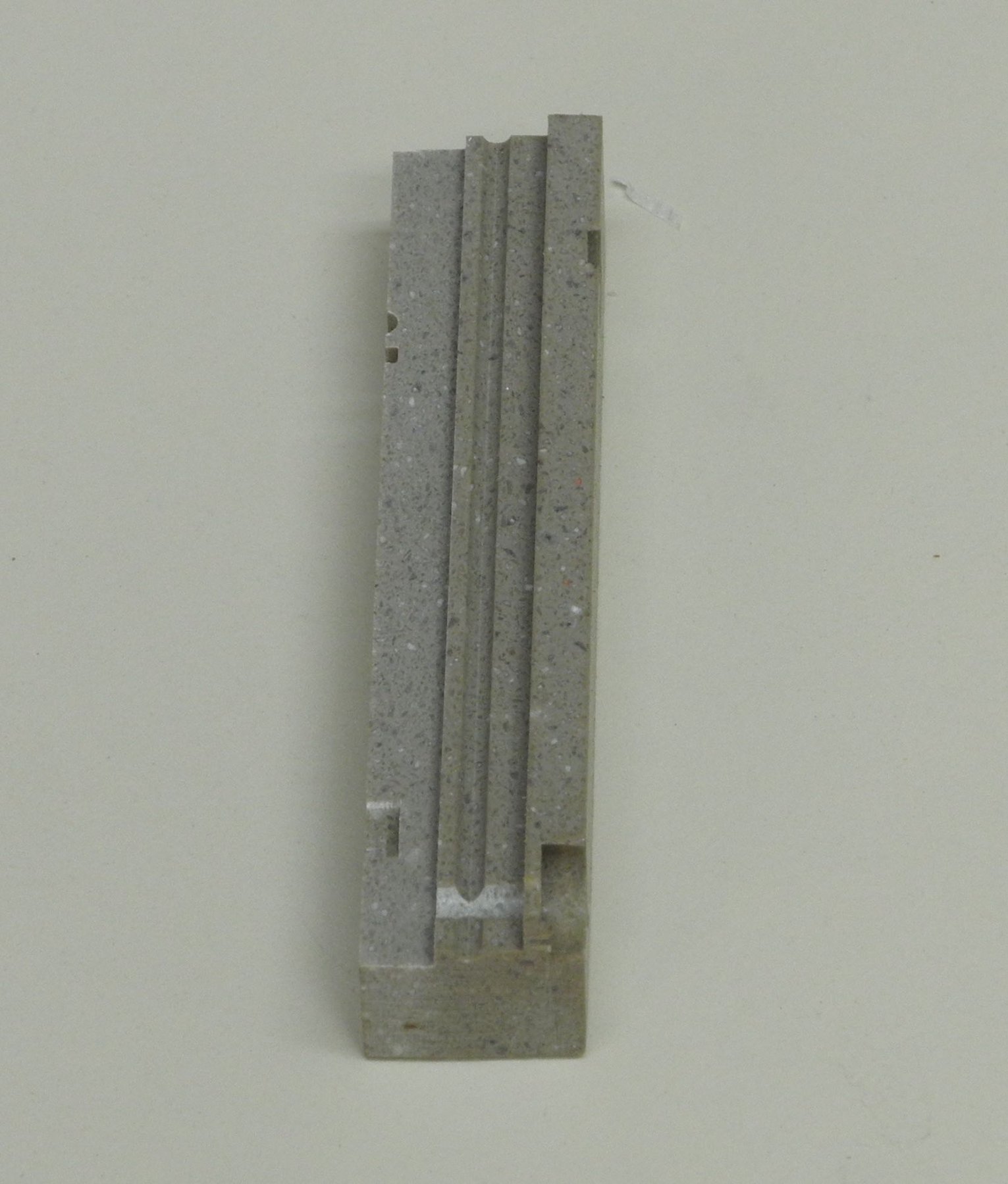
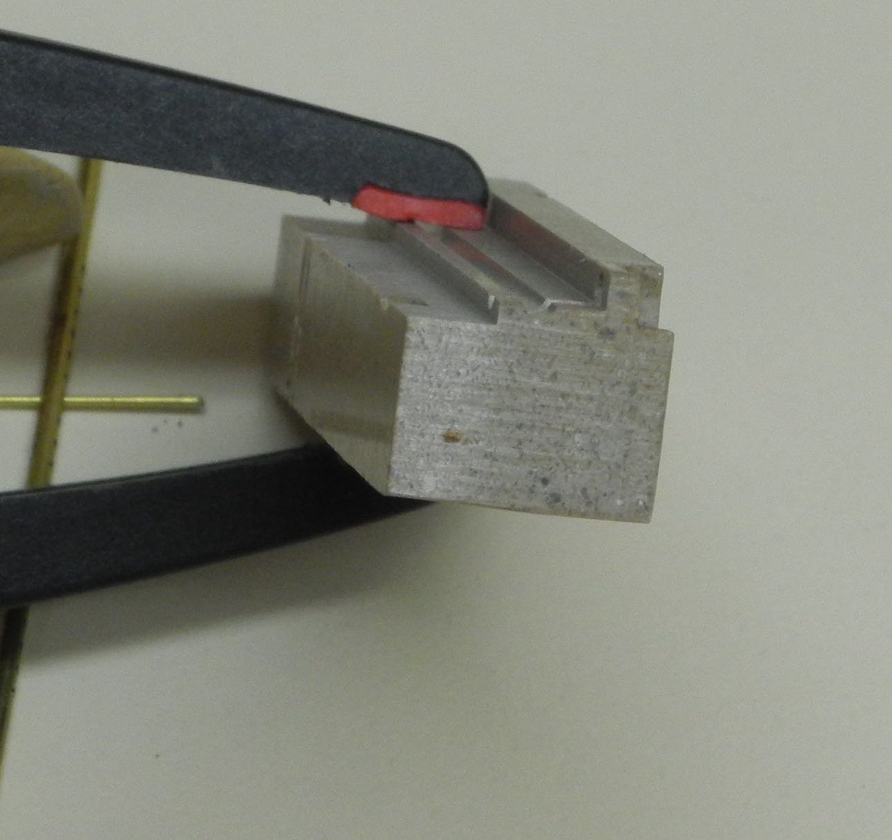
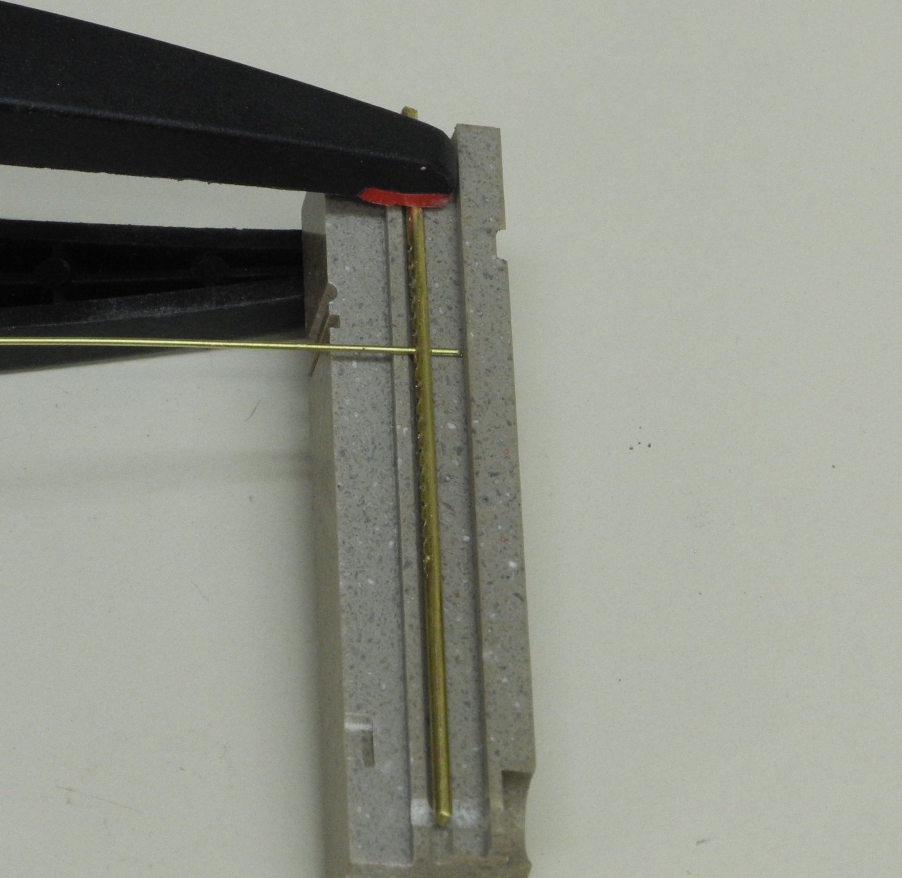
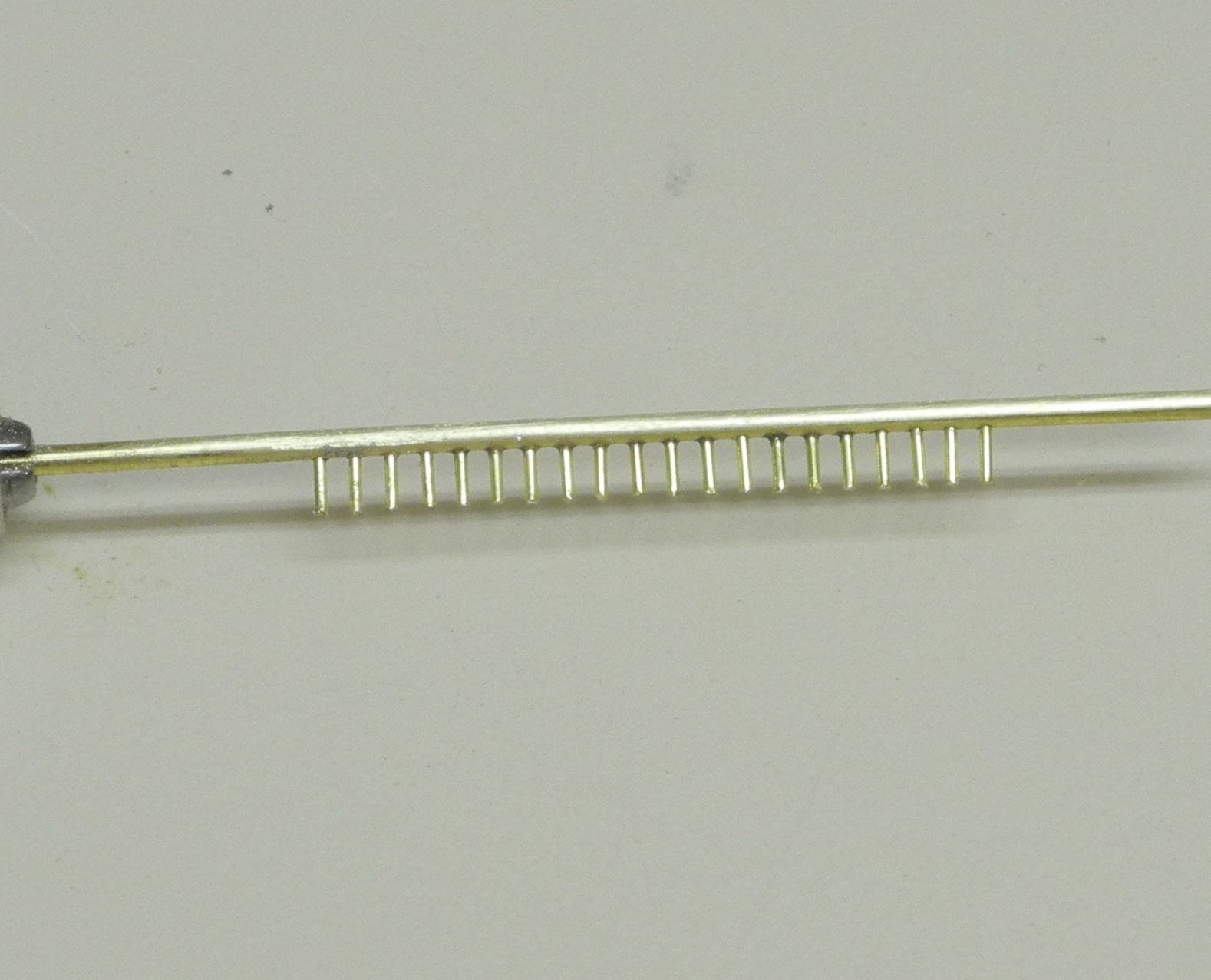
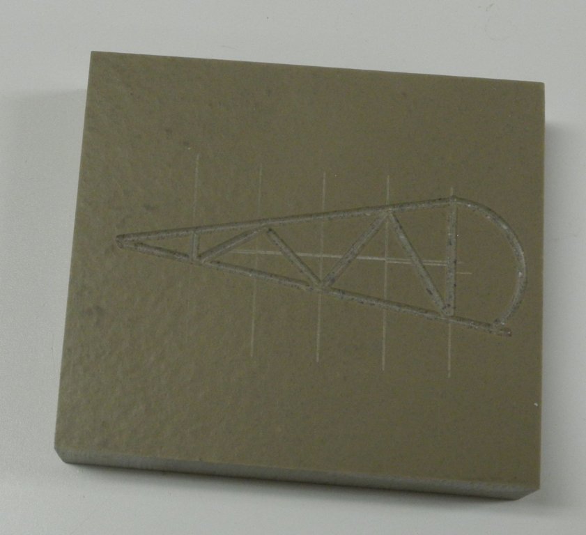
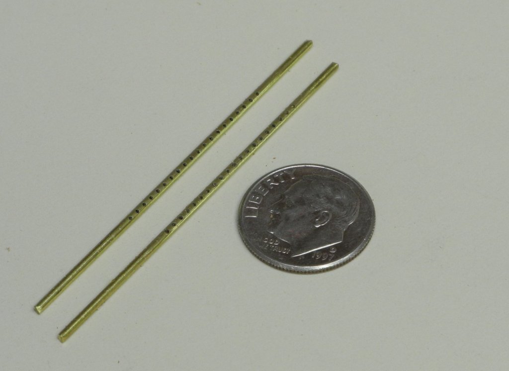
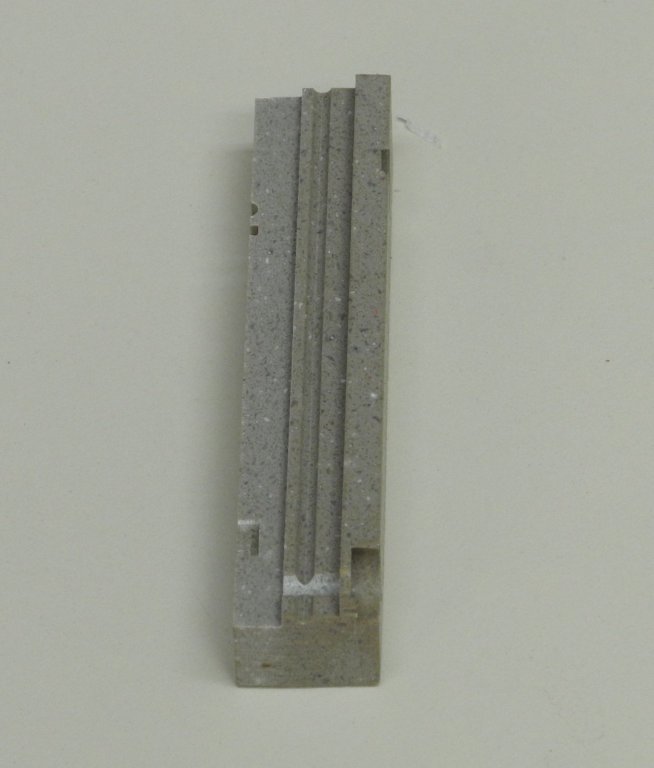
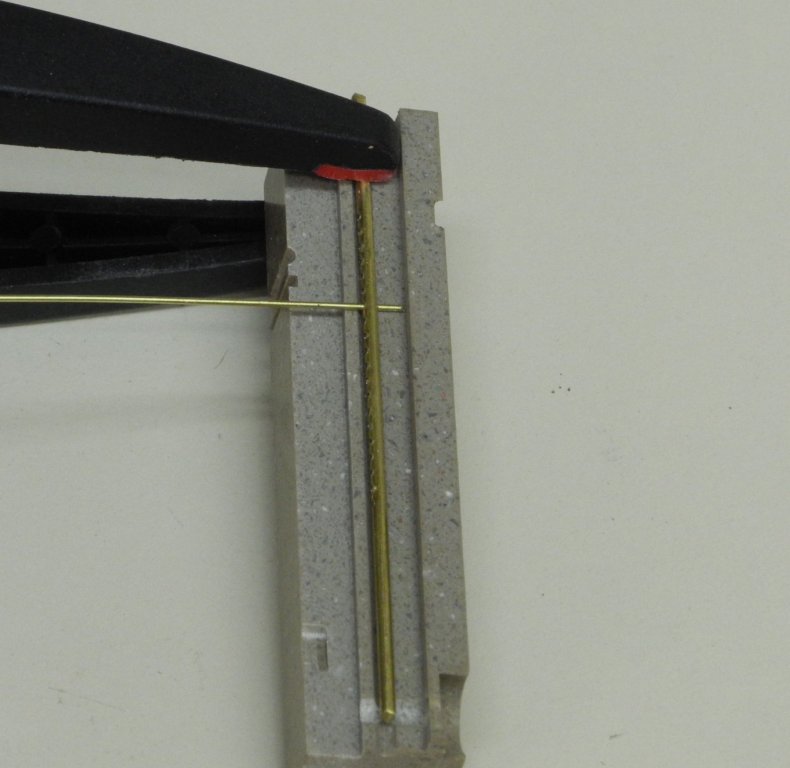
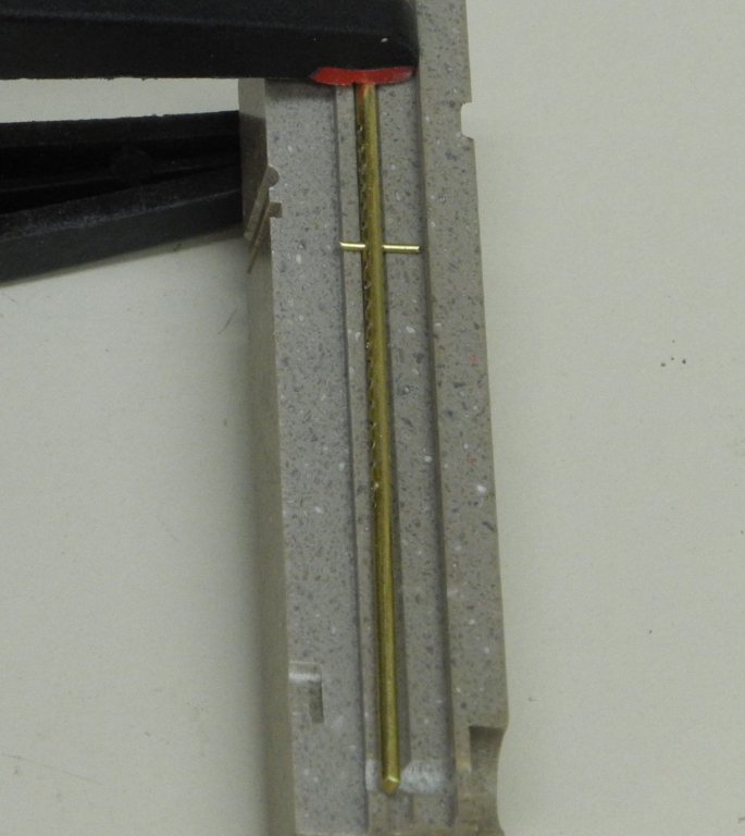
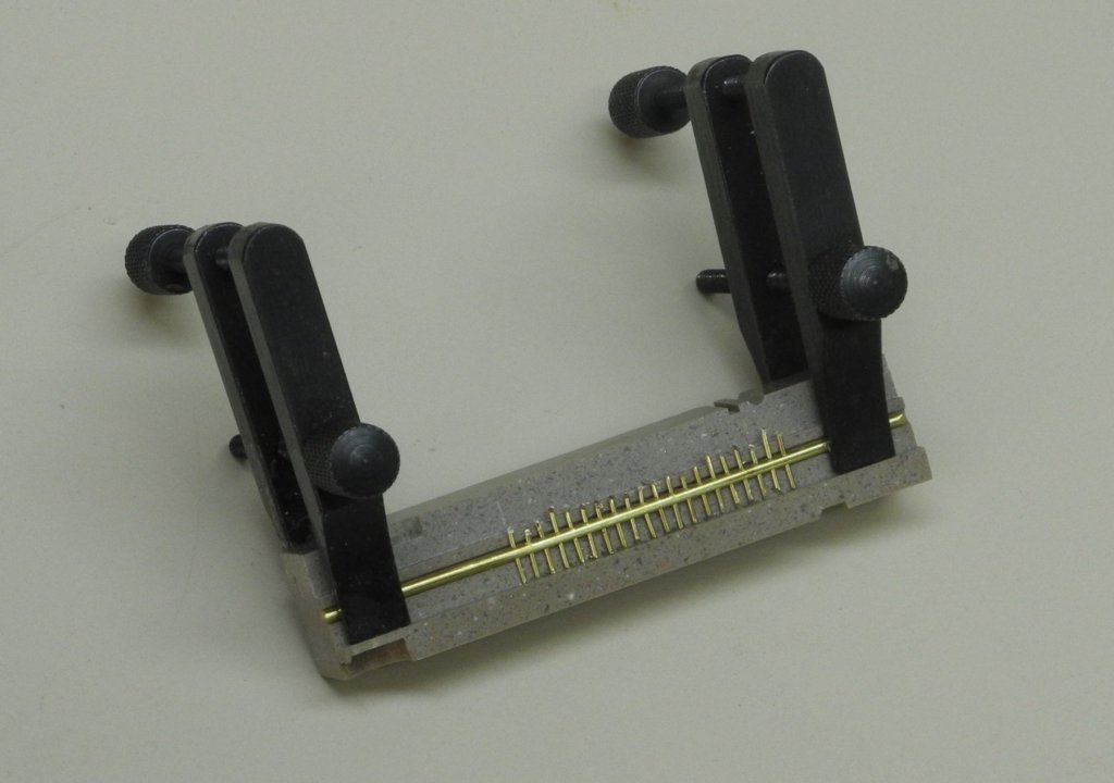
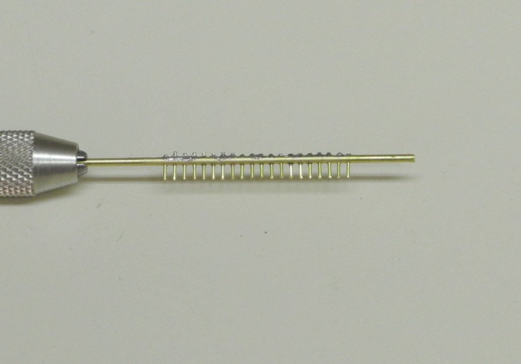
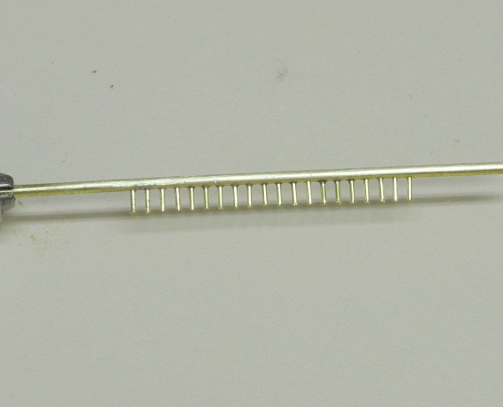
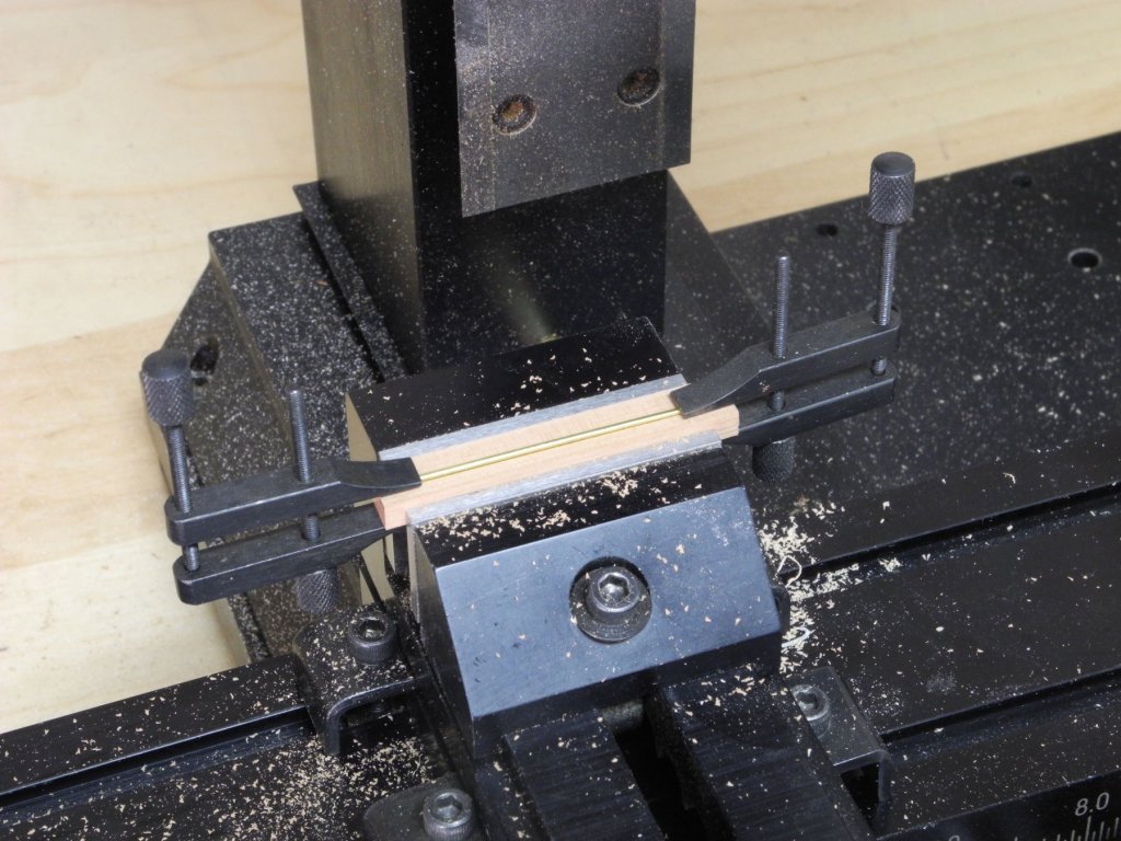
Part 99 –Oyster Dredge Cont’d I haven’t been able to make very much progress on the dredges over the last couple of weeks. Another trip to the Midwest (and more rain) for a high school graduation, then back to Arizona for another graduation, then time spend with out-of-town visitors – all kept me out of the shop. On Monday June 10 we leave for another trip – this time an extended (and much needed) vacation – so I need to focus on the dredges over the next week if I hope to get them completed before leaving. In Part 97 we drilled holes in two pieces of 3/64 rod to create the bars for the toothed bars at the bottom of the dredges. The teeth are approximately 3 inches long (3/32” on the model). I needed to create a jig that would ensure that all of the teeth were a uniform length. The jig was created from Corian because it would be used to hold the workpieces during soldering. The following photo shows the jig that was created. The configuration of the jig can be seen in the following photo of the end of the jig. From the right, the ‘wall’ provides a landing place for the ends of the ‘teeth’. Next to that is a rounded groove for holding the drilled rod. Finally, the lower level on the left provides room for cutting the waste end of the ‘tooth’ so that the amount of waste is reduced. In use, the drilled bar is held in the groove, and a piece of .020 rod is inserted for a ‘tooth’. The waste end is then cut off with a small cutter. The following photo shows a fully populated tooth bar ready for soldering, held in place by two miniature machinists clamps. After soldering, the waste ends of the teeth are cut close to the bar. The bar is then filed and polished, and ready for installation on the dredge. I’ve been working on the construction of the dredge bodies, and that will be the subject of the next post. Cheers everyone!

- 878 replies
-
- 19
-
-
Thanks Patrick, always great to hear from you. You're right - these could be standalone models. Finally making some progress on them - an update follows.
-
Hi Patrick - just catching up after being away for a little while. Genesis is stunning - congrats on another awesome model.
-
Congratulations on the completion of this wonderful model. This has been a totally enjoyable 6 year journey, and quite an educational experience for me. Thank you so much for sharing it with us.
- 3,618 replies
-
- 3
-
-
- young america
- clipper
- (and 1 more)
-
Thanks Brian. Hope all is well with you - hope to see you sometime soon. I hadn't heard of that before Druxey, thanks. I did find something called 'Cool Jool' that I mentioned back in post 27 that does a great job in protecting joints. I plan to use it on the dredges.
-
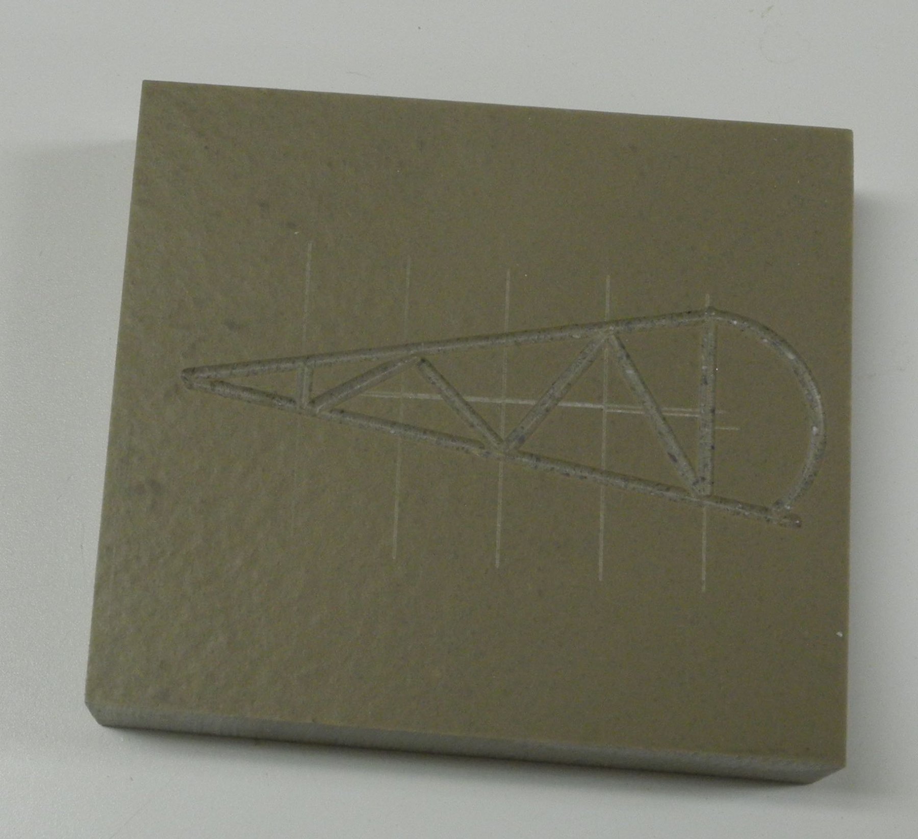
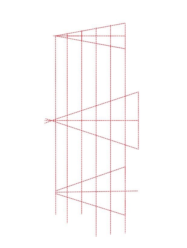
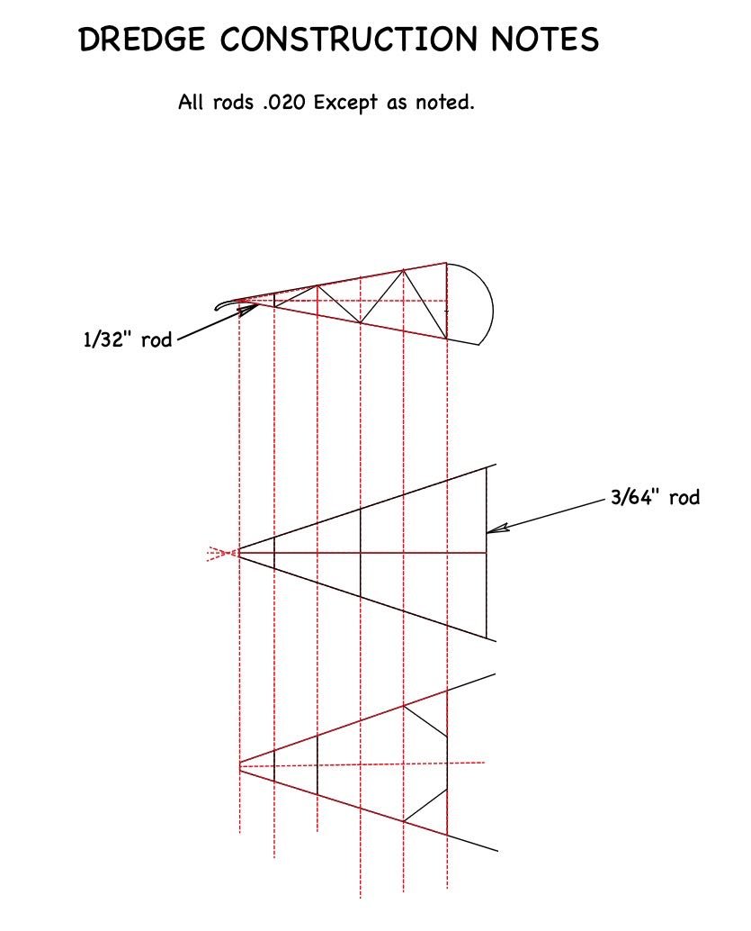
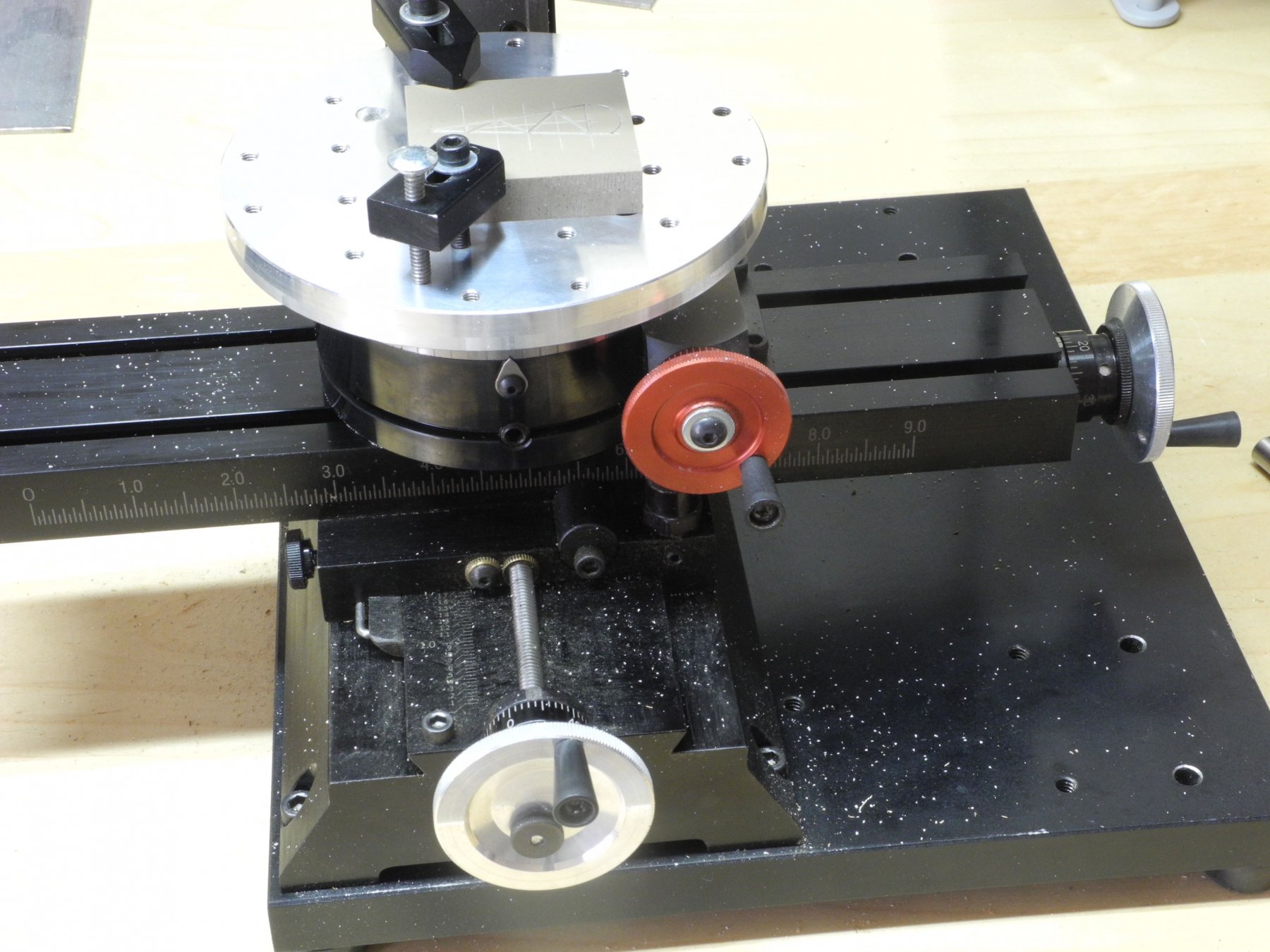
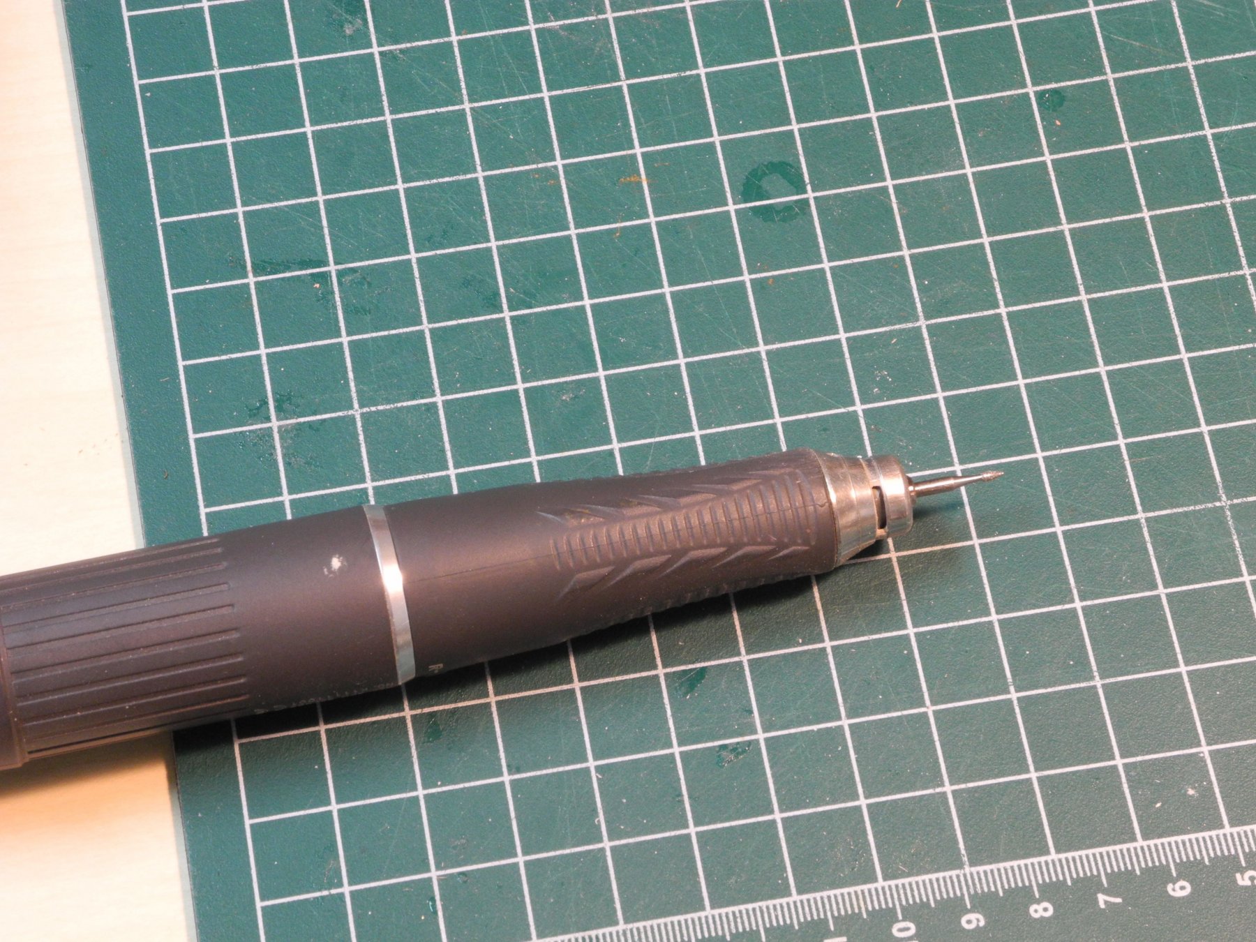
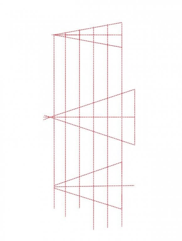
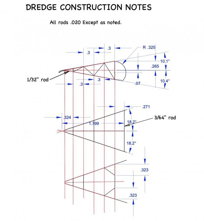
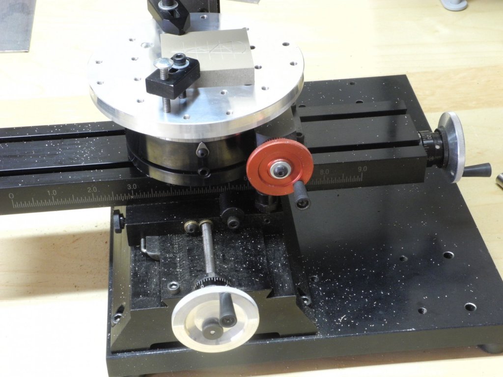
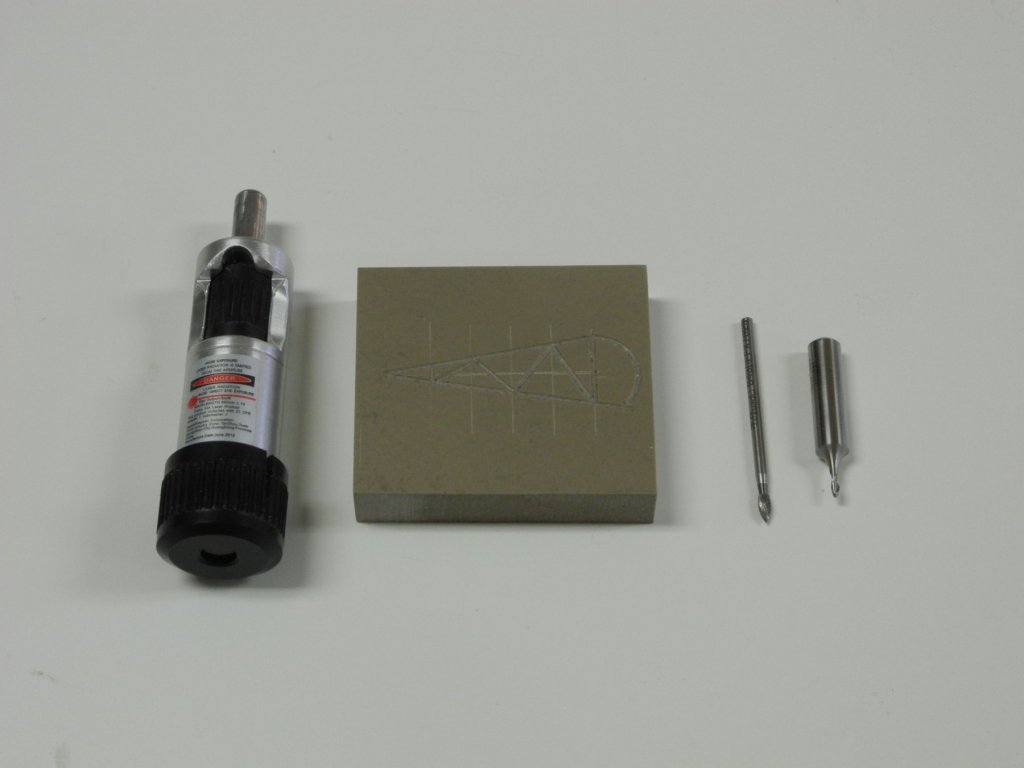
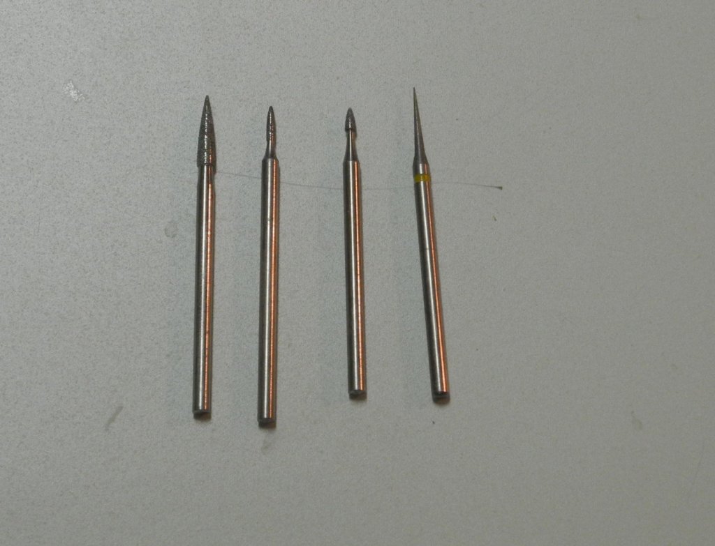
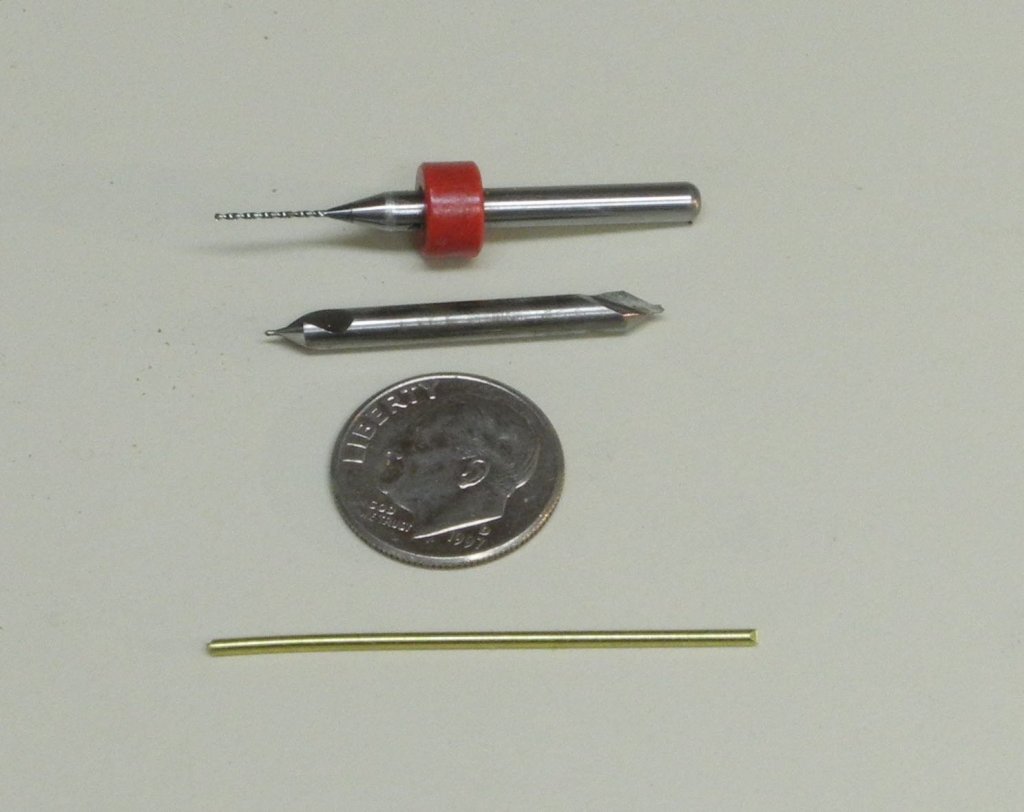
Part 98 –Oyster Dredge Cont’d In preparation for soldering the dredges, I needed to make a jig that would allow me to make two identical sides for each of the two dredges. I used a piece of Corian for the jig, since it resists the heat of soldering and will hopefully serve for all four soldering operations. The dredges were drawn in TurboCAD, using the basic form and dimensions of the dredges shown in the Willie Bennett plans. As mentioned in the previous post, even though Kathryn’s dredges are the same size, the sides of the dredges are configured differently. In drawing the dredge views, I used a series of reference lines to orient the various components of the dredges. In the following photo you can see how the reference lines helped to draw the actual dredge side, top, and bottom views. The various dimensions, including angles, were needed to translate the drawings to the actual milling of the soldering jig. (I used a number of layers to keep the WB drawings, reference lines, dimensions, and final drawings of the Kathryn dredges separate.) For the milling, the workpiece was clamped to the tooling plate on the rotary table. The tools used for making the jig are shown in the following photo. The item on the left is a laser edge finder. This was used multiple times to position and reposition the workpiece and to test whether the planned milling operation would be accurate. On the right of the workpiece, the item closest to the workpiece is a small pointed carbide bit that was used as a ‘scribe’ to draw the principle reference lines that would be used in the milling operations. Finally, the other item is the 1/16” milling cutter with a rounded end that was used to make the grooves in the workpiece. The resulting jig should hopefully work well for soldering the dredge sides. I continue to make the ring nets, and will start the soldering operations in the next day or so. Thanks everyone.


- 878 replies
-
- 17
-
-
Thanks John. I'm lucky to have lots of reference material, so I can make sure the details are (relatively) correct.
-
Thanks Druxey. Yes, I'm sure that soldering will make a stronger dredge. So much for shortcuts! Thanks Rich!
-
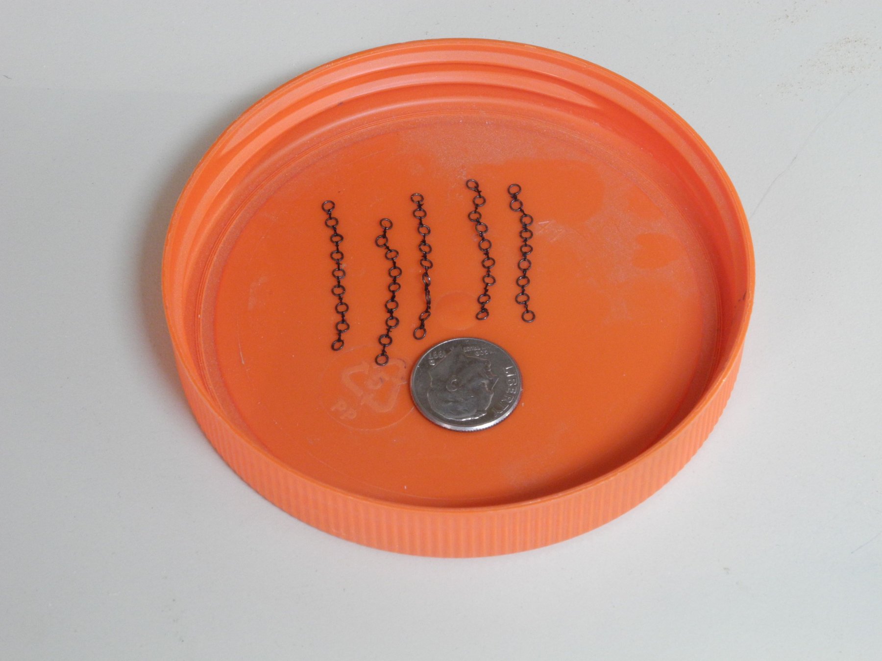
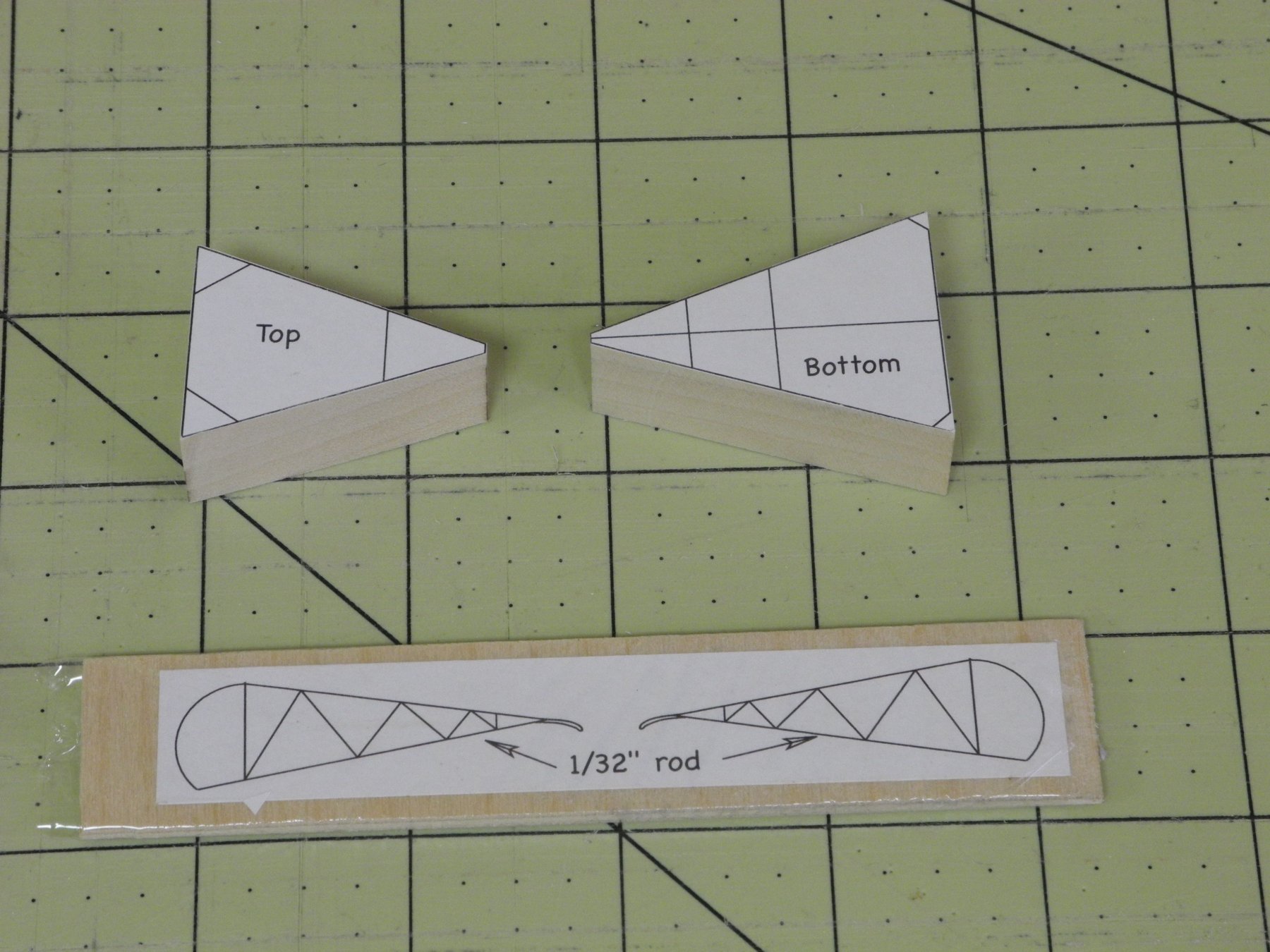
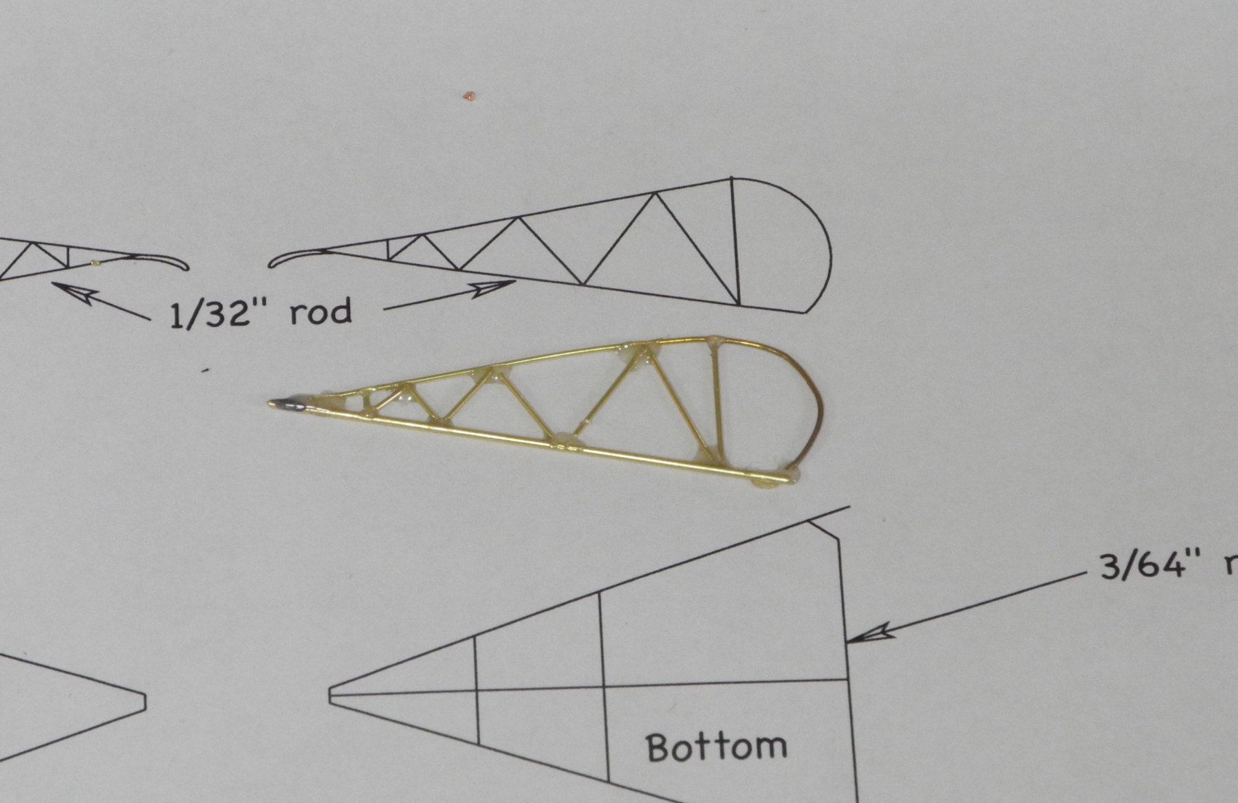
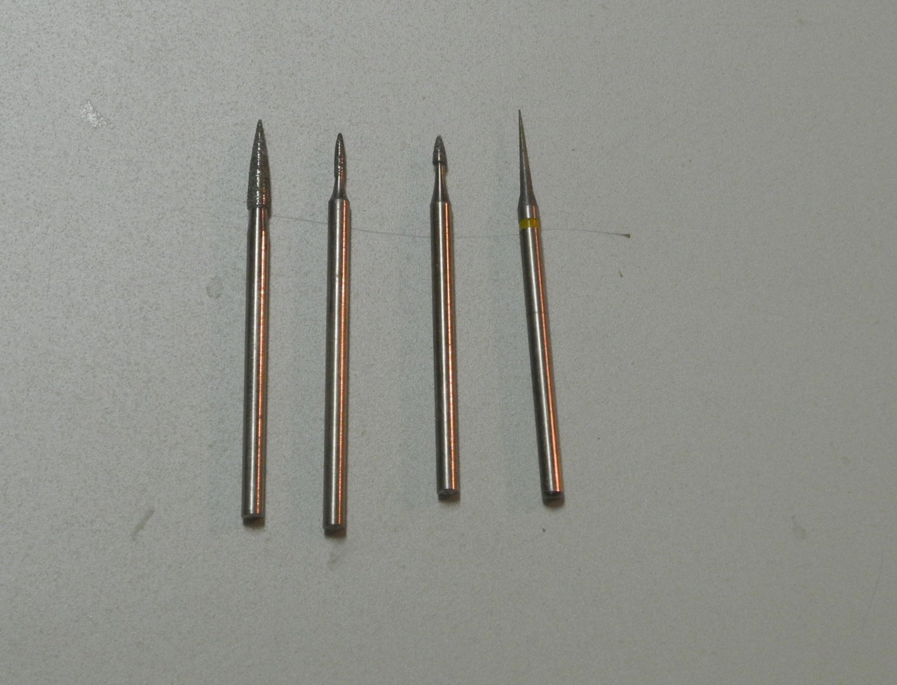
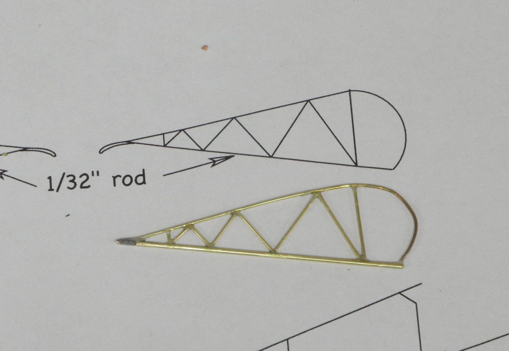
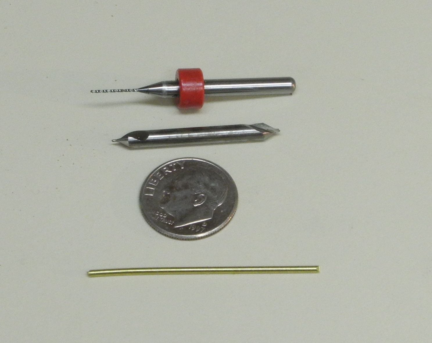
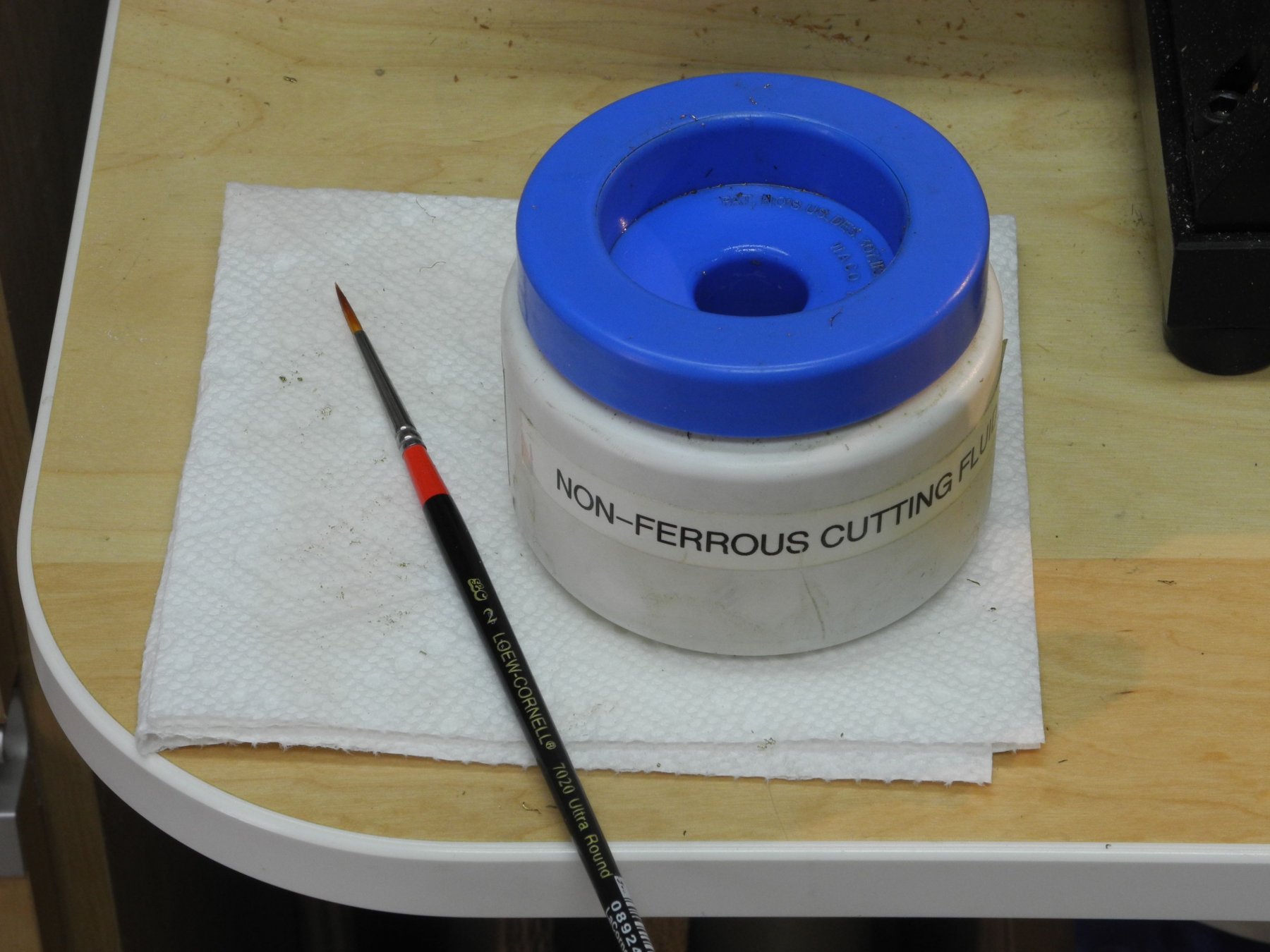
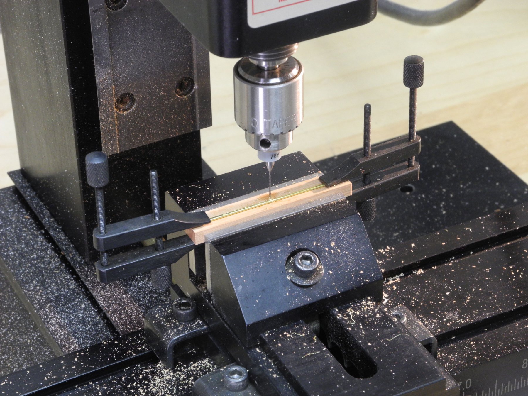
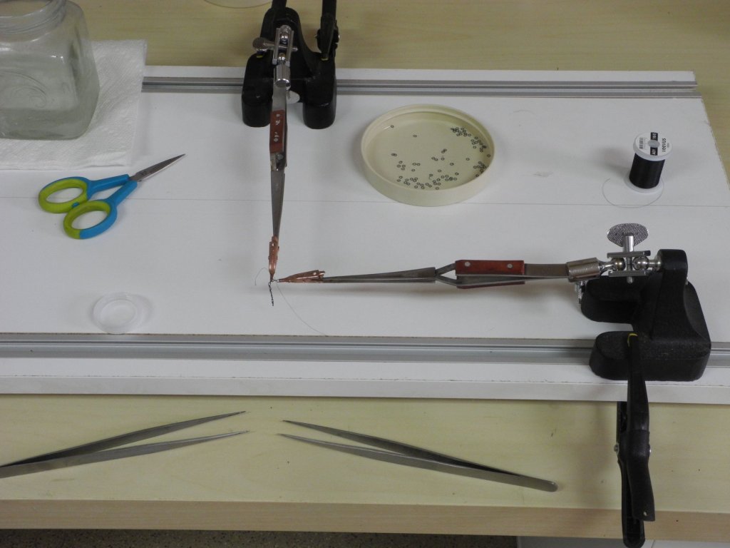
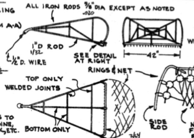
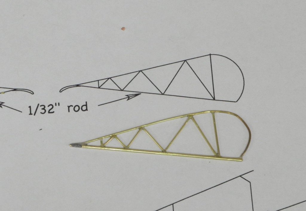
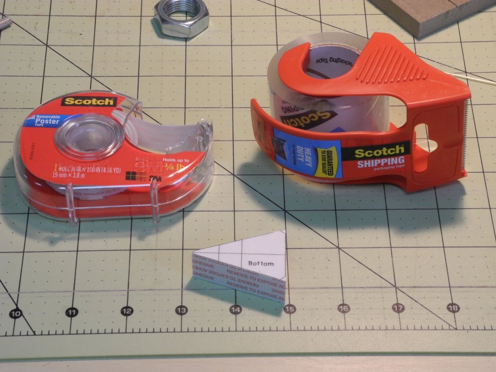
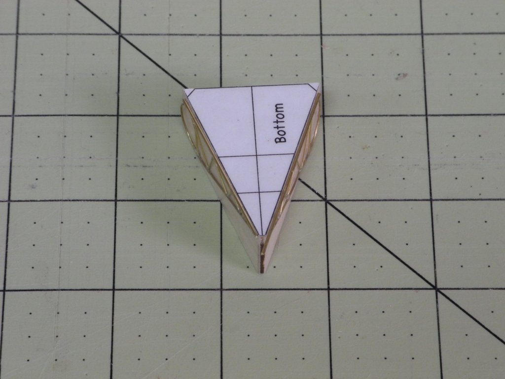
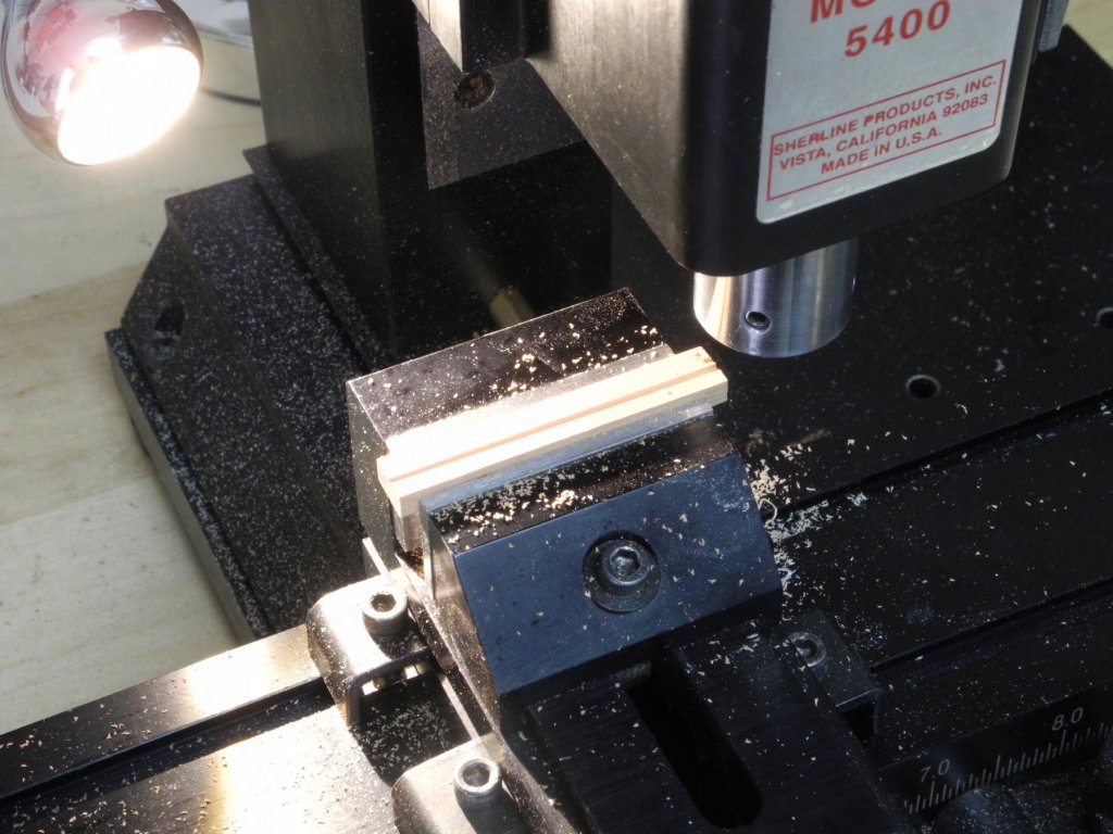
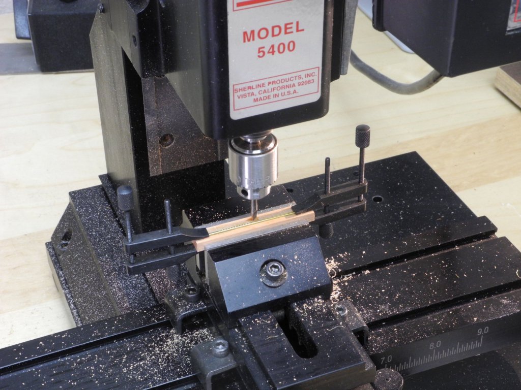
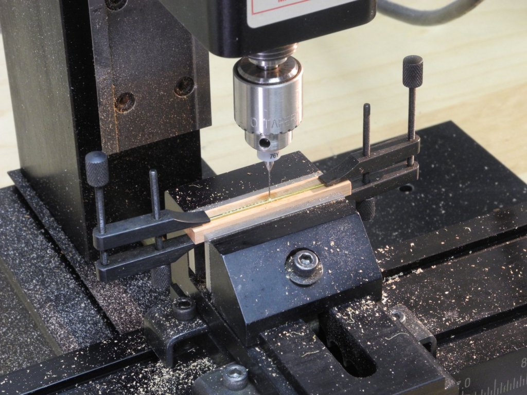
Part 97 –Oyster Dredge Cont’d Work on the dredges was interrupted for a trip to the Midwest (rainy and chilly the whole time). I incorporated some of the valuable suggestions for improving the linked rings. I clamped the third hands to a building board, and positioned the rings at a consistent distance from each other by using a small piece of wood as a spacer. I also make sure the drop of CA is only on the knot – this keeps the chain of rings very flexible and will make the net to be more realistic. The process is still slow – there are now five chains completed. I discovered that the construction of Kathryn’s dredge is quite different from the dredge shown in the plans for the Willie Bennett. The book ‘Working Skipjacks of Deal Island’ has a few photos of Kathryn’s dredges, and using these photos allowed me to design the dredge for the model. Here’s the dredge design for the Willie Bennett: and here’s my drawing for Kathryn’s dredge: I decided to try epoxying the dredge sides together. First step was to paste the drawings onto some pieces of wood to serve as building forms. The drawing of the sides was covered with clear plastic wrap to keep the epoxy from sticking to the paper. I used 5-minute epoxy, and after mixing the two parts together I then stirred in some talcum powder to make the epoxy into a gel-like substance to keep it from running too much. The following photo shows a dredge side after the epoxy had cured. You can see that the epoxy still spread out somewhat and needed to be cleaned up. The clumps of epoxy were reduced using a high-speed rotary tool and some very small diamond bits. The following photo shows the dredge side after it was cleaned up. The next step was to hold the sides to the form for the bottom construction using 2-sided tape. Clear packing tape was applied to the top of the form to keep the epoxy from sticking. I left the sides on the form overnight, and then tried removing them from the tape to see how it worked. It didn’t! The amount of epoxy that needed to be removed for appearance sake left the pieces entirely too fragile and pulling them off the tape caused them to come apart. Lesson learned – I can’t get away from soldering! Another question I’ve been dealing with is how to make the toothed bar for the bottom of the dredge. I decided to see if I could drill a series of holes in the 3/64” rod that will make this bar, so that the teeth could then be set into the holes. I mounted a small piece of wood in the milling vise, and milled a small groove in the wood using a 1/16” milling cutter that has a rounded end. This gave me a very shallow groove to hold the 3/64” rod using small machinist clamps. Drilling was performed using a 00 center drill and a #74 carbide drill. A very important part of the process was to use cutting fluid on both drills. Failing to use cutting fluid will cause the carbide drills to break (just don’t ask me how I know this). The fluid is applied using a very soft artists brush to protect the delicate drill bit. The hole was started using the center drill And was then finished using the #74 carbide drill. The workpiece was advanced .055” and the next hole was drilled. Each toothed bar will have 20 teeth. So the work on the dredges continues. I’ll need to make a soldering jig so that another set of dredge sides can be made. And the tedious work of making the net of rings will continue. Thanks everyone for the ‘likes’ and comments.


- 878 replies
-
- 19
-
-
Nice additions Patrick. It's easy to forget the scale you're working in until the giant thumbnail shows up in one of the photos.
-
Hi John. I’m on a trip to the Midwest right now, so haven’t done any work on the dredges for the past few days. I do intend to make the bags using the rings and rope nets, and have continued the tedious work of joining the rings. I’ve also started making the frames for the dredges, and need to come up with a method for making the bottom bar that has the teeth in it. These little dredges have become a project in themselves. I’ll be posting some progress when I get home later this week.
-
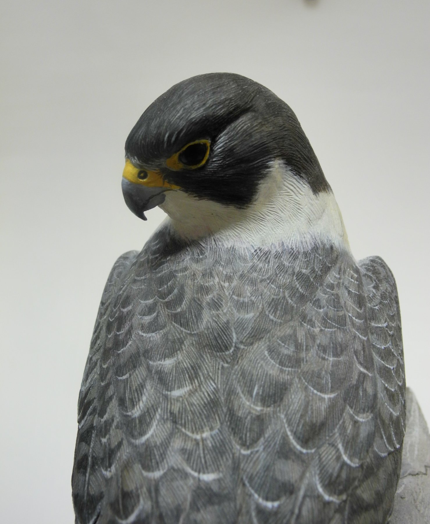
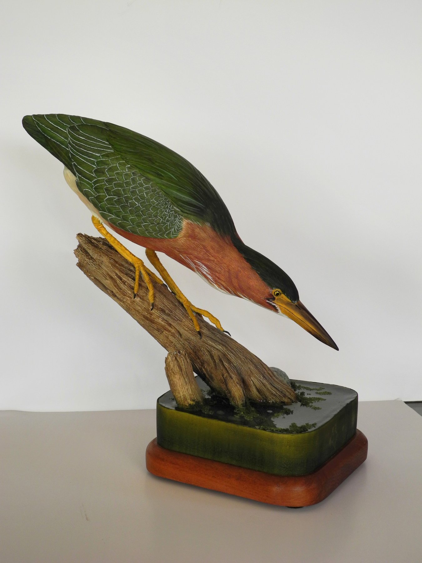
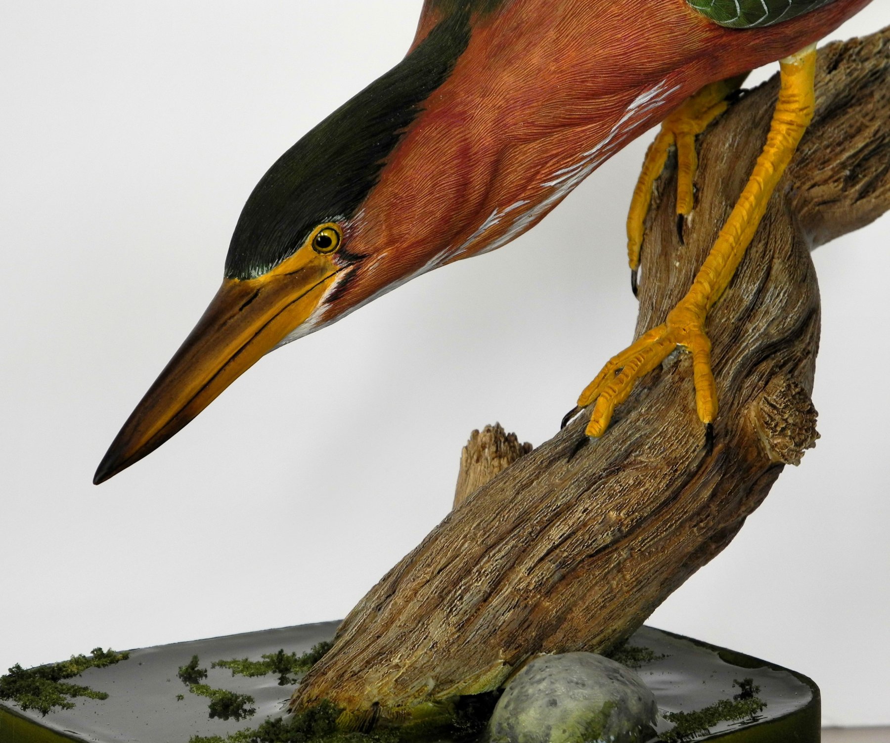
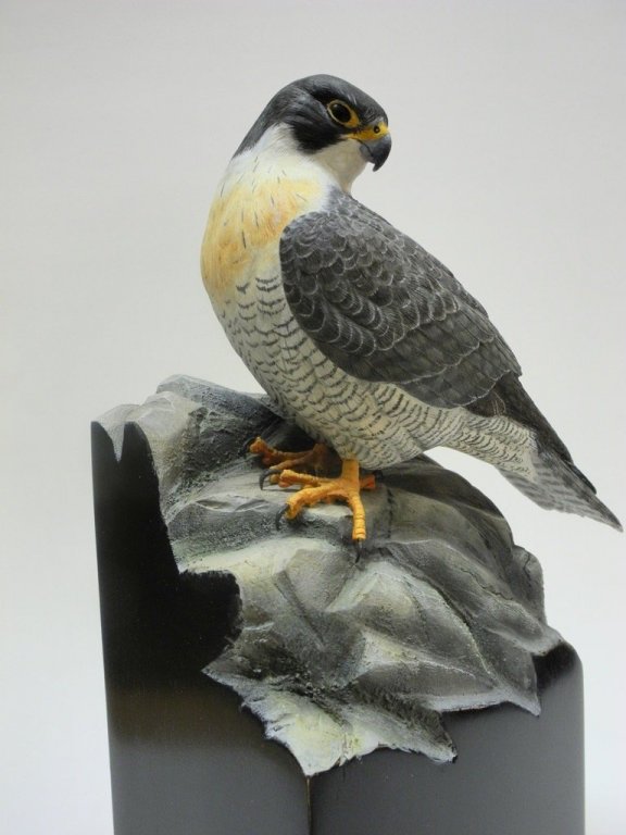
Hi Kurt - each of the birds was carved from a single piece of Tupelo. The only time I would carve separate pieces would be for open wings or possibly a spread tail. Naturally, the habitat is made from separate pieces.
-
Thanks Gary. When I’ve decided on the bird to carve, then I find an action photo of the bird in a natural setting and try to capture that action - makes for a more realistic and Interesting piece. Thanks!
-
Hi Kurt. The plans I have are for 1:24, but I’m going to work at 1:32 so the comparison to Kathryn will be more accurate when they’re shown side by side.
-
Thanks Carl. I’ve enjoyed the bird carving, but now I find that I like the challenge of model ships even more. Thanks Druxey!
-
Thanks Kurt. Takes a lot of patience and a steady hand. My next project will be the Chesapeake Oyster Sloop J T Leonard. This type of boat was a forerunner of the Skipjack. It will be a plank on frame with some planks left off to show the interior work.
-
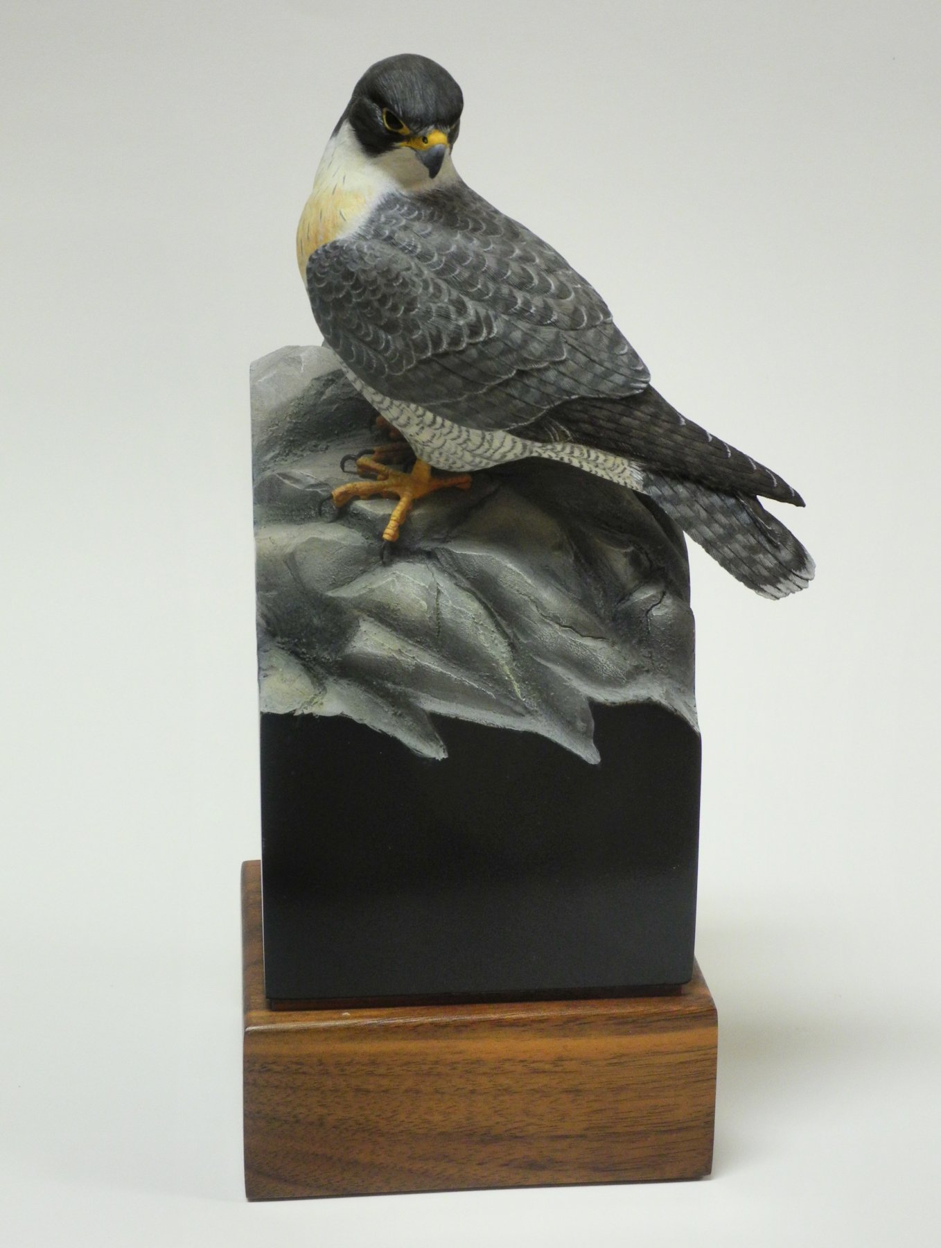
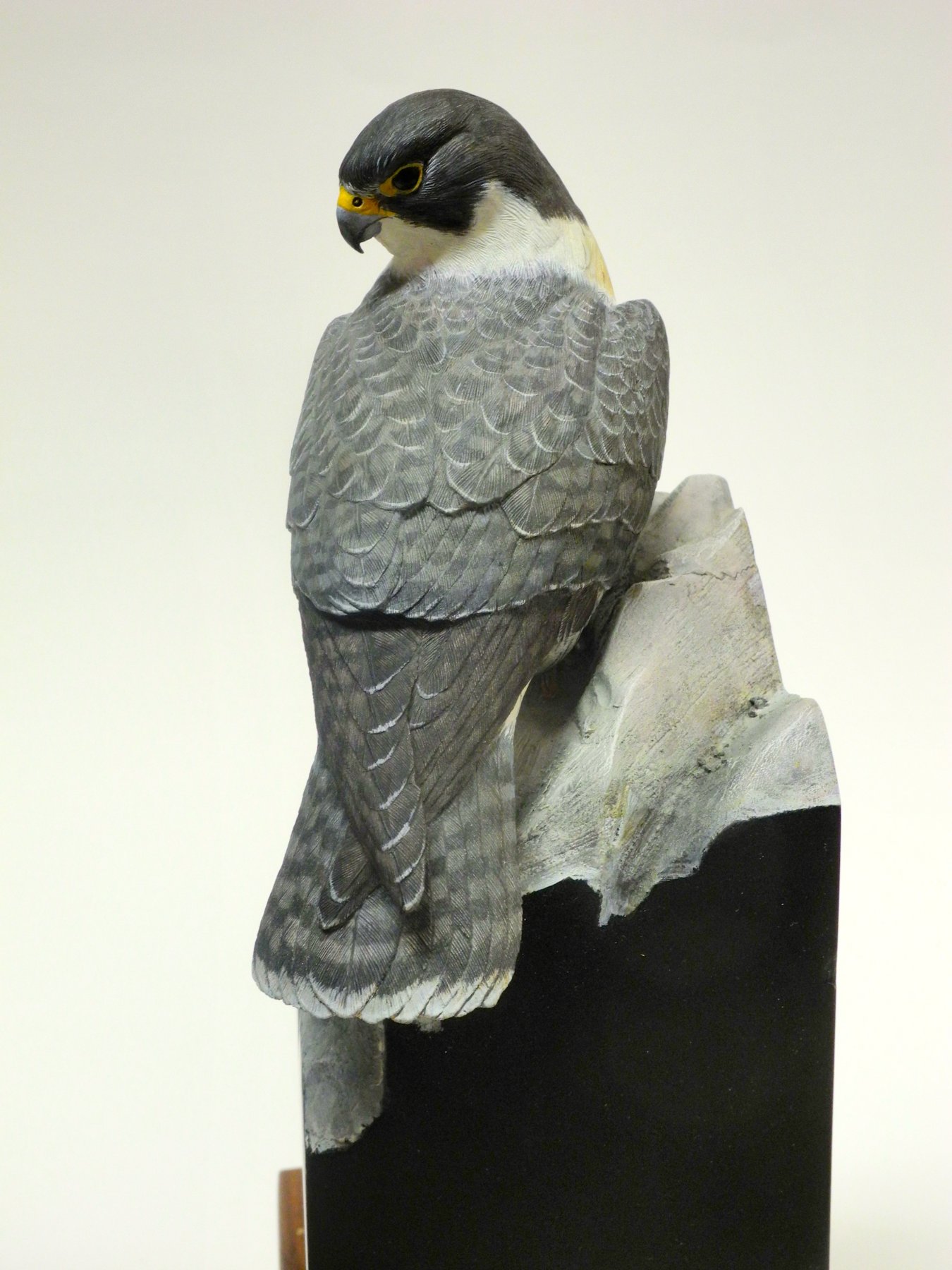
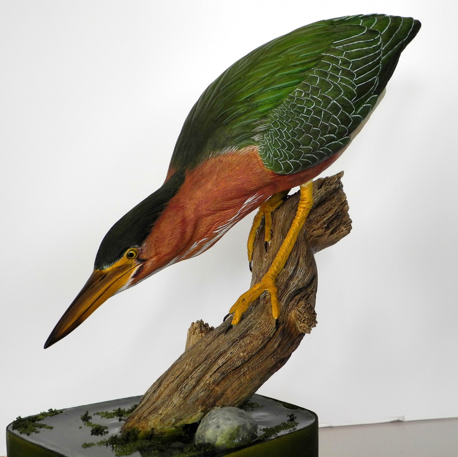
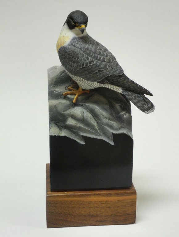
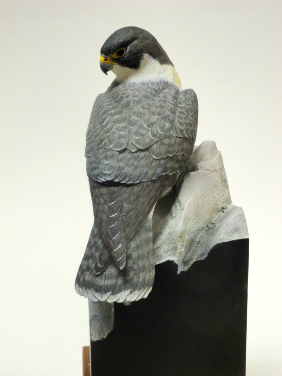
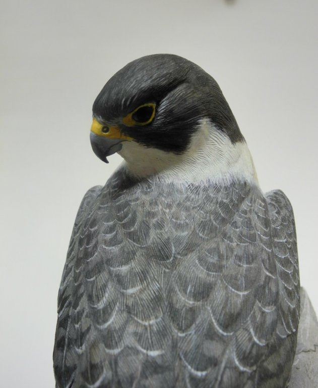
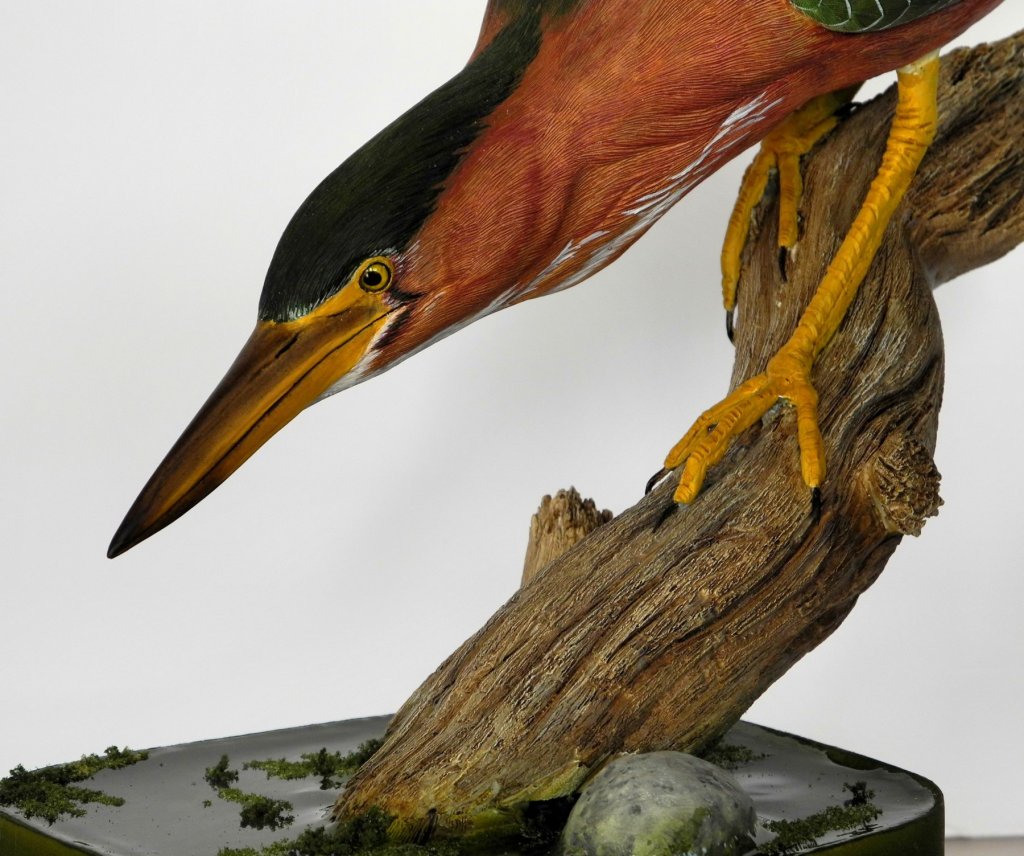
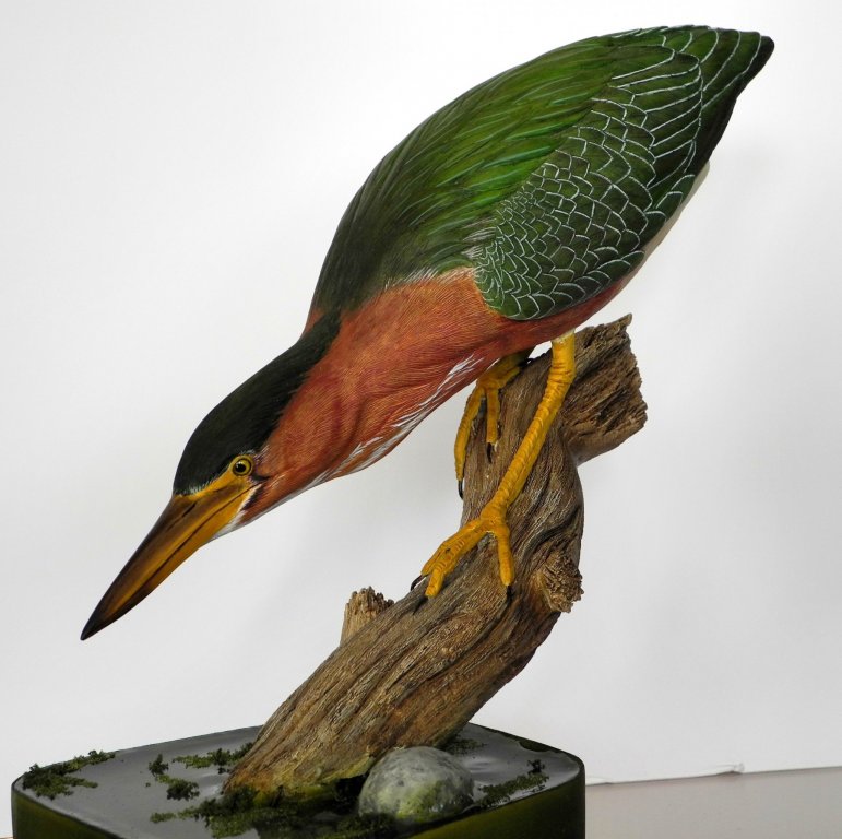
Hi Kurt - a while back (several years) I posted a couple of photos in a topic about other hobbies, but the post seems to be gone. Here are a few photos of my latest carvings: a miniature Peregrine Falcon and a Green Heron.

- 878 replies
-
- 21
-
-
Thanks Popeye. You're absolutely right - I think most of my time has been spent trying to find the right way to do something, and then it gets done pretty quickly.
-
Hi Kurt. I've actually been on Kathryn twice while she was docked, so I was able to take a lot of photos. I also have a couple of friends in the area, having met them at the Ward World bird carving show several years ago. Both of them are modelers and are very knowledgeable about Chesapeake work boats (one of them actually crewed on a skipjack when he was younger) and have been a great help in understanding some of the details. Thanks Hoss!