Mahuna
-
Posts
1,504 -
Joined
-
Last visited
Content Type
Profiles
Forums
Gallery
Events
Everything posted by Mahuna
-
 Hi Patrick. I'm running out of superlatives - all I can say is WOW! For a 'work in progress' the paint looks really good.
 -
Hi John - thanks for the suggestion. Unfortunately 3.1mm scales to 4 inches on the model. The rings and connectors are only about 2.5 inches. I'm satisfied with the approach I've taken - just need to make some changes to get a little more precision and consistency.
-
Thanks for the suggestions Carl - I'll give them a try. Hi Patrick - I'll keep on trying. Hi Druxey. I'll try that - I'll need really small pins (probably very small piano wire). Ron. Yes, they are twisted rings, but I'm using the thread to simulate that. It's a stock photo site, so I'd rather not post it online. If you're referring to the photo of the real dredge you're correct. They're not really part of the net - they're holding the ring net and the rope net to the frame.
-
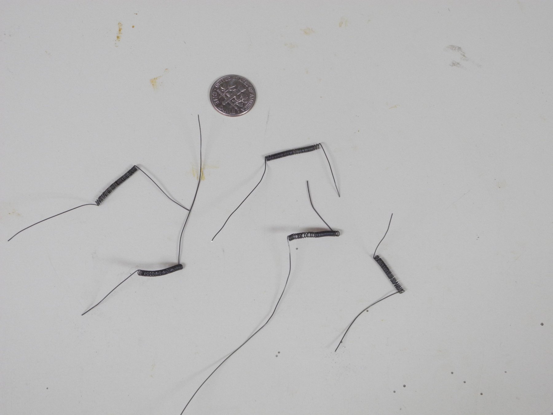
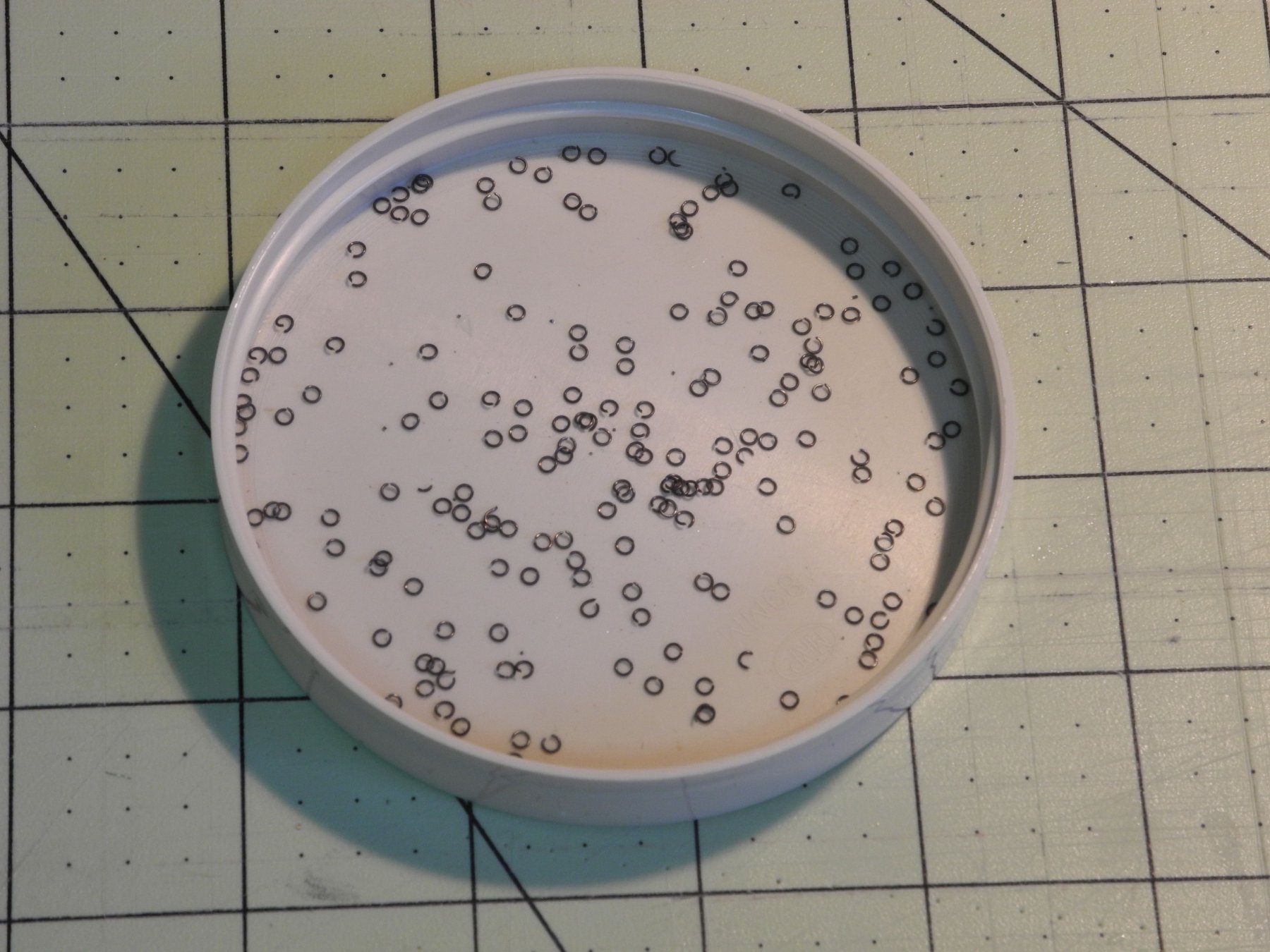
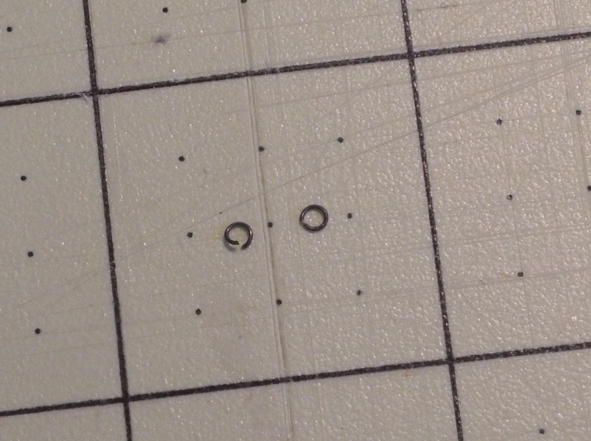
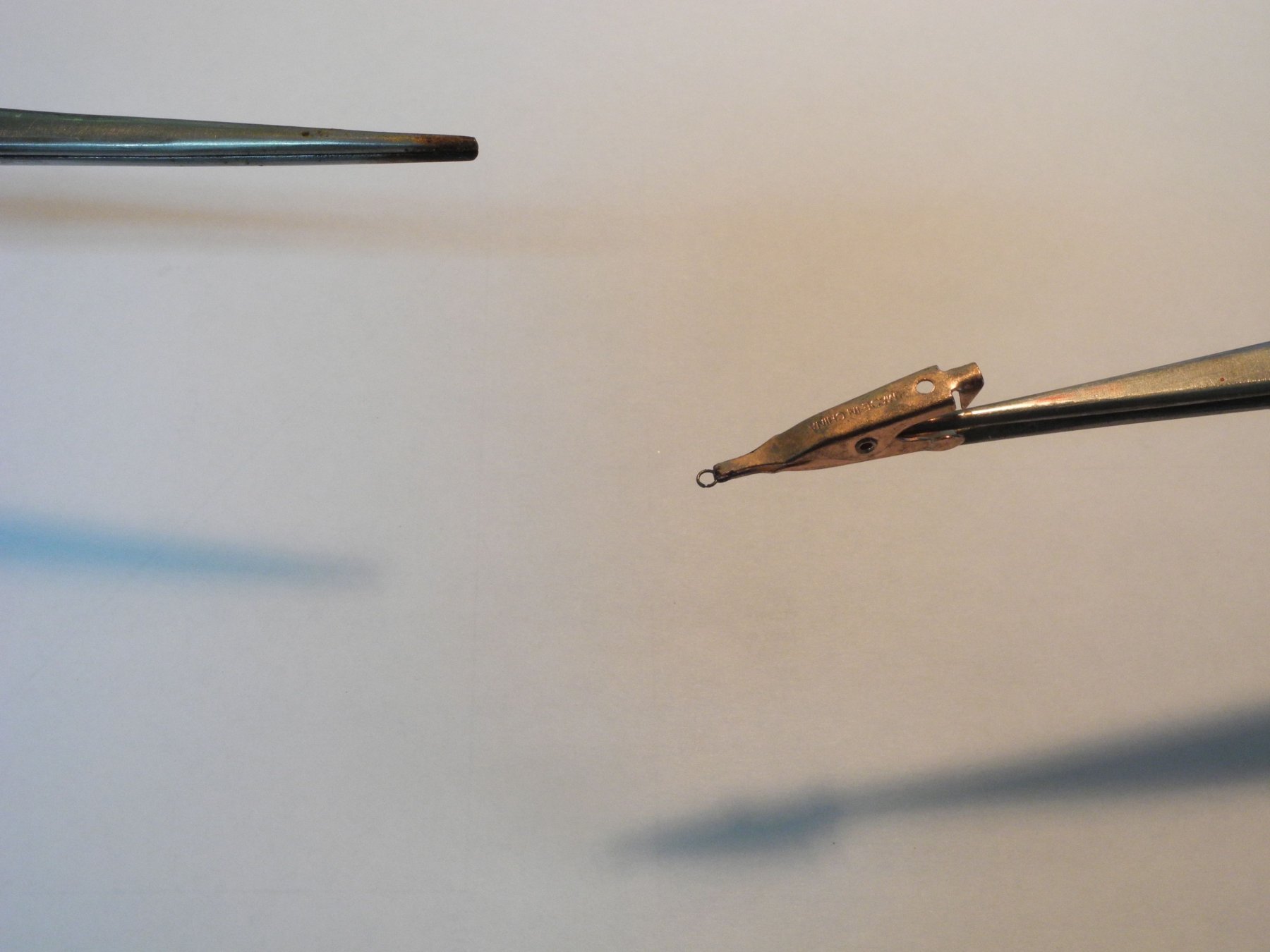
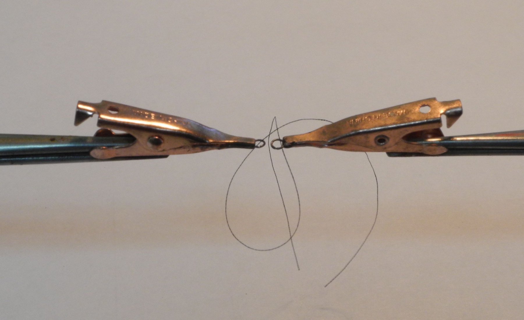
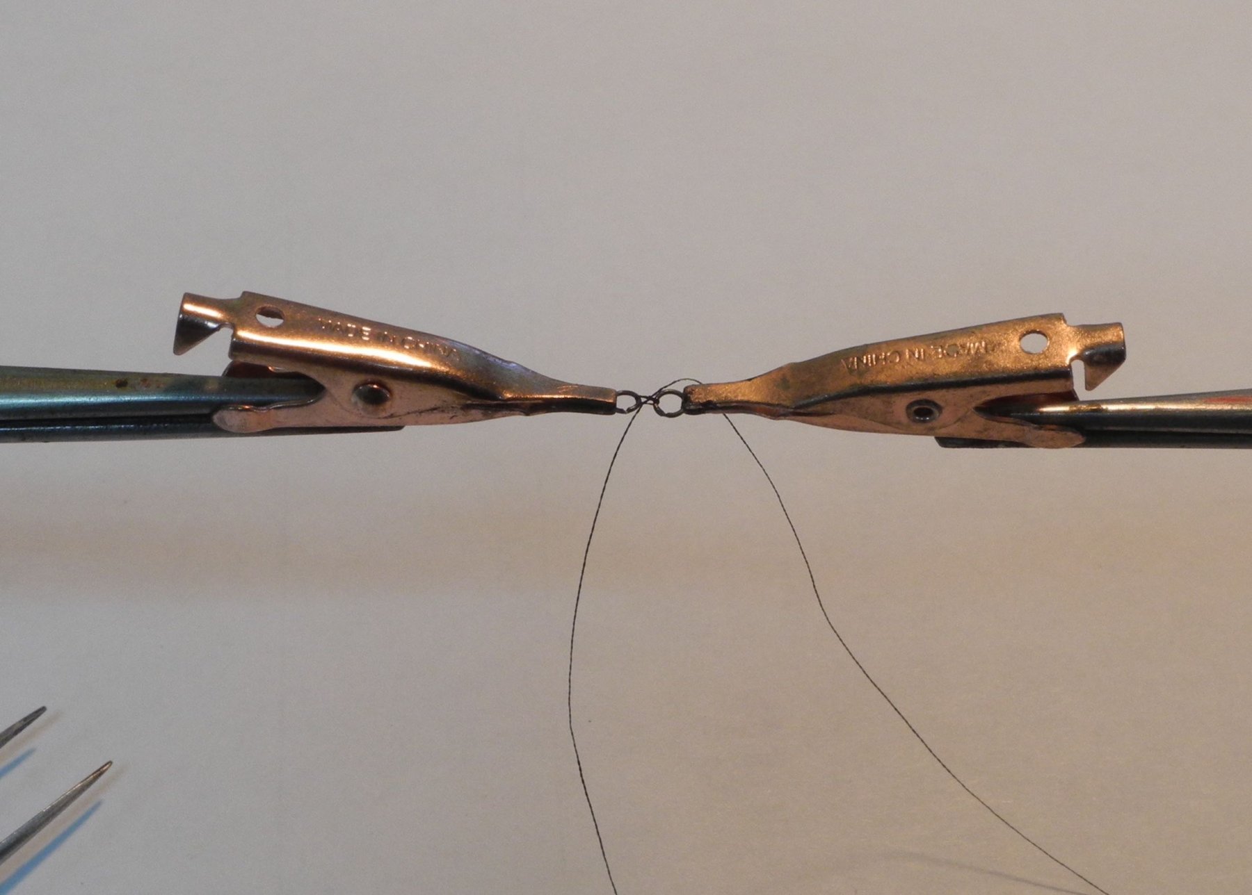
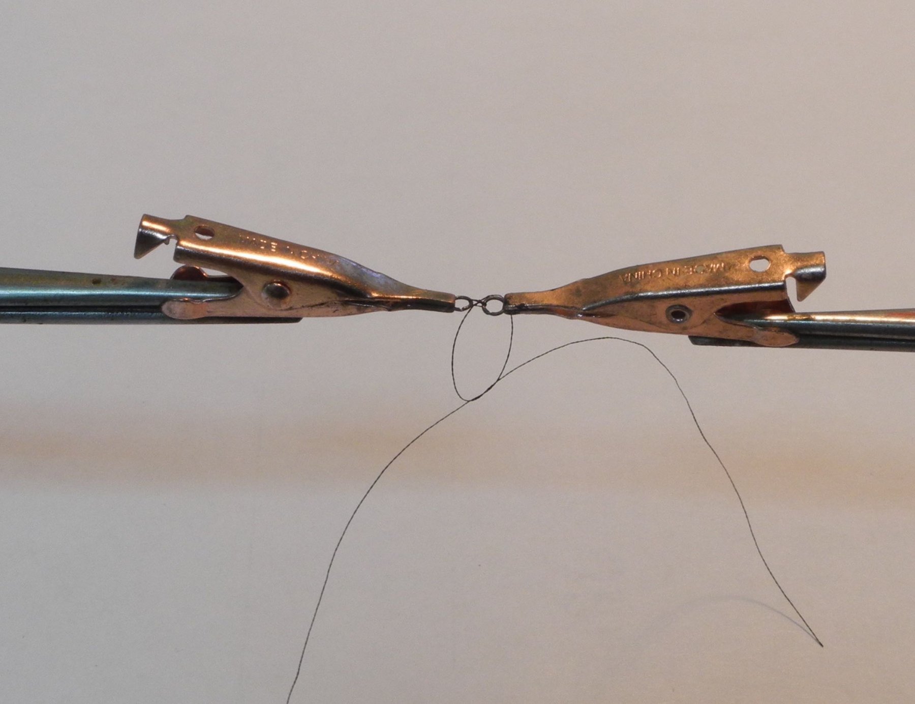
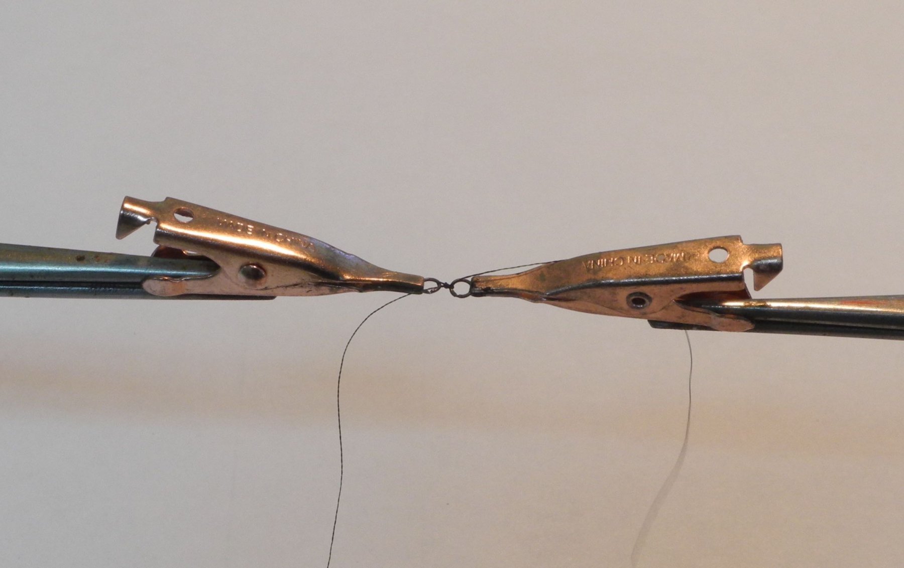
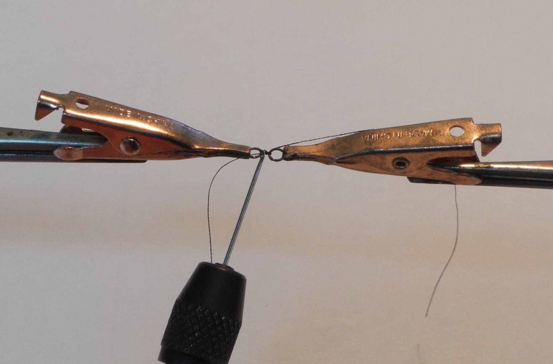
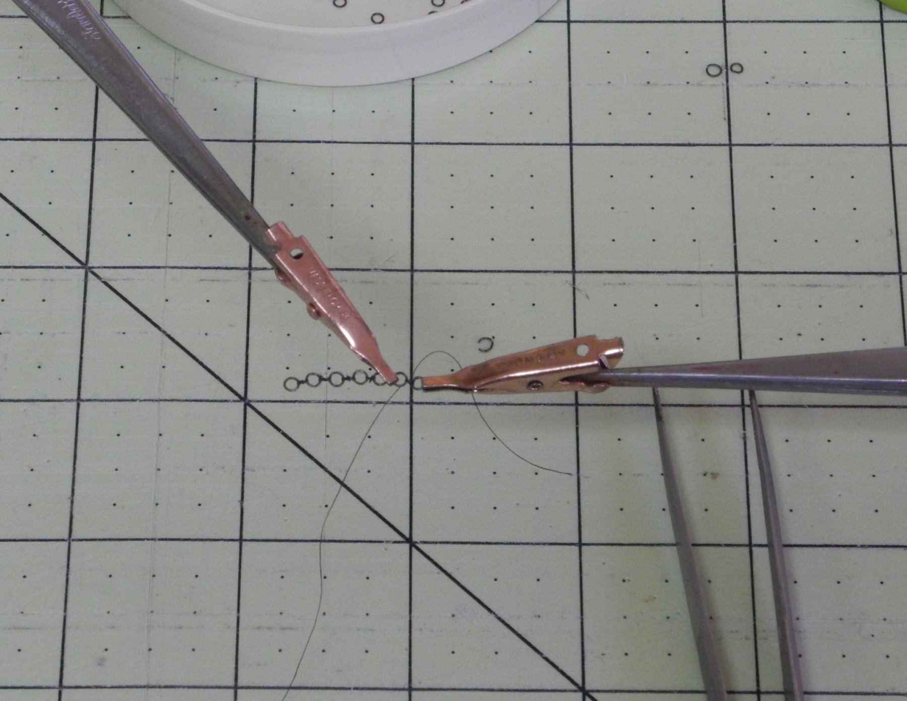
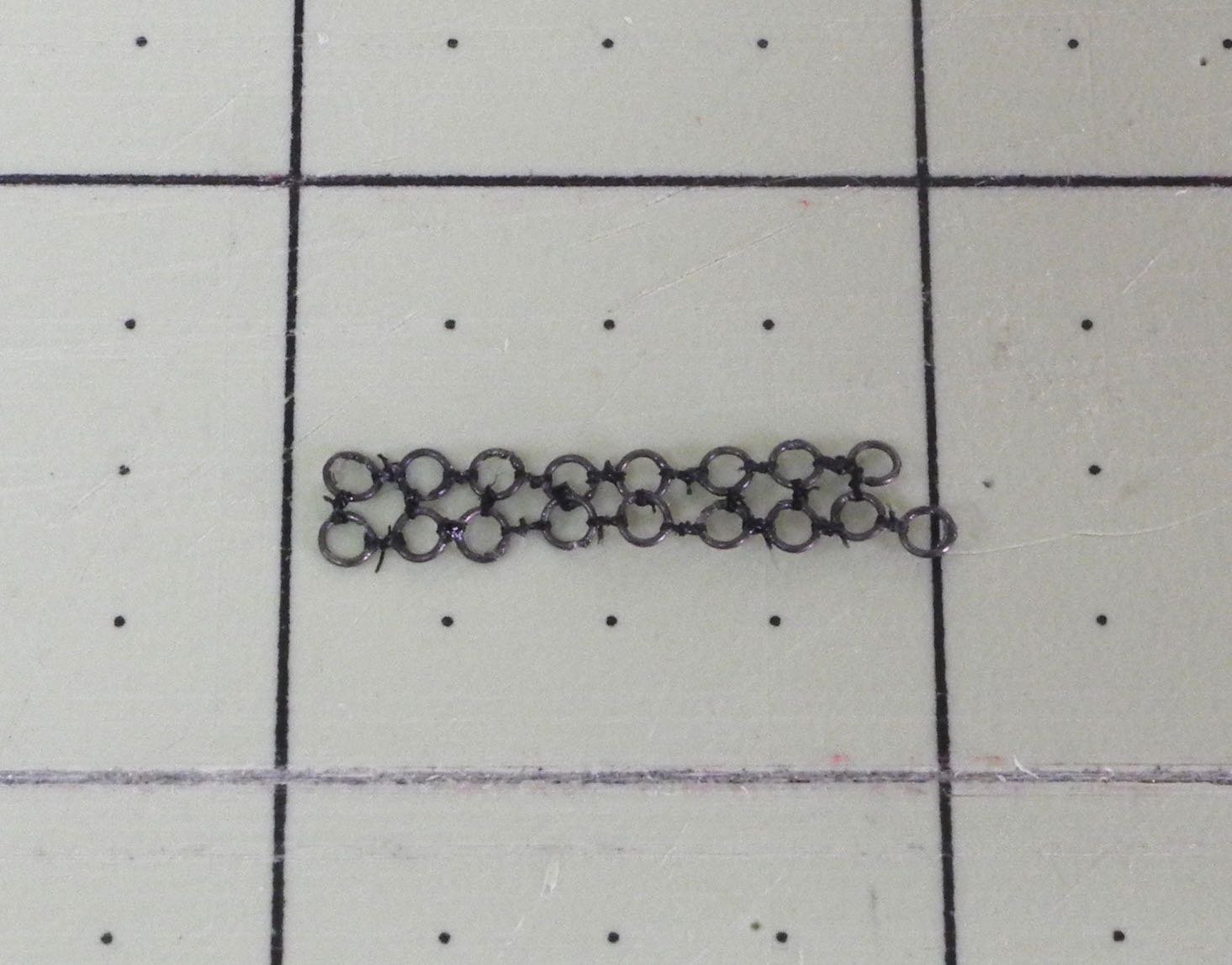
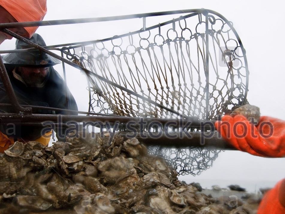
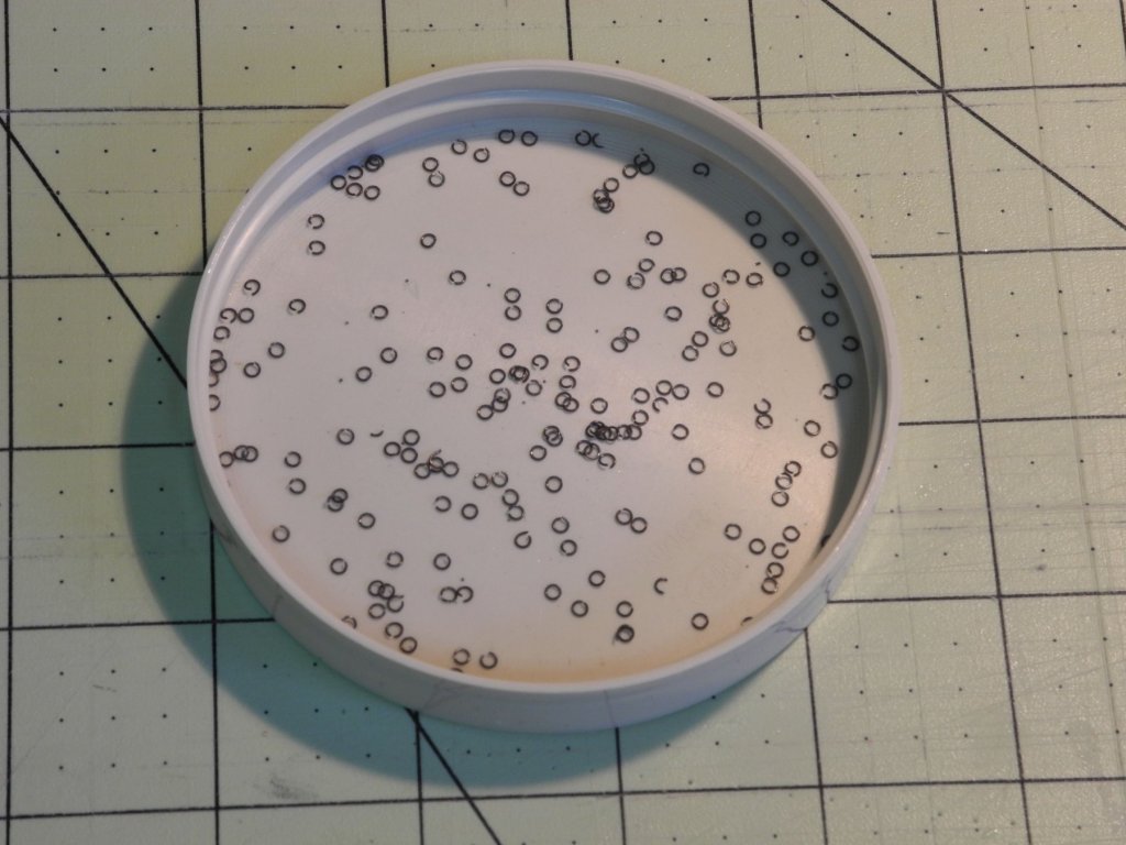
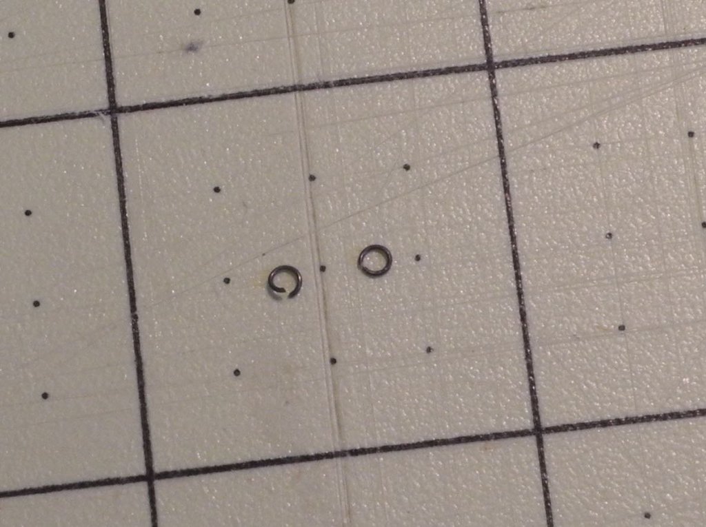
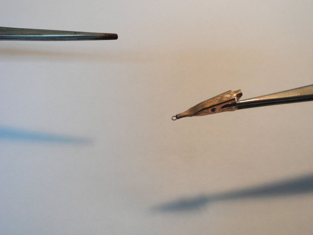
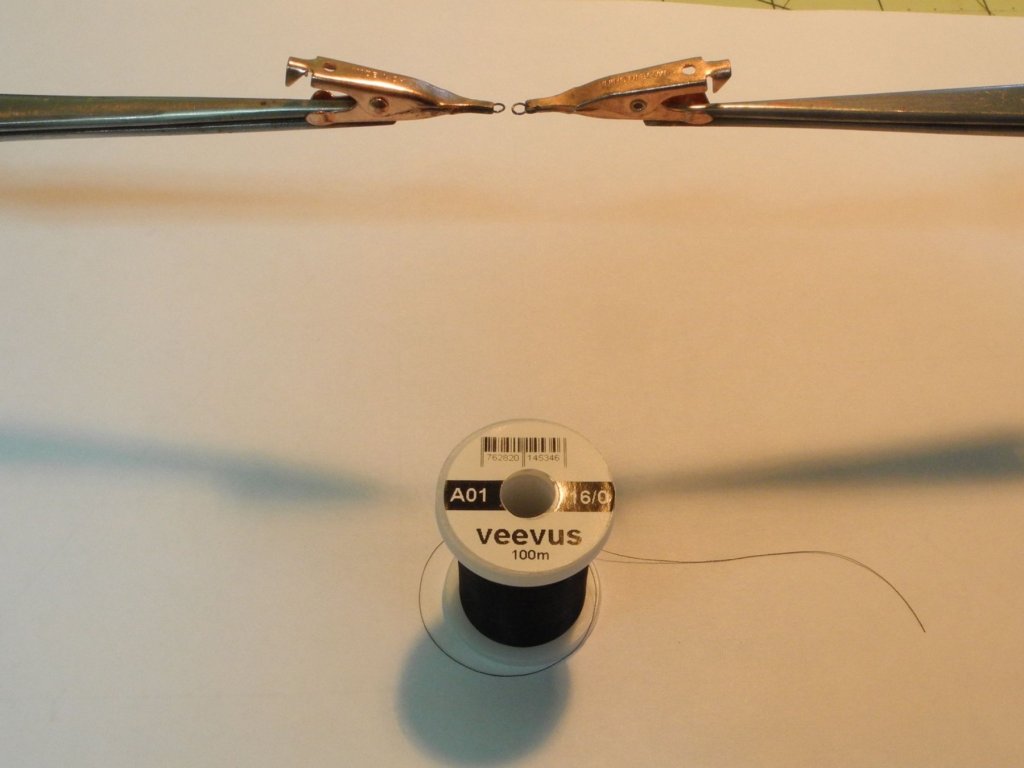
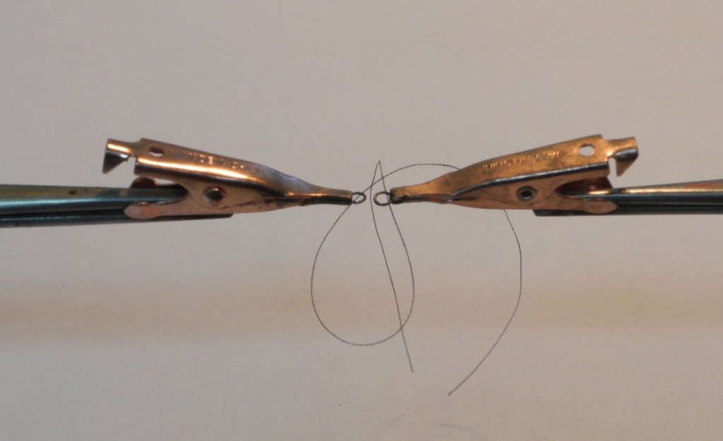
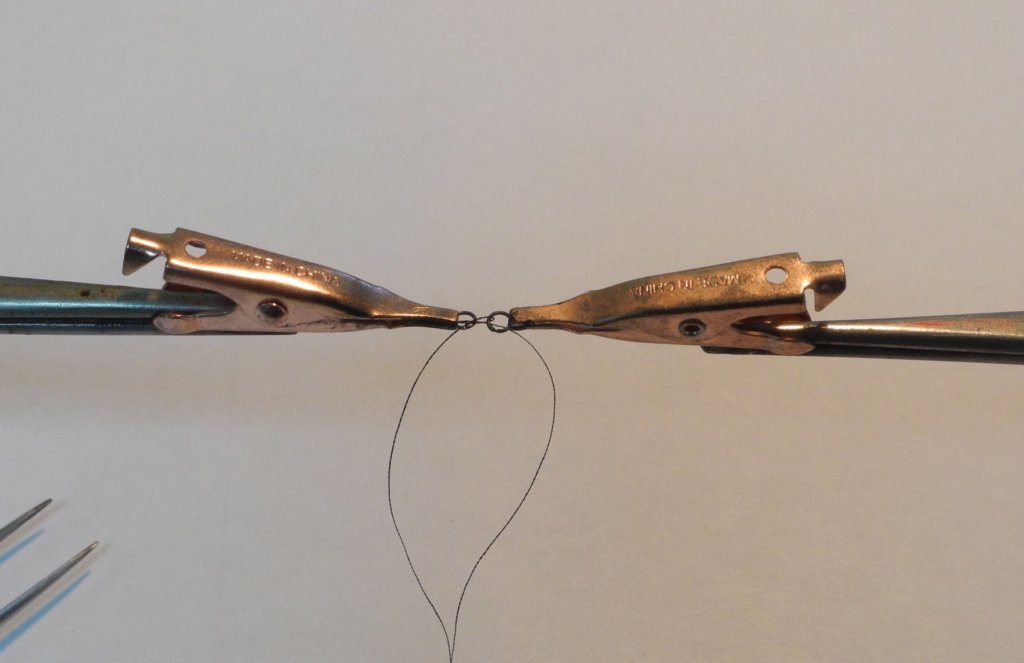
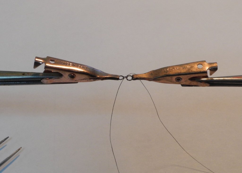
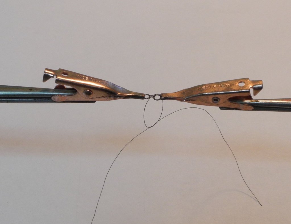
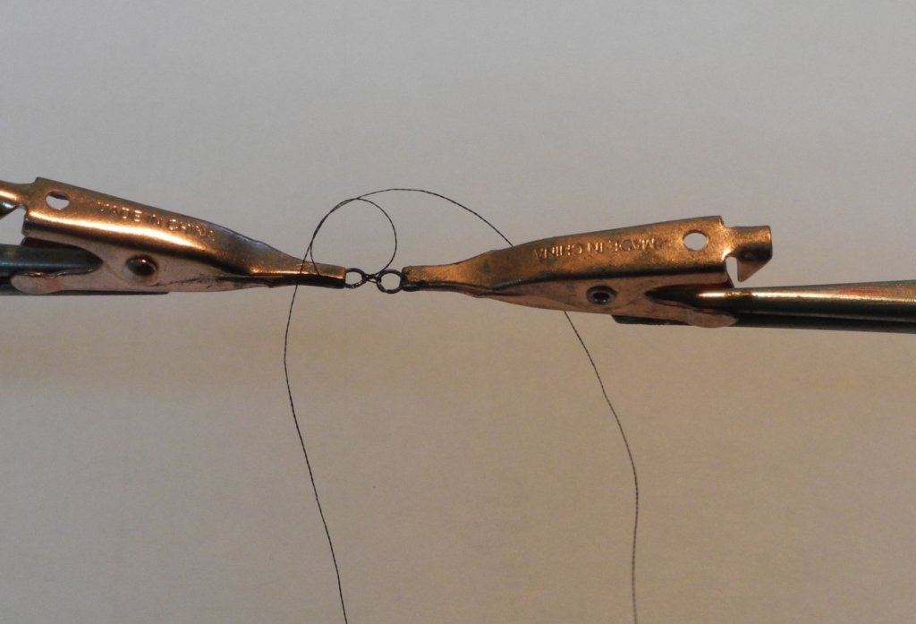
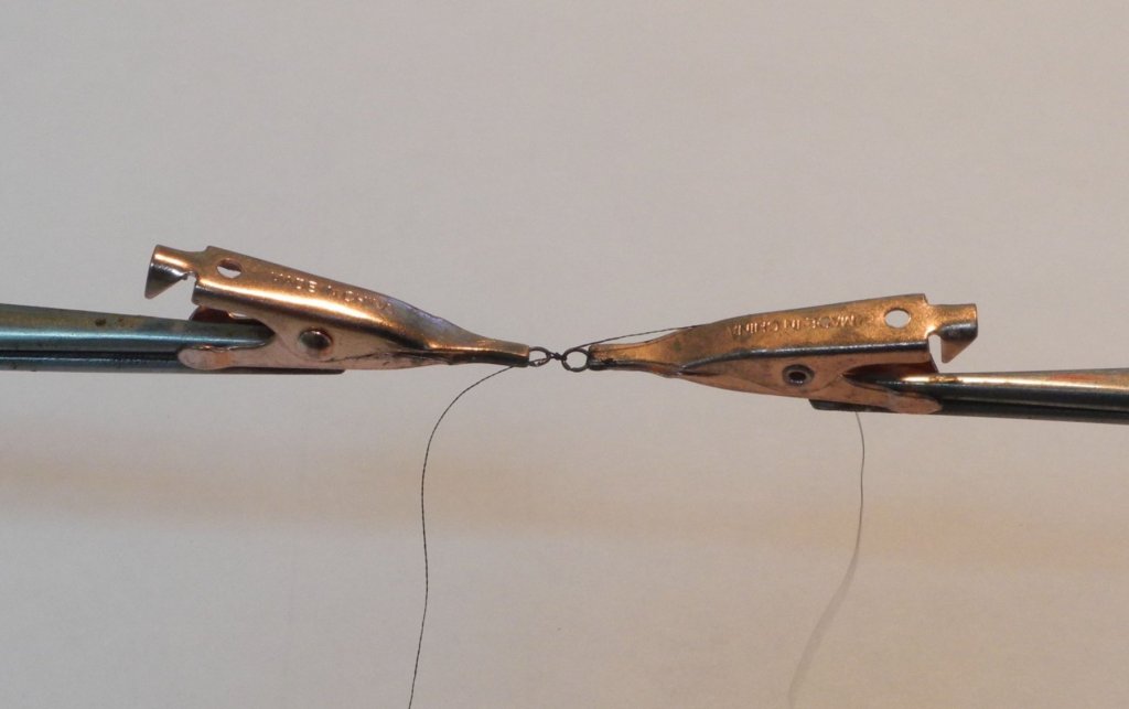
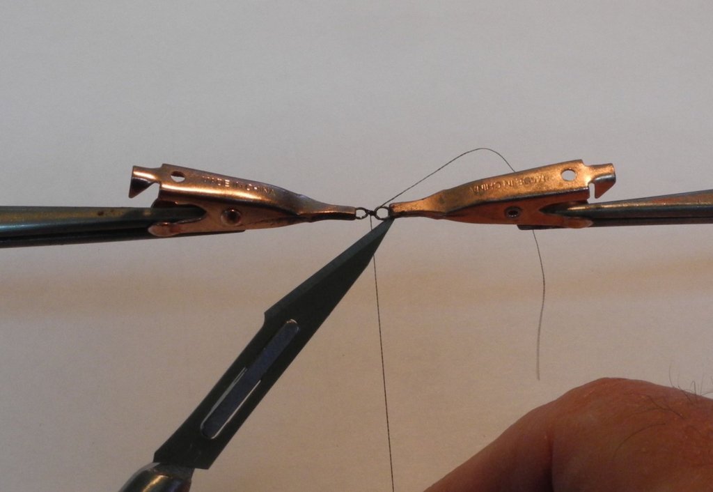
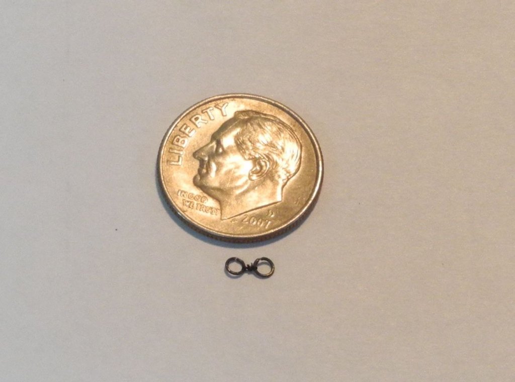
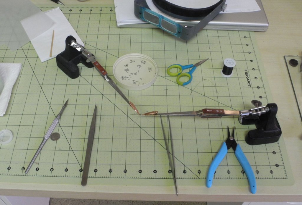
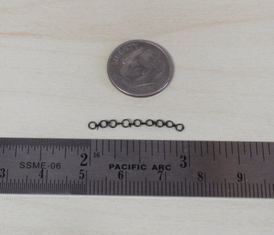
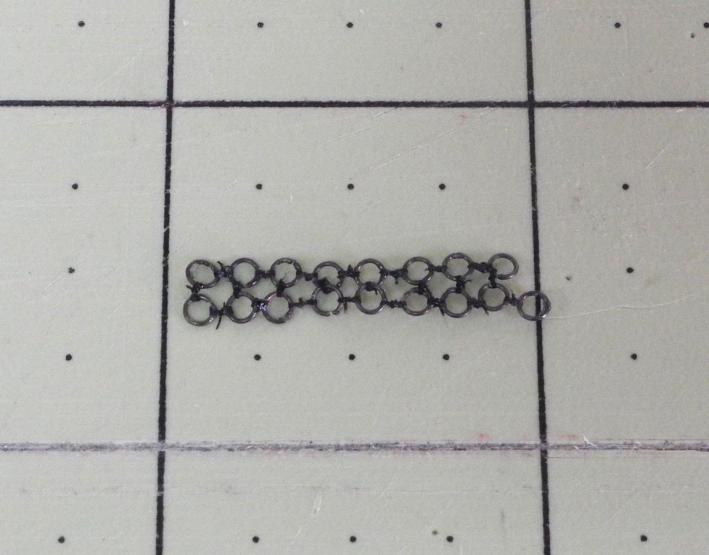
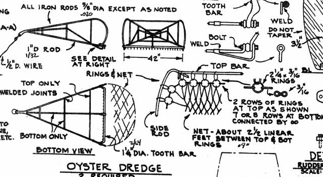
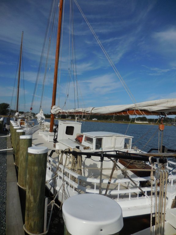
Part 96 –Oyster Dredge Kathryn’s dredges are very similar to the dredges found on all skipjacks. They consist of a dredge body of welded steel rods, with a basket consisting of linked rings for the bottom part of the basket, and a rope net for the upper part of the basket. The basket is attached to the body via rings. The following photo is one of the better dredge photos I was able to find online. The plans for the Willie Bennett have a very good pictorial description, including measurements, for the dredges. My intent is to make the dredges as close to reality as possible. My first task was to determine how to make the network of rings for the basket. The rings were made by wrapping 34 gauge black wire around a #53 drill bit – this gave coils of rings that are the correct scale dimensions. The individual rings were cut off the coils The rings needed to be pressed closed and straightened. This was accomplished using a pair of Xuron needle-nose pliers. In the following photo the ring on the left is as cut from the coil, while the one on the right has been straightened. Given the number of rings involved (plus plenty of spares) this was a fairly boring but necessary task When manufacturing the ring groups, the individual small rings were held in the miniature copper alligator clips from Radio Shack. These clips were in turn held by third-hand tweezers held in a weighted base. I decided to use thread as the figure-eight small rings that are used to join the round rings of the net. I tried .007” thread, but this proved to be much too thick. I have some 16/0 fly tying thread (about the diameter of a thick human hair) which proved to be satisfactory. The only problem in using this thread is that it’s so thin that it easily slips through the opening or split left in the rings. To correct this, each ring had a small drop of medium (gap-filling) CA glue applied to the split in the ring. Each end of the thread was fed up through the pair of rings to be joined and then down through the opposite rings. The ends of the threads were brought up each side of the thread weave created above and tied in a simple knot. The ends were brought down around the thread weave, and double knotted. Finally the thread ends were brought up again and a final knot was made on top of the ‘figure eight’ configuration. A drop of CA glue was applied to the knot to secure it, using a small pin held in a pin vise as the applicator. After the CA dried the ends were trimmed using a sharp scalpel. The result was a passable pair of rings joined by a “figure eight”. I proceeded to tie a few rings together, and found that holding a string of rings required an adjustment to the placement of the holding devices. (As can be seen in the above photo, Optivisors were a necessity for this process) Overall, the experiment was a success. I found that I’ll need to use something to keep the intervals between the rings consistent, and I also need to follow a better method of tying and gluing the threads to allow the joints to remain loose and flexible. I’m fairly confident that I’ll be able to make a net of rings for the dredge basket. The net of rope or twine will also take some experimenting, but I have a few ideas of how to get it done. This will have to wait until the dredge frames and the ring nets are completed. So, the next priority is to make the dredge frames. Thanks everyone.


- 878 replies
-
- 16
-

-
Hi John. I'm going to try the rope and rings, since that's what I see in any photos I have.
-
Thanks Tom and Gary. The dredges are proving to be an interesting project by themselves.
-
Thanks Druxey. I'm very pleased with how it came out. Thanks John. I've started working on the dredges and hope to have some progress to show soon. Thanks Patrick. It's great to hear from you again.
-
Welcome back Patrick. I'm constantly amazed by the detail you can get into tiny spaces. Awesome!
-
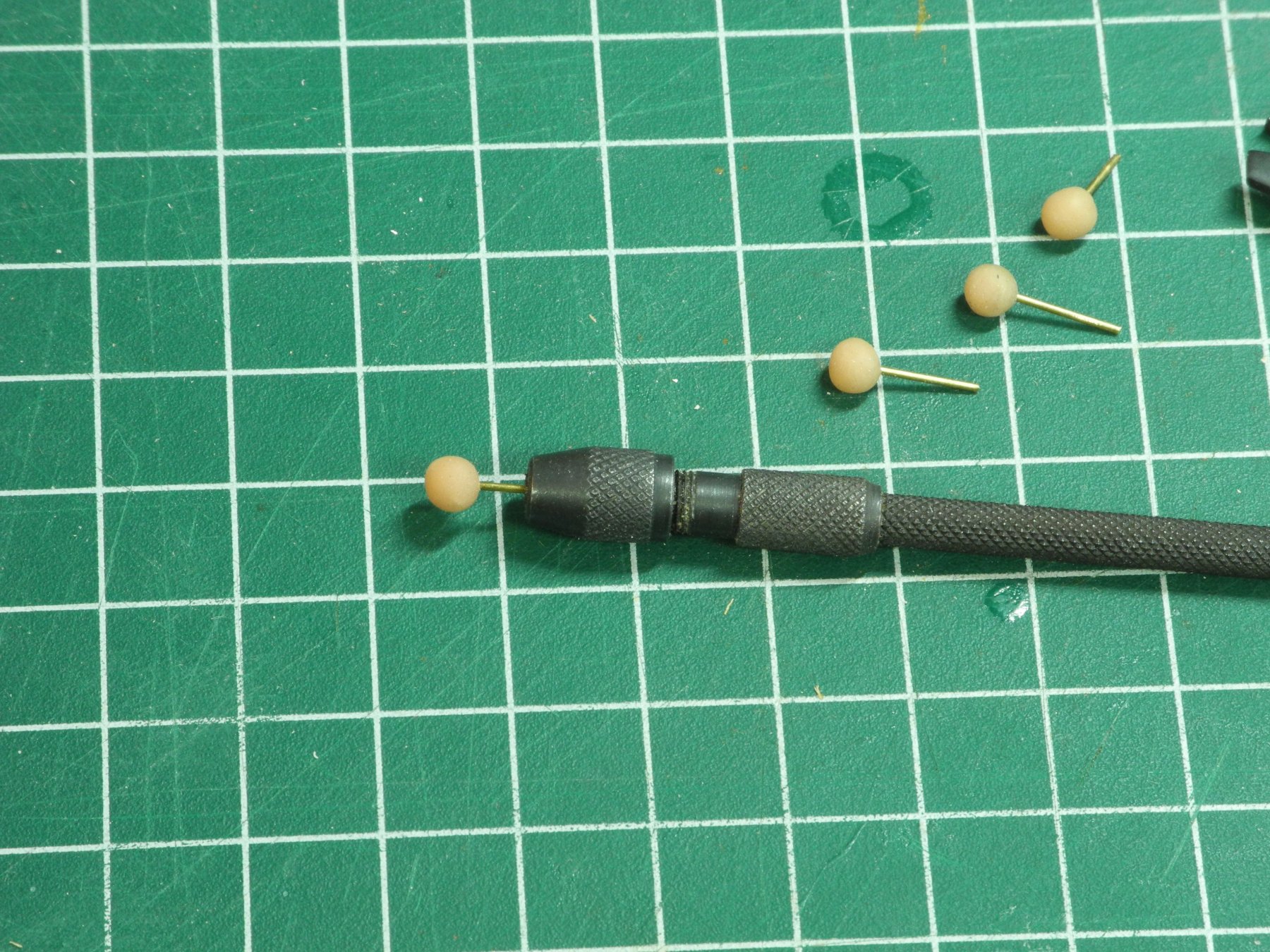
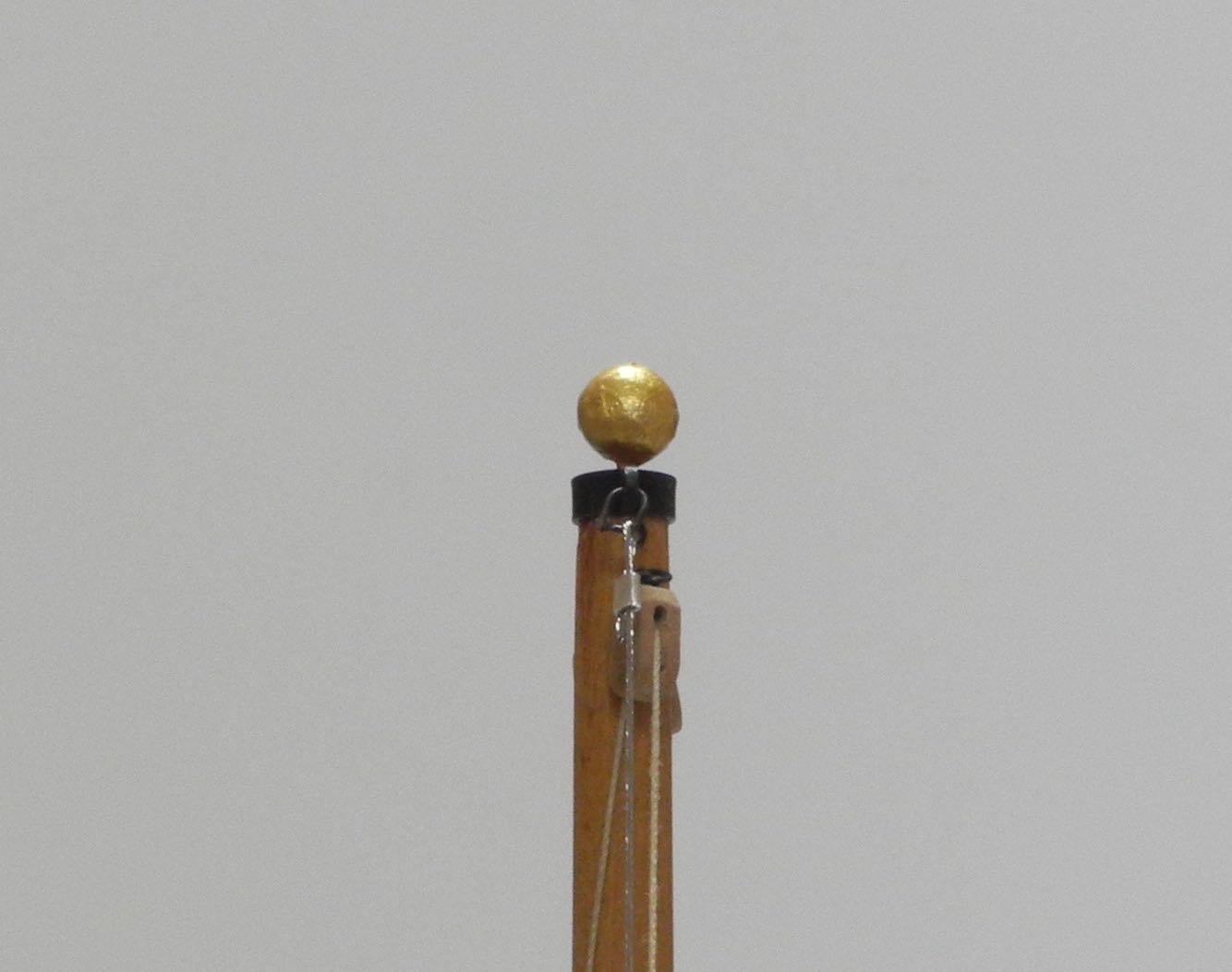
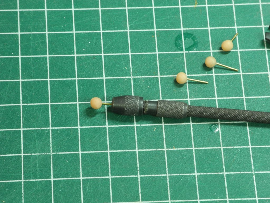
Thanks Carl. Would have been a little easier, but I didn't have any pins with the right sized ball head. Making the balls out of Sculpy took less than 30 minutes. Thanks Rich .... but I told you a million times not to exaggerate!
-
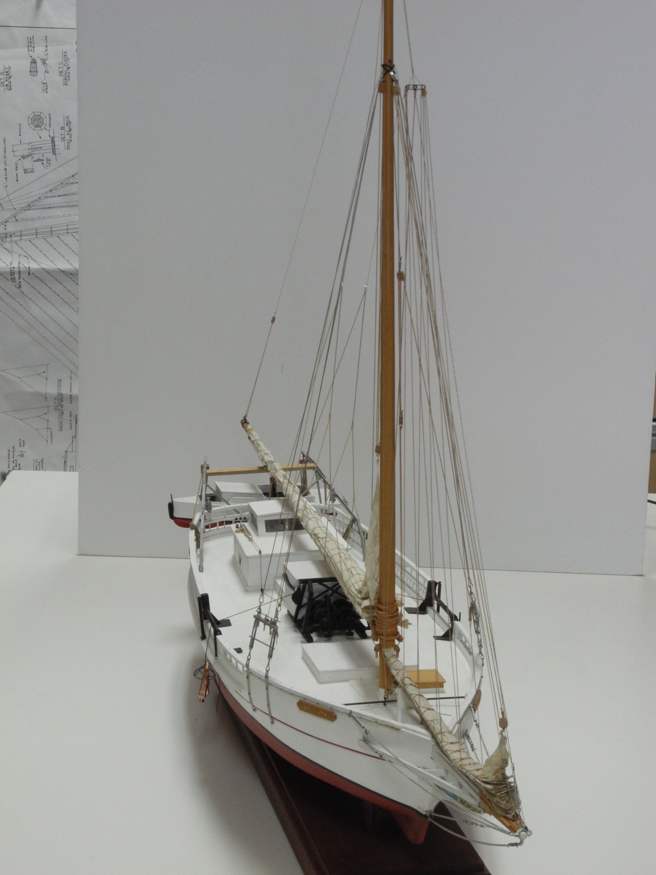
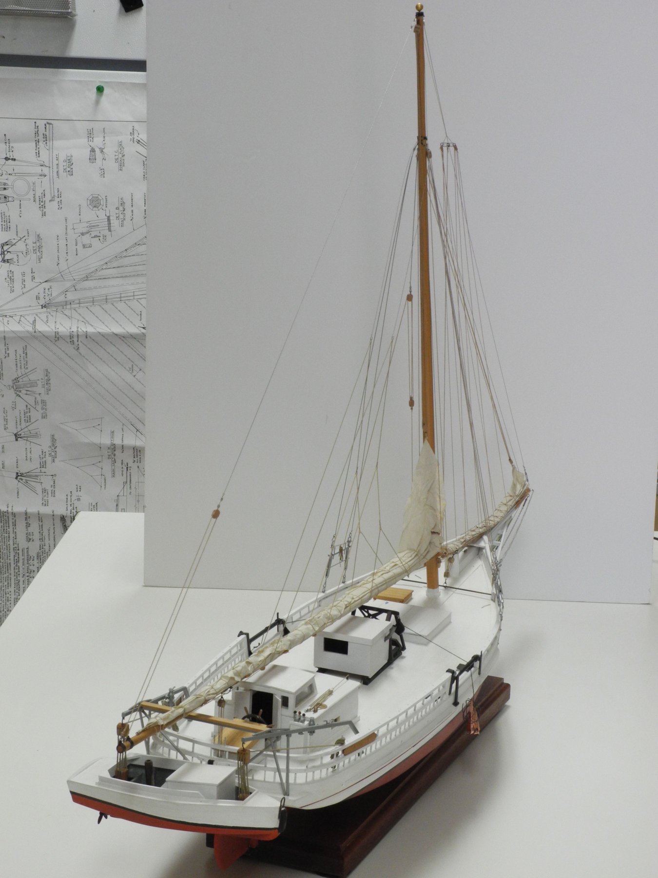
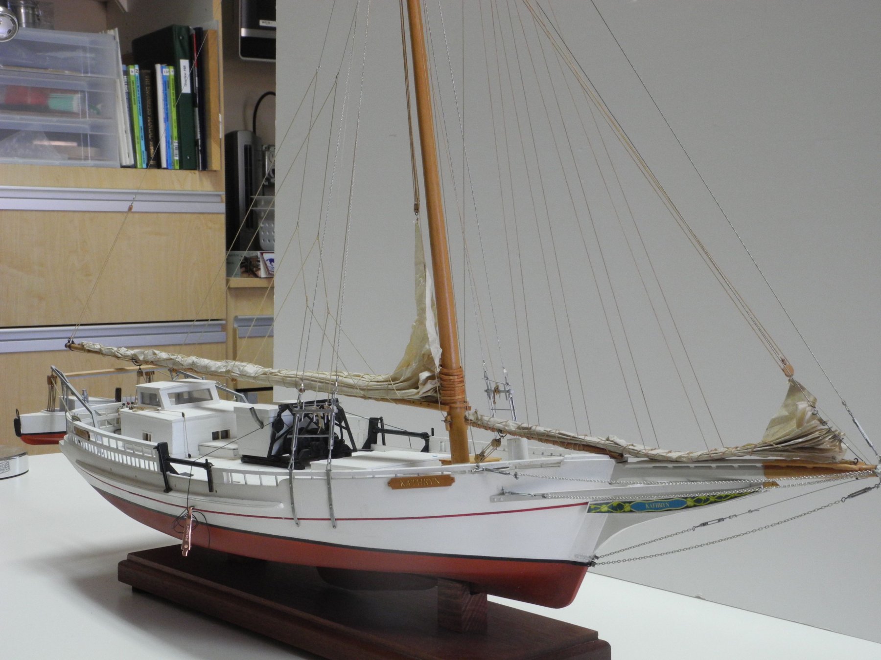
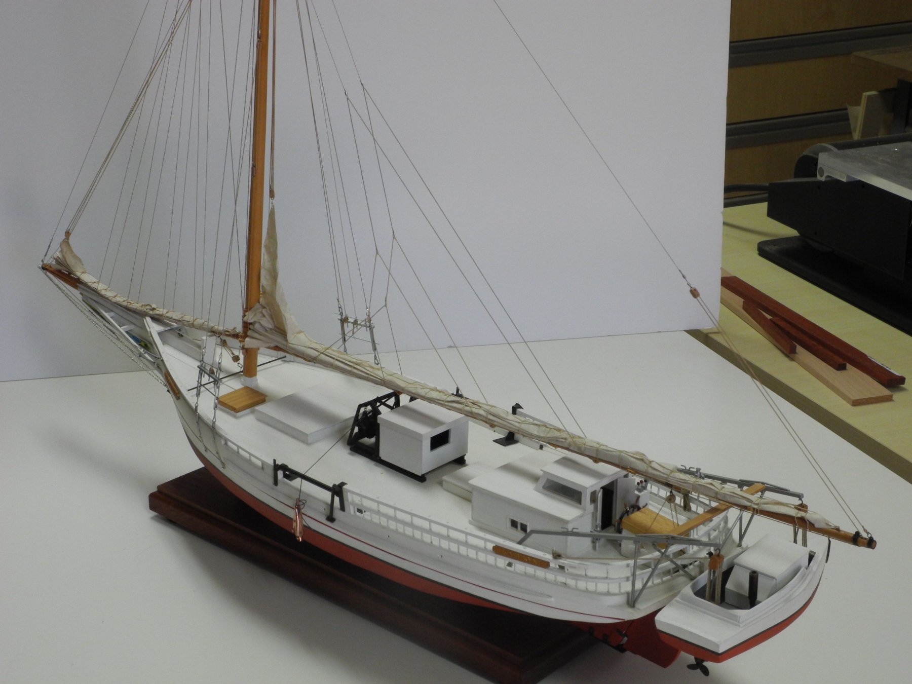
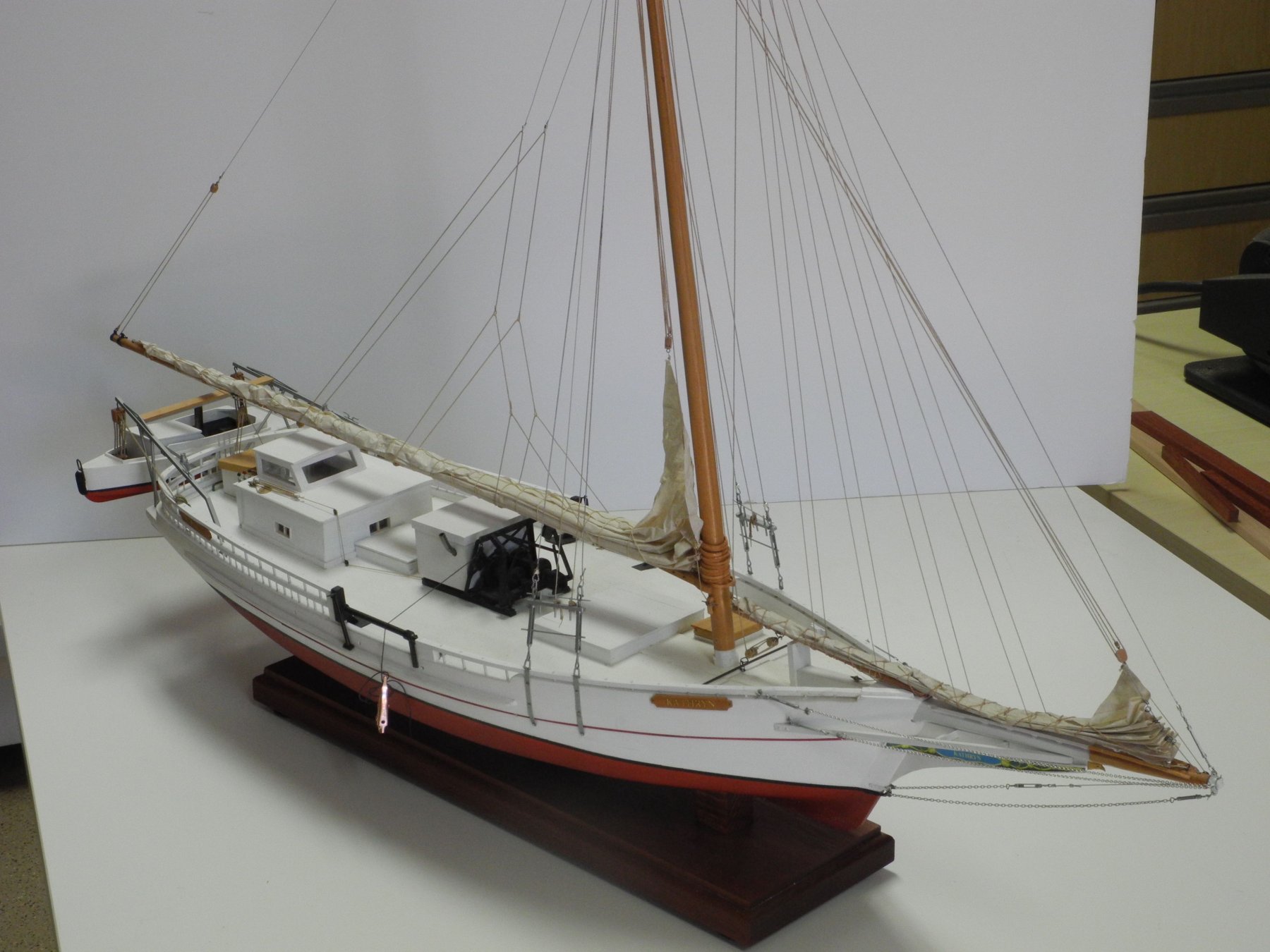
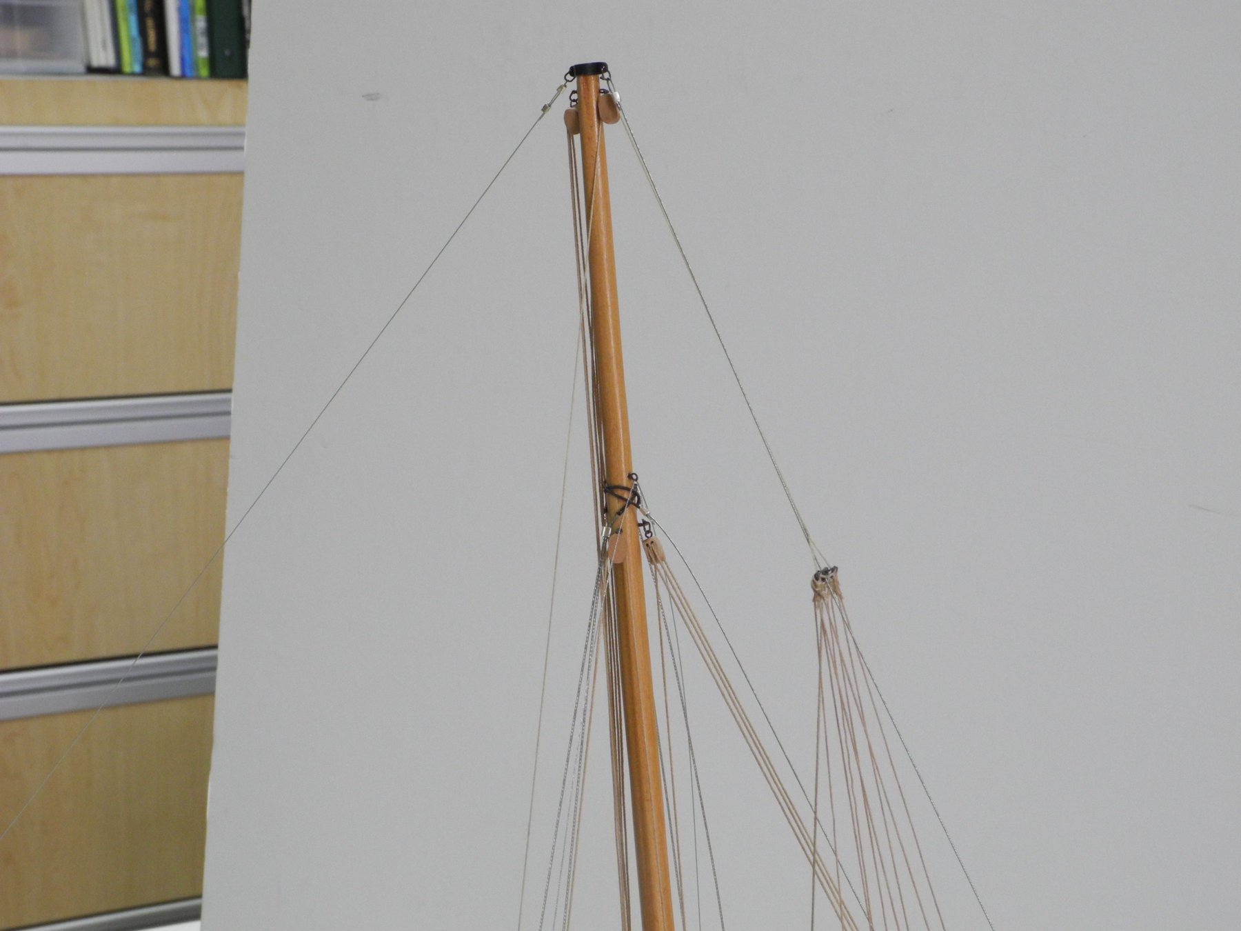
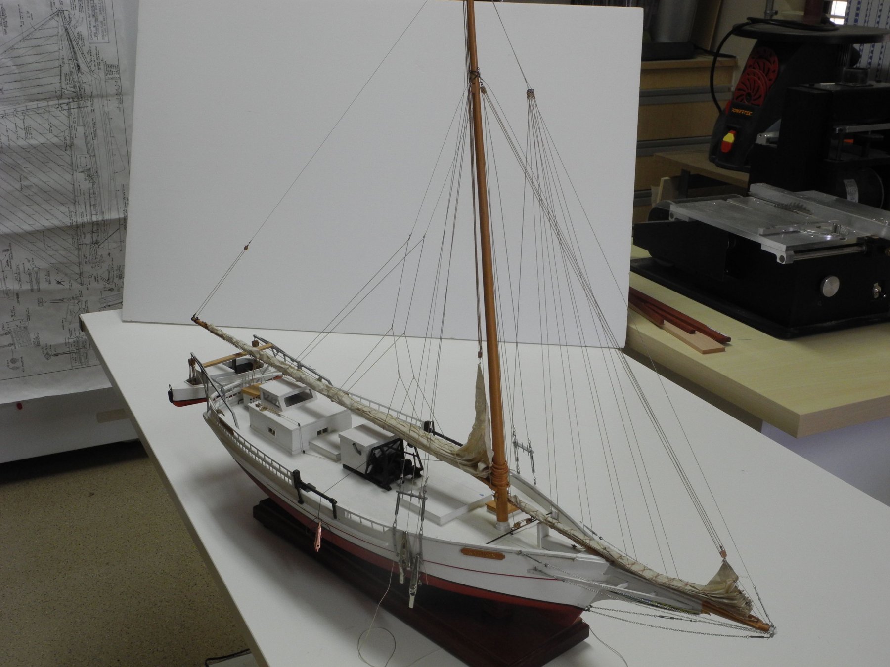
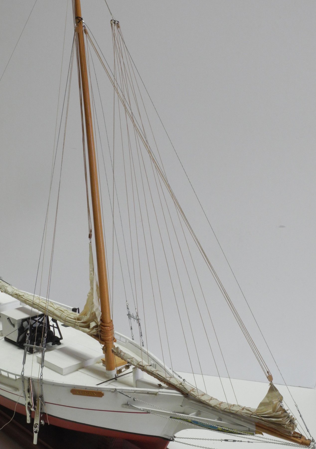
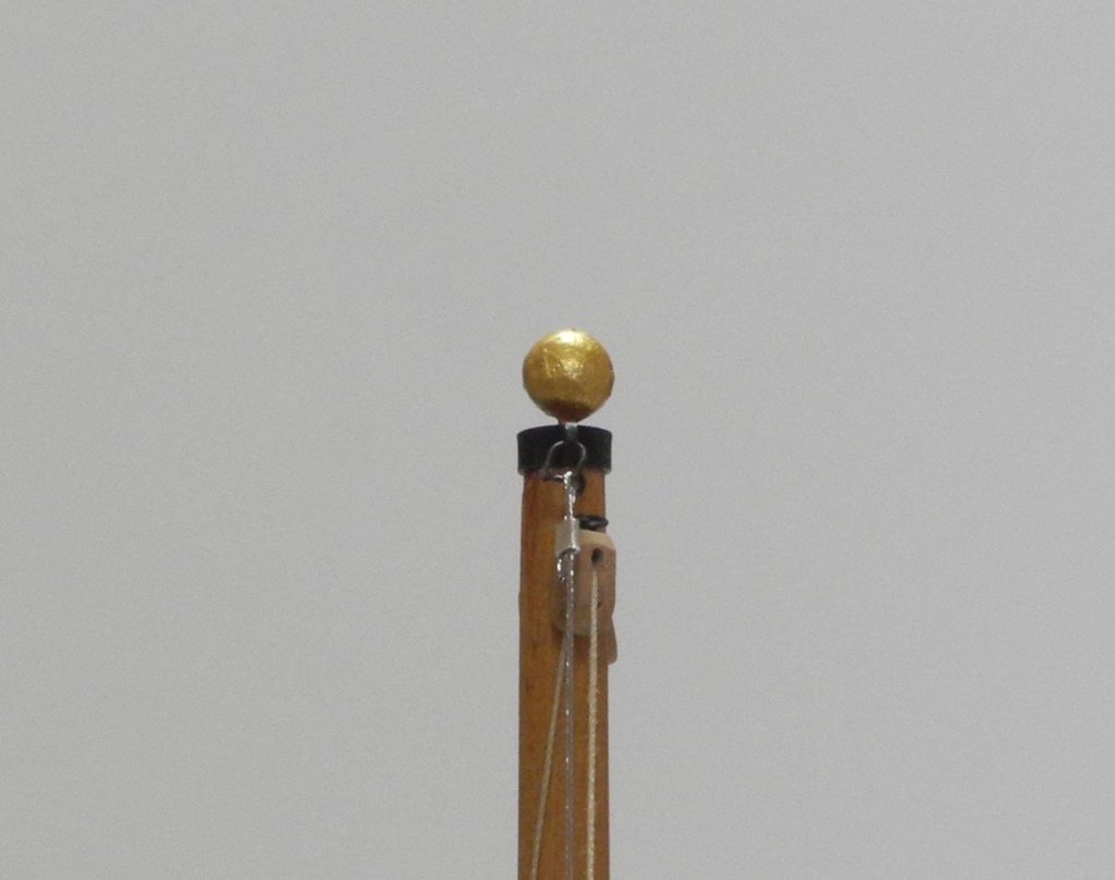
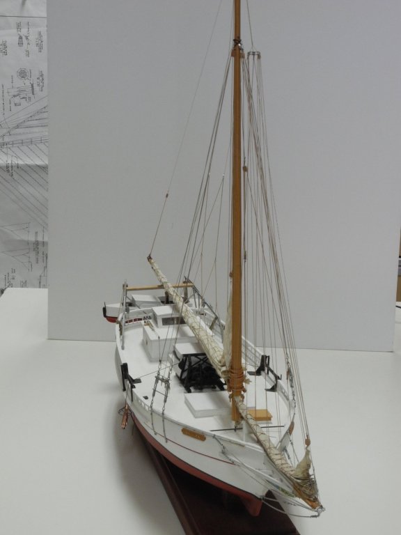
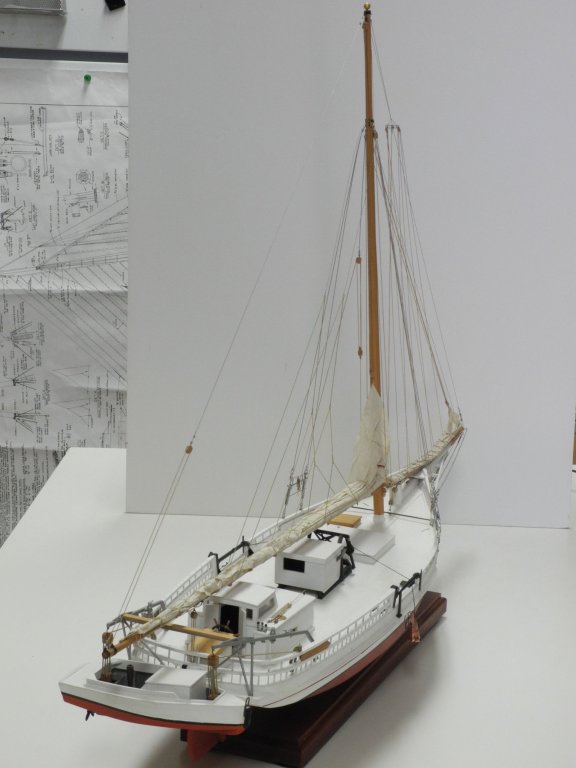
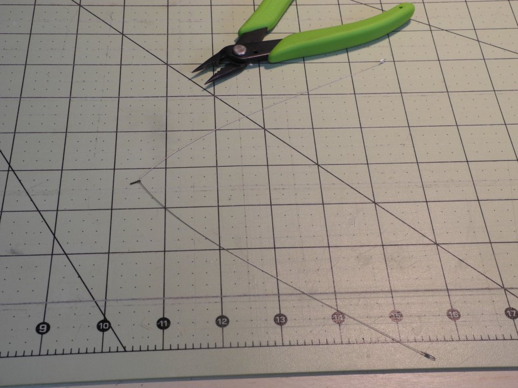
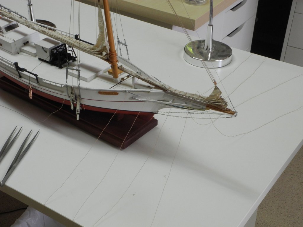
Part 95 –Misc Small Items Just a short post describing some of the last minor details that were added to the model: First, Skipjacks that are fully owned – no debt on the boat – wear a gold ball at the top of their mast. I tried a few alternatives for making the ball: small beads, but these were not fully round; small wooden beads, but I couldn’t find any small enough. I finally settled for making a small round ball using Sculpy. I rolled several balls and baked them. After they were hard and had cooled off, I drilled them to take a 1/32” rod. I chose the one that looked most round to the naked eye, painted it gold, and mounted it in a hole that had been pre-drilled in the mast top. The photos of Kathryn show some iron or steel rods inserted in the body of the shroud’s turnbuckles, and through the clevises at the top of those turnbuckles. These rods serve two purposes: they keep the turnbuckles from loosening, and they provide the necessary leverage when adjusting the turnbuckles. Finally, I made some loose coils of rope to hang off the pinrails where the various lines were secured. So Kathryn is now finished, but I still need to make the dredges. Here are a few photos of the model. I’ll need to take some “studio” shots once I’m finished with the dredges.


- 878 replies
-
- 23
-
-
Absolutely beautiful Ed. You've set a very high bar us.
- 3,618 replies
-
- 3
-
-
- young america
- clipper
- (and 1 more)
-
Thanks Popeye. Kathryn is getting pretty close to completion and I'm very pleased with her. The only complex work left is making the dredges - work (experimenting) has begun, but they will take a while.
-
Thanks Carl. It took a while to figure out the correct sequence for rigging the mainsail lazy jacks.
-
Thanks John. Actually, the rigging is finished - only need to tighten up some of the lines. It's a pretty simple rig apart from the Lazy Jacks.
-
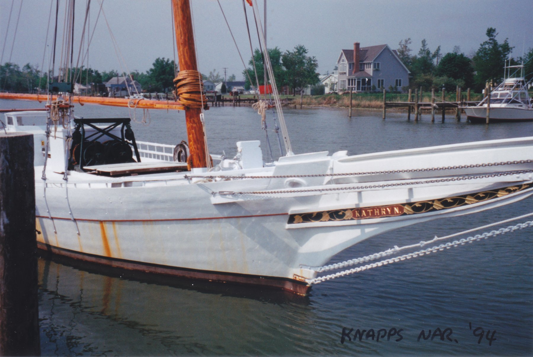
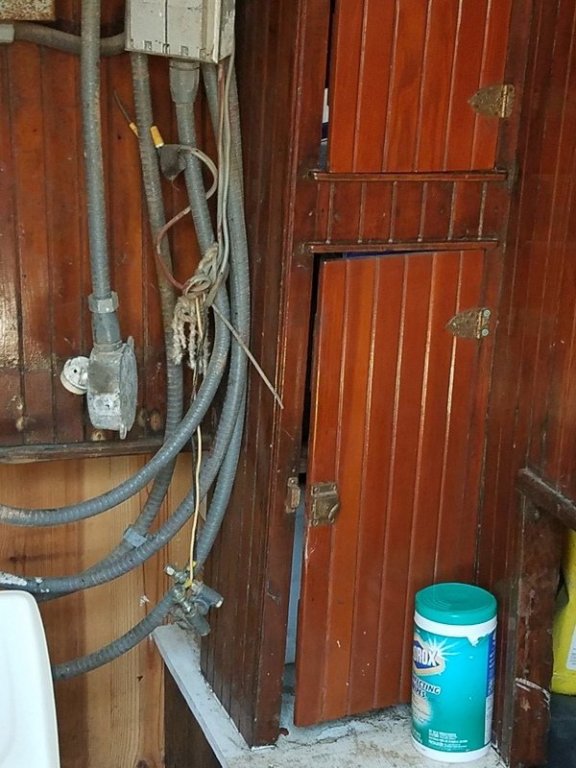
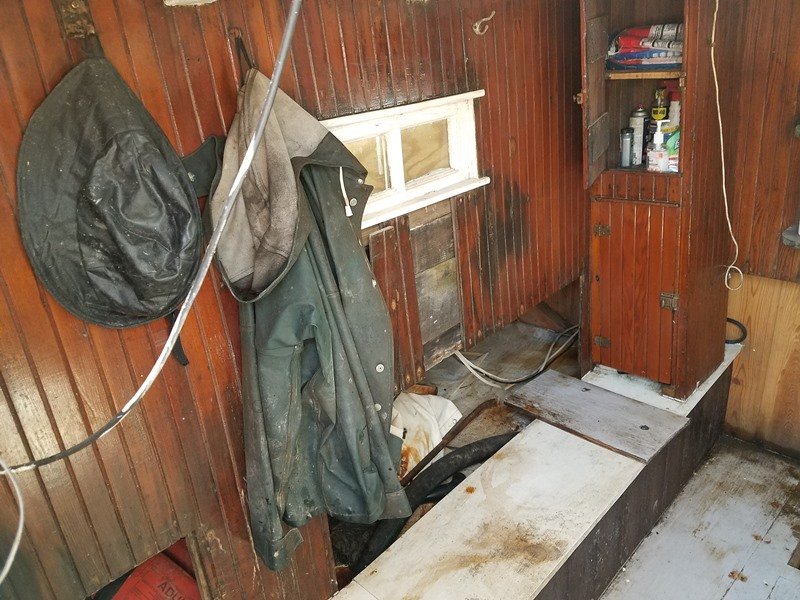
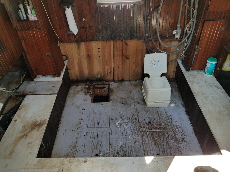
Thanks Druxey! Yeah, if I made her look like she does today, I'd have to not only include the electrical tape, but I'd need to strew lines and electrical cables around the deck. The small crew works really hard and doesn't have time (or skills, I think) to keep her ship-shape. I don't recall if I ever showed photos of what her cabin looks like today, but if not here's a few.
- 878 replies
-
- 12
-
-
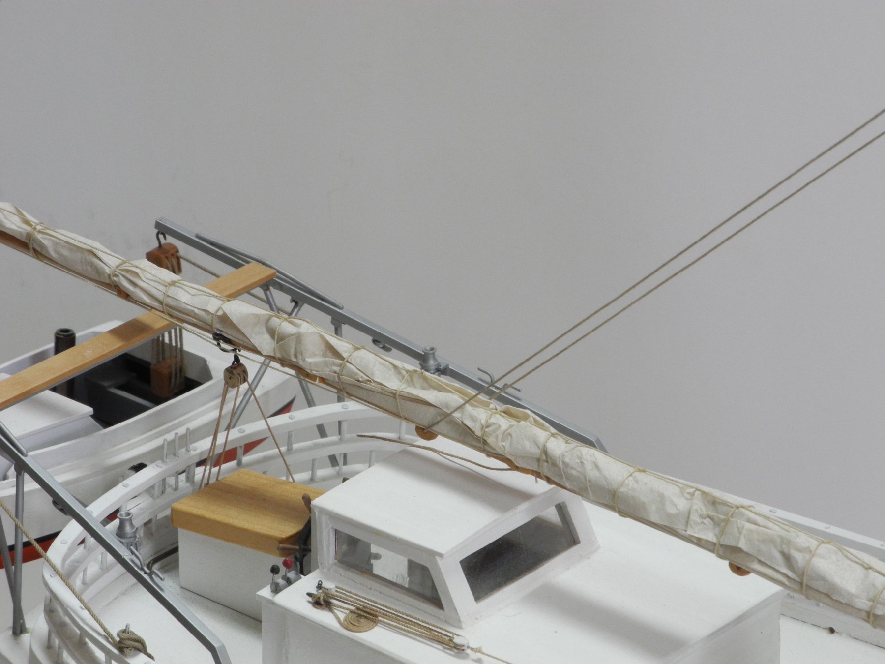
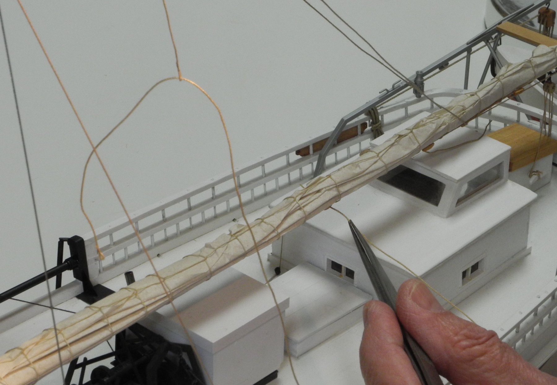
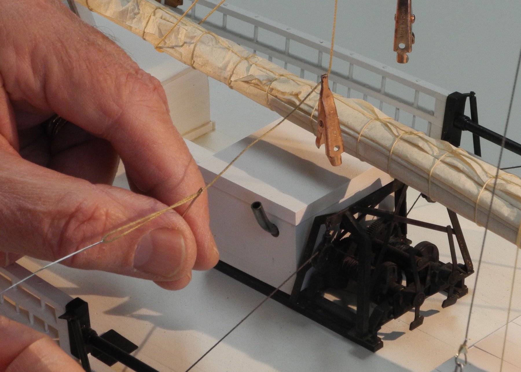
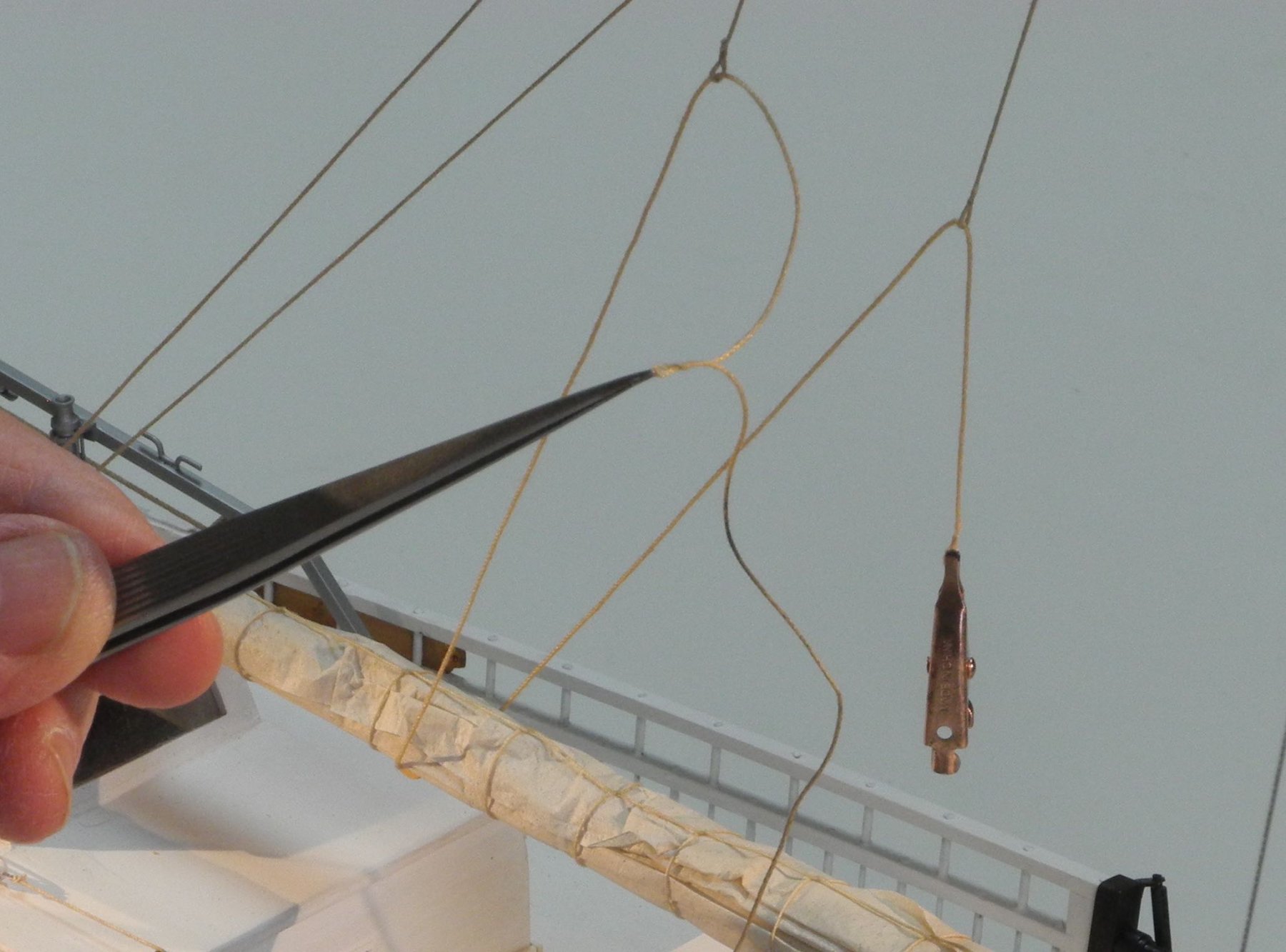
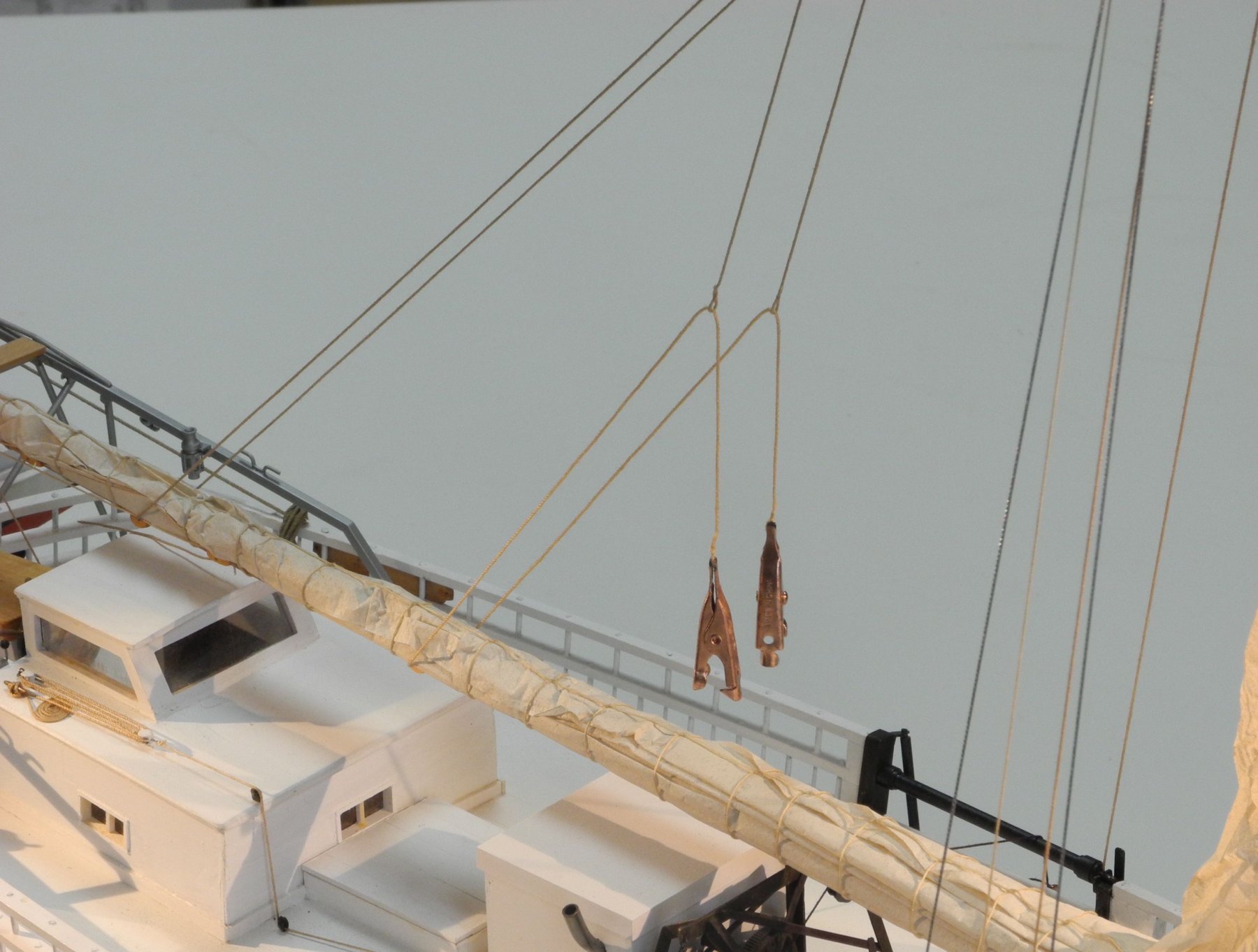
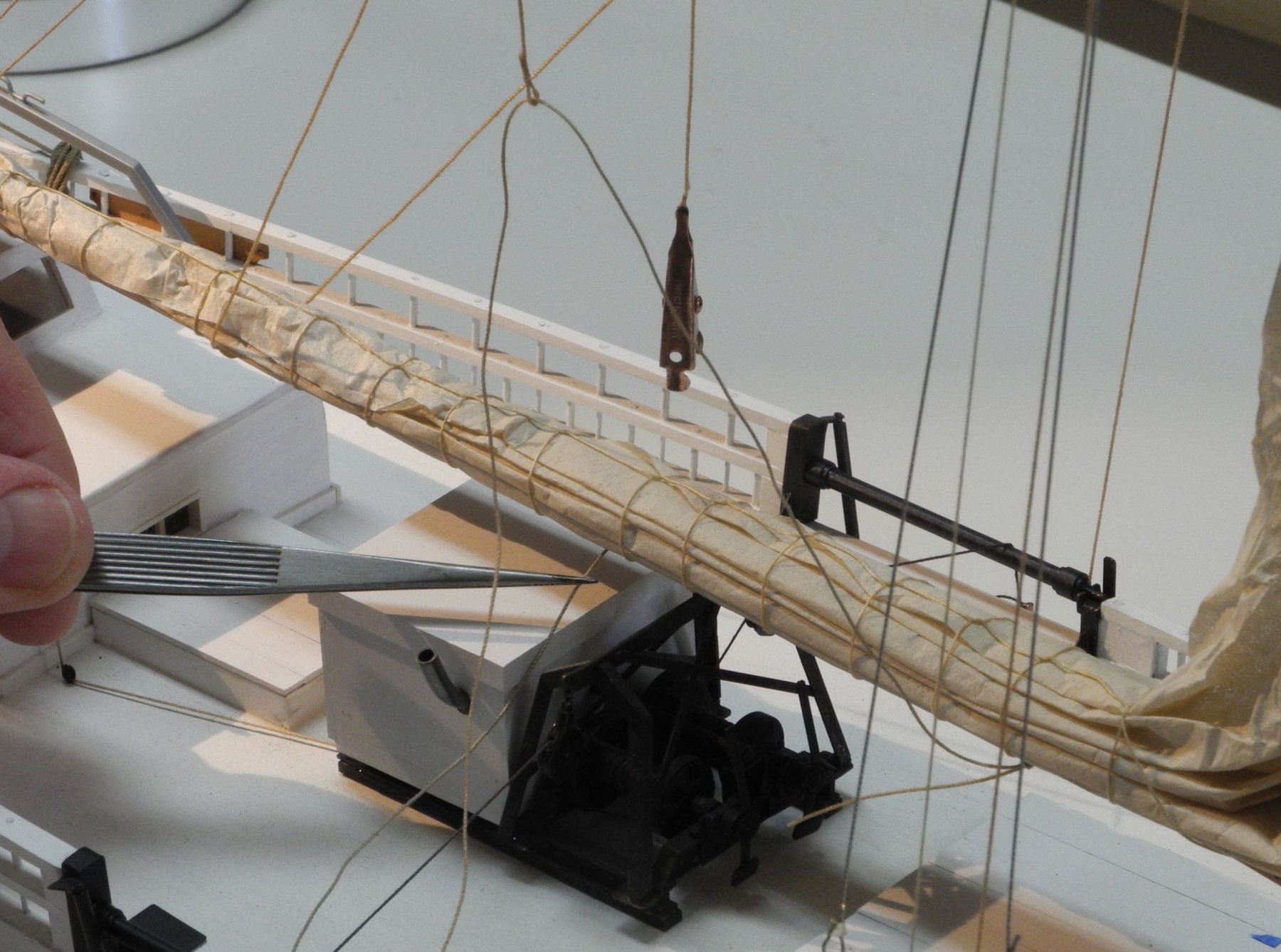
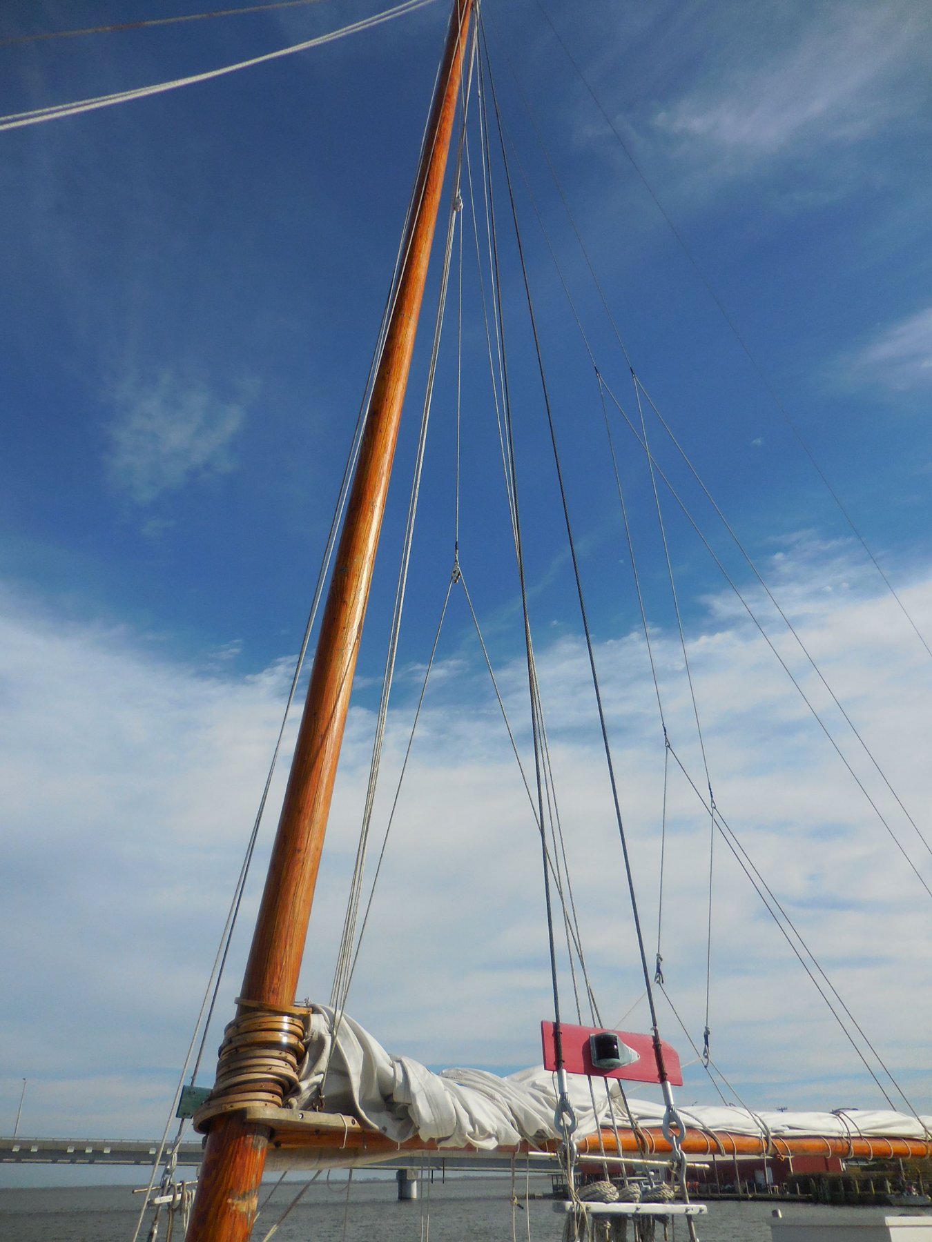
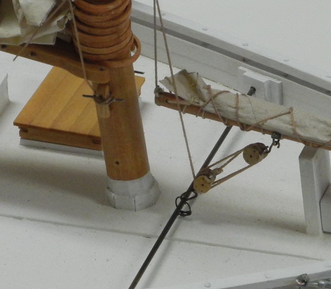
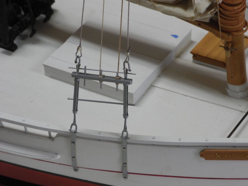
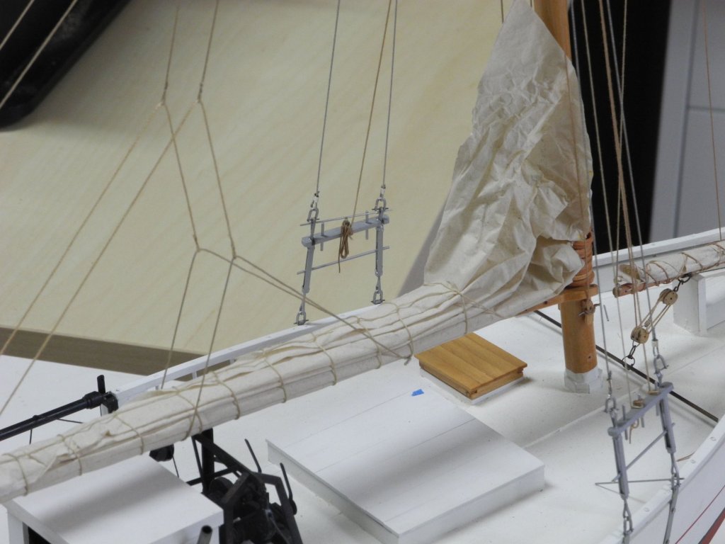
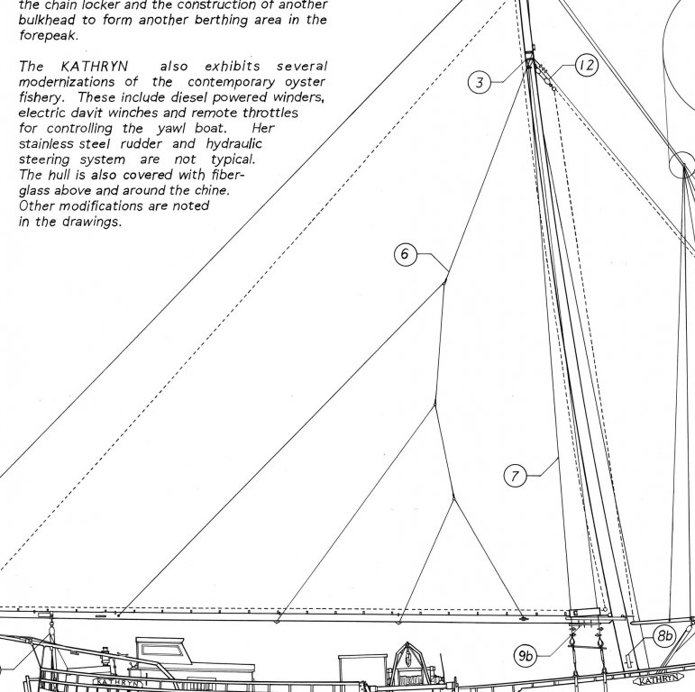
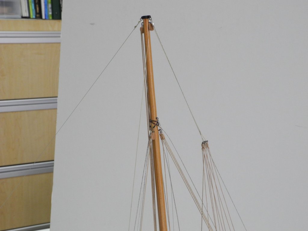
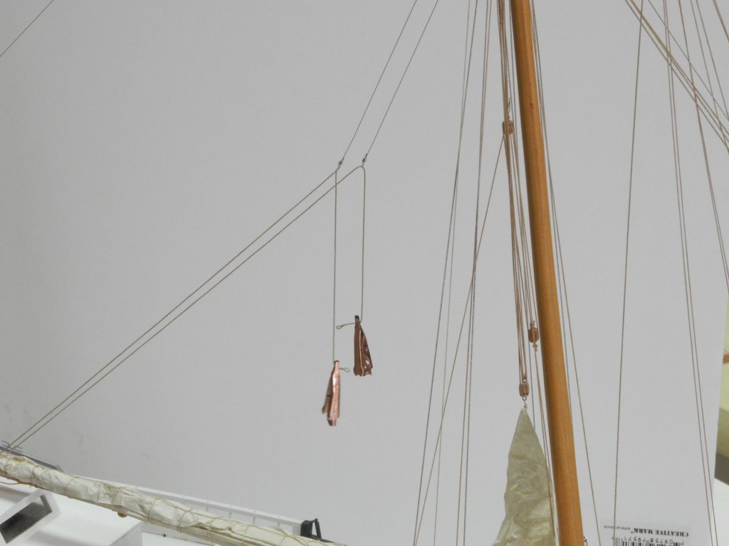
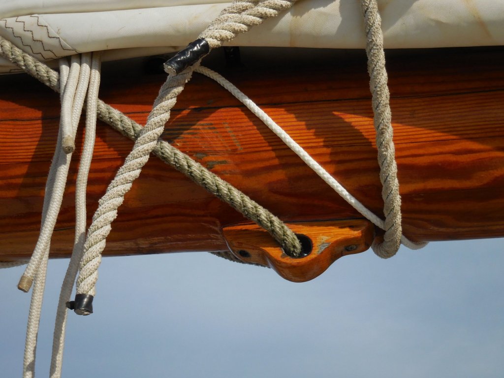
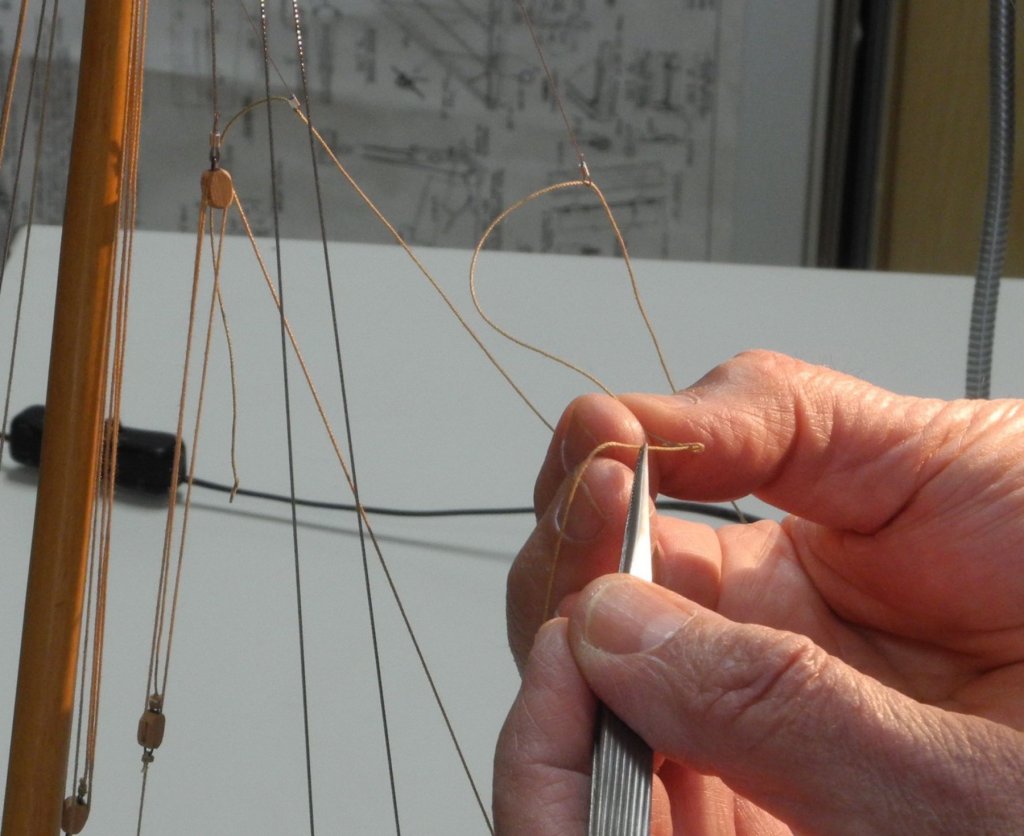
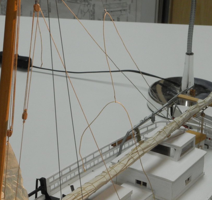
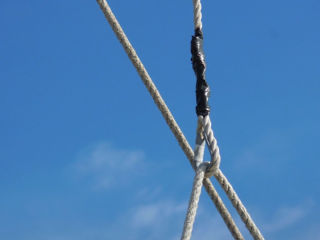
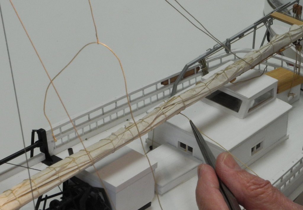
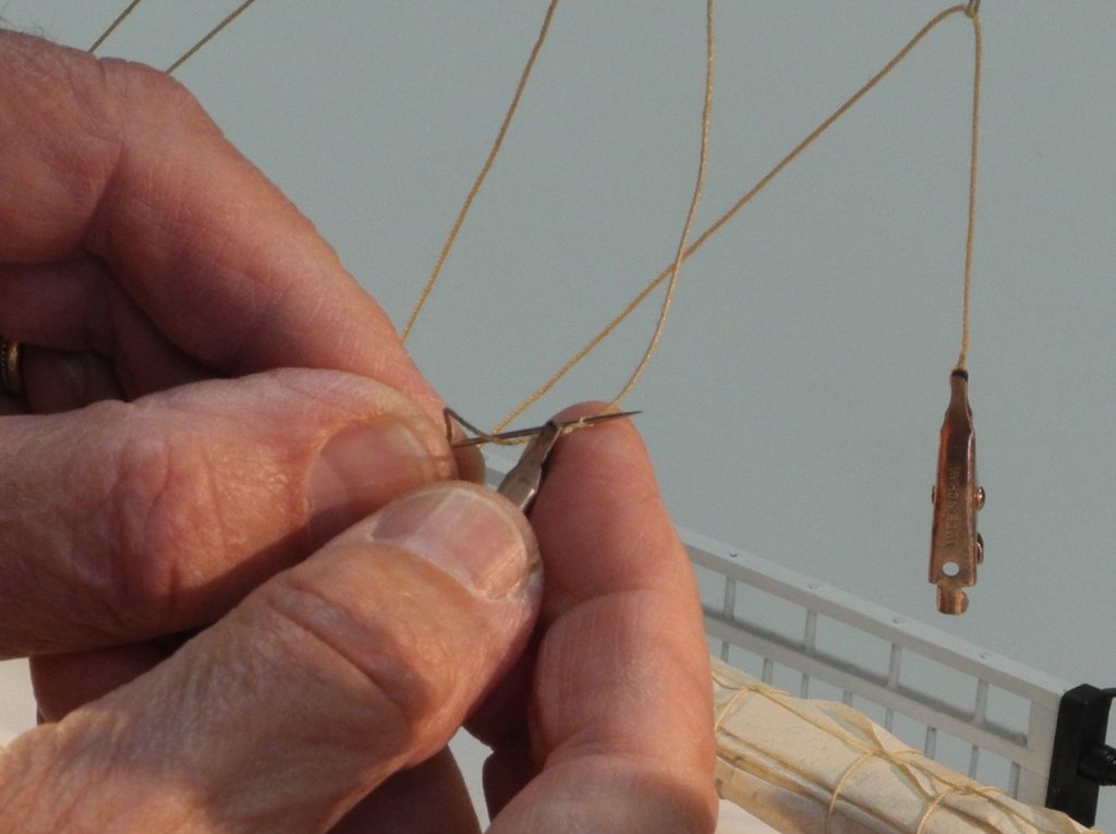
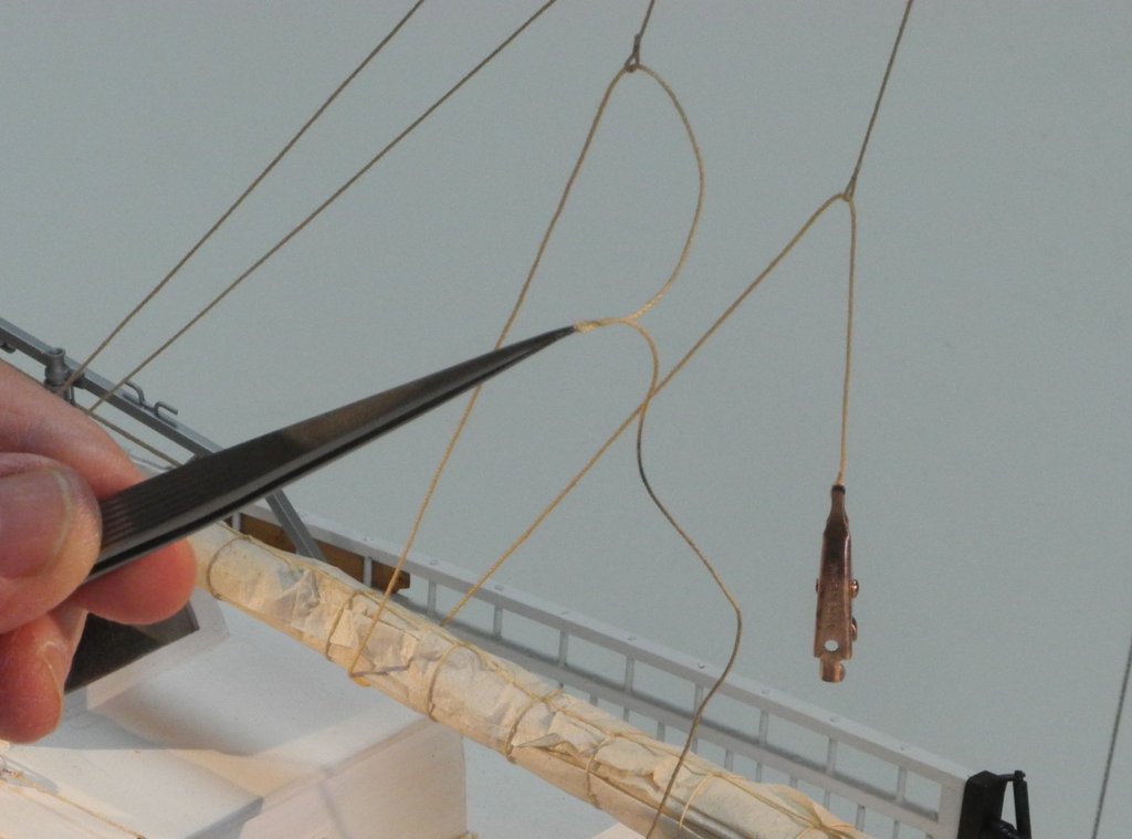
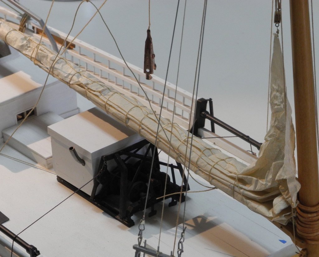
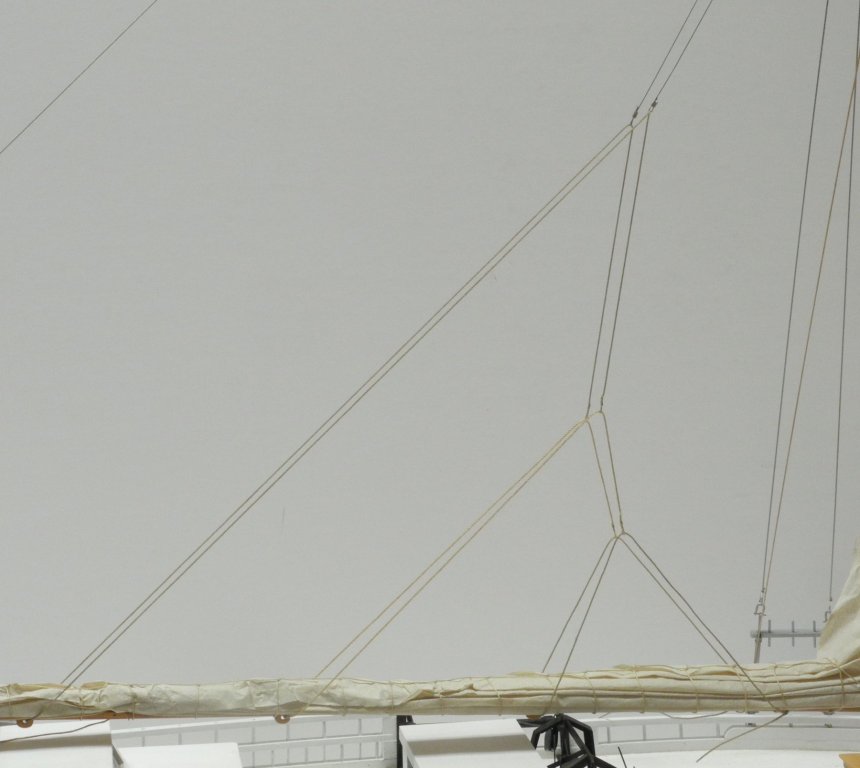
Part 94 –Mainsail Lazy Jacks The Lazy Jacks for the Mainsail are hung from steel wire pendants attached at the hounds. The Lazy Jacks are interconnected via hoops spliced into the ends of the individual lines, forming what I would describe as a ‘web’ of lines, as in the following drawing from the HAER documentation and a photo of Kathryn taken in 2017. The pendant for the model was made from 20 LB uncoated steel fishing leader, run through an eyebolt and then crimped into small loops on each end. The eyebolt on the pendant was CA’d into a small hole bored just above the hounds on the forward side of the mast. The installation of the Lazy Jack lines started with the aftmost line, running it through the loop on one end of the pendant, through a fairlead under the boom, and then through the loop at the other end of the pendant. The following photo shows one of the fairleads for the Lazy Jacks on Kathryn. Each end of the Lazy Jack line has a loop spliced into the end of the line. One loop could be spliced on the end of a line before the line was threaded through the pendant loop, through the fairlead, and then through the second pendant loop. The loop at the other end of the line could only be spliced after the line had been run through all of these points. Splicing the line when it had already been run onto the model was a little delicate. The following sequence of photos shows how this was done for the second Lazy Jack line. First, a loop was spliced onto one end of the line. Then the other end of the line was run through the existing loop on the port side of the rear Lazy Jack. The loops on Kathryn’s Lazy Jack lines contain small thimbles, but these would have been approximately 1/64” on the model so were omitted. (note the ‘splice’ on the loop in the following photo) The line was fed through the fairlead on the bottom side of the boom. and then through the loop at the other end of the aft Lazy Jack. The end of the line was then threaded though the eye of a medium sized needle (the needle was large enough to accommodate the .016” line used for the Lazy Jacks) The splice was made by passing the line through itself twice and was finished off by applying a small drop of white glue and rolling the splice through the fingers for final shaping. The use of the sewing needle made the splice strong enough to resist any pressure that would result from tightening the lines through the loops. The forward-most of the three Lazy Jack lines was started by seizing it to the forward cleat on the starboard side of the boom, then running it through the starboard loop on the second Lazy Jack line. The line was then fed through the forward fairlead under the boom and through the loop on the port side of the second Lazy Jack line, and finally was tied off at the boom’s forward port cleat. The end of this line has not yet been fully secured, since some adjustments will need to be made to get the Lazy Jacks symmetrical. The Lazy Jacks on the real Kathryn are not lined up very well, but the model’s appearance does require the lines to be pleasing to the eye. So this where the Kathryn model now stands, with the rigging complete. There is still some cleanup and rigging adjustment required, and some small items that need to be installed. I’m going to focus on getting all of that completed before work begins on the (dreaded) dredges.


- 878 replies
-
- 18
-
-
Good point, Mark. I would think that if the lazyjacks were taut it would inhibit the natural shape of the sail when under way. The spectacle iron can be lowered to loosen the jib lazyjacks, but since the lazyjacks for the main sail don't have a mechanism to allow them to be lowered I would assume that raising the boom would allow them to loosen.
-
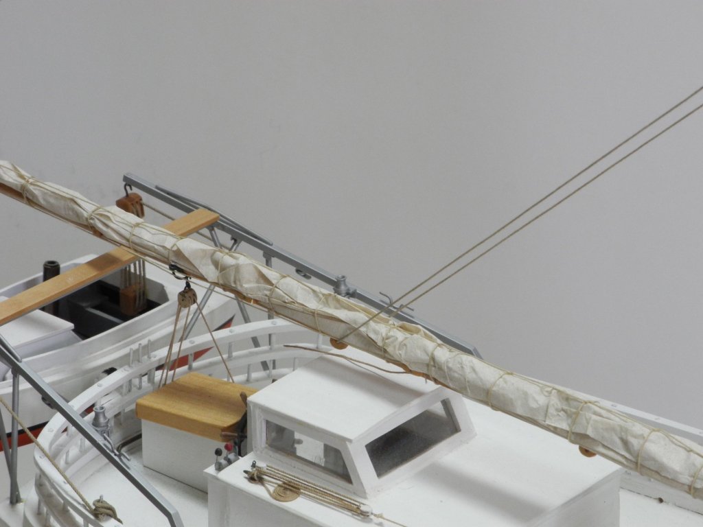
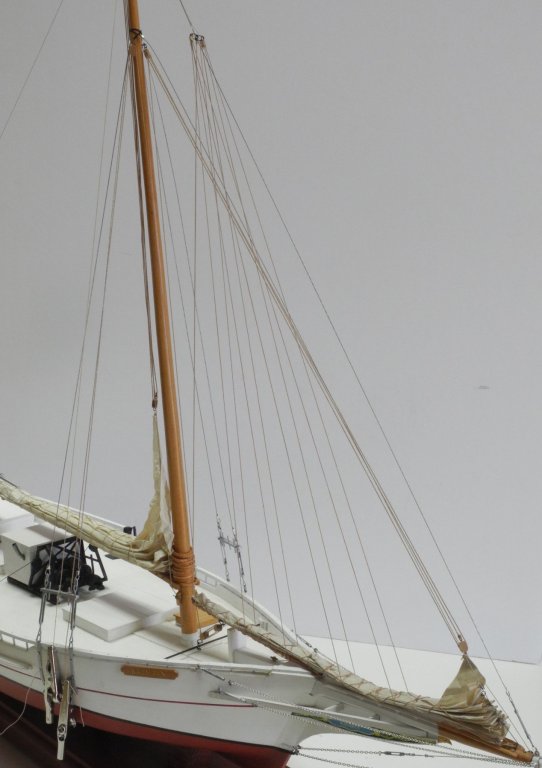
Hi Rob and Mark. Here's a description of Lazy Jacks from Wikipedia that may help: "Lazy jacks (or lazyjacks) are a type of rigging which can be applied to a fore-and-aft rigged sail to assist in sail handling during reefing and furling.[1] They consist of a network of cordage which is rigged to a point on the mast and to a series of points on either side of the boom; these lines form a cradle which helps to guide the sail onto the boom when it is lowered, reducing the crew needed to secure the sail. Lazy jacks are most commonly associated with Bermuda rigged sails, although they can be used with gaff rigged sails and with club-footed jibs. Blocks and rings may be part of some lazyjacks.[2] The oyster dredging sailboats of the Chesapeake Bay, bugeyes and skipjacks, were inevitably equipped with lazy jacks, as their huge sail plans, combined with the changeable conditions on the bay, made it necessary to be able to reef quickly and with a small crew. " The Lazy Jacks on the Kathryn are rigged a little differently from the description above - instead of being "rigged to a series of points on either side of the boom" they actually loop under the boom at several points. You'll see what I mean when I rig the Lazy Jacks for the Main Sail - hopefully soon. The Lazy Jacks for the Main Sail are left in place even when the sails are removed, whereas the Lazy Jacks for the jib are removed when the jib is removed. This is actually the main reason I put furled sails on the model - it allowed me to add the Lazy Jacks for the Jib. I felt that the front of the boat would look a little empty without them. Attached is a photo of the Kathryn with her sails removed which should illustrate my point.

- 878 replies
-
- 12
-
-
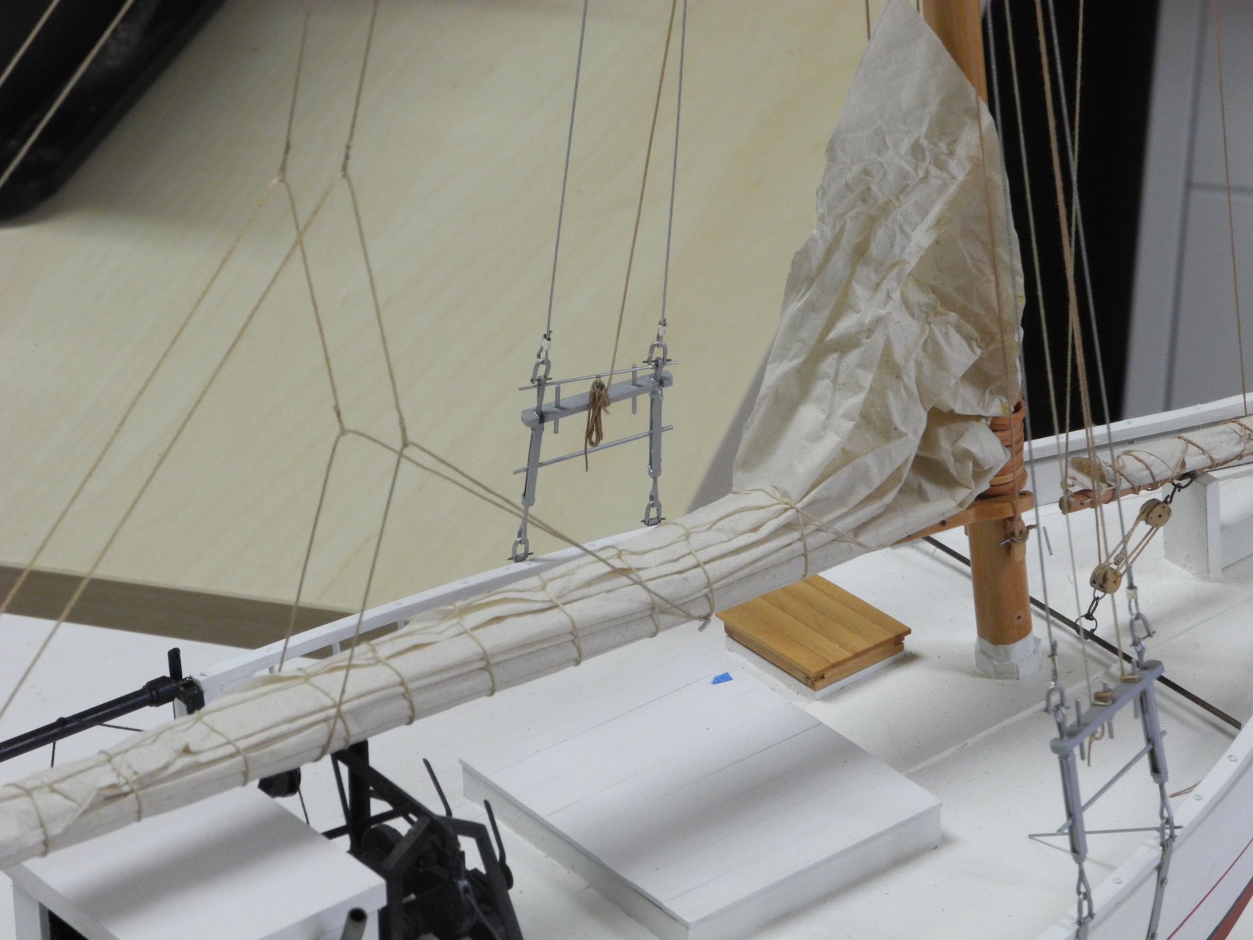
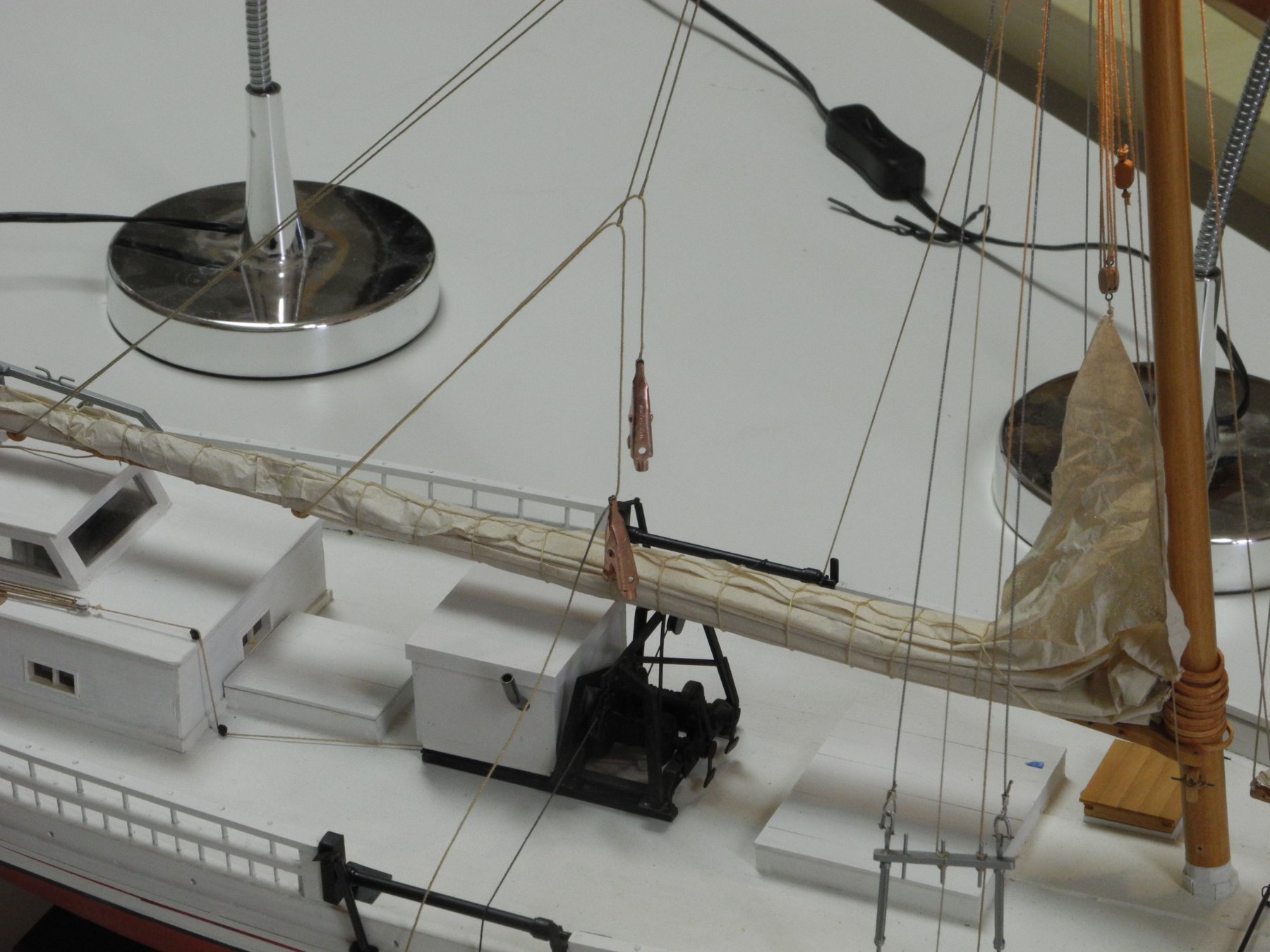
Part 93 –Jib Lazy Jacks Before the Jib’s Lazy Jacks could be installed, the Jib Club needed to be stabilized. The Jib Club Lift was seized to the middle ring of the Spectacle Iron. The hooked Jib Sheet block was attached to the bail on the Jib Club’s band, then the sheet was run between the two blocks, up to the single block at the hounds, and then down to the starboard pin rail. The sheet was temporarily secured in place, and the combination of the club lift and the sheet stabilized the Jib Club. The lines for the four Lazy Jacks were laid out. The aft two lines were run through holes in the Jib Club, and the forward two lines were run under the Jib and were tucked between the Jib’s wrapping line and the Jib itself – this will keep the two Lazy Jacks from moving from their locations on the jib. Working from aft forward, each Lazy Jack was seized to the outer rings of the Spectacle Iron, and after adjusting the two sides of the line for position and tension a small drop of white glue was used on each seizing to make it permanent. (I had tried installing all Lazy Jacks at once and then tensioning them, but this was problematic – two many lines in one place). The following photo shows the current status of the model – all Jib Lazy Jacks installed. The next task is to install the Main Lazy Jacks – a very different arrangement of lines.

- 878 replies
-
- 21
-
-
Hi Kurt. I don't keep track of hours, but I'd estimate somewhere between 1,500 and 2,000, based on a little math. Good thing I enjoy doing the work!