Mahuna
-
Posts
1,504 -
Joined
-
Last visited
Content Type
Profiles
Forums
Gallery
Events
Everything posted by Mahuna
-
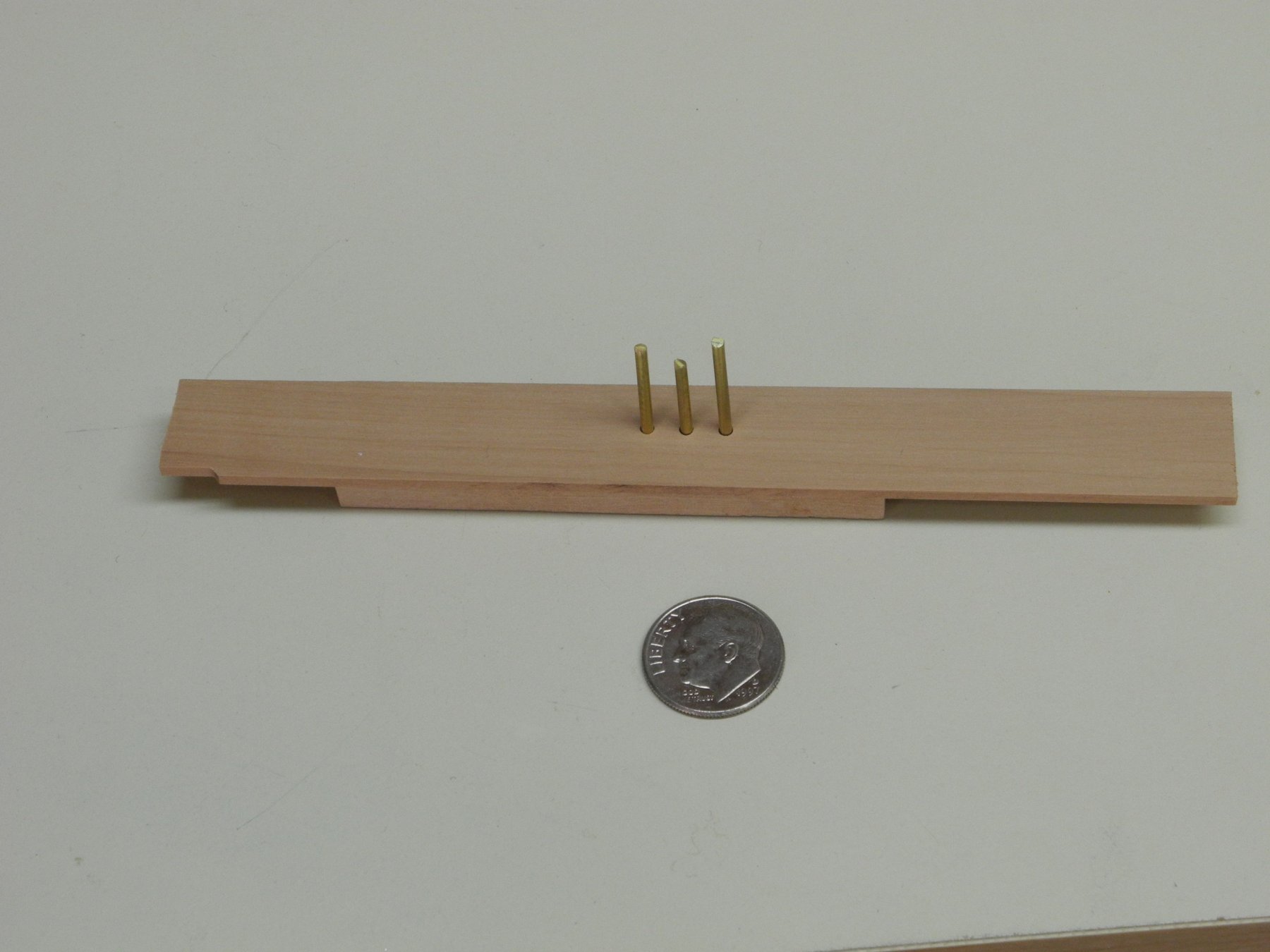
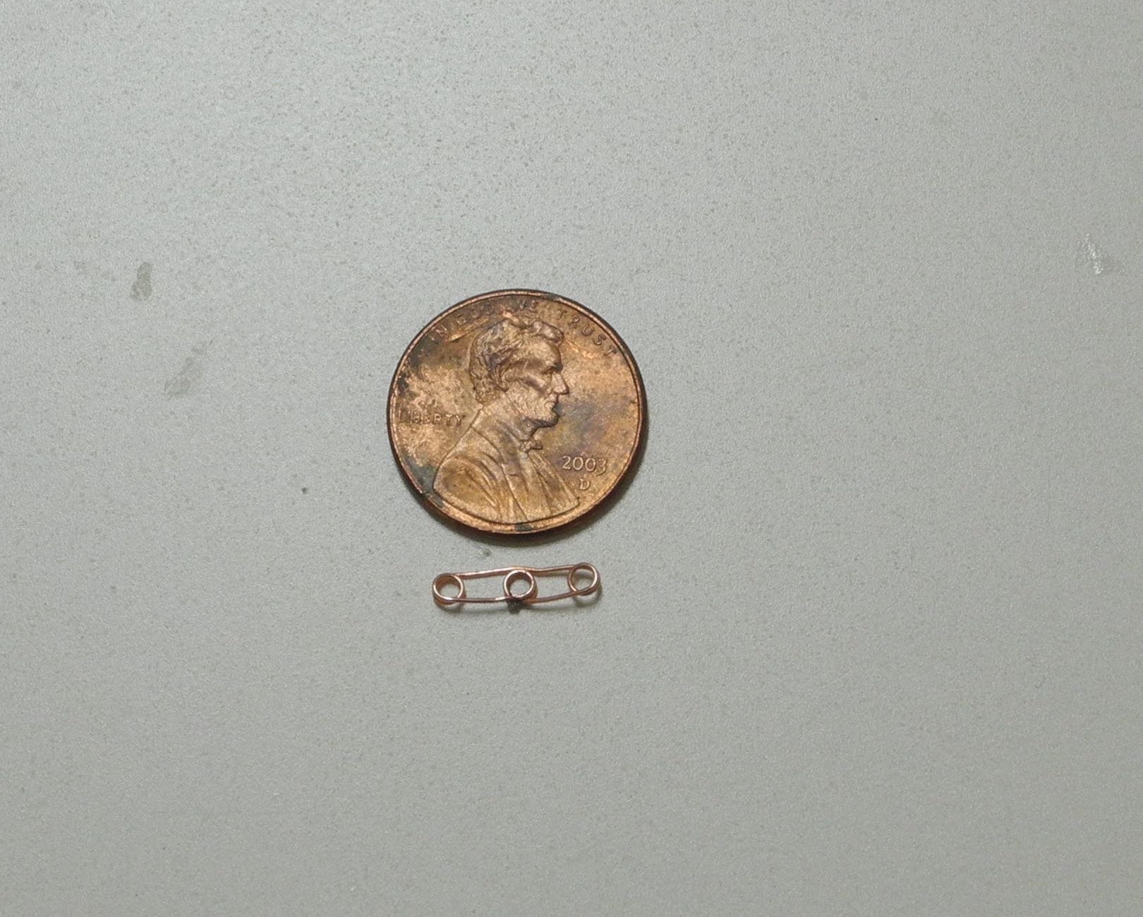
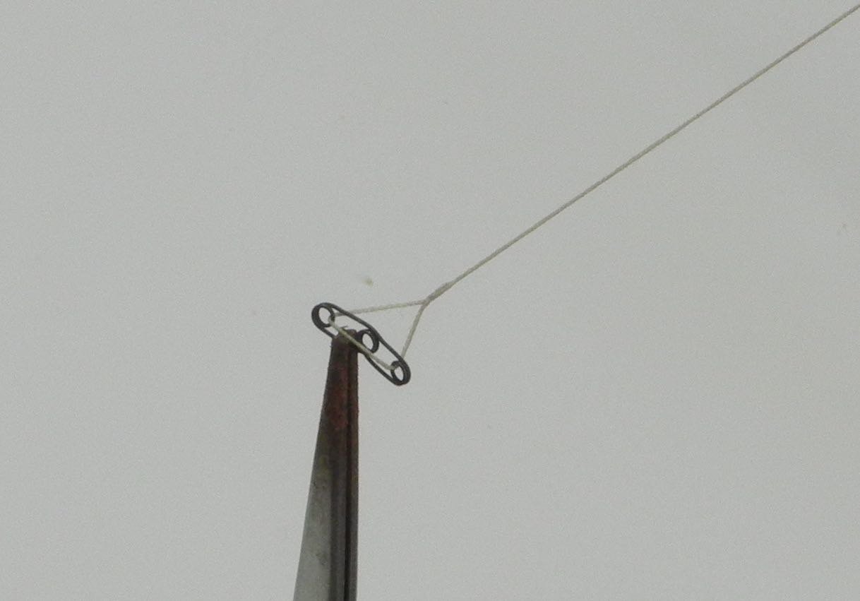
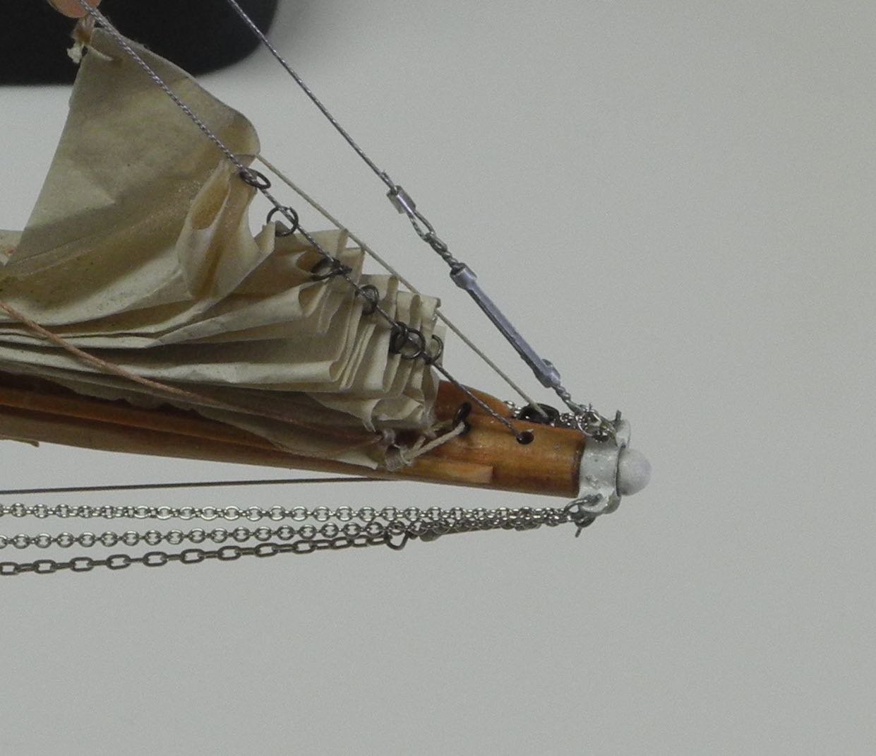
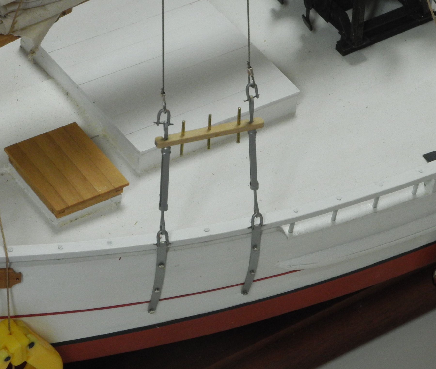
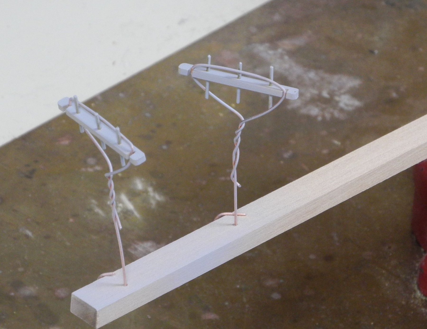
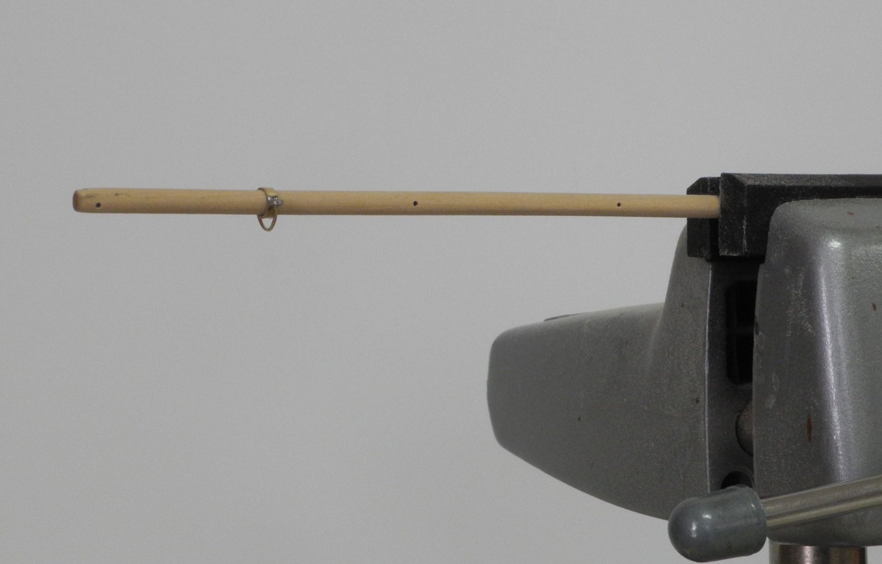
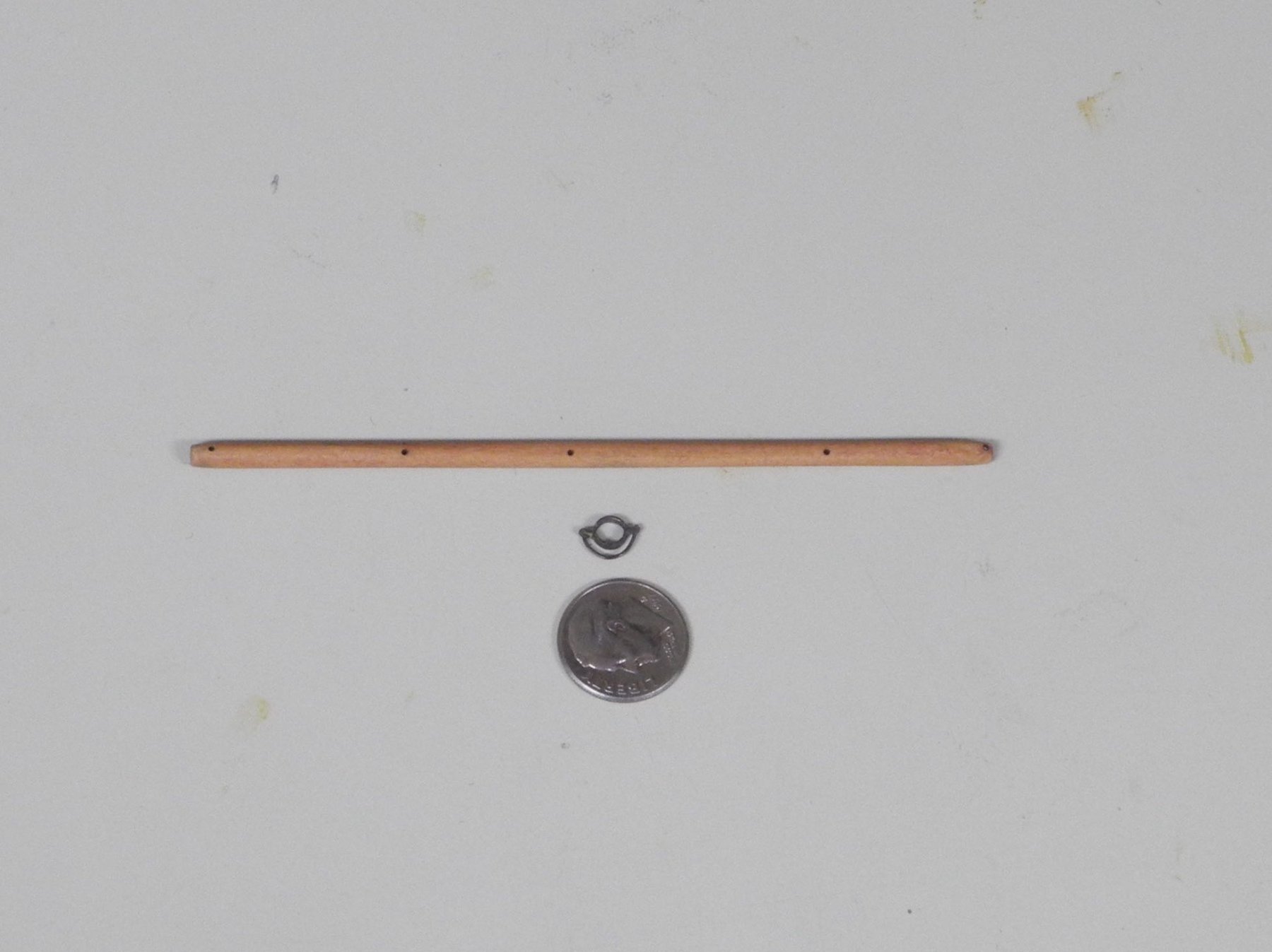
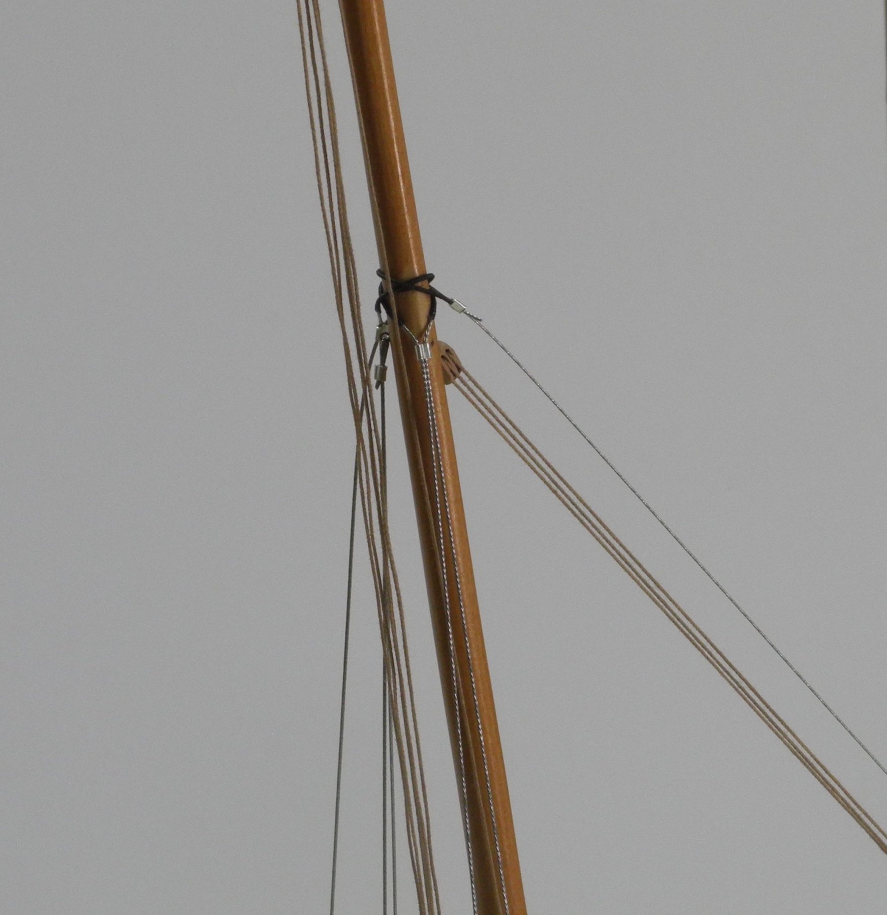
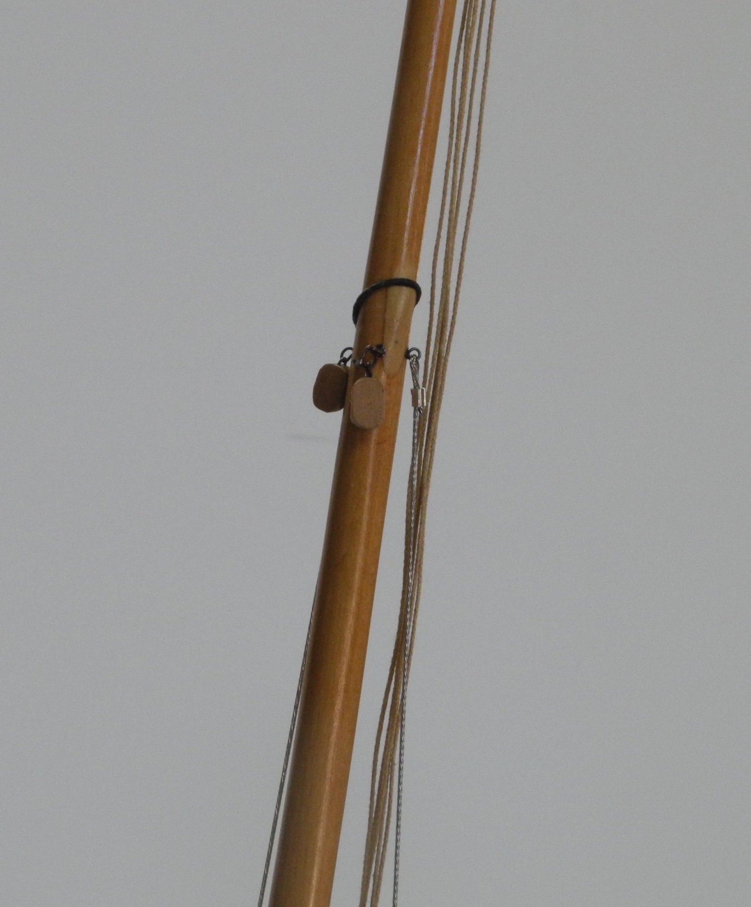
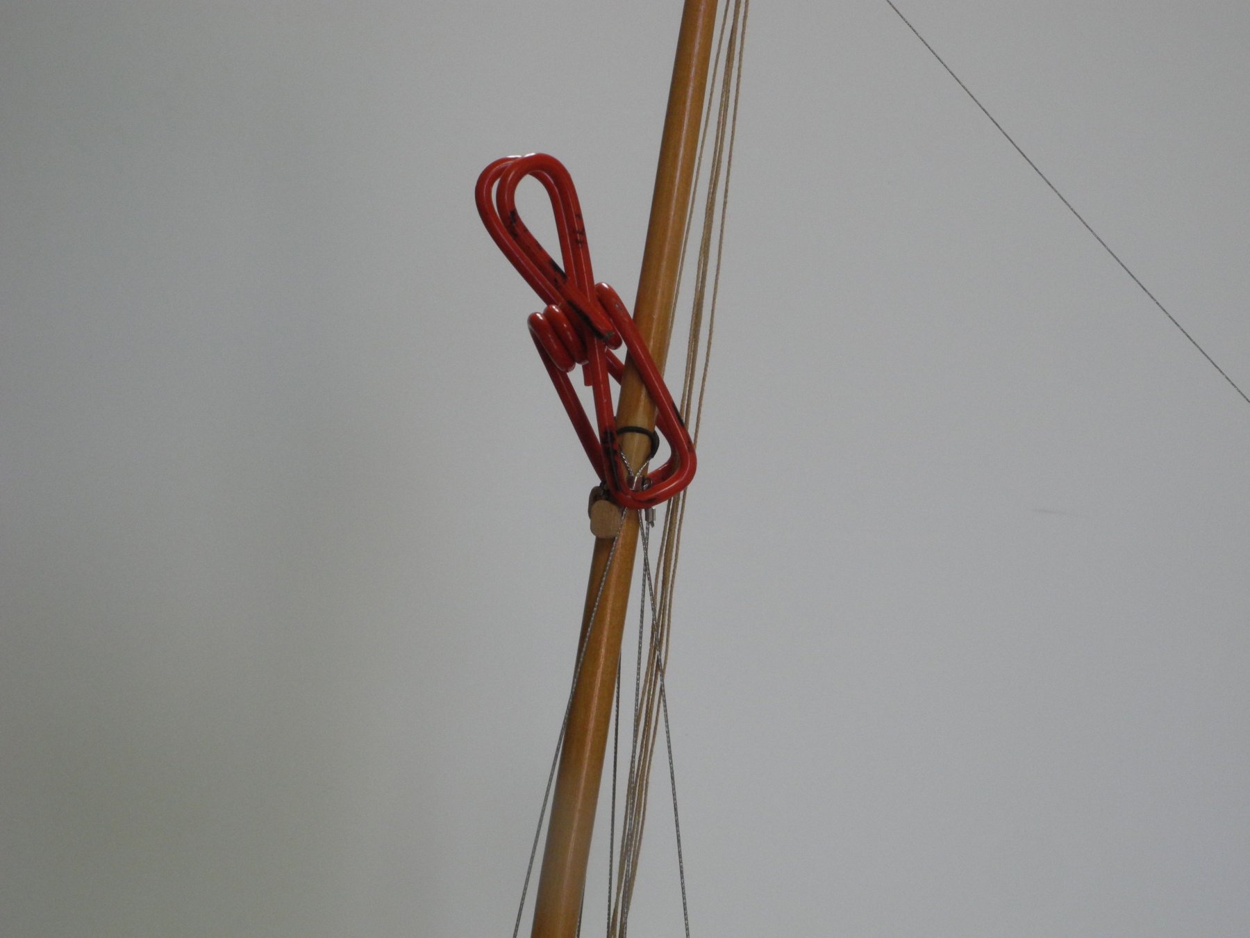
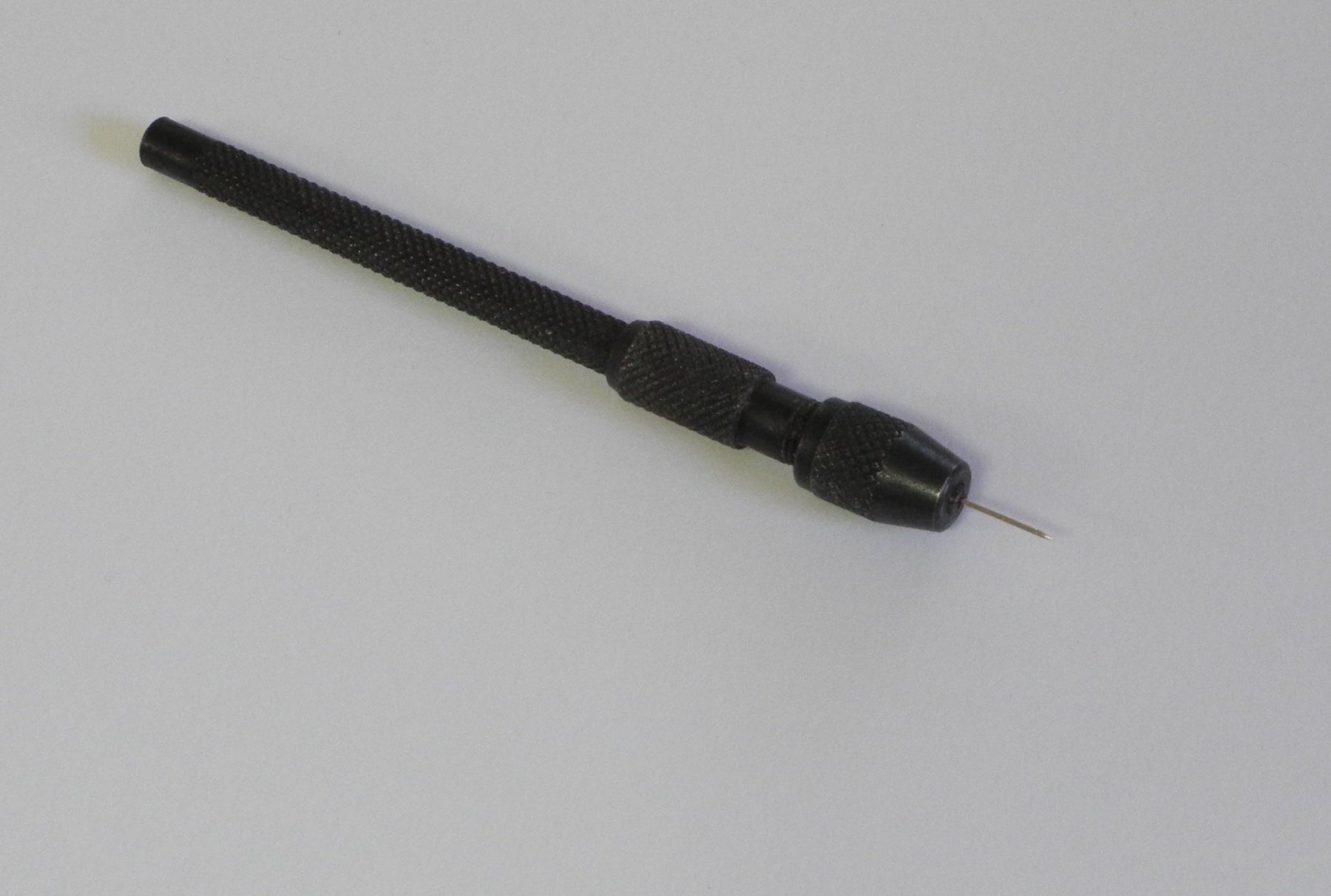
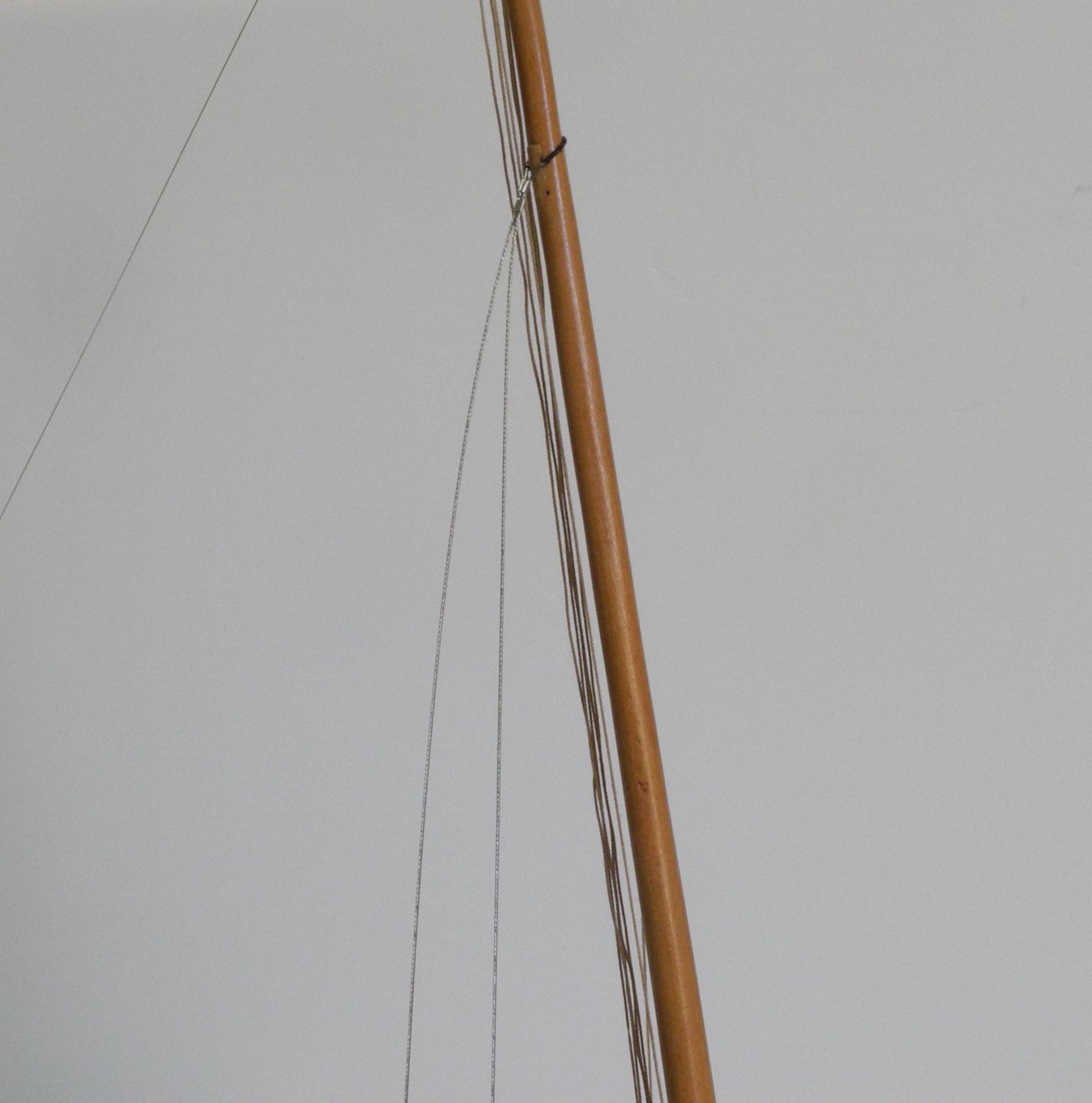
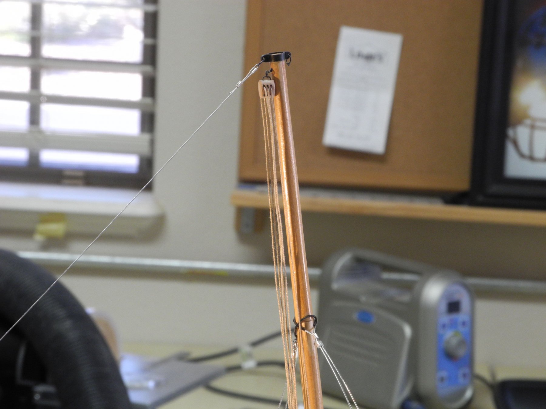
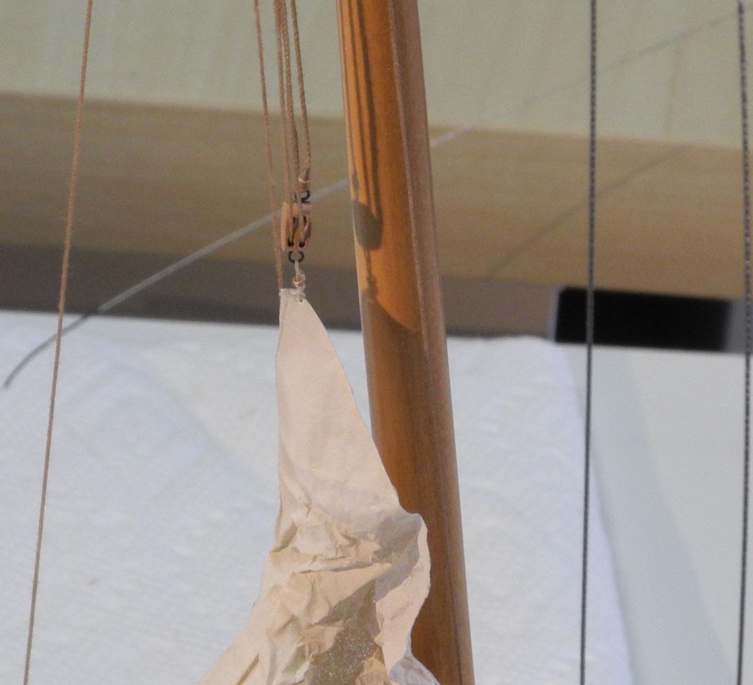
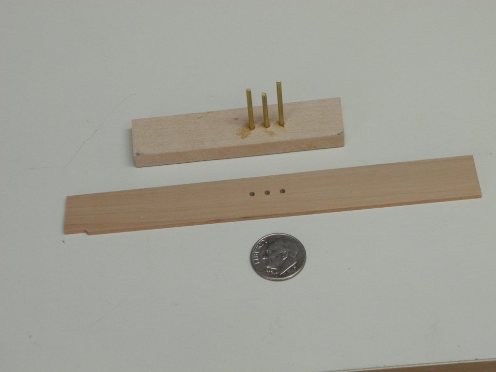
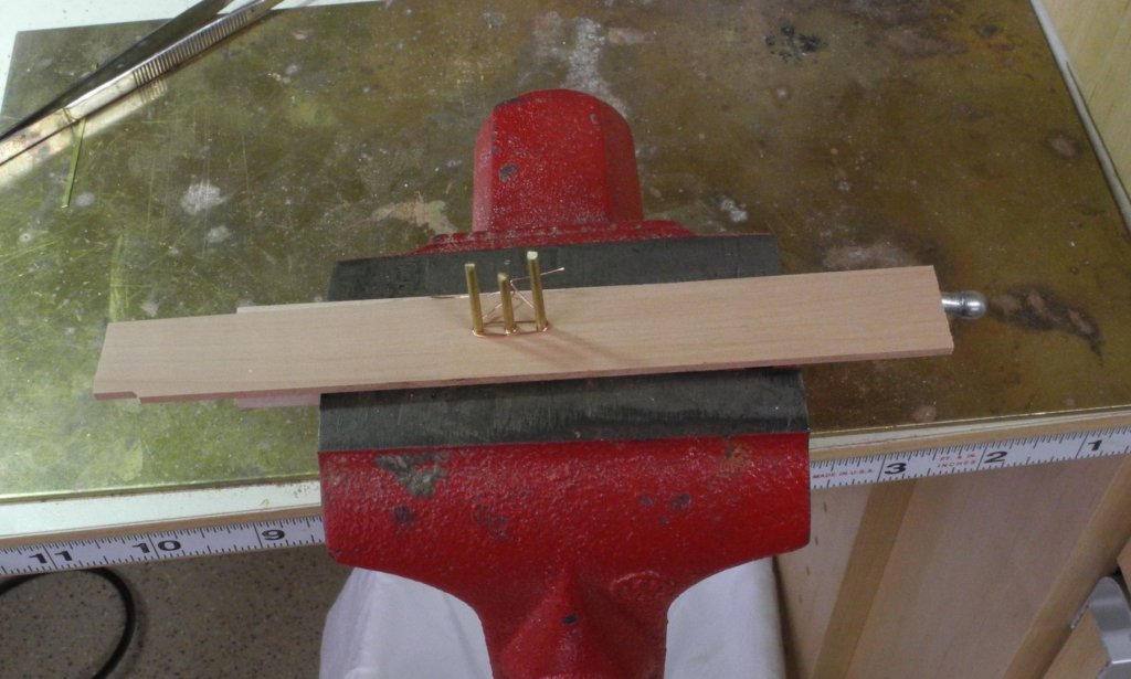
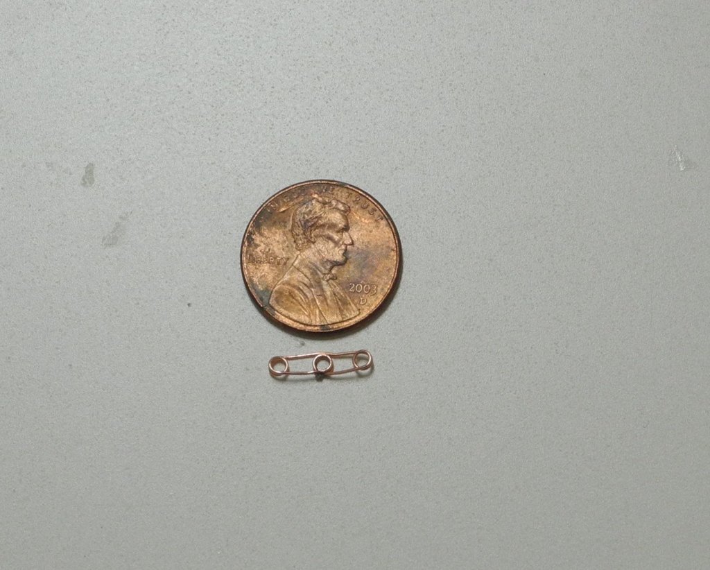
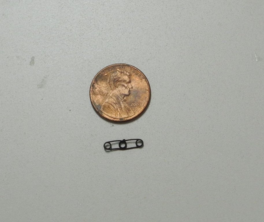
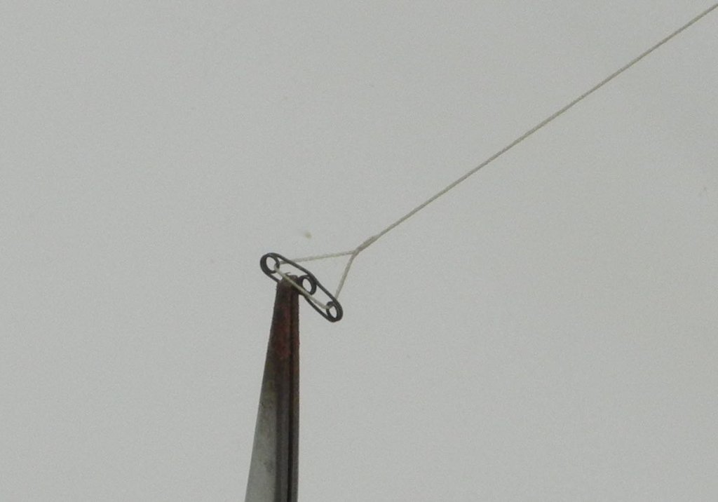
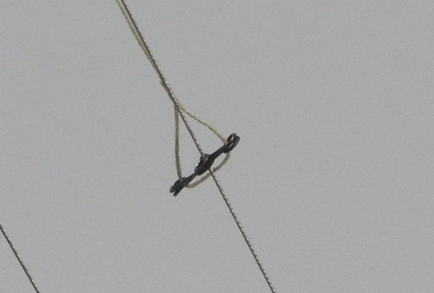
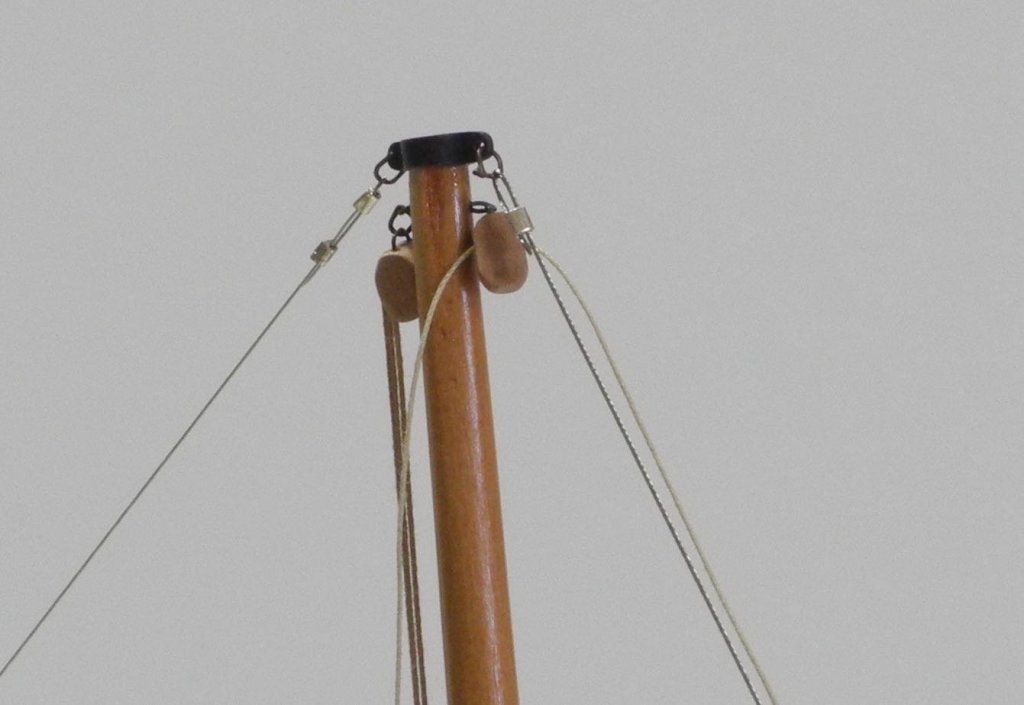
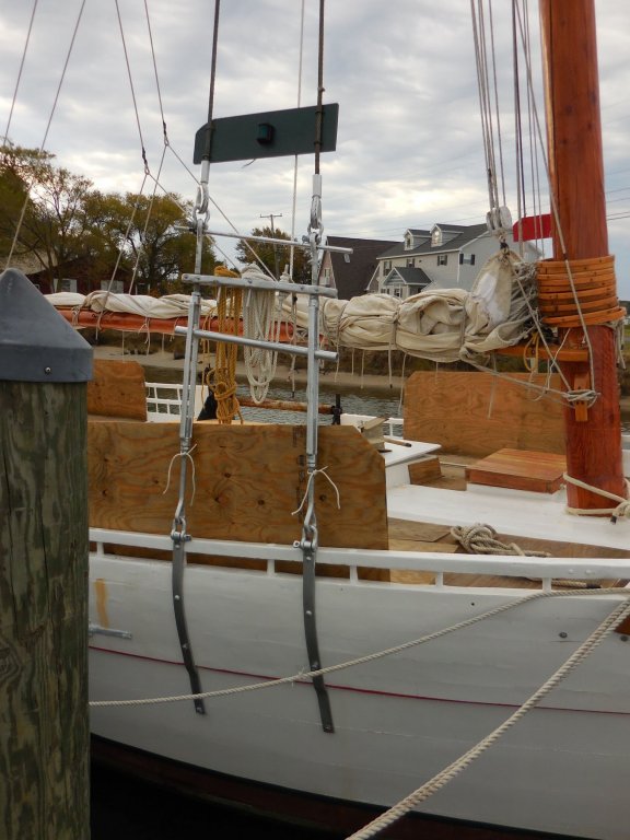
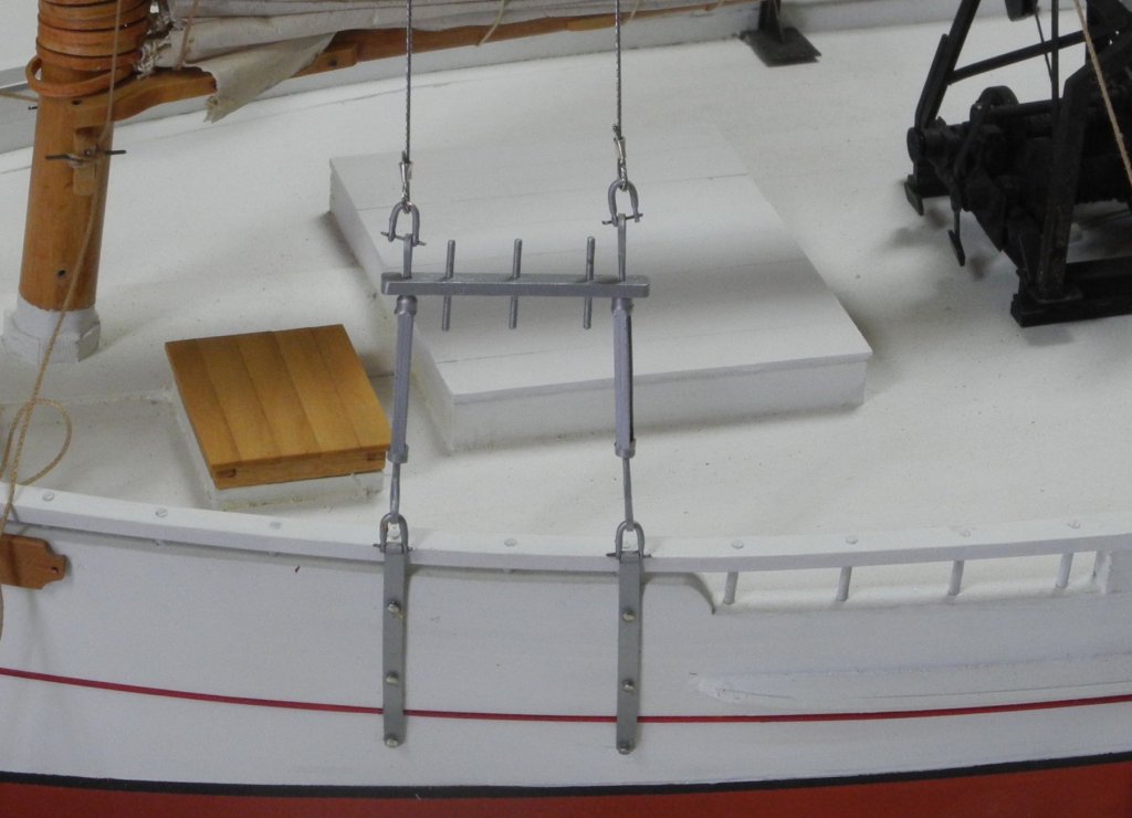
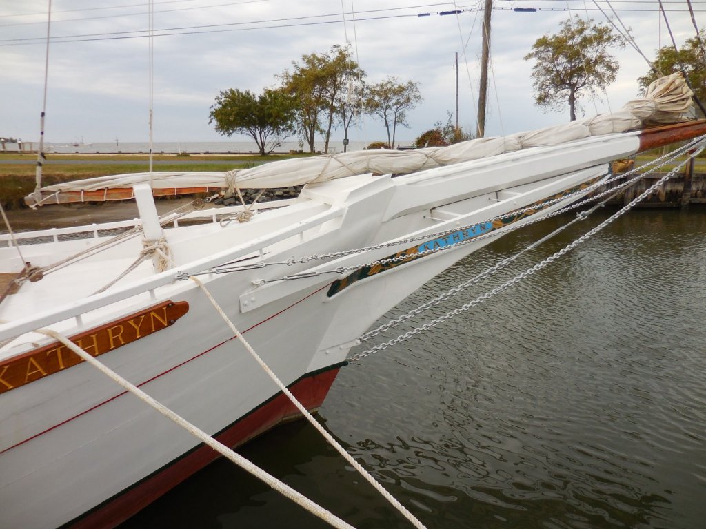
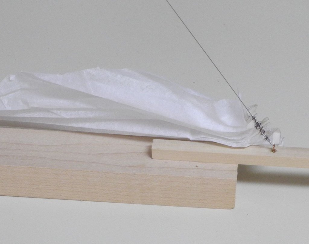
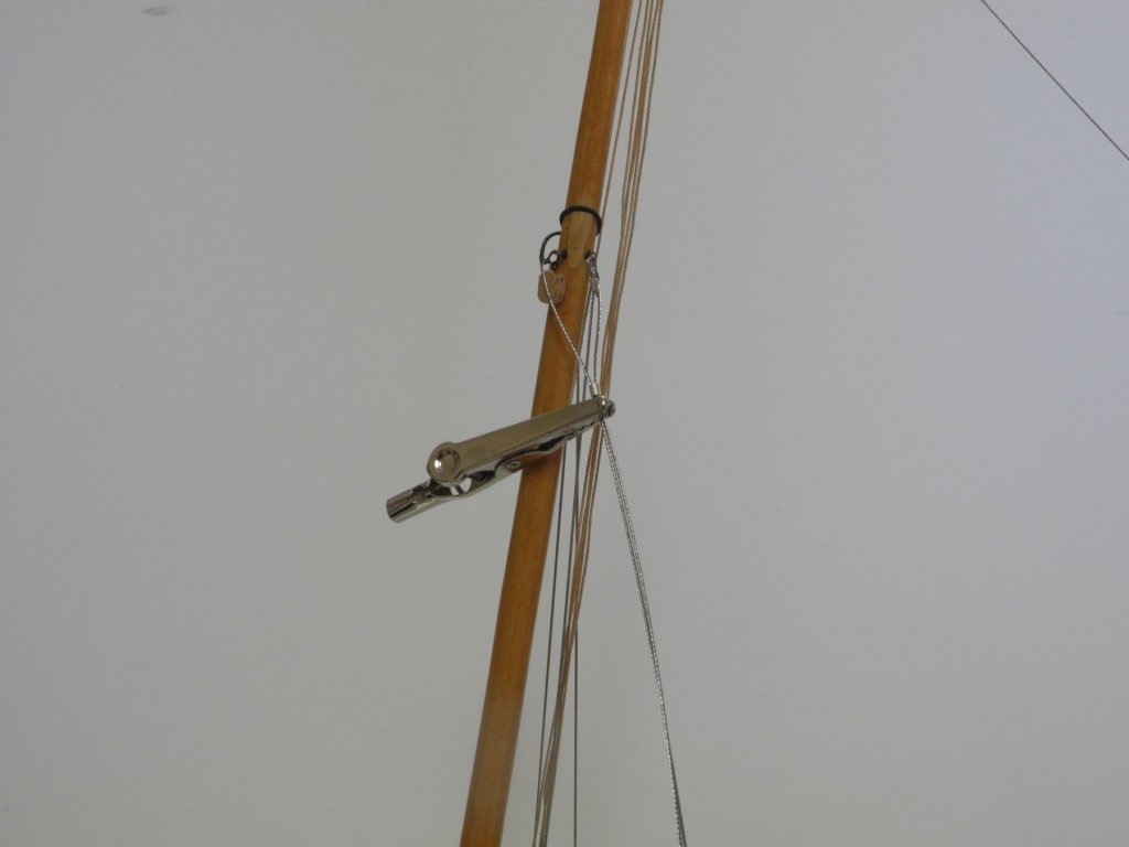
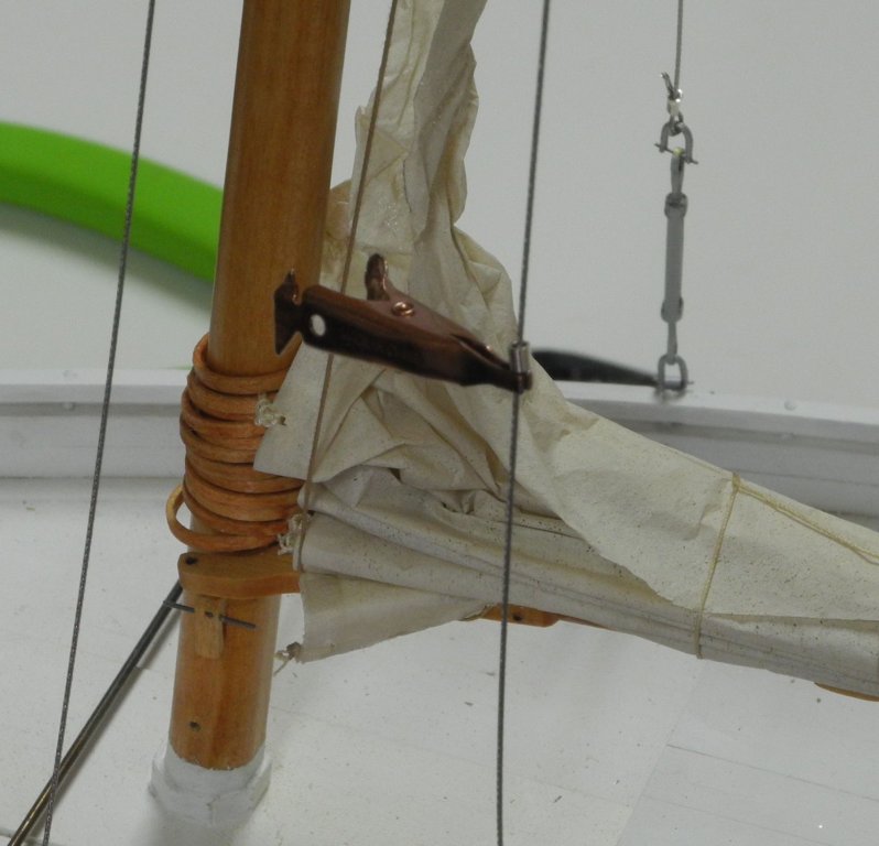
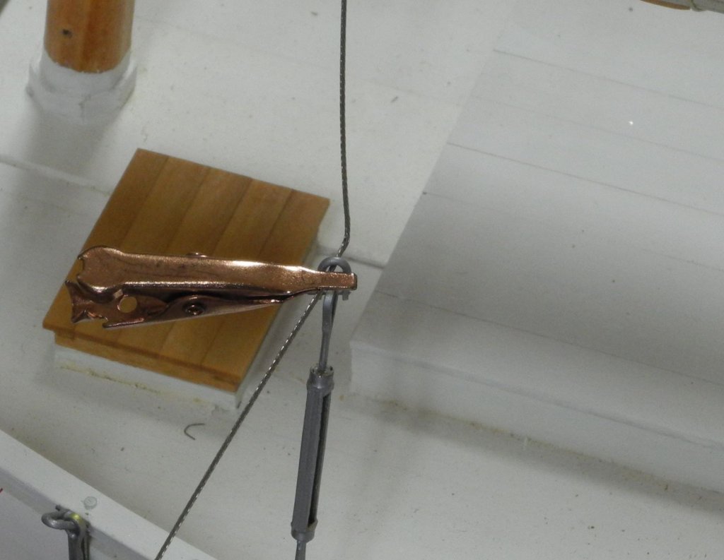
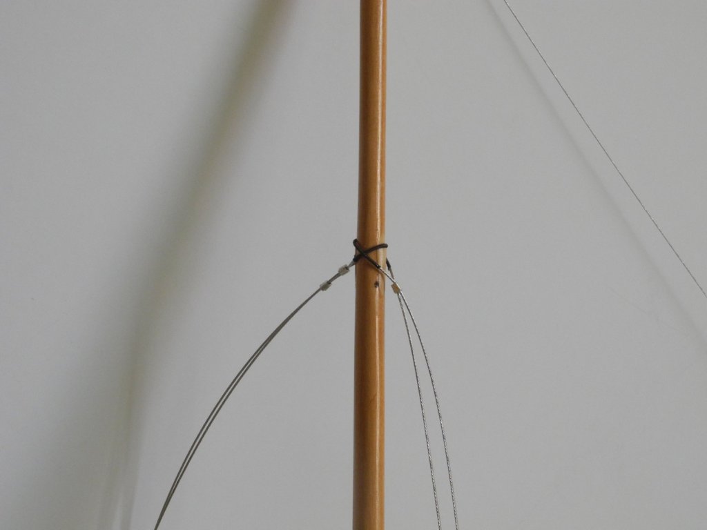
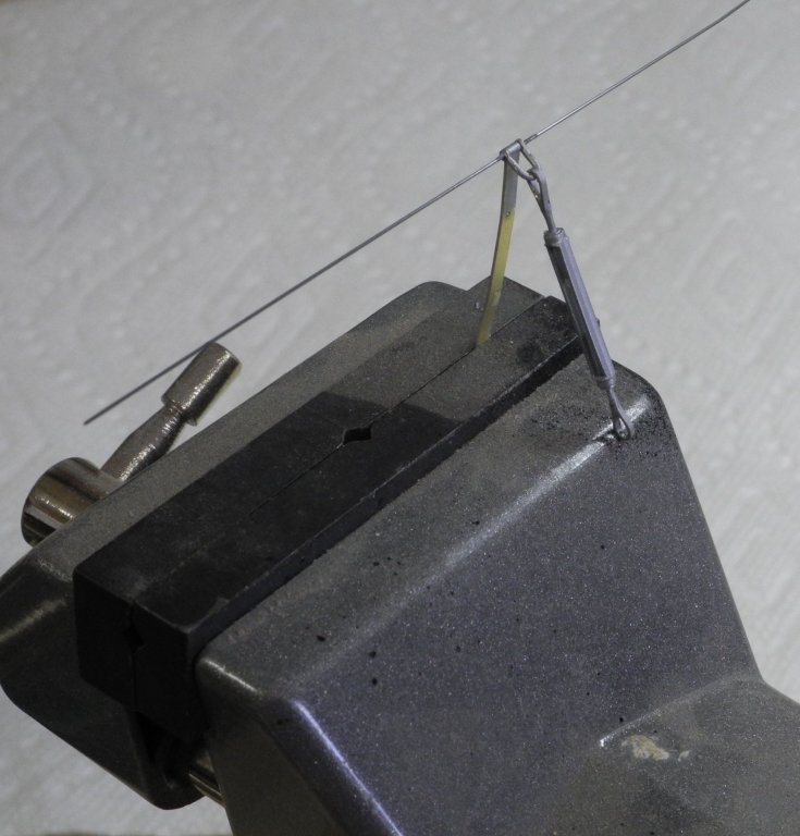
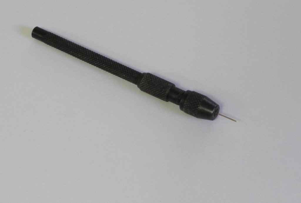
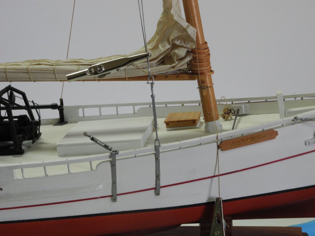
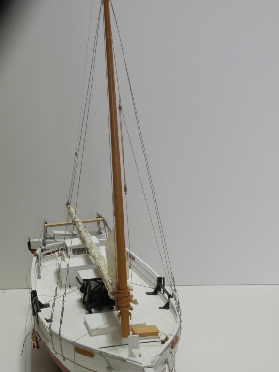
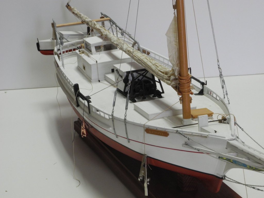
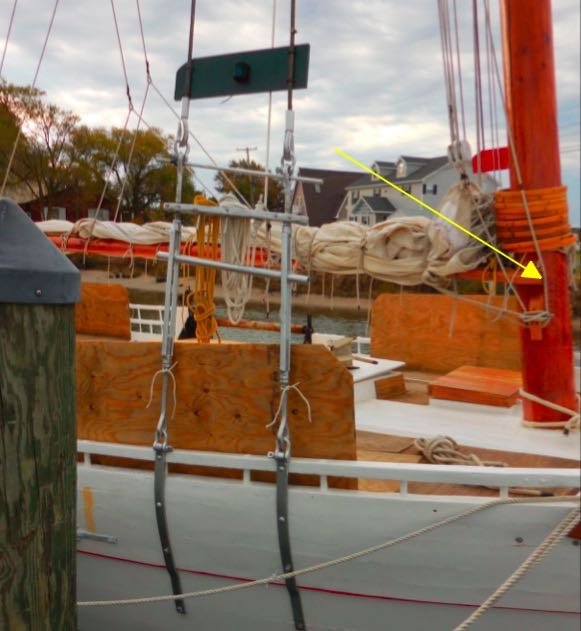
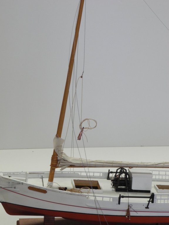
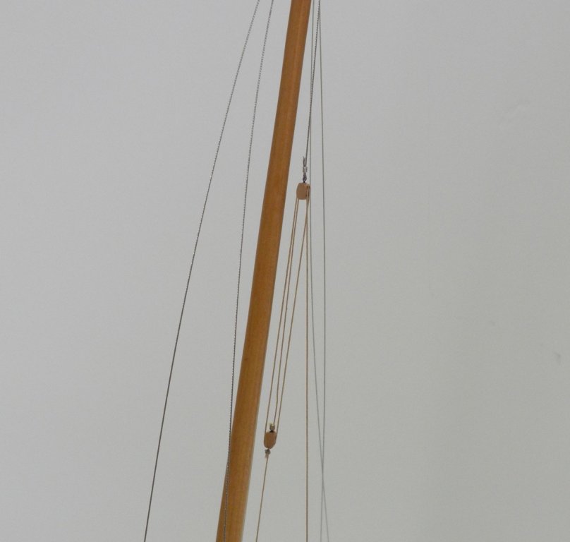
 Part 92 –Head Stay The following is the Haer drawing of Kathryn’s rigging, cropped to show the Head Stay and the Lazy Jacks supporting the Jib. Because the Lazy Jacks are so closely associated with the Head Stay, both need to be installed while mindful of the relationship. The first task was to develop the Spectacle Iron, which rides on the Head Stay and supports the Jib Club Lift and the Jib Lazy Jacks. This iron is fairly complex, yet is also fairly small. A jig was developed to form this iron. The jig consists of three 3/64” brass rods set into a block of wood, along with a cap that is drilled out to fit over these rods. The purpose of the cap is to provide a mechanism to lift the Spectacle Iron off the jig once it is formed. The iron was formed from 26 gauge copper wire, and was then blackened using JAX Pewter Black. The line for the Jack Lift was run through the two outer rings of the Spectacle Iron, and was then spliced to form a triangle. (The splicing method was the same used for the Reefing Tackles discussed in Part 83) The Head Stay is attached to the upper lug of the Bowsprit Band by a turnbuckle. This turnbuckle was installed and then the steel cable (30 pound fishing leader) for the Head Stay was secured to the turnbuckle. The Spectacle Iron was slid onto the Head Stay and the upper end of the Head Stay was then attached to the forward shackle on the band at the mast top. The next post will address the installation of the Jib Lazy Jacks.
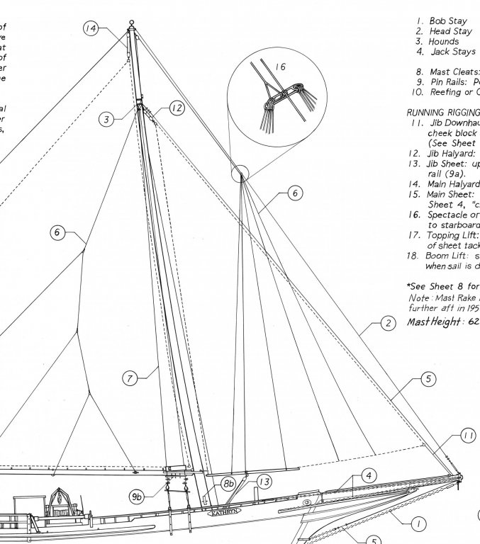


- 878 replies
-
- 22
-

-
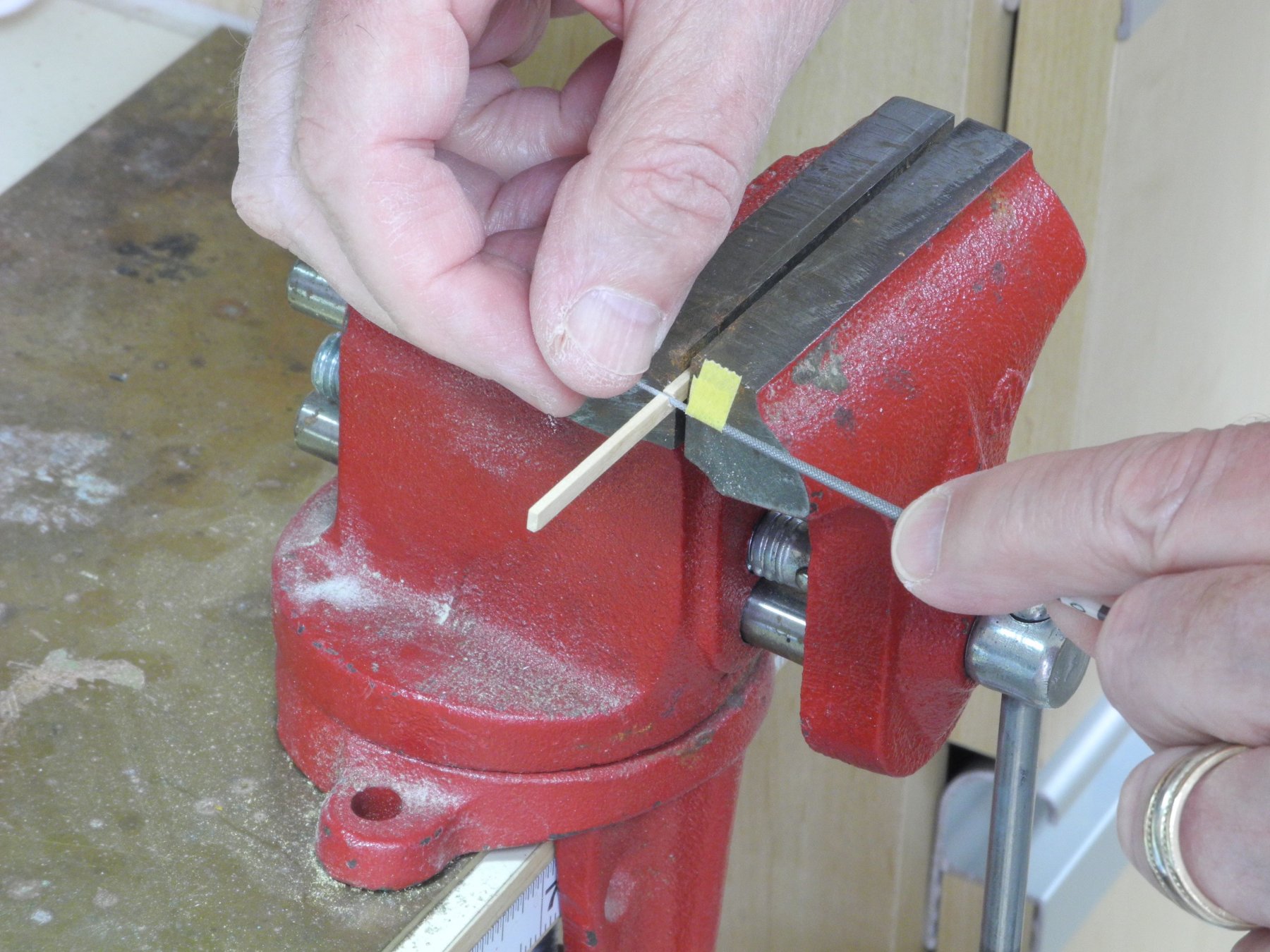
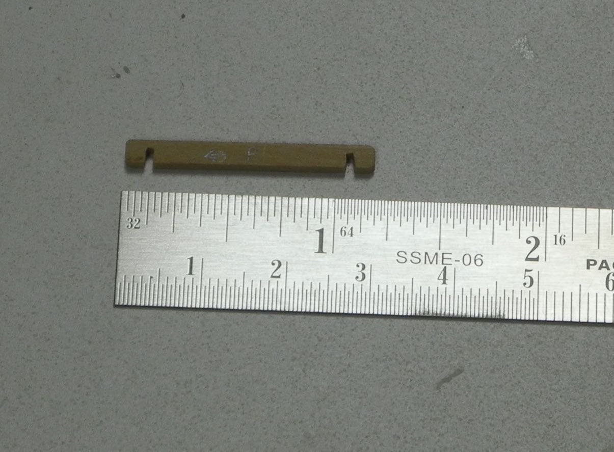
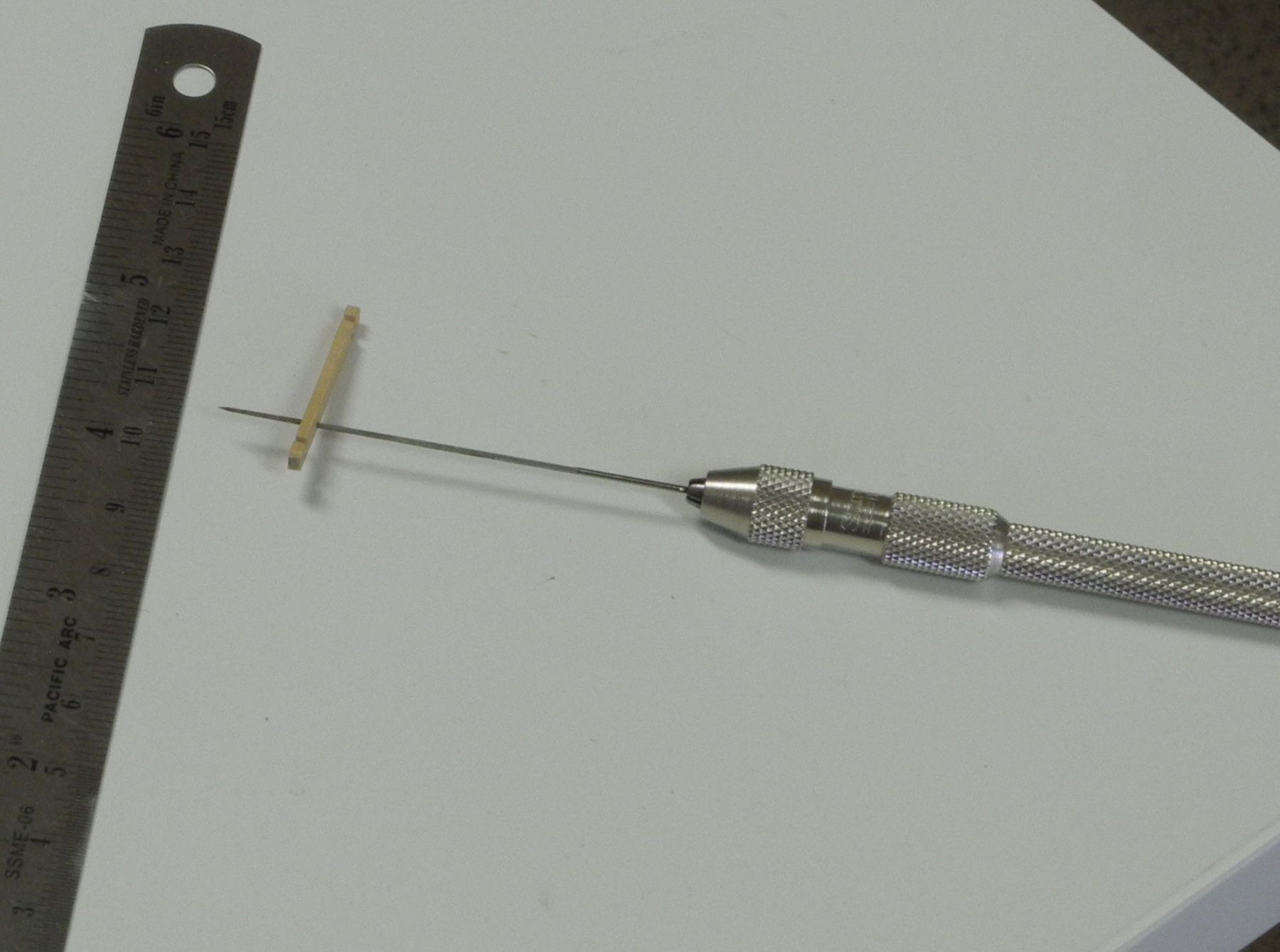
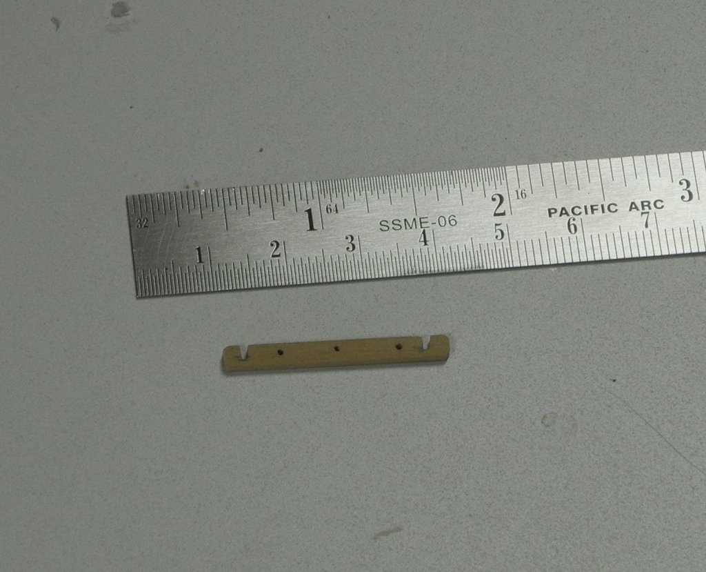
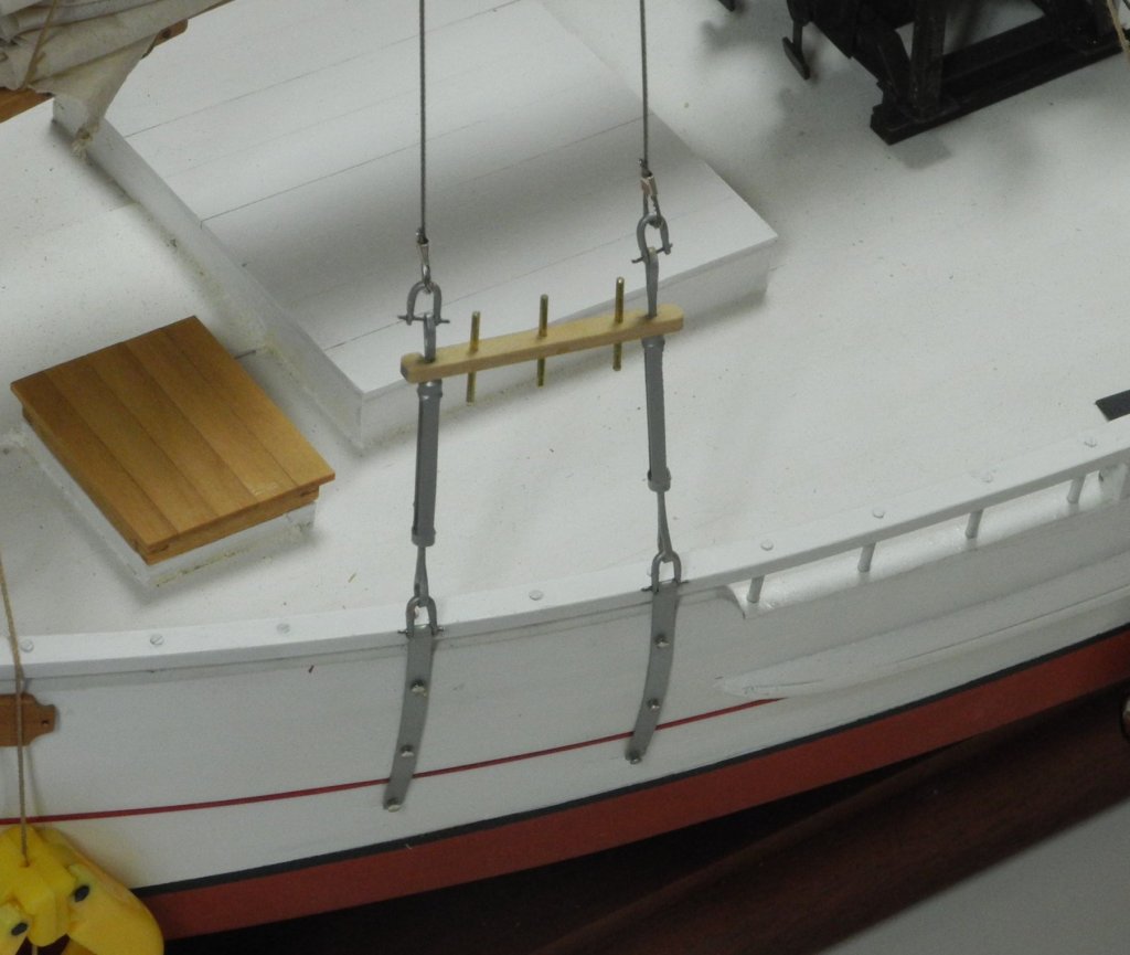
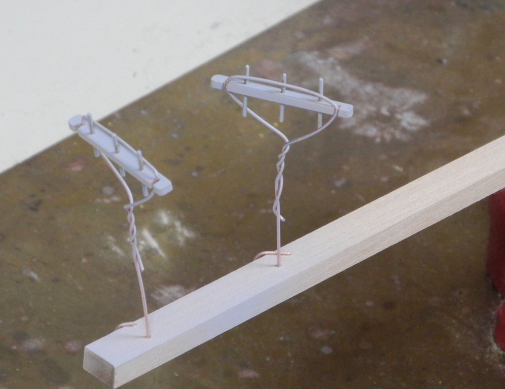
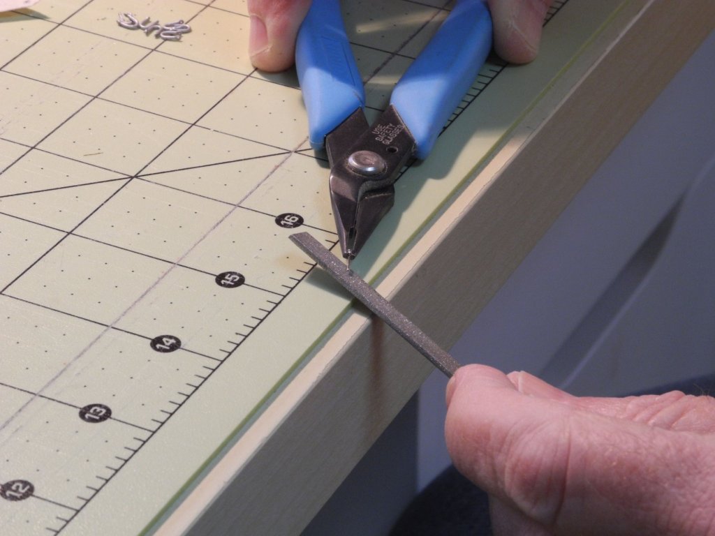
Part 91 –Pin Rails While prepping for the next rigging steps, I needed to install Kathryn’s pin rails. These are very simple – short lengths of wood attached above the shroud turnbuckles, with three iron rods in each. The wood used is a length of 1/8” x 1/16” boxwood. The first step was to make notches the appropriate distance apart, using a small round file. Since the file is tapered, the yellow tape on the file is to keep me from making the slot too large. The pin rail was then cut to size (4” outside each notch) and the corners rounded off. The holes for the three rods (1/32” brass rod) were drilled slightly tight, and then were enlarged as necessary using a very small reamer held in a pin vise. The pin rail was test fit before the rods were glued and before painting. After the rods were CA’d to the pin rail, the pin rails were painted by holding them in a jig made from wire. The following photo shows the pin rails after they were primed. The pin rails were painted using the Bare Metal paint previously used on the shroud metalwork. After painting, the pin rails were epoxied to the shroud turnbuckles. Another detail out of the way, and I’m just starting to see the light at the end of the tunnel (if I don’t think about the dredge baskets!).


- 878 replies
-
- 17
-
-
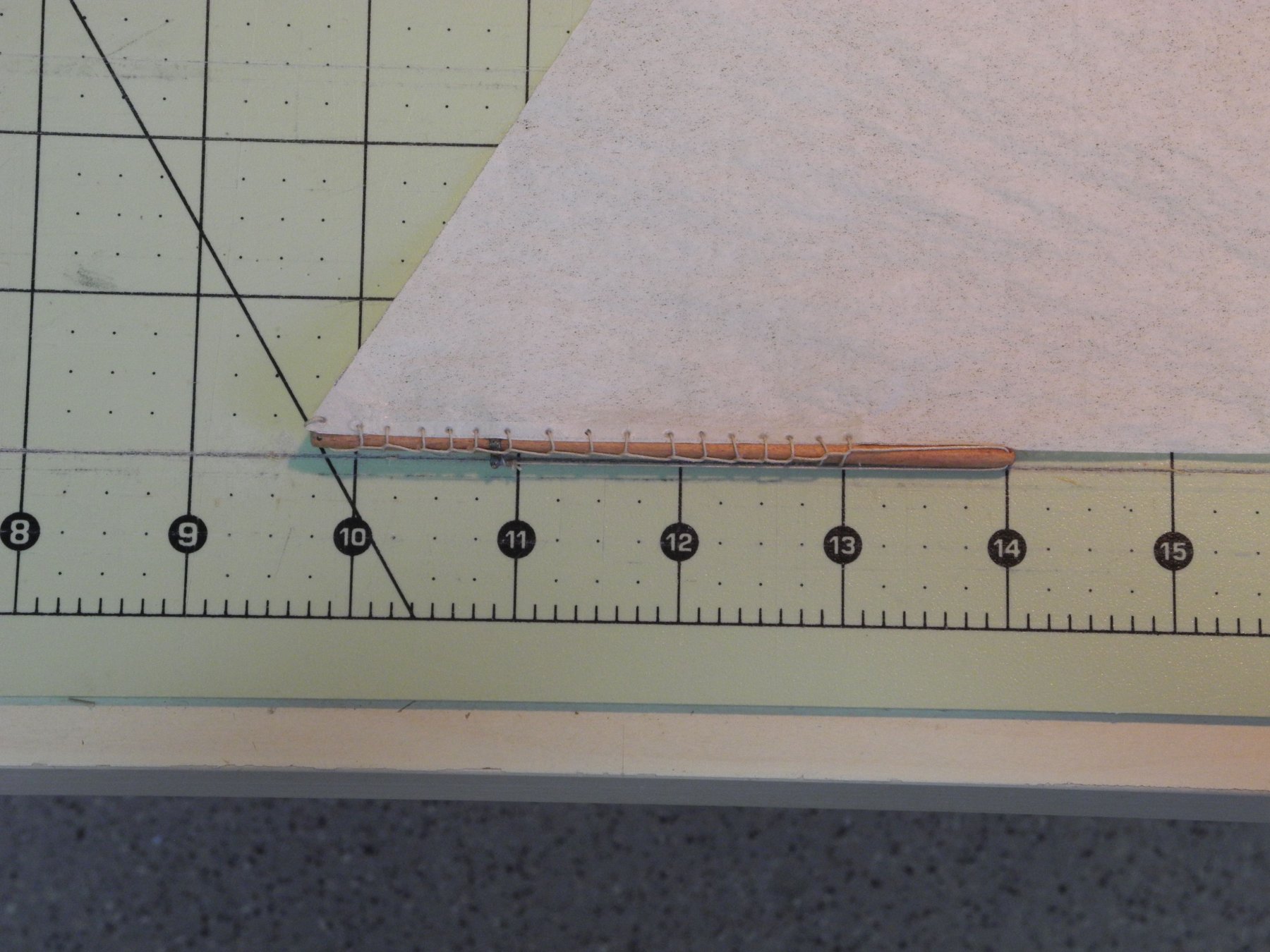
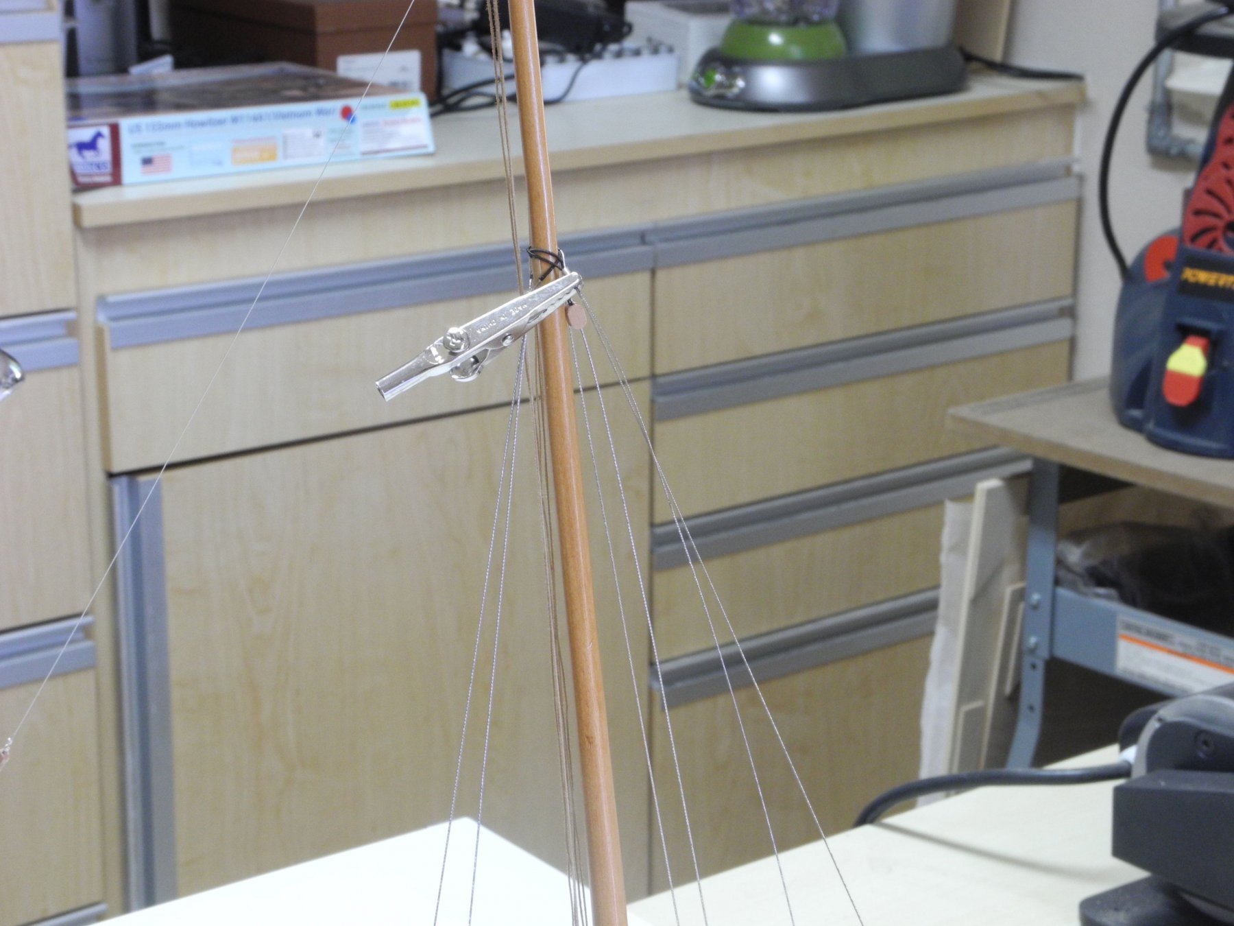
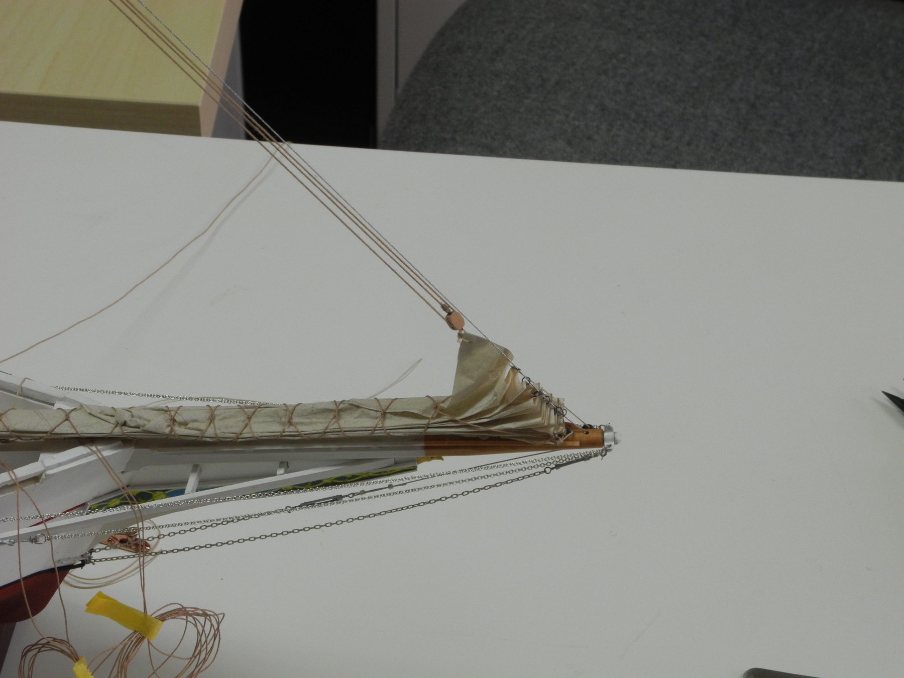
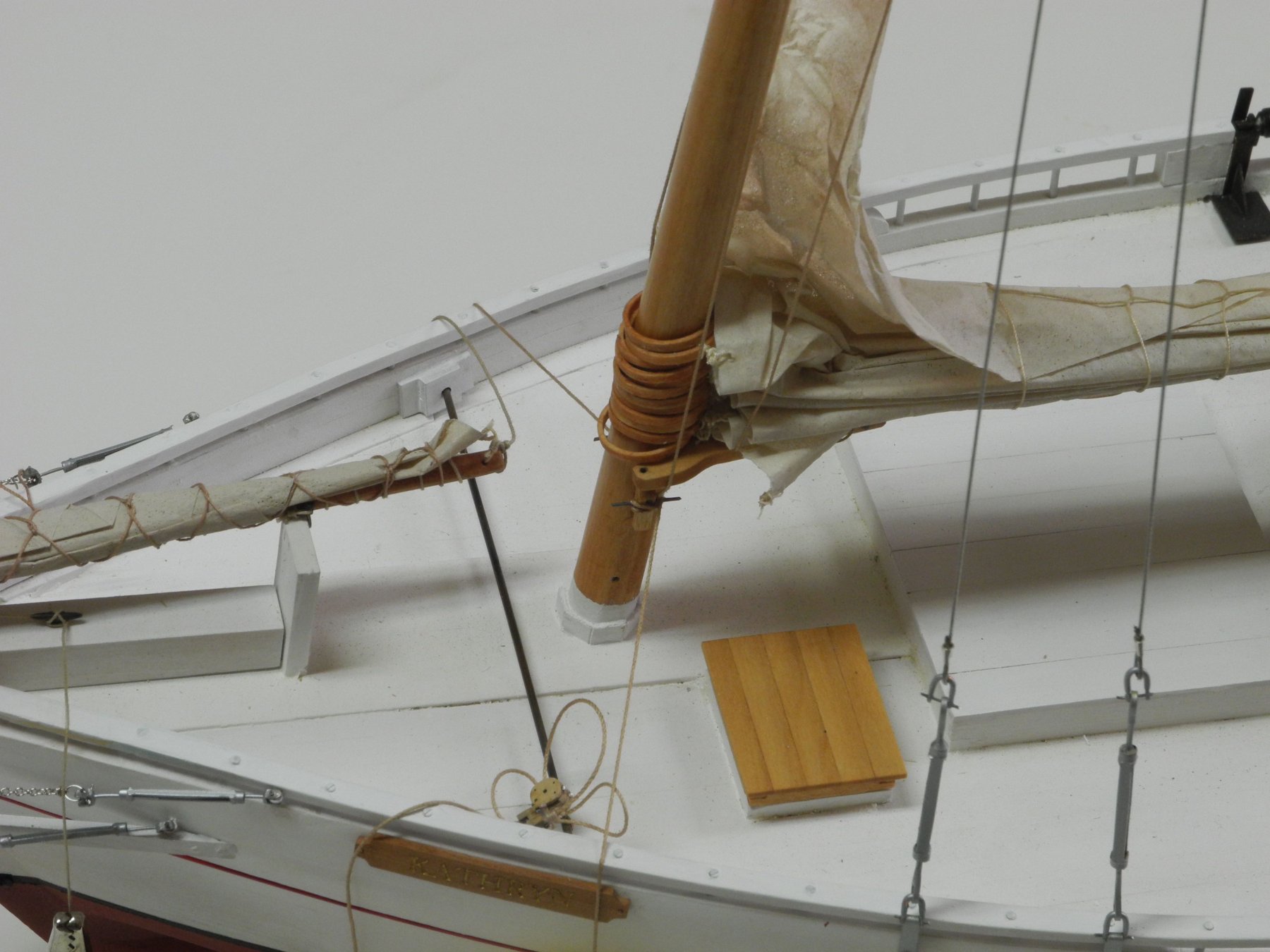
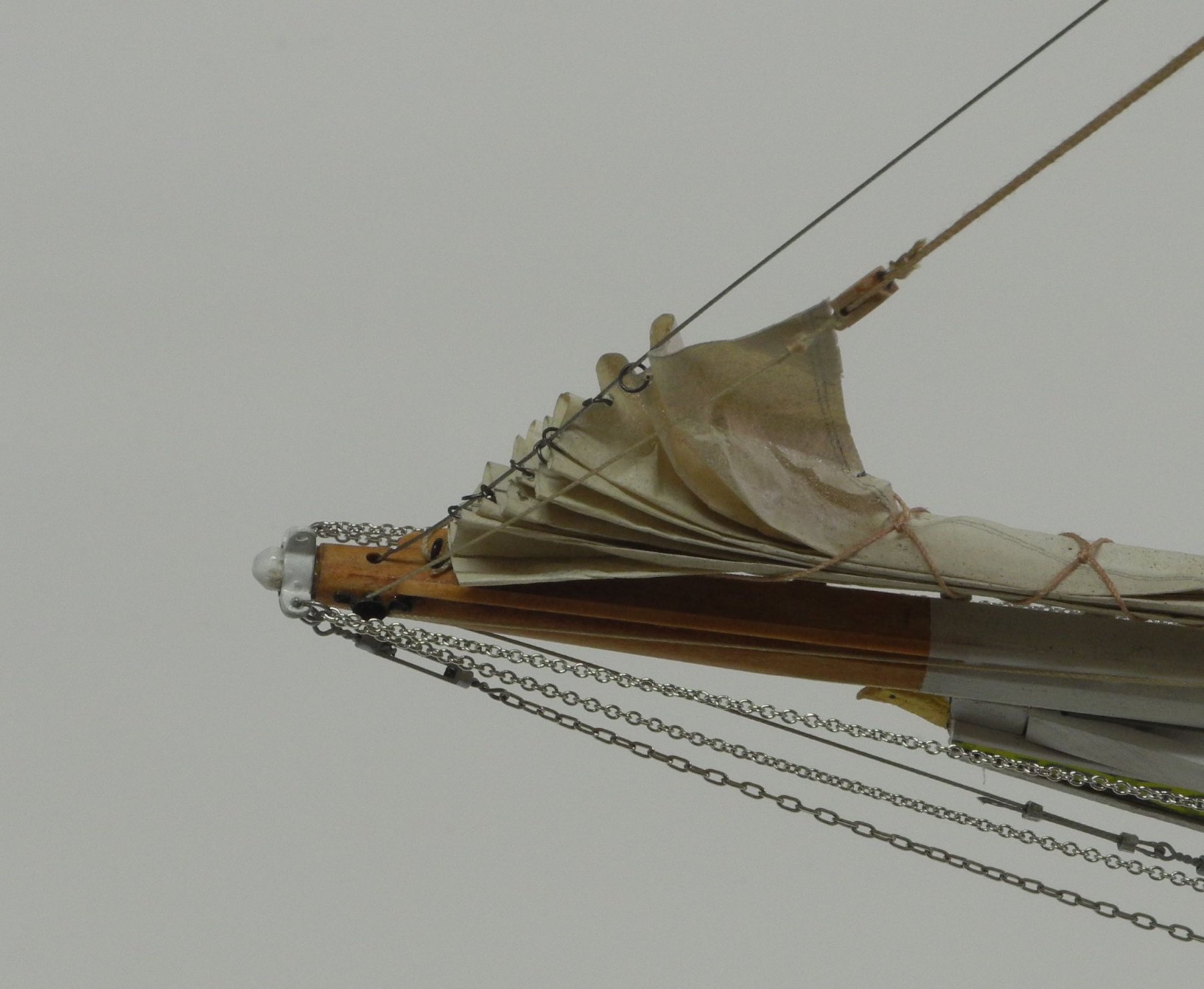
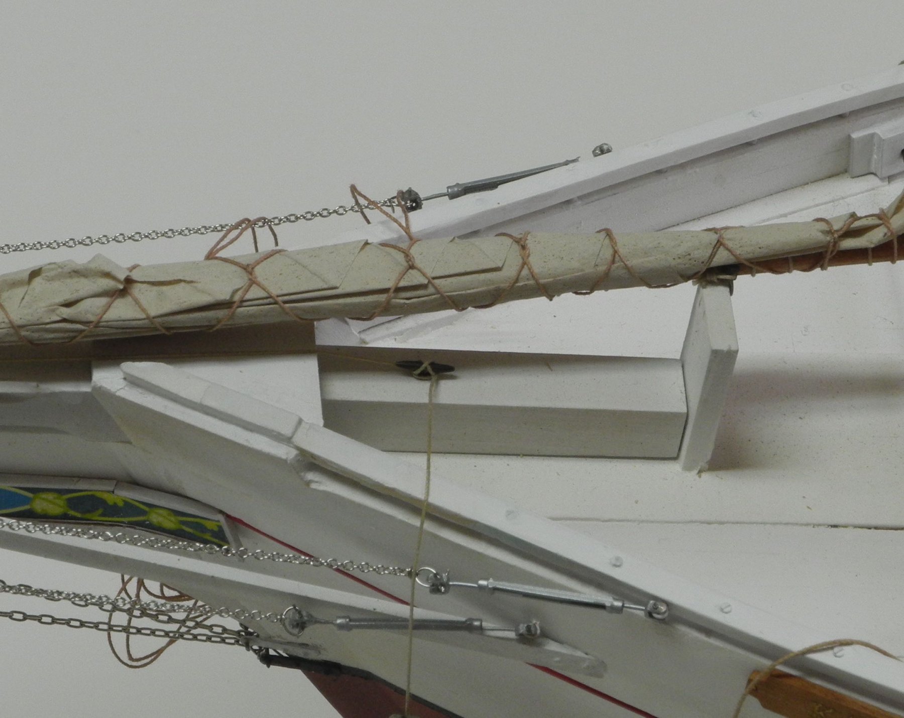
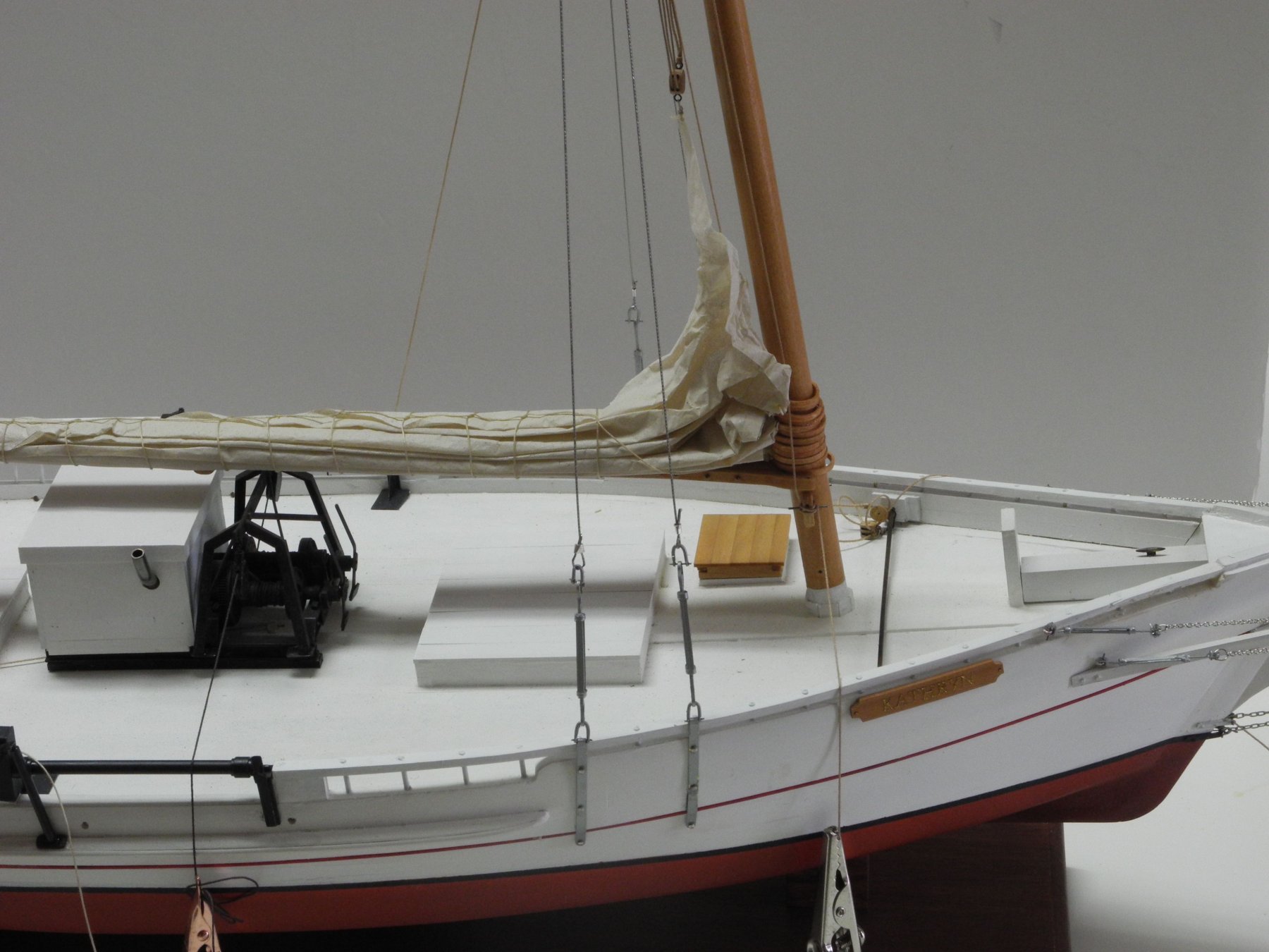
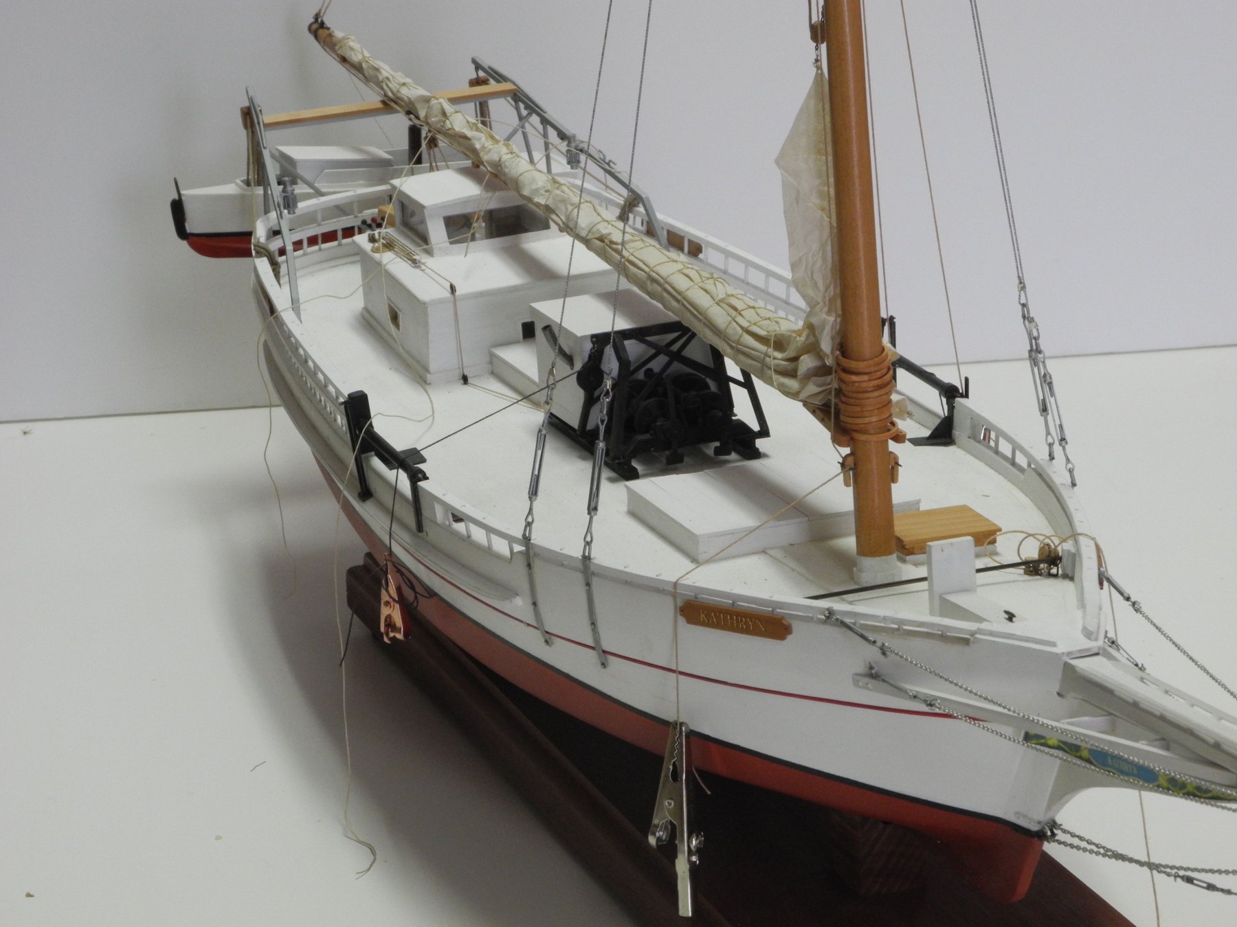
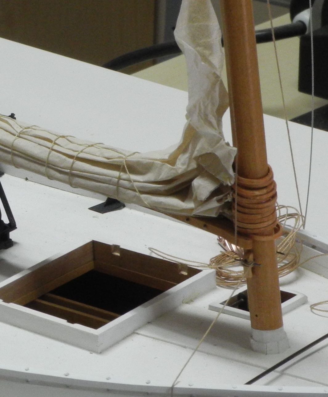
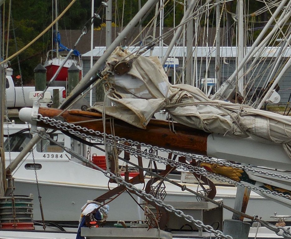
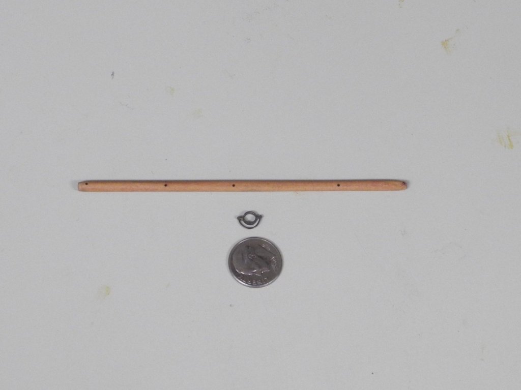
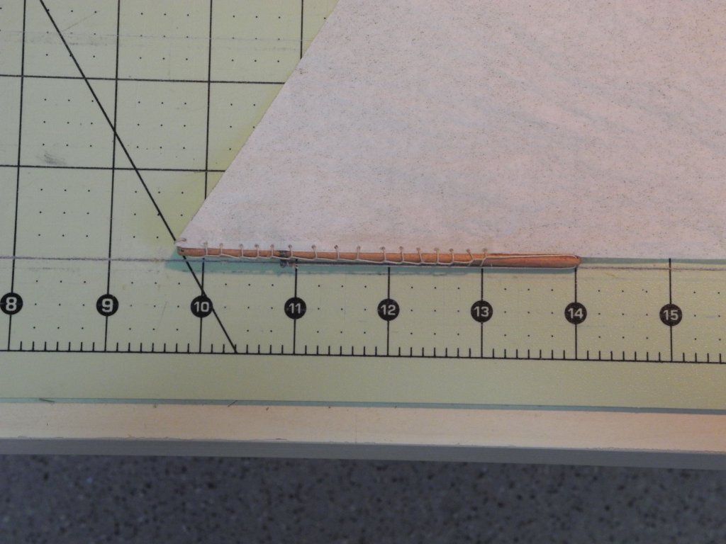
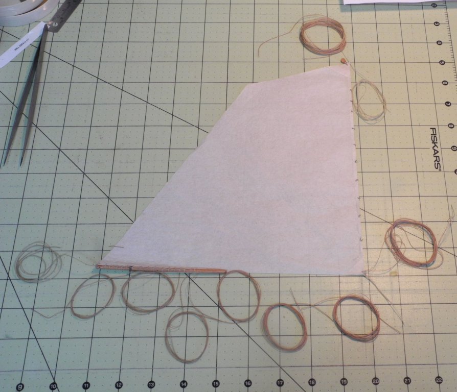
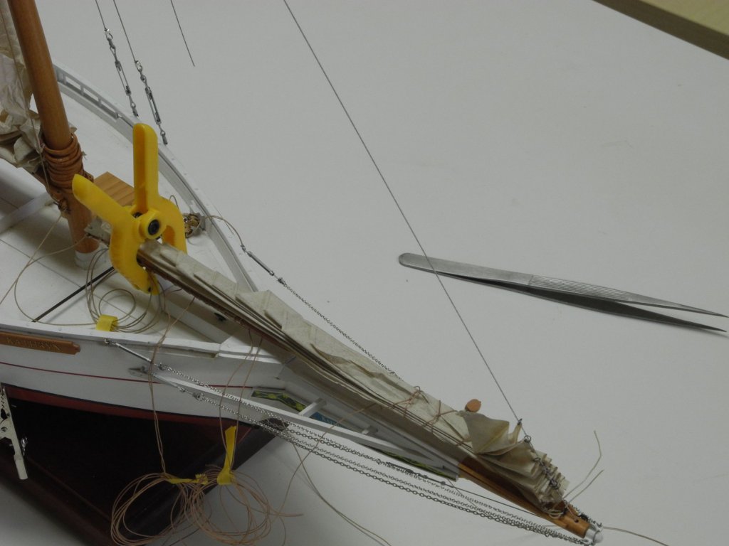
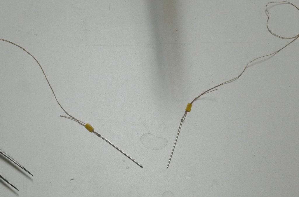
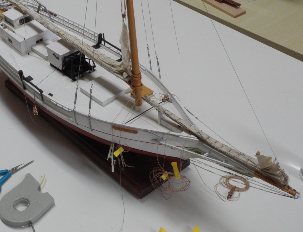
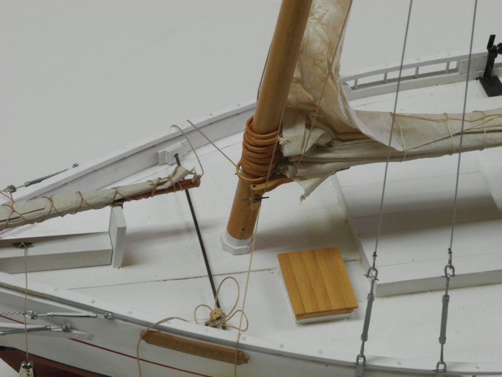
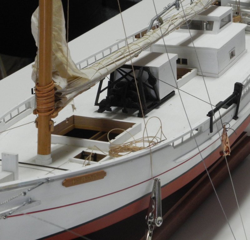
Part 90 –Jib Kathryn’s jib has a Jib Club on the aft part of the Jib, with a Club Lift tied to the aft part of the Club. There are 4 Lazy Jacks for the Jib, and the aftmost two of the Lazy Jacks run through holes in the Jib Club. The Jib Downhaul is run through a Cheek Block at the port side of the forward end of the Bowsprit. The downhaul is run from the block to the cleat on top of the bowsprit. The Jib Club was made from a piece of 1/8” square stock that was first drilled for the required holes and was then rounded and slightly tapered at each end. The bailed band for the club was made from brass stock similar to the fashioning of the bailed band for the boom. The Jib Club is laced to the Jib via a number of grommets in the aft end of the Jib. For the model, this area was reinforced with a strip of silk span to strengthen that area of the jib, and drops of white glue were placed in each spot that the holes would be made with a small awl. The lacing for the Jib Club is a little complicated, but the finished product is fairly attractive, in my view. All of the lines that would be used for the Jib and its Lazy Jacks were identified and prepared. The upper coil is the ½” Jib Halyard. Next to it is the 3/8” Jib Downhaul. At the lower end all of the lines are 3/8”, starting from the left of the photo is the Jib Club Haul; the next two coils are for the aftmost Lazy Jack which had already been run through its hole in the Jib Club; the next two coils are for the next Lazy Jack, also run through its hole in the Jib Club; the next two coils are for the remaining Lazy Jacks; and finally the last coil on the right is for wrapping the furled Jib. The Jib was furled while still off the model, and then the Fore Stay (or Jib Stay) was run through the individual rings in the Jib after it was moved to the model. The Fore Stay was temporarily secured atop the shrouds at the hounds. Since the wrapping needed to be run over and under the furled Jib, two blunt needles were used to steer the line. When the wrapping was completed it was tied off at the aft end (clew) of the Jib. The Jib Halyard was seized to the becket on top of the single block that was seized to the head of the Jib, and was run through the double block mounted just below the hounds, and finally was tied off to the port mast cleat. The Jib Downhaul was seized to the same grommet as the Jib Halyard single block, and was run through the cheek block on the port side of the Bowsprit. From the cheek block the downhaul was run to the cleat on top of the Bowsprit. I’m glad to finally put the Jib installation behind me. I’ll now review the remaining rigging items to determine what comes next.


- 878 replies
-
- 22
-
-
Hi Mark - yes I did - I wet it pretty thoroughly and was still unhappy with the result.
-
Thanks everyone for your comments on turnbuckles and taps. I think any further discussion would be better on the Modeling Tools and Workshop Equipment forum, rather than this Skipjack Kathryn build log.
-
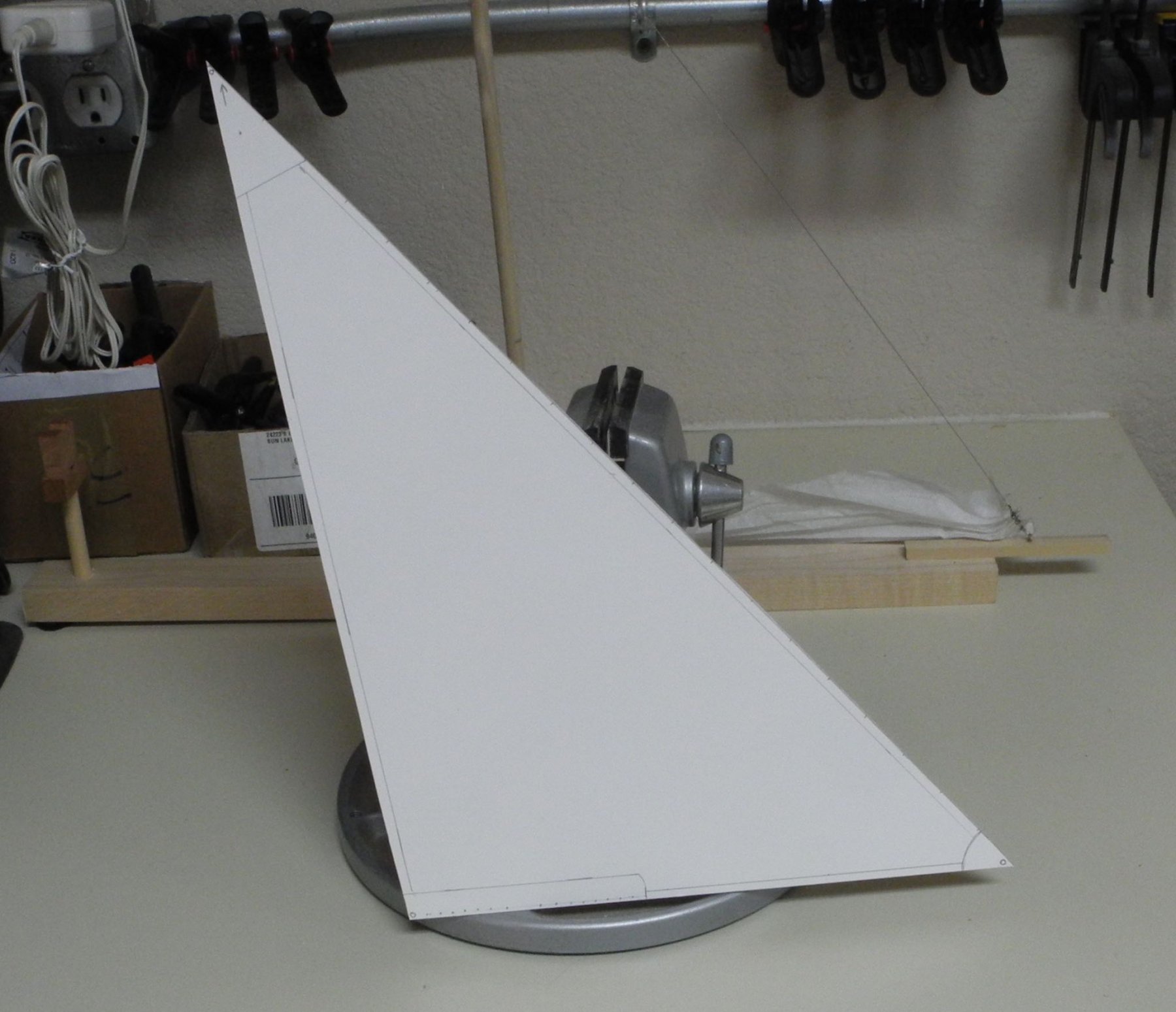
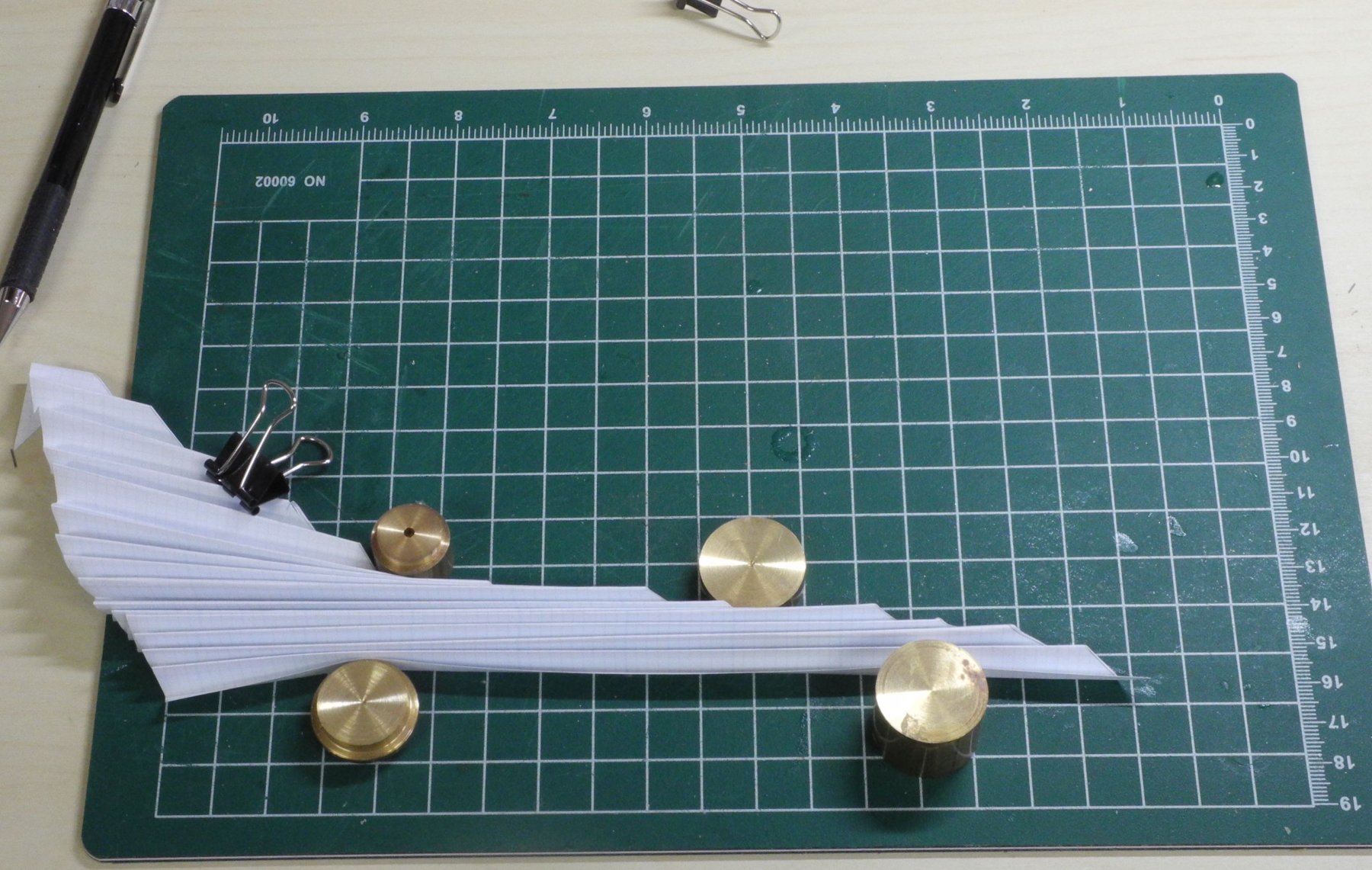
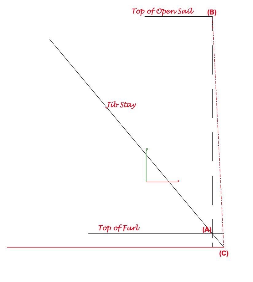
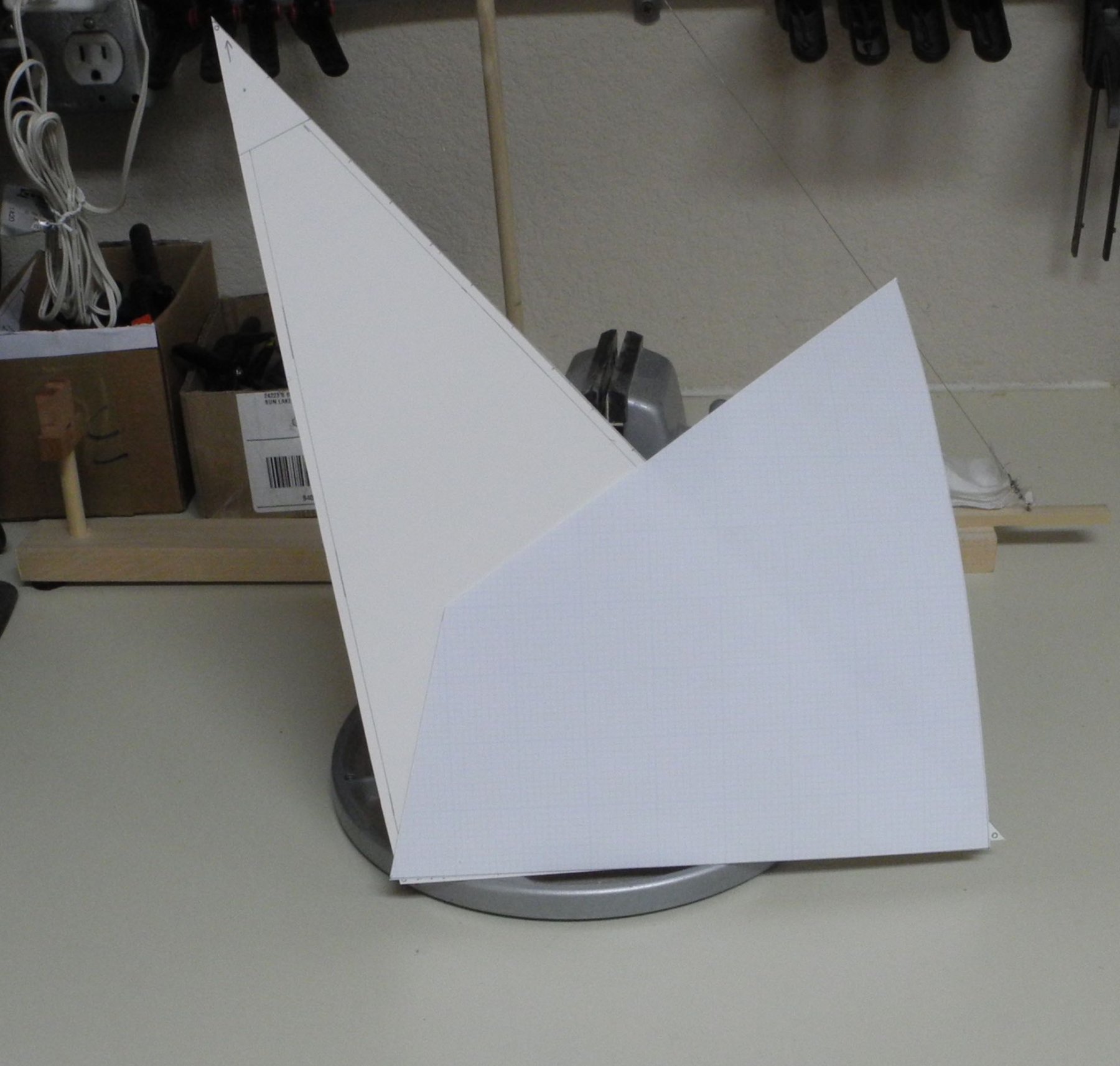
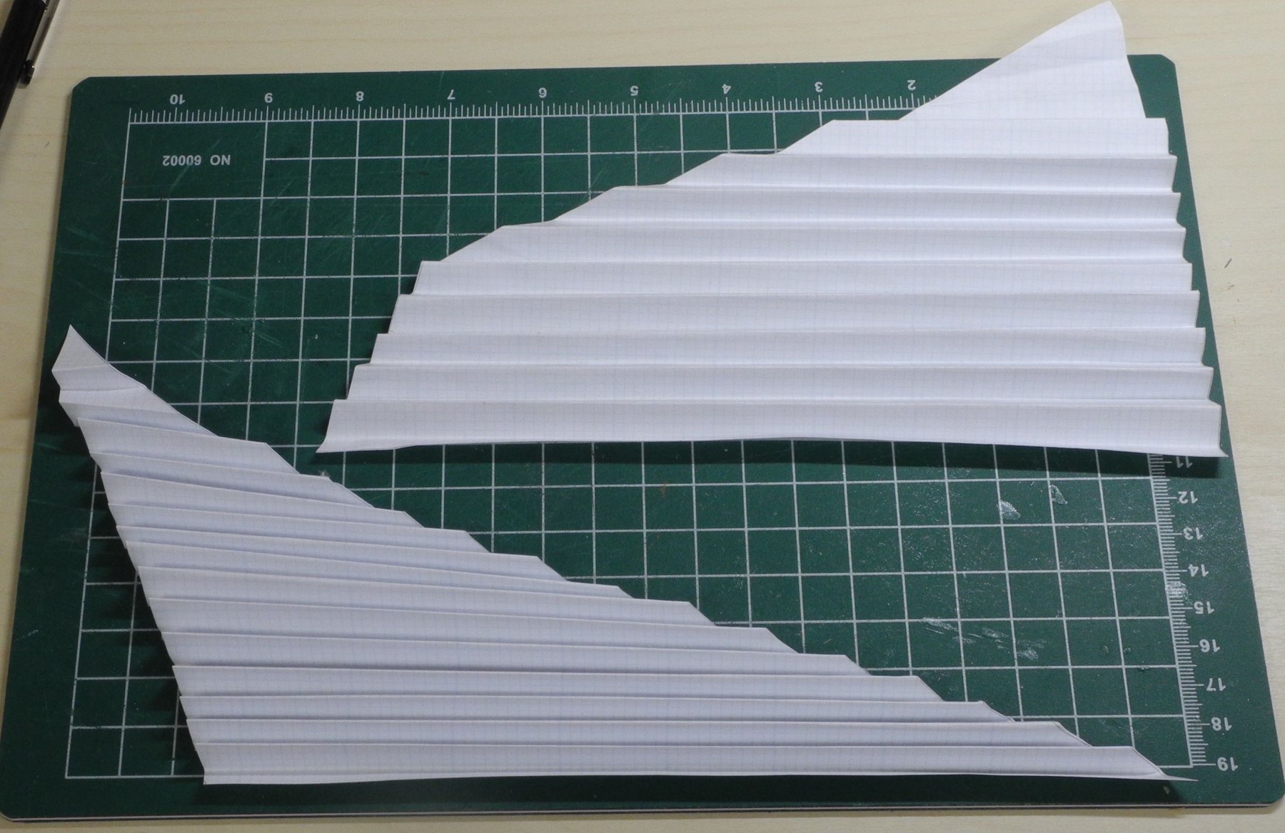
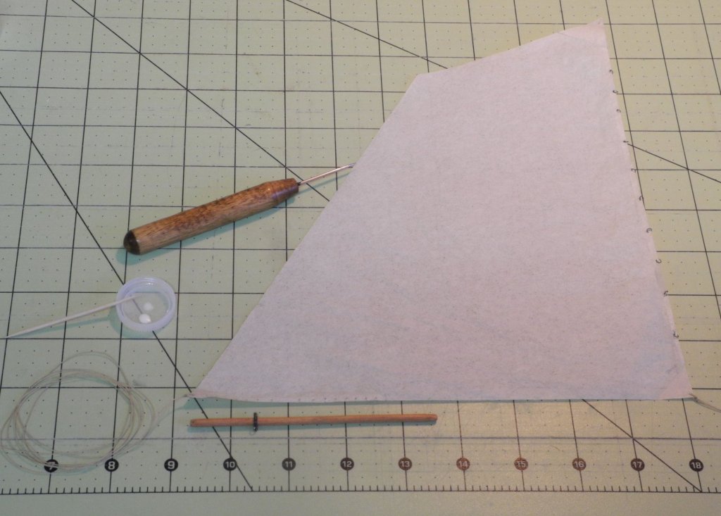
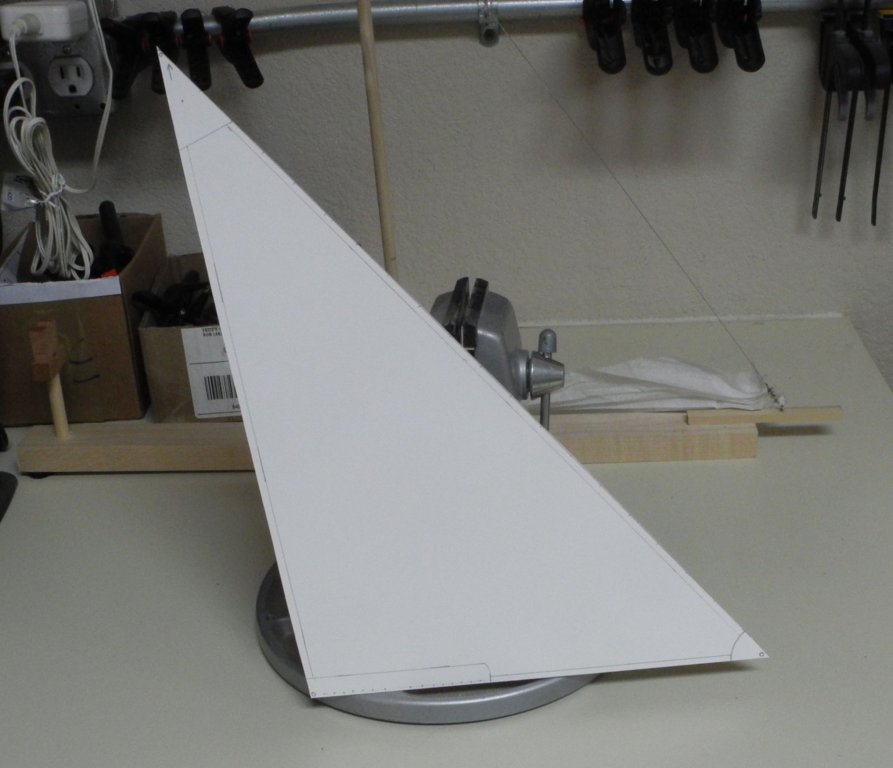
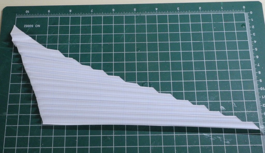
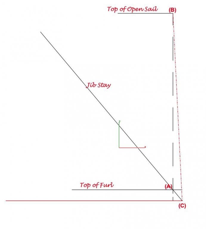
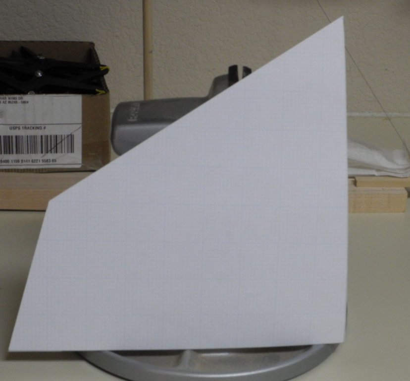
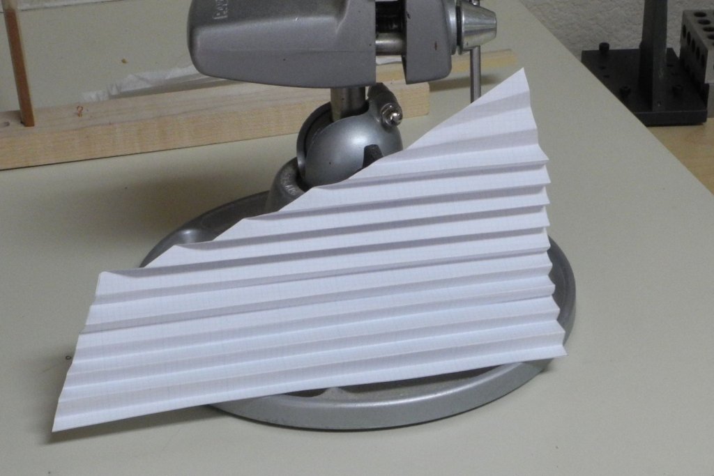
Part 89 –Jib Redesign One of the issues I’ve been facing – since before the interruption of the build last fall – was the fact that when practicing furling the jib I couldn’t prevent the jib stay from being distorted by the furled jib. So I’ve given some thought to the problem and I think I’ve come up with the answer to why this is happening, and subsequently designed an approach that I think will work on the model. To this point I’ve been working with a replica of the jib, based on the cardstock template shown in the following photo. I used some paper templates of the jib that could be folded to simulate the furling of the jib. When the jib is furled the angle of the luff, or forward edge, of the sail becomes very acute as in the following photo. Since the luff is attached to the jib stay using rings, this tends to pull the stay off its straight line and has been giving me problems in getting the furled jib to look good on the stay. I imagine this isn’t a problem on the real boat because the jib is made from fabric (vs silkspan on the model) and the jib stay can be tightened using the turnbuckle to compensate for any bending of the stay. The following photo illustrates how acute the angle can be when the jib is fully furled. The jib needed to be redesigned to allow it to be furled without pulling the jib stay out of line. I drew out some key points in designing the changes to the model’s jib. Point A illustrates the point at which the top of the furled sail will sit on the jib stay. A perpendicular line (the dashed black line) is drawn to the distance that would be the top of the open sail if it was extended forward. The end of this line is point B. Another (red) line is then drawn from the bottom of the jib stay (point C) to point B. This is the new angle of the luff on the model’s jib. Using this information, I designed a new jib for the model, as shown in the following photo. I dropped the head (top) of the sail and canted the leech (aft edge) to provide more realism to the furled jib, based on photos of Kathryn’s furled jib. The following photo shows the comparison between the two designs. The new design was folded to simulate the furled sail. Finally, a piece of silkspan cut from the new design was furled on the practice jig. It did not distort the jib stay and simulated a furled jib fairly well. Now I can proceed to making and mounting the model’s jib.


- 878 replies
-
- 14
-
-
Thanks Kurt - I'll consider that on the next model. Not sure I can make working turnbuckles - I've been working with jewelers taps and they don't come with a left-hand thread.
-
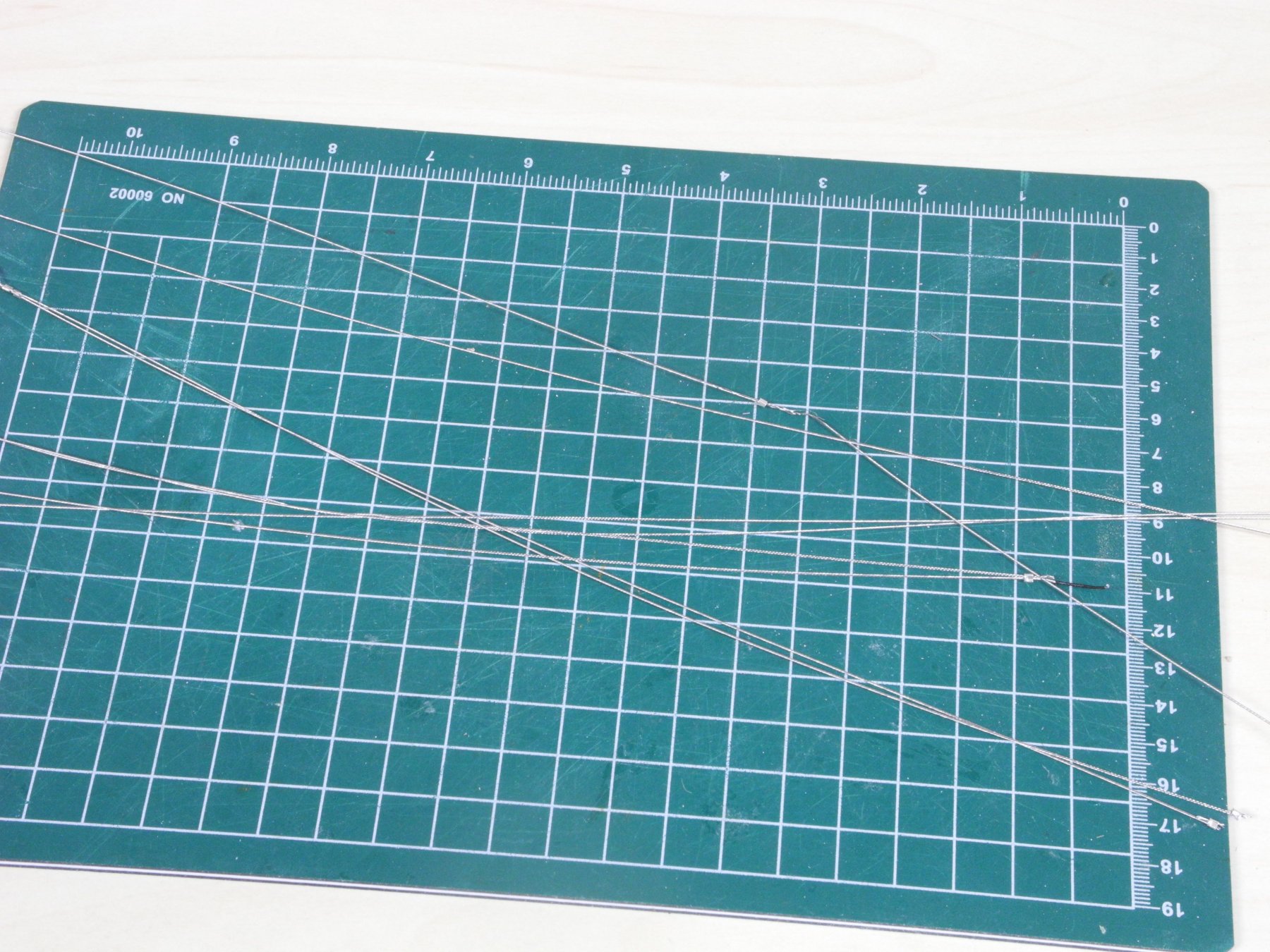
Thanks Druxey. Yes, the steel wire can be very frustrating. If I have to do this again I may look for an alternative to steel fishing line.
-
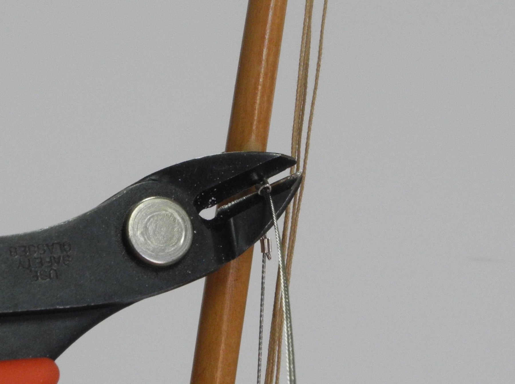
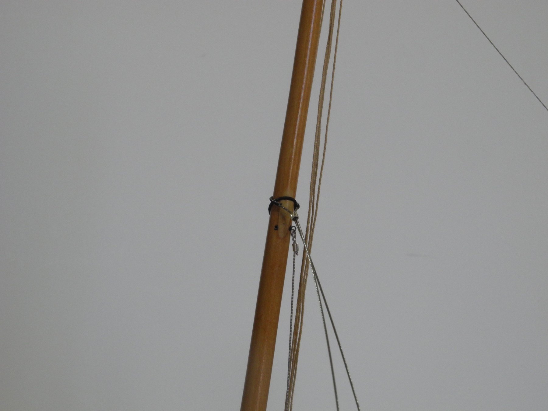
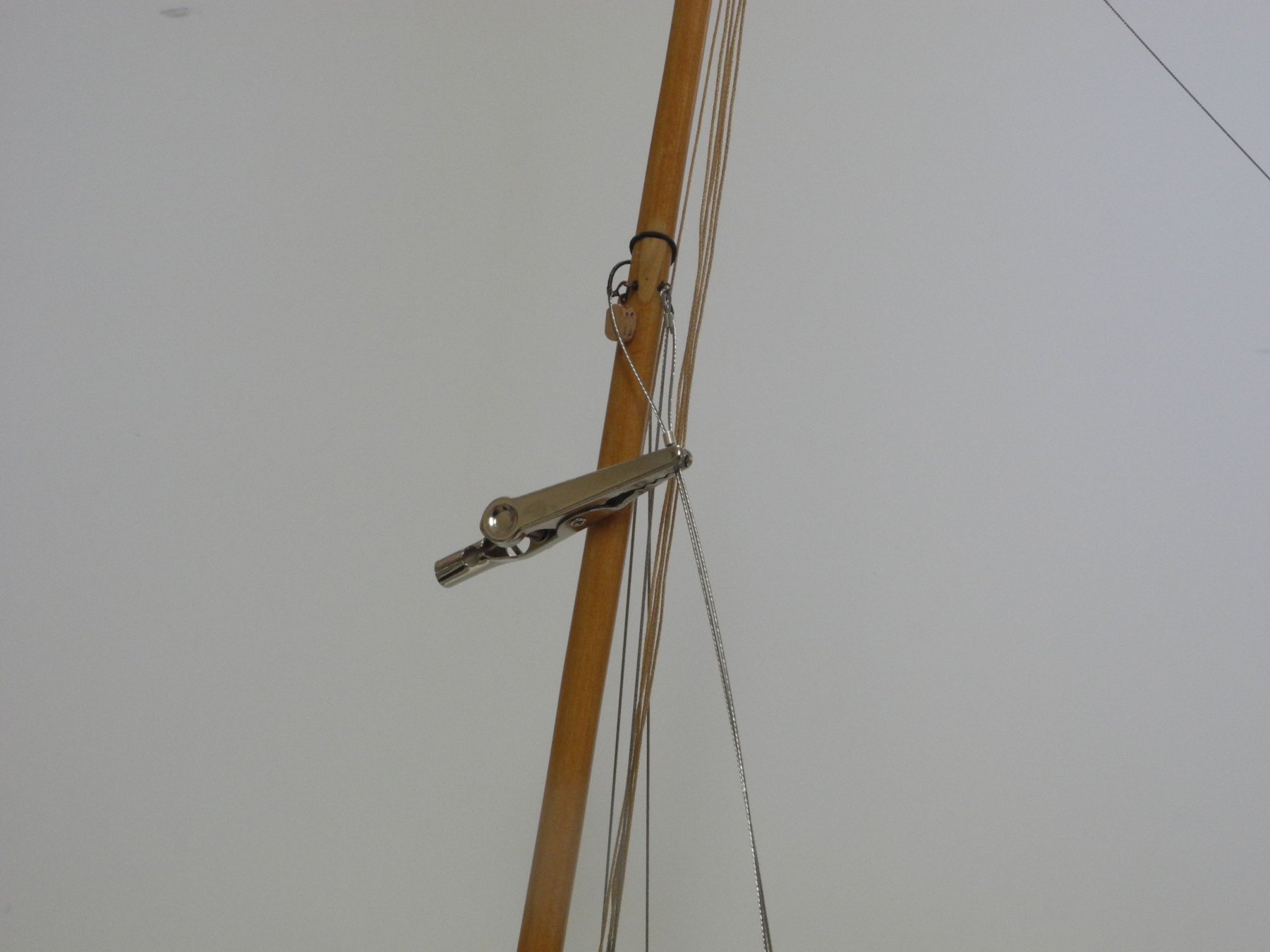
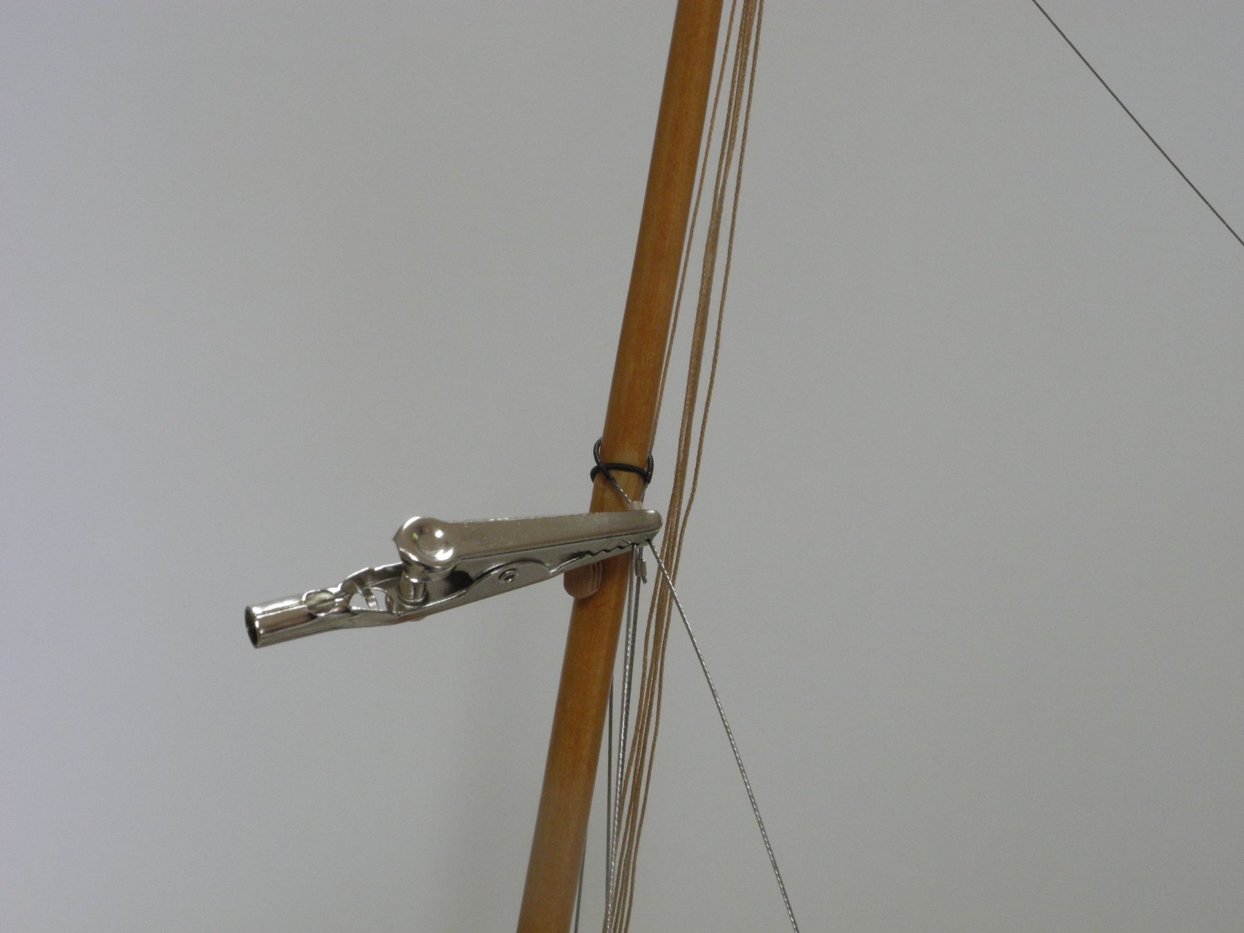
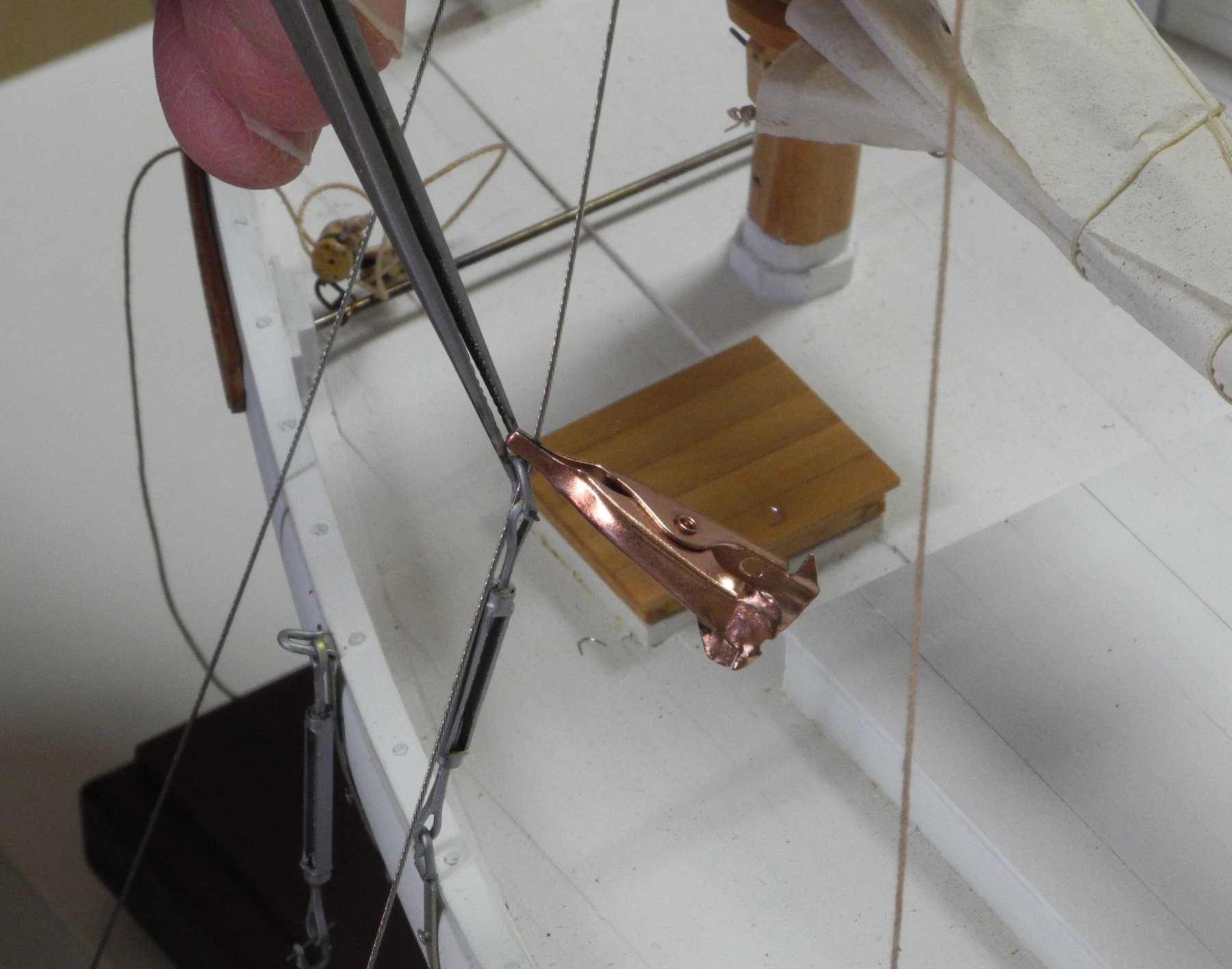
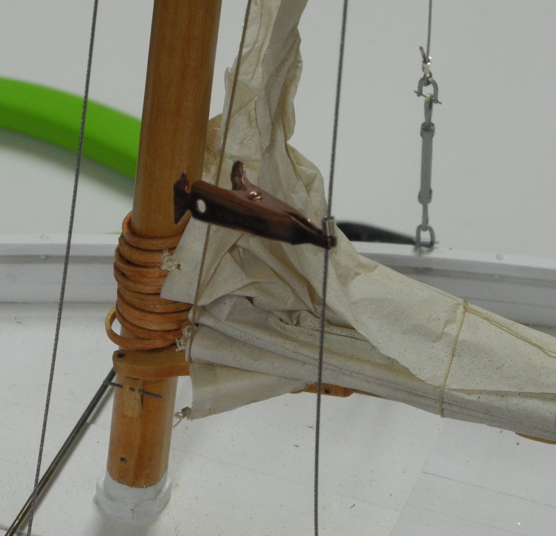
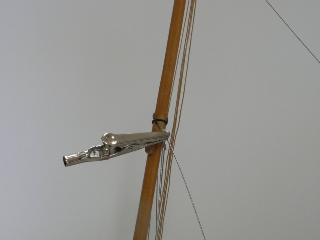
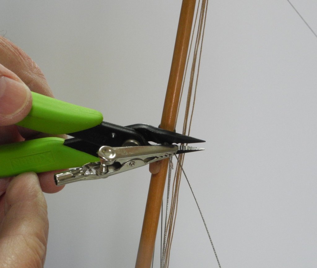
Part 88 –Shrouds cont’d After my last post I was moving Kathryn and saw that the forward port shroud moved a lot, and it proved to be too loose. Looking at it while the model was static, it looked ‘good enough’. However, we all frequently find that ‘good enough’ really isn’t good enough – so it needed to be corrected. On a model with rope shrouds, this normally means that the lanyard for the offending shroud just needs to be tightened a little more. In Kathryn’s case, however, the crimping beads couldn’t be ‘uncrimped’, so both port shrouds needed to be cut away and replaced. Since I hadn’t taken many photos of the shroud installation for the previous post I took this opportunity to record the steps. The first step was to cut away the existing shroud at the crimping beads, first at the turnbuckles and then at the hounds. The discarded shroud joined the others from the ‘trial and error’ phase. Before installing the new shroud, I decided to install the upper blocks for the jib halyard and the jib sheet, since it would be easier to do than when the shrouds were in place. The new shroud was pre-bent where it would wrap around the mast, using a mandrel marked at the appropriate diameter. The shroud was positioned at the mast hounds using an alligator clip to keep the shroud from springing open and losing the crimping bead. The alligator clip was used to push the crimping bead in place while adjusting the shroud leads, and then was used to hold the bead in place while it was crimped. The shrouds needed to be clamped to the mast at or below the hounds. The wire used for the shrouds tends to spring away from the mast, and should be held in place against the mast while installing the shrouds. After installation the spring-back would serve to tighten the shroud. The shroud was run through the shackle it would be attached to, and a small clip was used to keep track of exactly where the wire needed to be bent. After the wire was bent the crimping bead was added to the wire and a small clip was used to keep the bead from sliding off the wire, and another clip was used to keep the turnbuckle from falling off the wire. When all elements were in place the shroud was crimped at the turnbuckle. This process was then followed for the forward shroud (being left-handed, it was easier to work on the aft port shroud before the forward one). Both port shrouds are now tight and stable. Now we can start focusing on the jib.


- 878 replies
-
- 22
-
-
Hi Patrick. Looking forward to your OKTO build. Seems like you really like the radical look.
-
Thanks Carl. I'm fortunate to have loads of photographs of Kathryn, so I can study those details. That wouldn't be a fair trade, John. I remember what the paper mill added to the atmosphere during the hot weather. Thanks Druxey. Unfortunately, after my last post I discovered a problem with one of the port shrouds - I'll probably have to cut the port shrouds down and re-do them. grrrr.
-
Thanks Ed. Yes - I'm happy working in the larger scale. I'm actually thinking of 1:24 for the next model.
-
Thanks John. I just noticed you're from Mobile. I used to visit there in the 70's and early 80's when I worked for International Paper and I always enjoyed your town.
-
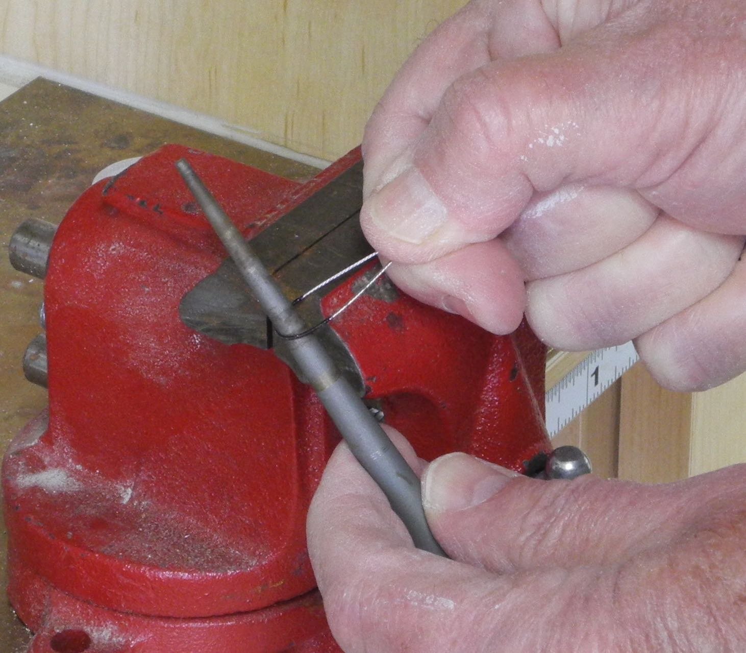
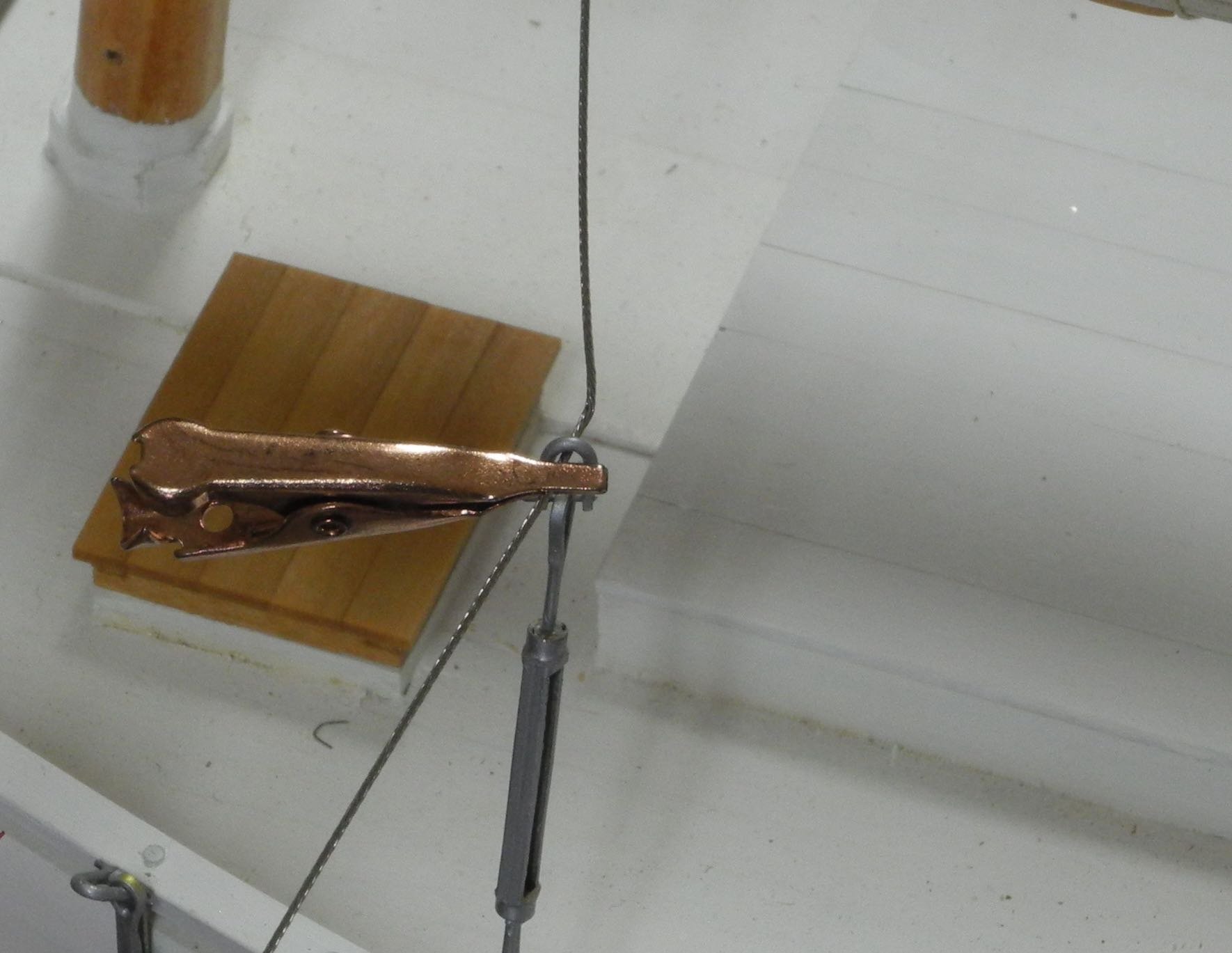
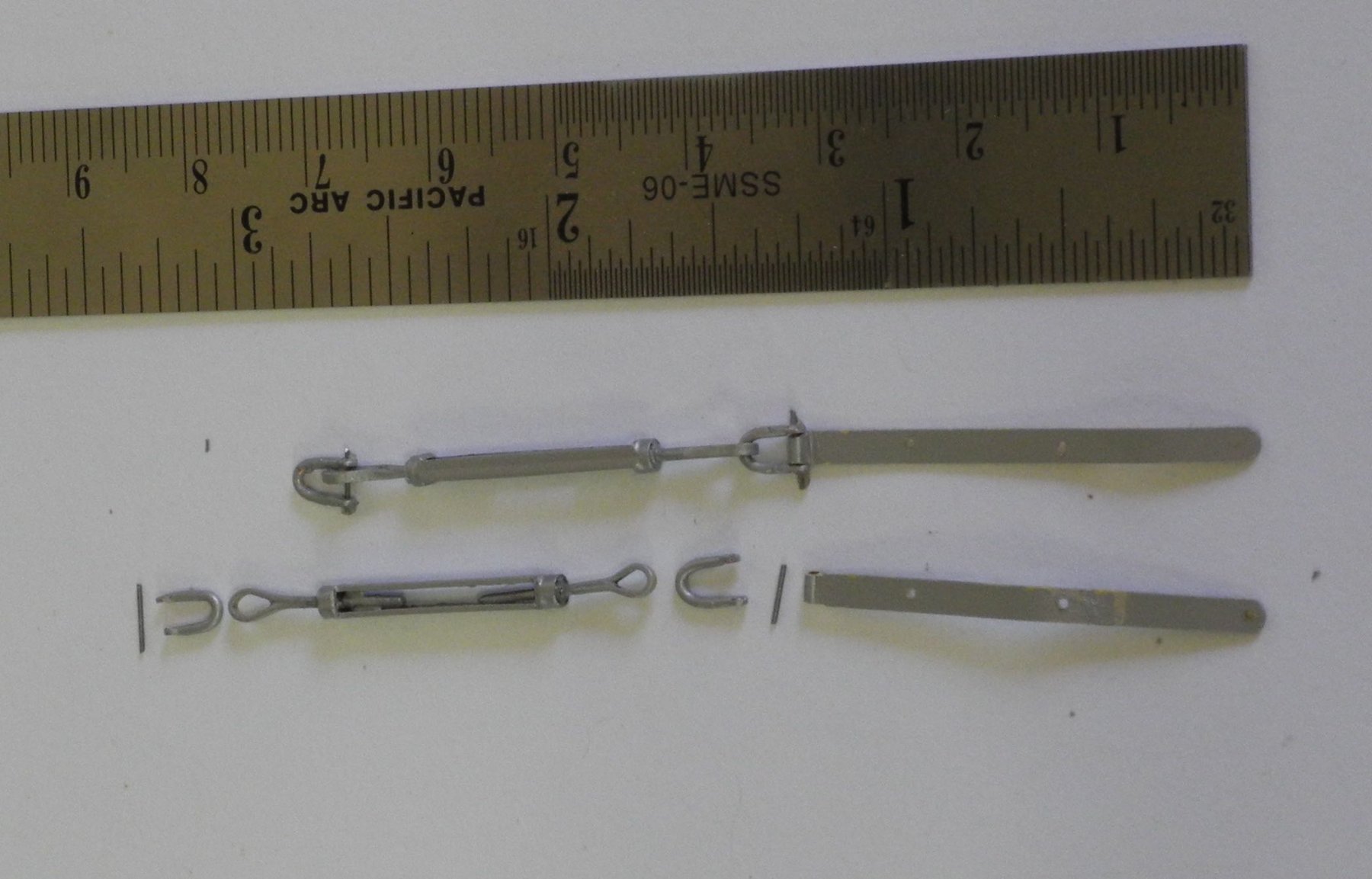
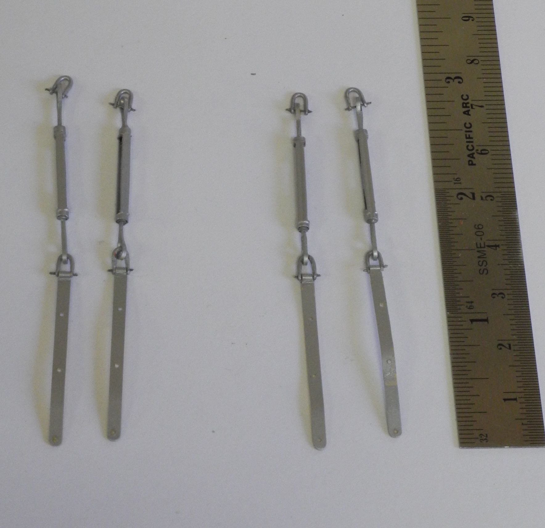
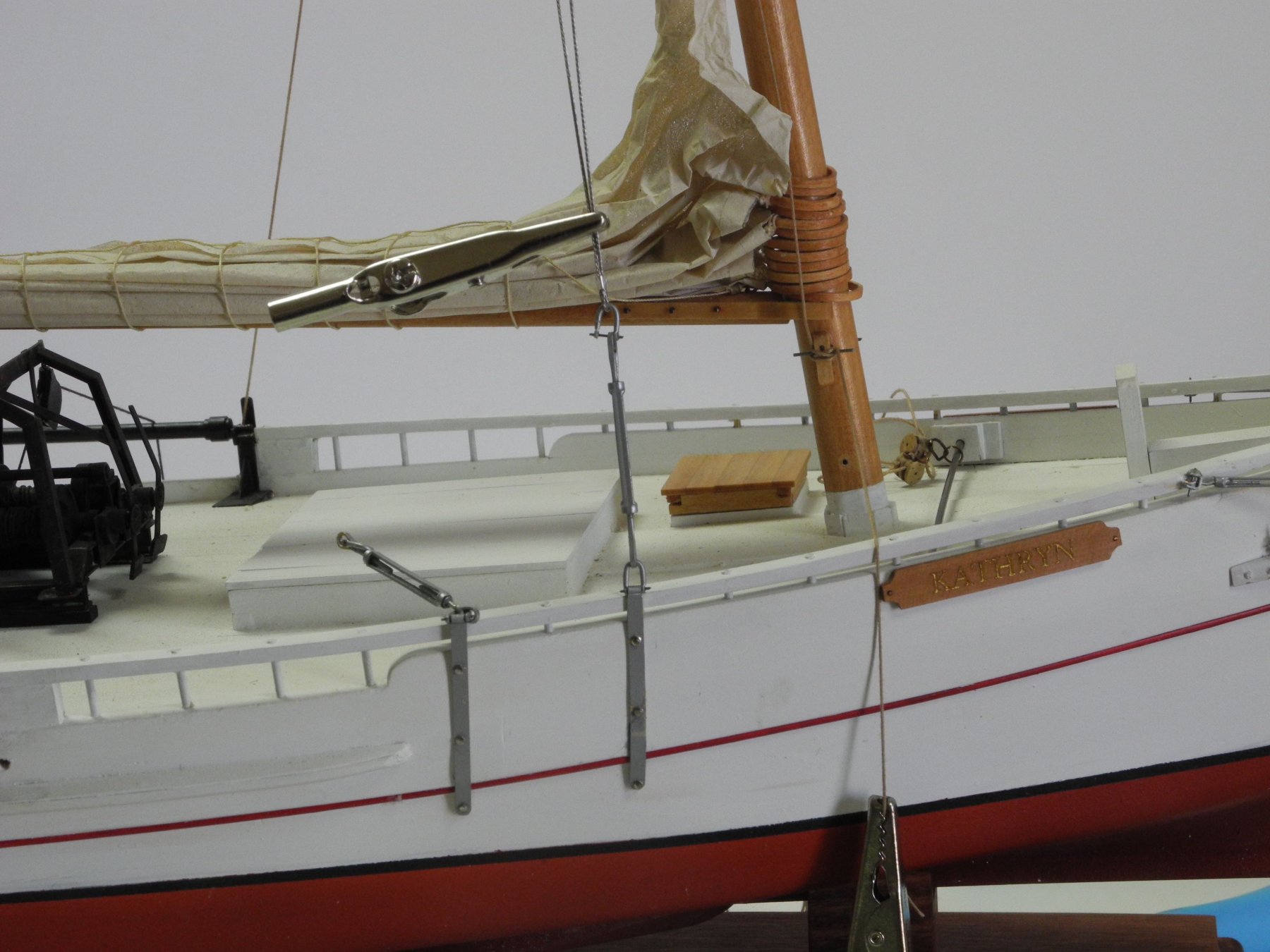
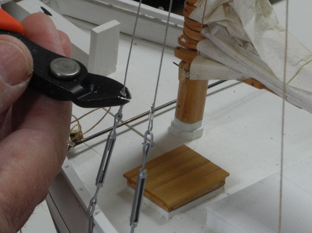
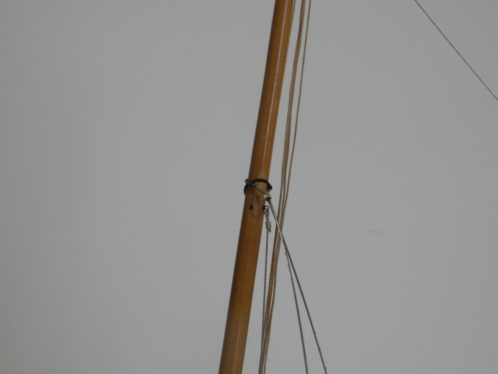
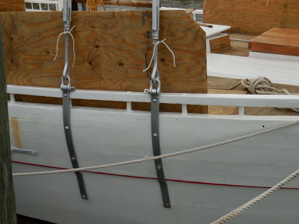
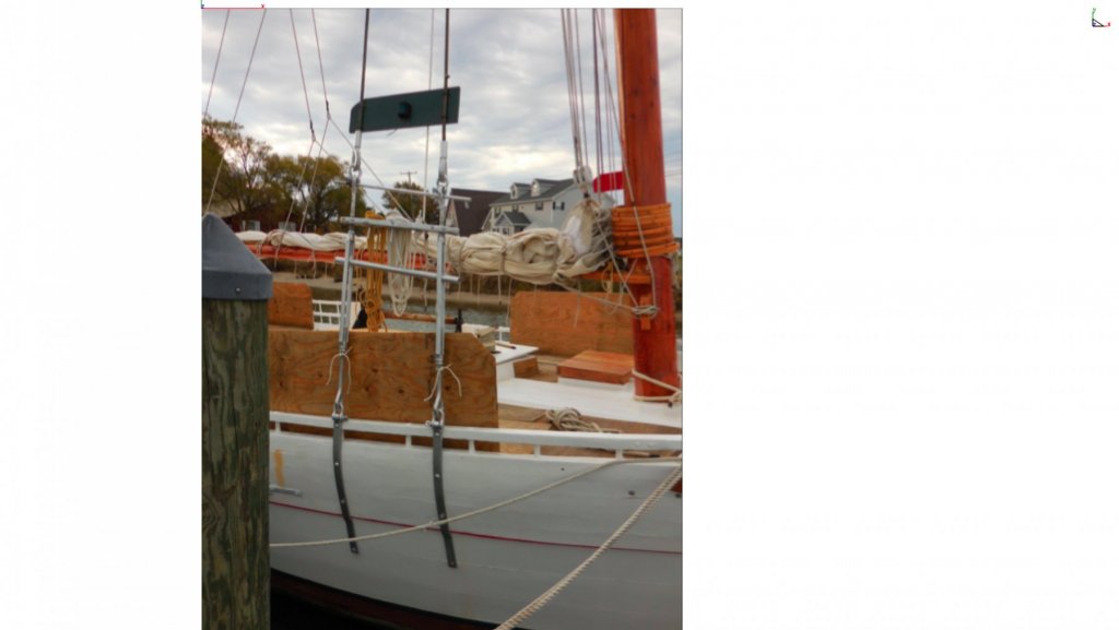
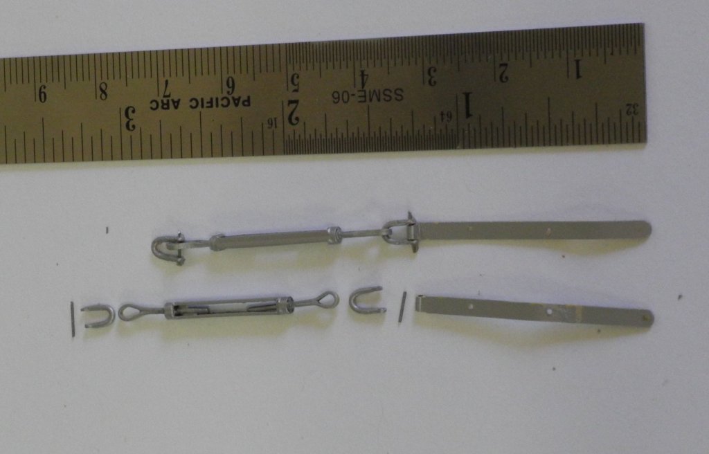
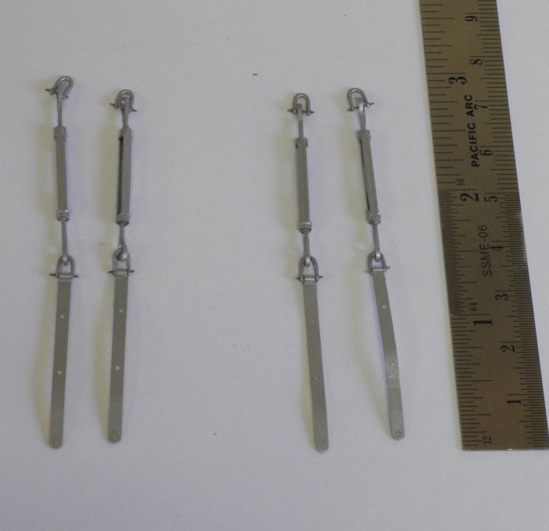
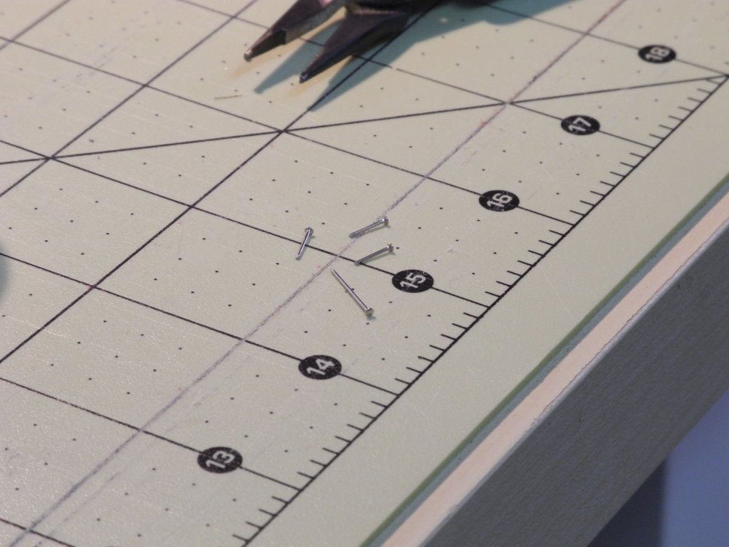
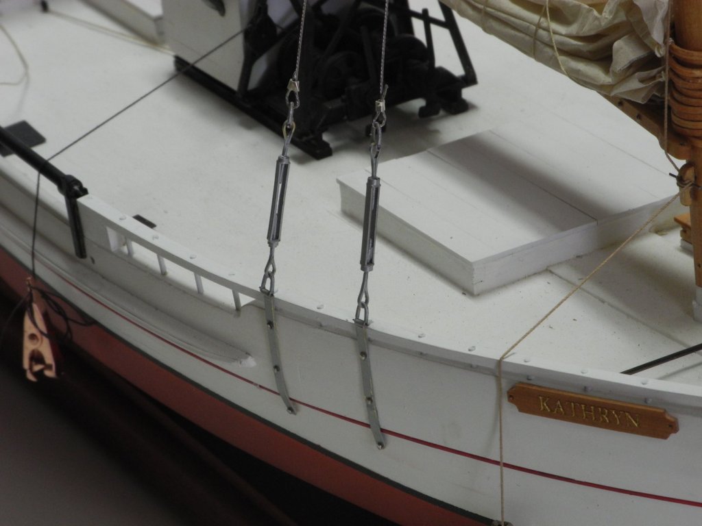
Part 87 –Shrouds My planned rigging sequence called for working on the jib next. However, since the Jib Stay needs to lay on top of the shrouds at the mast hounds, it quickly became obvious that the shrouds needed to be fully installed before this could reasonably be done. So, installation of the shrouds became the next step. Kathryn’s shrouds are connected to two chainplates on each side. These chainplates are connected to large turnbuckles via shackles, and then shackles are used to attaché the shrouds to the turnbuckles. All of this hardware was prepared in Part 75 (last July!!). Now it needed to be assembled and installed on the model. The shrouds had been loosely installed in Part 85 but it was very obvious that the port shroud was too loose and should be re-installed. Since the shrouds are made of wire they could not easily be removed and re-used once the crimping beads were in place. This meant that the shroud needed to be cut loose and another shroud made in its place. Because there were a lot of questions in my mind about the best way to proceed, I decided to install all of the chainplates/turnbuckle hardware, and to then focus on installing the shrouds on the starboard side. Assembling the hardware began with attaching the lower shackle to the turnbuckle, and then pinning the shackle to the chainplate. The chainplate was held fast in a small vise, and then a piece of .014” piano wire was used as the pin. Piano wire was the choice for the pin because of the amount of stress that would be put on that joint during the installation of the shroud. A small drop of CA glue was placed on the piano wire outside of the shackle on each side of the shackle before trimming the ends of the pin. This would keep the small pin in place. The glue was applied with a small needle held in a pin vise. The following photo shows an assembled chainplate/turnbuckle assembly, along with the six individual pieces of the assembly. Once the four assemblies had been completed, it was time to mount the chainplates to the hull. The chainplates needed to be pinned to the hull to accommodate the stress of installing the wire shrouds. Small pins measuring .020” thick and .5 long were used as the mounting bolts. These were trimmed to a shorter length and then the cut end was smoothed with a small diamond file. The long pin in the first of these photos is a full-sized pin that had not yet been cut down. The pliers used to hold the pins while filing are specifically made for holding, pushing, and pulling small nails. This allowed me to move the pin back and forth on the file, rather than trying to file such a small area. The bolt holes in the chainplates had already been pre-drilled using a #74 drill. The chainplate was held in the appropriate position, and a pilot hole was made on the hull using the small pin shown above. The holes were drilled in the hull, and then the bolts, after dipping in medium viscosity CA, were used to mount the chainplate assemblies to the hull. To install a shroud, an alligator clip was used to push a crimping bead down on the shroud to the final position. The alligator clip then held the crimping bead in place while it was crimped using a crimping tool. This is where the problems started. After installing the two starboard shrouds it was obvious that the aft shroud was too loose. These wire shrouds can’t be installed by simply pulling them taut as could be done with rope. A different method needed to be developed to get them tight. After a lot of trial and error (and several shrouds being thrown away) I found a couple of key steps were needed: First, the shrouds needed to be clamped to the mast at or below the hounds. The wire used for the shrouds tends to spring away from the mast, and should be held in place against the mast while installing the shrouds. After installation the spring-back would serve to tighten the shroud. Also, the shroud would loosen while trying to crimp it around the shackle at the turnbuckle. To avoid this loosening, I measured the shroud length against the shackle, and made a sharp bend in the shroud at the point where I wanted it to turn. Until I worked out these points I was seriously considering simulating the steel cable by dying some rope to a light grey color and then using gloss medium to give it a sheen. I apologize for not taking any photos while installing the shrouds – I guess I was too intent on the installation. The following photos show the completed shrouds. I think I can now get back to working on the jib – hopefully that will be the subject of the next post.

- 878 replies
-
- 26
-
-
Thanks Kurt and Gary for the kind comments. March has been a really busy month and I haven't been able to get any work done on Kathryn. This is the time of year when friends and family like to visit Arizona to get the chill out of their bones. I'm hoping to get back to work this week and to finally make some more progress on Kathryn.
-
Absolutely beautiful Ed. It must feel good to be on the home stretch after 5+ years.
- 3,618 replies
-
- 6
-
-
- young america
- clipper
- (and 1 more)
-
Hi Ron Yeah, the Willie Bennett rigging plan has been really valuable. I've used it in conjunction with a lot of the photos I have of Kathryn to help me understand some of the details. I made a conscious decision on the Boom Lift to make a more practical tackle rather than what either plans show.
-
Thanks Popeye - I’ve left the rigging a little loose, but I’ll be tightening the rigging as work progresses.
-
Hi Mark. Sorry, I can't answer that question - I had the same question when it came to running the halyard down to the cleat. I checked my photos of Kathryn and it looks like I've rigged it correctly. Looking ahead, the same question will probably come up when rigging the Jib Sheet - it ends at the port cleat on the mast.
- 878 replies
-
- 10
-
-
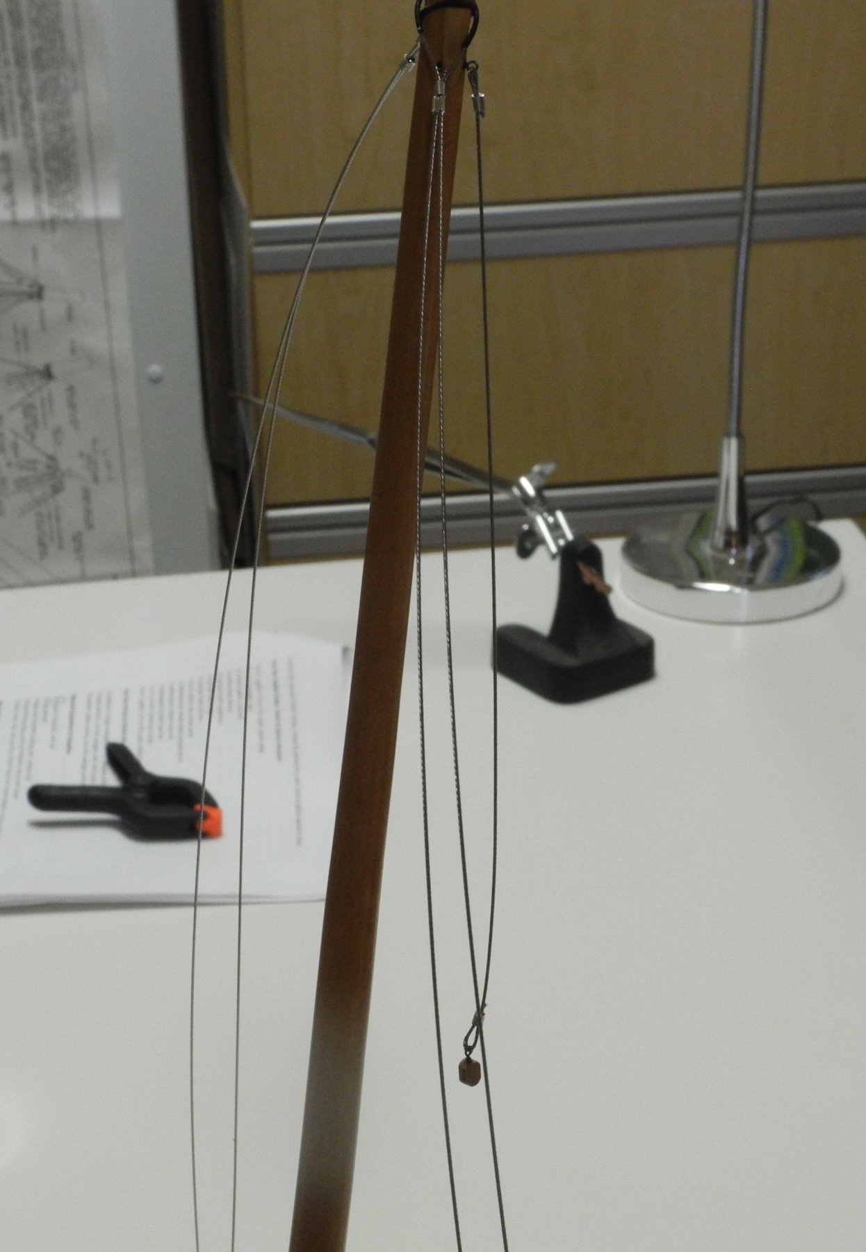
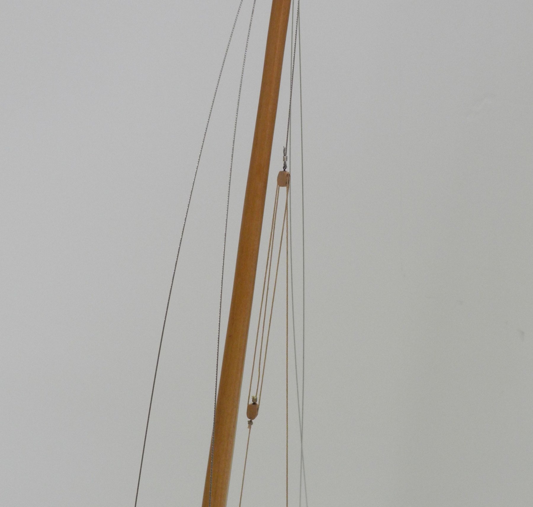
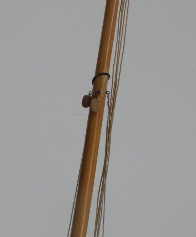
Part 86 –Boom Lift and Main Halyard Time in the shop has been hard to find of late – lots of chores that need to be done. In trying to plan out the Boom Lift and the Main Halyard, I found a good article on the tackles that are typically found on ships, and I heartily recommend it for those modelers (like me) that have questions about rigging the various blocks used on ships: http://www.tpub.com/steelworker2/59.htm The Main Halyard is actually a fairly simple arrangement. A triple block is supported by a ringbolt set into the Main Mast just below the Masthead Band. A double block with a two beckets is attached to the head of the Mainsail via the lower becket. The Main Halyard is seized to the upper becket of this block and is then reeved through the triple and double blocks. The Main Halyard is then tied off to the starboard mast cleat. The upper part of the Boom Lift is comprised of a wire Boom Lift Pendant that is hung from an eyebolt set into the mast just below the hounds. On the drawings, this pendant terminates in a single block through which the Boom Lift is reeved. I started by setting up the Boom Lift in this manner After reading the article cited above, however, I felt that this would only provide a mechanical advantage of one. Since this would make lifting the boom a very difficult task I decided to deviate from the drawings and to use a tackle comprised of a double and a single block. This yields a mechanical advantage of three, and separates the Boom Lift into two segments. A double block was seized to the Boom Lift Pendant. The lower segment of the Boom Lift is seized to the lower becket of a single block. The upper segment of the Boom Lift is seized to the upper becket of the same block, and is then reeved through the double and single blocks and terminated at the pin rail of the port shrouds. Since the shrouds will not be completed until a later date, the boom lift was weighted by an alligator clip and was left suspended over the port side. The next post will address the preparations for installing Kathryn’s jib. Thanks everyone!


- 878 replies
-
- 22
-
-
Binker by Omega1234 - FINISHED
Mahuna replied to Omega1234's topic in - Build logs for subjects built 1901 - Present Day
Very nice, Patrick! I wish I could have seen this build in progress.