Mahuna
-
Posts
1,504 -
Joined
-
Last visited
Content Type
Profiles
Forums
Gallery
Events
Everything posted by Mahuna
-
 Thanks John. Just got back from my trip and will get back to work in the next day or so.
 -
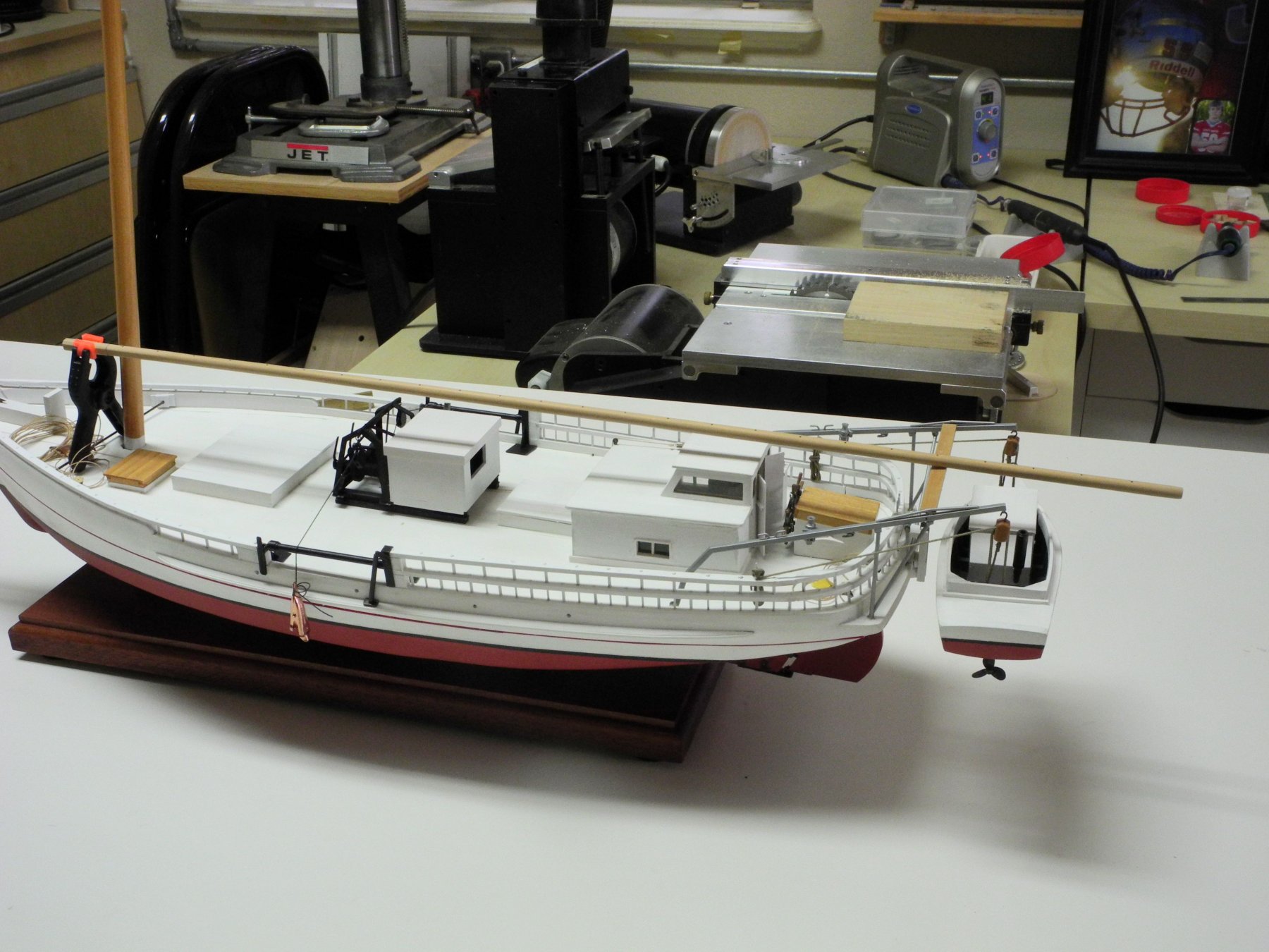
Thanks, Mark. Yes, the boom seems thin, but that's how it measures out from the HAER drawings and how it appears in photos. I should have mentioned that Kathryn's boom is laminated - that may contribute to its strength and size.
-
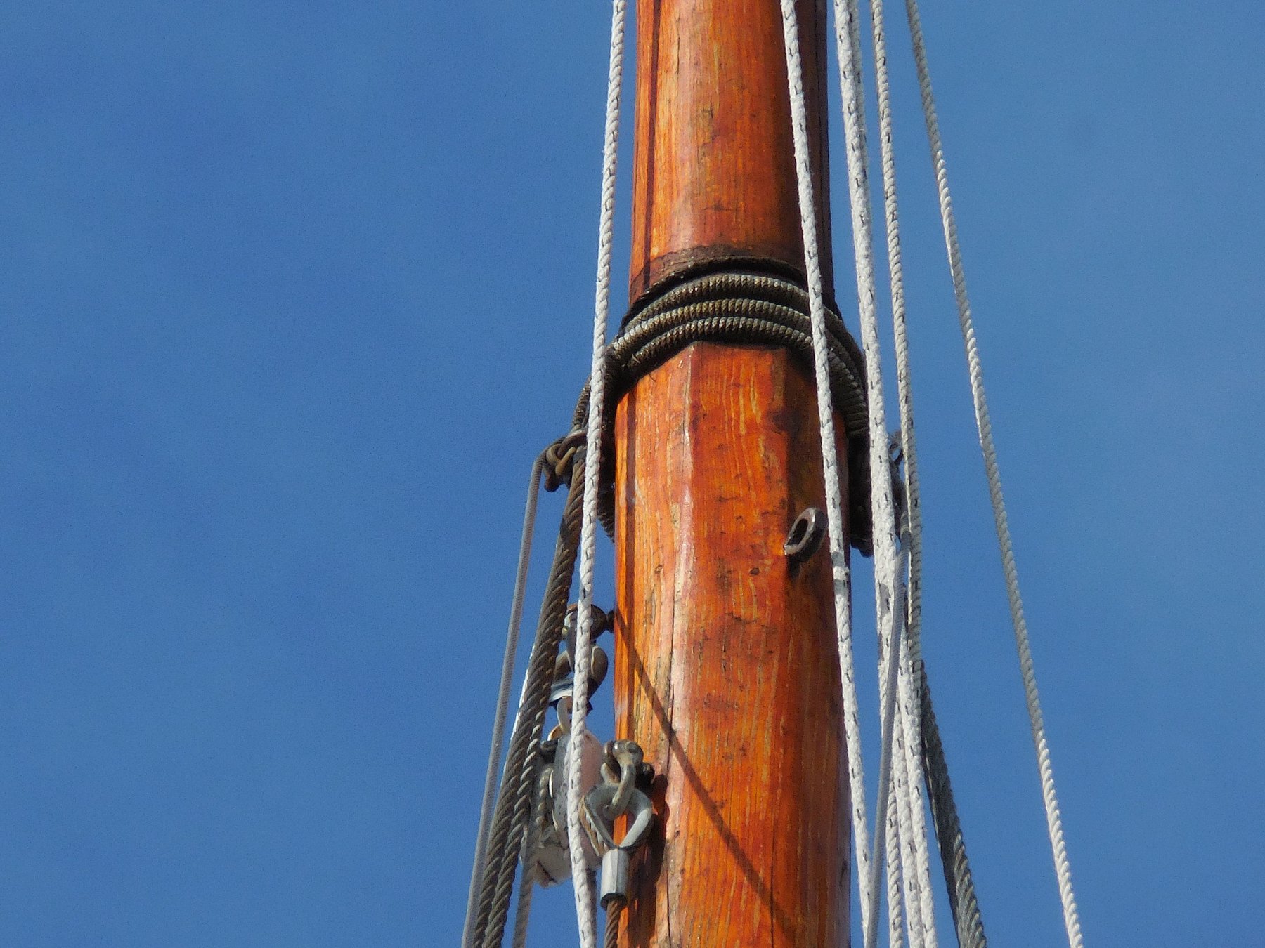
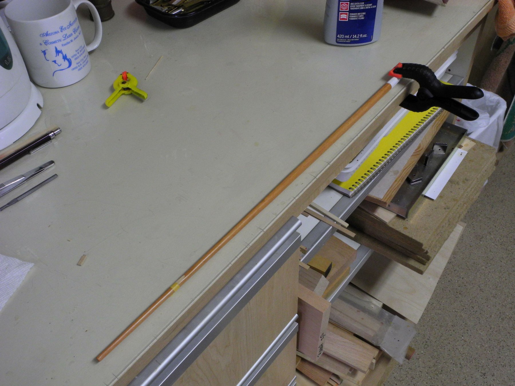
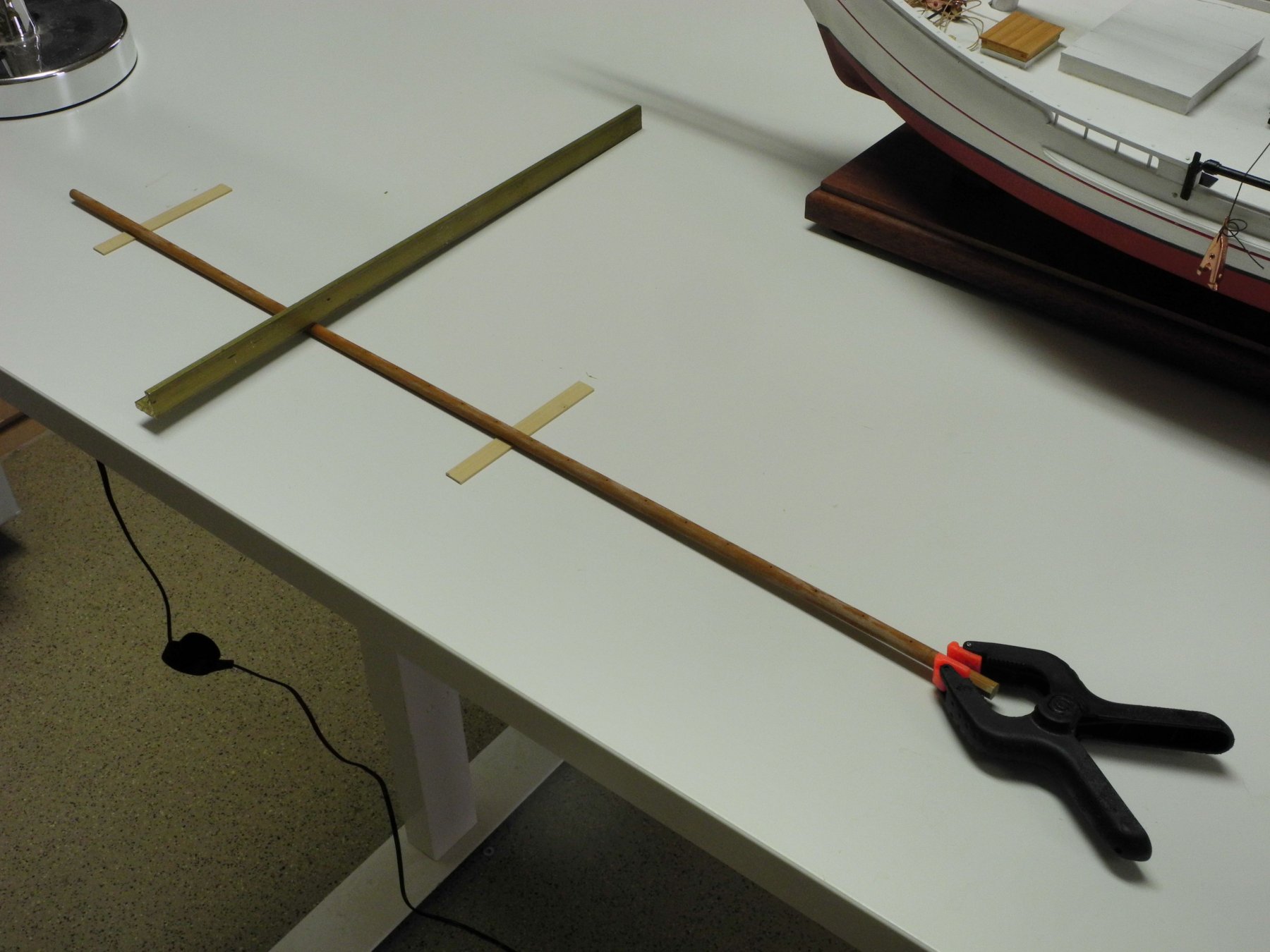
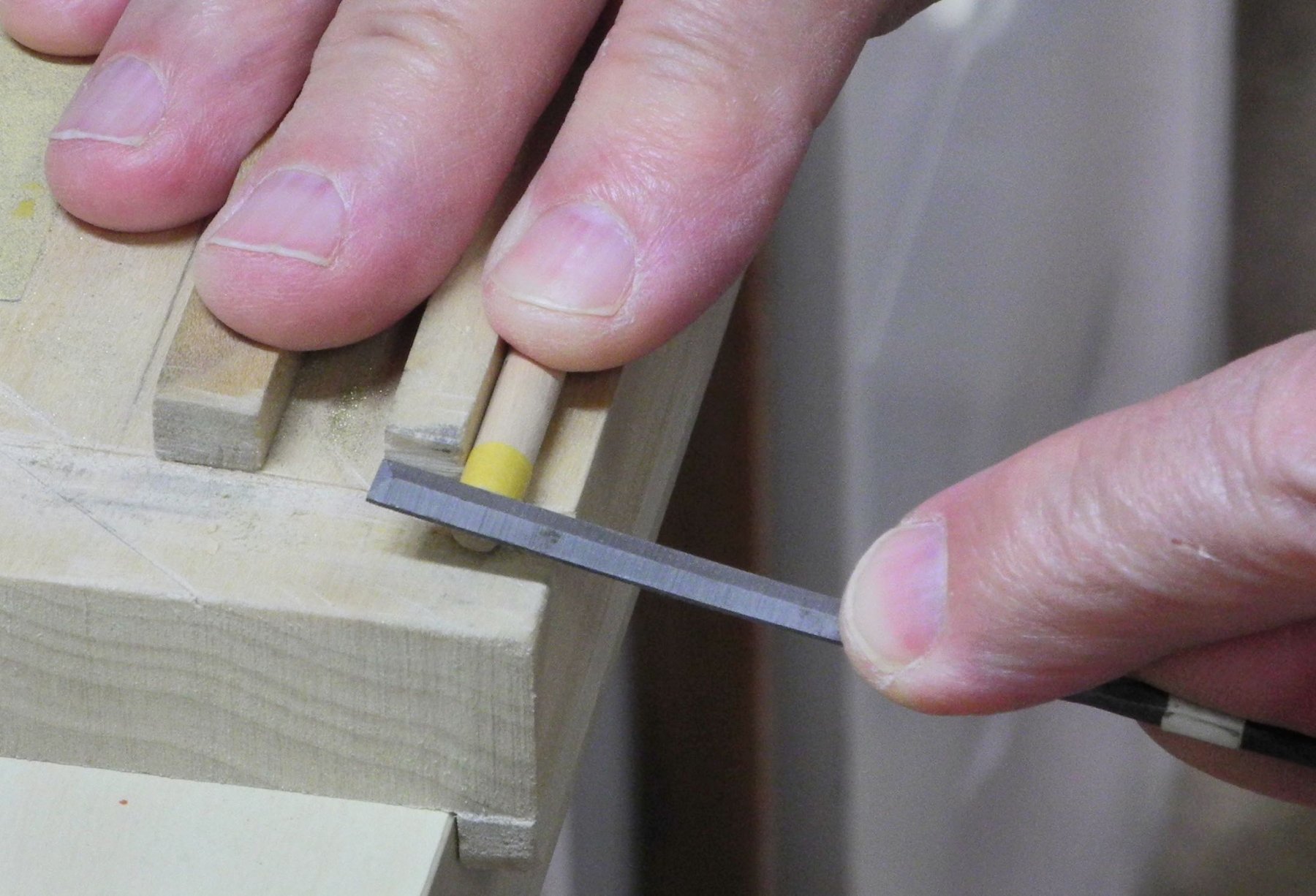
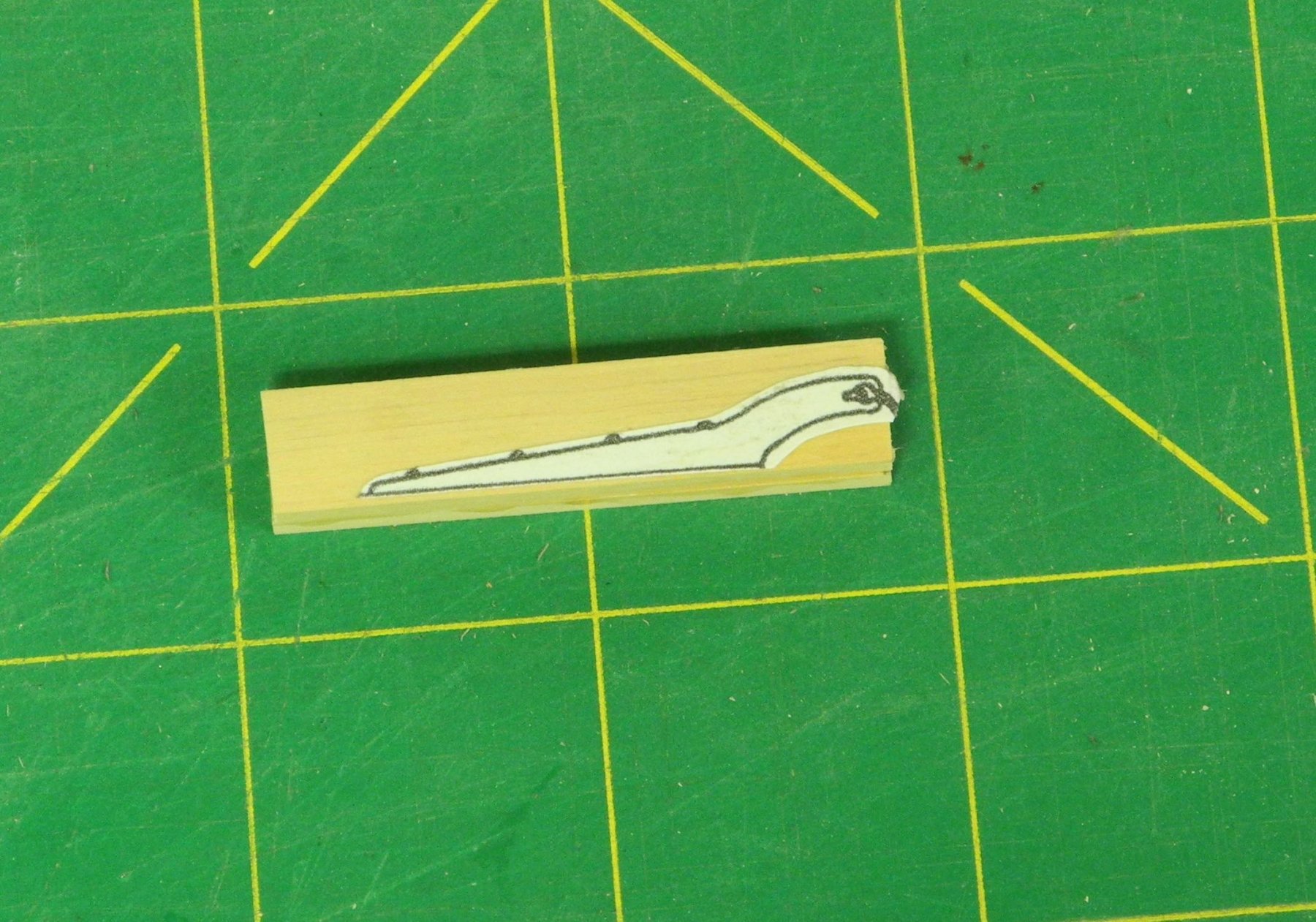
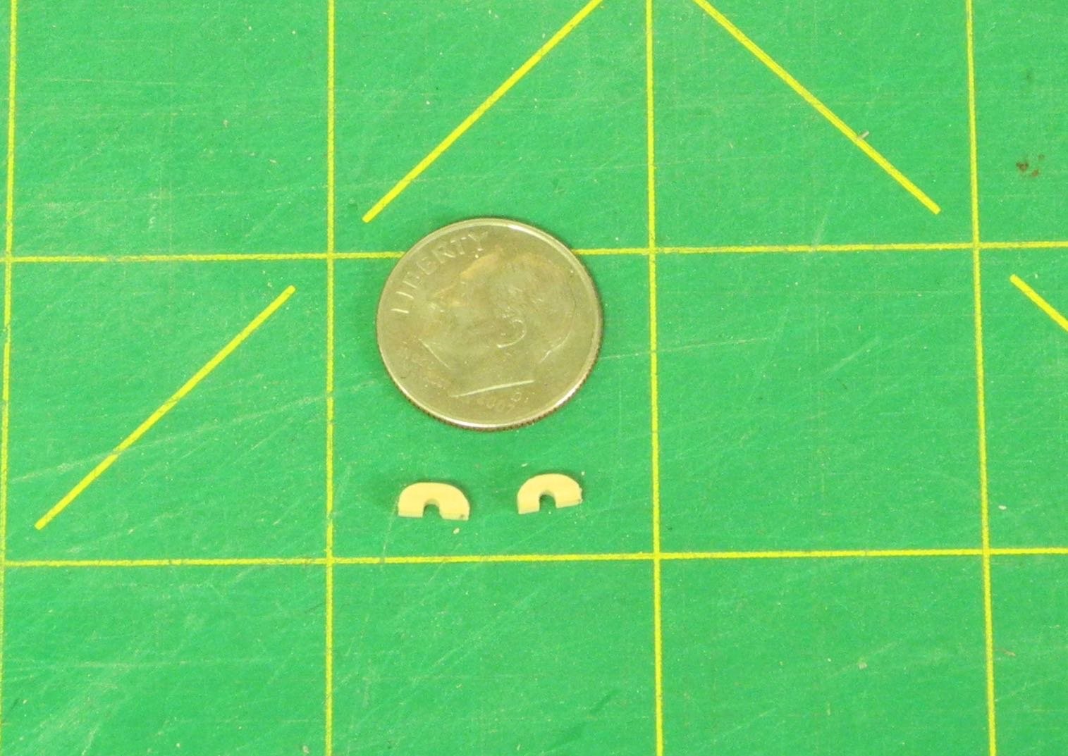
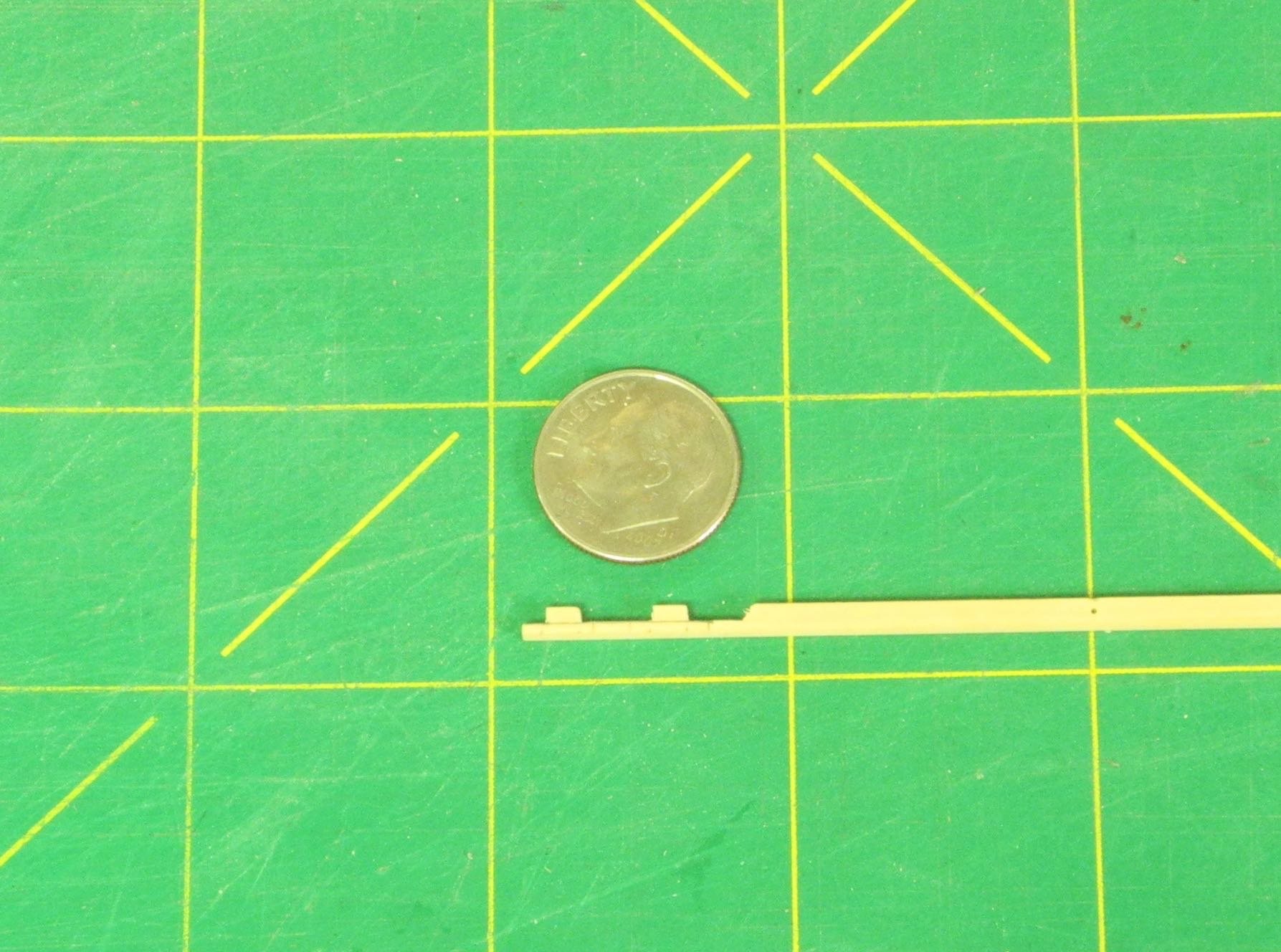
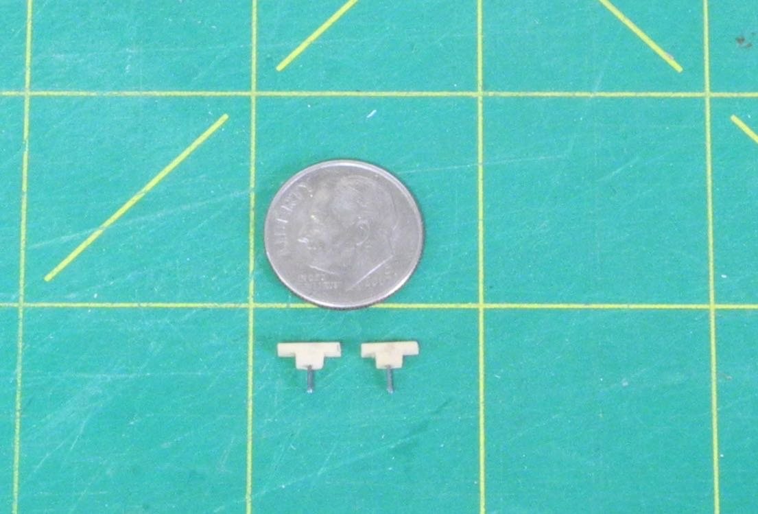
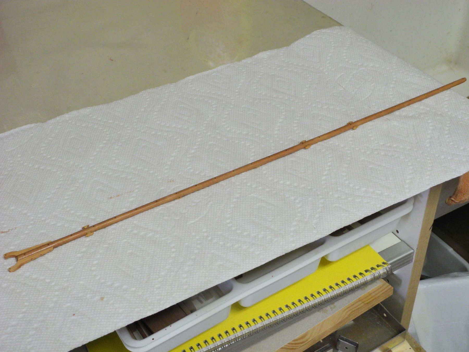
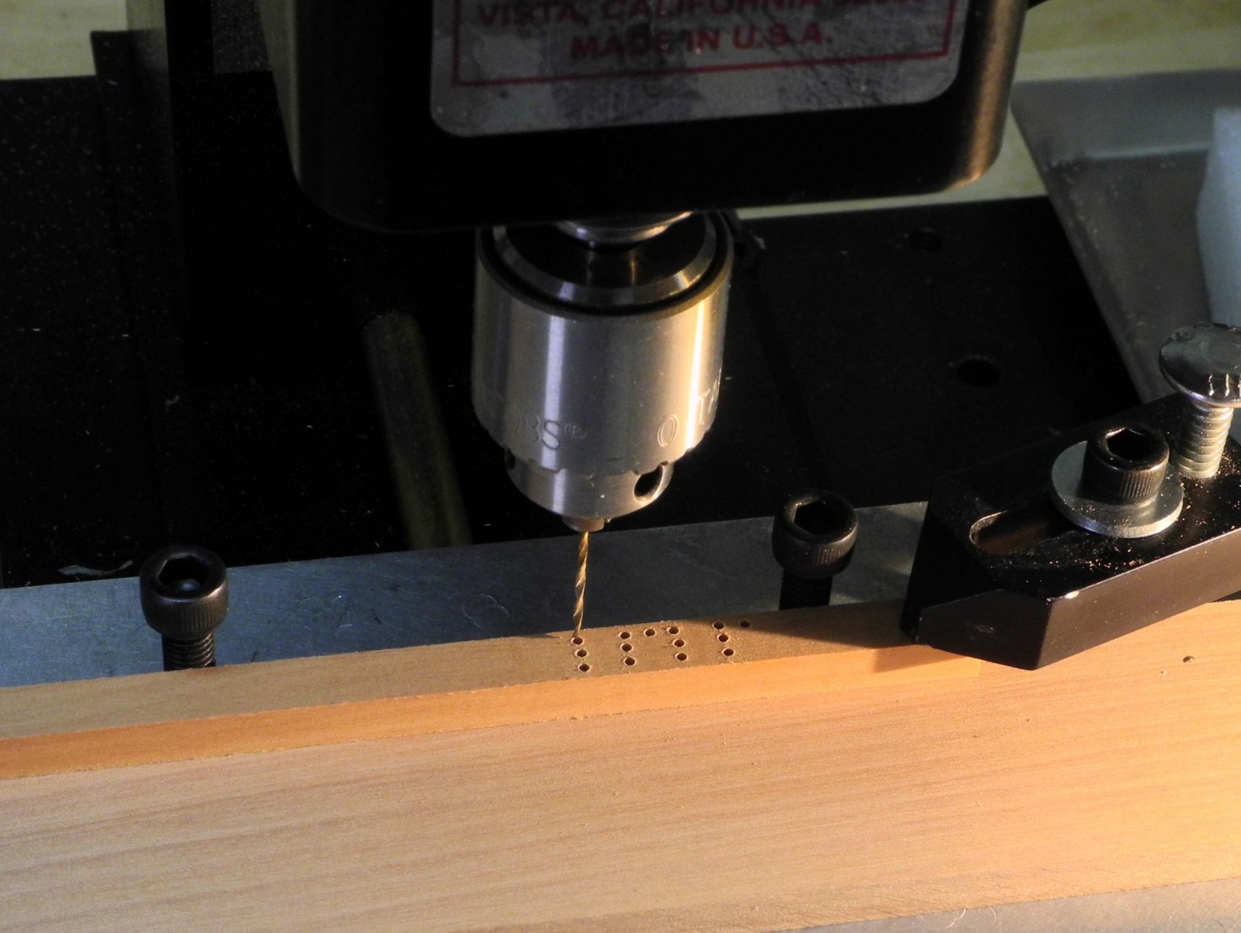
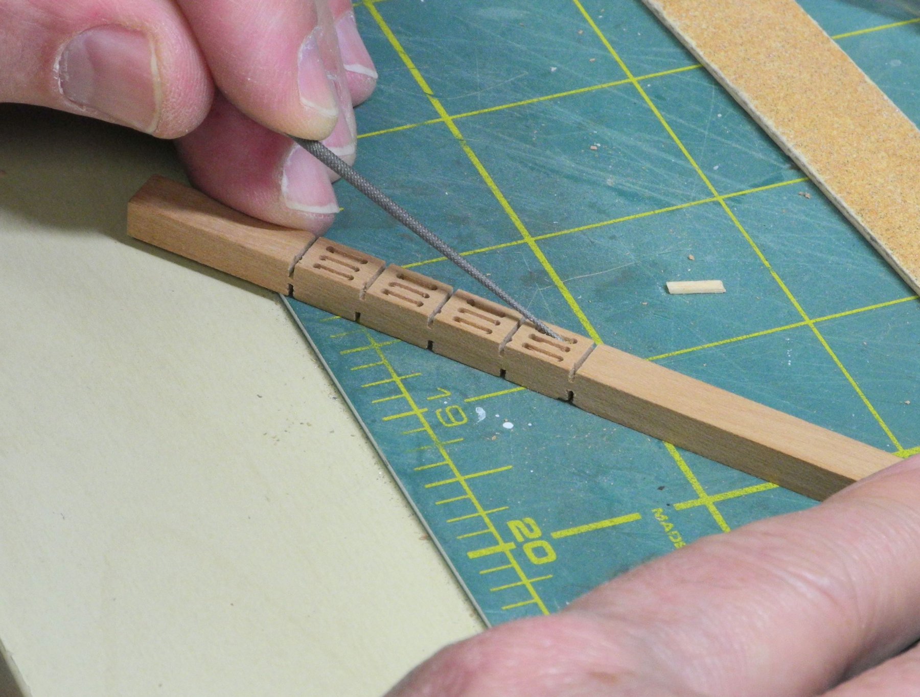
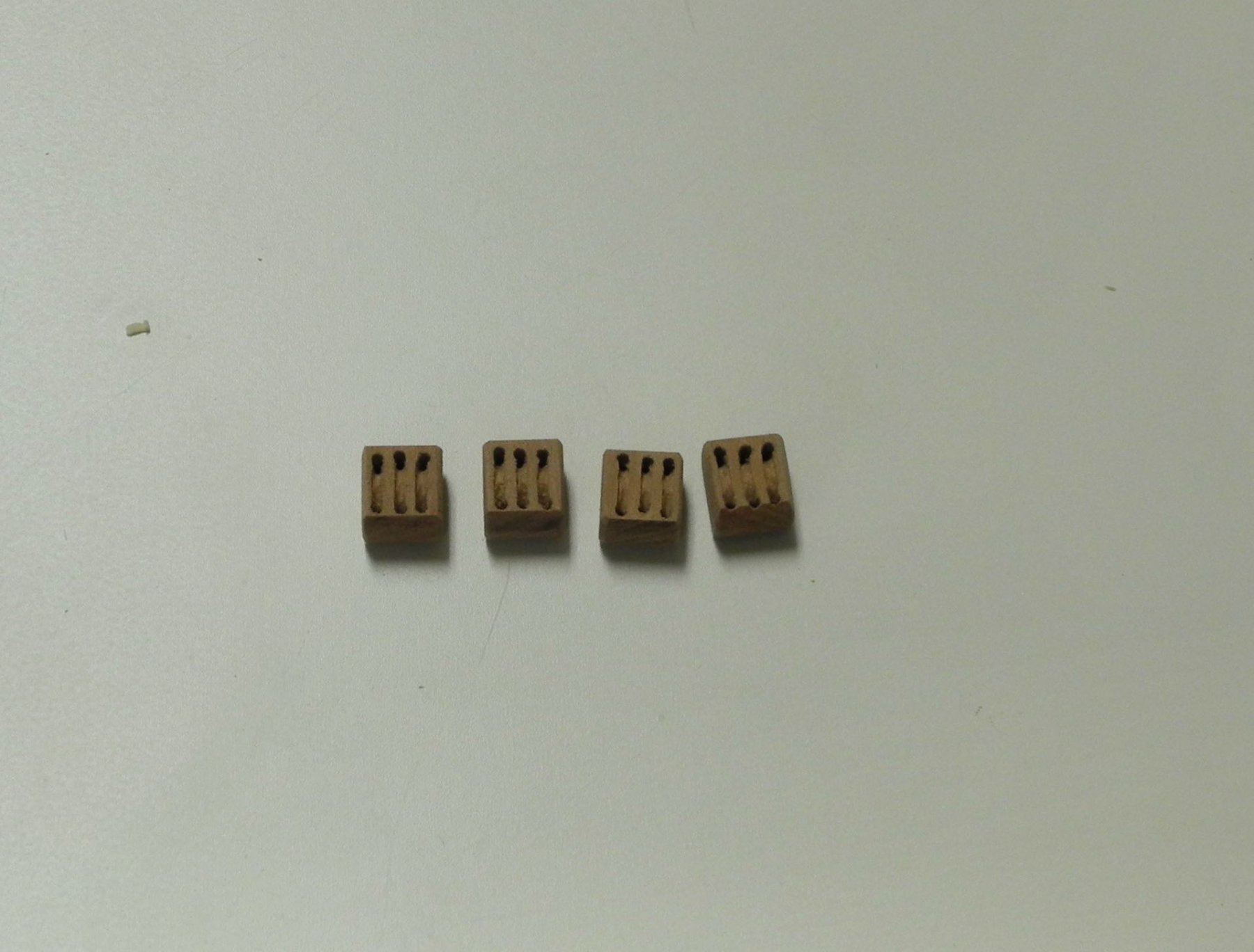
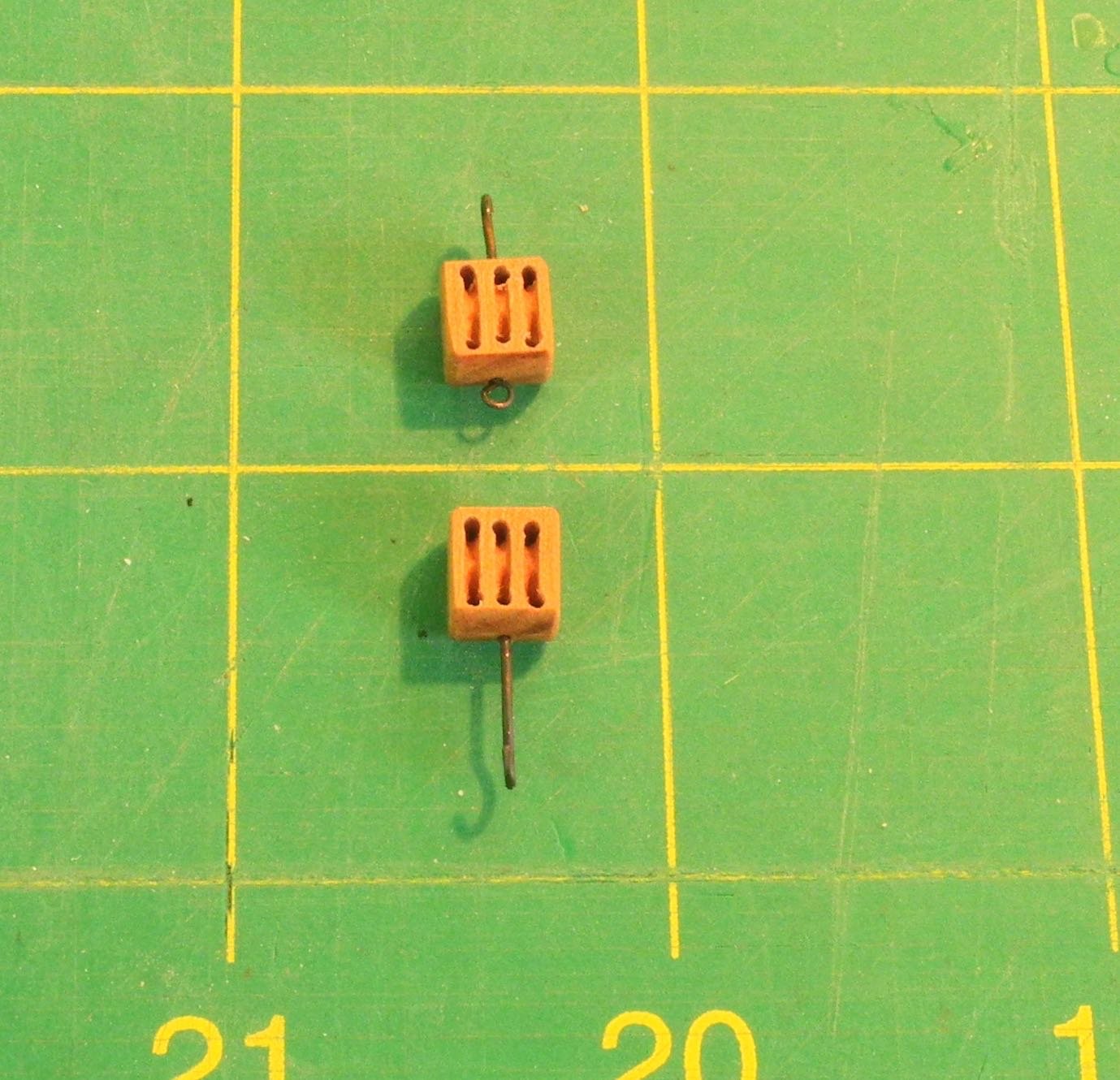
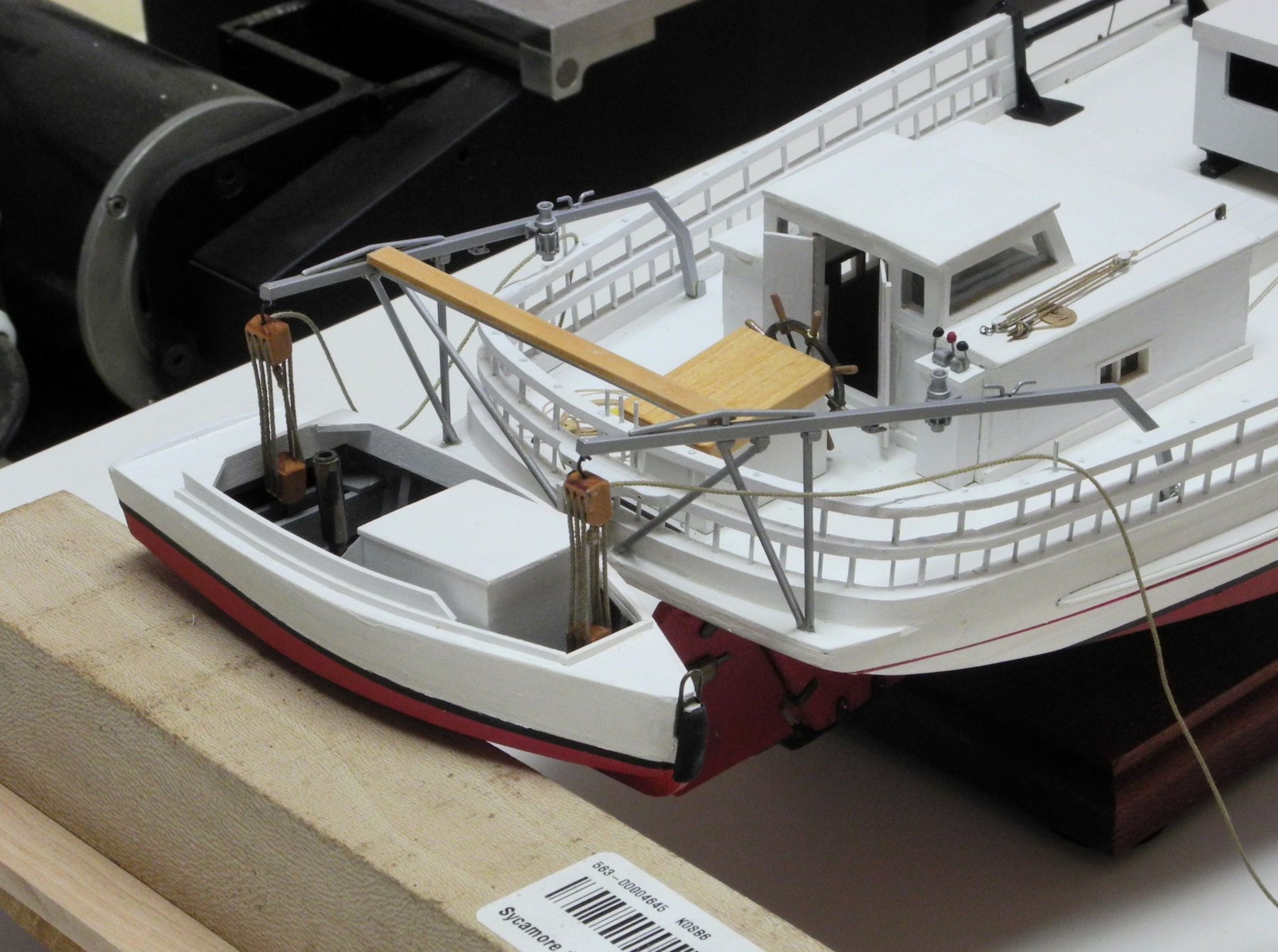
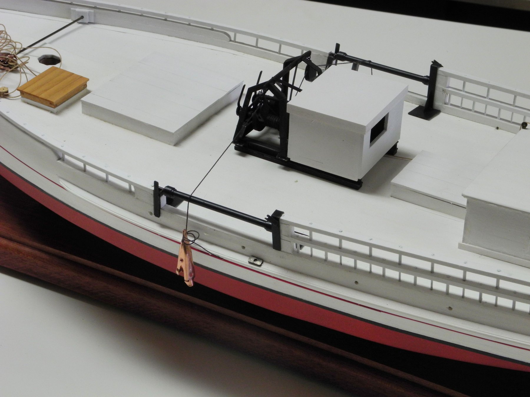
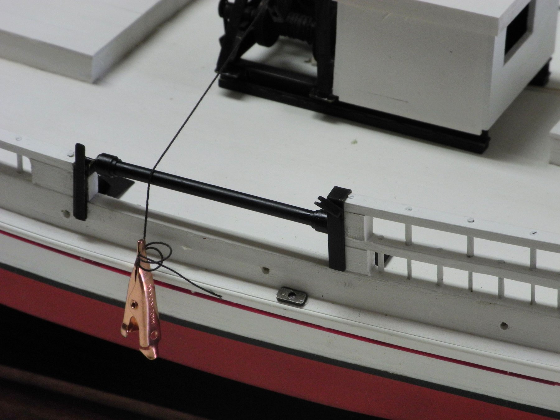
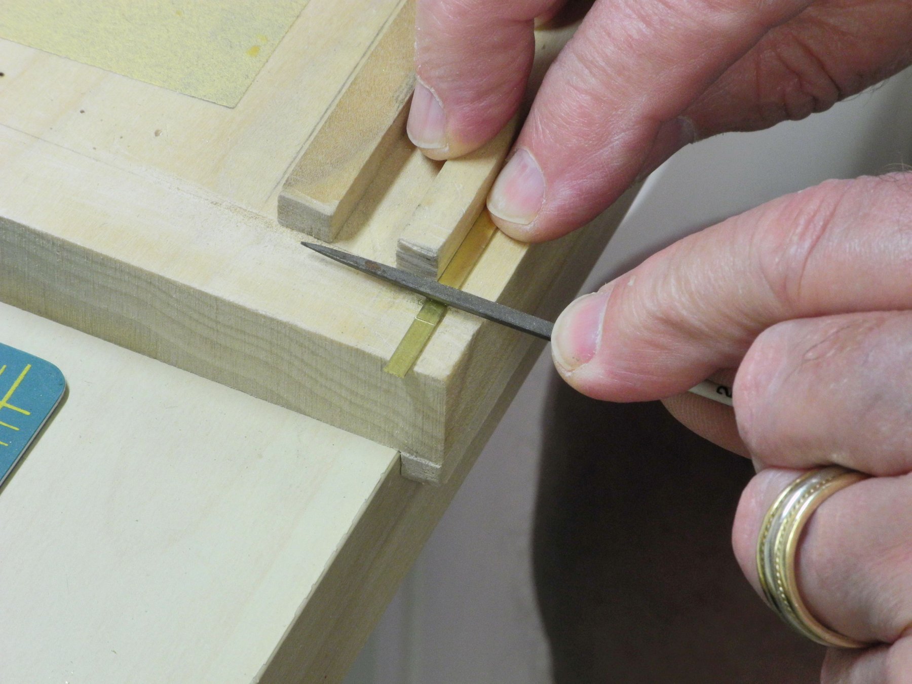
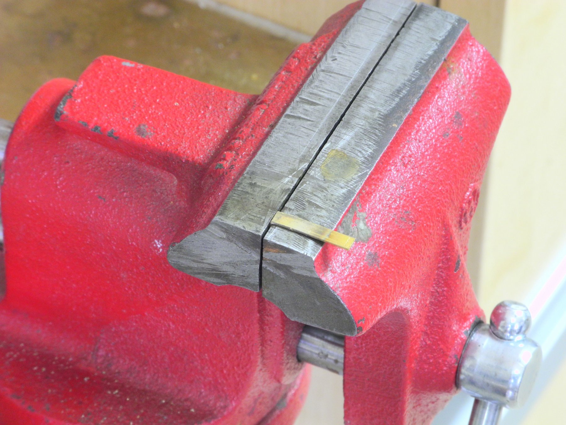
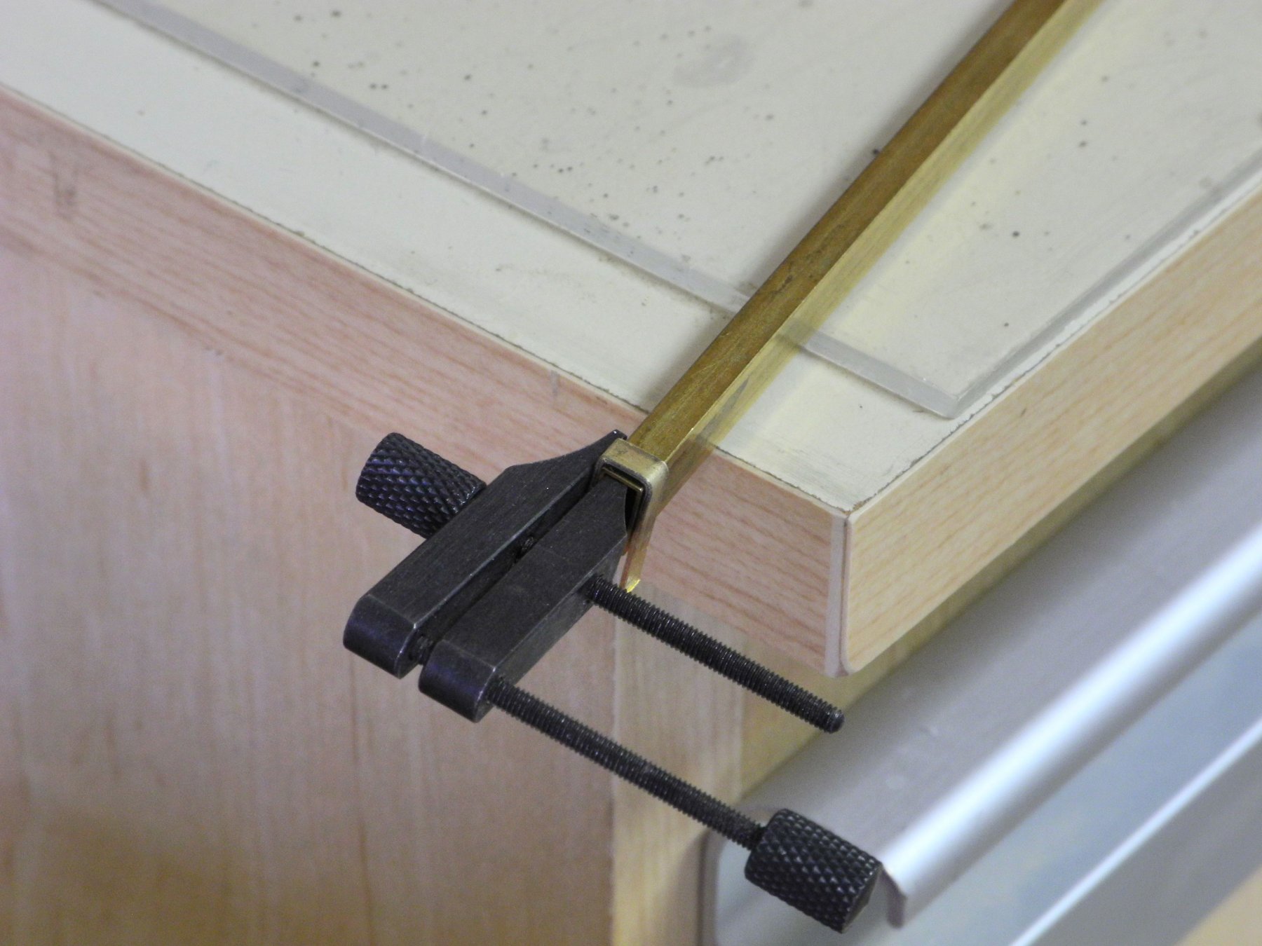
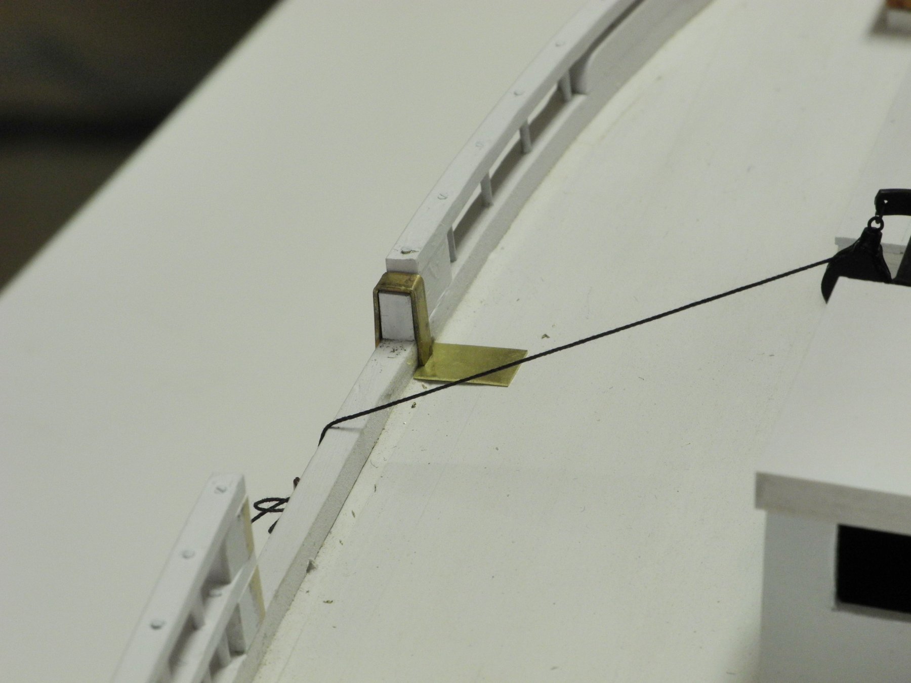
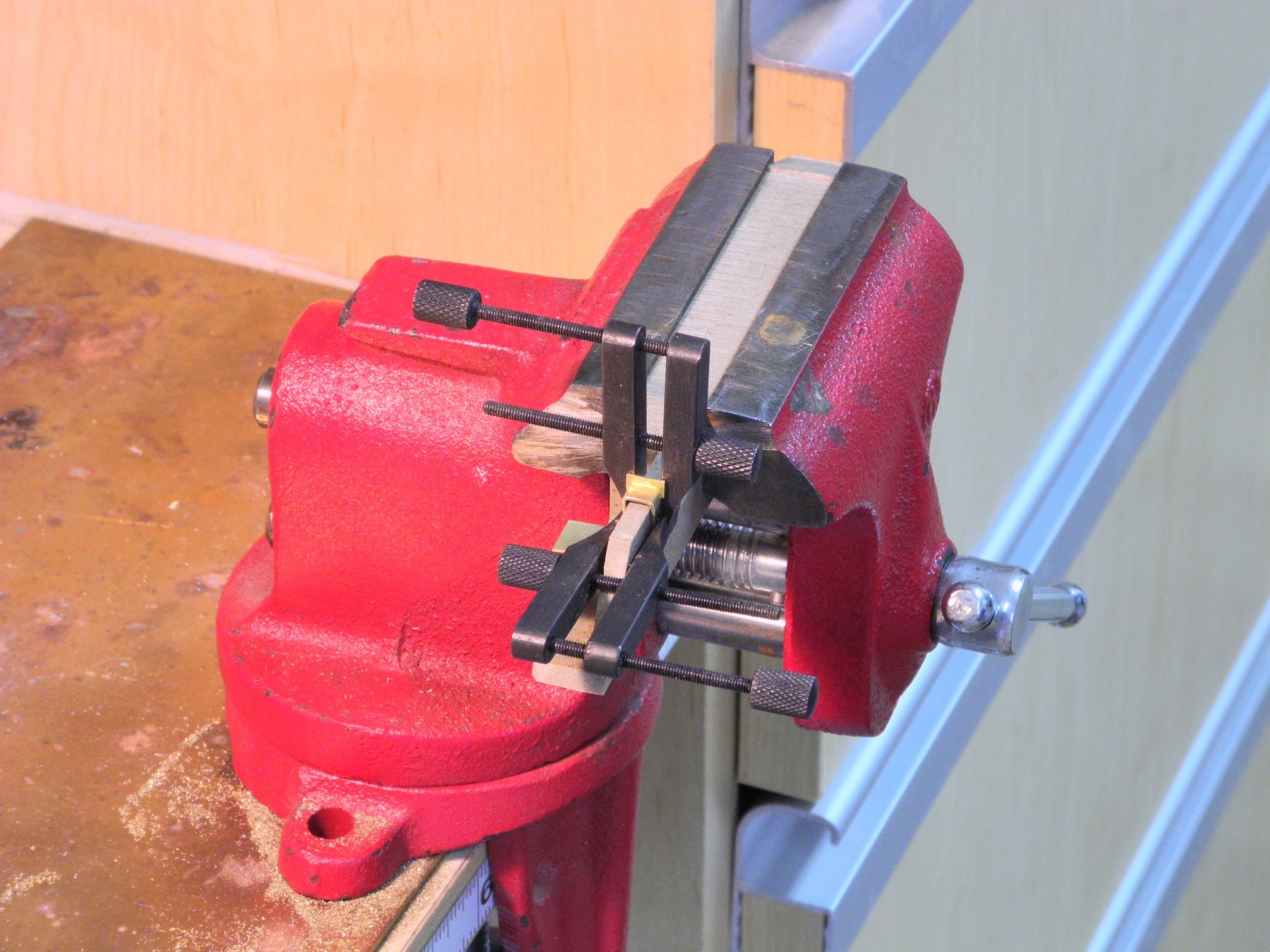
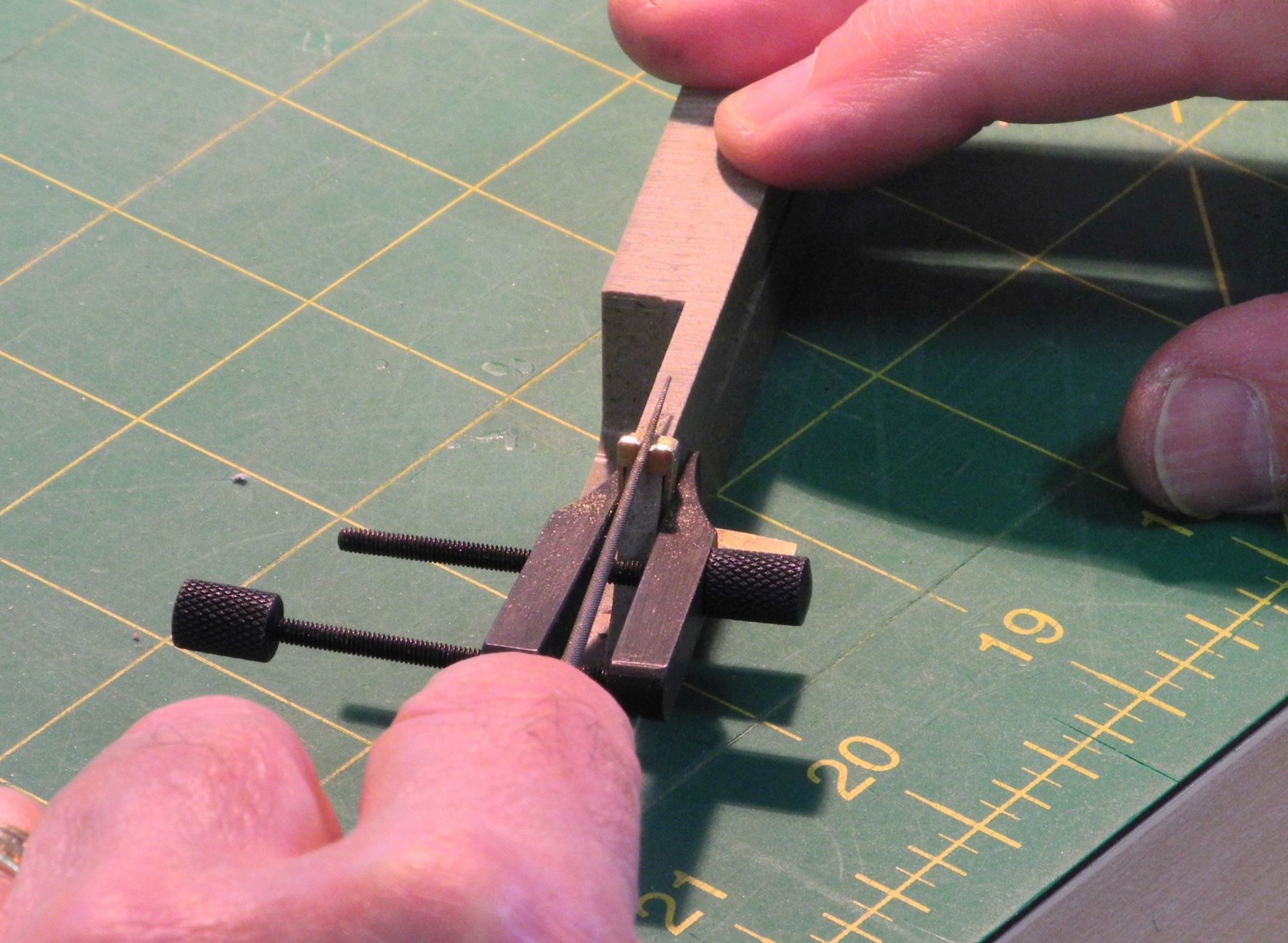
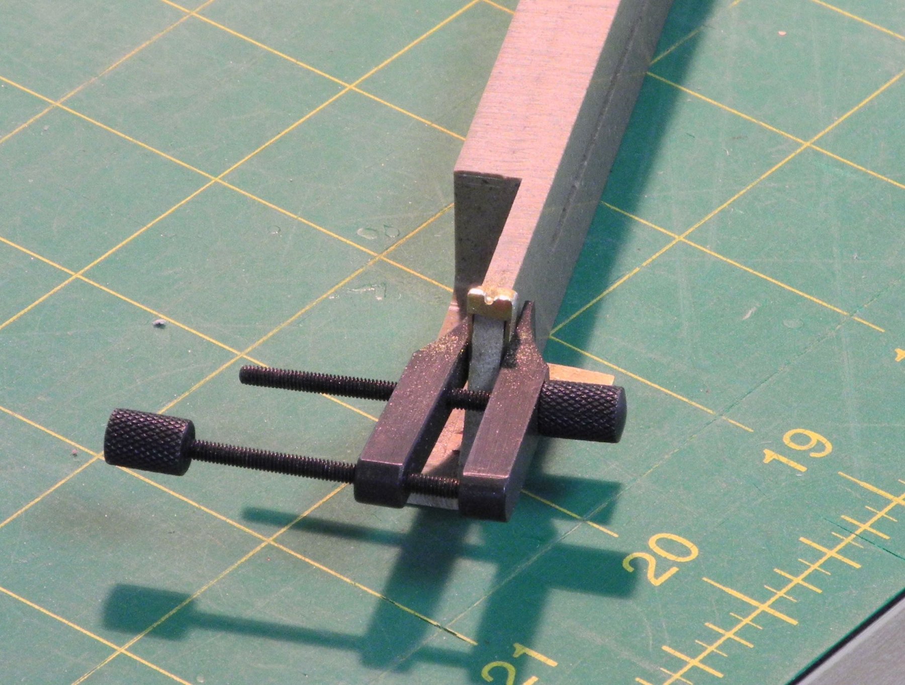
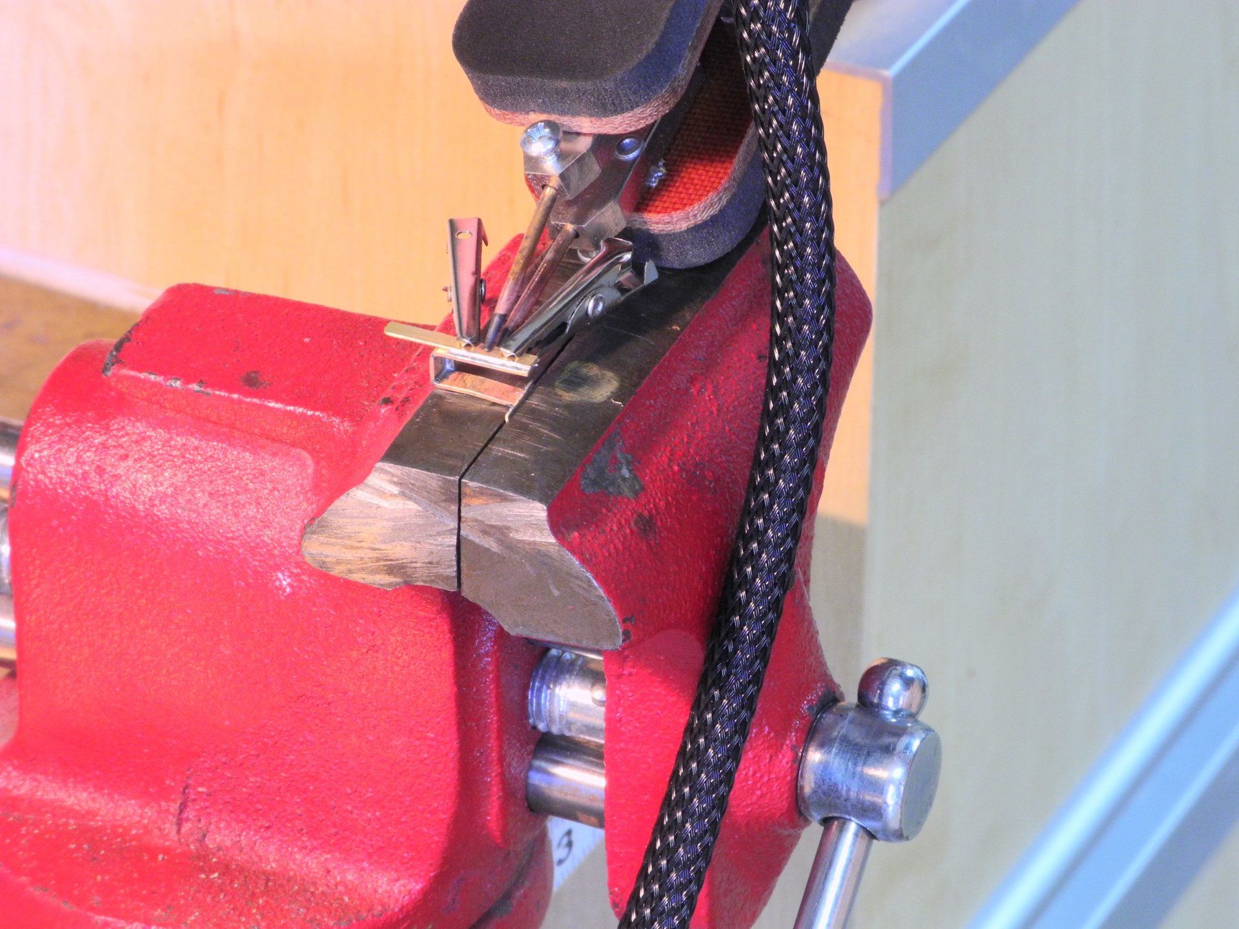
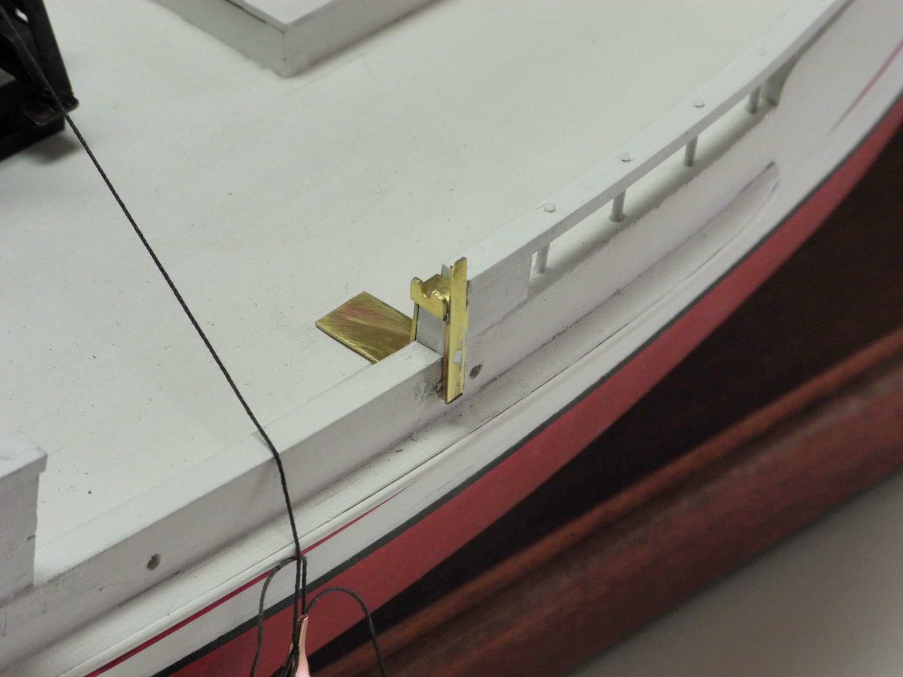
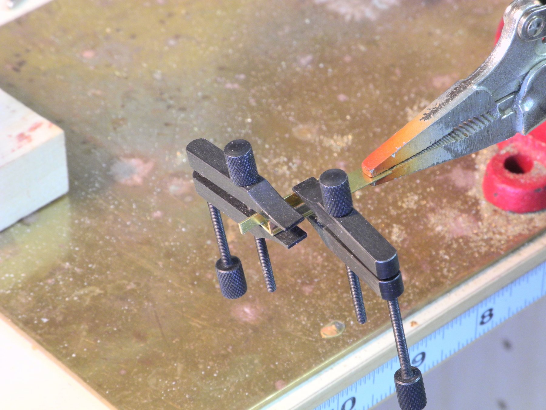
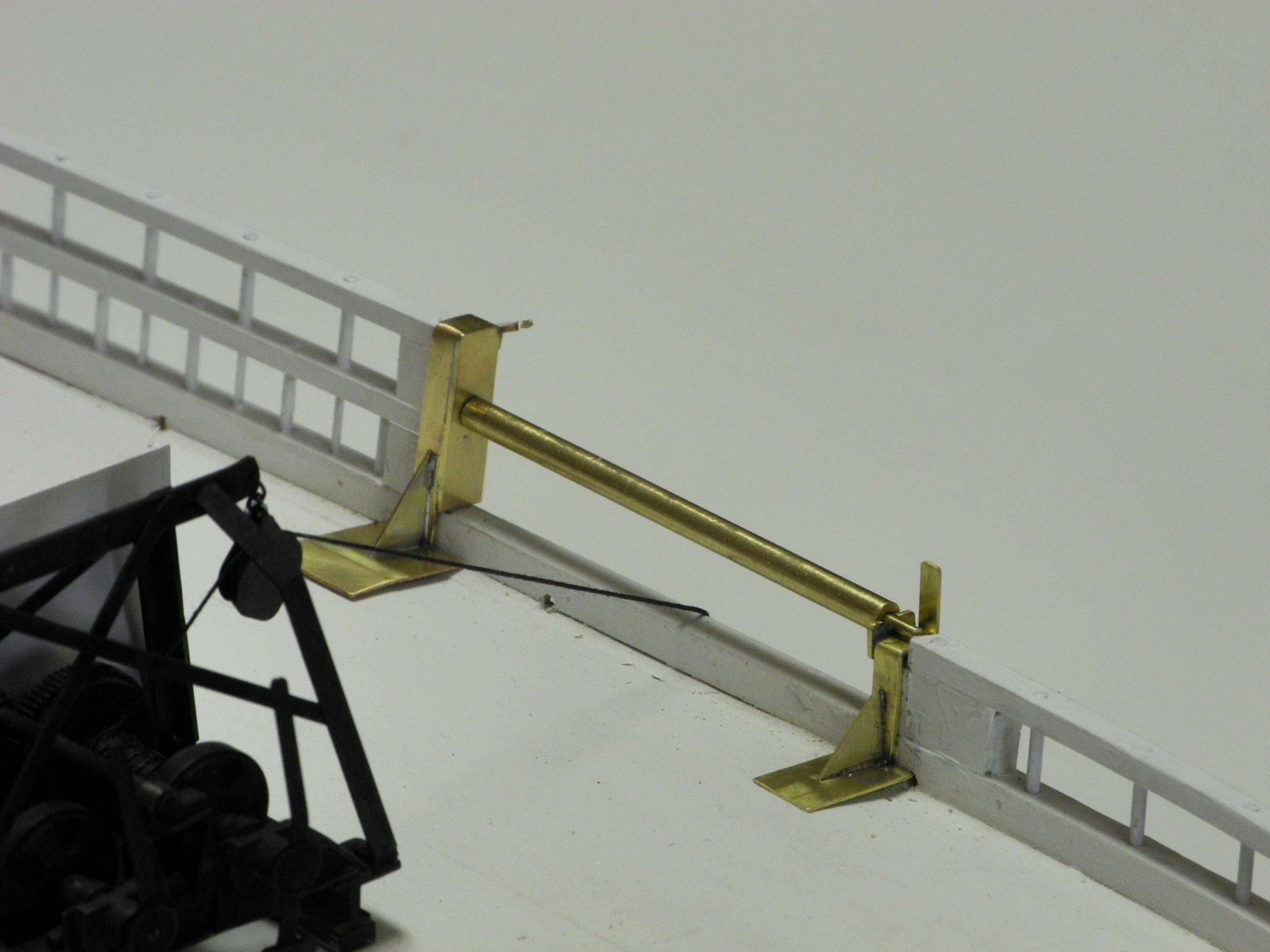
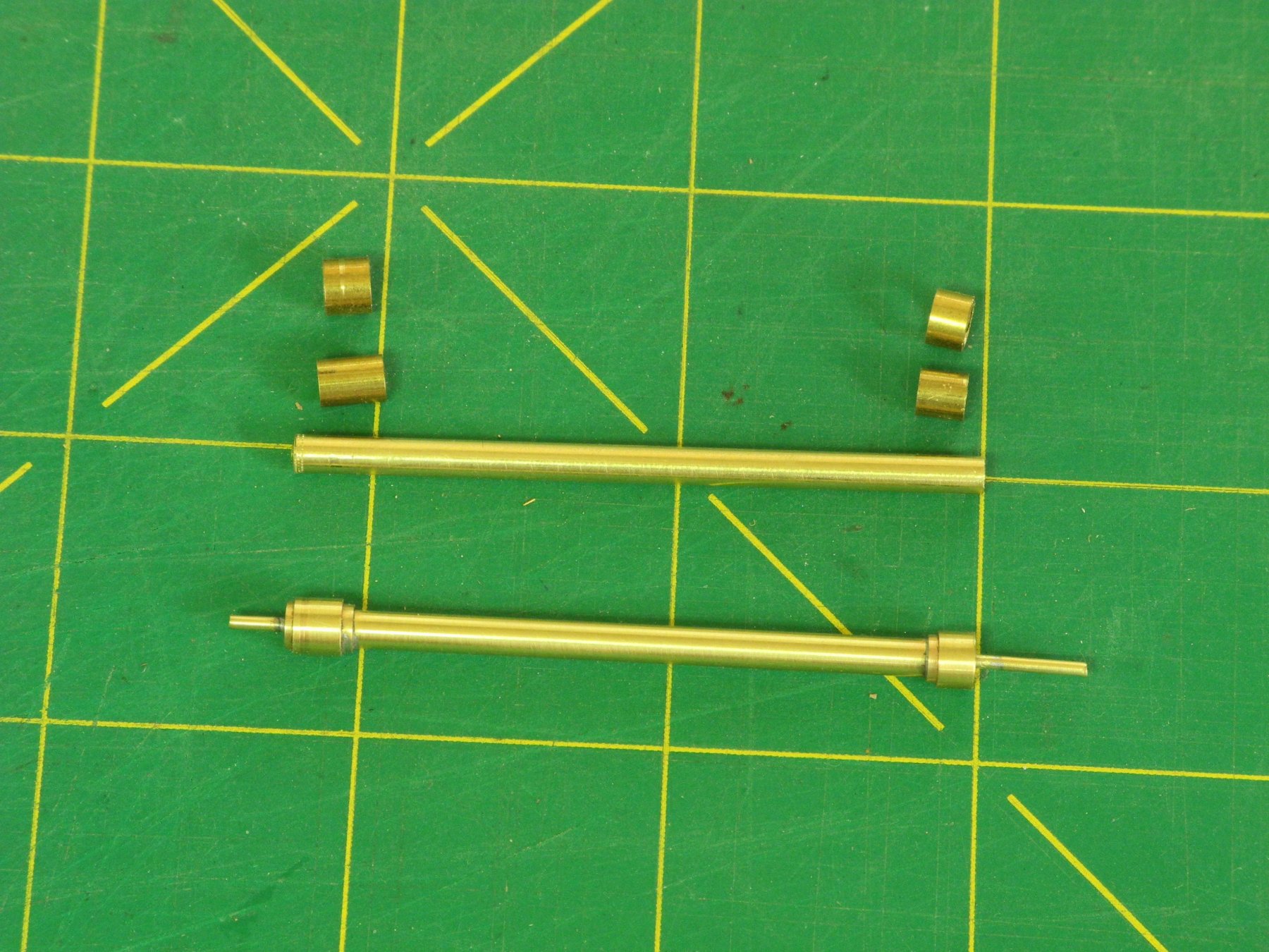
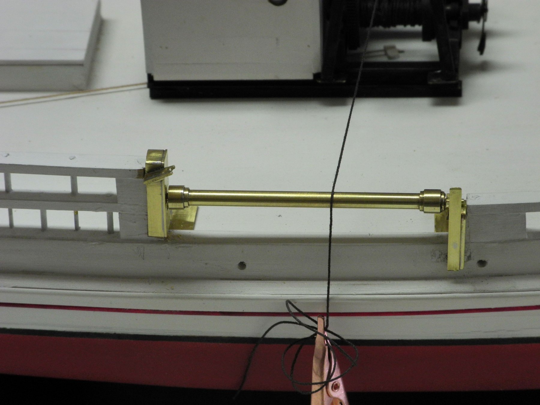
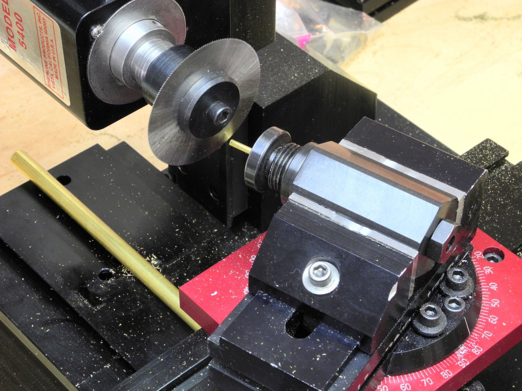
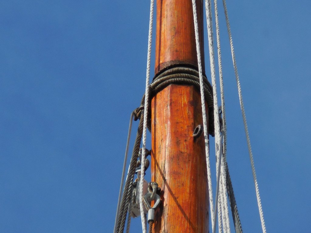
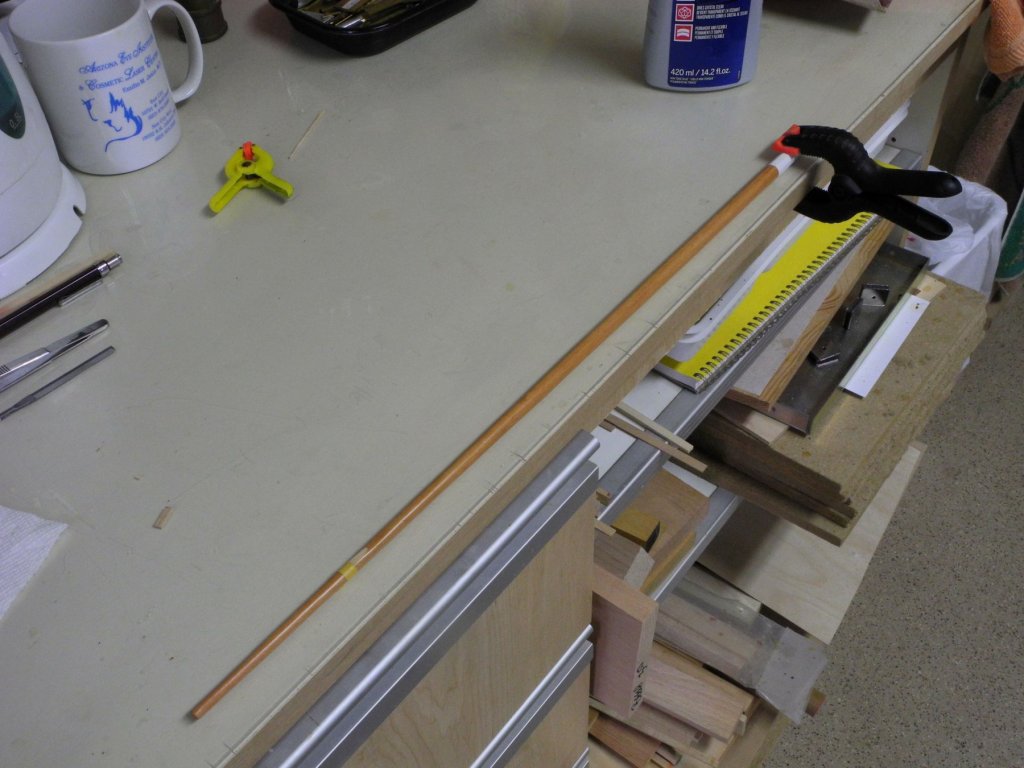
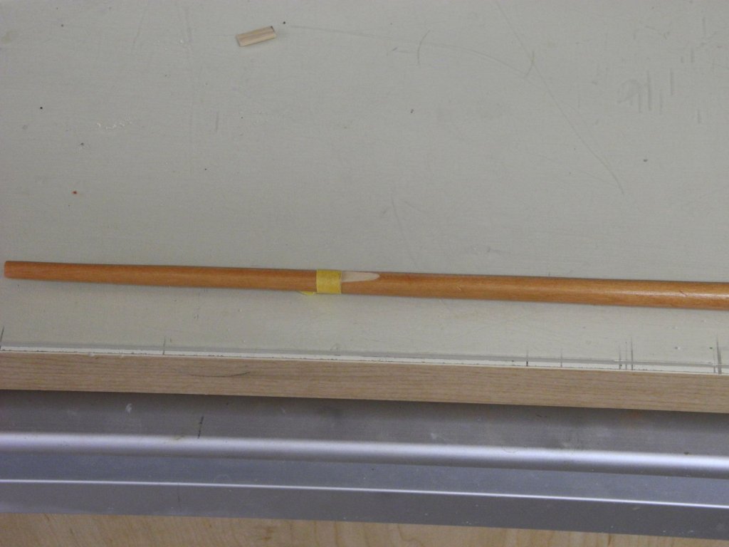
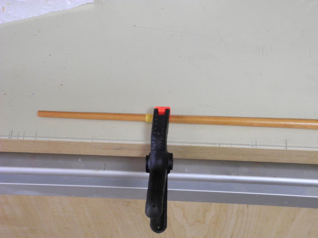
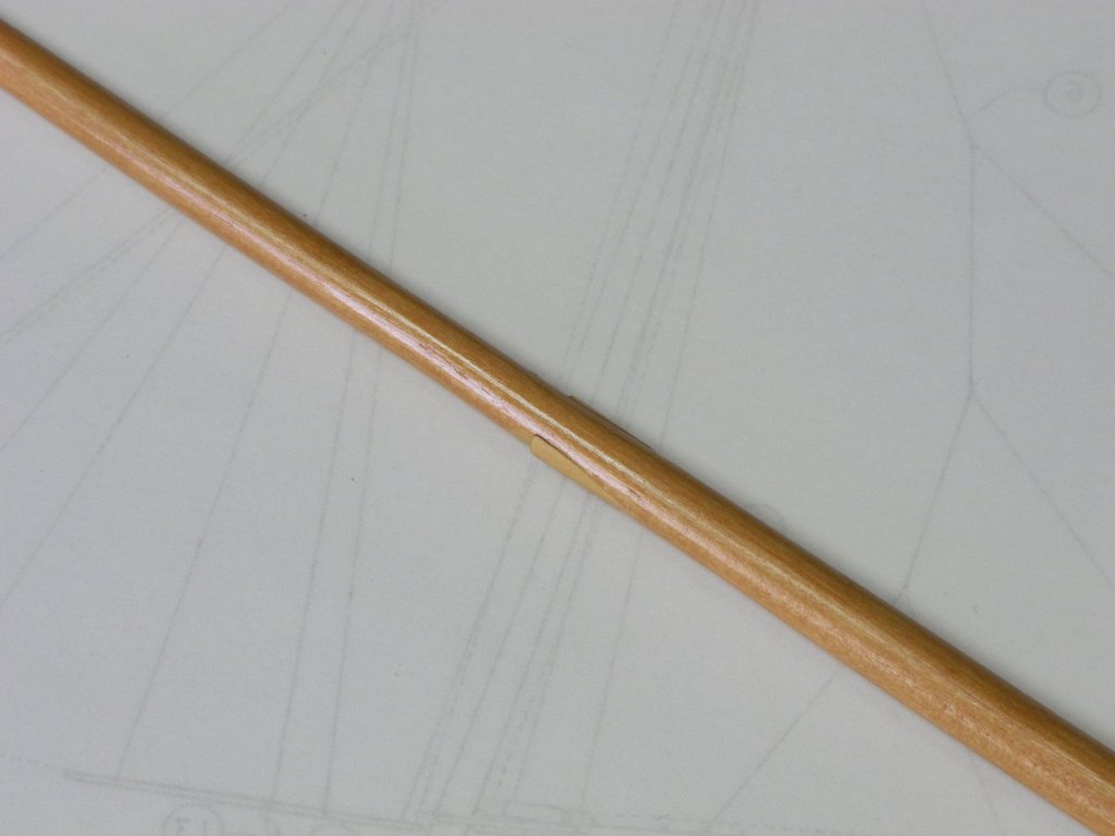
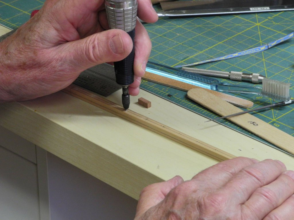
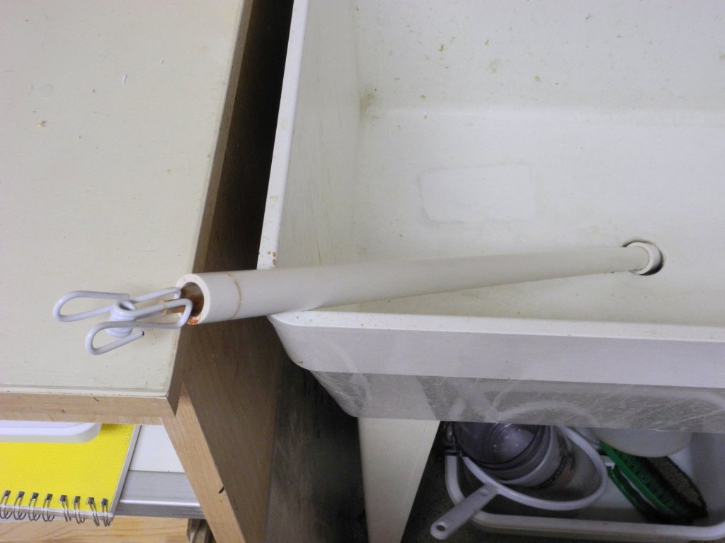
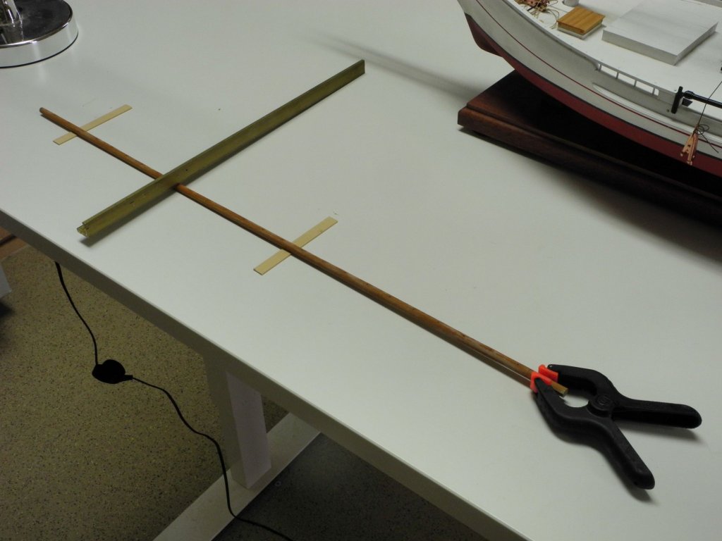
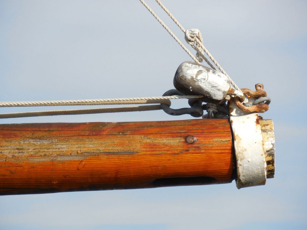
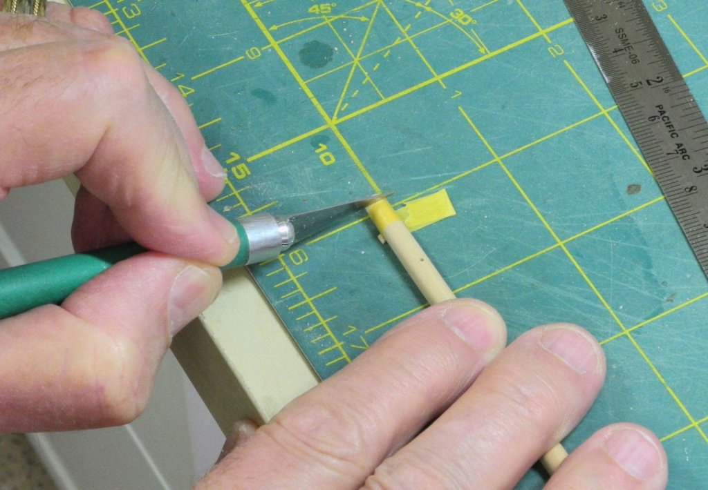
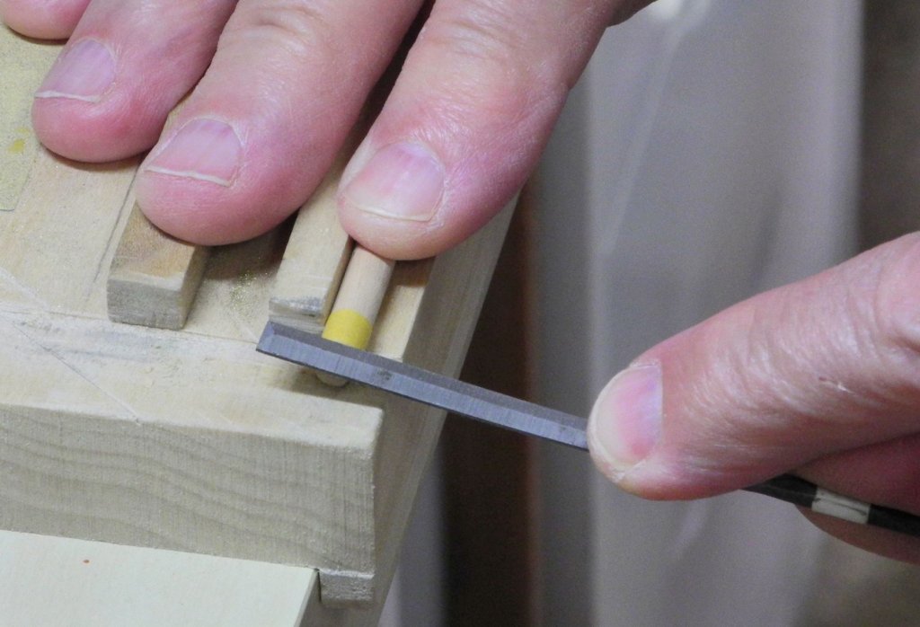
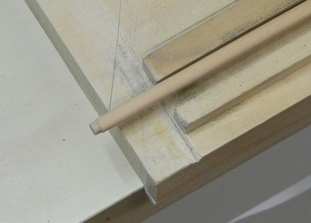
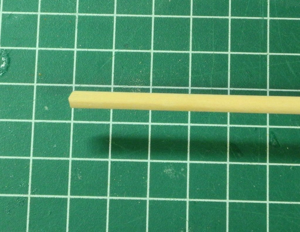
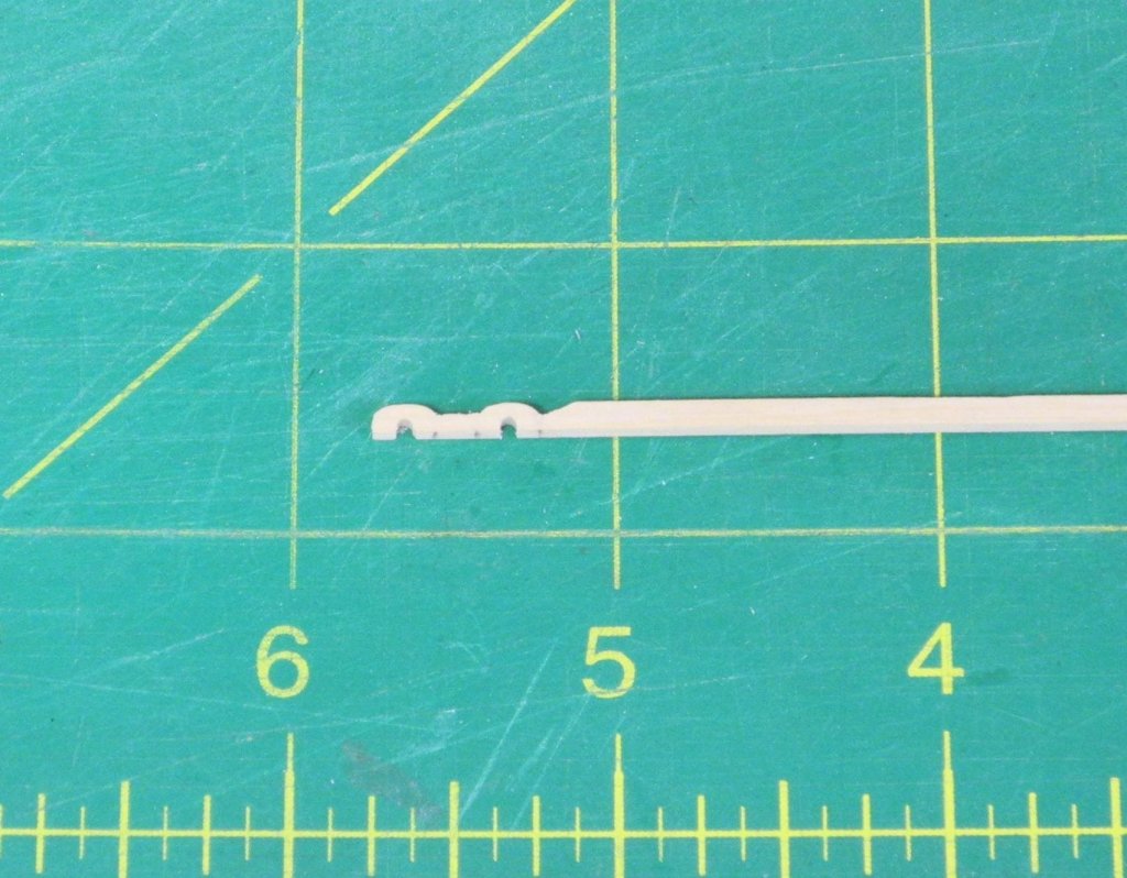
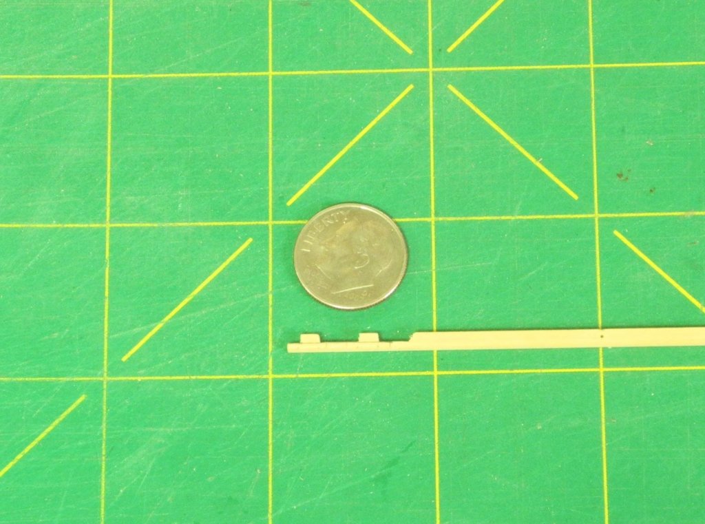
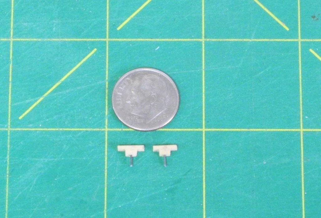
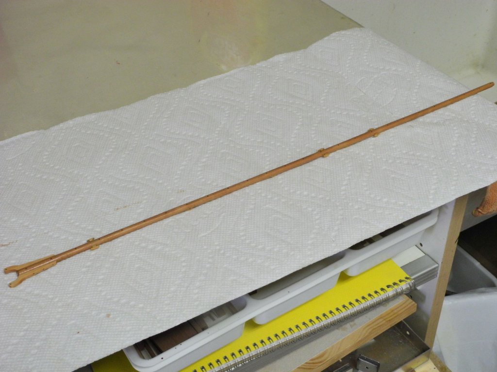
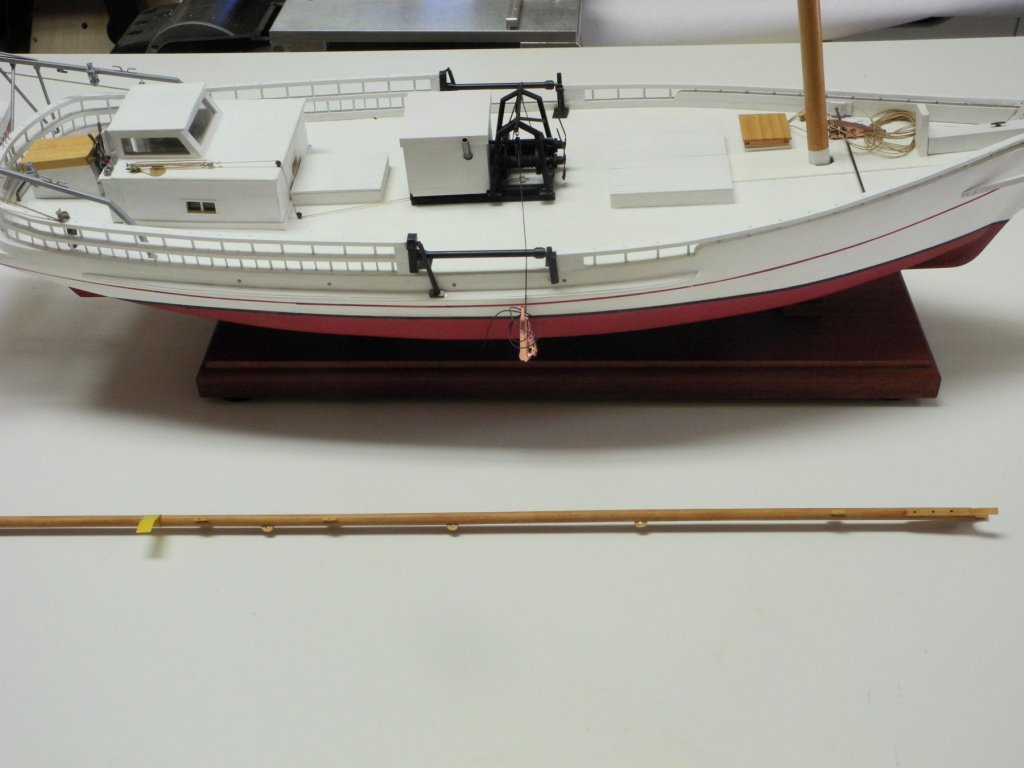
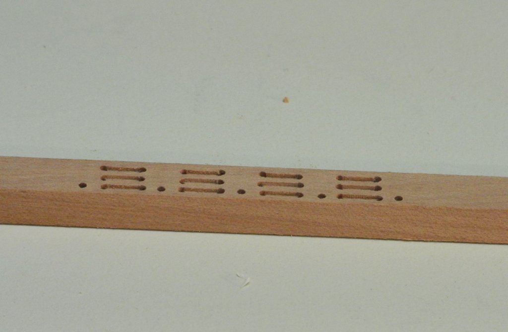
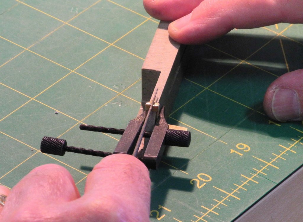
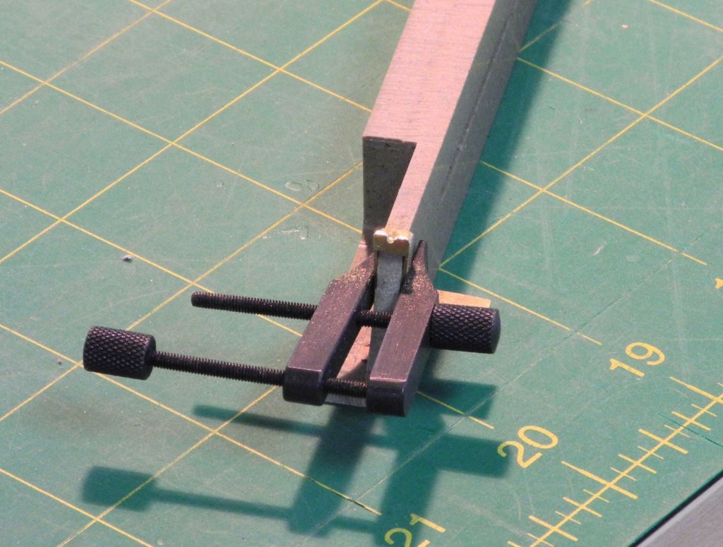
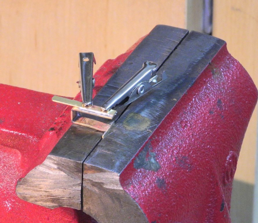
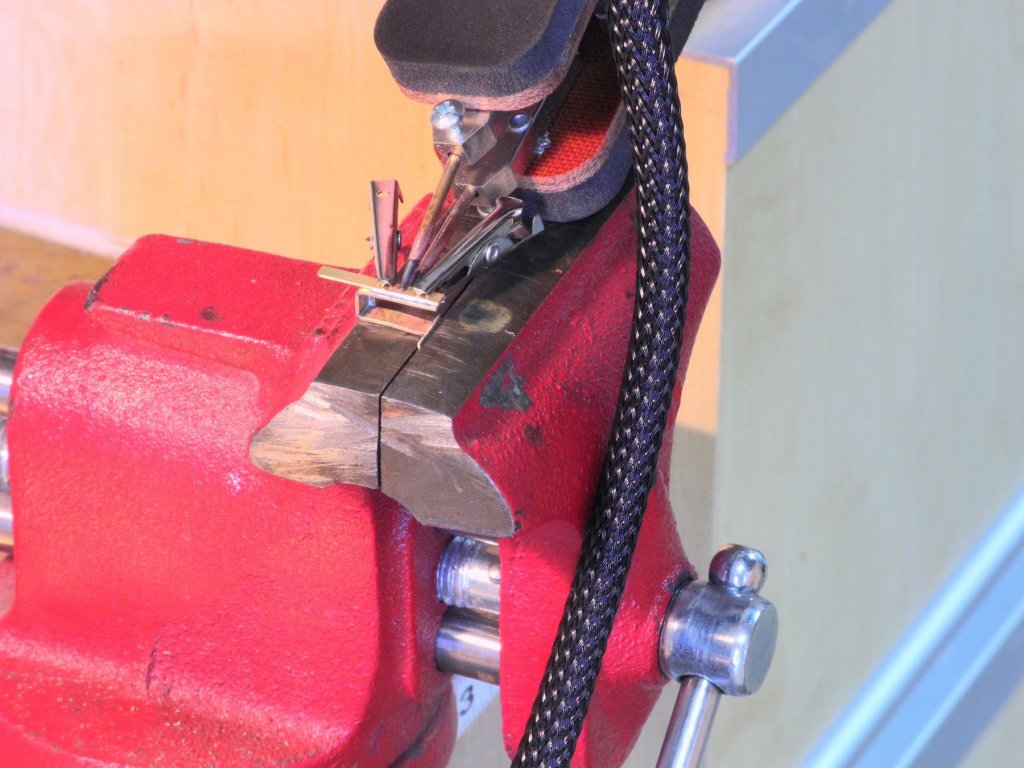
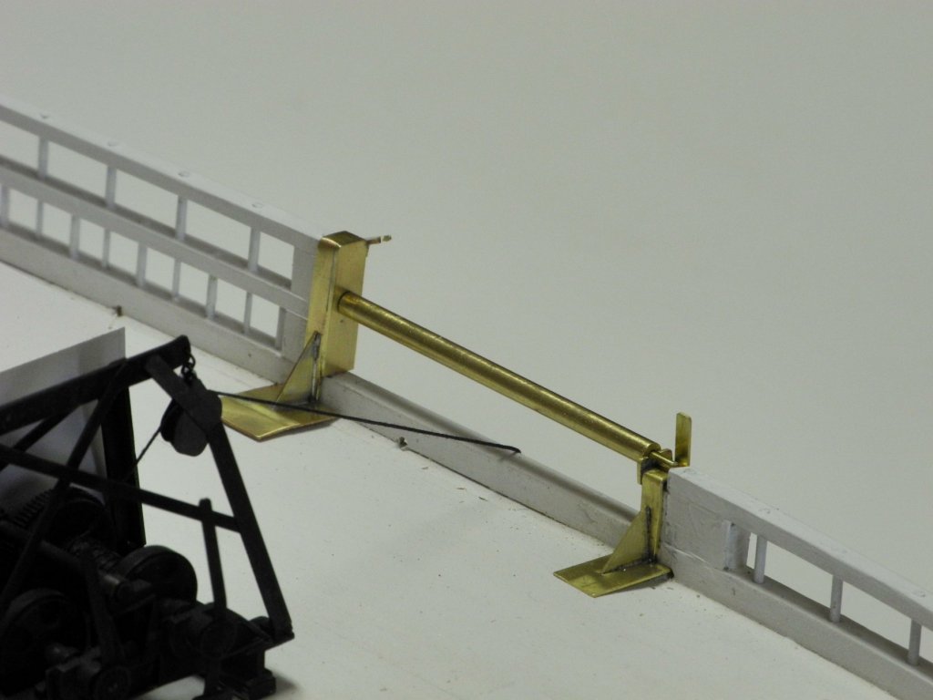
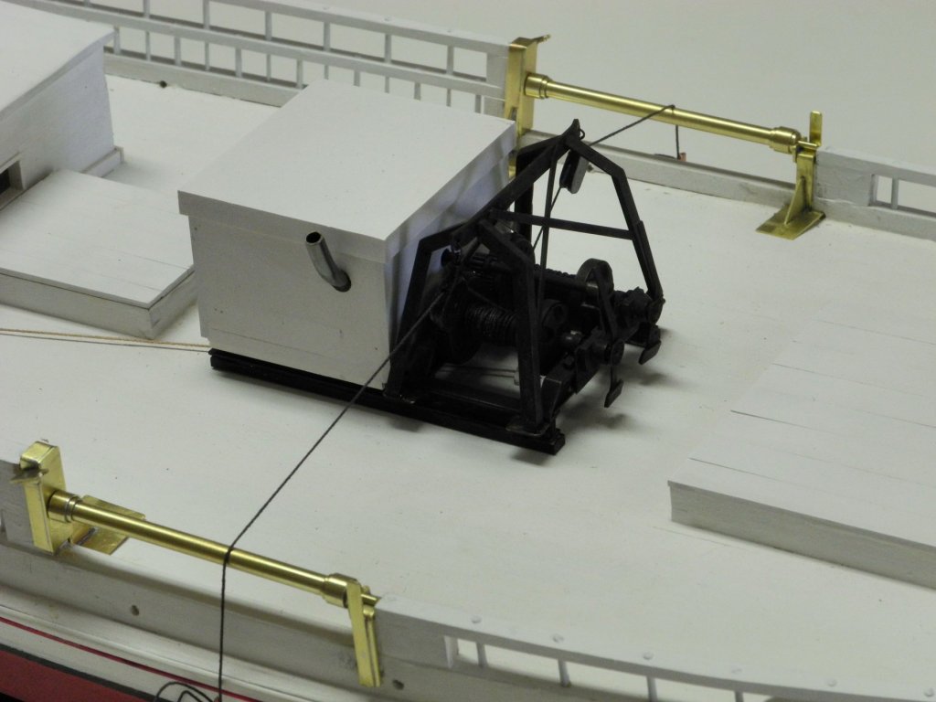
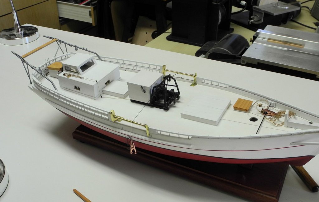
Part 66 –Mast Hounds, Boom Kathryn’s mast has very small hounds, whose purpose is to provide a landing place for the shrouds and stays. The hounds are barely visible in the following photo of Kathryn’s mast. Making the hounds was a simple process. Narrow tape was wrapped around the mast to indicate the top of the hounds. This ensures that the hounds on each side of the mast are at the same height. The mast was clamped to the bench to make sure the area for the hounds were properly on the side of the mast. The area for the hounds was then cut in and flattened. A small piece of matching stock was glued in place and then shaped, stained, and finished with wipe-on poly. Kathryn’s boom is fairly complex, with a number of cleats and fairleads besides the jaws, and with some metalwork. There are ringbolts located every 24 inches along the top of the boom. The boom was shaped from square stock, and after shaping it to the outside dimensions, holes for the ringbolts were drilled in the top surface. The boom was rounded in the same way as the mast, using the 7-10-7 process illustrated in part 30. https://modelshipworld.com/index.php?/topic/15453-skipjack-kathryn-by-mahuna-132-based-on-haer-drawings/&page=9 The following photo shows the rounded boom temporarily laid on Kathryn. The booms on these old skipjacks (and many other ships as well) are no longer perfectly straight, even if they started out that way. Over time, the weight of the sail and the boom itself, will cause the slender boom to bend. In an effort to make the boom more realistic, a slight bend (about a scale 1 inch) was introduced in the boom. The boom was soaked in hot water inside a length of PVC pipe, and then was secured in a position that would let it dry with the slight bend. The weight used was a piece of brass angle, and the spacers on either side were 1/32” stock. The topping lift and other rigging is attached to a ring located at the aft end of the boom. The area for the ring is slightly smaller in diameter than the rest of that portion of the boom The area for the ring was marked out with masking tape. A shallow cut was made all around the boom as a stop cut. Wood was pared off the boom at the stop cut, and then a barrett file was used for the final shaping of the area. The forward end of the boom, within the jaws, is shaped to an angle as seen in the following photo. The jaws were made by gluing two pieces of stock together with Ambroid glue. The drawing of the jaws (taken from the Willie Bennett plans) was glued to the stock using a glue stick after the Ambroid glue cured, and the jaws were then cut out and shaped. Kathryn’s boom has three fairleads for rigging the Lazy Jacks. These were made from 1/16” x 3/32” stock, and the shaping was accomplished using small files. The boom also has a number of small cleats, which were made from the same stock as the fairleads. Since these will be used to tie some of the rigging, small posts made of piano wire were used to secure them to the boom. Final shaping of the cleats was done after they were securely glued to the boom. The boom was then stained to match the mast. There are three wooden pieces remaining to be added to the boom. These are reefing blocks, and can’t be added until the metalwork is completed and attached to the boom. A poly finish will be applied after the boom is completed. We leave on another trip tomorrow (to Calgary, for some cooler weather), so further work on Kathryn will be delayed for another short period of time. In the meantime, I hope everyone is well and happy. Cheers!


- 878 replies
-
- 16
-

-
Great progress, Rich. I'm really happy that you're back in your shipyard.
- 1,135 replies
-
- 1
-
-
- model shipways
- syren
- (and 2 more)
-
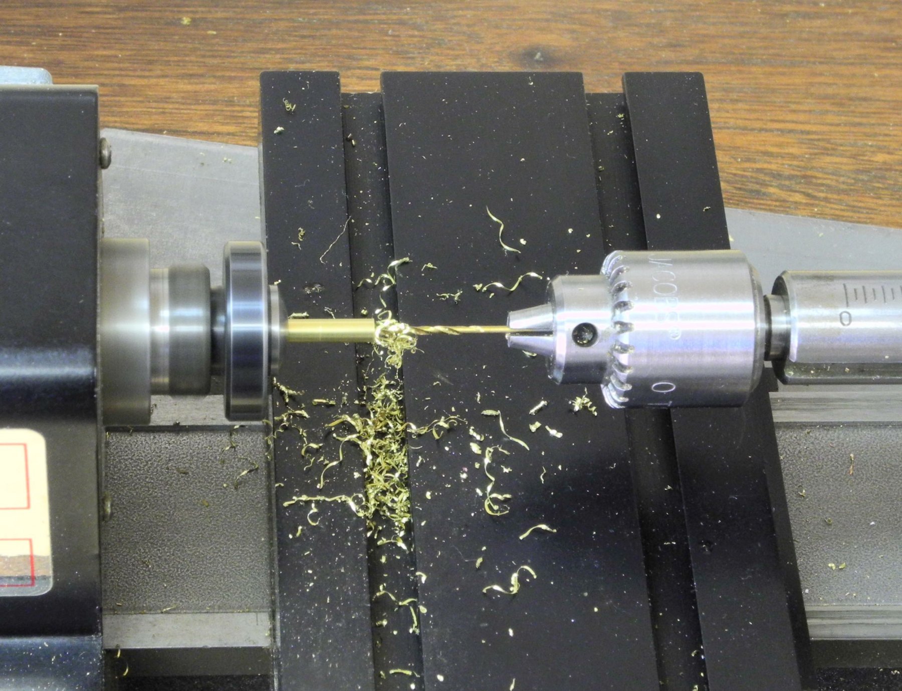
Hi Alan - your question is certainly not dumb. I was going to make a short post to update my block-making, but here are the changes I made: 1. I initially drilled the 'boundary hole' all the way through the block. I found that this produces a groove through the top of the block that needs to be sanded down, thus shortening the length of the block. I decided to instead drill a shallow 'boundary hole'. It needs to be deep enough to identify the boundary, but it can easily be sanded out by rounding the top and bottom of the block (as would normally be done anyway). 2. I decided that a better micro chisel would be to make a chisel using the same size drill as was used for the holes. Using a rotary tool and a diamond cylinder, I grind down the back of the drill to a chisel form. This is mounted in a pin vise and is used for shaping the groove that, after using the small round file, becomes the 'sheave' in the block. Hope this helps.
-
Thanks Dan. I've been making the rest of the blocks, and have refined the process a little.
-
Thanks, Mark. Drilling the 'boundary hole' at the edge of each block is a technique I learned from EdT's build log - one of the many useful techniques I've learned from watching his work.
-
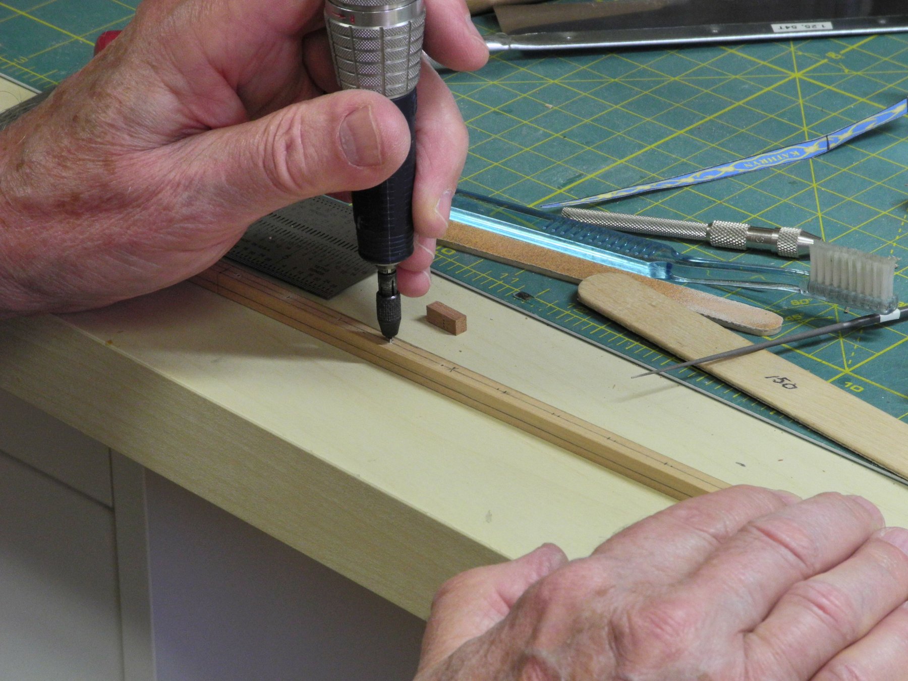
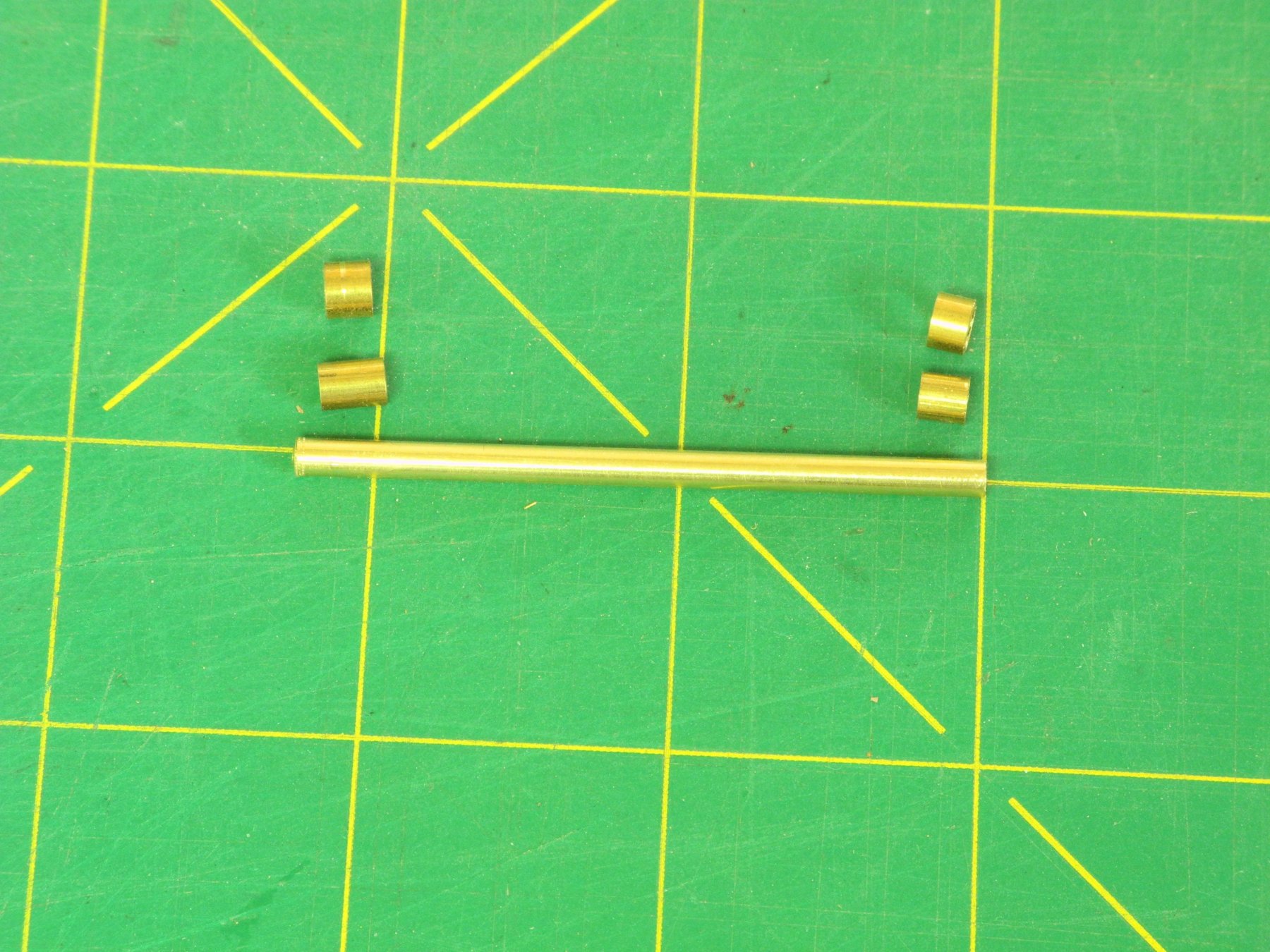
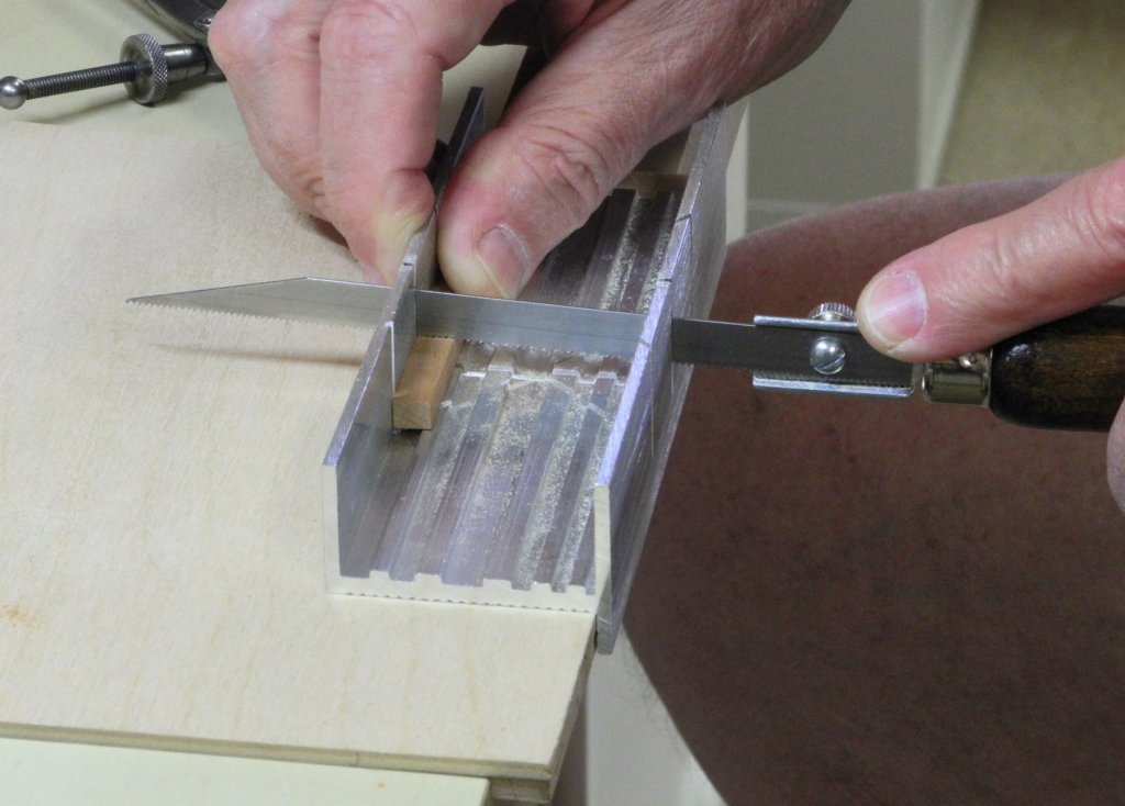
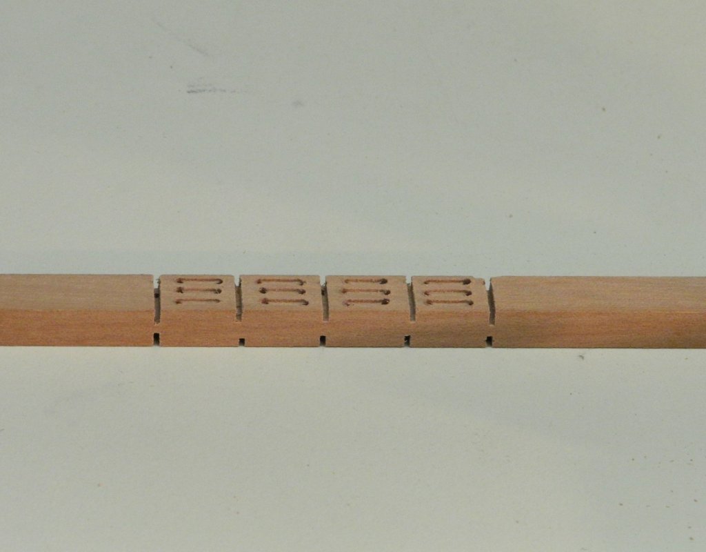
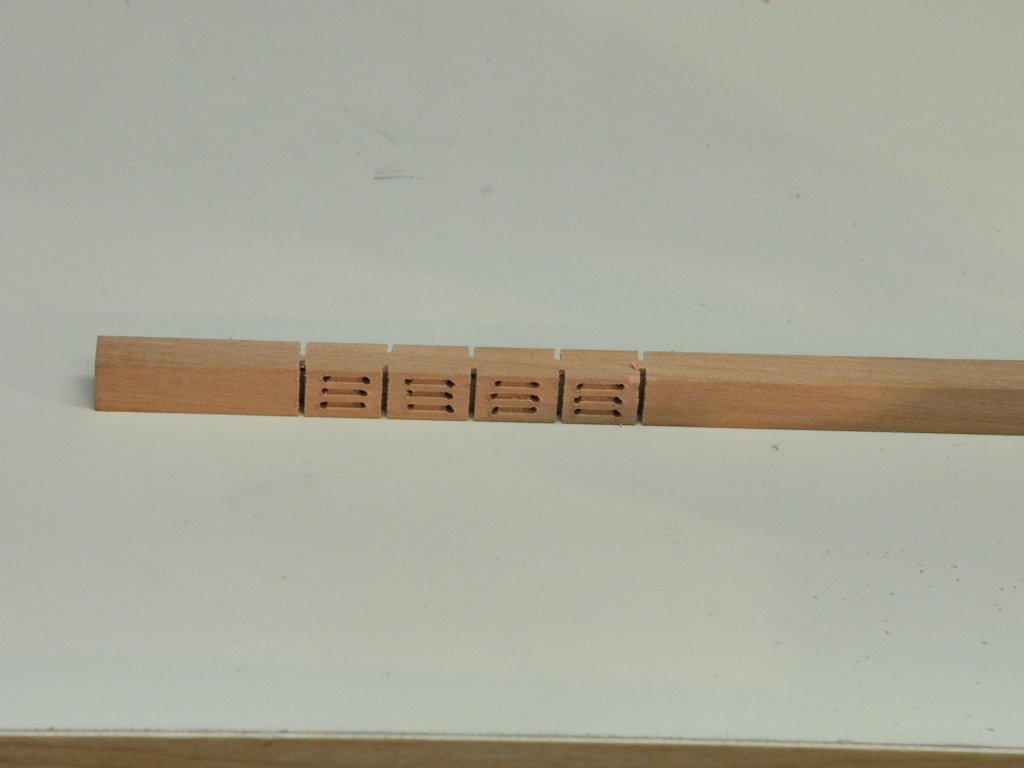
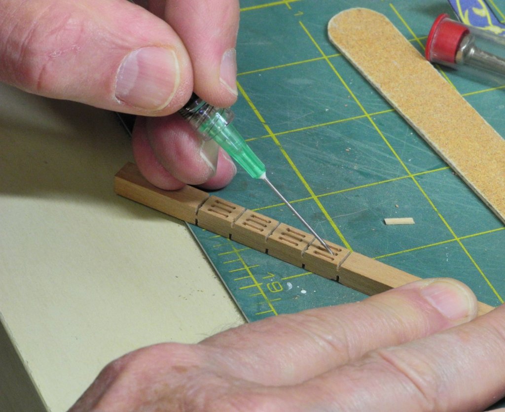
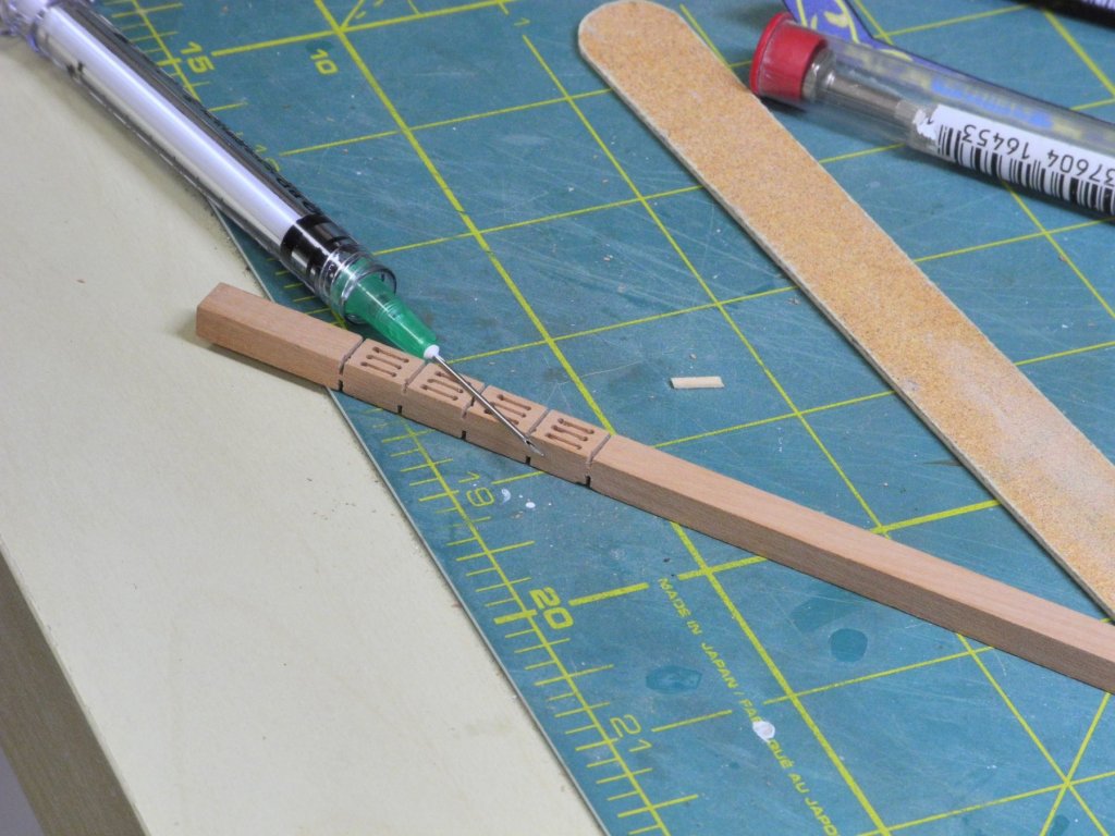
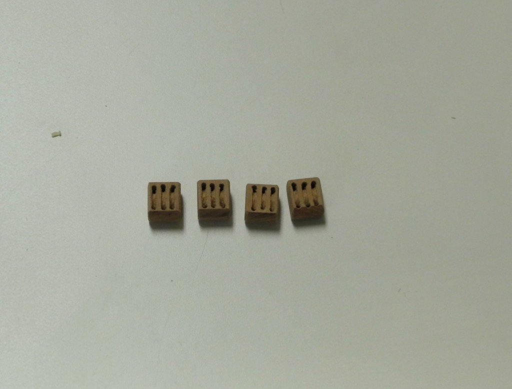
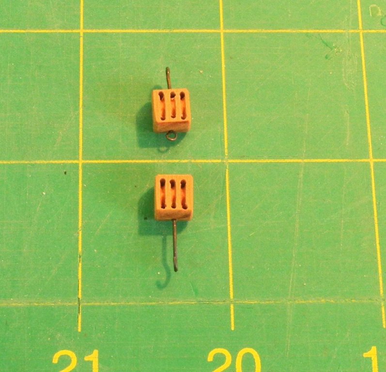
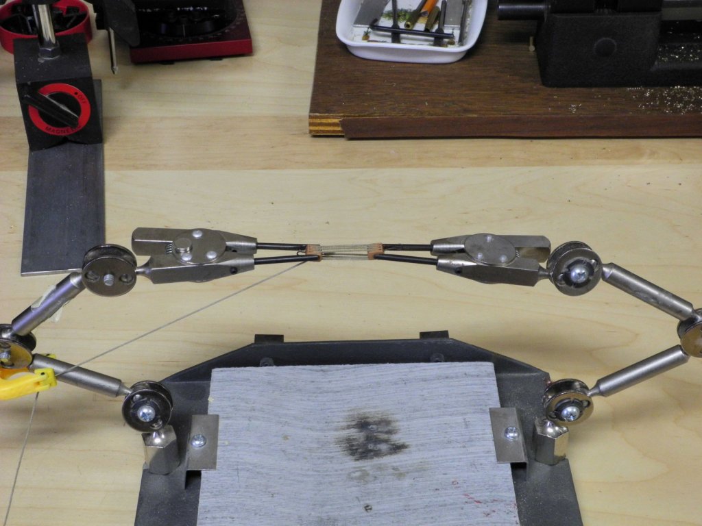
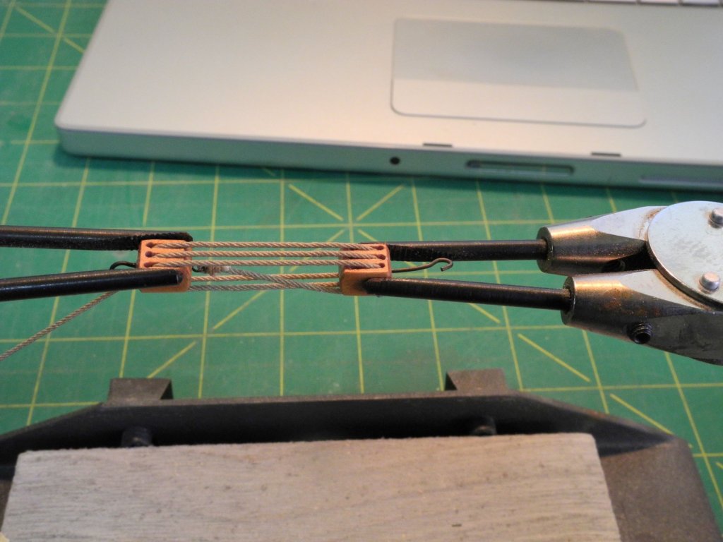
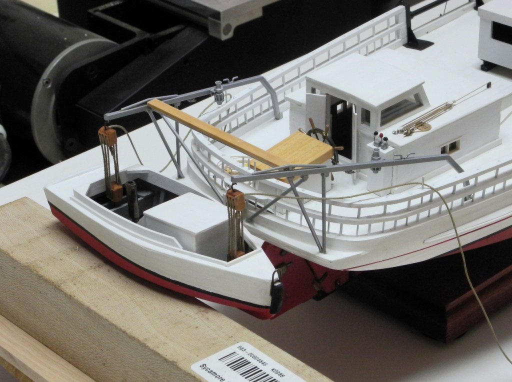
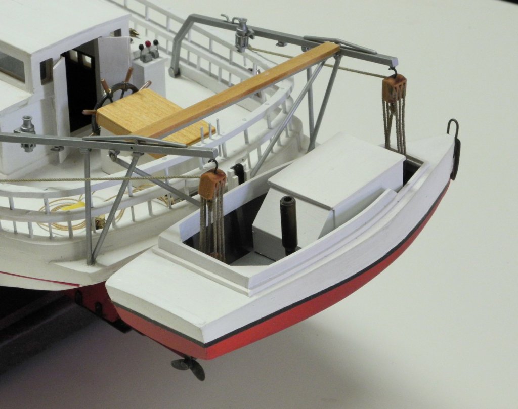
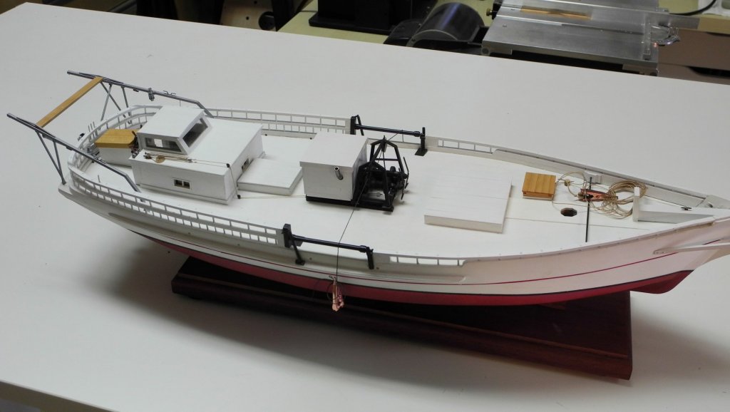
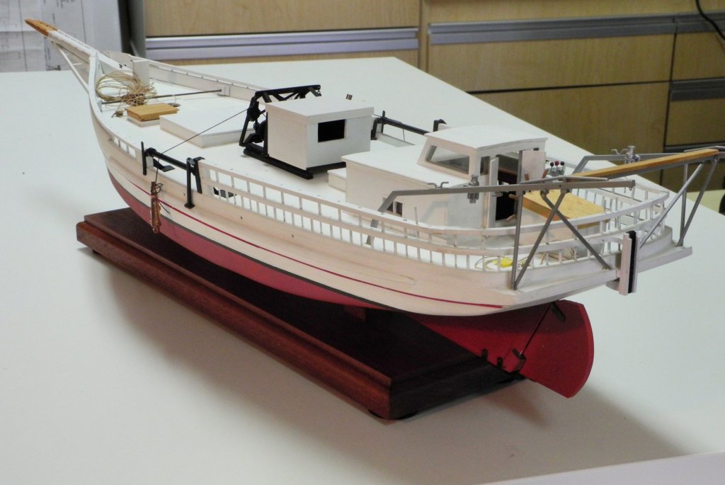
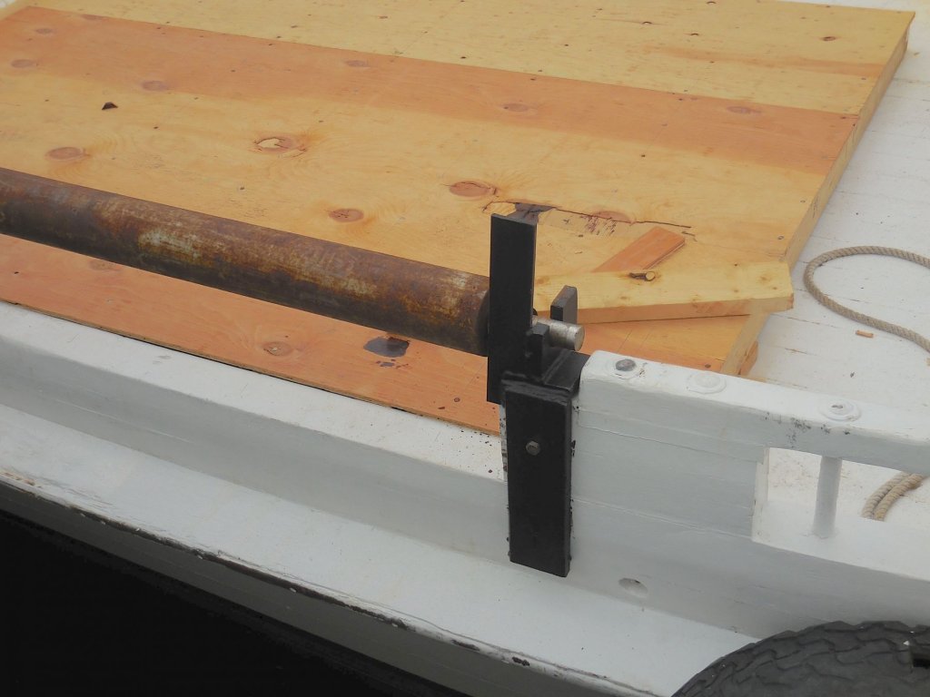
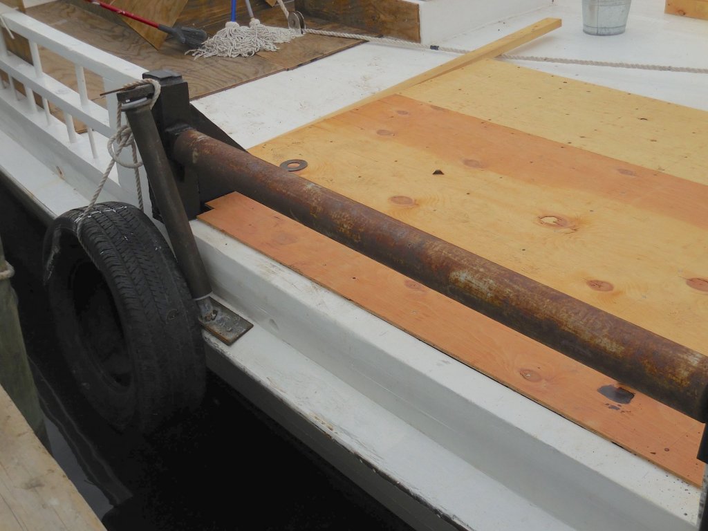
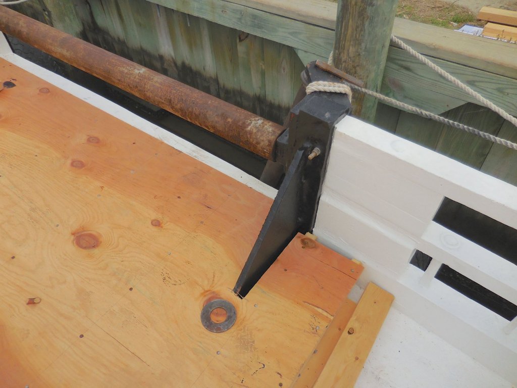
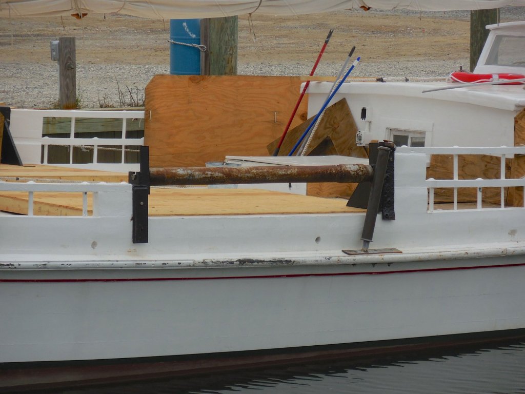
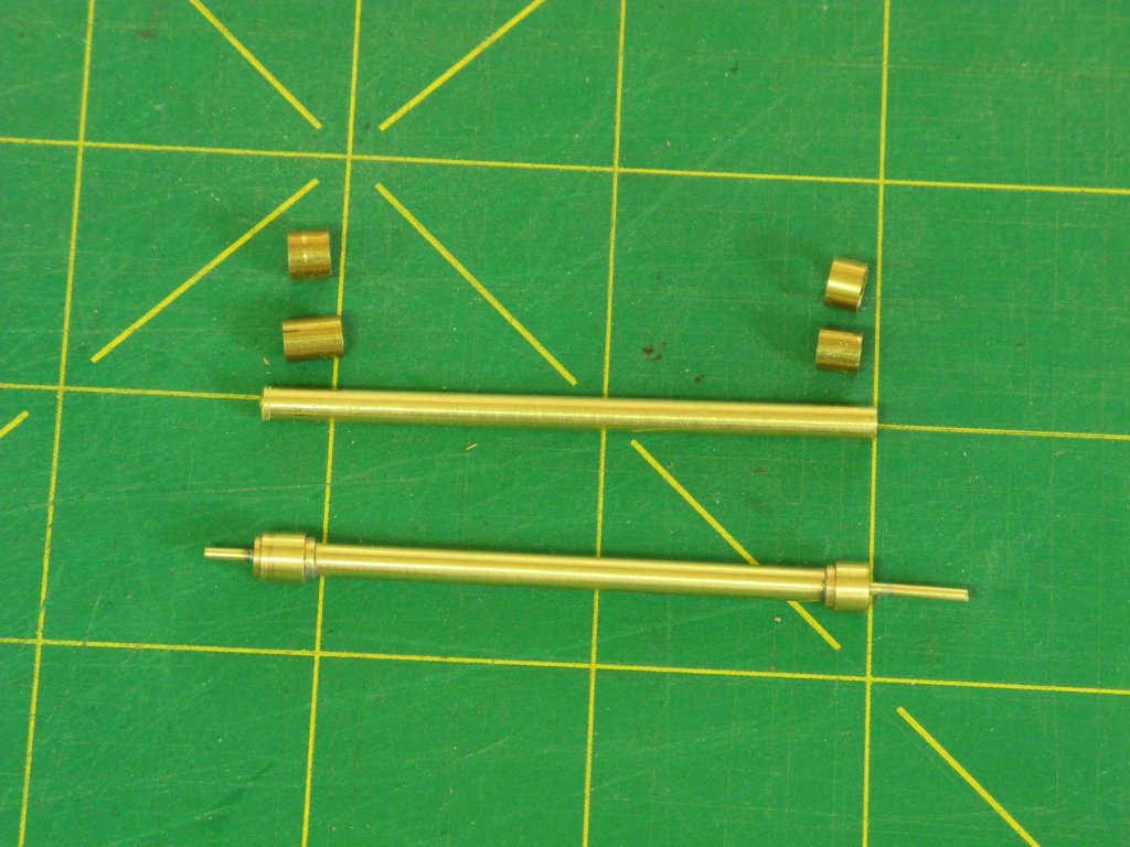
Part 65 – Mounting the Yawl Boat The boom extends beyond the Yawl Boat (Push Boat) when it’s on the davits, so mounting the boat on the davits prior to installing and rigging the boom will probably avoid some risks. The triple blocks holding the 1800 pound Yawl Boat are the largest of Kathryn’s blocks. The measurements from the HAER drawings, and the photos in “Working Skipjacks” showing the crew hauling the Yawl Boat, indicate that the lines are probably 1-inch rope. The blocks actually used on Kathryn are of two different types, shown in the next photo taken at the time of the HAER survey and also in the second photo that was taken last year. Having two different types of triple blocks on the model would look strange, so all four of the blocks for the model will be identical wooden blocks. The stock for the blocks was mounted on the mill, and the sheave holes were drilled, along with single holes to indicate the boundary between two blocks. After all of the holes were drilled, a small end mill was used to cut a groove between each of the top and bottom sheave holes. Using a saw whose kerf is roughly the size of the drilled boundary holes, a partial cut between blocks was made on each side of the workpiece. Rounding the ‘sheave’ will make the rope lay properly, and this rounding was started using a very small ‘chisel’, in this case a sharpened hypodermic needle. Rounding was completed using very thin round escapement files. Hooks were glued into the top of the upper blocks and the bottom of the lower blocks. In the case of the lower blocks an elongated shaft was required due to the tight clearances within the yawl Boat. The upper block also had a ring inserted in the bottom to act as a becket. The weight of the model Yawl Boat isn’t enough to stretch the ropes tight enough, so the blocks were held at the appropriate distance apart, the ropes were stretched tight, and then the ropes were saturated with diluted white glue. The rope was made with a Prosak machine from Domanoff Workshop, using DMC Cordonnet crocheting thread. The rope was dyed using RIT dye, following a formula from N. Roger Cole. A description of how I make rope is contained in page 3 of the build log for Paragon, at the following link: https://modelshipworld.com/index.php?/topic/10788-paragon-a-modified-mayflower-by-mahuna/&page=3 When the Yawl Boat was hung on the davits it was obvious that the boat wasn’t balanced properly, so it needed to be propped up and then the lower aft block was CA glued to a part of the Yawl Boat to keep it level. All of the hooks were secured in place using a small drop of CA glue. There are a small number of blocks required for Kathryn’s rigging – only a few 5-inch single blocks and 2 7-inch double blocks. I’ll try making those blocks next. Thanks everyone!


- 878 replies
-
- 22
-
-
Great start, Doug. I'll definitely be following along. I found the Crothers book to be a great help when I worked on my Dunbrody sectional model. Another very helpful book is "Wooden Ship-Building" by Charles Desmond - I found it on Alibris, and they currently have a few copies available.
- 108 replies
-
- 2
-
-
- leon
- brigantine
- (and 1 more)
-
Sounds good, Rich. I’m traveling at the moment but I’ll try to arrange something when I get back - for a July meeting.
-
Thanks Brian. You haven't seen Kathryn up close in quite a while - we should make plans for you to come over sometime soon.
-
Hi Ron I've already drawn the trailboard in CAD - very much like yours, but thanks for the offer My quandary is whether to carve and paint it, make a decal from it, or paste on a paper version. Time (and some experimenting) will tell.
-
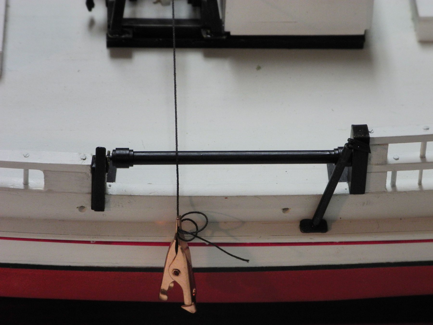
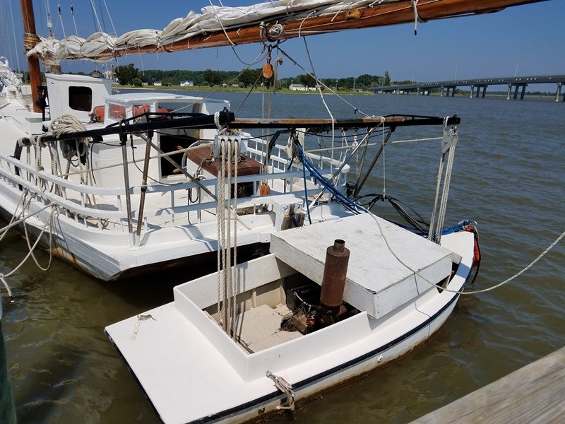
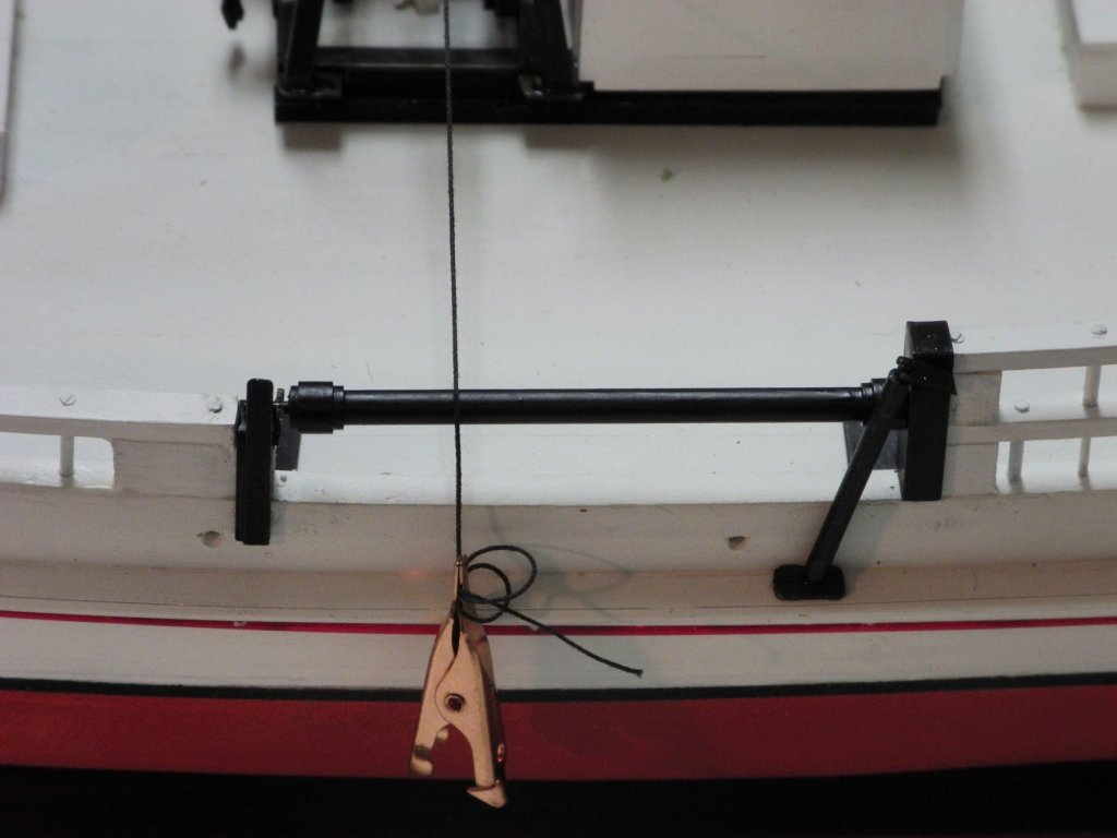
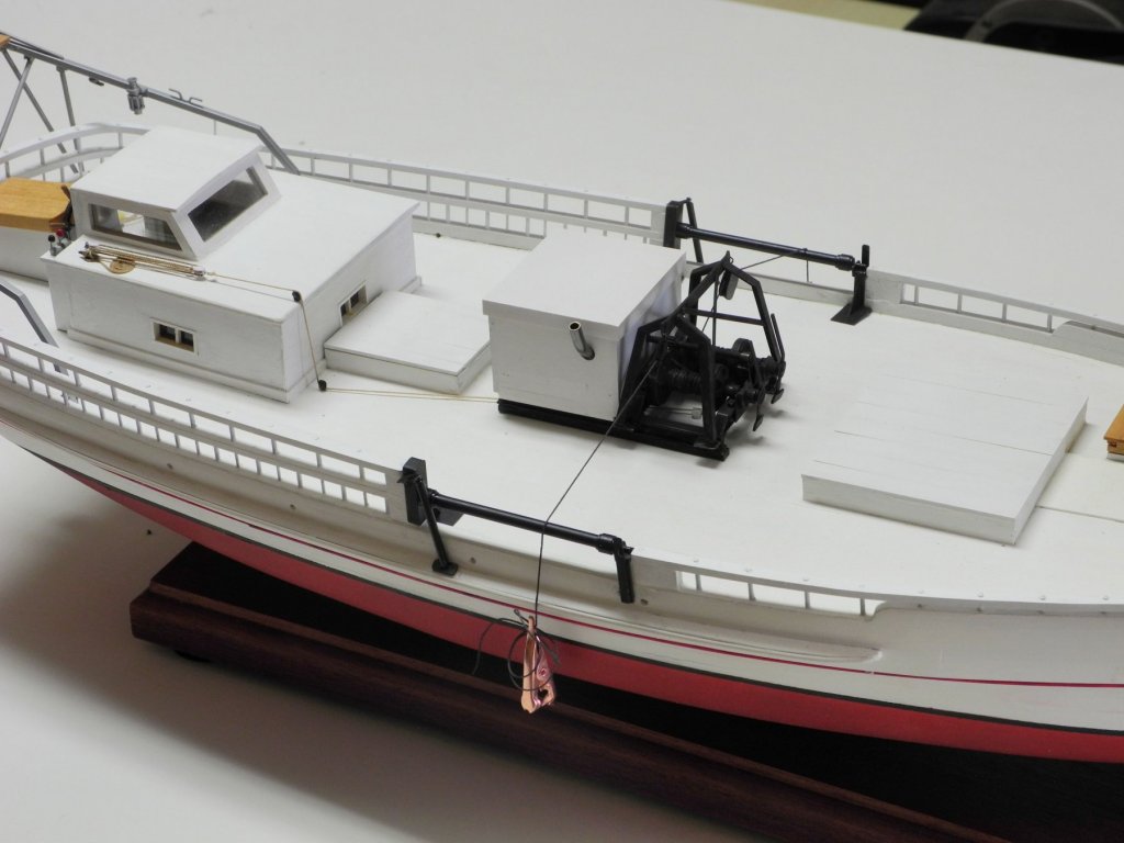
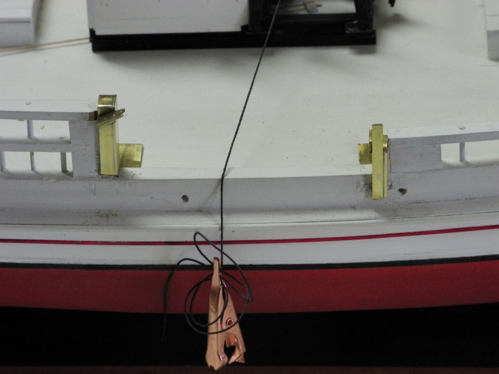
Thanks for all the stars, Peter! Yeah, Jerry, I cringe each time I take a photo with the alligators in it, but they're necessary to keep a little tension on the 'cables' for the dredge (drudge) baskets. You and Jerry brought up the dredge baskets that I've been trying to avoid thinking about for the time being. The frames shouldn't be too much of a problem, but I'm not sure how I'll do the 'netting', which is a combination of metal rings and twine.
-
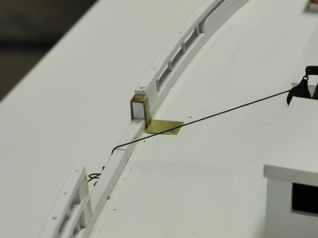
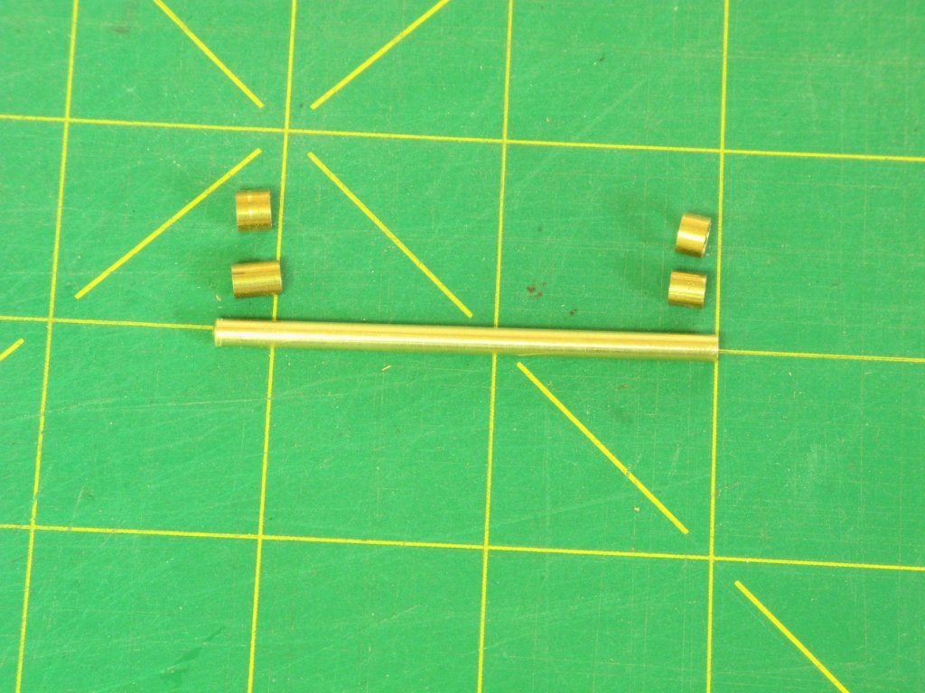
Part 64 – Dredge Rollers cont’d The remaining work on the dredge rollers consisted of blackening all of the dredge roller hardware, and then installing it on Kathryn using epoxy glue. The vertical rollers were made from 2mm brass rod, with an axis made from 3/64” brass rod inserted into each end. The lower axis fits into a corresponding hole drilled into a mounting plate that is installed on the side protective molding, and is shown installed in the following photo. The vertical roller was then epoxied into the mounting plate and to the angled piece on top of the aft support. This completes the installation of the dredge rollers. The major metalwork on Kathryn’s body is now completed. There is still a lot of metalwork required for the rigging. Before any new work is started, there is a lot of planning to do, including developing approaches for the following efforts: Making the detail on the trailboards Manufacturing the blocks required for the rigging Making furled sails Working with wire rigging, including making scale turnbuckles and shackles. So with all of this ahead, and with some trips coming up, there may be some longer intervals between posts. In the meantime, thanks everyone for the likes and comments, and for the continued interest in Kathryn.


- 878 replies
-
- 21
-
-
Hi Patrick - welcome back! It's been a fairly productive short spell for me, and I'm pleased with the results. Hi Joe - thanks for the kind words. It has taken a while but I'm fairly comfortable with metal work now. Skipjacks are beautiful working craft and are a unique part of the American nautical heritage. I'd love to see one of the annual skipjack races.
-
Hi Patrick. All I can say is 'wow!' (as usual). That roof certainly is complicated, but you nailed it.
-
Thanks Albert, Ron, and Jack. The HAER drawings are a great source of detail. In addition I have lots of photos I've taken during my two visits to Kathryn, and I also have some older photos provided by a friend. All of this has been extremely helpful in deciding what to model on Kathryn and how to do it.
-
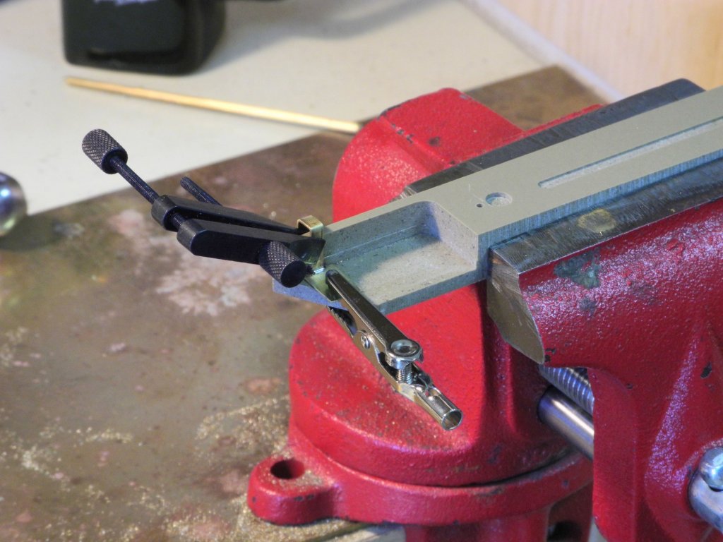
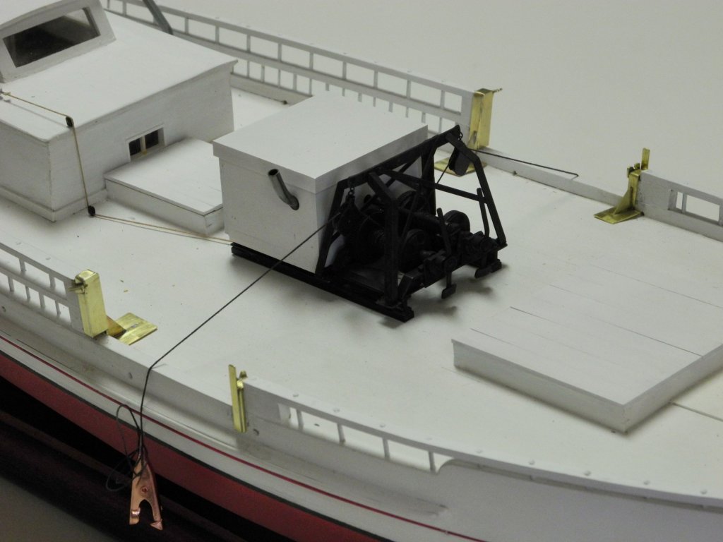
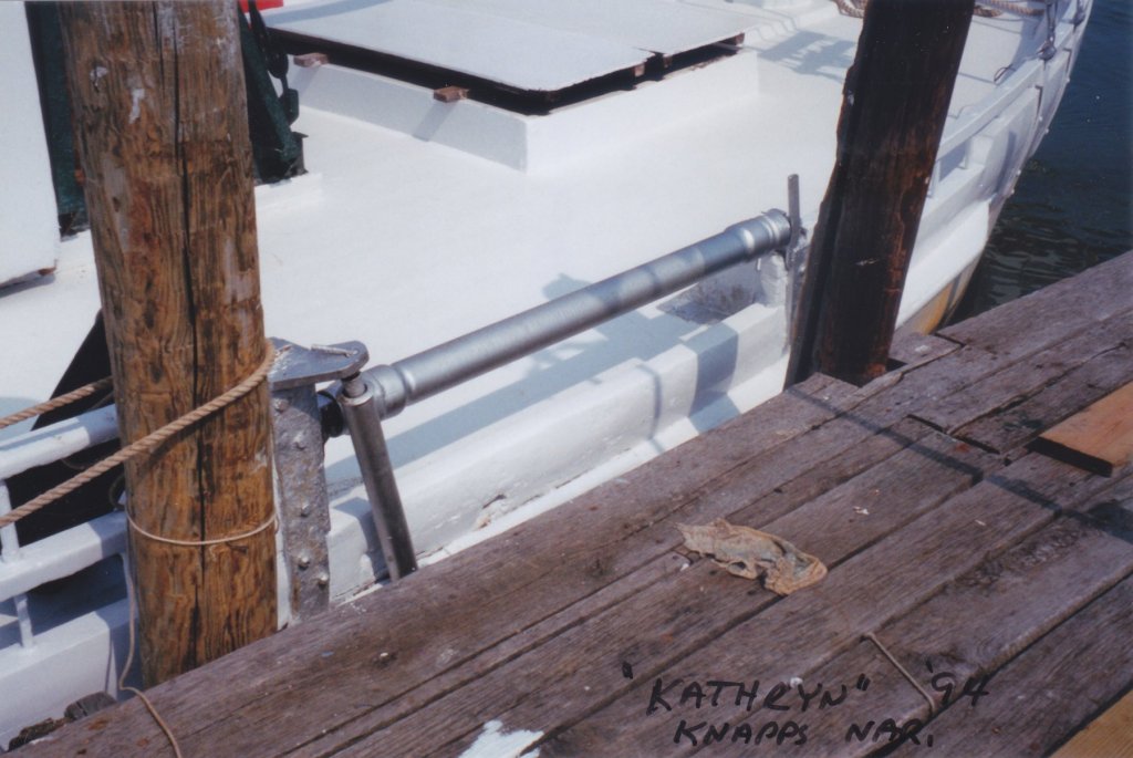
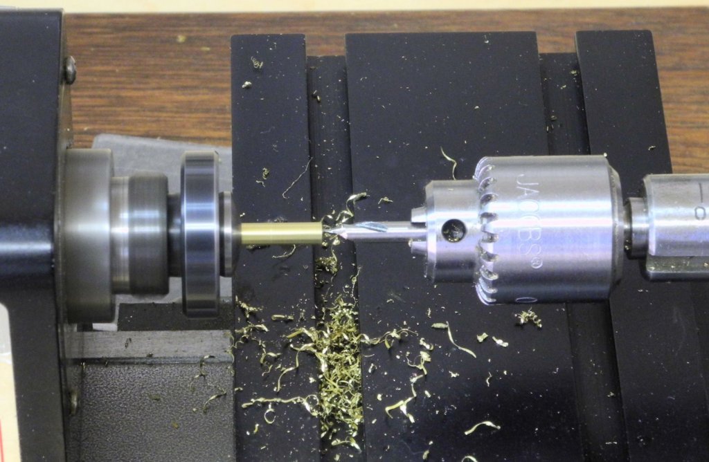
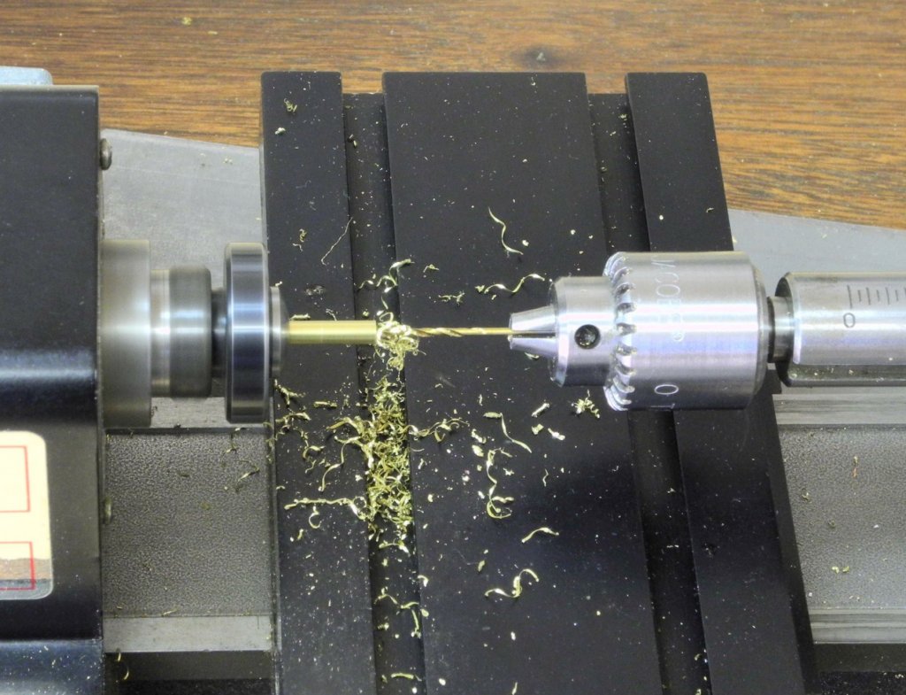
Part 63 – Dredge Rollers Kathryn has dredge rollers that are configured like the typical skipjack’s rollers. The supports for the rollers are fairly complex, and I decided to model them as close as possible to the actual supports. The forward support is constructed so that it wraps around the aft part of the forward railings, and the top of the support is slightly lower than the top of the railing. The axis of the roller fits into a notch in a plate on top of the support, and there is an extended piece that prevents the roller from slipping out of its support. The aft roller encases the entire railing configuration, and the axis of the roller fits into the front of the support. At the top of the aft support there is a slanted piece that supports the vertical roller. Each of the supports has an inboard triangular brace. On the model, the main part, or body, of each support was made the same way – as a single piece folded over to encase the rail. First, an appropriate sized piece of brass strip (1/8” x .025”) was scored where the folds would occur. These scores were used to register a small triangular file that was used to open up the scores. After annealing the strip it was clamped in the vise and bent, then hammered, to make a 90 degree bend. The strip was then clamped to a 5/32” x 1/8” square tube (the width of the rail is 5/32”) and bent and hammered. This corner wound up being slightly rounded – probably unavoidable. The workpiece was then held in a jig made of Corian, and the base was soldered onto the body. The following photo shows the body of the forward support test-fitted to the railing. A small piece of 1/8” x .025” strip was soldered to the top of the forward support body in order to form the vertical piece that the roller axis rests in. Still clamped in the jig, the vertical piece was shaped to fit the contours of the support body, using a rotary tool and files, and the notch in the vertical piece was made using a small round escapement file. The extension for securing the roller was then soldered in place. This completed the forward supports for the dredge rollers. As can be seen in the above photo, the constant test fitting of the support has resulted in some marring and dirtying of the painted surface. This will need to be cleaned up before final installation of the supports. The body of the aft support was made the same way, with the addition of a front plate that was soldered to the body after bending was completed. The triangular inboard support was added to all four of the supports, using the following setup for soldering. The heavy block on top of the ‘third hand’ is to ensure that the piece makes full contact with both the bottom and the vertical surfaces of the support. The angled piece on the aft roller support, for supporting the vertical roller, was made from a piece of brass angle, and was shaped to conform to the support body. The forward and aft supports can be seen in the following photos. The rollers shown in the HAER drawings, and in a photo taken at about the same time as the HAER survey, shows sleeves at both the fore and aft ends of the rollers. Although these sleeves could have been turned on the lathe, it was much simpler to make them out of tubes that would fit over the roller bodies and each other. The roller bodies (1/8” brass rod) were drilled with a center drill and then drilled to take the axis pieces (3/64” brass rod). The rollers were test-fitted to the supports. The sleeves were then soldered to the rollers. The dredge rollers are now ready for blackening, and for the installation of the aft vertical rollers. I love the look of the clean brass, but in keeping with my plan to make the model look as much as possible like the real Kathryn, the brass will be (dis)colored. I feel like I should apologize for this long post and the many photos, but I wanted to show the process as complete as possible. The next post will complete the installation of the dredge rollers.


- 878 replies
-
- 23
-
-
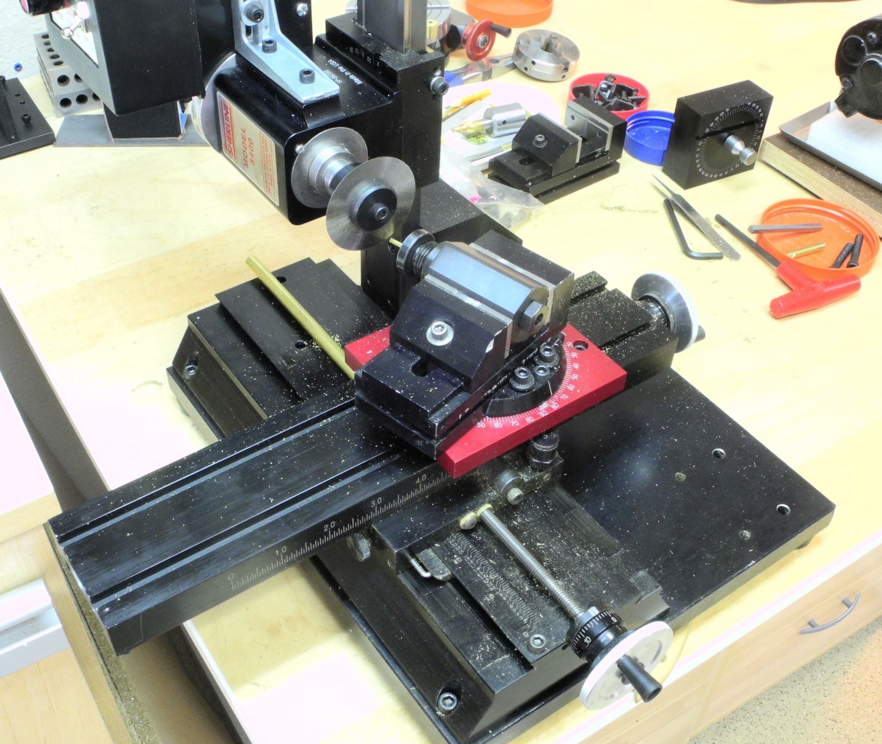
Good question, Tom. The rod was held by a collet mounted in the index block, so essentially this combination was one solid workpiece. I tried aligning the back of the index block with the back side of the vise by eye, but this wasn't very accurate. I wound up holding a parallel bar against the back side of the vise and sliding the index block back until it touched the parallel bar. This gave me the repeatable position of the cut.
-
Thanks Carl. I'm leaving the prop as is. I think the only other look I'd want would be a bronze color. And I would take orders, but I don't think you'd like my hourly rate! Thanks Ron. When I first got the machining setup I was pretty intimidated by it, but now I'm enjoying the challenge. Hi Popeye - thanks for the kind words. You're right about the winch - they don't look like they're in very good shape. I'm pretty sure they're electric - in some of the photos I can see how the electric cables run to them from the batteries.
-
Hi Brian - great to hear from you. Yeah, it sometimes takes much more time to come up with the right setup than it takes to actually execute the milling - but it's worth it!
-
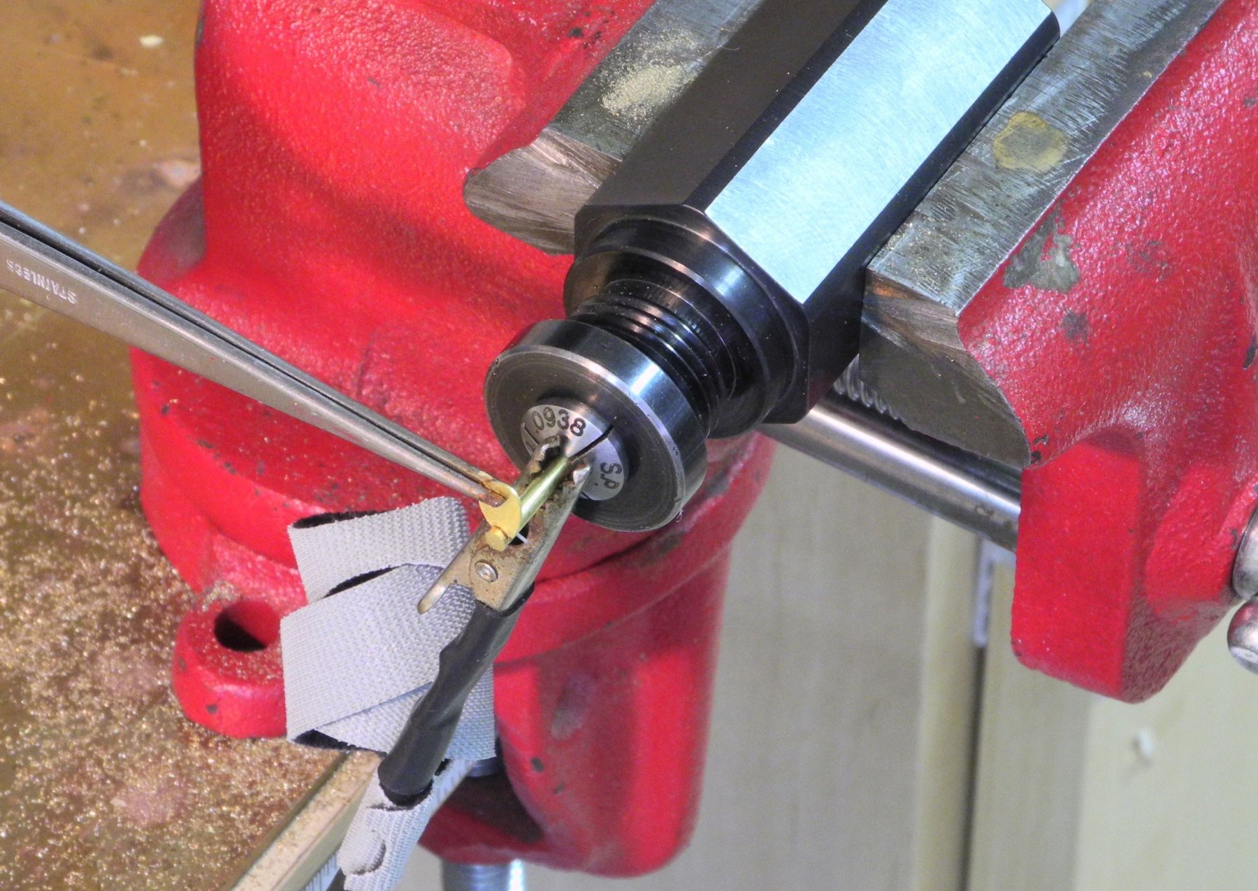
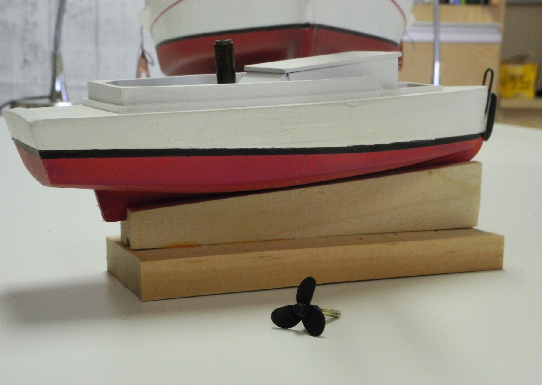
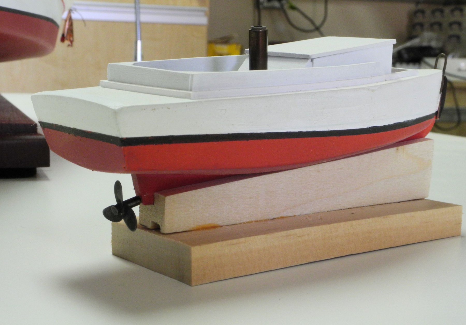
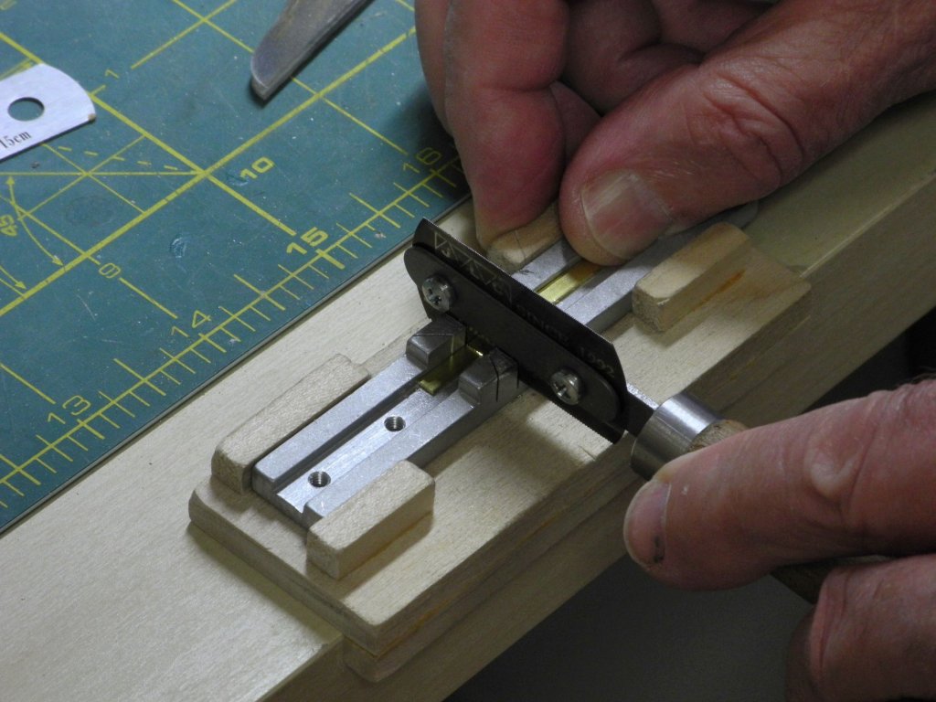
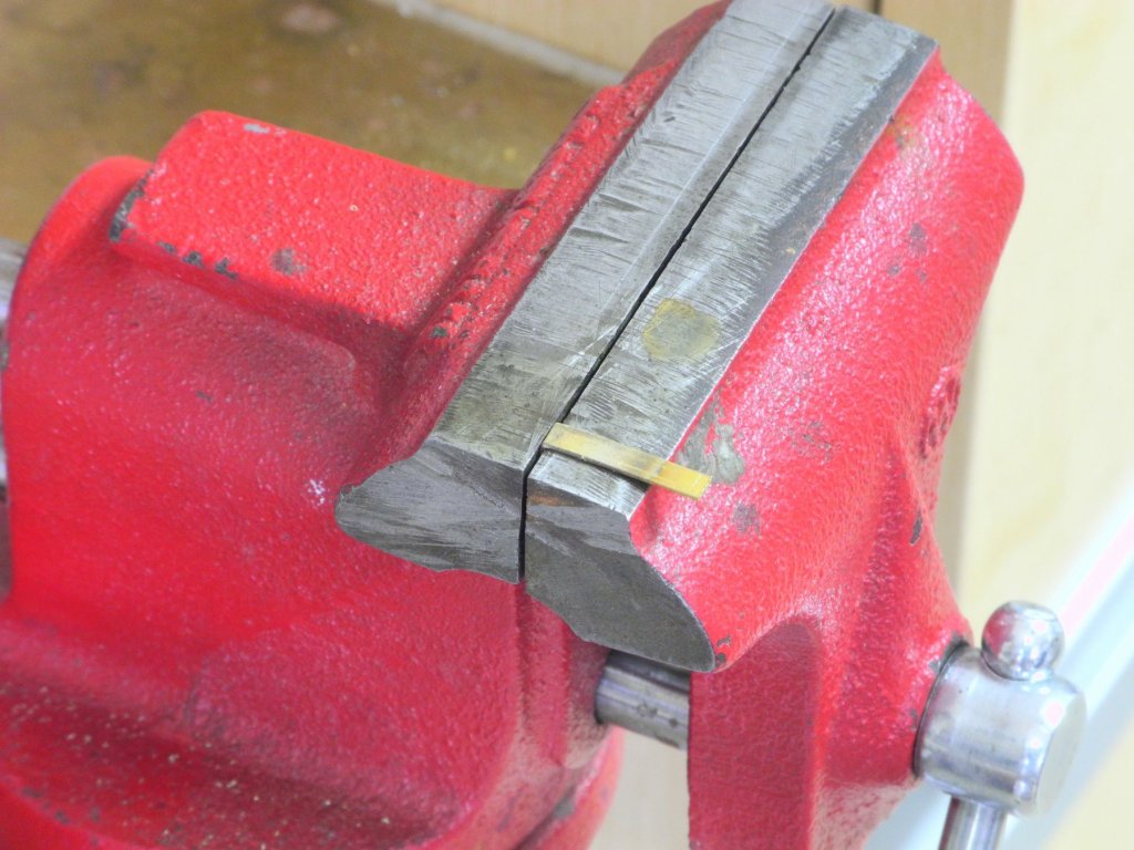
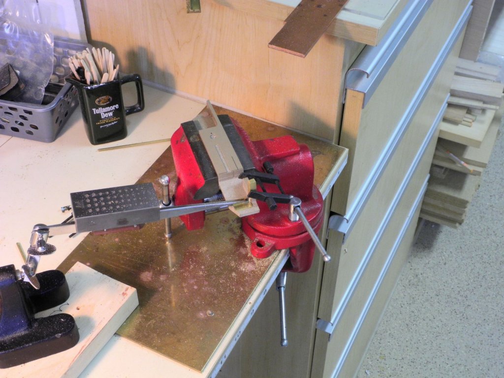
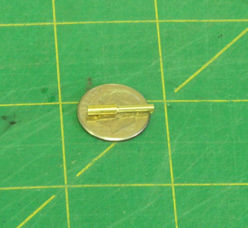
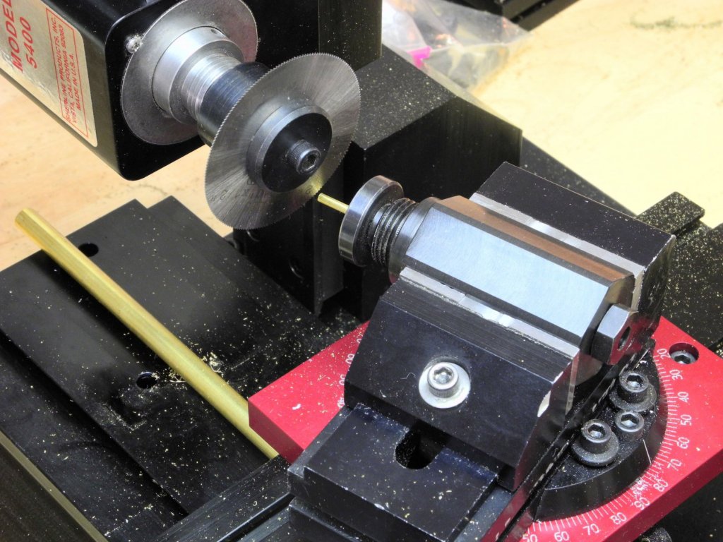
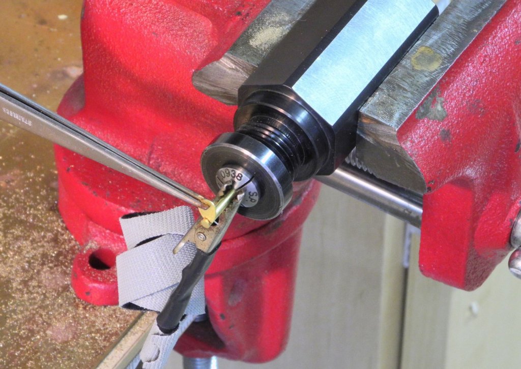
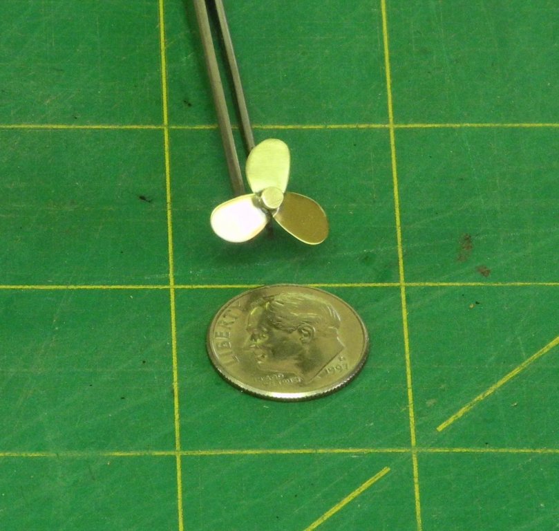
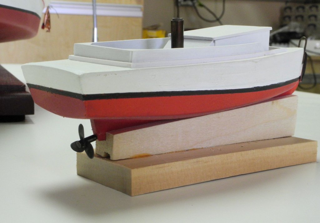
Part 62 – Pushboat Propeller I decided to go ahead and try my luck at making a propeller for the pushboat. An image search on the web gave me lots of choices. After importing a photo of a propeller into CAD I traced the outline of one blade and marked off the position of the blades. 5 small pieces of .010 brass sheet were glued together using Ambroid glue. When the stack cured the drawing of a blade was glued to the stack of brass sheets and the shape of the blade was then cut out using a jewelers saw, followed by final shaping using a rotary tool and files. The stack was then separated into individual blades by a brief bath in acetone. (Sorry, no photos of this process). The shaft of the propeller was made from 3/32” brass rod, with the forward end reduced to 1/16” to fit into the keel. The slots for the blades needed to be cut into the shaft at 120 degree intervals, and at the same time the slots needed to be made at an angle of 24 degrees off center. The 120 degree intervals could be achieved by mounting the shaft in a collet held by a six-sided indexing block mounted on a milling vise, and repositioning the block for each 120 degrees. The 24 degree cut would be made by using a rotating base for the milling vise. The following photo shows this setup. I planned to use a .010 slotting saw sitting vertically and mounted on the mill. When I tilted the mill head to a horizontal position, however, there was not enough clearance under the mill’s head assembly for the mill vise to travel. Fortunately, when I had purchased the used Sherline setup a few years ago, one of the items included in the purchase was something called a Horizontal Milling Conversion (which I never thought I’d need). This allowed me remove the column and the head assembly from the X-Y table, which provided plenty of clearance for the work. For soldering the blades to the shaft, the indexing block assembly was held in a bench vise and soldered using the setup shown in the following photo. The propeller was cleaned and polished. And was then blackened with JAX Brown-Black applied with a brush. After drilling an appropriate hole in the pushboat keel the propeller assembly was glued in place using CA glue. Thanks everyone!


- 878 replies
-
- 14
-