HOLIDAY DONATION DRIVE - SUPPORT MSW - DO YOUR PART TO KEEP THIS GREAT FORUM GOING! (Only 68 donations so far out of 49,000 members - Can we at least get 100? C'mon guys!)
×
alpayed
-
Posts
102 -
Joined
-
Last visited
Content Type
Profiles
Forums
Gallery
Events
Everything posted by alpayed
-
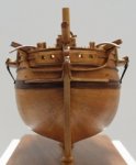
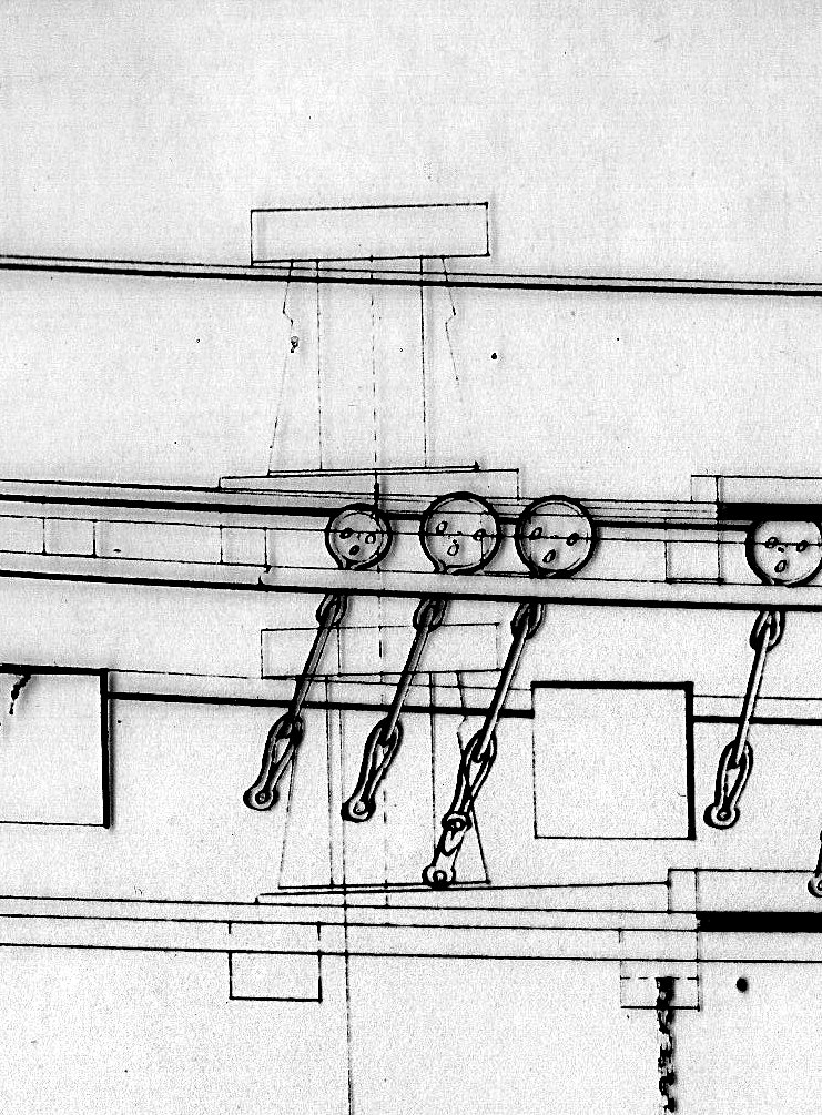
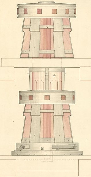
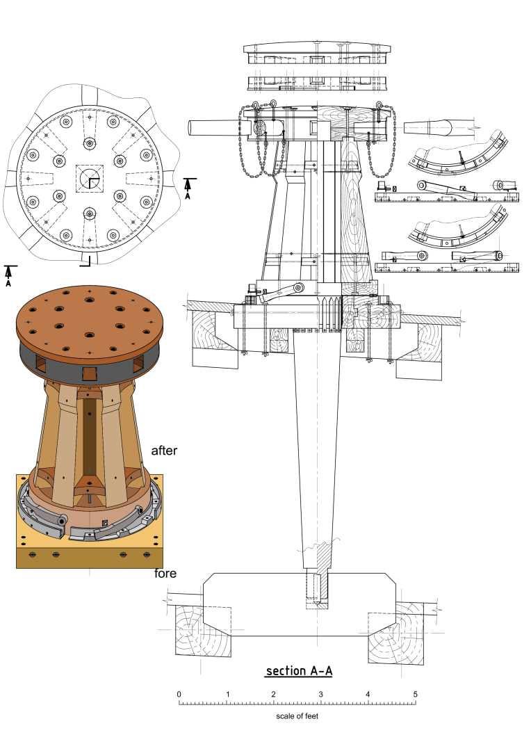
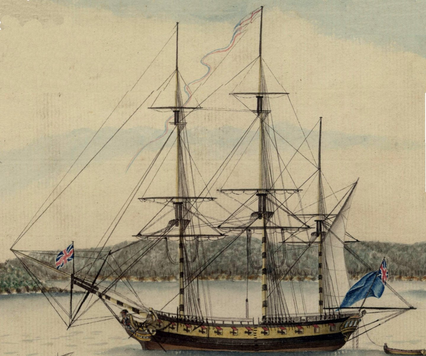
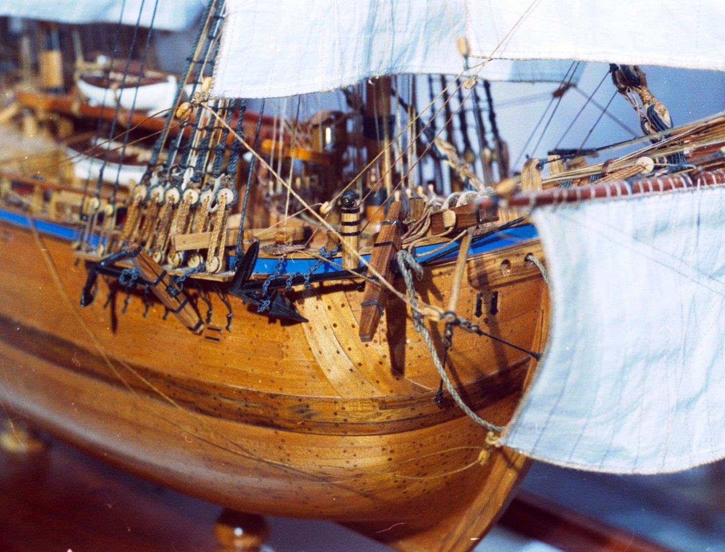
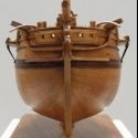 Hi Dave. Sirius had a capstan on both decks (same shaft). Unlike the capstan in my drawing. It probably had the pawls on the lower section. See pic. The pawls on your model need to be moved up so they drop into the ratchet more and probably on the lower section. I am not sure why the ratchet is not shown on the "Berwick" draught Note that they flip over 180deg to allow rotation in either direction. Here also is G Rapers watercolour of Sirius. there is a lot of detail in it. Also a rigging plan that may be helpful. Regards Allan. Allan
-
That looks really nice Bill. The furled sails add enormously to the model. Great job. I look forward to seeing your next build. Regards Allan.
-
One of the advantages of laying planks over each other at slightly different angles is an inherent increase in strength. The joints do not coincide reducing the chances cracks occurring. In later shipbuilding techniques it was called diagonal planking although the planks were almost at 90deg to each other. Regards Allan.
-
Most kits use 2 layers of planking. On the first layer starting with a plank above and 1 below locates and frames the ports accurately. The second layer is then started at the wales. As you work upwards from there the planks can be easily trimmed around the ports defined by the first layer. I have built a lot of models using this method and it really makes things easier but you must accurately locate the wales on the second layer. However it is no more difficult than starting with the wales in the first place. Regards Allan.
-
The outer gammoning is correct. The ships in the pics above are mostly merchant vessels.
-
Hi Steve. Yes I think they show that on small vessels boomkins could have only one or in some cases no guys. There are other pictures that don't have boomkins but they seem to be vessel's with the foremast further aft as Harland mentioned. Anyhow it's always fruitful when there is good discussion on these things. Thanks for everyone's contributions and apologies to Bill for hijacking his post. Back to you Biil. Let's know what you do. Rest assured which ever way you go it would be a brave person to question your decision. Regards Allan
-
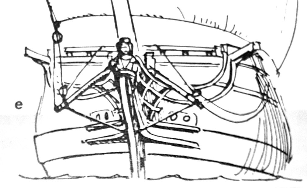
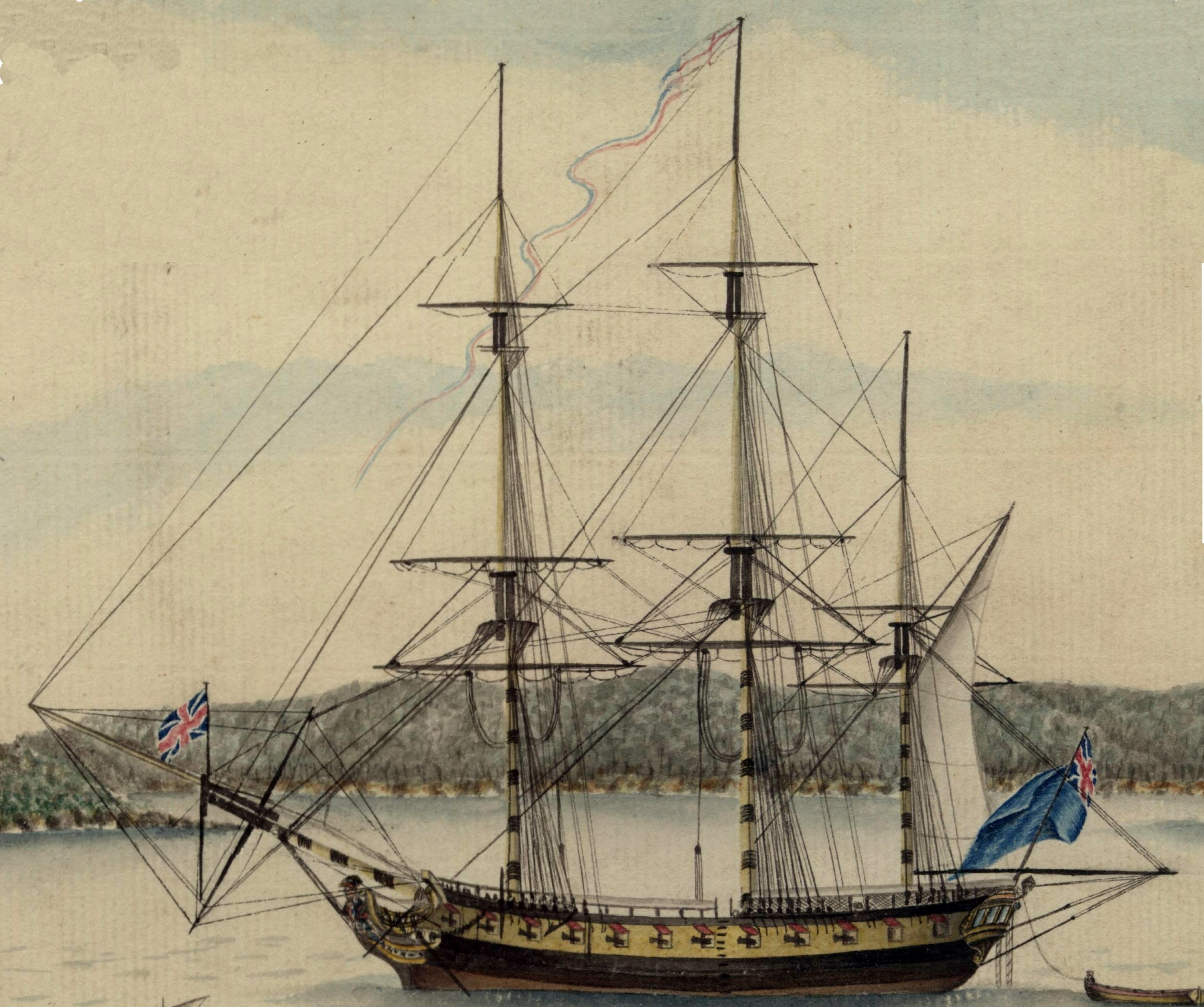
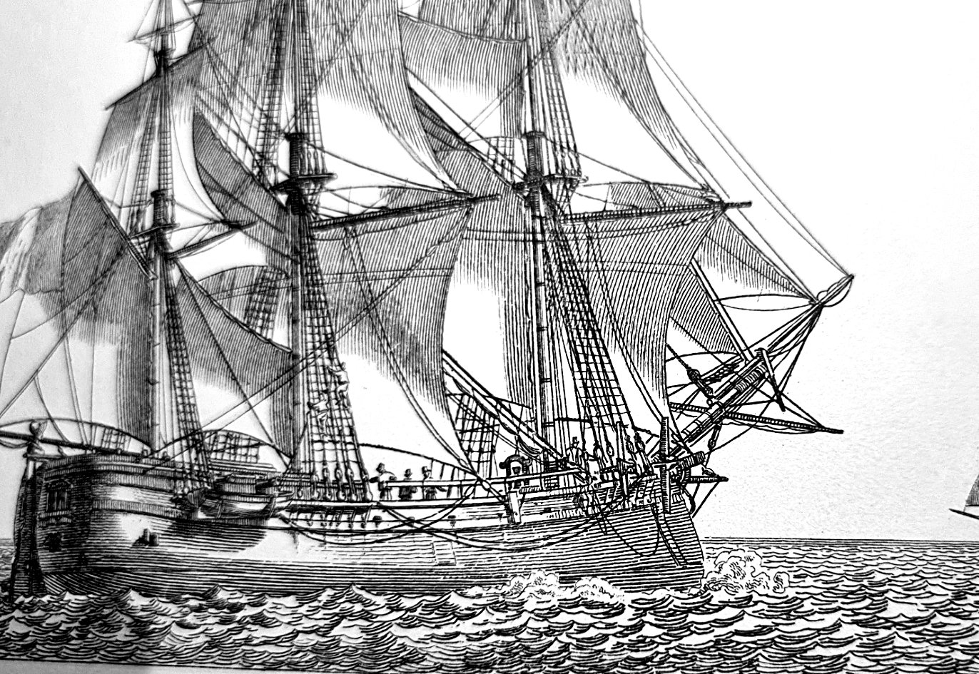
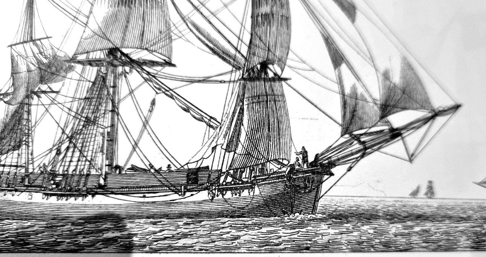
Don't be sorry Steve. We will not advance our knowledge without discussion. Yes I did Steve. There may be only 1 guy. Harland says that guys were often fitted. Often means not always. He then shows a larger vessel with a head with only 1 guy. A small ship may only have 1 guy or non at all. It is a simple method to just move the guy to the stem piece. Harland goes on: Bumpkins dropped out of use in the late 1800s, the tack being got down to the cathead, or some other suitable point. The change was related to the concomitant shift of the foremast further aft, relative to the hull. Tacks rove double (that is to say leading through a block at the clew) only came into use late in the 1700s (Lees, 159). Before that time, a tackle was used to get the tack down, hence the term guff tackle', still in use today. The tack was not led to the cat head until late 1800's Here is what I was saying. Tack leading to the boomkin braced with a single guy to the stem piece. This pic is a good reason not to dismiss a contemporary painting. George Raper. First fleet artist. Armed Tender Supply Main brace boomkins. Not shown anywhere else. Notice there does not seem to be any guys. These artists did not draw fantasy. We have to try to understand what they were depicting not just dismiss it. What was Parkinson trying to show?? I have no other explanation. but whatever they are the were there. Karl was the first person to research Endeavour in detail and propose the boomkins on Endeavour. I have to say I think Karl's boomkins are NQR. That pains me a bit as he was one of my mentors and a great friend. I think he was largely infallible. Ray Parkin also has en excellent volume on Endeavour but has a different idea on Parkinson's sketch. I had a few discussions with Ray also but we could never agree on the boomkin theory. Never mind hopefully time will tell. Regards Allan
.thumb.png.43335e3ee5ac3b672ad40e3d427a7f52.png)
-
Hi Guys. Parkinson drew "something" in that sketch. It is a matter of interpretation as to what they are. If they are not bumpkins or boomkins then the question remains what are they. Until there is a better explanation one can safely assume that the are boomkins. This quote from Harland suggests why Karl put his boomkins at a steep angle from the centreline. On ships with a head they could be on a large angle, but probably more like 30deg. Keeping in mind that Endeavour was a relatively small ship, Harland states "hold-downs were often fitted" inferring that guys were not always fitted. The lower guy could probably be removed altogether hence solving that issue with fouling the cables. From Harland About 1710 or so, English ships began to fit 'tack bumpkins', and these remained in use until the later 1800s. They were sturdy timbers, often exhibiting a slight downward curve, which projected out over the headrail of the beakhead, at an angle of forty-five degrees from the centreline. French ships of the Napoleonic era carried the tack bumpkin at a sharper angle to the midline than their English contemporaries, the intention being to make them more weatherly. When taken into the English service, captured vessels had their bumpkins altered, because it was felt they then tacked more readily than before, the foresail taking aback quicker than when rigged in the French fashion (Griffiths, 180). Because of the tremendous upward pull of the tack, hold-downs were often fitted. On a ship with a head the 2 guys can be fitted exactly as Steel suggests. BOOMKIN-SHROUDS, to support the boomkins, have their after ends hooked to eye-bolts, one above the cheeks of the head, the other in the cutwater: Once again remember Steel is referring to ships in general and on smaller ships the guys may not have been required. Endeavour's fore sail was not particularly large. Harland only shows 1 guy in his drawing of a boomkin going to the cutwater fairly high up. Regards Allan
-
Well done Bill. I think you could move the fish davit next to the boomkin with it resting on the bulwark and lash it there. Regards Allan
-
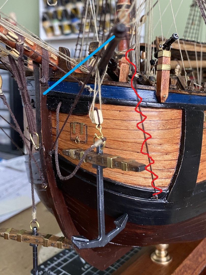
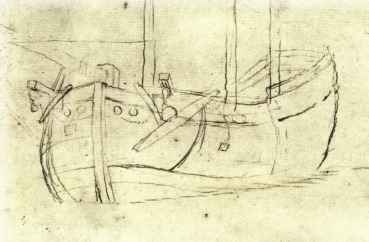
Hi Guys. Going back a few years now so I have to go digging for info. My memory is not what it used to be. Bill here is what I would do. Move the boomkin shroud over to the blue line. This is about how Steel describes them. The existing one to the cutwater and the blue to above the head knees. (which is about where the would be is Endeavour had them) Unless you can swing the boomkin slightly to the bowsprit leave well enough alone. Redo the cat falls to be behind the boomkin This is my drawing of Endeavour from the 1990's Obviously I had a different idea to Karl at the time. I am going to stick my head out now and say that Karl is wrong here. It would not be practical to be removing and replacing guys every time an anchor is used. This is arrangement for Investigator. Finally here is Parkinson's sketch of the bow of Endeavour. The boomkins are clearly forward of the cathead. Regards Allan
-
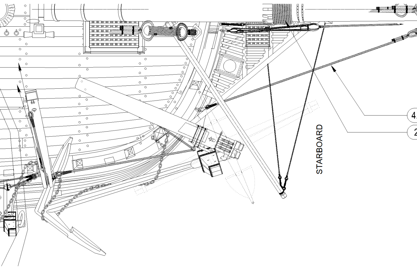
Hi Guys. The Boomkins were for the fore tacks. Any force on them would be to the aft and slightly upwards. I looked at this issue when I was looking the anchor catting/fishing on Investigator. On Investigator I have kept them to the cutwater/stem. I may move one down lower. I also remember it on Endeavour. This model was built in the late 90's so I only have scans of photos. Note also where I put the fish davit. I suppose there must have been some way of raising the other anchors also hinting that they may have been moved about.???? I rigged the model after Karl published the book. Look at the photos in Karl's book. You will see I put the boomkin stays close to the stem. From Steel: BOOMKIN-SHROUDS, to support the boomkins, have their after ends hooked to eye-bolts, one above the cheeks of the head, the other in the cutwater: I think Karl has them a bit too far out in his drawings. Hope this helps. Regards Allan.


-
Hi Trevor, sorry you felt you needed to defend yourself. It was not intending to offend just adding to the discussion. Hi Bill. Trevor may be right. there could be 2 fish davits, 1 each side. Harland states that the earlier type is manhandled side to side and then talks about the shorter one. (easily confused) The stowage of the smaller latter type is a grey area. given that is secured to the deck in an iron "shoe" (Harland) as Karl depicts. Maybe it was stood vertically and secured using the topping lift, (probable) or maybe over the side permanently. (unlikely) Or the shoe could be a loose fit and they were removed and stowed elsewhere. My guess is as good as another's unless some evidence turns up later. Harland also details where the anchors were stowed. Flinders records dropping 2,3 and sometimes 4 anchors at various places on his circumnavigation. These must have been ready to drop quickly at these times. This is the details of Investigators anchors: Anchor stowage (A) Best Bower. starboard, secured with shank painters to the timber heads with the fluke on gunwale. and to the cat heads with stoppers. (B) Small bower. port similar to best bower (C) spare anchor, carried port and fixed to the fore part of the fore channel. (F) Sheet anchor. starboard and fixed to the fore part of the fore channel. (H) Kedge starboard and fixed to the aft part of the fore channel. (D,E,G,I ) Stored in hold Stream and Kedge anchors The spare stream and kedge anchors were stowed below. The sheet anchor (starboard) and spare anchor (port) were stowed at the after ends of the fore channels with the stream and kedge anchors on the spare anchor or down below. Regards Allan
.png.1d2c77ee6b976f3cfac6e1cd48eecfcf.png)
-
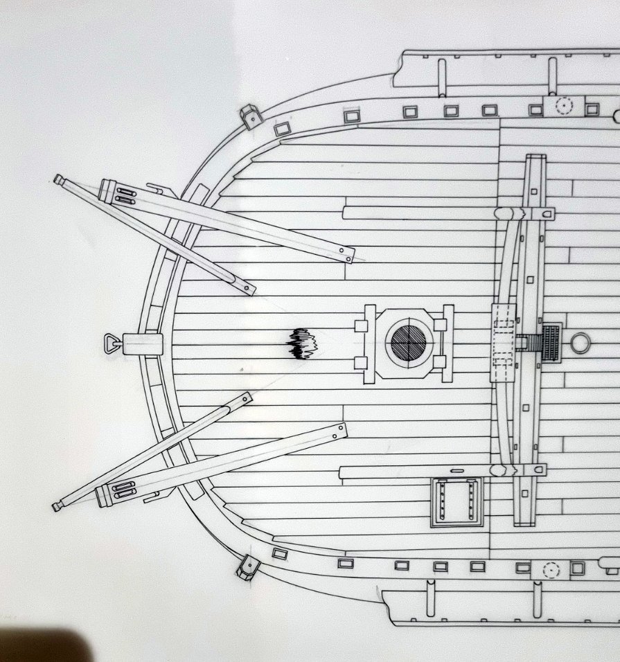
Hi guys. On a collier like Endeavour the anchors were carried as shown here. Best bower and second bower were catted and stowed as shown. I have not shown the shank painter or the securing of the sheet and kedge anchors stored on the fore channels. She would have carried spare anchors in the hold. The fish davit was moved from place to place and probably stored in the channels when not used.

-
This may helpanchor stowage_1.pdfanchor stowage_1.pdfanchor stowage_2.pdfanchor stowage_4-1.pdf
-
In Mathew Flinders diary he states "carpenters making arches fo the ports". I interpret that as being arched gutters to direct water to the sides. (HMS Investigator) Others have interpreted it differently. Has anyone heard of rigols being referred to as arches? Regards Allan.
-
That's an interesting question. I guess the purpose of the model is to display all of the details of the ship in question. Mission accomplished. To show actual function you would need to build a dioarma. They are an entirely different type of model. You have produced a model featuring all of the details of the Endeavour and done really good job of it. It's time to sit back and enjoy the feeling of achievement. Well done. Kind regards Allan.
-
The word lift can be a bit misleading. The halyards did the lifting. The lifts were there to hold the yard level when sailing. one side would not usually have tension on it. The side with tension would normally be the side of the yard rotated forward. (close hauled) In this case it would then be clear of the shroud. the other side being slack. They were mainly to take the weight of the yard when lowered. Harland notes that the lee lift (the one pointing backwards) rubbed on the foremost shroud and caused chaffing. This is probably why a few years later the lifts were shifted to eye bolts on the fore part of the cap. Although Lees states after 1805 I think the practice of using eye bolts in the cap probably occurred on some ships long before it became common practice. On a ship like Endeavour there would not have been lifts on the topgallant yards. The sail was often bent to the yard on deck before sending aloft. Regards Allan
-
Hi Guys. It was vary rare to have a sail bent to the crossjack yard so it was never raised or lowered. The crossjack yard did not carry Jeers. Only slings. It would appear that the Crossjack yard used a Jeer block for the slings. It simply took the weight of the yard. The Endeavour was right in the time of changes to the slings. AOTS book is correct for that time. Just after this period the sling was similar to the fore and main slings without the block. In this period there was a change in the lifts also. (Lees says 1805) Instead of having a span around the cap it was attached to eye bolts closer to the fore part of the cap. Endeavour probably had a span around the cap. Keep in mind that the weight of the yard was taken mostly by the sling. The lifts were used to trim either end of the yard up. When close hauled the end needing to be lifted (because it is being pulled downwards by the brace, weather leech and tack) and is forward and the lift pendent would clear the shrouds. The other end (touching the shroud) would be slack. Hope this helps. Regards Allan
-
In future I shall not try to help when someone asks a question. Regards Allan.
-
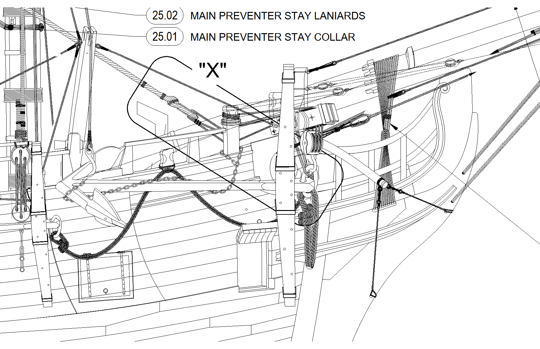
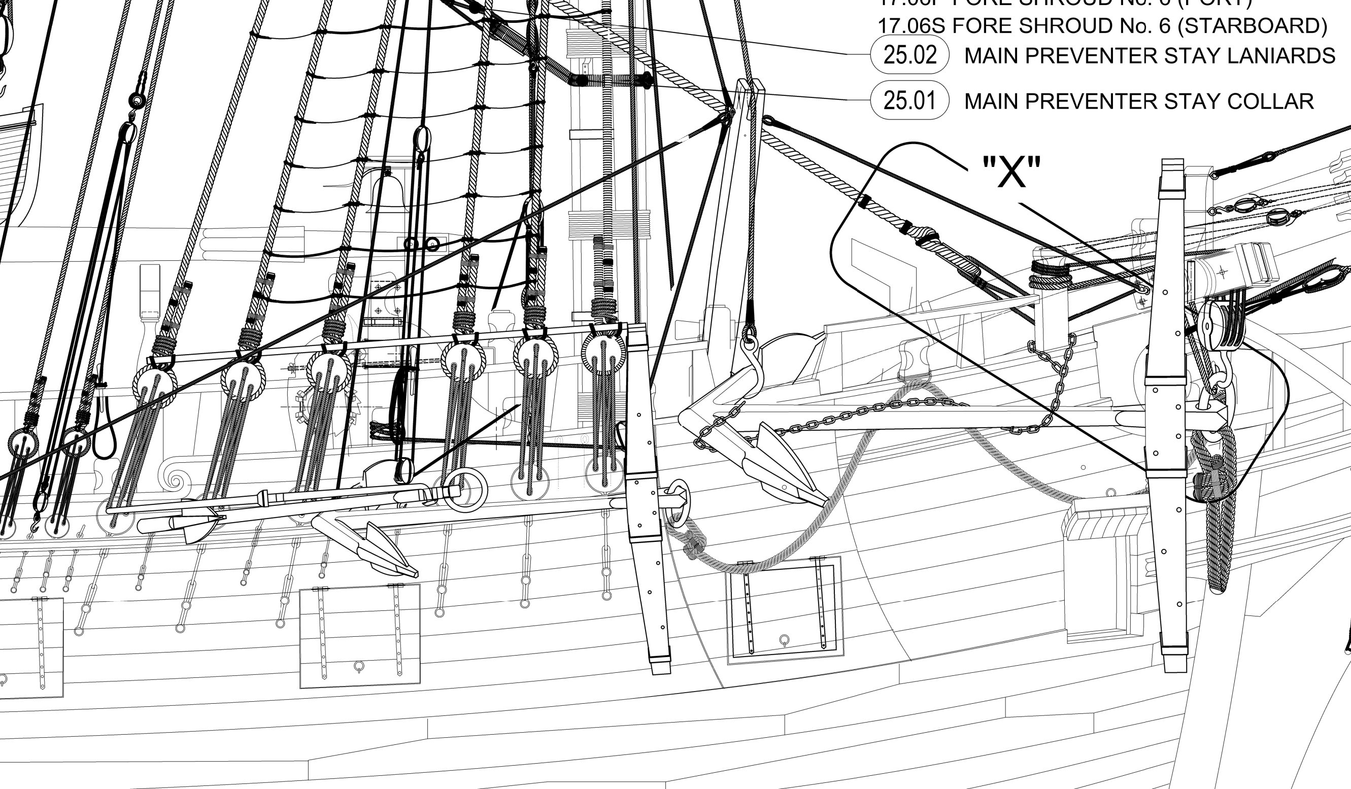
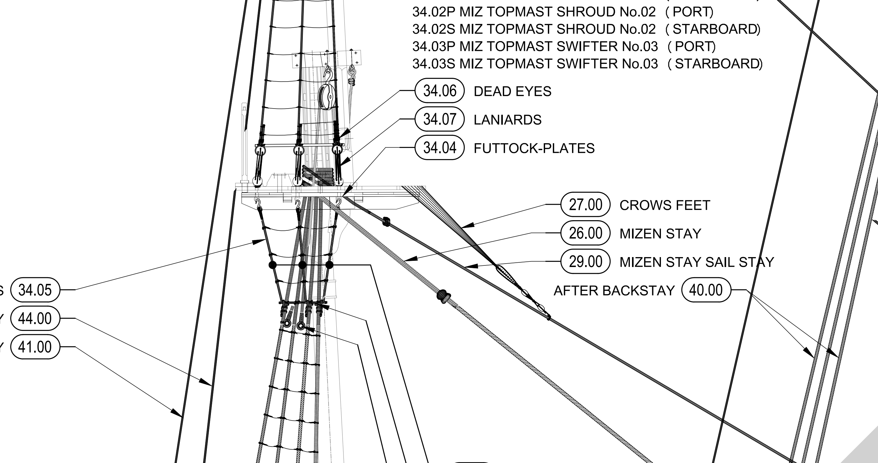
Hi Bill. The crows feet are to prevent the topsail catching under the top. The serve no other purpose. As such the carry very little load. Steel states that the Fore preventer stay is sometimes carried above the Fore stay. This means that the crows feet attach to the preventer. So the did not always attach to the larger stay. Mizen masts rarely carried preventers. It is most probable that the crows feet were attached to the mizen stayail stay. Steel states Bends to the mizen-staysail-stay with hanks and seizings. THE STAY clinches round the head of the mizen-mast, then reeves through a thimble seized in a collar lashed round the main-mast, and sets up with a laniard through a thimble turned into the stay, and an eye-bolt in the deck abaft the mast. In small ships, the mizen-staysail bends to the mizen-stay. Keep in mind that a lot of these finer details are conjecture and a matter of interpretation. The conjecture here is what is the definition of a small ship. Well Steel also gives us a clue as to what his definition is. Steel states (first paragraph of the section "mast making") Experience has therefore proved, that, in large vessels, three masts and a bowsprit, in smaller vessels, two masts and a bowsprit, and in the smallest, one mast and a bowsprit, are the most advantageous numbers for nautical purposes. So Endeavour was not classified as small in his work. However he does not show a staysail stay on his etchings of a 20 gun ship. Karl shows the staysail bent to the miz staysail stay. You would not be incorrect to omit the Staysail Stay and bend the sail to the Mizen stay. I think he missed the interference issue with the crows feet. This can easily happen when "standing and running rigging are drawn on separate sheets. This is my interpretation of the said stay on Investigator. However it possible that there was no staysail stay. regards Allan

-
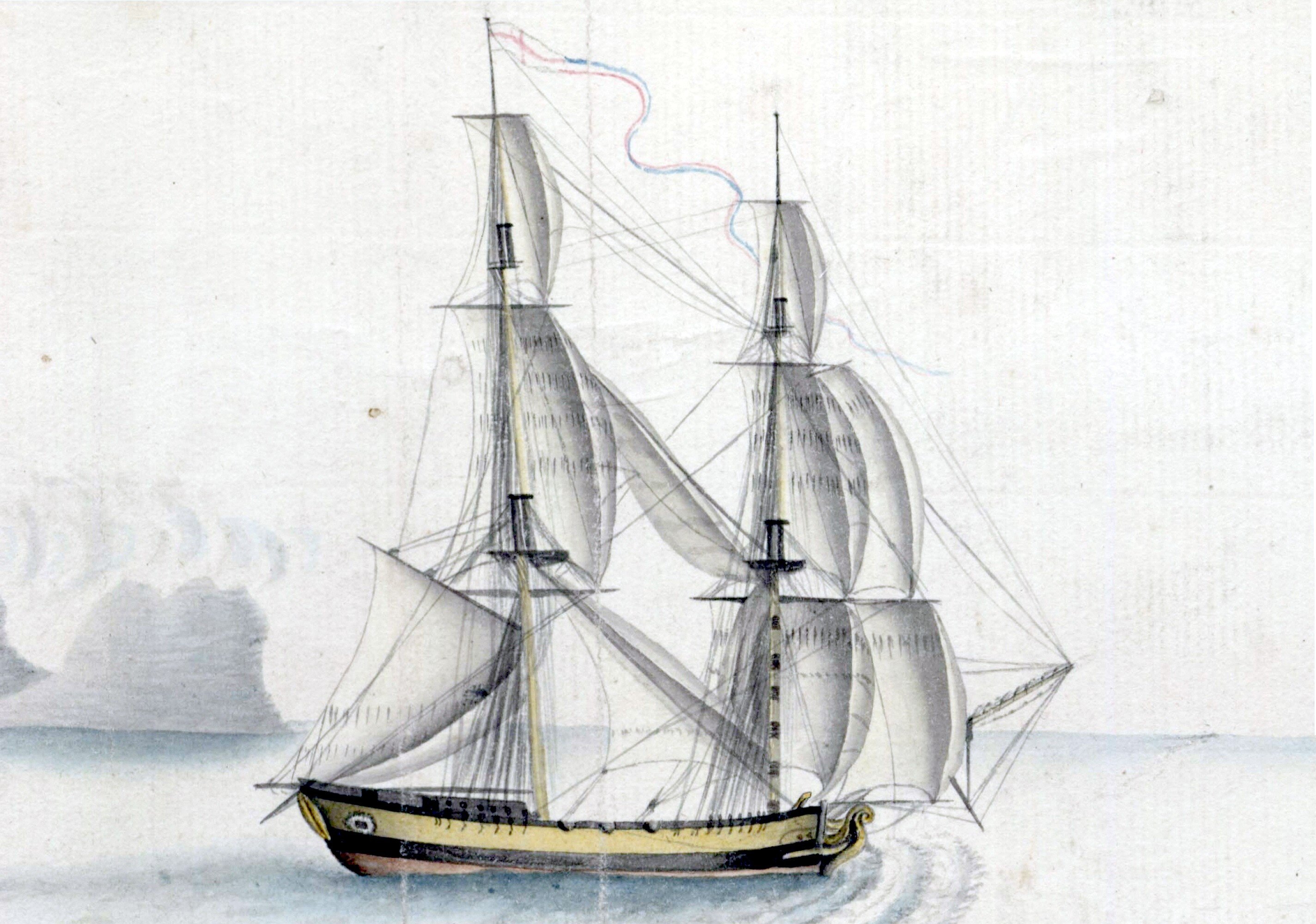
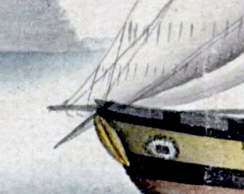
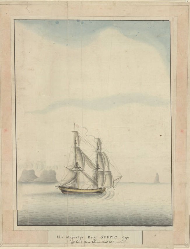
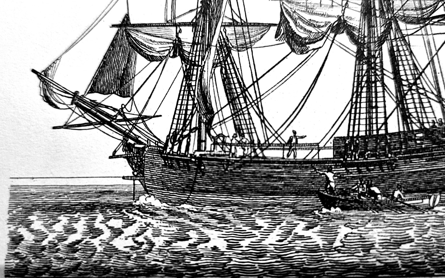
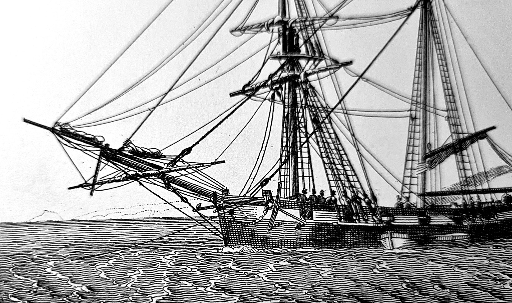
The masts are indicated on the admiralty draught by ticks or crosses. Here also is George Rapers watercolour of Supply. This is a very interesting painting. Note the boomkins on the stern. This painting is the best representation of HMAT Supply I know of. I have a high resolution copy at home. I will post it here when I am able. Regards Allan.
- 9 replies
-
- 3
-

-
- Artesania Latina
- First Fleet
- (and 1 more)
-
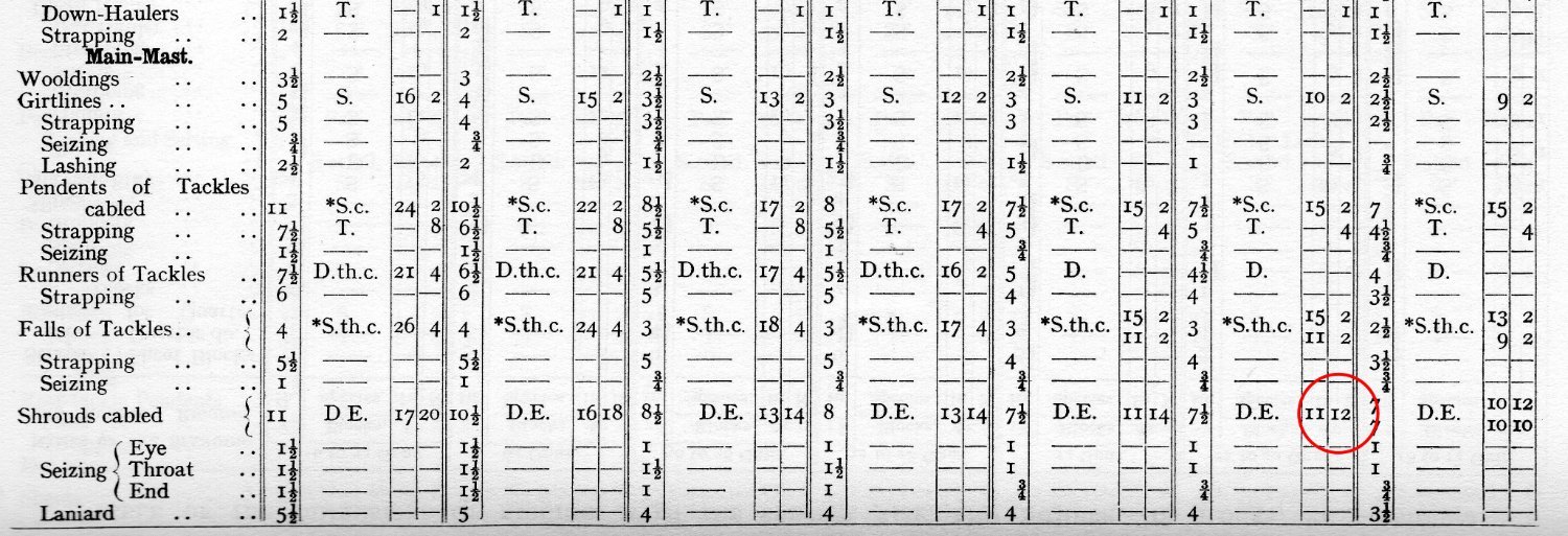
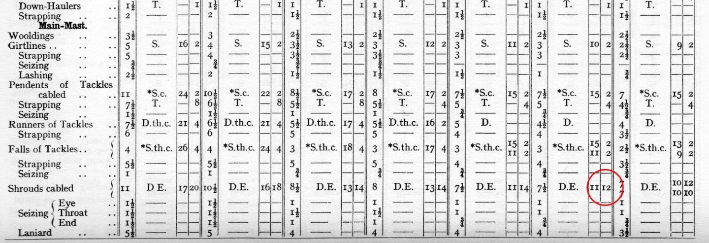
Hi Guys. I just purchased this. Well done great work Yuri. Page 88 Fore and Main number of shrouds should be 6 pairs I think. (Not 7) See attached extracts. Whilst reconstructing Investigator I have found errors in Steel's work. For example the proportions of the heel of the fore topmast does not fit between the fore trestle trees. Anyhow I am not trying to be critical, after all, every great work was penned by a human. (not sure about the future though) Regards Allan


.jpg.3d75ffdc291f1dd369bf2ec0618998ed.jpg)


.png.d6d3ff71fab4aee03e2da98d4446b52f.png)