
Richard Braithwaite
-
Posts
229 -
Joined
-
Last visited
Content Type
Profiles
Forums
Gallery
Events
Everything posted by Richard Braithwaite
-
 Many thanks for that! Im just preparing a presentation on "The Trireme, Salamis and Athenian Democracy" and there are some great soundbites in that video i might incorporate!
 -
Thanks kurt. I haven't done any brass blackening for about 40 years! So cant remember what I used last time. I need to do some experiments...
-
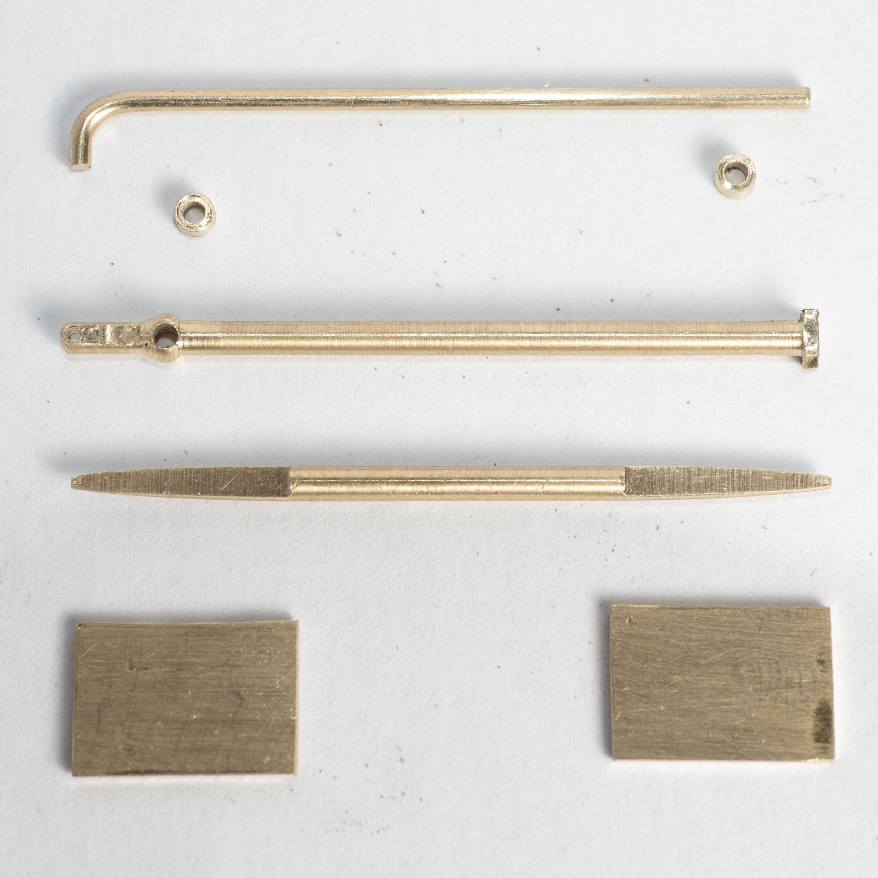
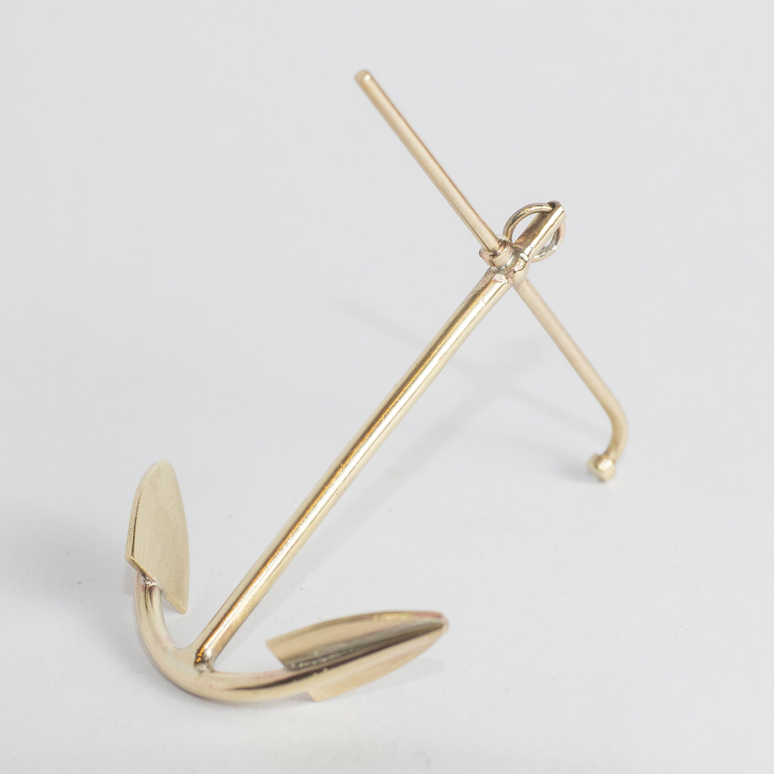
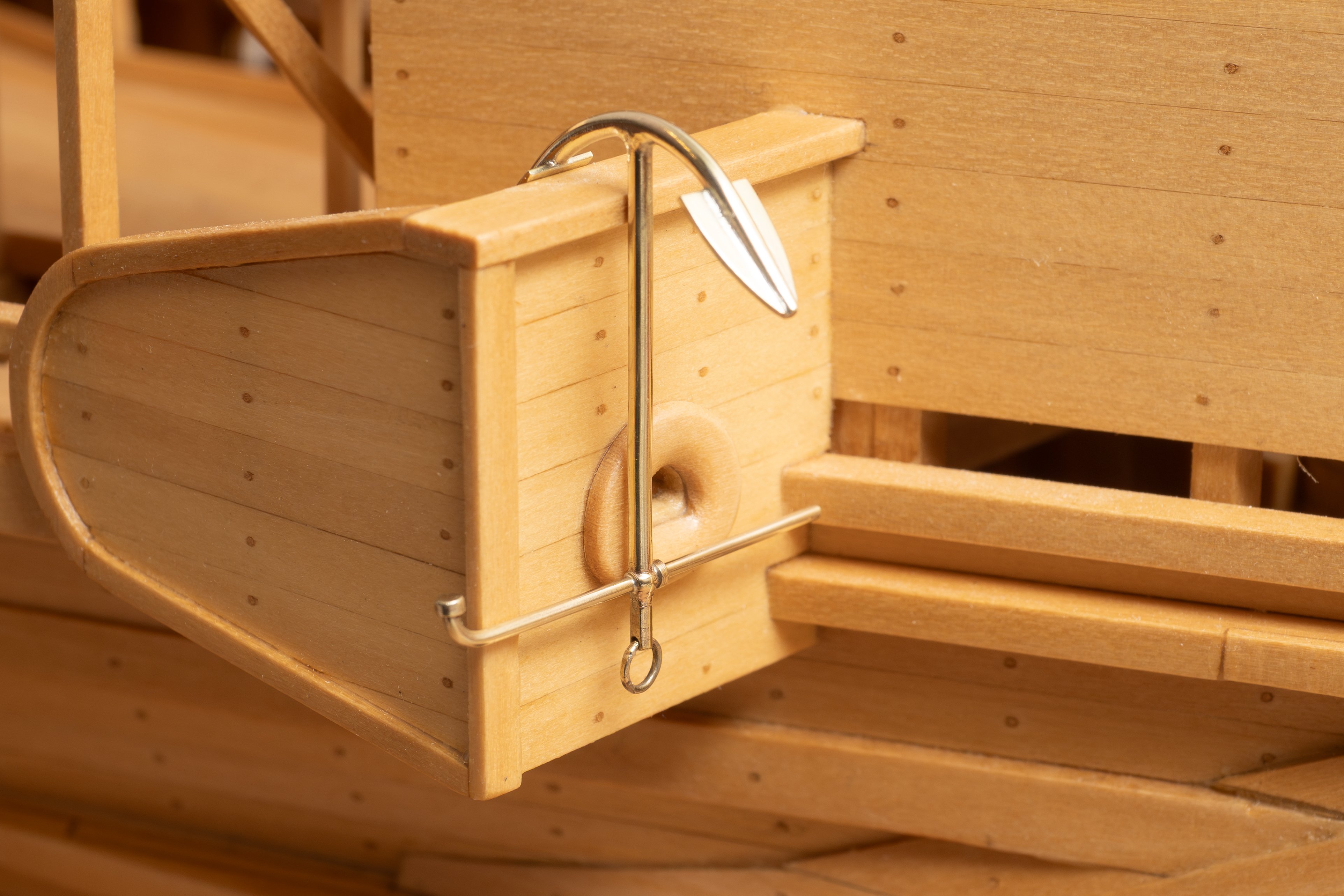
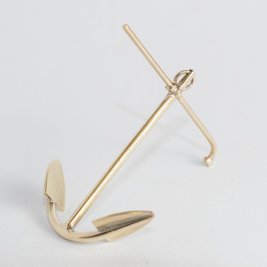
First anchor made today. First image is all the brass bits after machining/filing, ready for soldering. Next image is the completed assembly after cleaning. The scale size is 40mm length of stock. Weight 2.52 grammes which corresponds to 32kg full size in steel (i.e. assuming brass at 8500kg/m3 and steel at 7850 kg/me). I upped the (full size) diameter of the crossbar from 25 to 30mm from the design shown in the previous post, so this weight is about 12% over the design weight. Definitely one for my small blowtorch. I started using the big blowtorch (out of habit from making the ram), which melted the crossbar at my fist attempt... The anchors on Olympias appear to be painted black. I think I shall try blackening them with "Liver of Sulphur" and see what that looks like.. Here is the anchor in the boat in its stowed position looking quite blingy!! I remember doing some (very expensive) shiny anchors for luxury yachts at work so...


-
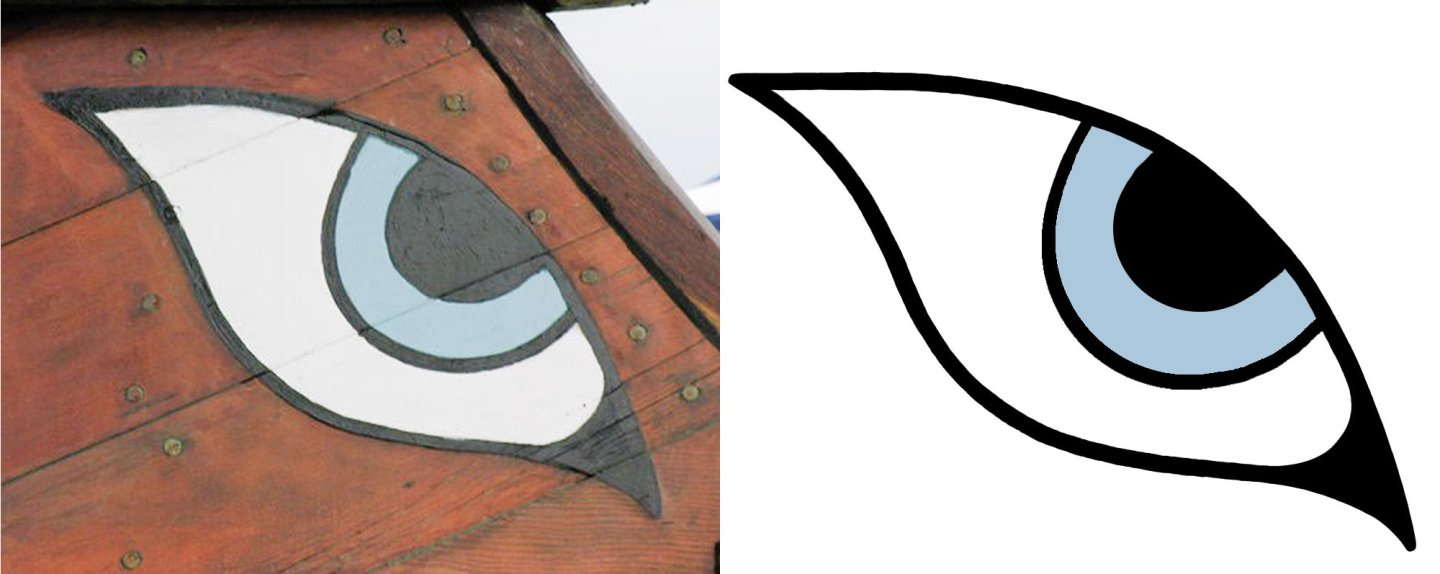
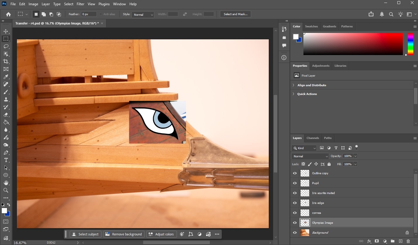
Working on the eyes for the bows of the boat. They were clearly repainted a number of times on Olympias and both the colours used and the style was changed slightly. also, as the photographs of the ship were all taken in different lighting conditions its quite difficult to read exactly what color was used for the "iris". I am planning to try using waterslide transfers for these eyes as an alternative to painting directly onto the model (from www.bedlamcreations.com) The process I've used to create the design is as follows (see photoshop screenshot below): 1. Took a photograph of my model perpendicular to the plane of the bow panel on which the eye is painted, load into photoshop as a background. 2. Selected a photograph of Olympias showing the eye relatively close up and taken roughly perpendicular to the plane of the eye panel and paste it into photoshop as a new layer 3. Scale and distort the Olympias image to match the perspective of the background. Made a little trickier because, while the planking on this panel in my model follows John's drawing they actually used a slightly different arrangement on the ship. however the lines of fastenings through to the underlying stiffening provides a more reliable guide... 4. Trace the eye in photoshop using different layers for the different components. 5. Try various colours for the iris to get a good "match". 6. export a png file (transparent background) to send to bedlam creations... After trying a number of colours for the iris I've settled for a relatively pale desaturated blue (Hex code #B1C8DA, RGB 177,200,218). Apparently this is a good match for a finely ground Egyptian Blue or Azurite pigment (which were both commonly used by the Greeks in 500BC) and also seems a good approximation to the photographic images I can find for Olympias (given the uncertainties of lighting etc.). The image on the right below shows the form of the png file that Im sending to Bedlam Creations. It will be interesting to see what I get back.
-
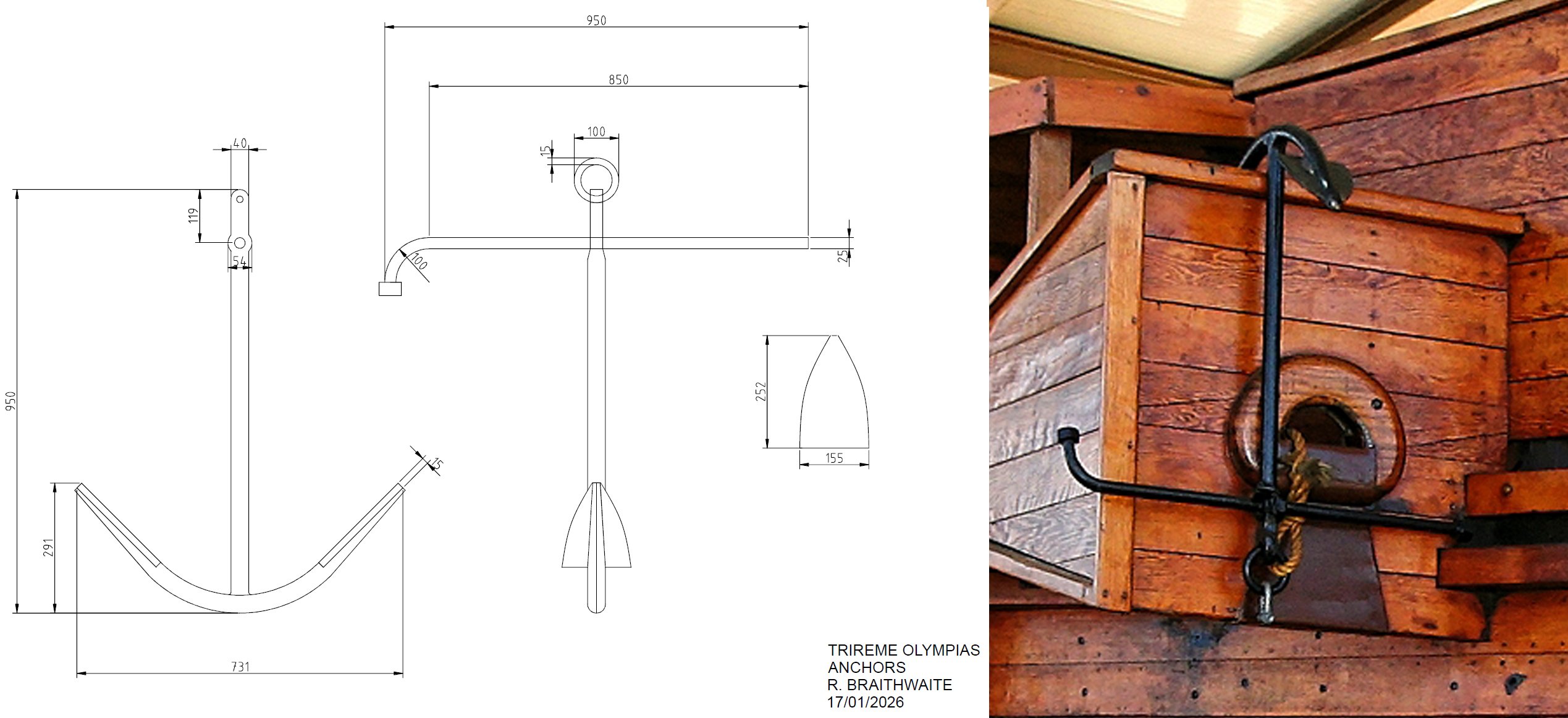
A Fisherman's anchor design scaled from a photograph of Olympias. Works out at around 27kg full size. there are two of them on Olympias one port and one starboard.. Seems quite light for a boat of this size, but I guess they were only needed for daytime anchorages in good conditions during trials. Even with actual triremes operated by the Greeks they would have been taken out of the water in rough weather so , I guess lightweight anchors might have been sufficient... There is an article on "Mooring" by Ian Whitehead in "The Trireme Project - Operational Experience 1987-90 Lessons Learnt" which describes a typical Mediterranean Moor where the vessel is lined up with her stern facing the beach, the anchor is then dropped to hold the boat inline while it is rowed backwards and secured to the beach with anchor and stern lines. I, have used this method, many times yachting in the Med, sometimes swimming ashore with the stern line to tie off to an Olive tree...

-
My copy of Ken Forans excellent book (Model Building with Brass) arrived today. Its a really lovely book and the quality of the work shown is fantastic. He suggests use of a Low melting point solder called "Stay-Brite" #8 with a much lower melting point than the high silver content solders I used in this project (cirva 250 degrees centigrade vs 720 degrees for the "Easy" grade of silver solder I used). I've never tried this but I can really see the appeal of not having to heat ones whole project to near melting point temperatures each time you do another joint! If I was doing this again I think I would have tried this material. Not sure if it would have had the strength for the fillet joint between the 0.2mm brass and the 1mm (where the contact width of the joint is only 0.2mm) without leaving a large fillet, but certainly sounds like it would be worth a try. Im probably not going to be ramming any other model triremes, so a high strength ram is probably not required!
-
Ram fixed to the model with 0.6mm "Tiny nails" from www.drydocksidemodelsandparts.com.


- 319 replies
-
- 20
-

-

-
Thanks for all the positive comments. Its been one of the more challenging little subprojects ive done...
-
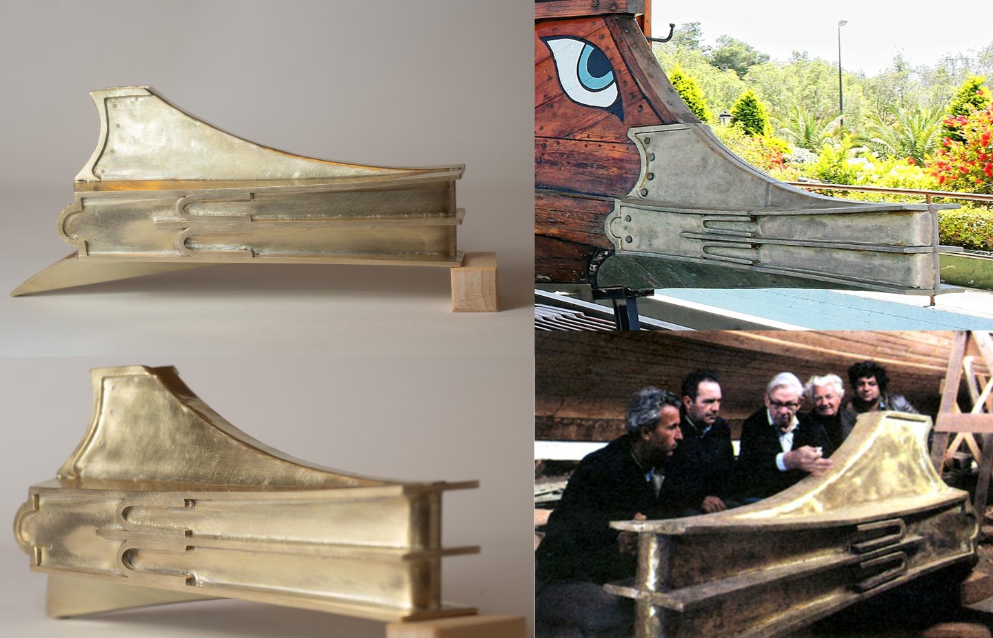
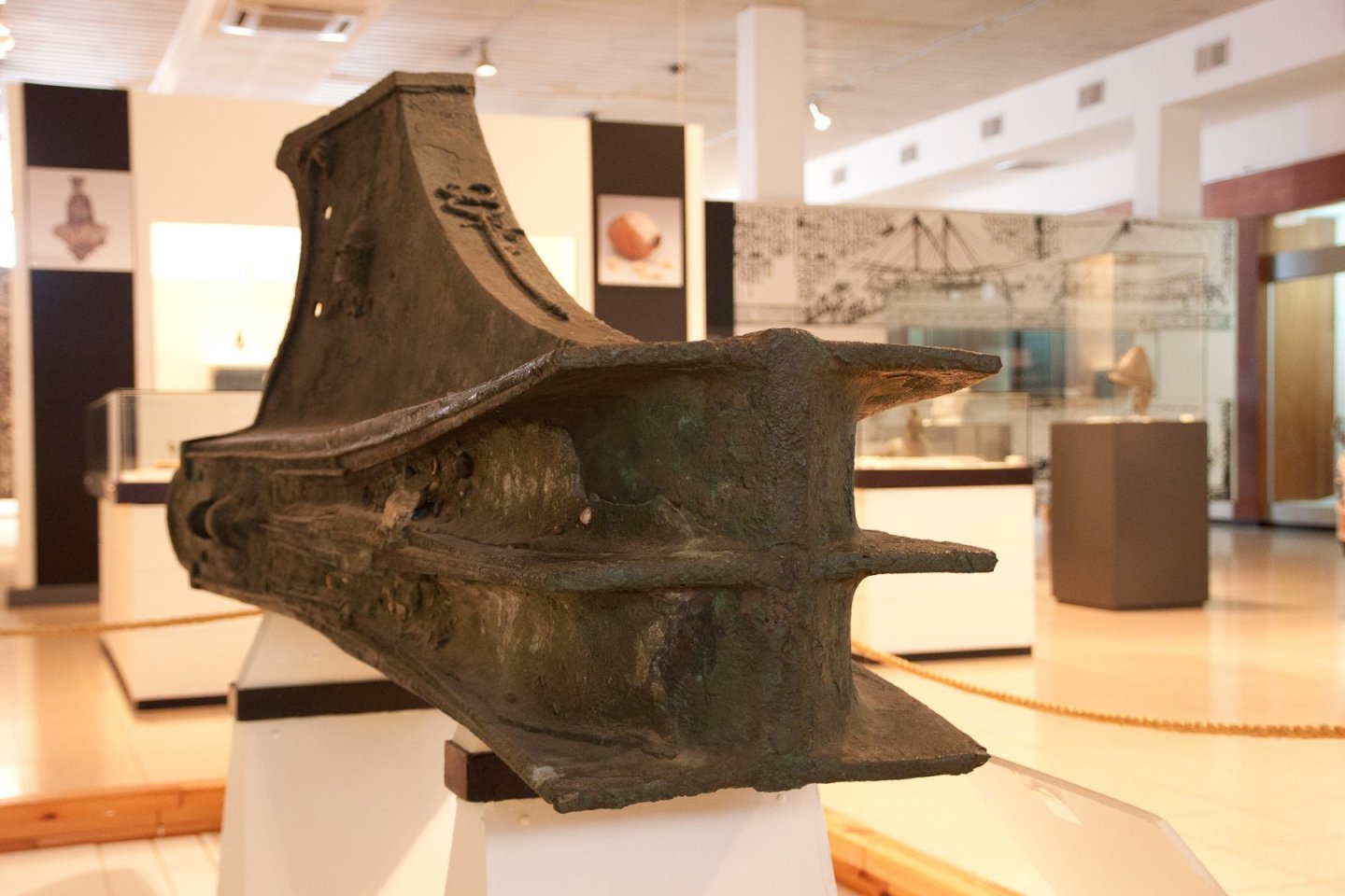
Here is my ram with the extra "decorative" bits added (on the left) with Olympias's ram on the right. John Coates is the man in the middle modelling their new fabrication... Its not perfect but I'm reasonably pleased as its my first go at a complex fabrication like this with silver solder. Interestingly it wasnt the long welds that were the most difficult. All the tiny decorative bits were surprisingly tricky. I used extra easy silver solder to reduce the risk of melting previous joints and plenty of Thermal gel plastered over everything away from the actual joint I was making at the time. I thought I wouldnt need as much heat input so started off with my smaller blowtorch, but couldn't get a melt. In fact it took a lot of effort with the large torch to get the solder to flow. I guess that is because the thick plating around the joints was sucking the heat up. In fact one of the issues of this fabrication is getting enough heat into the 1mm plate without melting/distorting the 0.2mm plate its attaching to... Ive been trying out a couple of patination options (ammonia vapor and liver of sulphur), but I'm thinking I may just let it tarnish naturally... Here is an image of the Athlit ram that John based his design on:
- 319 replies
-
- 12
-
-
-
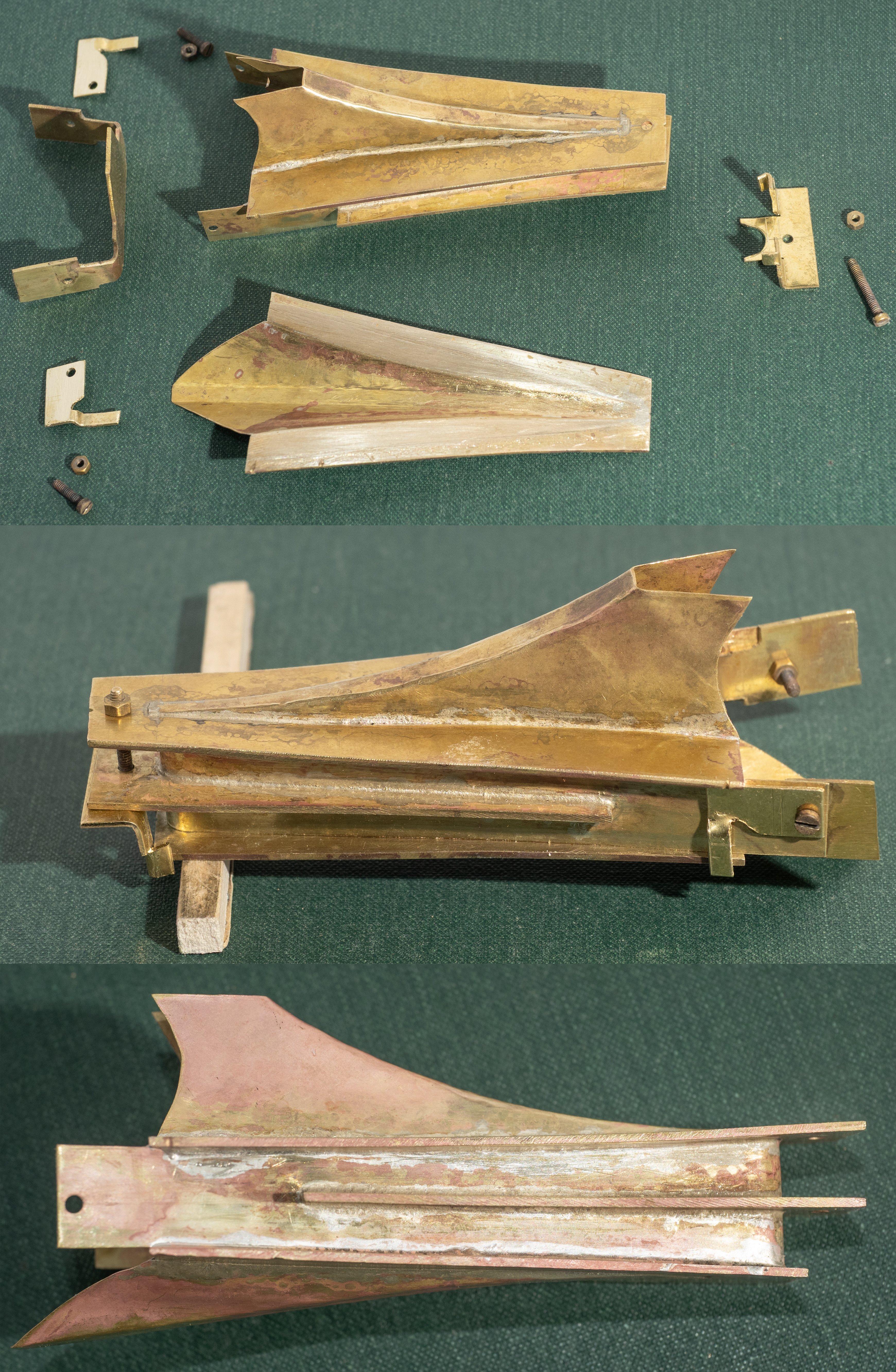
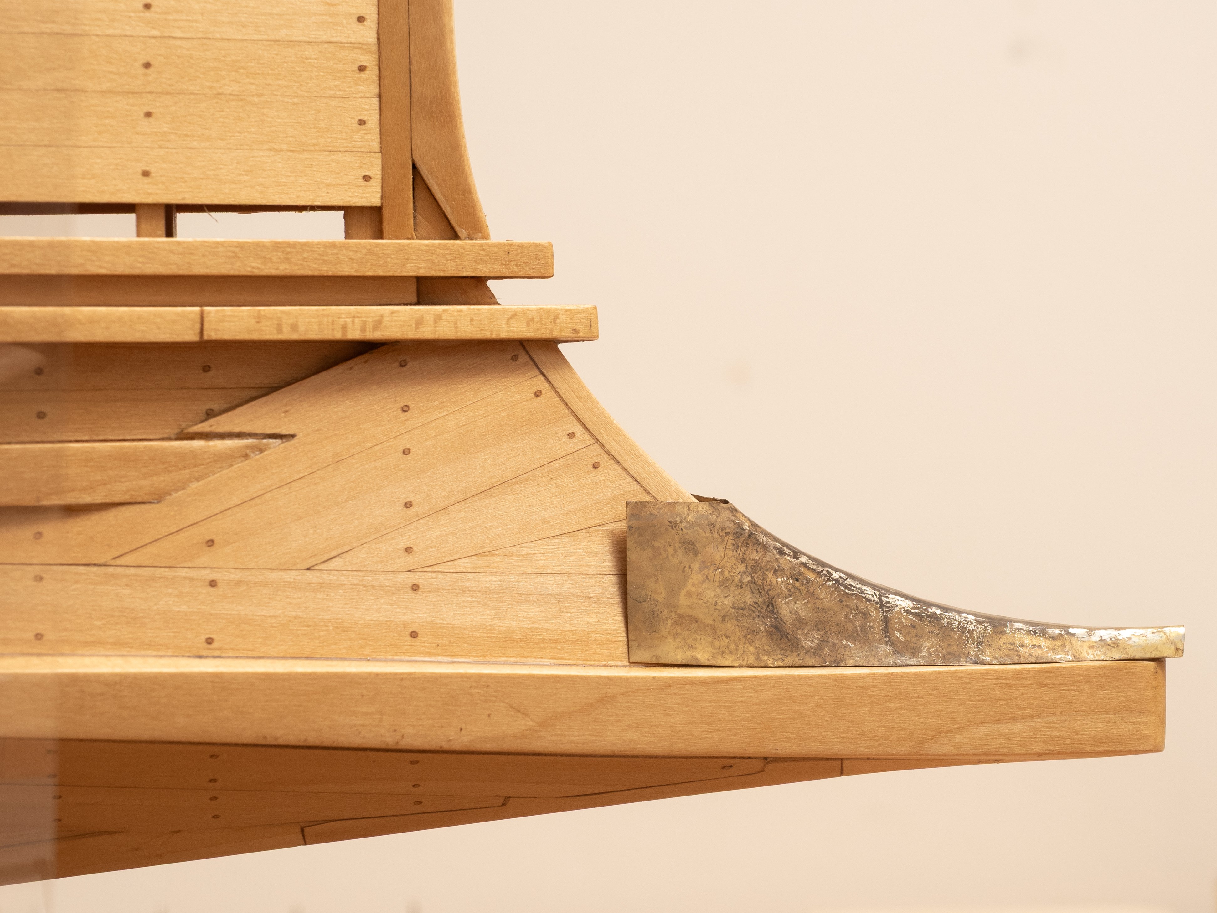
Attaching the lower subassembly: I've been gearing myself up for this one. The last of the major joints and the final confirmation of whether I can make this fabrication accurately enough to fit my model. The upper image shows the two subassemblies to be joined and the collection of items Ive made to try to keep them aligned during the soldering operation. the next image shows a dry assembly of the pieces. A lot of going backwards and forwards from the model to adjust the taps on my fore and aft jigs so that the two assemblies are aligned. The lower image shows the ram assembly after is bath in "Picklean" The good news and huge relief is that it actually fits! It was the right decision to go for fabrication rather than lost wax casting. Although I could probably have made a accurate 3D model by photogrametry and modelling in blender all the uncertainties over shrinkage during the casting process would have been a real problem. Also the minimum casting wall thickness of 0.6mm was a show stopper for me. There is still quite a lot of work to do, shaping the ram plates and fitting various decorative pieces, but the basic structure is there (and hopefully survives the rest of the work!). And then the cleaning...All that copper discoloration to remove and all that silver solder (next time I should use that yellow ochre powder Kurt refers to above...)

- 319 replies
-
- 12
-
-
-
Some thoughts on filing...I've been doing a lot of this recently and it made me think of my time at the Devonport Dockyard Apprentice Training Center when I first joined. The first thing they do with Apprentices is filing. Lots of filing, and then more filing, and just when you thought you had done enough filing... more filing...(e.g. now make a chess board out of 64 identical cubes of steel...). Its amazing how accurate you can be with a file with the right attitude and suitable encouragement! I asked the trainers what this was all about and they replied that it is rather like getting raw military recruits to march up and down the square for hour after hour after hour.... Its all about taking a teenager of the street and engendering the right attitude! I'm still reaping the benefits now...
-
Kurt, Many thanks for the suggestion. Just ordered my copy of Ken Foran's book on amazon. All the best Richard
-
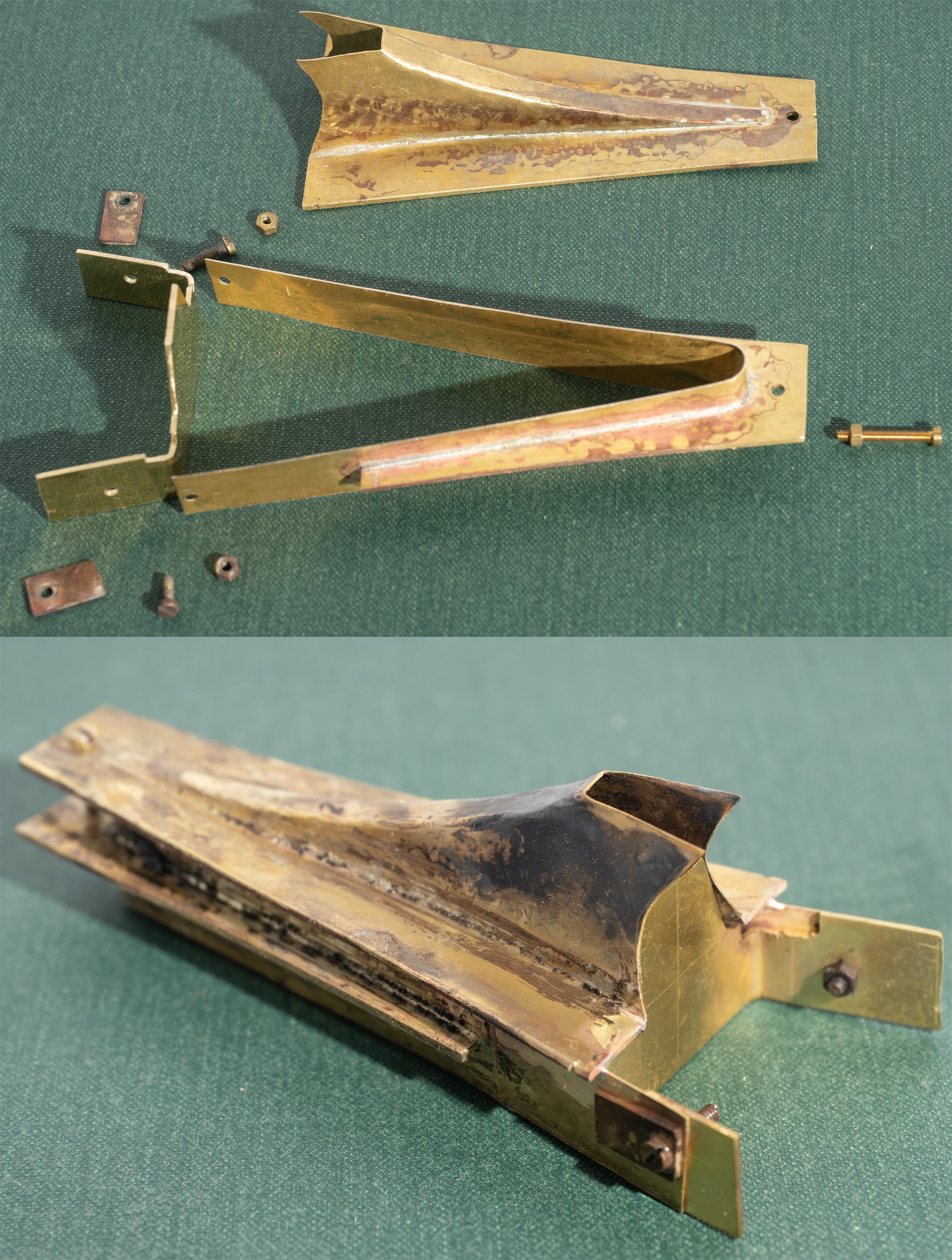
Today attached the Mid ram assembly to the upper ram assembly. 1 The upper edge of the mid ram cladding was shaped to fit the curve of the upper ram plate. This requires a high degree of accuracy as silver solder has very little gap filling ability. 2. Constructed a jig to hold the aftermost (highly flexible, particularly when heat is applied) part of the mid ram cladding firmly and at the right distance apart to closely fit the ram timbers (upper image below) 3. The existing welds were protected using "TEMPGUARD" heat dissipating gel to reduce the risk of them falling apart during the soldering process. 4. Silver solder/flux paste (Easy 705-725 deg C to get some distance from the medium solder used previously...) applied and the two pieces brought together for soldering. I ended up using the large torch for this even though it wasn't possible to be so precise with the heating,a s I found I needed the heat input. 5. The result (bottom image) after soldering but before jig removal and "pickcleaning". I was very pleased at the accuracy I achieved with this. The ram fits very snugly on the timbers (so far). I also managed to engineer the jig to keep it clear of any solder so it didn't require the endless filing I had to do previously. I am learning as I go along...

-
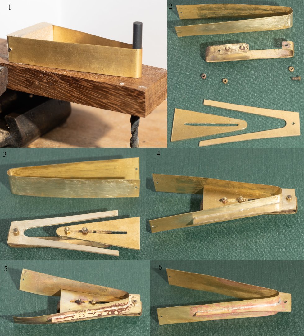
Mid part of the ram in construction (Part 1) Image 1: Shows the mid cladding plate being formed around a 5mm drill to fit the radius at the front of the wooden ram substructure. Image 2: The Mid Ram plate (the fork shape piece at the lower right hand corner of image 2) is shaped to fit the wooden ram substructure and the slotted plate is shaped to fit inside this with a clearance of 0.2mm all round to allow for the thickness of the cladding plate. The drilled bend plate in the middle of image 2 is designed to hold the mid ram plate firmly while the slotted plate can be pushed forward to force the cladding plate to the right profile. I have soldered (using medium silver solder) the two bolts that hold the slotted plate as I found that it was over fiddly having these loose). Image 3: The silver solder (medium solder/flux paste) is applied to both the cladding piece and the ram plate and then the cladding plate is lowered into the jig and the slotted piece pushed forward to force the two parts together in the required alignment. Image 4: Shows the result with the silver solder paste applied. Image 5: Shows all the distortion that takes place with the 0.2mm plate when you heat it up high enough for the medium solder to melt! Image 6: shows it after cleaning with picklean and roughly straightened out. Clear as mud? Ive left a couple of mm of "green" each side of the cladding sheet which I now need to shape to fit the space between the upper and lower ram assemblies...
- 319 replies
-
- 10
-
-
For all of you who are NRG members I have done a shop note in the latest journal ( Vol 70 No 4) about the 1:24 scale Athenian manikins that i built for this model that expands on the content of this log.
-
Here are the upper and lower pieces and the mid ram plate loosely held on to the wooden ram structure. I'm quite pleased with the fit I've managed to achieve so far (there have been a few "test pieces" which didn't work out! - but were useful for practicing soldering of these very thin plates...) . The real challenge is going to be aligning the three pieces when I connect the three pieces together.

- 319 replies
-
- 10
-
-
-
Here are some images of the lower part of the Ram in construction: The lower image is a dry fit of the jigging/fixing arrangement prior to application of the solder paste.

-
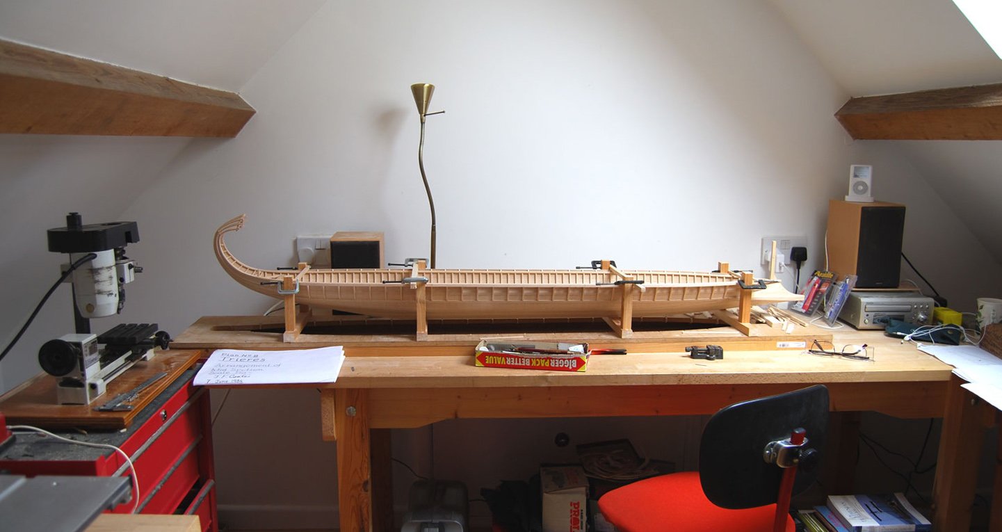
Loracs, The plans I am using are hand drawn my John Coates for the full size Olympias reconstruction. They can be obtained from the Trireme Trust Archivist (Jude Brimmer <archivist@wolfson.cam.ac.uk>).
-
Upper part of ram assembly in construction: Upper image shows the component pieces (upper sheathing from 0.2mm brass and upper ram plate from 1mm brass) together with a jig/clip to hold the two pieces in place while brazing. I used a silver solder paste of medium melting point (720 - 765 degrees centigrade) from Cooksongold and applied it to both parts along the contact line. By experimenting on a test piece I found that the larger blowtorch was needed to get enough heat into the piece for the solder to flow. The results are shown in the middle image. As you can see excess solder has flowed over part of the upper ram plate which will need cleaning off. The clip/jig was removable, but the thin strip of brass had soldered to the piece so this needed filing away as well. The lower image shows the piece after soaking in "Picklean Safe pickling powder" (again from Cooksongold) and some cleaning with files sandpaper and a wire brush. I'm planning to leave final cleaning until the entire ram is constructed (there is a lot more heat to put into it before then). Apparently the pinkish areas are caused by loss of zinc on the surface of the heated brass, it seems very superficial so, hopefully I can remove it in the final clean...

-
There is a recording of an online workshop I did on this project with the Nautical Research Guild at the following link (you need to be a member to access these videos...): Nautical Research Guild - Authorization required A lot of the material for the workshop presentation is covered by this build log, but it does also cover some additional areas such as the early stages of the build (hull construction etc.), general discussion about the ship type etc.
-
Has anyone tried this? apparently it grows very slowly and has a very fine grain. I recently attended a presentation by David Hulse in Dartmouth. He has spent most of his life researching and building exceptional models of Atmospheric Steam engines, which he has donated to our local museum in Dartmouth. They are built to a scale of 1:12. He has used Japanese Oak for the wooden components and it looks very effective at this scale. He was Chief Engineer at Royal Doulton and used his knowledge and expertise to develop a process (and build the machinery) for producing thousands of 1:12 scale bricks using 17th Century methods for his models. Worth checking out his models at: The Hulse Collection - Dartmouth Museum
-
Not a bad idea. May try to source a softer alloy, although seem to be able to bash this plate into shape with enough anealing. Silver is a thought...The Athenians did pay for their fleet with silver, but there doesn't seem to be any evidence that they made the ships out of of it! I have several other issues to explore. 1. solder colour match. Ive got both gold and silver solder to experiment with. I did think of making the whole thing out of 9 ct gold, until i worked out the cost.... 2. making the thing to fit... probably would have been better to make the ram and then make the ship to fit. Oh well....
-
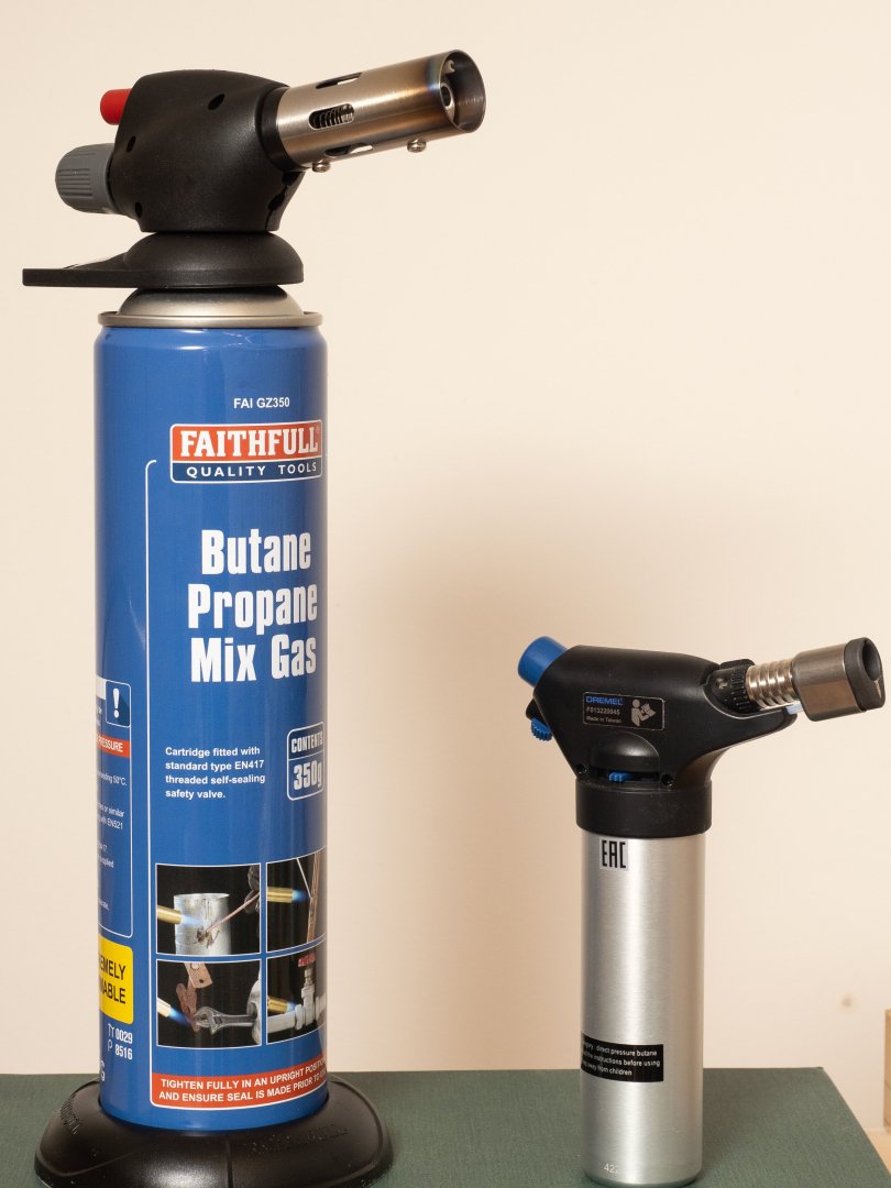
The answer, of course, is get a bigger blowtorch... My little Dremel blowtorch wasn't capable of heating the whole piece up enough to anneal it sufficiently. Last night I got a really hot (open) coal fire going and tried to use that. Placing the piece amongst the glowing coals did generate enough heat to get it glowing red hot, but it was difficult to control and I ended up melting the ends of two attempts. So today i bought a bigger blowtorch (the one on the left). That did the trick. Plenty of heat to get the piece red hot with sufficient control to avoid melting any of it... The results of about 15 cycles of heating a piece of 0.2mm thick brass sheet to red hot, quenching in water and bashing with a brass hammer over my former can be seen below. Not quite trimmed to fit yet, but I've achieved the shape I need...

-
The copper is a bit thin for brazing, but it does seem more maleable, so a copper ram might work (not sure about colour, although i could always get it electro plated...)
-
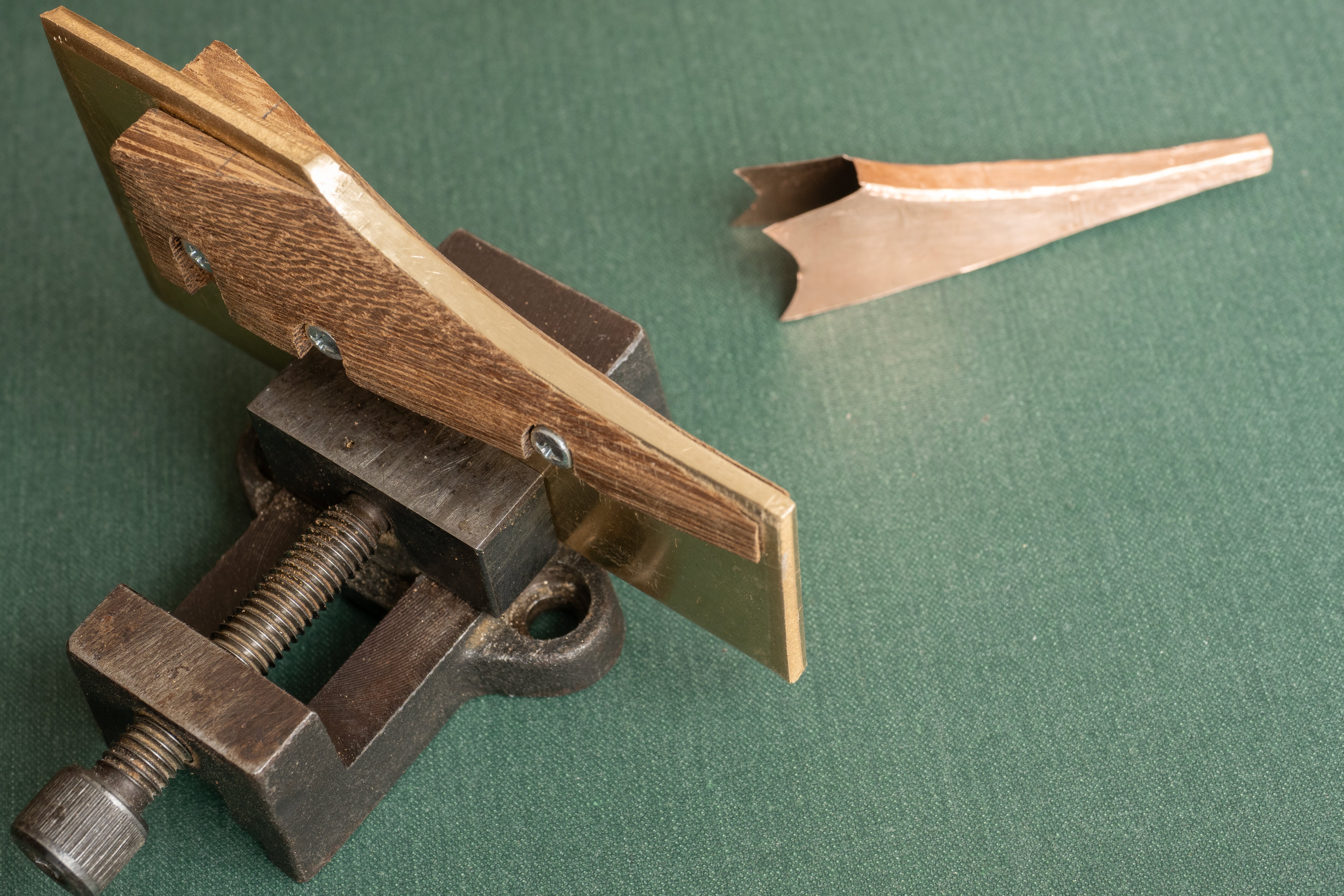
For some time I've been considering whether to cast the ram (like the archaeological Athlit Ram) or fabricate from plate (as was done on Olympias). Recently I had a go at estimating the weight and determined that the majority of the sheath needs to be 0.2mm brass (equivalent to 5mm plate full size). That excludes casting since the minimum achievable wall thickness seems to be around 0.6mm. So, the next thing is to determine how Im going to put it together and out of how many pieces... I've produced this former to look at the feasibility of shaping a single piece of 0.2mm brass for the top part of the sheath. First attempt in 0.1mm copper shown alongside the former. This worked quite well without any annealing. first attempts with brass have been difficult but, hopefully some more thorough annealing will make it work. Otherwise its two pieces with an overlap over the top. Either way Im going to end up with a lot of soldering stages so we'll have to see how that will work out...