realworkingsailor
-
Posts
3,272 -
Joined
-
Last visited
Content Type
Profiles
Forums
Gallery
Events
Everything posted by realworkingsailor
-
 I think the best way to figure out how and why towns and villages were settled/created is to have a good look at the municipal/township/county archive records and see who owned the land prior to the railway coming through. In North America, as the railway networks expanded there was considerable land speculation along the planned or proposed routes, and even theoretically possible routes. There was a ton of money to be made by buying up those then (nearly) vacant, remote rural properties for virtually pennies and subdividing and re-subdividing and then selling off or leasing, at considerable profit, the small lots to the merchants and settlers who would inevitably follow the railroad. It’s very likely that in this case, there were two or three (or more) landowners who held large acreages adjacent to the railway junction, and the resulting spacing between the initial town buildings was due to what deals could be made between these speculators and whoever came later and wanted to set up shop. Andy
 -
I would add IHYLS (I Hope You Learned Something) to that list. Sometimes his pronunciations can be a bit jarring, but, he does inject a good deal of wit and humour in his videos. I think Rex has mentioned him in a couple episodes of his own. But yes, wading through the tsunami of AI slop that is propagating through YouTube is getting to be a pain. I wonder if it is worth creating a post on here where we can curate a list of reliable, accurate and non-AI military history channels that are worth watching? Andy
-
I think your scene is pretty crowded, busy and colourful as it is, the column seems to both disappear in the activity while reducing the “breathing space”. It might fit better in a simpler, larger, scene. Andy
-
Say it like Boromir 😆
-
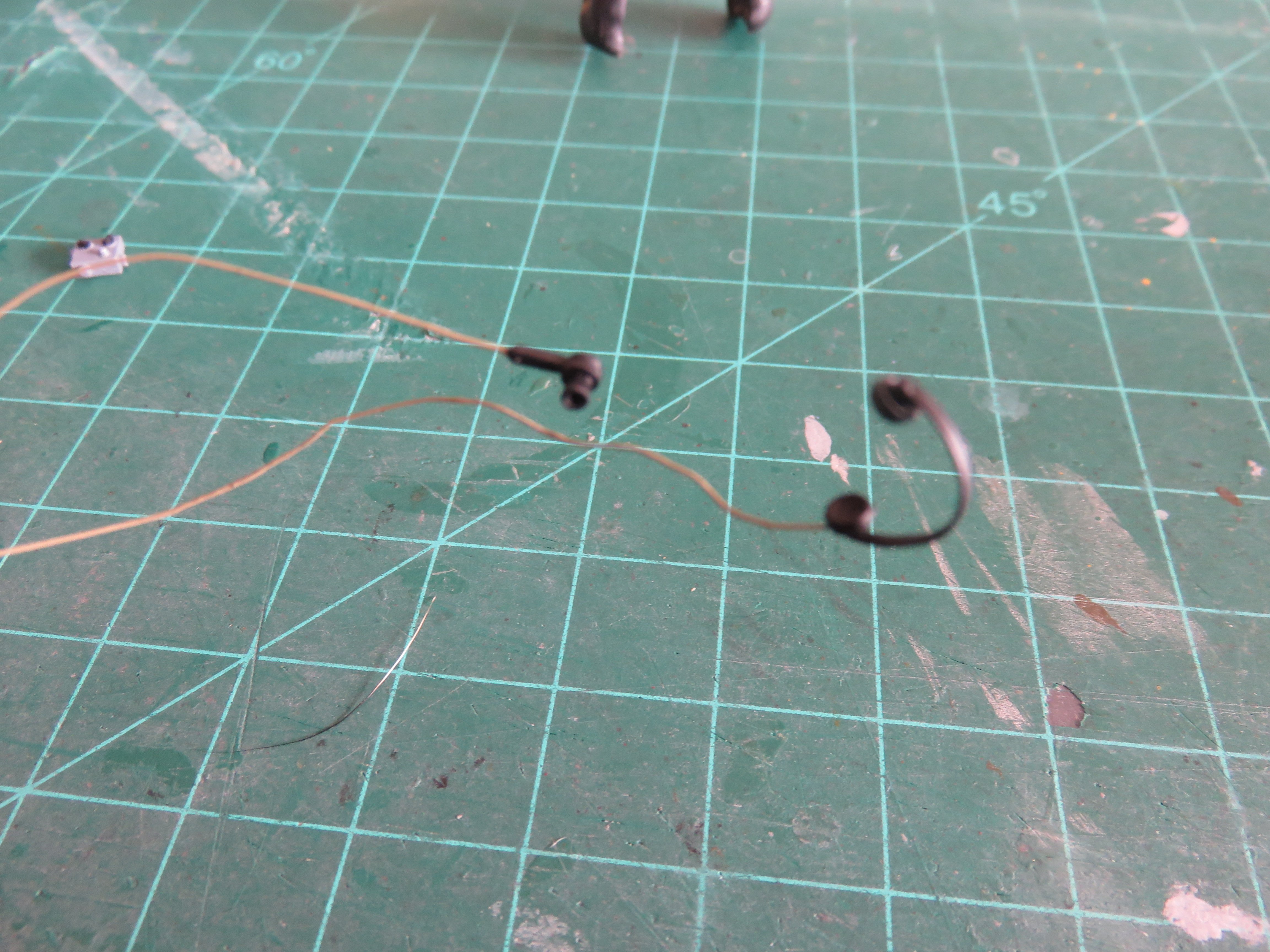
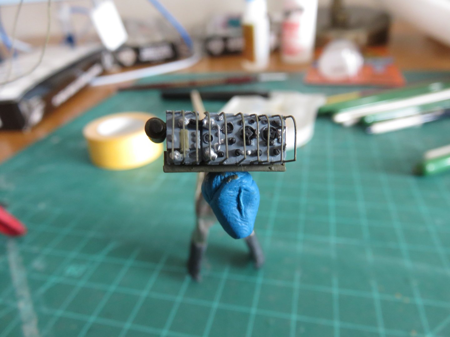
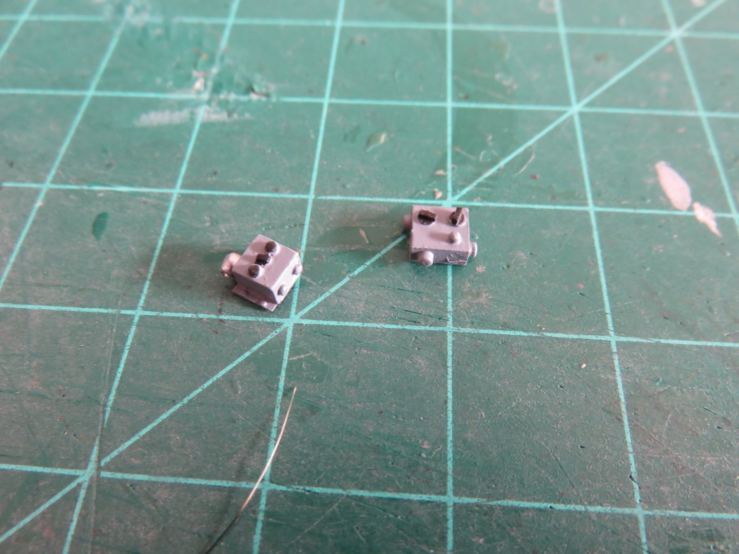
I hope everyone had a good Christmas! I have been busy the last couple of days painting the No. 19 Radio set and all its various components, and getting the final bits assembled. I took my cues from a restored version found on wikipedia, as well as a few unrestored radios, to determine what colour would be appropriate. The outer casing looked to be a dark grey/green colour, and the face plate a blue-grey. I used a mix of Vallejo RAF Dark Slate Grey and RAF Dark Green for the casing, and the front guards and Vallejo RAF Ocean Grey for the faceplate. The front guards where painted on the PE fret, as it would have made painting the various dials, switches and knobs rather challenging. I painted the microphone and headset black, and the wires in a khaki colour. (Apologies for the out of focus image, the parts are being held by the fine wire, and they jiggle around at the slightest waft of air). I still need to figure out where on the radio set they plugged in. A couple of other control boxes I also painted RAF Ocean grey. The only thing left to paint is the antenna mast that will be mounted behind the driver's door. All of the remaining parts will be mounted in and around the work table I made earlier. As always, thanks for the kind comments and "likes", always very appreciated! Andy

-
The Airfix 1/48 Lysander might be of interest, although not open cockpit, the canopies can be left open. Definitely quirky! Great job on the Arado, though! Andy
-
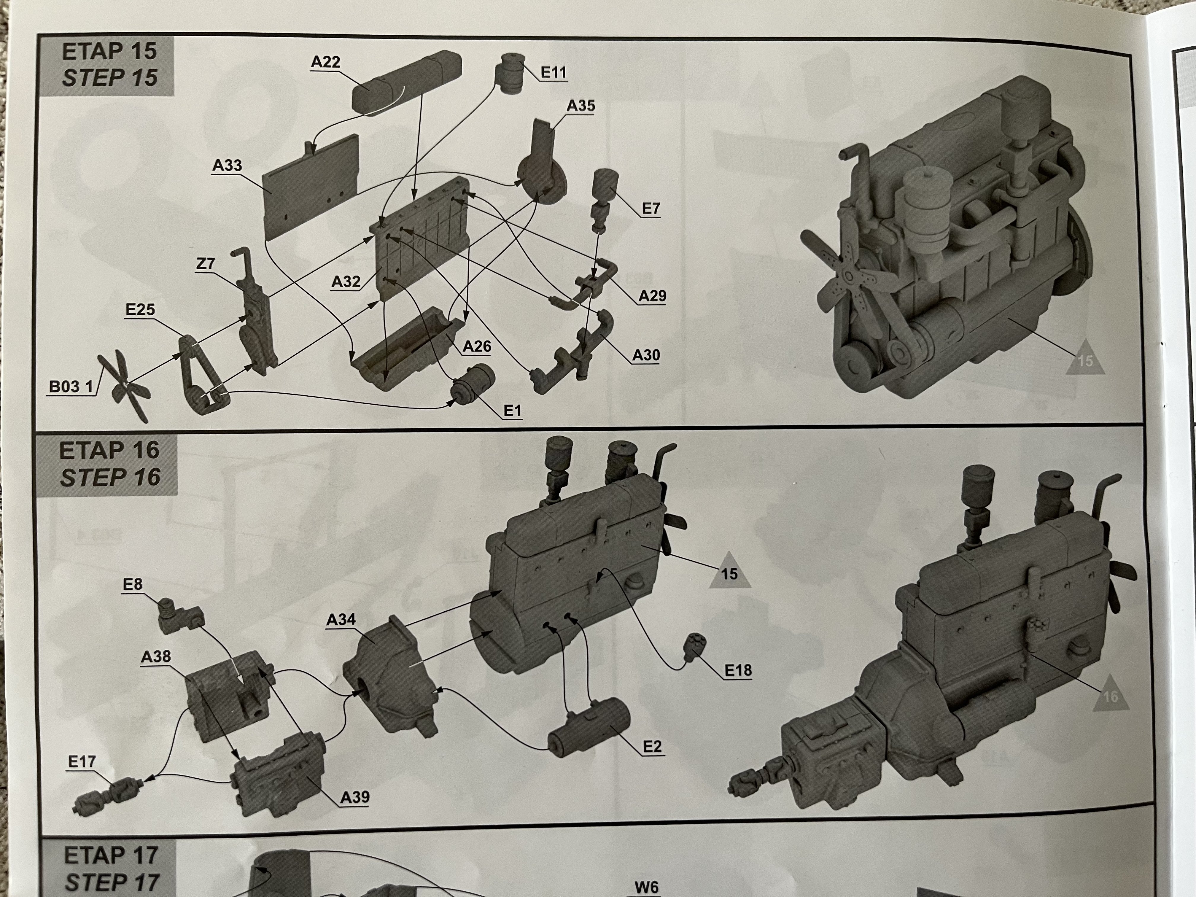
Thanks Ken! I may have mentioned before, but this is definitely not a kit for beginners! There’s considerable ambiguity to be navigated. While many parts have some indication as to where they are to join (shallow recesses or slack locator pins), it’s hardly what anyone would call a “positive fit”. In other cases it’s up to the modeller to figure out on their own. The instructions are a black and white 3D CAD rendering type with and exploded view showing the parts and their orientation, beside a completed view: But as far as what order the parts go on in each step???? (Also looking at the part numbers, the engine has parts from no less than three different sprues and some PE, other assemblies I could count at least six sprues were needed) Of course, none of this is helped by me going off on a scratch building tangent for the cargo bed! 😜 No matter how you slice it, this kit, (and its IBG cousins), is a project, but if you’re willing and able to tough it out, the results will be worth it. Andy

-
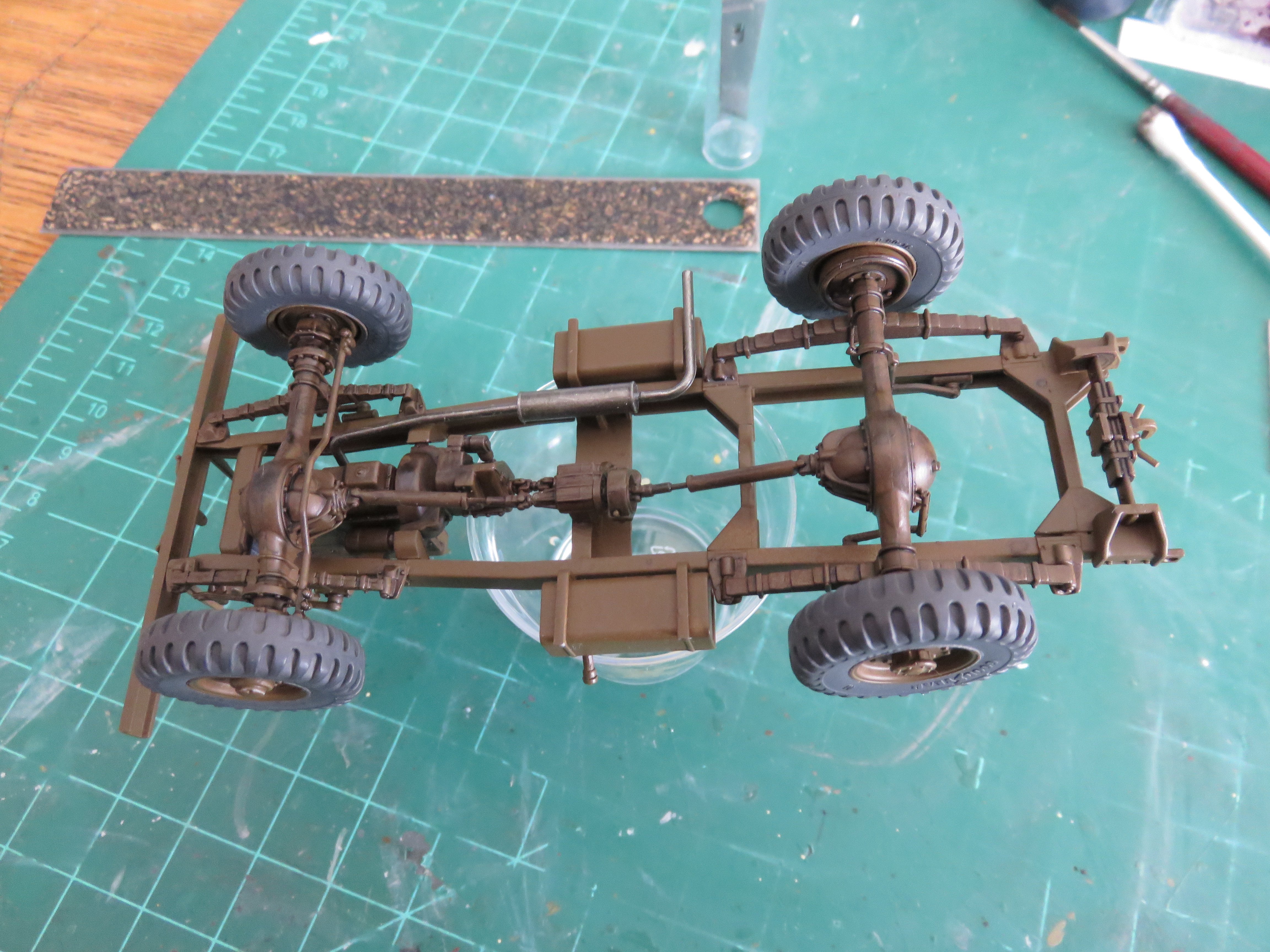
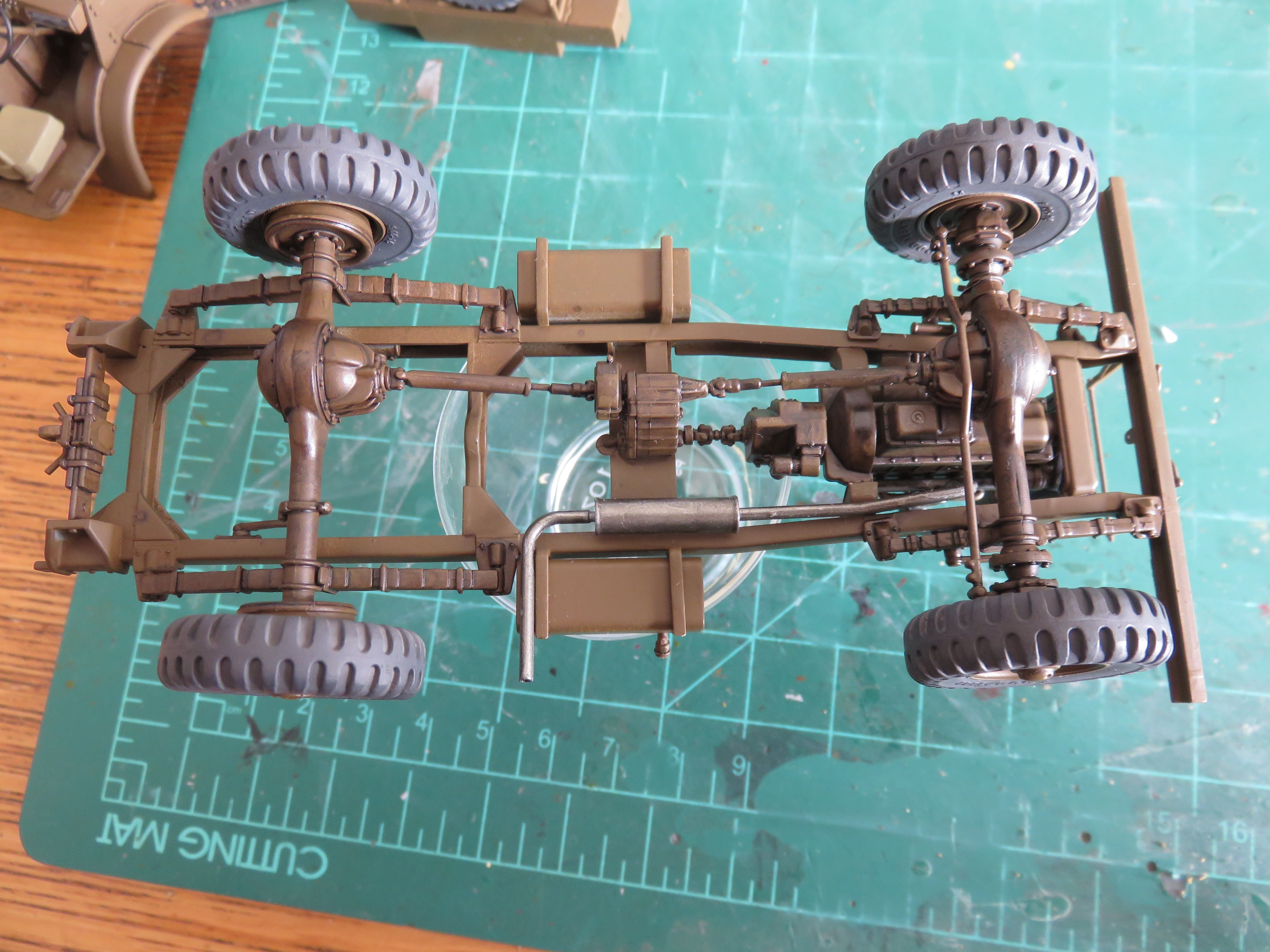
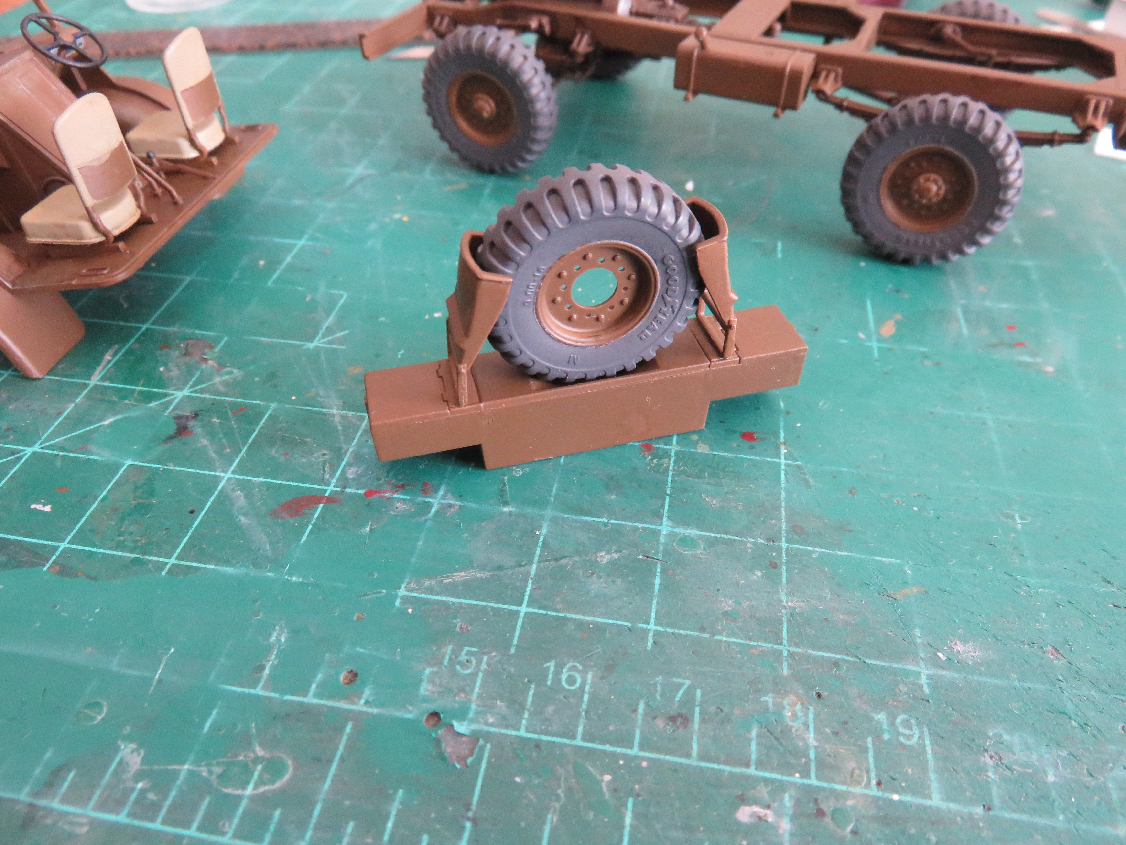
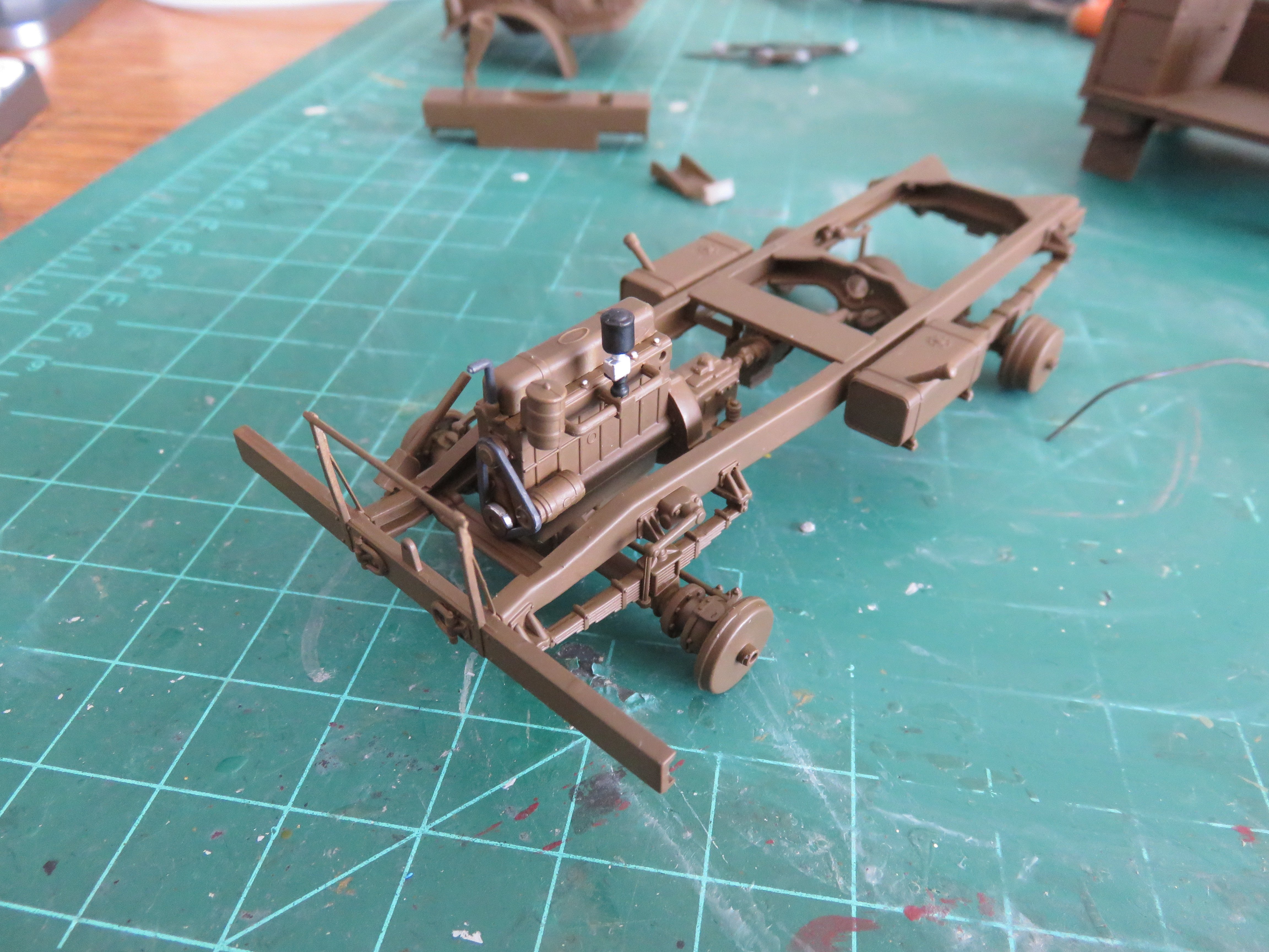
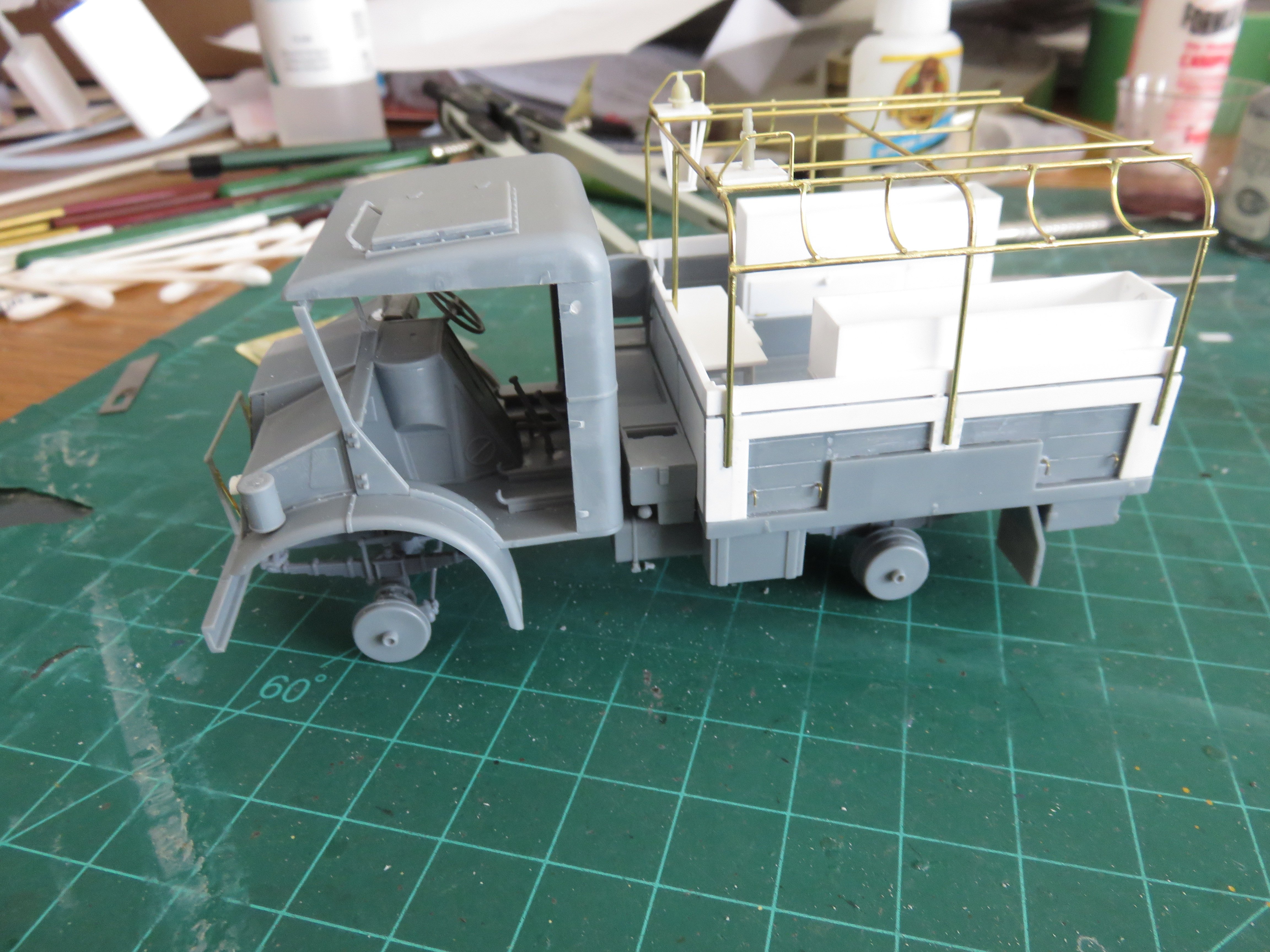
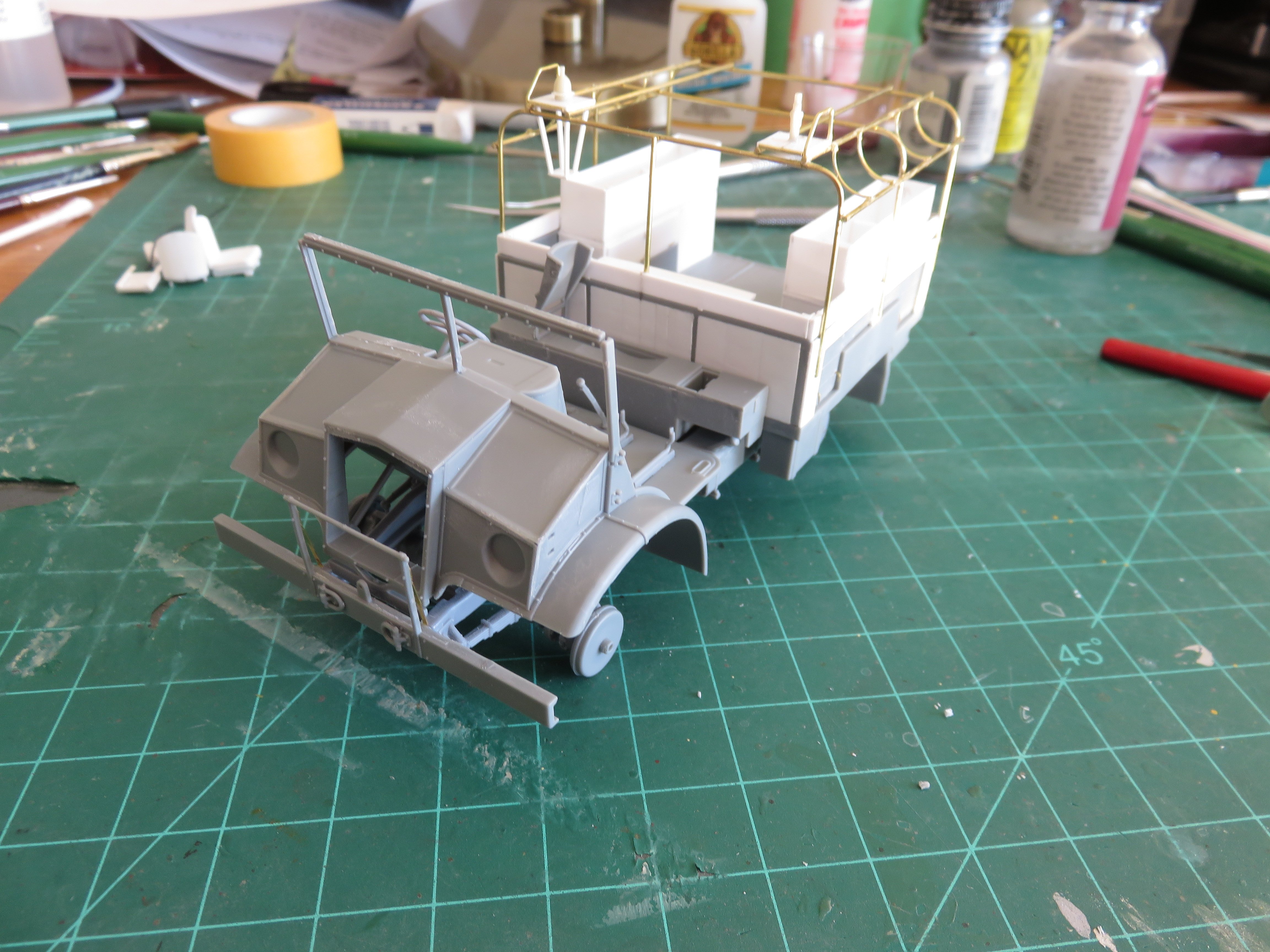
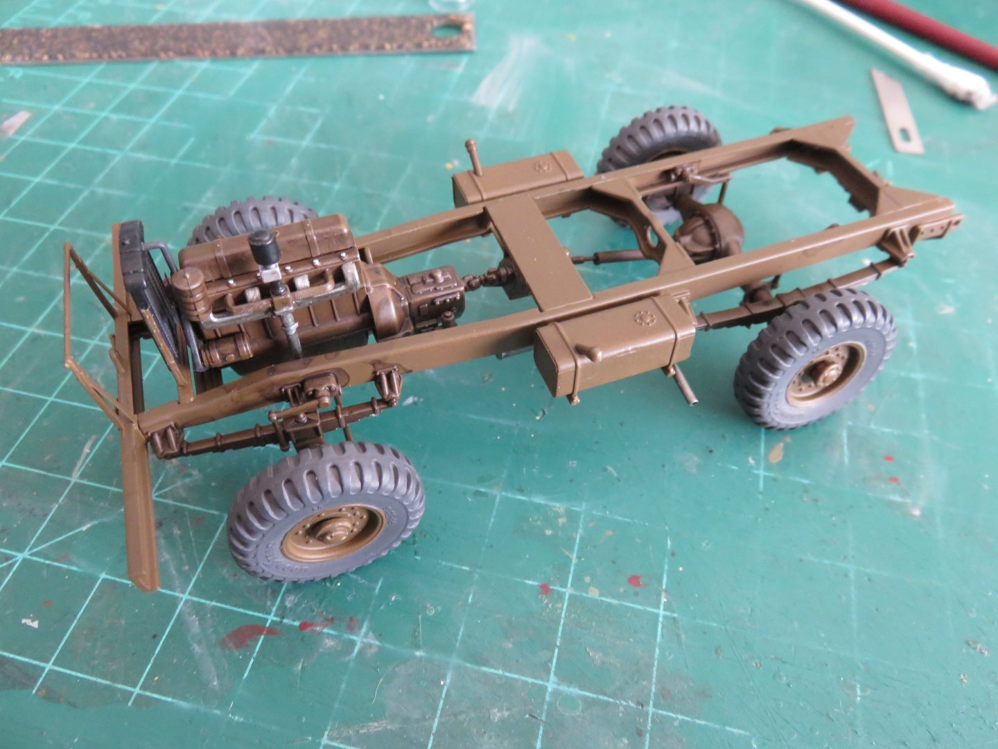
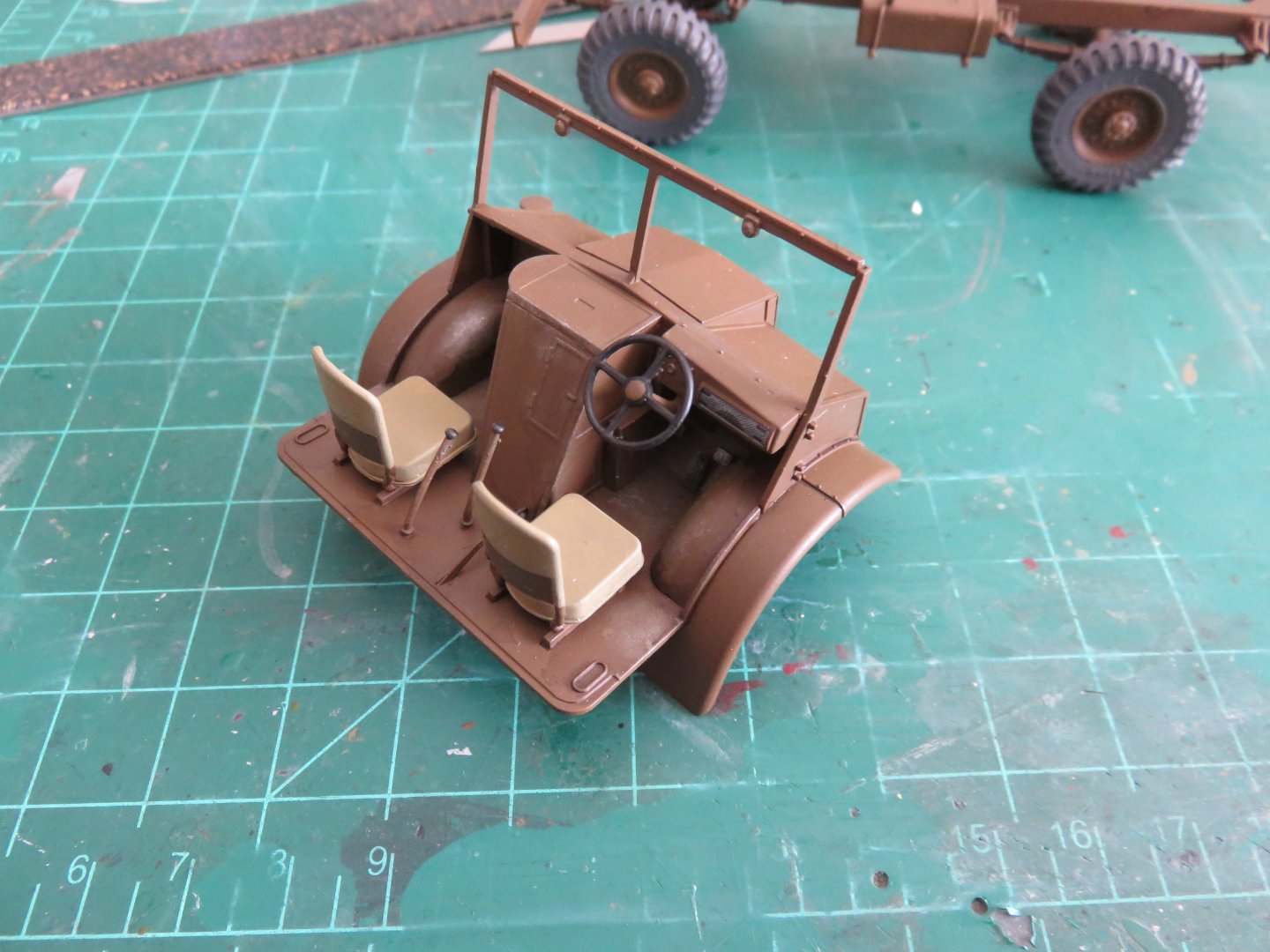
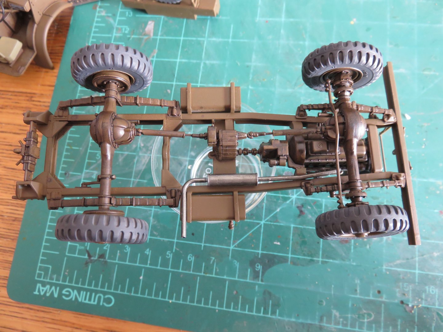
With the approaching holidays, things have slowed down noticeably, but I think I have enough done to qualify for some form of an update. This will likely be the last until after Christmas. Most of the work I've managed lately has been with the chassis. I did, however, get the seats painted and glued in the cab. The seats were not without some small challenges. The cushions were fairly straightforward, but because of accessibility, I had to use CA glue to attache the forward ends to the bases. Regular cement was used at the rear. The seat backs are not held on by very much, just a small scarf joint on the uprights. Annoyingly, even though the frames were all aligned and square (the cushions have a couple of notches that line up with the lower part of the vertical backrest frames), they still ended up being a fraction too wide. It took tome time and faffing about to get the backrests to stay where they were stuck, but they remain fragile. The sooner I can get the cab back and roof on the better (a couple of small things to do yet, and that will happen). As for the chassis, the wheels, engine, radiator and exhaust have now been added: I gave the engine and any mechanical components a black acrylic wash to lend a bit of a greasy, oily look and bring out some of the details. Most of these bits will be hard to see once everything is assembled. The exhaust was another tricky component to add as it lacks any positive locating points. There's only a butt joint where the pipe meets the manifold and a peg on the plate above the muffler (but no corresponding hole in said muffler). To add to all that, the tail pipe slopes downwards from the muffler in order to clear the fuel tank. This is not evident in the installation instructions for the muffler, but it shows up a few steps later. As a bonus feature, I have also drilled out the end of the tailpipe so it actually looks like a tail pipe and not a solid cylinder of plastic poking out from underneath. Finally, since I was on a roll working on the wheels earlier (pun intended), I finished the spare tire mount that sits between the cab and the rear compartment. This was one of those weird "gotcha" parts to build. Everything I'd seen in the instructions, and from what I determined when dry fitting, indicated to me that I had to keep the spare tire separate in order to facilitate painting, as the brackets would not allow the tire to be added if I had glued them on first. Well.... turns out that assumption was very much incorrect. After I painted and assembled everything as per my plan (I didn't glue the spare in, thinking the brackets were enough to hold it in place), I picked up the now completed assembly up by the tire to put it in a safe place, only for the tire to slide ever so smoothly up and out from between the now solidly glued brackets..... facepalm.... Anyway, thanks to everyone who is following along and throwing in the odd "like"! Andy


-
Bentley Blower by RGL - Airfix - 1/12 - PLASTIC
realworkingsailor replied to RGL's topic in Non-ship/categorised builds
All looking great! I’d be careful though, one wrong move and it looks like World War One might break out on that cabinet shelf! 🤪 Andy -
I found one in 1/48 scale here in Canada: https://wheelswingshobbies.com/hph48011r-hph-models-1-48-ship-s-catapult-for-arado-ar-196-pre-owned-10117994/?searchid=0&search_query=Catapult+ Maybe you could use it as a basis for scratch building a scaled up version? Or, conversely, build another Arado in 1/48 scale? Andy
-
A small Saturday update. I've been picking away at some smaller parts the last few days. I've so far managed to get all the resin components of the No 19 radio set sorted out and off their casting blocks. Not much to see yet until after painting and assembly. I've also managed to sort out my dashboard! When I was researching this kit a while ago, I noticed Scalemates had an Eduard PE detail set listed as an aftermarket upgrade. Clicking on the uploaded instructions, Eduard would have you cut out a print of the dash and glue it in place. I simply downloaded the instructions, scaled the dash to the right size on white paper, then printed on some blank decal paper I had kicking around. I painted the pachgound insert with RAF Ocean Grey. In hindsight, I should have gone with a lighter shade, but this will do. At least it now looks like there's something of a speedometer in my truck! I have also begun to add a little wear and tear on the interior surfaces. I first made a mix of RAF dark earth, lightened with a drop of Khaki, thinned to a wash and dry brushed the mix onto various surfaces to represent worn, but not entirely removed paint. This was followed by dry brushing some Humbrol Gunmetal for where the paint may have worn off more completely. I will slowly build up the layers until I am fully satisfied. I plan to follow this with a dark wash to get in the deep recessed areas and bring out some of the details. Anyway, that's about it for now, thanks so much for all the "likes"! Andy
-
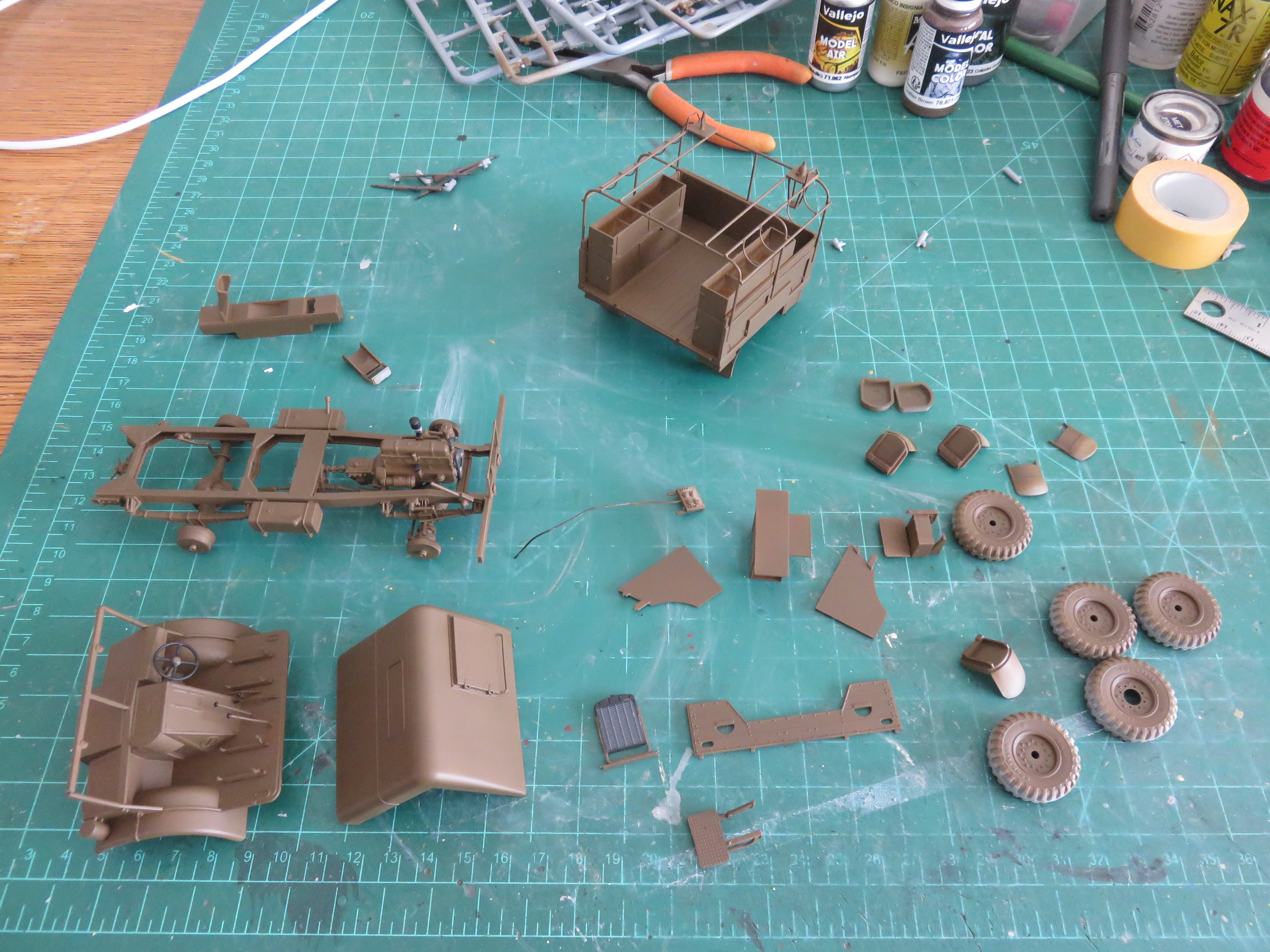
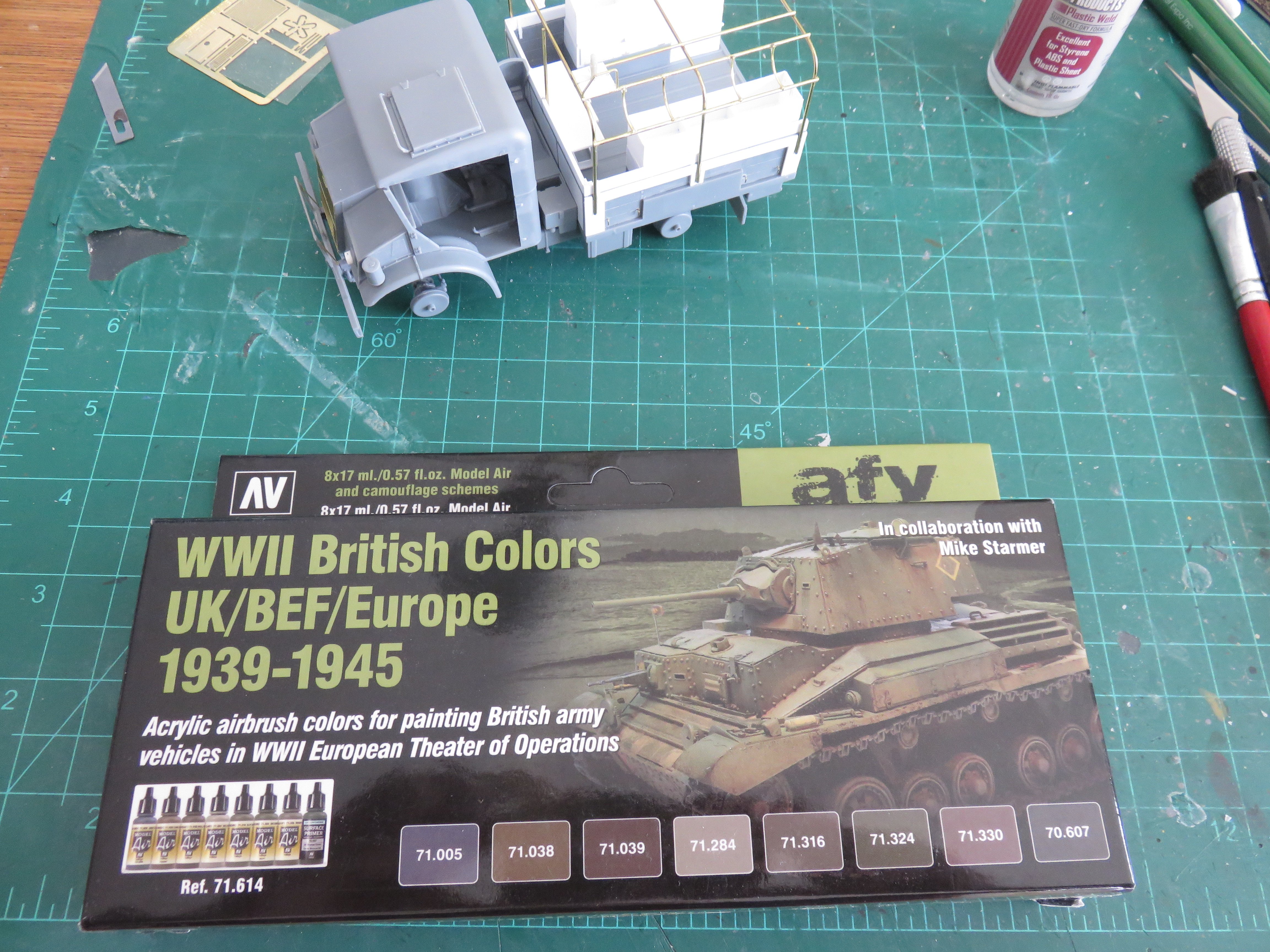
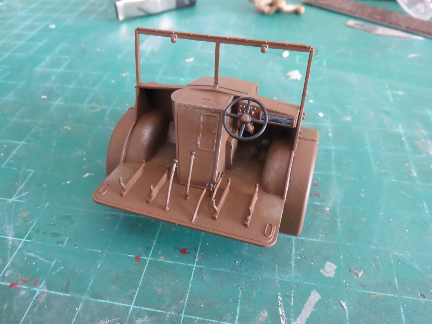
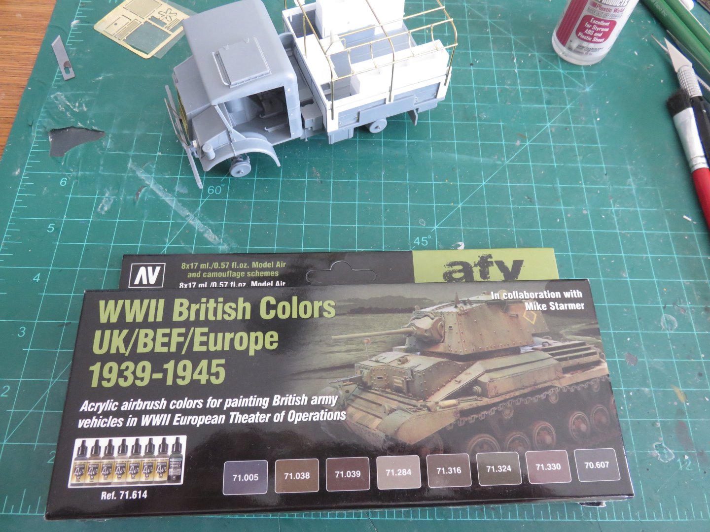
Well, after nearly a week, I have a brown truck.... or at least, an array of brown painted components that might assemble into something vaguely resembling a truck... I wanted to paint my truck in the early to mid war SCC2 brown, rather than the more commonly seen SCC15 OD green. I'm still debating whether to keep it solid brown or add the SCC1a dark brown disruptive pattern. British and Commonwealth vehicles used in the Italian campaign could be found in pretty much every possible British paint scheme, very often at the same time. Often the regiments were so short on time, and replacement vehicles needed so badly at the front, that (re)painting was often neglected. When the 5th Canadian Armoured Division, along with 1st Canadian Army Group Royal Artillery (which included the 2nd Medium Regiment RCA), were sent to Italy in the fall of 1943, they went without any motor transport or armour (no artillery guns, tanks, armoured cars etc). The political wheeling and dealing that brought the balance of 1st Canadian Corps to Italy (1st Canadian Division had been in Italy since Operation Husky, the invasion of Sicily), meant that the Canadians would be taking over the vehicles and guns of the British XXX Corps, who were sent back to England in exchange. This fact was kept secret from the Canadian troops (so as to not dampen moral) by telling them that their vehicles has been lost en-route (a myth helped in no small part by a Luftwaffe air raid that sank two ships and severely damaged a third while the convoy was passing Algeria). Many of the vehicles left behind by XXX Corps were no prizes, however. Many had been in service since the desert campaign, and suffered from many war weary miles. The War diary of the 2nd Medium records an eventful journey in late December 1943 by an advance party in an old Dodge D15 15 cwt truck. The truck had no doors, no brakes, the transmission was missing a gear to two, questionable tires. They had to travers a not insignificant portion of Italy's mountainous terrain in winter. How the men and the old Dodge managed to survive the journey is still unknown. Back to my C15a FFW, Some more test fitting and detail painting has also been carried out. Unfortunately the dashboard is rather lacking in details. Yes there are some buttons and switches, but there's nothing for the speedometer or other indicators that were located in the rectangular panel to the left of the steering column. I will be painting the seats and setbacks in a kind of khaki colour, and after they've been added, I can finish assembling the cab. Just for fun another dry fit of the compontents: I will also need to add a few more small details to the rear area. There were a number of brackets for hanging various small radio components, like the headsets, spare aerial mast sections and even a few rifles. I should be able to make those up fairly quickly and get them added on without too many issues. Thanks, as always, for all the "likes"! Andy


-
Have fun: https://m.youtube.com/@HighwayThruHellCA/featured 😁😁 Looks like they’ve got the first three seasons uploaded, and they’re working on the 4th, plus a bunch of extra. Andy
-
You could do a nice dio with the two trucks… and maybe a trailer looking a little worse for wear, being hauled out of the ditch…. (You haven’t happened to see “Highway Through Hell” on TV have you?) Andy
-
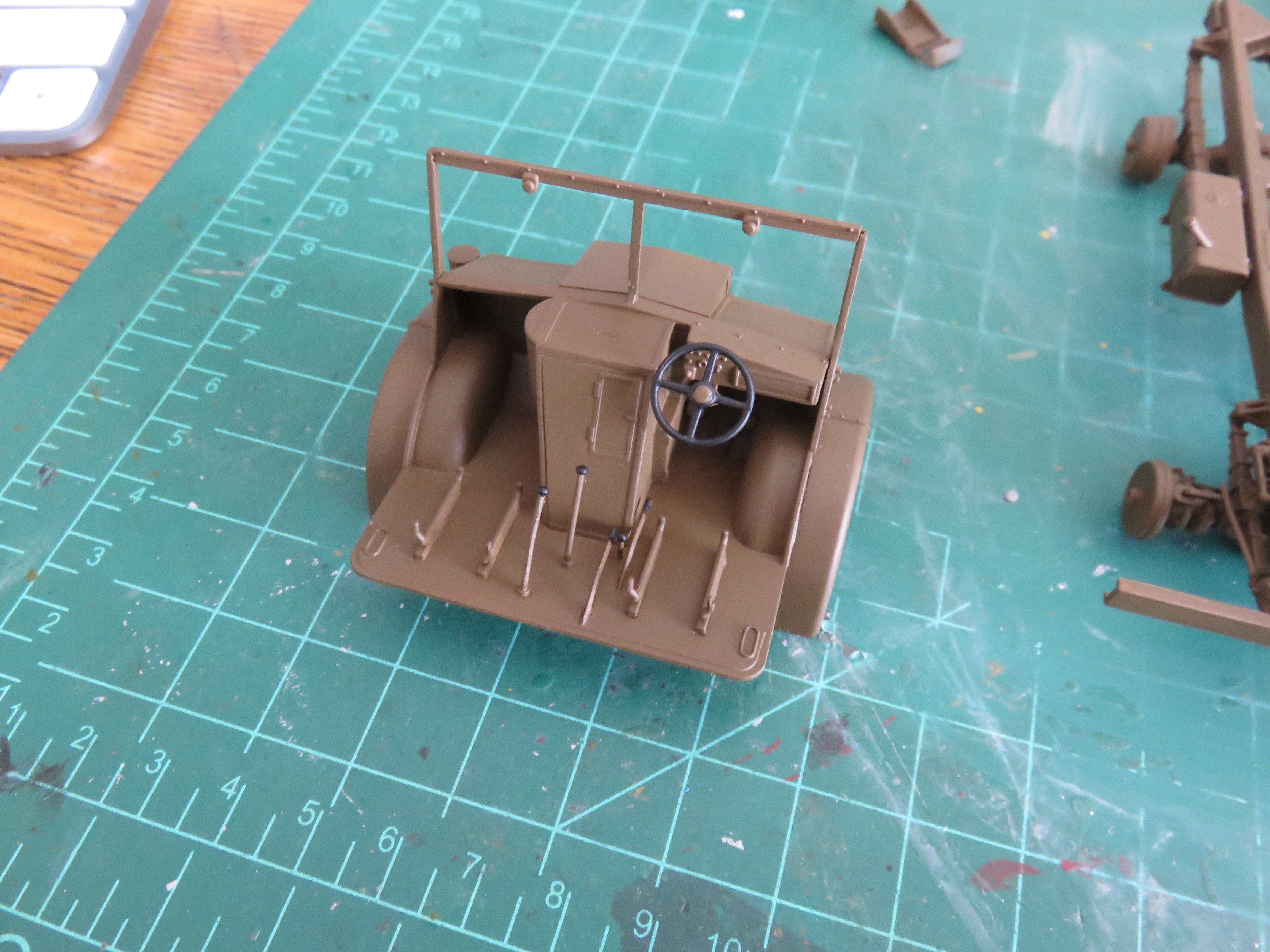
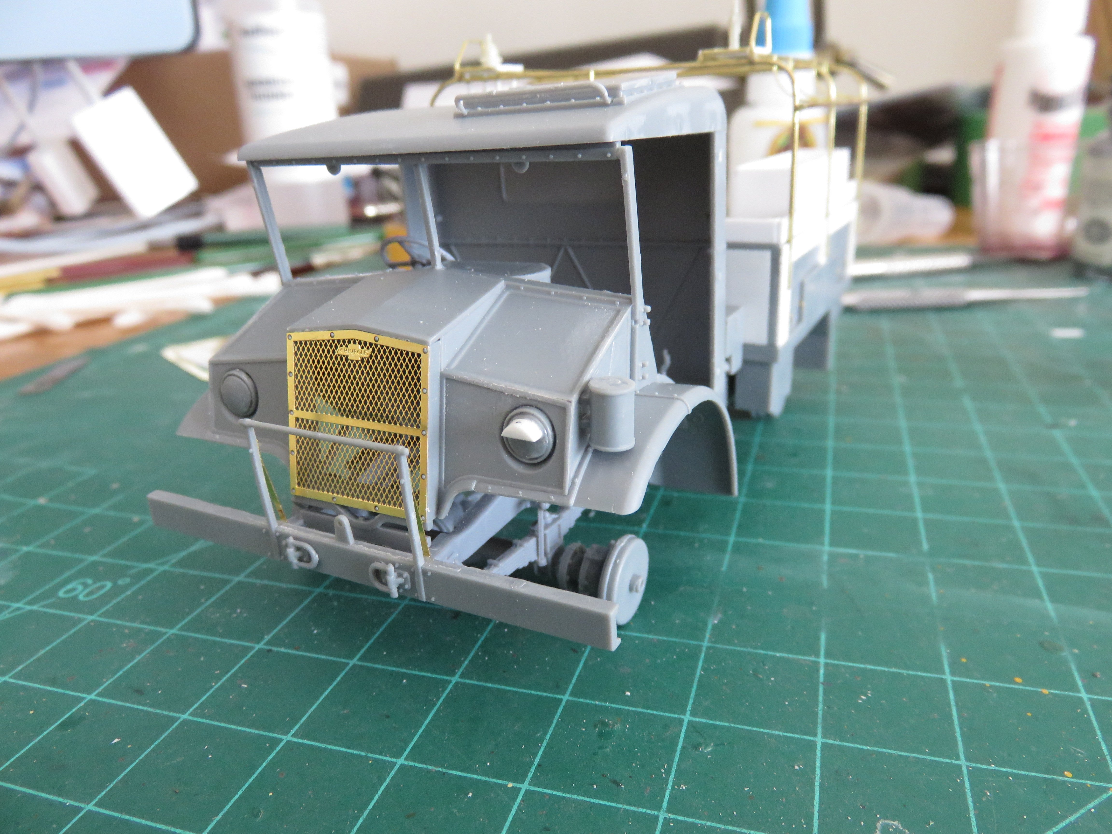
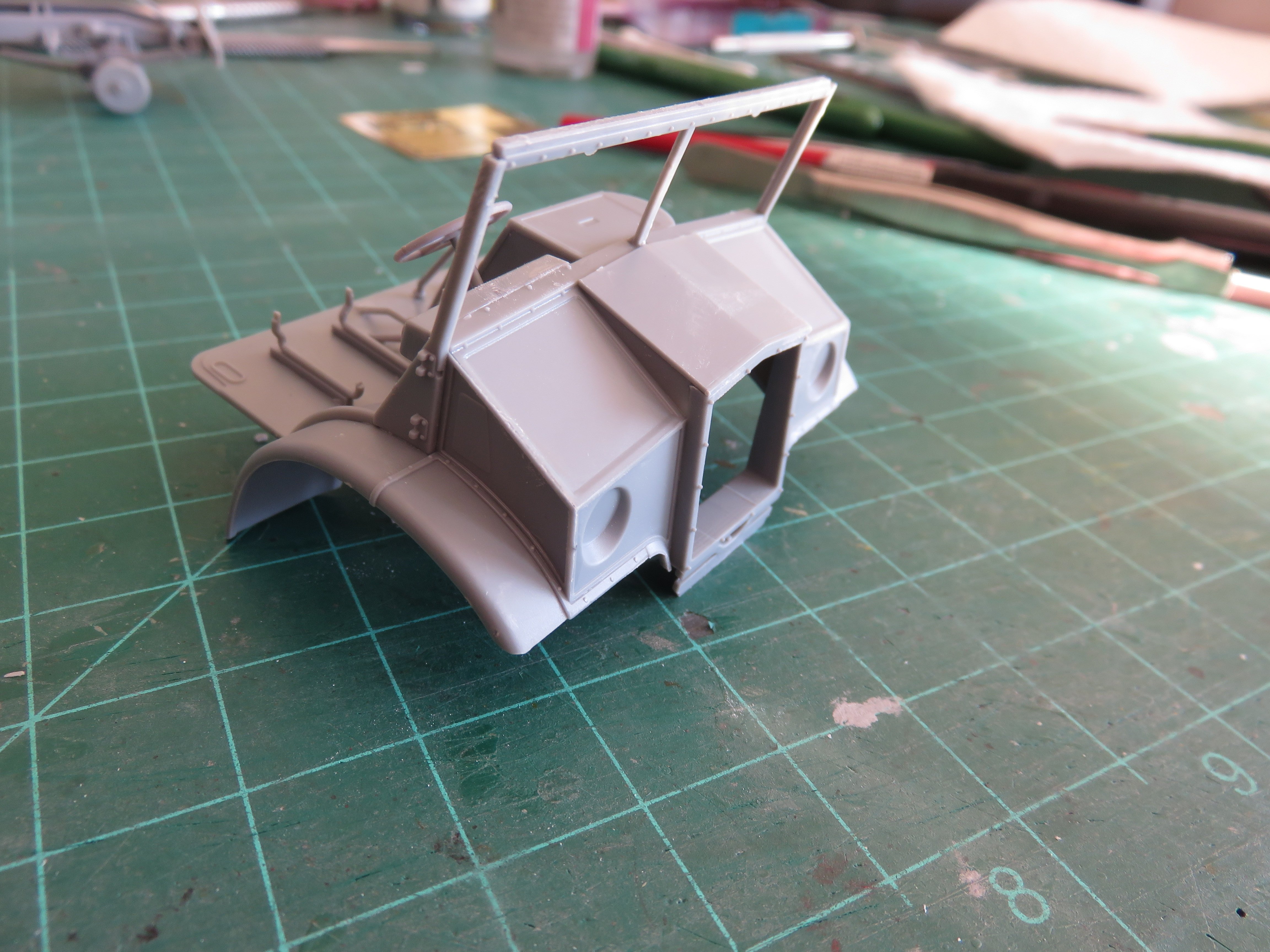
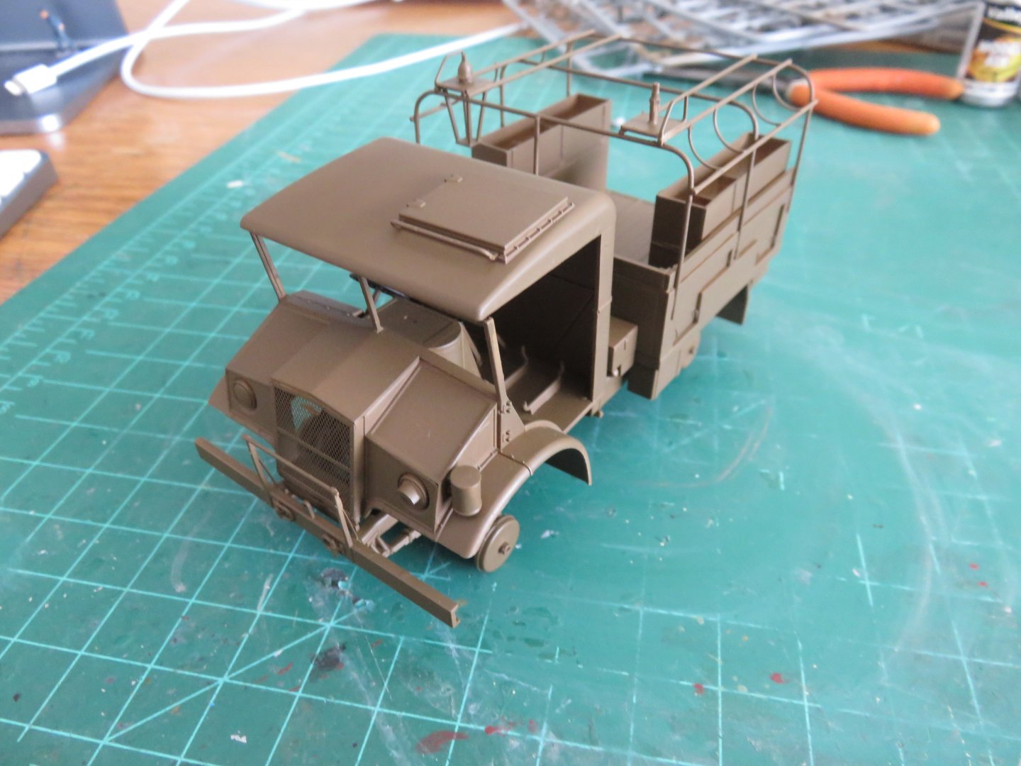
A quick little update for a snowy Thursday morning! A few more components have now been added to the cab: The "headlights" have been added, these consisted of an insert and the blanked lens. IBG seems to have forgotten about the blackout hood that covered the somewhat useable headlight. I made mine out of some styrene rod. Fun fact: while in England, the hooded headlight was on the left hand side of the vehicle, but a couple of days before D-Day, the headlights were swapped so the hooded light was on the right in order to account for the change of roadside the vehicles would be using when on the continent. Interestingly, this change does not appear to have been applied to vehicles operating in Italy. The PE grill fitted perfectly, no issues there. The cab back and roof are glued together, but otherwise just dry fit for now. A little bit more clean-up on the really large sprue attachment points, but otherwise it's really starting to look like a truck! It's nearly time to start getting some paint on this build! I have quite the collection of various parts that will need to be painted separately. Unlike when I build the Tamiya Ford gun tractor, which broke down into only three convenient sub assemblies (not counting wheels and tires!). A bit more planning is needed with this kit! Thanks for all the "likes" Andy


-
Probably not until after the war. Apparently the Mk XIII version of the 9.2” gun was kept in service for home defence, in the south and east of Britain, until 1945. Andy
-
There is a passage in a book by Ian V. Hogg, Barrage: The Guns In Action, (Ballantyne Books, 1970), where he relates an interesting anecdote from the summer of 1940 (summarized): An acquaintance, who in the previous war, had been trained on railway guns, had been dispatched to the coast of England to reconnoiter feasible sites to deploy any of the few remaining railway guns the British army had. Examining a map, he discovered a little valley, adjacent to a main railway line. He set out with a companion to further study the ground. They were surprised when they almost tripped over some rusty old railway spur that led through their chosen valley. Following the disused line, they found it terminated in two old weatherbeaten sheds. Looking between the cracks in the boards, they could just make out some form of machinery. Having decided that this was a prime location to deploy a railway gun, they decided to investigate the machinery in the sheds further. After breaking the lock they found themselves staring at a still gleaming 9.2” railway gun, another was found in the second shed. Alerted to their presence by a suspicious shepherd, the police showed up, along with an elderly pensioner, who happened to be the caretaker of the two railway guns. He had been tending them since they where parked there in 1918, and they were fully serviceable. He had been paid, via the local post office to keep them cleaned and greased and “Bless me, sir, d’you tell me as you didn’t know they was there?” Andy
-
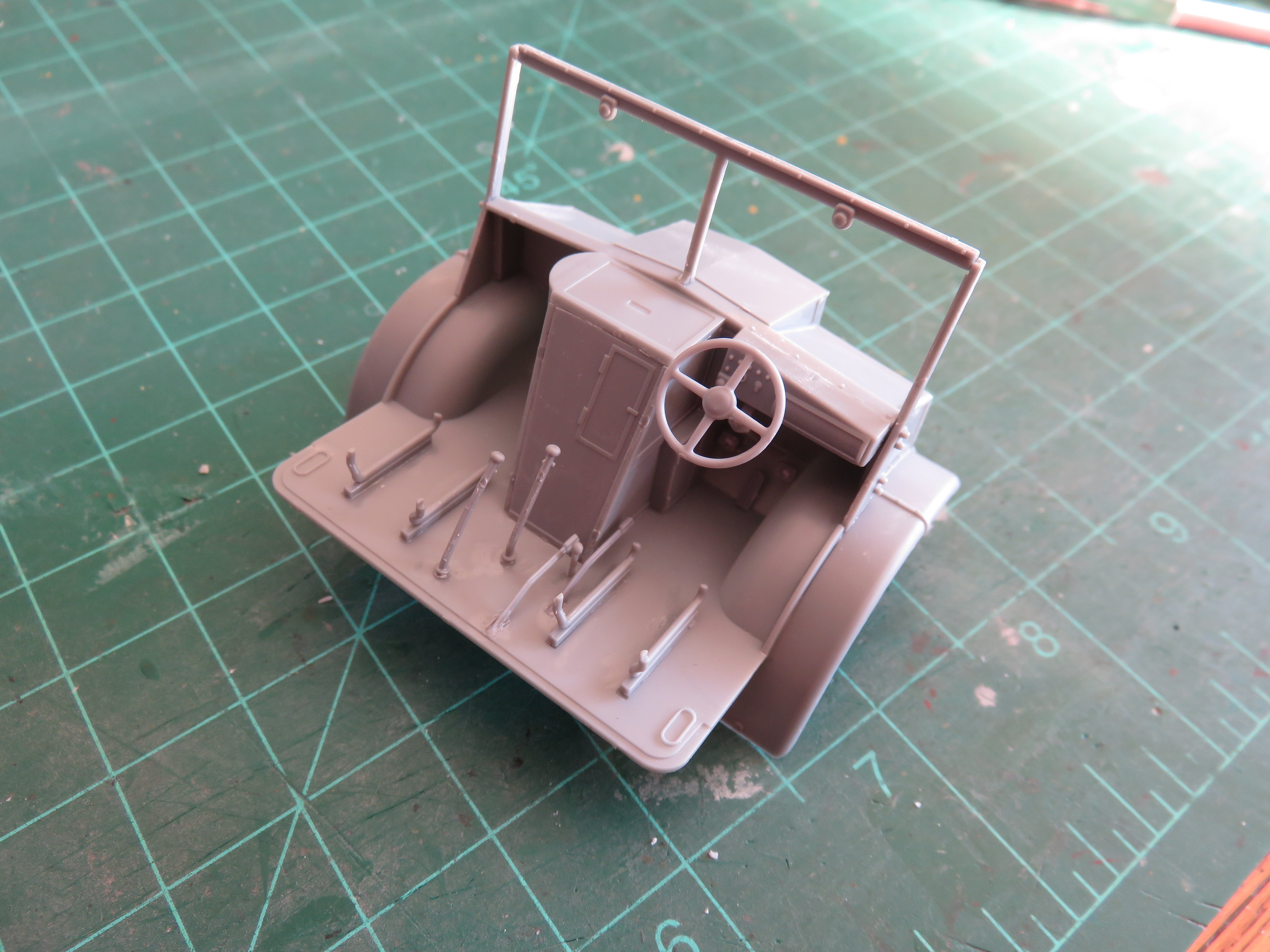
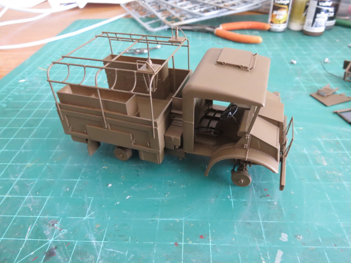
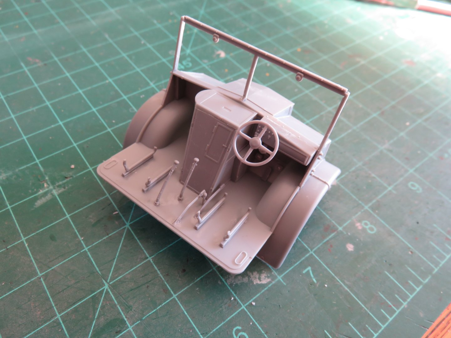
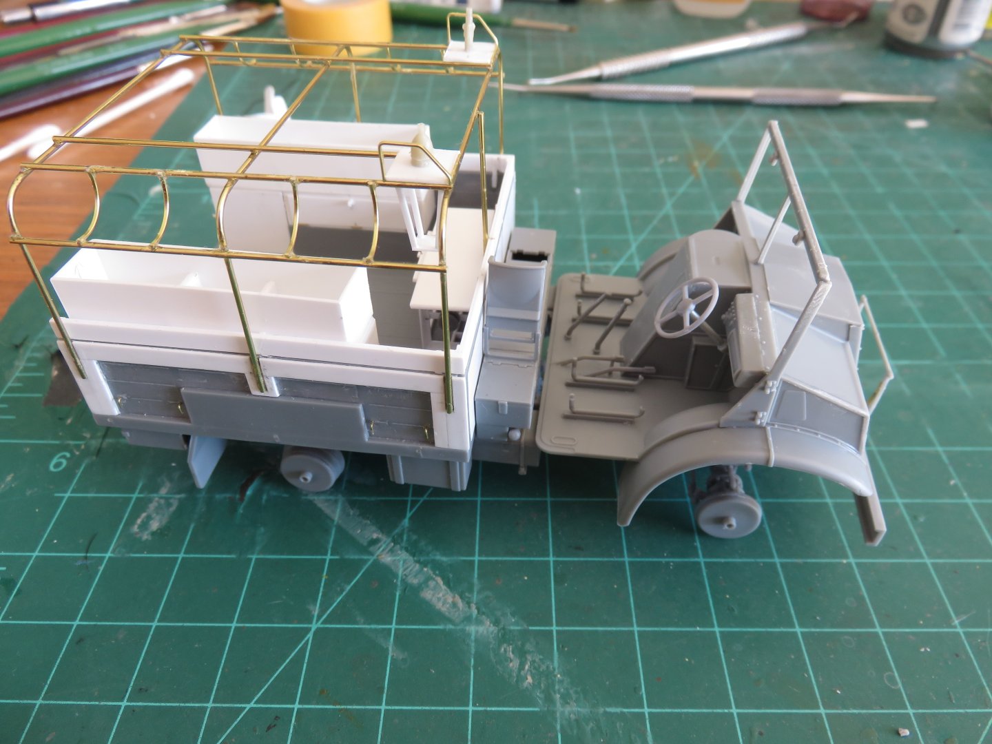
So, it has been nearly a month since I did anything constructive on this build! Waiting for parts.... waiting and waiting.... and waiting..... Well, time to get going again! One thing to note, the IBG kits are definitely not for beginners. There is a very high part count for each step, and the parts are small, fiddly, and need precise cleanup and fitting, or things can go wrong very quickly. The cab assembly I've made up to this point has involved no less than 27 parts (even after leaving a few off to make painting easier)! A good couple of hours work and the familiar pug-nosed profile of the No. 13 cab begins to take shape. So far, I have left off the seats (4 parts), mirrors (four more parts) and fire extinguisher (one part). The grill is PE and I will add that next, followed by the headlights (well, what was left of the headlights after the blackout masking was applied). A word of caution, even though the seat bases are all the same part number, they are mirrored left and right for each seat to accommodate the supports for the seat backs. The rear supports should flare outwards to pass around the seat cushions. For whatever reason, IBG did't give different part numbers. After all the work, I couldn't resist a little dry fitting to see how things look when all the major components I've built so far is brought together: Finally, it's starting to look like a truck! Thanks for all your patience! Hopefully there will be no further parts related delays! Andy


-
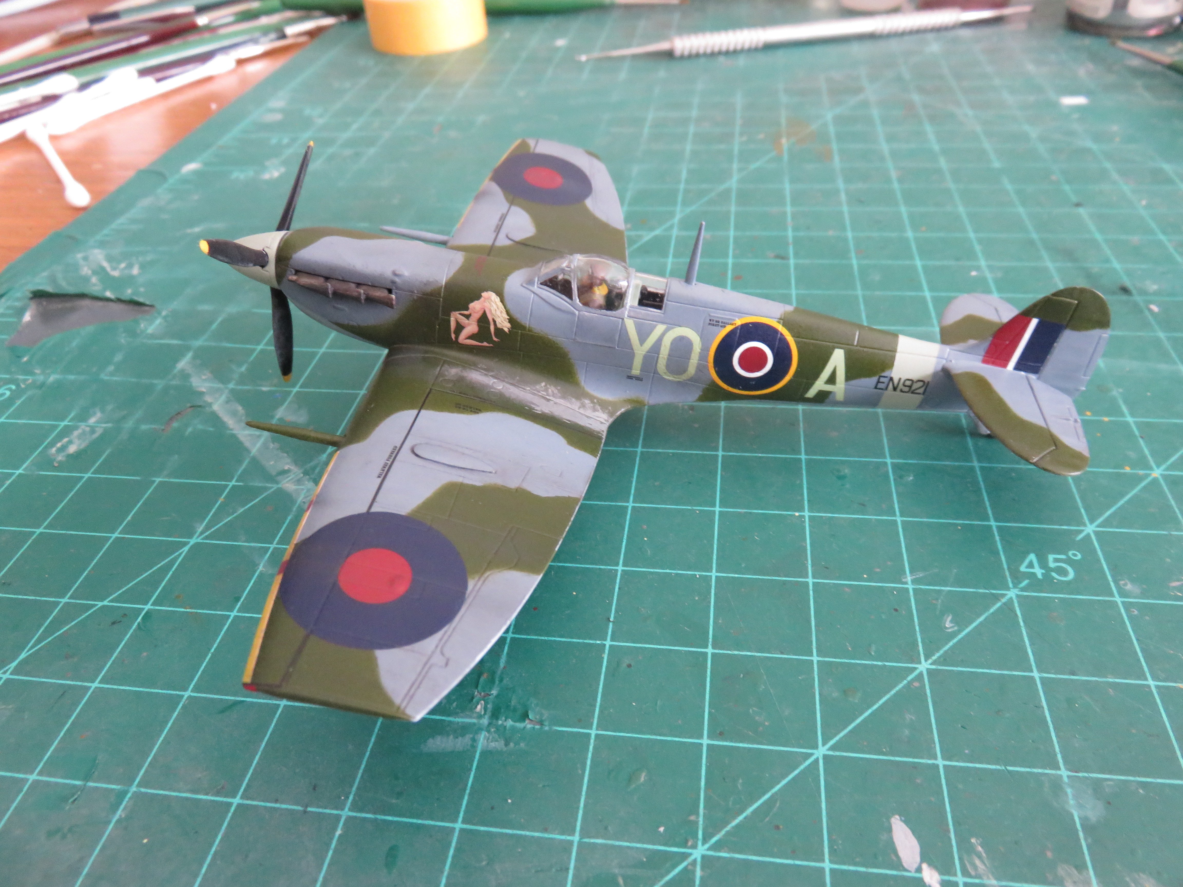
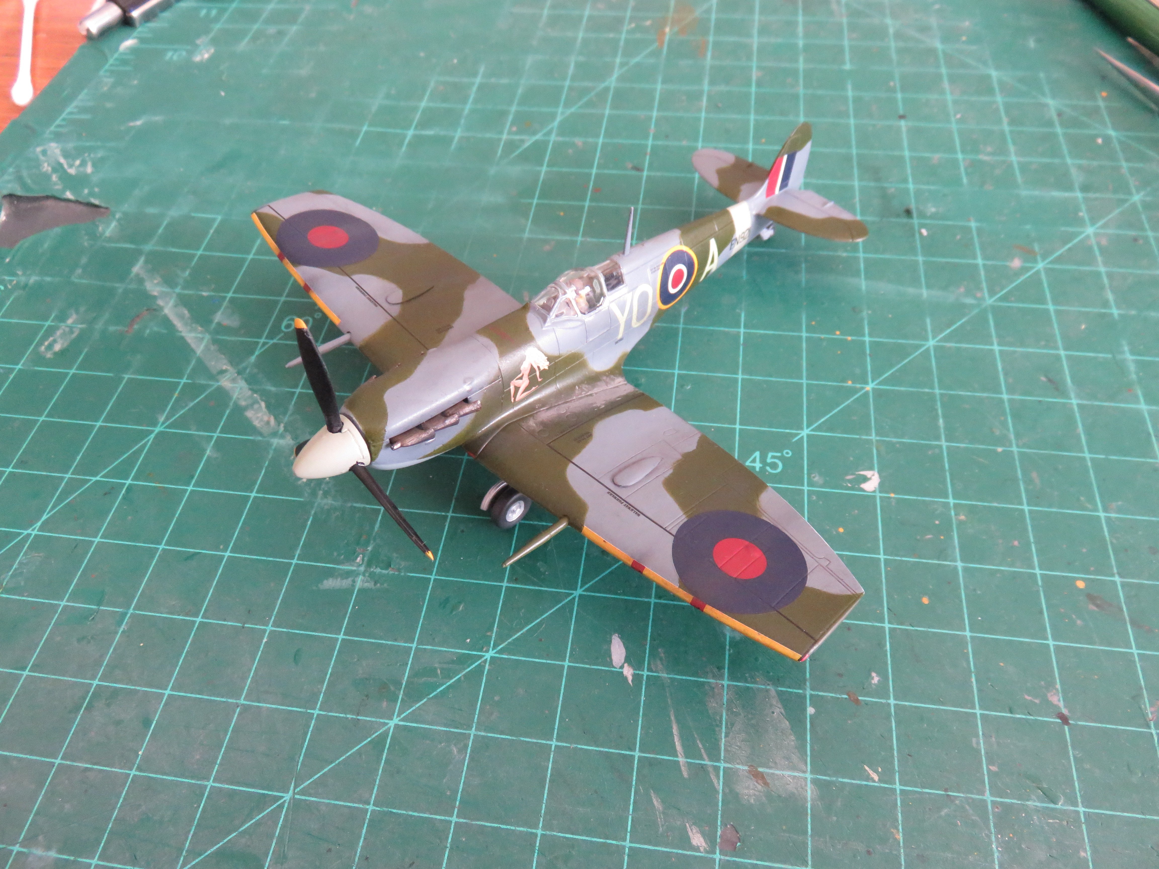
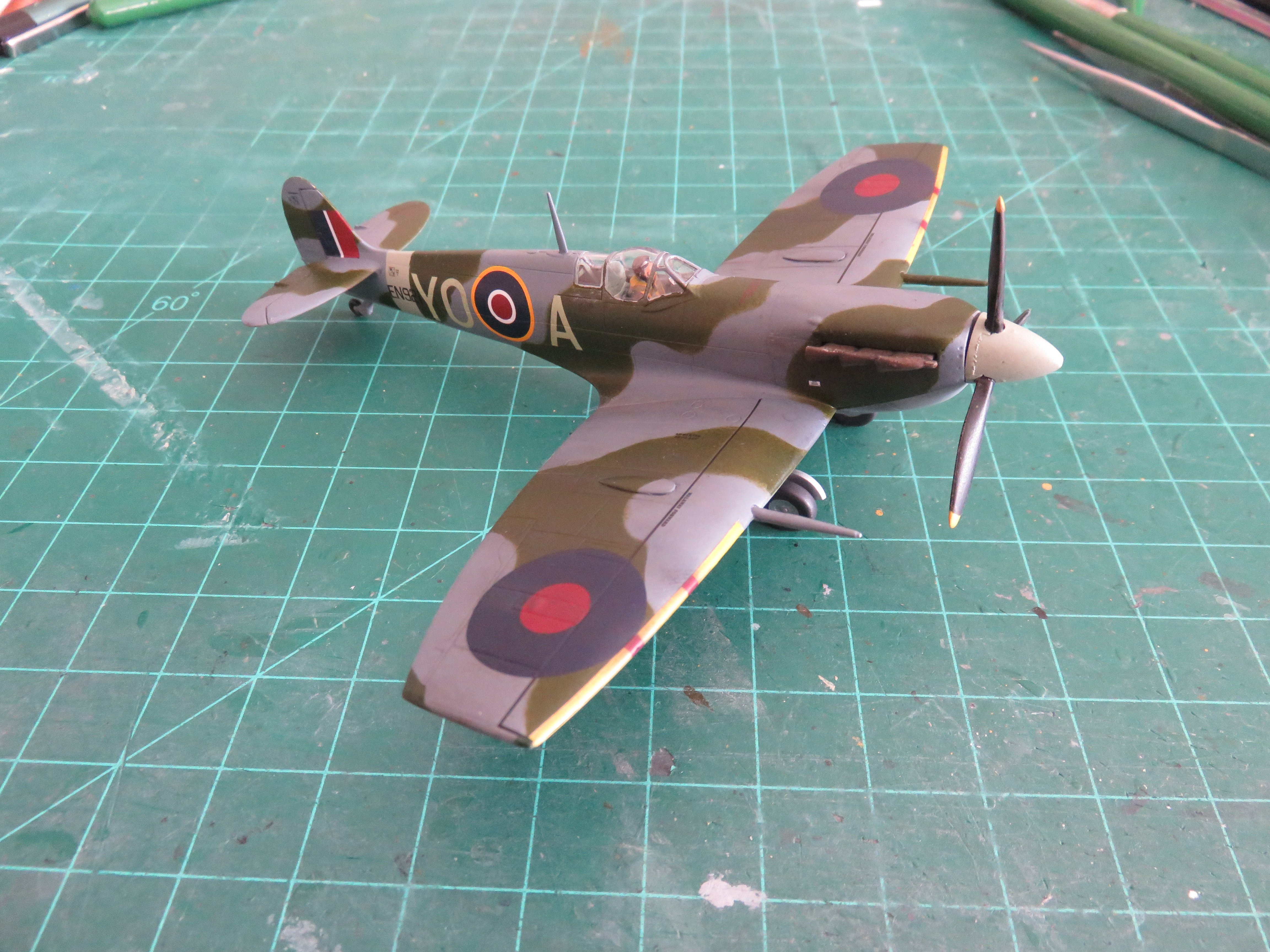
Thanks for all the kind comments and "likes" everyone! I think I'm ready to call this one done! After sealing everything in, I applied a little bit of a wash in some of the panel lines and recessed areas. I then dry brushed on some aluminium colour to add a few more signs of worn paint, especially around the starboard wing root and canopy areas. Finally I did my usual soot and heat staining using pastels applied with a brush and blended. For this plane, I had to go easy on the engine exhaust. From the prototype photos, the lovely lady was reasonably clean, and likely kept that way by the ground crews. Yes, I decided to add the figure in the cockpit. Even had I left the canopy open, there really wouldn't have been much to see, so with the canopy closed, there's a sign of "life". Spitfire EN921 was assigned to 401 Squadron, RCAF, between July and October of 1943. During its time, it wore the code YO-A and was flown by F/O Jack Sheppard. Over the course of the war, he scored 5 confirmed "kills", all FW-190s. The wear on the starboard wing would not have been as heavy as the port side, but there's photos of the ground crew standing there, so some foot traffic should be evident! Overall, this has been an enjoyable, and short little build. As a fairly recent Airfix product, there is an abundance of detail for a 1/72nd scale kit. I encountered no major fit issues beyond what one would reasonably expect for a plastic model. I wouldn't hesitate to recommend this kit to anyone who's interested. A word of note, however; the Kitsworld decal set that I used for the code letters and the nose art appears to be printed, rather than silk screen printed. This means that if you examine the decals closely, there is a grainy-ness to the colours. It's not noticeable from any normal viewing distance, and the decals are still very high quality. Thanks again to everyone who has stopped by and offered their likes and comments (and thanks to those who have simply stopped by)! Looks like I will be returning to my Chevrolet C15a build very soon, see you all there! Andy


- 24 replies
-
- 15
-

-
"Wind of the ball" injuries.
realworkingsailor replied to uss frolick's topic in Nautical/Naval History
Two different things, really; turbulence and pressure waves. Turbulence is the disruption of air as a result of something passing through it. The air can move dramatically in different directions. Yes it can be violent, even modern jets need to be careful of wake turbulence when operating near one another. In your example the asymmetrical action of the turbulence, and the resulting aerodynamic forces acting on a relatively fragile airframe exceeded its structural strength. I very much doubt that the pilot was killed by the turbulence, or even the blast concussion from the fired gun (had he been foolish enough to be flying that close), more likely the abrupt stop when he unexpectedly returned to sea level sans aeroplane. Have a look at the research done by John Stapp in the 40s and 50s (he’s the guy who rode the rocket sled “al fresco”): https://en.wikipedia.org/wiki/John_Stapp Andy -
"Wind of the ball" injuries.
realworkingsailor replied to uss frolick's topic in Nautical/Naval History
I think you can take modern equivalents into account as well. How many WW1, WW2, or even Vietnam war stories involve bullets whizzing by perilously close (and in some cases dinging off) helmets. Or dud artillery shells landing between soldiers’ feet (lots of those stories). All resulting in minimal to no injuries at all (maybe a strong need to change one’s pants). Andy -
After yesterday's excitement of finally receiving the parts I need to continue with my C15 build, I figured it is now a good time to update my progress on here. Decals are now finished, including a plethora of stencils. Admittedly, I didn't include some of the smallest ones, as they tend to look more like specs of dirt than anything. As you can see, I have also added the propellor. (I just had to get the spinny whirly turny bit on!) EN921 had some... uhh..... racy nose art. Maybe a strategy to distract German pilots?? Underneath is grey...... very grey... Next up will be the landing gear, pitot tube and aerial mast, then weathering and finishing touches. Looks like the end is in sight for this one! Thanks, as always, for all the "likes" Andy


- 24 replies
-
- 10
-
-
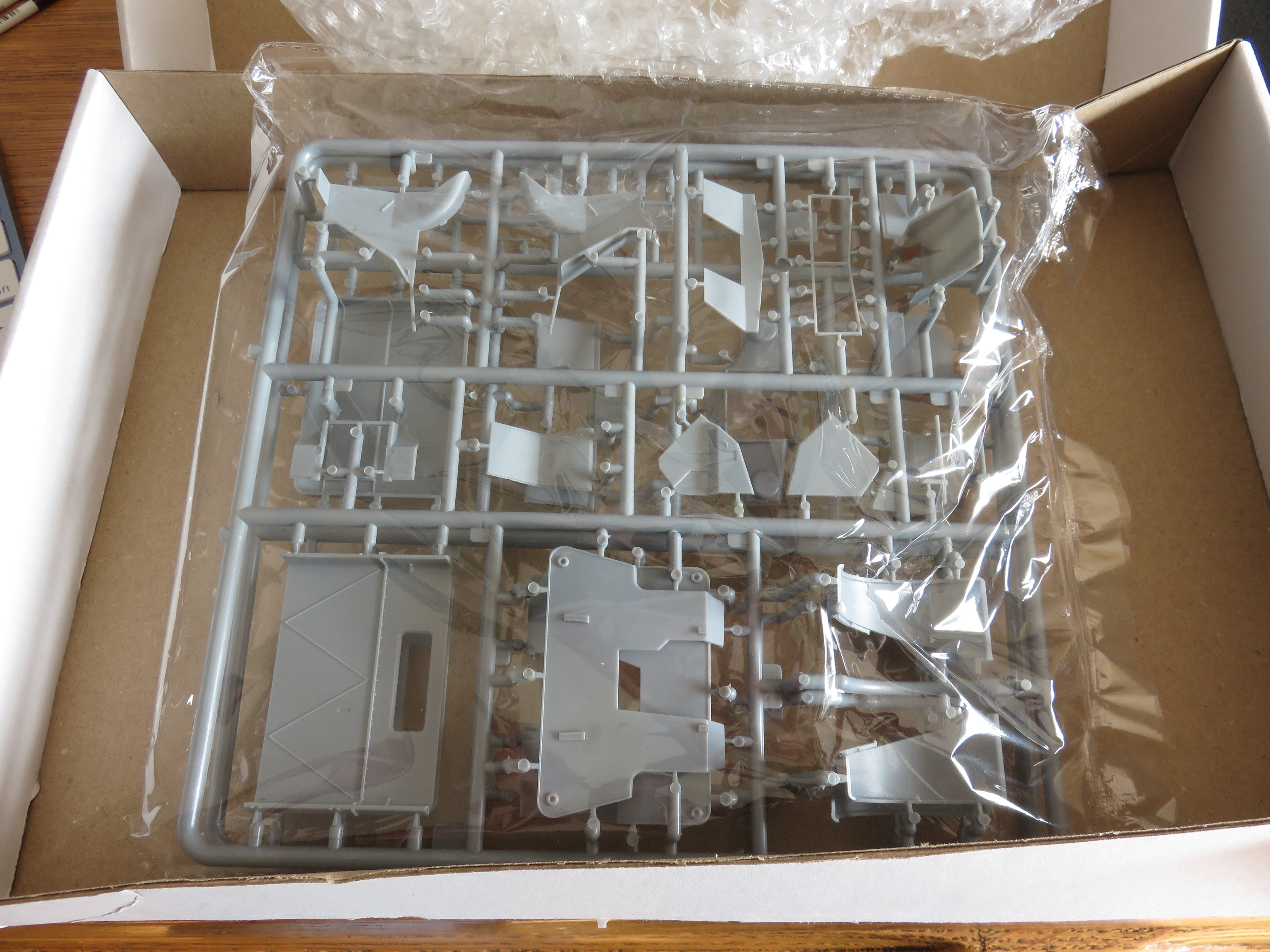
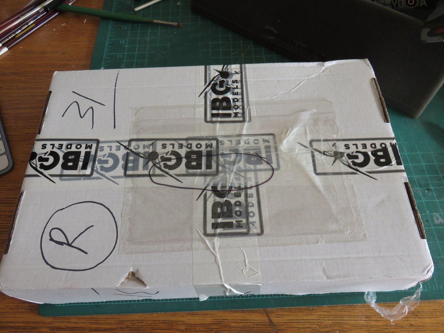
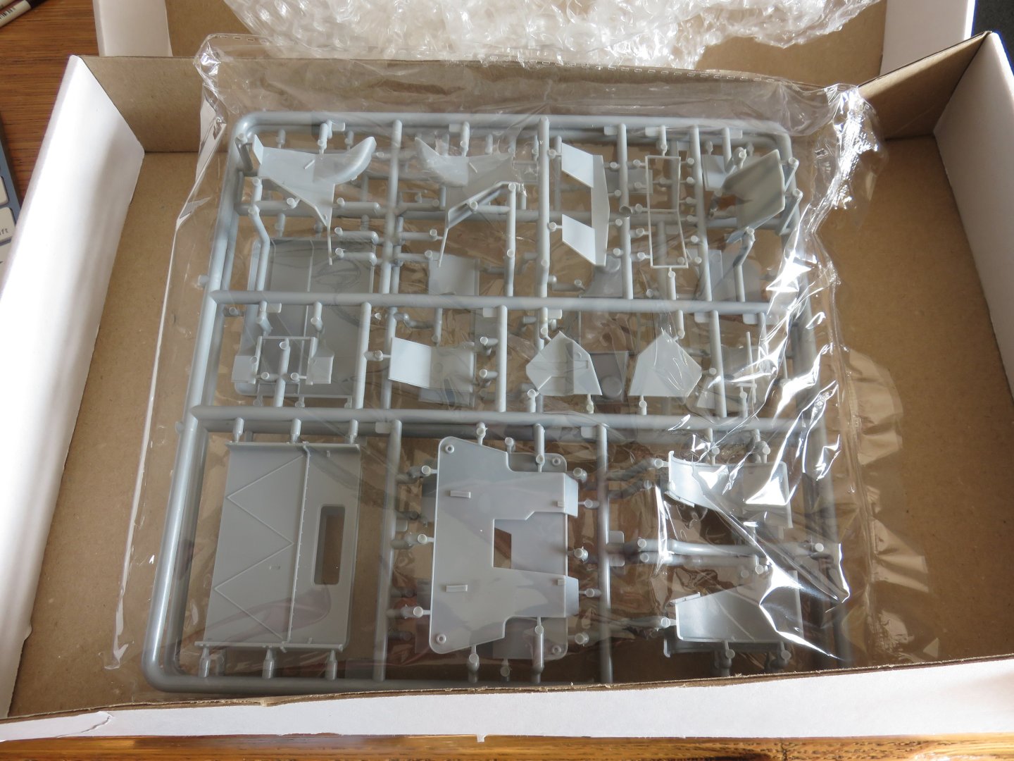
So, something arrived in the mail this afternoon.... it was a larger box than I expected... I mean.... I was only interested in a replacement part..... But IBG sent me two the whole frames that include parts for both cab variants.... wow! And the replacement part I need is in perfect condition! This is so generous of IBG Models! Excellent product support, the only thing needed is a little patience for things to work their way out of Poland. Fantastic! Looks like as soon as I'm done with my Spitfire build, I will be picking up this one again, right where I left off! Andy

-
I did a quick google search, it’s possibly the Seagnat decoy system launchers: https://www.alamy.com/stock-photo-sea-gnat-control-decoy-system-royal-navy-type-23-frigate-28795181.html Andy