tmj
-
Posts
729 -
Joined
-
Last visited
Content Type
Profiles
Forums
Gallery
Events
Everything posted by tmj
-

Gunboat Philadelphia 1776 by tmj
tmj replied to tmj's topic in - Build logs for subjects built 1751 - 1800
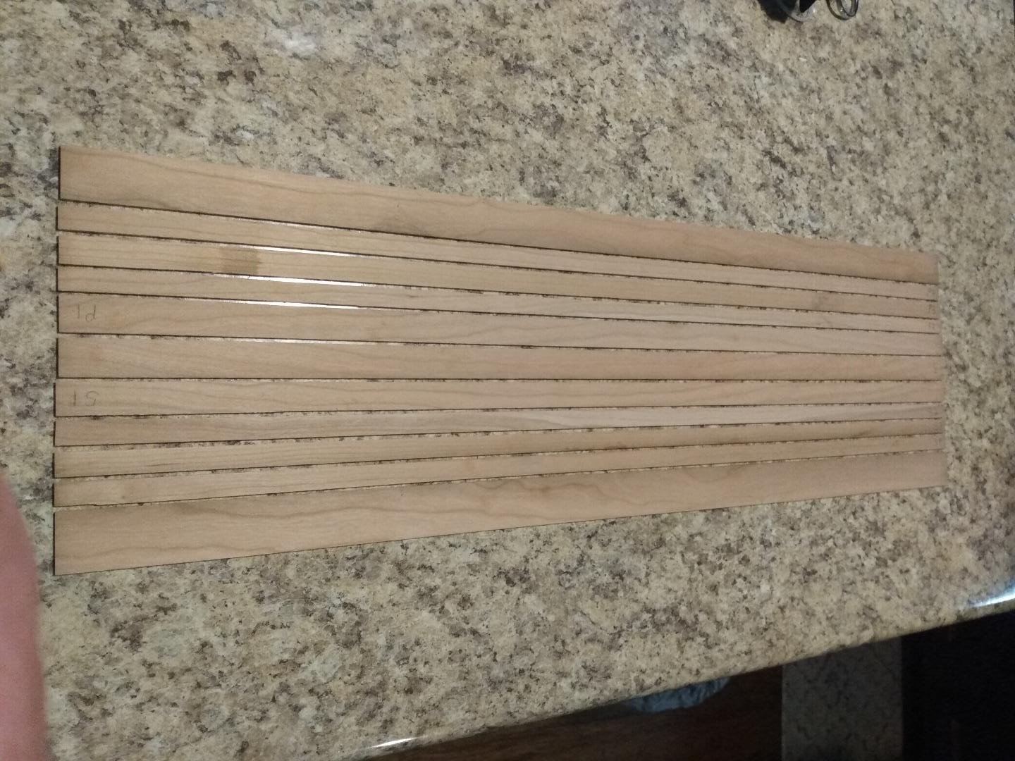
Bottom planking Strakes have all been cut to various widths, as shown in the drawing. I'll clean the edges up and start cutting/separating the strakes into their individual planks while watching Svengoolie tonight. I used my cheap 4" Amazon table saw, steel rules for front and back gauging, and small 'C'-Clamps to hold my gauges in place. I use the calipers to set the cutting width of my pieces. It's kinda 'fiddly' to set up for each cut but works very well and is actually quite accurate for such a 'redneck' rig like this! For today's wood and its thickness, my deviation from measured cut width, during setup, was .017" larger than what I actually wanted. Knowing this, I just adjusted my calipers to read .017" shy of my target width and did my setups to those new dimensions. "Viola!" With a steady feed rate while pushing the wood through the blade I was able to maintain about .005" of accuracy in my cuts. Different woods and different thicknesses will affect the deviation of the cut. I always use a sacrificial "set-up" piece before making any precise cuts, to determine just what the deviation will actually be with that material.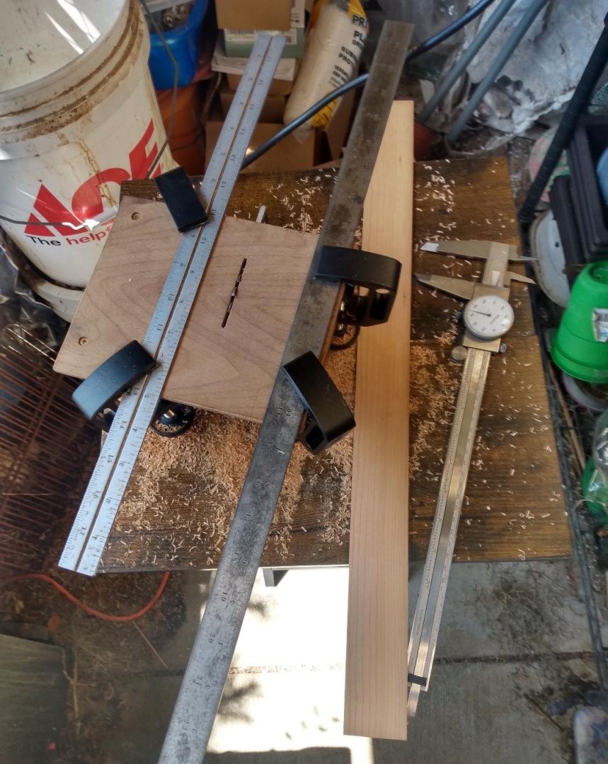
-
Gunboat Philadelphia 1776 by tmj
tmj replied to tmj's topic in - Build logs for subjects built 1751 - 1800
As she was built, the Gunboat Philadelphia was started with the bottom planking being laid down. The flooring timbers were then positioned atop the bottom planking and temporarily 'toenailed' to the bottom planking, just to hold things together, until the bottom planking was effectively attached to the floor timbers via 1" wooden trunnels. Evidence of these temporary toenails are noticeably present on the actual Philidelphia as she sits in the museum today. After the bottom planking and flooring timbers were securely tree nailed together, the temporary toenails were removed, and the bottom was cut to its shape. Some folks wonder if this gunboat was built right side up, or upside down and flipped. The boat was a bit too big and awkward to be flipped. It was built right side up. Evidence of 'this' is due to a 2.75" diameter hole that was drilled through the bottom planking, approximately 48" forward of the sternpost... a hole that was plugged prior to launch. This hole was likely used as a drain to remove rainwater while the boat was being built in its upright position. I hope to have the bottom planking cut and glued this weekend. I'll then cut out the bottom's shape. After that, I'll start on the floor timbers. This is a departure from the actual building process but will make it easier for me to construct in such a small scale, as following posts will explain and further illustrate. -
Gunboat Philadelphia 1776 by tmj
tmj replied to tmj's topic in - Build logs for subjects built 1751 - 1800
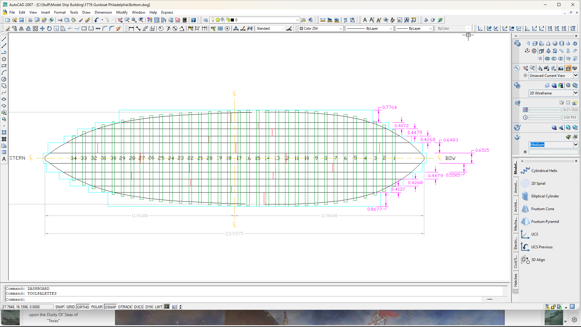
Armed with a few books, a good set of drawings from the Smithsonian, a set of calipers, a calculator and a brand-new box full of wood sheets and misc. sized strips of wood desperately wanting to become something of interest... I hereby declare this new build log as being ready and "Go for Launch!" Please be forewarned. The Gunboat Philadelphia was hastily built, and in such... a lot of traditional practices typically observed in Navel Architecture were not utilized in the construction processes of this vessel, nor in the construction of her seven sisters. Haste was the "Order of the day" and 'time was of the essence'! Corners had to be cut, and 'cut they were'! If you see something that does not seem quite right in my build, well... you are probably correct! I'll be building this model just as its real life counterpart was 'actually' built, not how such a boat really 'should have' been built back in 1776. These gunboats simply were not built in tradition ways, nor were they built to last. They were built solely for a specific and temporary military purpose... and nothing else! I'll be building this as a 'Navy-Board' style model. It will have full masting and rigging with furled sails. I'll also be leaving her sides open to expose the framing, interior structures, etc. Likewise with the decking. I'll be leaving parts of the deck planking off to expose the internals, with exception to the areas supporting the cannons, of course. I don't yet have a clear image as to where this model will actually wind up. I only have a mental concept of the effect that I wish to achieve once all is finally said and done. Below is the current state of my CAD file showing the layout of the bottom of this vessel and the size of the strakes, number of planks per strake, and the positioning of the floor timbers. The red lines on the strakes denote where planks were actually joined to make up the individual strakes. These planks were not joined in the middle of the floor timbers. The floor timbers were too narrow for that due to the 1" diameter treenails used to attach the planks. Instead, the planks were joined together via 1.5" thick 'Butt-Block Splices' located 'between' floor timbers and/or wherever the joints landed, and butt-blocks could be effectively placed. If you look closely, you will also note that the bottom planking strakes are of various widths. Not a lot of consistency at all. I suppose that the builders were just using whatever widths of lumber that they had on hand in order to simply fill in the bottom of the boat. Last but not least... the floor timbers, themselves, 'also' vary in 'their' widths too! Not a lot of consistency there, either. Even though these 'oddities' might look a bit 'off-putting' to some folks, I'm going to do my best to reflect them as they truly are/were in this scale build.
-
1776 Gunboat Philadelphia "Short in life, 'Long' in history!" A Build Log by Thomas J. Painting: "The sinking of the Gunboat Philadelphia"... by Ernest Haas In 1776, the British planned to split the American colonies by advancing south from Canada, via Lake Champlain and the Hudson River. Colonel Benedict Arnold was tasked with delaying that imminent British invasion and recognized the strategic importance of Lake Champlain. Arnold took command of a small flotilla of curious vessels in order to effectively impede that British advancement. Arnold's fleet consisted of 15 vessels, including 8 gunboats. Seeing how this is a 'gunboat' build, I'll exclude mention of the 'other' vessels. The eight gunboats built were named Spitfire, Philadelphia, Congress, Washington, New York, Jersey, Connecticut and Lee. These gunboats were all hastily constructed late during the summer of 1776 in Skenesborough, New York... now known as Whitehall, in a location at the southern end of Lake Champlain. Due to extreme urgency, these gunboats were likely built from green wood. There's also a good chance that no true shipwrights were actively involved in the actual construction of these vessels, evidence being via the unusual manner in which these boats were built. The construction of these gunboats was probably performed by local 'carpenters' who had very little experience as shipwrights, but actually knew quite a lot about building disposable, cheap and effective 'flat bottomed river batteaux's' that were used extensively in the fur trade as well as general cargo transport along the rivers located in that region. This is just logical speculation, of course. Very few records exist. It's difficult to really know for sure. On October 11, 1776, Arnold positioned his fleet in a narrow part of Lake Champlain, near Valcour Island. This positioning was strategic, forcing the British to sail into a confined space where their larger fleet's numerical superiority would be rendered much less effective. The battle began when the British fleet, under General Guy Carleton and commanded by Captain Thomas Pringle encountered Arnold’s fleet. Despite being outnumbered and outgunned, Arnold's forces fought tenaciously. After a day of intense fighting, Arnold's fleet suffered very heavy damage. Recognizing the dire situation, Arnold ordered a nighttime retreat. The Americans effectively managed to slip past the British fleet during the night, but the British weren't fooled, and their pursuit continued. Several of Arnold's vessels were overtaken and destroyed or captured during this battle. The game was over, and the Philadelphia was one of the vessels that was sent to the bottom of Lake Champlain. Arnold soon ran his remaining vessels aground and burned them to prevent them from being captured by the British. This battle delayed the British advance, buying critical time thus allowing the American forces to better prepare their defenses further south. Though the battle of Valcour Island was actually a tactical defeat, Arnold's leadership and the bravery of his men were instrumental in preventing an immediate British invasion of which contributed to the eventual American victory in the Saratoga campaign that took place the following year. Arnold's actions, in 1776, particularly his bold and tenacious defense at the Battle of Valcour Island showcased his initial dedication to the American cause... before his later infamous defection to the British. Today, the Gunboat Philadelphia is noted for its historical significance and is preserved and displayed at the Smithsonian Institution’s National Museum of American History. Its recovery in 1935, along with its conservation efforts have since provided valuable insights into naval warfare and shipbuilding practices, as they were in that region, during the Revolutionary War period. That's the brief history, now... "Let's get on with the build and make some sawdust!"

-
For whatever it is worth, I designed and built a Stainless Steel 10 gallon 'Fire-Tube' steam boiler for my employer this past spring. He wants us to be able to steam bend 1.5" diameter and 2" diameter solid round hardwoods as a new product line for our Architectural construction related business. Nobody else seems to do that, so we'll likely be the first. I've also designed and built a curious steam bending fixture that has adjustable 'false bulkheads' to be used as forms to bend the wood around, after steaming. No need to cut out plywood forms, etc. Just adjust the bulkheads to the proper locations for the radius required and you're ready to bend wood. It's powered by a 9,000-pound winch that folks typically put on their Jeeps and trucks for off-road stuff. 9,000 pounds will allow for much thicker timbers should the boss ever want to steam bend such. Yes, all these woods will be compression bent to prevent splintering and failures. My steam chamber is made from 6" x 6" square stainless-steel tubing that is 14' feet long, with a 1/4" thick wall. Operating pressure is adjustable but expected to be set somewhere around 2psi within the chamber. The heat softens the wood, the steam is only a 'carrier' of that heat. I'm hoping that 2psi of steam will enhance and accelerate the penetration of heat into the timbers requiring less time in the chamber and increasing efficiency and daily production. We'll see if I'm right when all is finally said and done. The chamber hasn't been built yet. Anyway, the attached video is of my initial testing of the boiler system. I needed to ensure that there were no leaks, and also make sure that my math was correct and that I was not accidentally building a potential BOMB! The tests went well, but not without a few nervous moments. The attached video shows the boiler making steam on its first firing. The exhaust hole in the center of the top has some temporary shielding insulating the hot gasses escaping from the boiler stack from coming into direct contact with two redundant emergency pressure relief valves. One relief valve is there to blow if the boiler pressure exceeds 6psi. The second relief valve is there in case the first valve fails, or the pressure builds too rapidly and needs a little extra relief! The boiler has been completed and now has a proper 'chimney'. This video is mostly just an operational test and a leak check. When I actually tested the relief valves, I moved some metal shields in place to protect anyone from shrapnel should the boiler blow up. All went well, but I must admit that I almost pooped my pants when those safety valves finally let go. I was expecting a gentle 'HISSSSSS' that would gradually get louder and louder until it started to get quieter and quieter. That didn't happen at all. Both valves let go, at the same time, with a sudden, unexpected, thunderous ROAR that was deafening! "Scared me half to death, as well as half of the factory employees!" Too bad that I didn't video 'that' one, huh! Anyway... now you know one of the reasons why I find your build log and your steam engine build so very interesting! 🙂
-
It doesn't get much better than this! "Fantastic work and a wonderful project this is!" Viewing this build log, and the videos, could easily send me down a very interesting 'rabbit-hole', or two... and possibly get me into a lot of trouble with my wallet and the Mrs.!
-
Chairs! Let’s see your chairs.
tmj replied to Desertanimal's topic in Modeling tools and Workshop Equipment
I don't use a chair. Chairs are a bit too comfortable, (I could easily sit in a comfortable chair all day long)! I don't need a backrest because I'm always leaning forward, over my workbench. I also do not need arm rests, as my arms are always elevated and resting on my workbench, somewhere. This is what I use. A simple stool. It rolls easily in any direction that I need, when I need to grab something that is just a wee bit out of reach. It also starts to dig into my butt after I've been sitting on it for too long, forcing me to get up off my old 'bee-hind' and get the blood flowing in my legs and feet again, whether I like it or not!
-
Ha ha... I'm not going out alone. "I'm taking you with me!" ☺️
-
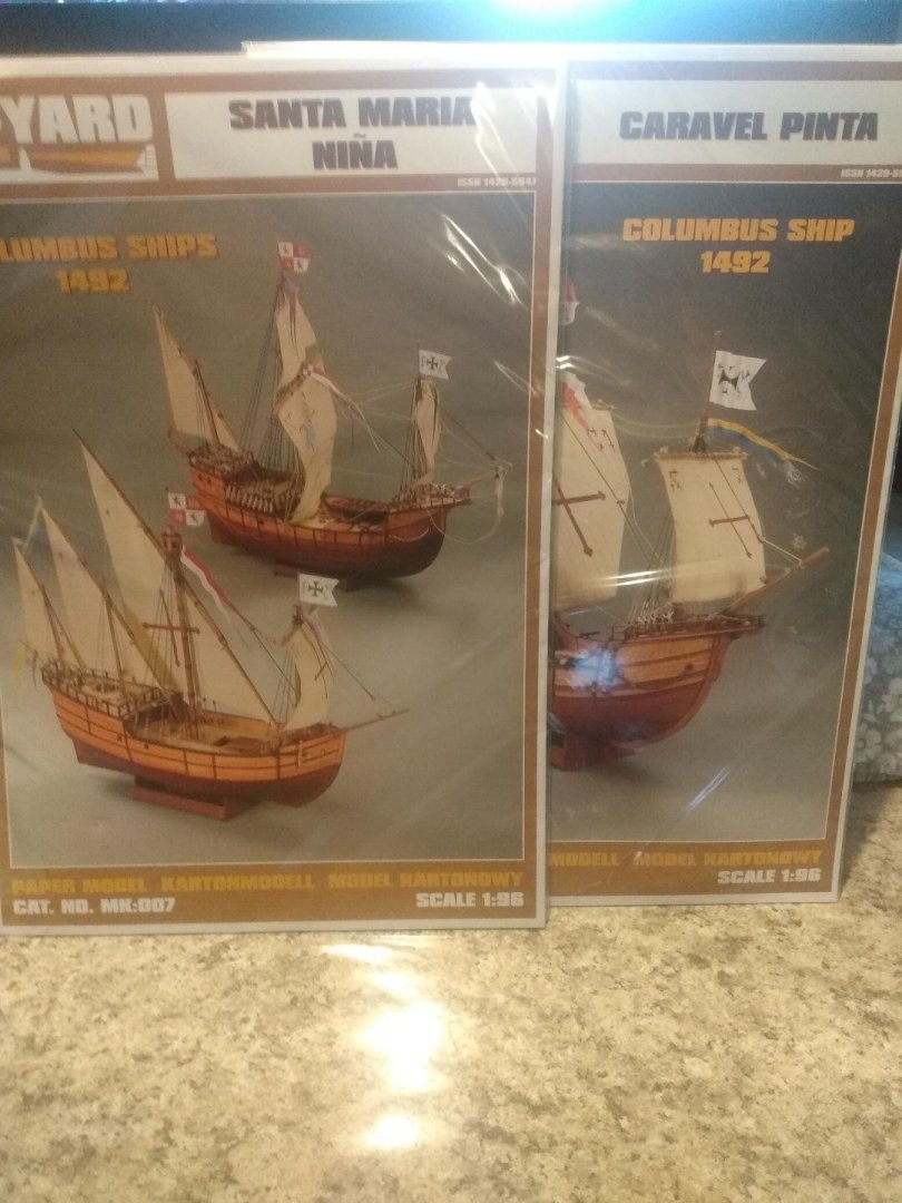
I think that this was ccoyle's fault. I was looking around and accidentally stumbled upon a 'cardstock' build in the forum. Looked kinda interesting so I thought "What the heck!" I went to the named manufacturer, in Poland, and started looking around. Today, an international package arrived containing Shipyard paper model kits for the Nina, the Pinta and the Santa Maria. Not sure when I'll actually start working on these, but 'by-golly' I've got them!
-
You might have trouble finding 'true' Silkspan these days, unless you purchase an old model airplane kit, from the seventies, and rob the Silkspan from the kit. A better alternative might be Esaki, or Gampi Japanese tissue. This stuff will be considerably thinner than Silkspan if scale appearance on a small model is your goal. These thin tissues are used for tiny, indoor flying model airplanes today. Readily available!
-
"Howdy Clive!"
-
Floquill Bright Oil
tmj replied to ulrich's topic in Painting, finishing and weathering products and techniques
Lacquer thinner is what you need. -
Howdy Tony!
-
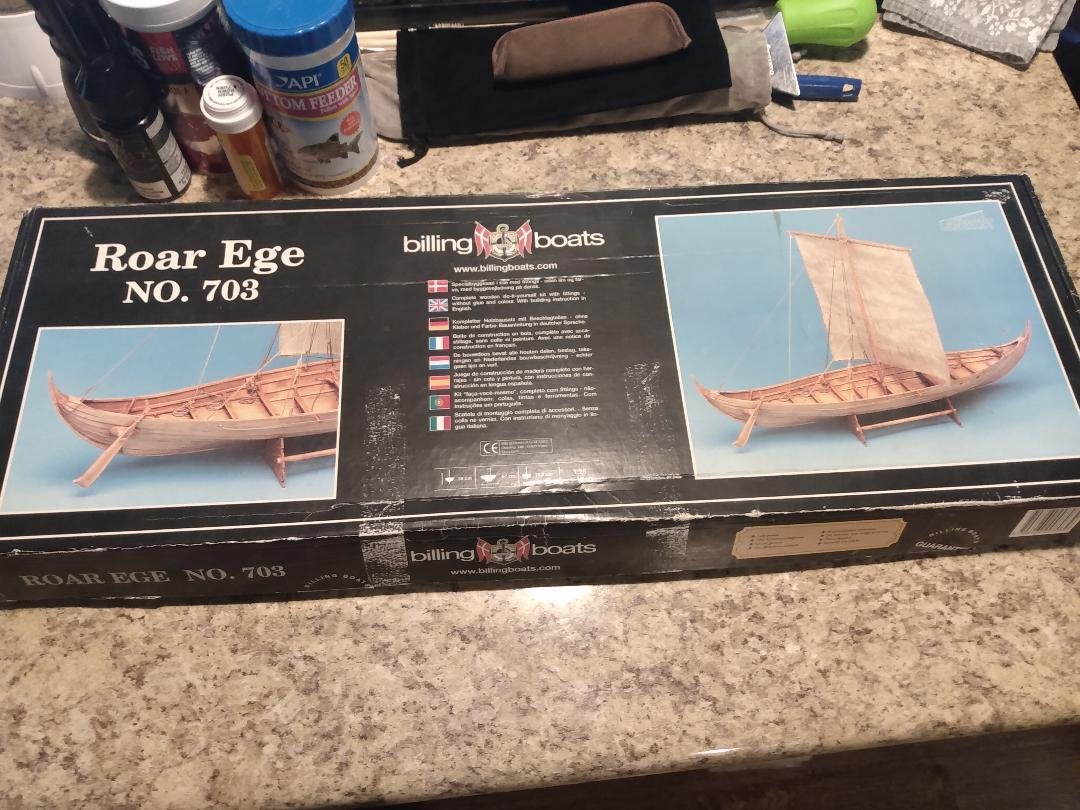
I too will have two Billing's 'Roar Ege's! I have a huge stash of older, un-started kits and got to thinking that maybe I should look through my stash. "Guess what I found?" This was an ebay purchase from sometime a while back. The box looks different than yours, and I won't know what the box of my new one will look like until it arrives. Model-Expo doesn't show the box in their advertisement, only pictures of a built model. If anyone knows when this kit was actually being peddled, please let me know. I'm curious.
- 146 replies
-
- 4
-

-
- Roar Ege
- Billing Boats
- (and 2 more)
-
Scale size questions
tmj replied to Desertanimal's topic in Building, Framing, Planking and plating a ships hull and deck
You are quite correct. The first couple of months, after starting my frame drafts for the Hancock, I was losing my mind on a regular basis. I'd get frustrated, delete my work then start over again, time and time again. I've lost count on how many times I started over with a clean slate. I finally came to the conclusion that I was being a bit too anal about being 100% accurate and started keeping my work and making adjustments as needed, be it truly accurate or not. Maybe my work will be off a few scale inches in length, breadth, and this/that and the other, here and there, but "What the Heck." It became time that I either had to stop trying to be completely accurate and start focusing on just getting things as close as I can, otherwise I'd never finish my design nor begin to actually start building a model. I'll blame this behavior on my 40-year background and career where .005" could mean the difference between "Go, or 'No Go'!" From now on I'll just try to stay as close as I reasonably can and simply focus on a nice-looking design. If something is off a bit, nobody will ever know but 'me'! Okay, I've highjacked this thread for long enough. Time to return it to its original owner... -
Scale size questions
tmj replied to Desertanimal's topic in Building, Framing, Planking and plating a ships hull and deck
Hello David! I have a question that might be beneficial to all parties involved within this topic. Scale rules, calipers, tape measures, CMM machines, lasers... whatever measuring devises one wishes to use. I personally struggle with line thicknesses when trying to take accurate measurements from printed drawings, blueprints, etc. 'especially' when the ink on those drawings varies in thickness, ever so slightly, from one area of the drawing to another. I'm not sure if I should shoot for taking dimensions from the 'perceived' middle of the lines, inside of the lines, or the outer most boundaries of those lines. I like to measure with calipers and then transfer those measured dimensions to CAD drawings, however. When doing this, those slight variations in line width often tend to cause problems with creating smooth geometry within my cad work. I discovered this back when I first started the design work for my 'Hancock' build (still at it, haven't given up, just a slow go). I've found a way to fix this, visually, but in such it always bugs me not knowing if I'm actually pulling the proper dimensions, or not, via my smooth looking visual modifications that correct the once awkward and slightly crooked looking CAD geometry. I know that I'm probably splitting a lot of hairs here, but in such I'm also curious as to just how one should best approach taking accurate dimensions from hand drafted drawings without encountering errors due to line width variations? -
Scale size questions
tmj replied to Desertanimal's topic in Building, Framing, Planking and plating a ships hull and deck
I personally never use fractions, ever... only decimals even with the metric system. Fractions are sloppy, 4 place decimals are extremely accurate. -
Scale size questions
tmj replied to Desertanimal's topic in Building, Framing, Planking and plating a ships hull and deck
You need to know the actual size of the real subject that you are modeling in scale. In your case, if I understand your question properly, 1:12 means that every part you make should be 1/12th the size of the real subject's part. For example, if you wanted to know how long a 100-foot-long item would be if modeled at 1:12 scale you would simply divide 100 by 12. The length would be 8.3333 feet in length. -
Micha, I'm a bit behind on your build but will be catching up. I hope that you were able to resolve the problem. For whatever it is worth, this sort of thing is where PVA glue sometimes shines. PVA can be softened with heat from an iron and parts can often be 'taken apart' if bad things happen.
- 146 replies
-
- 2
-
-
- Roar Ege
- Billing Boats
- (and 2 more)
-
Micha, I've been eyeballing this model for quite some time. I think I'll build this model with you! I just ordered mine from Model Expo. It should be here Friday, maybe Saturday. 🙂
- 146 replies
-
- 4
-
-
- Roar Ege
- Billing Boats
- (and 2 more)
-
Don't be afraid of that Grand Banks Dory! You should have no trouble, at all, building that model. It should prove to be a great transition from plastic to wood. You'll likely find out that a lot of your previous plastic models were probably more difficult to build than this Dory will be! 🙂 "Don't Fear the Wood!" "Welcome aboard!"
-
Roger, How do you 'diffuse' the light so that you do not have bright "HOT-SPOTS" where the lights are mounted? I tried making one of these for a gal at work and could never get the light the way we wanted it. If I mounted the lights around the perimeter of the box, with a wide border to hide the lights, the face of the box would be brightest around the outside of the 'window', getting darker as you moved towards the center. If I put the lights in the middle of the window It looked like a box full of light sabers through the diffusion material. Even tried LED strips for a more subtle effect, but still no go. No matter what I tried, I could always see where the lights were. I never achieved a smooth, uniform lighting effect.
-
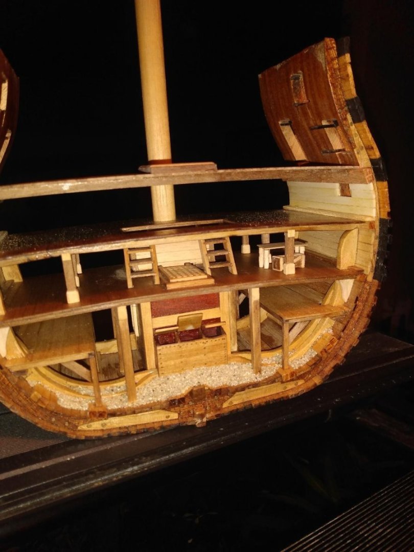
I finally got around to building a table and a crate for the Orlop deck. I'll probably make one more of each for the port side of the deck.
-
Drafting Frames
tmj replied to tmj's topic in Building, Framing, Planking and plating a ships hull and deck
Thanks Mark. Unfortunately, the ship in question is the Continental Frigate 'Hancock' (captured) aka the 'Iris'. There doesn't seem to be much data out there, for this vessel, other than RMG's plans.