


tmj
-
Posts
725 -
Joined
-
Last visited
Content Type
Profiles
Forums
Gallery
Events
Everything posted by tmj
-

Gunboat Philadelphia 1776 by tmj
tmj replied to tmj's topic in - Build logs for subjects built 1751 - 1800
Holes look crisp and the color of the trunnels is good, however. Bamboo won't work for my trunnels at 1:24 scale. The internal porosity is much too pronounced in a treenail this size. I'll try Birchwood toothpicks and see how 'that' works.
-
Gunboat Philadelphia 1776 by tmj
tmj replied to tmj's topic in - Build logs for subjects built 1751 - 1800
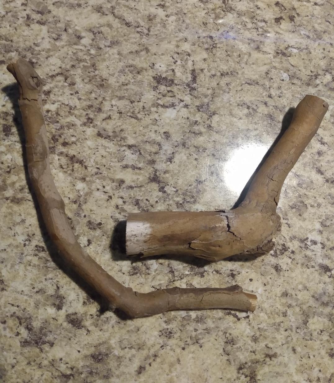
I caught the shop supervisor dumping some personal debris into the company dumpster today. Seasoned branches and twigs from his back yard. He claims it is willow, but I'm not so sure, nor do I care. It has a nice off-white, cream color to it and a very tight grain. I warned him about using the company dumpster for personal use, then asked him to put the rest of the branches in the back of 'my' truck! 😐 What can I say? "One man's garbage, another man's treasure!" He surely thought I was nuts until I told him what I was up to. Anyway. I cut a couple of branches that look about right for the size and shape of my Philadelphia's stem and stern posts. I haven't officially verified their correctness, yet, but I will. If these two cuttings don't work, I'm sure that there are other specimens that will. I simply grabbed two branches off of the top of the pile that looked somewhat promising.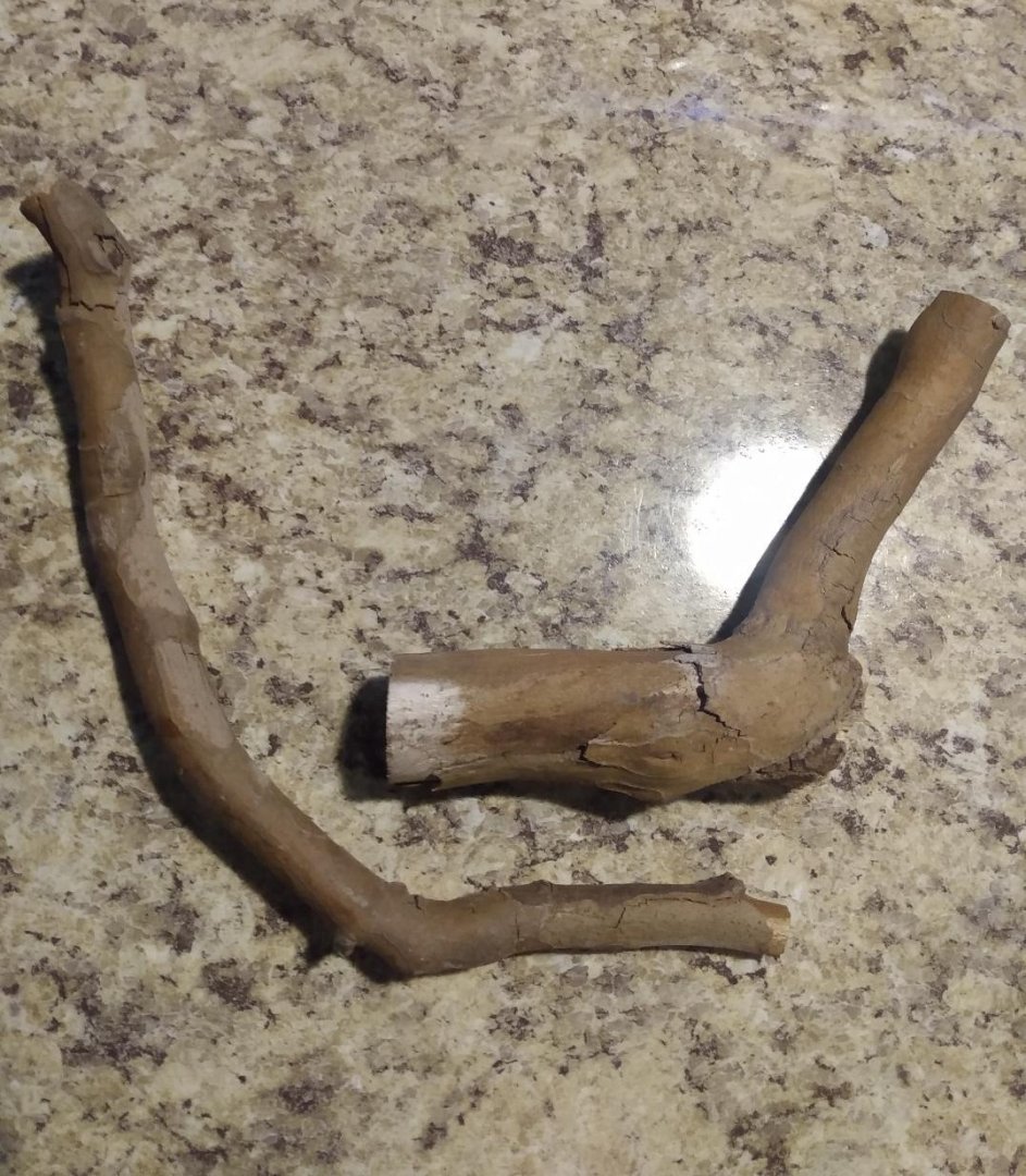
-
Gunboat Philadelphia 1776 by tmj
tmj replied to tmj's topic in - Build logs for subjects built 1751 - 1800
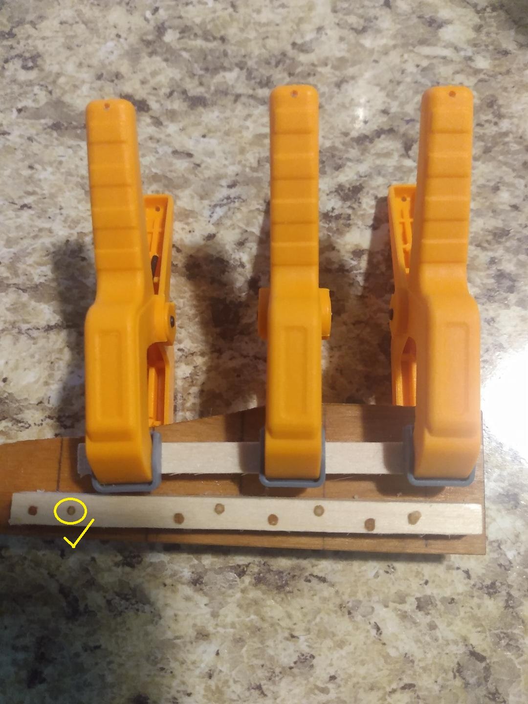
I made good progress on both Basswood 'and' Bamboo trunnels today. I've made maybe enough trunnels to do 1/3d of the boats bottom and flooring timbers. I'm trunneled out for the day. Time for a break! Before getting too carried away, I want to do another test to ensure that the colors of the trunnels 'and' my drilling crispness is truly where I want them both to be. There's still a lot that could go wrong, as you can see by the sloppy holes from my first test. It took me 8 tries to get the speed and feed of my drill-bit correct via that first attempt. I'm now just letting glue dry to get ready for the next test. Fingers are crossed!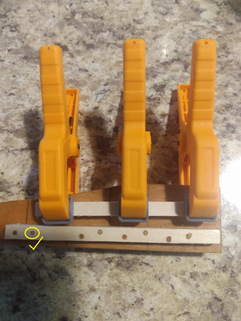
-
I'm really liking this project of yours! It's different and quite nice. If I start building an old wooden oil derrick, or windmill... "It's YOUR fault!"
-
Gunboat Philadelphia 1776 by tmj
tmj replied to tmj's topic in - Build logs for subjects built 1751 - 1800
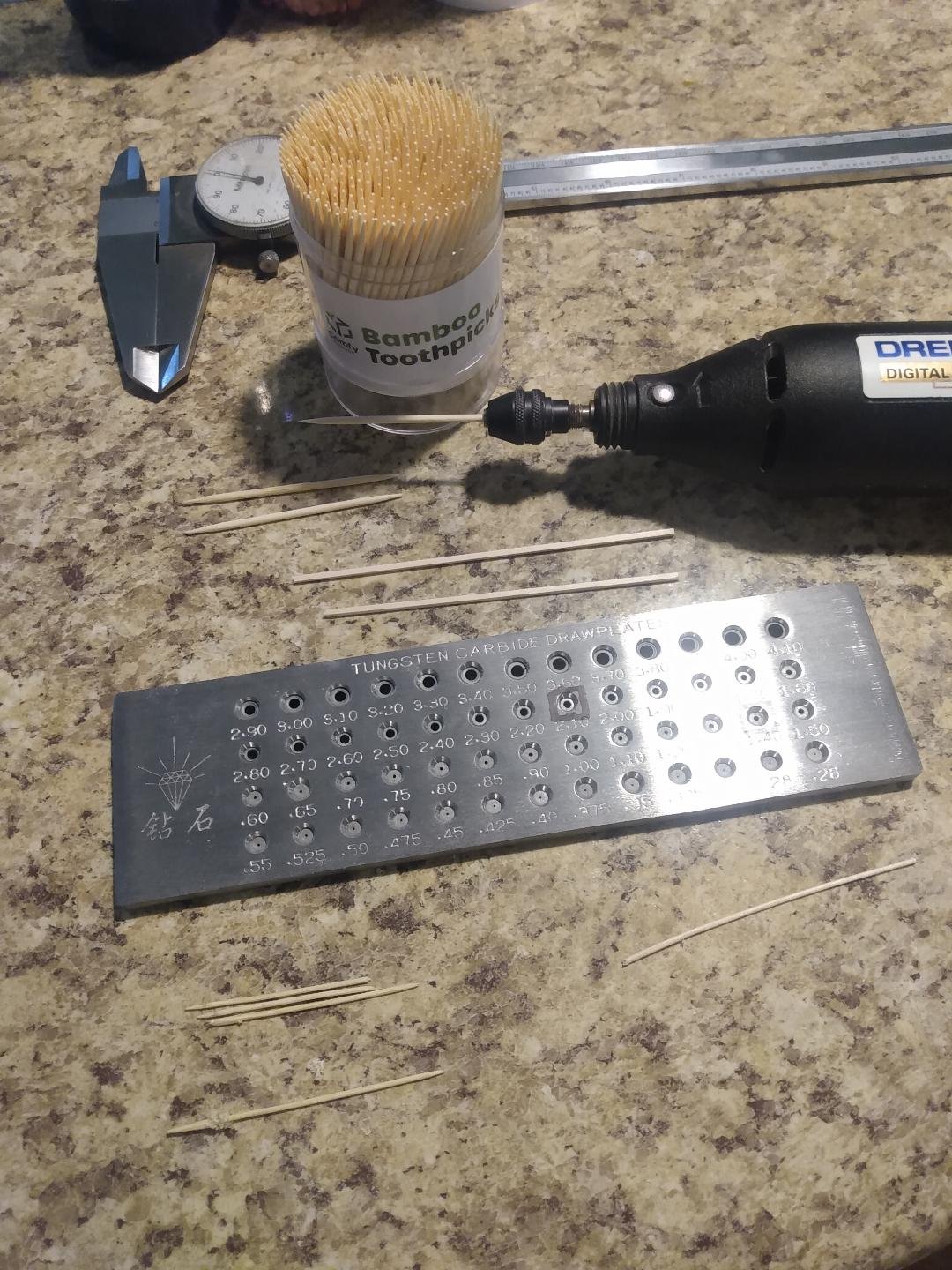
I thought I'd try using a rotary tool with my drawplate. It actually works on both round toothpicks as well as 1/16" square stock. The round toothpicks are Bamboo, and the square stock is Basswood. I can't go more than 4" long on the square stock otherwise it starts to wobble wildly at my Dremel's lowest setting. So far this is working great!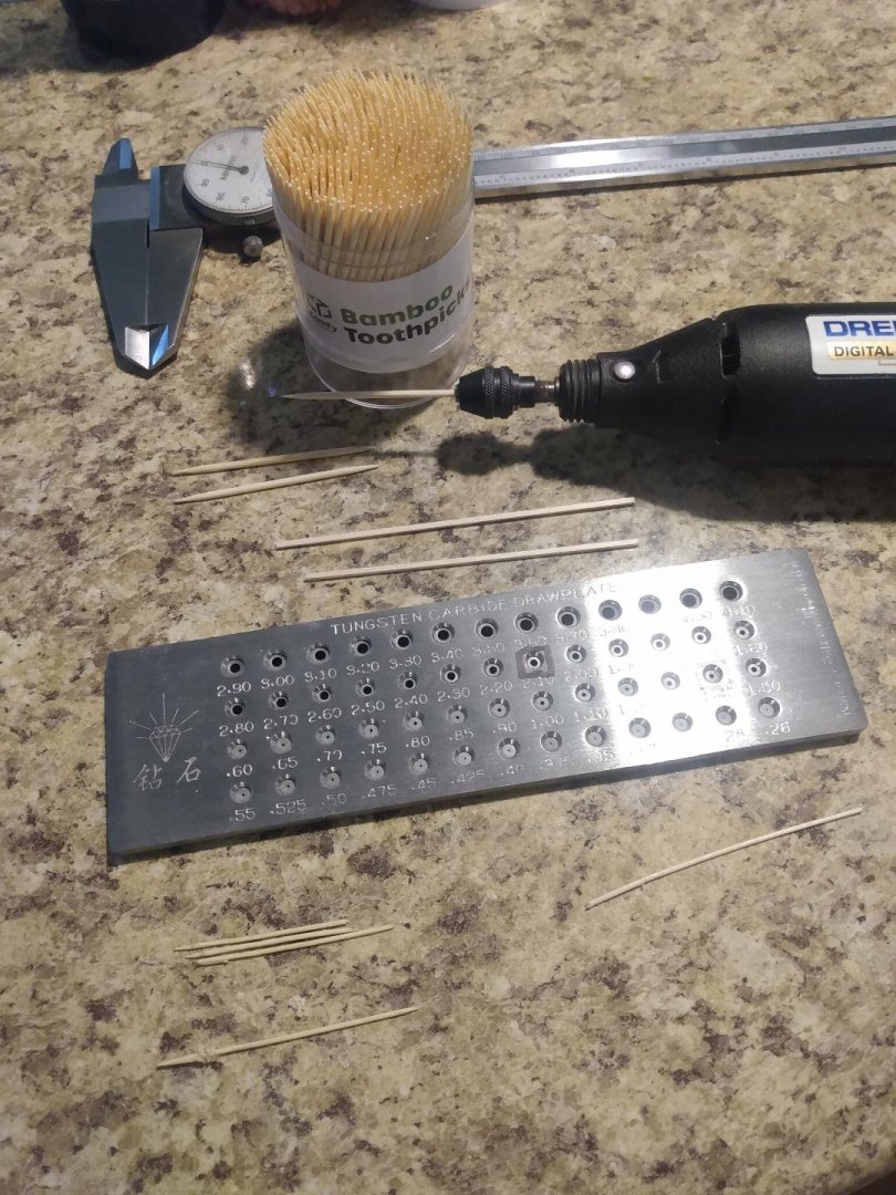
-
Gunboat Philadelphia 1776 by tmj
tmj replied to tmj's topic in - Build logs for subjects built 1751 - 1800
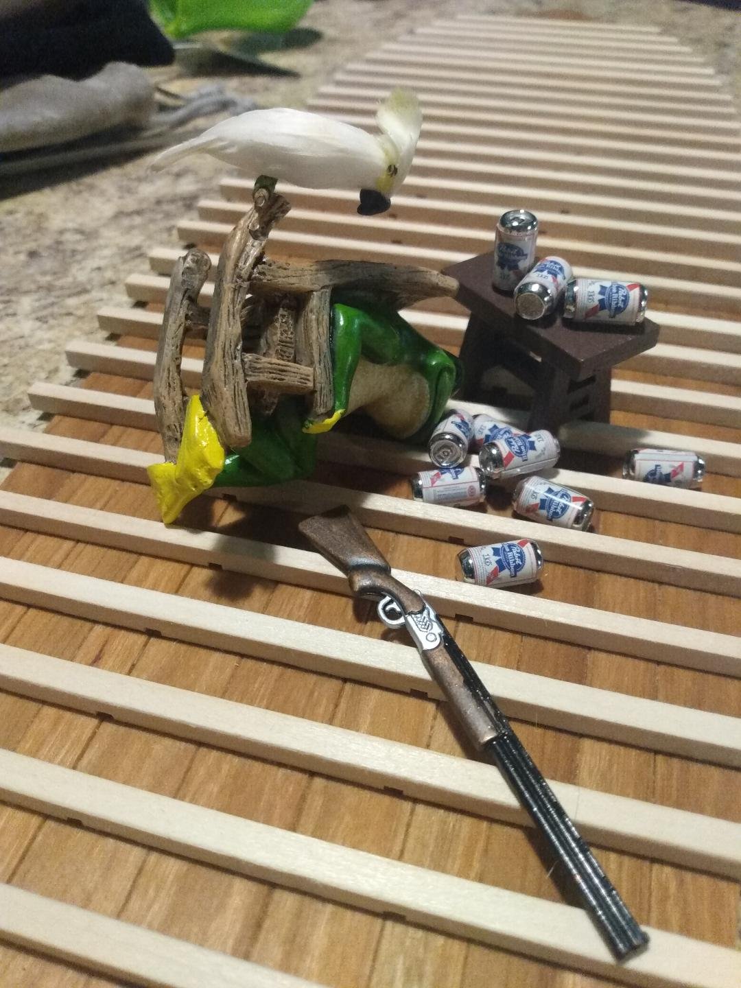
Ribbit doesn't like making trunnels. Last night he begged me to let him clean windows, scrub toilets, do "ANYTHING" but spend the day making trunnels! I couldn't oblige him. It must be done! This is how I found Ribbit early this morning when it was time to get started. I guess I'd better get a large pot of strong, black coffee going!
-
Gunboat Philadelphia 1776 by tmj
tmj replied to tmj's topic in - Build logs for subjects built 1751 - 1800
All four drilling bosses are ready. Time to start making the trunnels...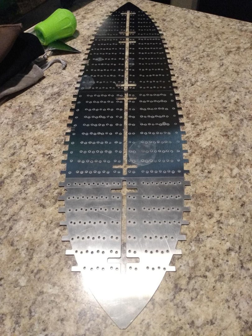
-
Gunboat Philadelphia 1776 by tmj
tmj replied to tmj's topic in - Build logs for subjects built 1751 - 1800
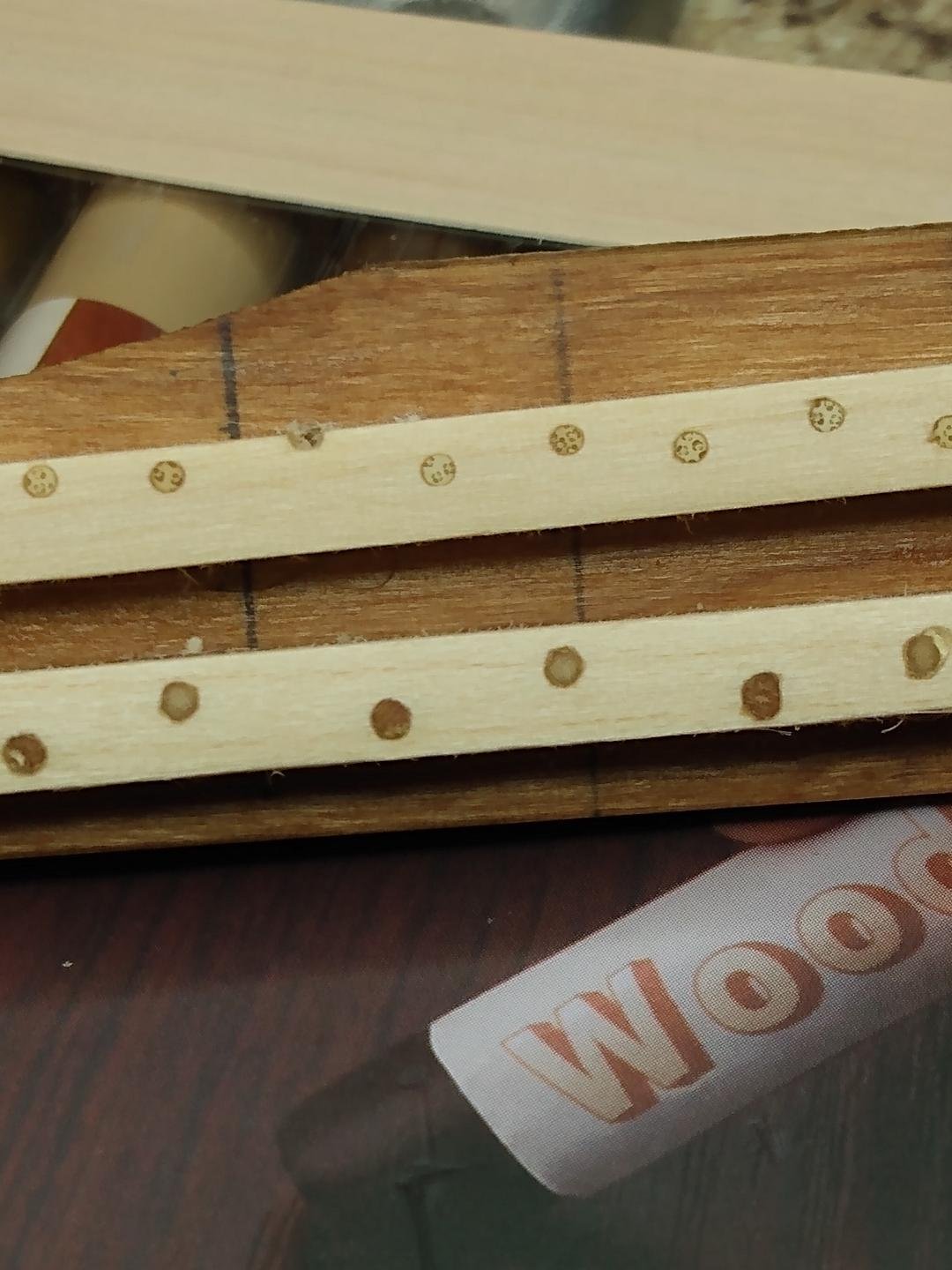
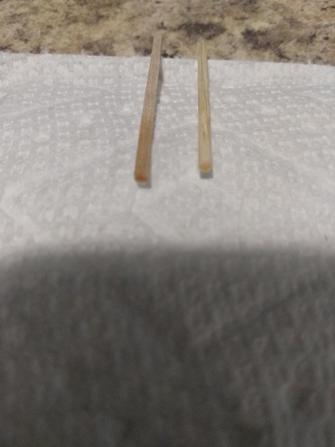
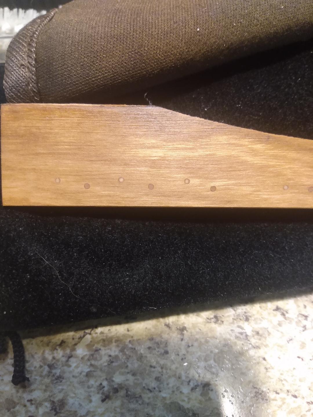
Trunnel material problem has been solved. As per the photo below... the end grain of my basswood trunnel material is shown on the left. It's quite dark after being treated with Tung Oil. What you see on the 'right' is a Bamboo toothpick that I clipped and treated with the same Tung Oil. The end grain of the Bamboo does not darken to the extent that the basswood does. I'll be drilling my trunnel holes all the way through the components to be tree nailed, however. My trunnels will only be 1/2 of that length. Trunnels inserted from the bottom planking side will be made from Basswood. Trunnels inserted from the top of the flooring timbers and frames will be Bamboo. This will provide a nice, subtle contrast in colors no matter what part of the boat is being viewed by one's eye. Nothing glaring, nothing rude... just noticeable.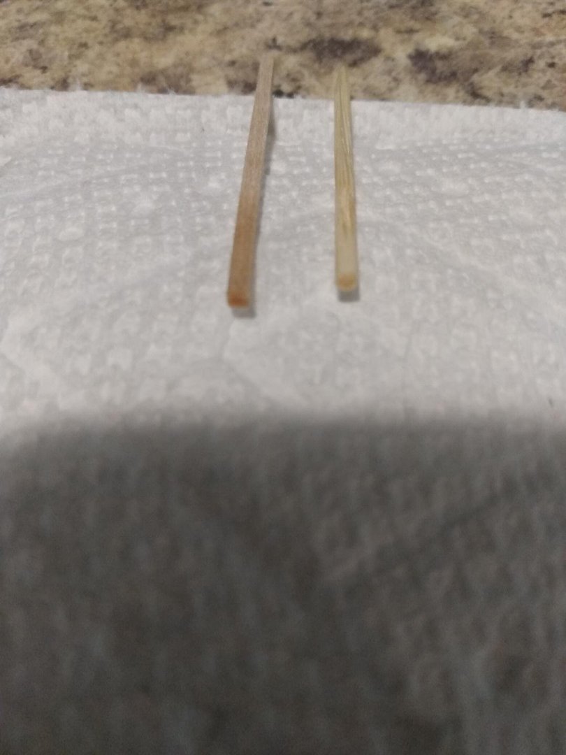
-
Gunboat Philadelphia 1776 by tmj
tmj replied to tmj's topic in - Build logs for subjects built 1751 - 1800
Please don't feel intimidated or 'left out' by what I am doing here. As per my 'aforementioned' post... there is no reason for anyone to approach this trunnel drilling thing in the same manner that I am doing it. Traditional methods of 'trunneling' any wooden ship model will work just fine on this model too! I'm simply being impatient, lazy and cheating by taking advantage of technology that I happen to have on hand. -
Gunboat Philadelphia 1776 by tmj
tmj replied to tmj's topic in - Build logs for subjects built 1751 - 1800
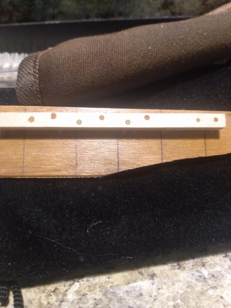
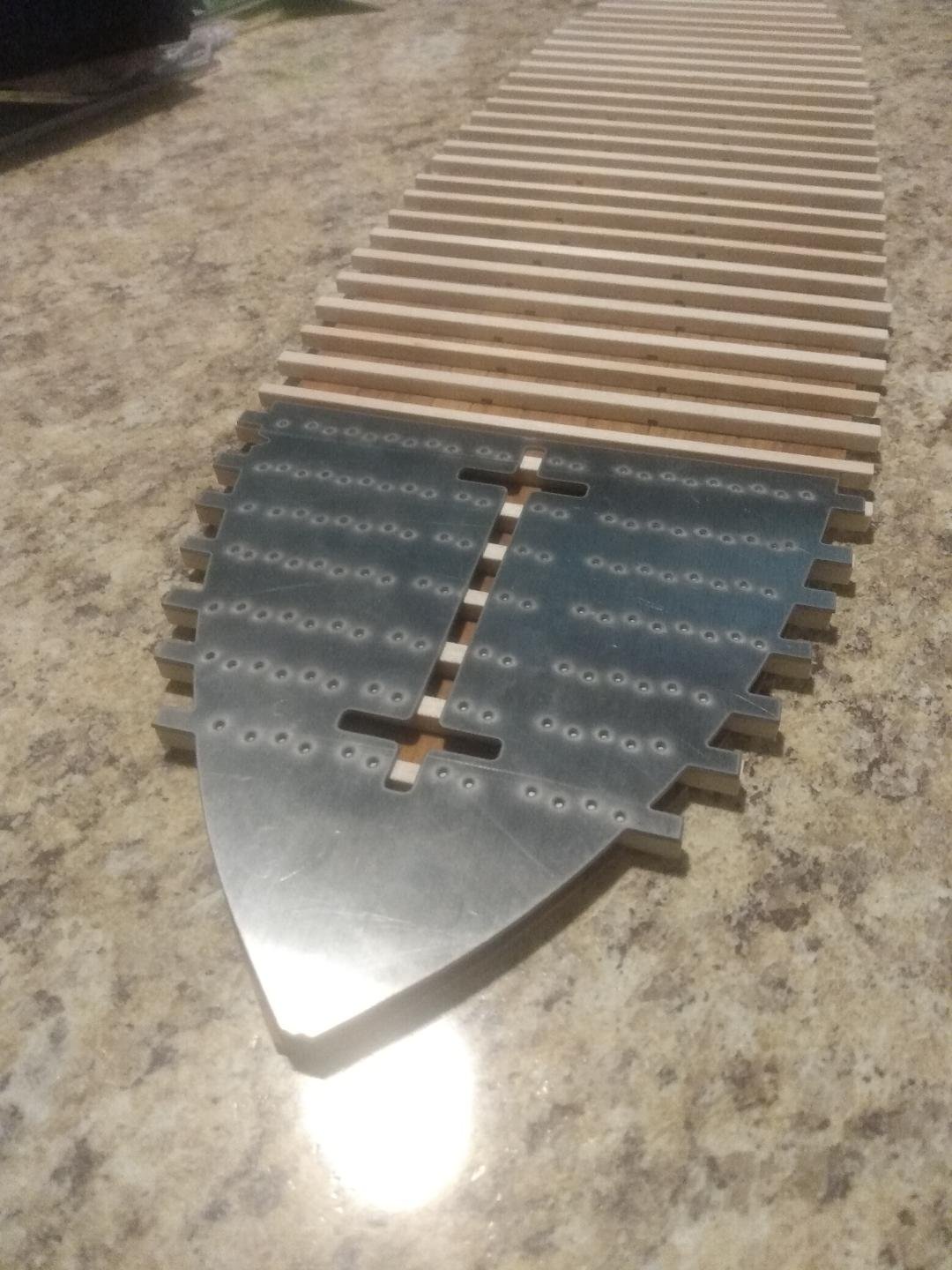
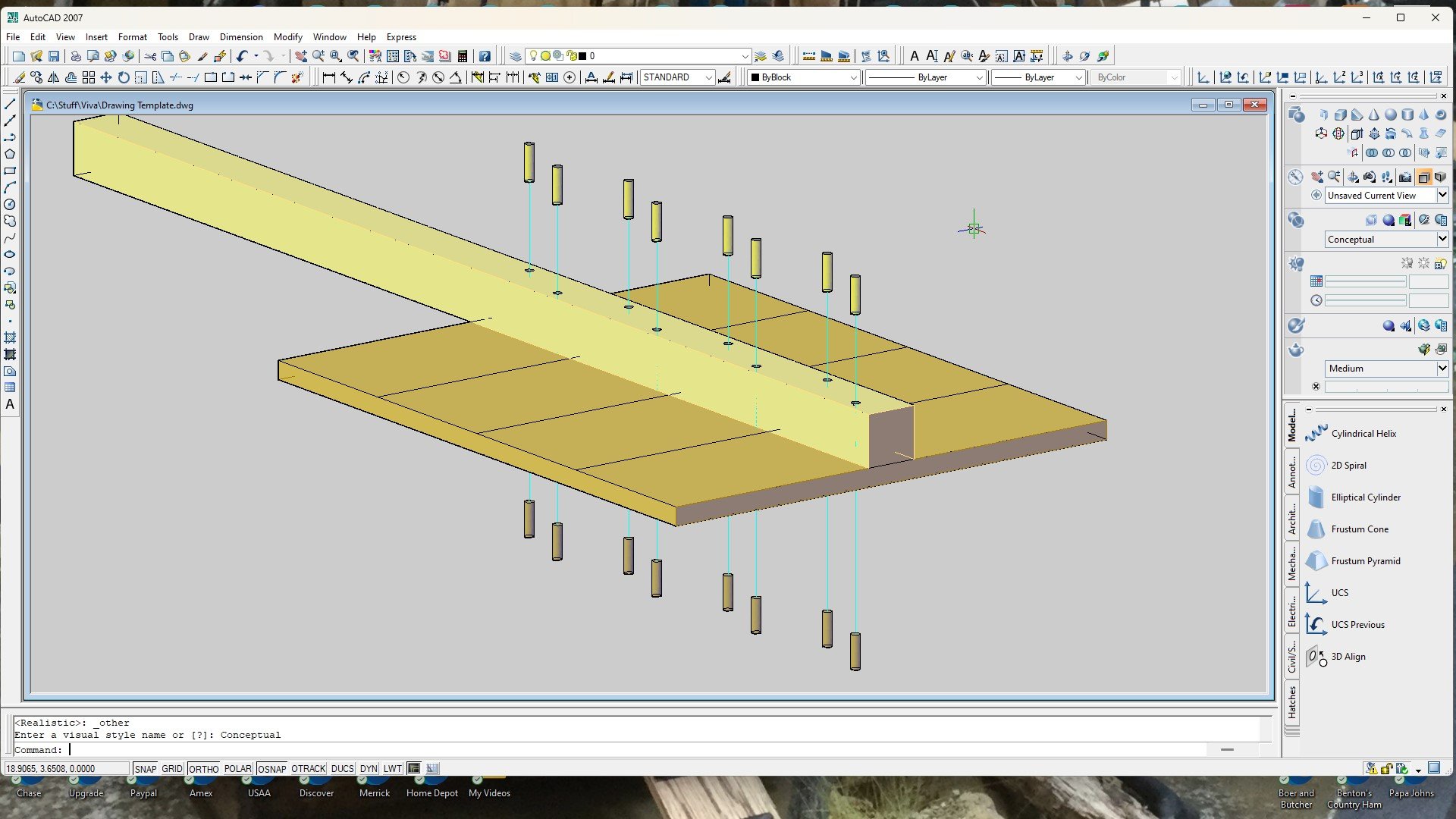
I called the laser operator yesterday evening and told him to burn only 'one' of the four templates. First part inspection required. When dealing with so many holes, flooring timbers of various widths, and human error... I needed to ensure that all of my measurements were actually correct and that all of my holes were truly in their proper places. So far so good. The forward template with 128 holes is spot on. No holes will be out of place nor blow through the sides of any of my flooring timbers, at least not on 'this' drilling template. The slots cut in the middle of the template are simply sight gauges allowing me to locate the center line and also see the edges of the flooring timbers to verify that the trunnels will not break through the sides of those timbers. 'This' template passes QC inspection, so I'm going to have the other three templates cut without inspection.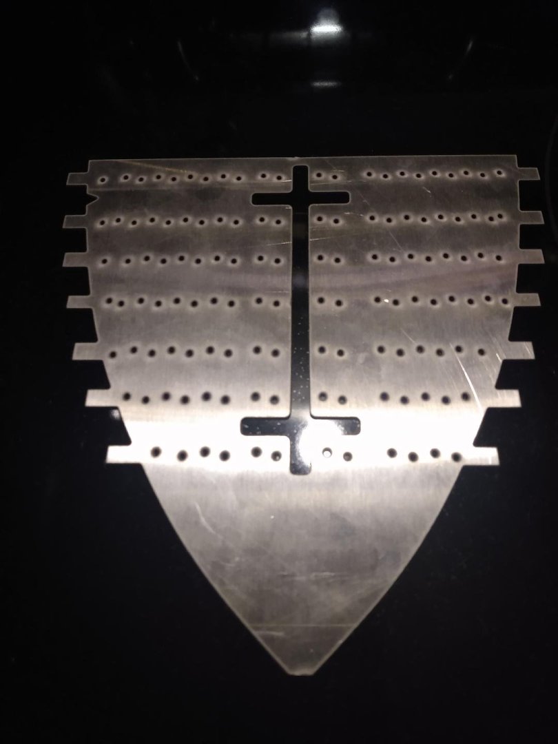

-
Gunboat Philadelphia 1776 by tmj
tmj replied to tmj's topic in - Build logs for subjects built 1751 - 1800
I'm actually using a Dremel and a Dremel drill press. The problem is that the only proper sized drill bits I could find for a 1:24 scale hole are a bit long. I can't seat them far enough into the Dremel's chuck to only have a short part sticking out. That's where the wobble and bit wandering comes from. I could probably cut the bits shorter, but with a SS drilling boss, why bother. My templates will guide the bit without allowing any drift.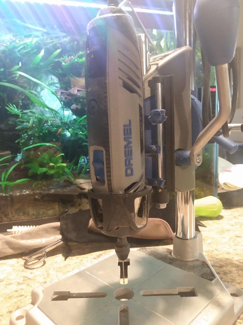
-
Gunboat Philadelphia 1776 by tmj
tmj replied to tmj's topic in - Build logs for subjects built 1751 - 1800
Still experimenting with the trunnels. I was going to simply print out a paper drilling template but noticed that my drill-bit would wander off target, just a bit, every time the point of the drill bit touched the wood. That probably wouldn't happen if I used an awl to poke a 'pilot' indentation into the wood prior to drilling, but there was also another problem that I ran in to. That problem being close tolerances to prevent me from accidentally drifting too far off target, for my holes, and accidentally blowing out of the sides of the flooring timbers via me just missing the target, or the drill bit drifting upon initial contact with the wood. With a paper template I could not see if I was properly aligned with all of the flooring timbers before drilling. I also noticed that after leaving my paper template taped to a practice dummy, overnight, the paper had expanded due to a sudden change in humidity and the template was no longer fitting proper for drilling accurate holes. "Hmm?" That's not good. It's going to take me a few days to drill all of those trunnel holes, and I can't have my template changing every day. To solve this problem, I'm getting rid of the paper template and going with a hard template that won't be affected by the weather. I've divided the bottom of this build into four sections. Each section will have its own separate template with viewing slots to ensure that everything lines up properly. These templates will be made from .035" thick stainless steel. There's no reason why such templates cannot be made from cardboard, thin plywood, etc. The only reason that I chose thin stainless steel is because I have a ton of that stuff at work and also a laser to cut it with. It saves me a lot of time, which is something that I currently just don't have enough of. I need to cheat if I'm going to keep this build from bogging down and going stagnant right after getting going! I've also purchased some Bamboo toothpicks to draw down into .042" diameter trunnels. I want to see how the 'end-grain' of those drawn bamboo trunnels take to a clear-coat finish. Fingers are crossed! The night shift is supposed to cut out my templates. Hopefully they'll be ready tomorrow.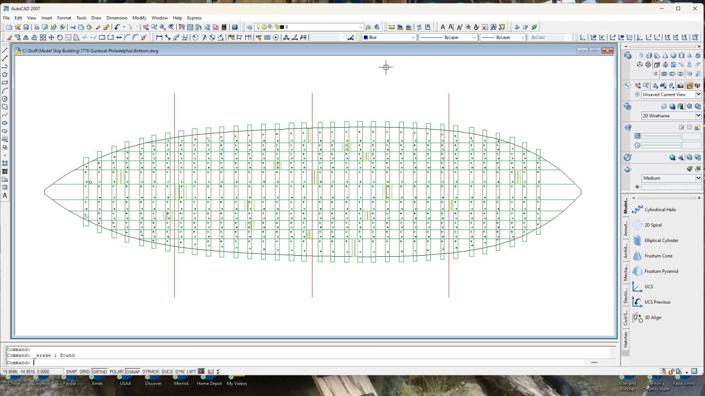
-
I see that. Very difficult to read, however. Just 'eyeballing' proportions... I'd say that it should float, as drawn, with a good bit ballast up front. I agree with you. Mr. Pellett needs to chime in here!
-
I've been scratching my head on that too. Is there any chance that what you are building is actually a 'waterline' model that truly has a much deeper draft than what is seen? That would allow for needful water displacement as well as room for necessary ballast, in the forward section, to counteract the weight of that 68-foot-tall driver. Wouldn't help much in high winds or rough water though. Could those 'towers' be laid down for transport and rough weather?
-
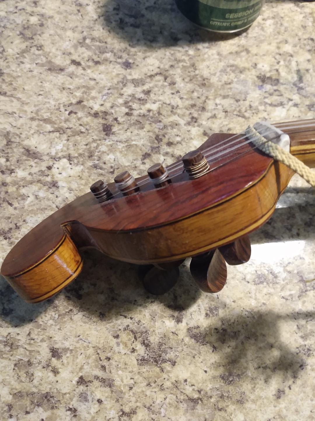
I've built a lot of guitars in the past years. I like to decorate my headstocks with exotic veneers for added effect. I use Titebond glue for that. After cutting my veneer(s) slightly oversized I smear the glue on both my veneers as well as my head stock then walk away for a few hours, or a day to let the glue dry. I then break out my 'heat sealing iron', used for applying heat shrinking plastic to my R/C airplanes, and simply iron the veneers to the headstock of the guitar neck. It bonds instantly and will never let go, unless heated up again and pried off with a spatula. This technique works extremely well. The below image is of the headstock of a gourd banjo that I built for myself about 12 years ago. I used multiple layers of different colored veneers to achieve the effect that I wanted. Looks as good today as it looked 12 years ago! 🙂

- 13 replies
-
- 11
-

-

-

-
Gunboat Philadelphia 1776 by tmj
tmj replied to tmj's topic in - Build logs for subjects built 1751 - 1800
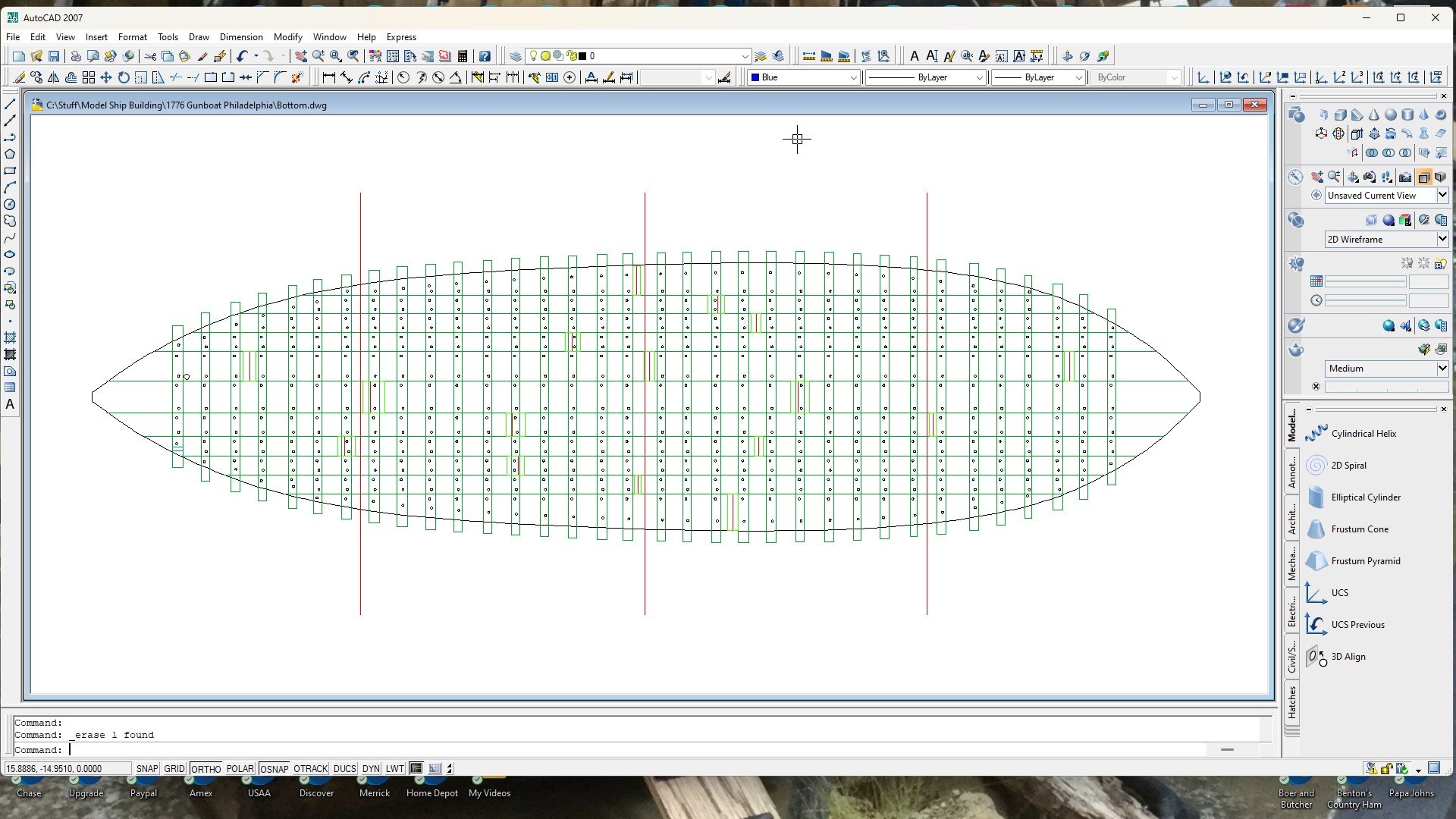
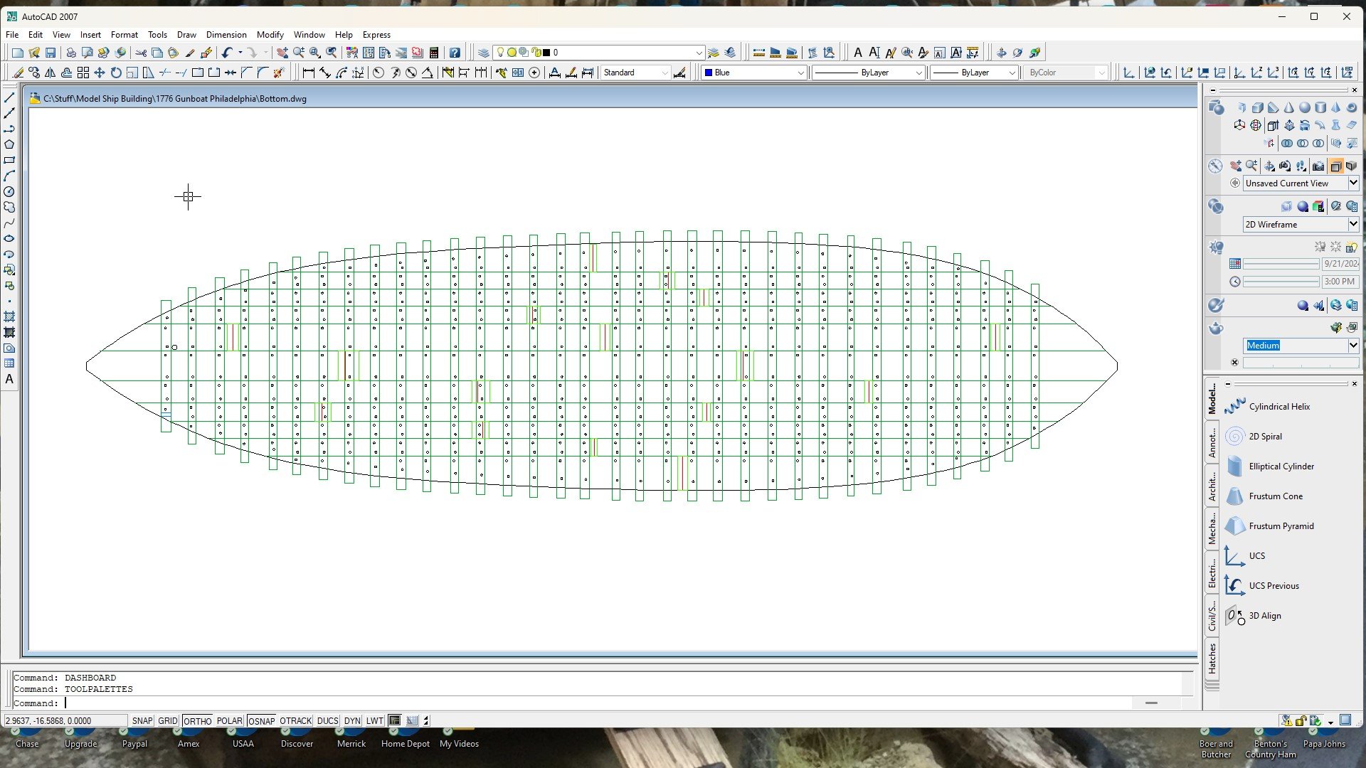
Here's my current layout for the butt-splice planking plates (nailed, not tree-nailed) and the bottom planking trunnels (tree-nailed). I'm going to need to dig a bit deeper into the Smithsonian drawings to see if there are more details on 'other pages' that are not shown on page #4 of 16 pages. The details on page #4 show trunnel details for only one flooring timber that is located close to the bow. Long story short... It just looks as though there should be more trunnels in certain areas, especially in the wider planks. I know that these gunboats were not designed to last very long, so this could very well be the actual layout, however. I need to dig a bit deeper just to ensure that this is actually correct before I continue.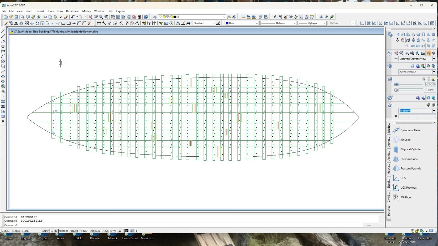
-
Gunboat Philadelphia 1776 by tmj
tmj replied to tmj's topic in - Build logs for subjects built 1751 - 1800
I enjoy cats. They are low maintenance and can be quite entertaining. I have three right now. They are all rescues. One is the pilfering Ocicat, there's also a Bengal, and last but not least a very curious cat that we aren't sure about, nor can get any info about. She's much larger than the other two rescues. We think she might have some Bobcat or Lynx in her. She drew a LOT of blood from me and the Mrs. during the first three years but has since come to trust us and has become a big, gentle lady. It just took time, patience and our being chewed on, without retaliation for a while before she finally mellowed out. She was bad, really bad at first. When she bit, she'd bite incredibly hard, send her fangs deep, and then start to shake her head violently like she was trying to rip flesh off. Nowadays, we'll get a gentle nip now and then, kinda like a love bite. It's not intentional but rather seems to be something from instinct. Sometimes her love bites draw a little bit of blood but most times not. We knew what we were getting into when we adopted her. Had we not given her a chance she would have likely been euthanized 7 years ago. She's now a really sweet girl and a big part of my family. We don't worry about visitors. She will hide when anyone comes over and not come back out until after they have left, and the coast is clear. -
Gunboat Philadelphia 1776 by tmj
tmj replied to tmj's topic in - Build logs for subjects built 1751 - 1800
I have an 'OciCat'. She's a hoot, but she also likes to pilfer things and hide them in strange places. I just caught her running out of my shop with a baggie in her mouth, heading under the bed in the bedroom. That baggie contains my drawn, experimental trunnel materials. Ribbit caught her in the act, but it was too late to stop her before she made her fast 'get-away'. I was able to recover the goods and Ribbit is now ready should she try another daring act of such thievery!
-
Don't feel bad. I think a lot of us spend a great deal of time looking at curious things that most folks would question our sanity over! ... not that 'I'm' one of those types to stare at odd things, no, not me!
-
Gunboat Philadelphia 1776 by tmj
tmj replied to tmj's topic in - Build logs for subjects built 1751 - 1800
Not to worry Keith. I'll be testing everything on scrap before I implement it into my actual build. 'Cheesy' will never be an option. If something looks improper, I'll try something different... and keep trying different things, one step at a time, until I finally come up with a proper solution. Thanks for that link to "Methods for Making Treenails". There are some good hints in that link. -
Gunboat Philadelphia 1776 by tmj
tmj replied to tmj's topic in - Build logs for subjects built 1751 - 1800
Keith, What about those pastels you are using for 'grunge' on your pile driver? Would that stuff stick to the end of a flat tipped punch and be able to be pressed onto the basswood timbers? Would it stick to the wood well enough for me to fix it in place with a spray of clear coat? -
Gunboat Philadelphia 1776 by tmj
tmj replied to tmj's topic in - Build logs for subjects built 1751 - 1800
Thanks Gary! I'm not sure if sealing the ends will also darken the end grain. More experiments are needed. I'm going to make a cheater-template for drilling all of the trunnel holes (got a flat bottom, might as well take advantage of that flatness) and will be thinking more about this while working on that template. -
Gunboat Philadelphia 1776 by tmj
tmj replied to tmj's topic in - Build logs for subjects built 1751 - 1800
Hi Keith! If it weren't for the really light-colored Basswood flooring timbers, inside the boat, I could live with that. The cherry trunnels are indeed noticeable on the Cherry bottom planking, but also not too awfully prominent. They are obvious and quite easy to see but not glaring and rude. My problem isn't so much with the Cherry bottom, but rather with the end grain of the trunnels that will be seen atop the light-colored Basswood flooring timbers... as well as the Basswood frames that will eventually be tree-nailed atop that Cherry bottom planking. the end-grain of both Basswood and Cherry are proving to be a bit too noticeable and "in your face" atop that really light-colored Basswood. I don't want that! I'm thinking about maybe 'faking' trunnels on the Basswood by grinding a steel roll-punch tip down to the required .042" diameter of a scale trunnel, then lightly 'punching' the surface of the Basswood to leave a shallow indention that I can fill with PVA glue and sand flush. That will be my next experiment. If 'that' works, my fingers will thank me. Drawing trunnels through a drawplate isn't exactly what I call having fun! 🤨 -
Gunboat Philadelphia 1776 by tmj
tmj replied to tmj's topic in - Build logs for subjects built 1751 - 1800
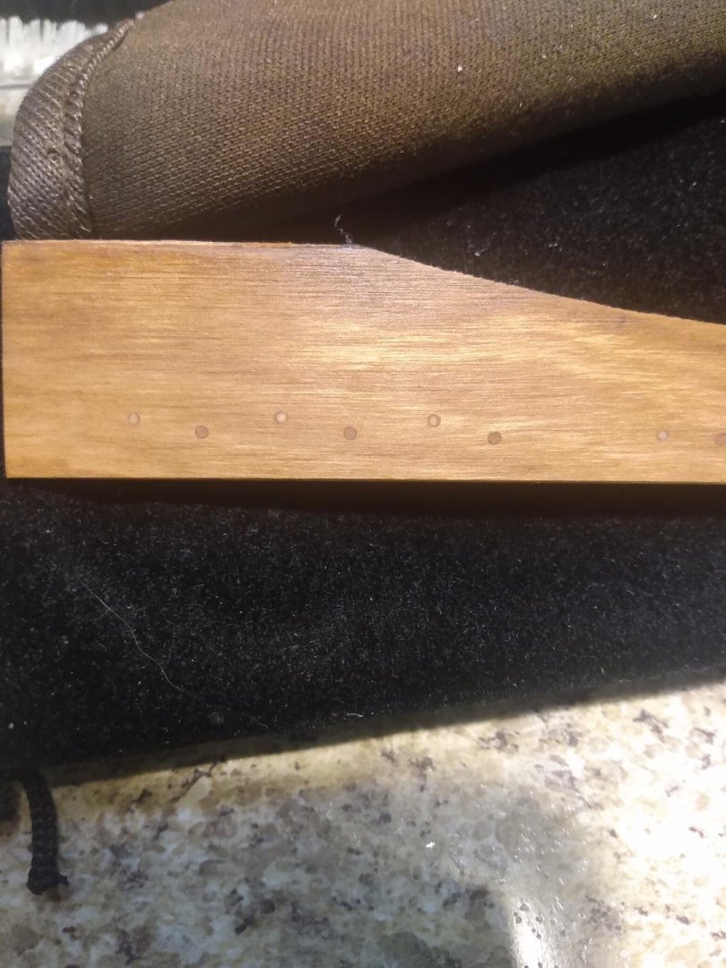
The octagonal shaped trunnels are a "No-Go." It's too difficult to pass the small pieces of wood through the draw plate, numerous times, with perfect orientation each time through the hole(s). I was unintentionally rounding off the sharp corners of the intended octagonal shape and thus making the trunnel material somewhat round as a result. "Oh well, I tried!" Trunnels will be round. I'm now debating on the 'color' for the trunnel materials. The bottom of the boat is Cherry, and the flooring timbers are Basswood. With the interior of this model being exposed, I want contrasting colors between the different components of the structure. My idea is to use 'split-trunnels'. Darker wood for the Cherry bottom planking exterior and a lighter color for the Basswood flooring timbers inside the model. I want the trunnels noticeable, but not too loud nor strikingly obvious. My 'split-trunnel' plans... The Basswood trunnel material is my favorite for the bottom planking. It's not too loud and the 'halo' around the perimeter of the trunnels, produced by the Tung Oil, adds a certain depth of complexity and visual interest that I like. The Cherry trunnels just look like dark dots. No real character. Let me know what 'you' folks think. Do you prefer the look of Basswood trunnels, or Cherry trunnels? As for the interior, atop the flooring timbers... I don't like the Basswood, nor the Cherry. The Basswood end-grain gets too dark when the Tung-Oil is applied. The Cherry is just too dark to begin with. This is way too loud and 'striking'. I need some wood, or suitable material that will 'closely' match the color of the Basswood after a couple coats of Tung-Oil finish are applied. Does the end grain of Bamboo absorb color and darken, when finished, like the Basswood? I'm open for suggestions here. If you know of a good material, please chime in. Please pardon the ugly holes. I was playing with different drill bit sizes and RPM's looking for the proper setup. "Found it!" It's 'Sci-Fi' Saturday. I think I'll take a break from the Philadelphia and do a bit more design work on my wooden 'Steampunk' "Seaview Submarine" design while watching 'Svengoolie' and "Voyage to the Bottom of the Sea" on MeTv tonight.
.thumb.jpg.93bf6f192cb541f3d86679c23234bf01.jpg)
-
Gunboat Philadelphia 1776 by tmj
tmj replied to tmj's topic in - Build logs for subjects built 1751 - 1800
All 34 flooring timbers are 'finally' in place. I'm now scratching my head trying to figure out how to approach those 'octagonal' shaped trunnels. "Hmm?"...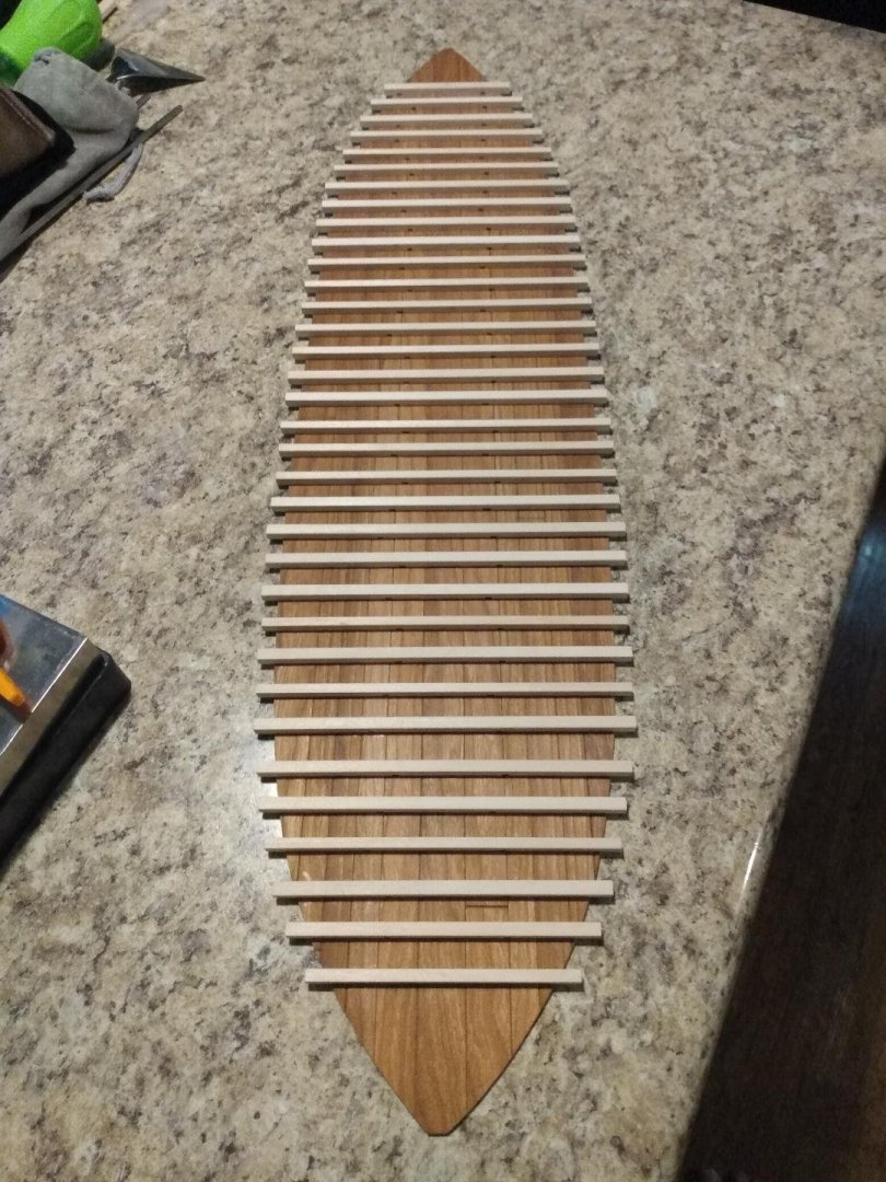


.jpg.ee940c9505e14081ed570b4abb68ddb3.jpg)
