

KrisWood
-
Posts
306 -
Joined
-
Last visited
Content Type
Profiles
Forums
Gallery
Events
Posts posted by KrisWood
-
-
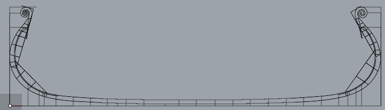
Got the keel faired. The numbers in the paper are more accurate than those in the Saga Oseberg book.

-
I'd disagree on one point only. The paper and its contents are intellectual property of the Viking Ship Museum in Roskilde, Denmark.
I think as long as we don't redistribute the original PDFs we'll be ok.
Edit: I've got the keel and stem cross sections done. Next step is fairing them together and drawing the 3D curves.
Edit: The paper's measurements for the keel do not fair, at least at my skill level, so I'm trying again with the numbers from the Saga Oseberg book. I'll update this in a bit when I get a chance.
-
-
-
I worked page 28 into it but it doesn't quite line up with the rest yet.
- BLACK VIKING and mtaylor
-
 2
2
-
-
-
-
First step is trying to read the numbers from https://www.academia.edu/49550641/Rekonstruktion_af_Osebergskibet_Bind_II plan 2 (page 26). This will be necessary for the curvature of the keel, which is what all other numbers are based on.
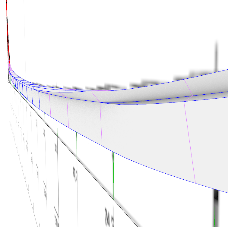
I've got all the numbers plugged in from page 29.
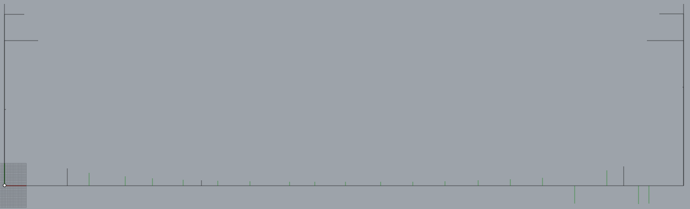
The green lines are the stations. Lines below the base line are ones for which no height was given in the plans.
- malachy and Scottish Guy
-
2
-
Hi all! It's been a while. I had to take some time away while life got in the way of hobbies. Things are settling down now and I'm thinking about picking this up again.
This time around I'd like to start over and do it open source. Most of the lines can be derived mathematically. Some of the lines cannot be derived mathematically and must be based on existing reconstructions.
My question is, if my CAD files are drawn by hand by me, how different must they be from existing plans to count as original work?
- malachy, mtaylor and Scottish Guy
-
3
-
4 minutes ago, Waldemar said:
In the simple, soldierly words: forget it, it is all waste of time...
That is what I thought.
I found the equivalent of Max's FFD boxes. It's called Cage and CageEdit. It takes a little getting used to but gets it into the right ballpark and I can improvise from there, though it's never going to be exactly accurate.
-
Two questions for you all...
1. How do you project curves onto a surface in Rhino?
2. My reference materials from the stems are, I think, based on Johannessen's reconstruction drawings and Sofie Krafft's detailed drawings of the carvings. They do not line up with Ms Bischoff's reconstruction. In my game modeling days in 3D Studio Max there was a tool called Free Form Deformation that could scoot curves into place en-mass in situations like this. Is there an equivalent in Rhino?
-
-
And next question is, depth of rabbets, drawn in CAD or just the placement of the rabbets and cut them to depth physically when building?
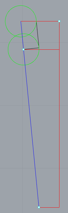
Edit: Here's a fun diagram to explain how to draw the depth of the rabbets on any Viking ship that has them. It's actually surprisingly easy.
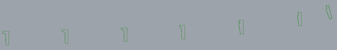
The following is a cross section of the stem at a point where I have no numbers beyond those calculated from the documentation for top and bottom width of the keel / stems.
The plans have lines for the top and bottom of the rabbet and the bottom of the keel in profile view. I've drawn these as horizontal lines in RED.
Given the measurements of the widths from the documentation, I can now make a trapezoid shape connecting the dots, which I've done in BLUE.
Next I draw the depth of the keel as two circles, centered at the intersection of the red lines with the blue line, which I've drawn in GREEN. I'm not bothering to taper my planks, so my circles have a diameter of 2.5cm along the entire length of the keel / stems.
To get the correct ANGLE of the rabbets, draw a line connecting the two circles from the intersection of the top circle with the top red line to the tangent of the bottom circle, which will give a perfect right angle to the bottom of the rabbet, drawn in BLACK.
-
Question: Is there a good (free?) automated tool for importing ship plan drawings from any raster format into any vector format which can be imported into Rhino?
I've tried a number of methods but they all end up with curves drawn as bubbles around the black lines rather than through the middle of the black lines.
I've got photoshop if anyone knows of a method there as well.
-
-
-
-
-
Hi everyone! It's decision time.
I am unable to proceed with a wood project at the moment. In the meanwhile I'm going to proceed with card unless anyone has a CNC mill and wants to collaborate on making parts. (Anyone here interested?)
Now I'm considering two questions:
-
What is a good scale for working with card? 1:75 fits the entire keel on a single US Letter sized sheet of card stock so I can print it in one piece, but I think the parts will be too tiny to get the level of detail I'd wanted for my project.I've decided to go with 1:50 - Since this thread is for my wood project, should I start a separate one for my card project, or just keep posting here? I've also got a separate thread for my CAD related questions in the CAD forum.
-
-
Ha. Hahaha. HAHAHAHAHAHAHAHAHAHAHA.... 🤪
I went and added my beautiful, new, mathematically derived lines for the stem back into my guesstimate that I'd made before the new, more detailed plans and numbers were published. All that work and none of the lines moved by more than a centimeter... My old guesstimate was as close as makes no difference at scale... 😆
That said, I guess I'm going back to a previous save and simply converting my files to a card-friendly scale/format...
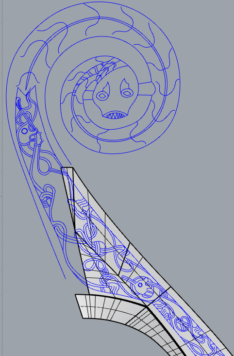
Edit: Also, the way I ended up getting a three dimensional stem-top was to take Johannessen's cross sections and adapt them to Bischoff's numbers, then voila, it matched Saga Oseberg. In doing so, I realized a simple truth about all Oseberg reconstructions. Every last one of them is historically inaccurate.
In Mr Finderup's "Saga Oseberg" book, he explains that they ran out of time at the end of the project to fully analyze the remaining fragments of the stem top, so they went with a mathematically derived approximation in a single solid piece, even though the original used multiple pieces.
Comparing excavation drawings to both Johannessen's and Bischoff's reconstructions, the original stem top would have been somewhat larger and at a different (somewhat unknowable) angle. Because it makes zero difference to the functioning of the ship, I think Ms Bischoff's approach is the correct one. Johannessen did what looked good for the museum display. Bischoff did what functions given the most probable dimensions of the planks which made up the hull of the ship.
-
-
8 hours ago, Waldemar said:
The size of the inserted bitmaps into the posts is reduced (probably to a maximum of 1440 pixels of the longer side).
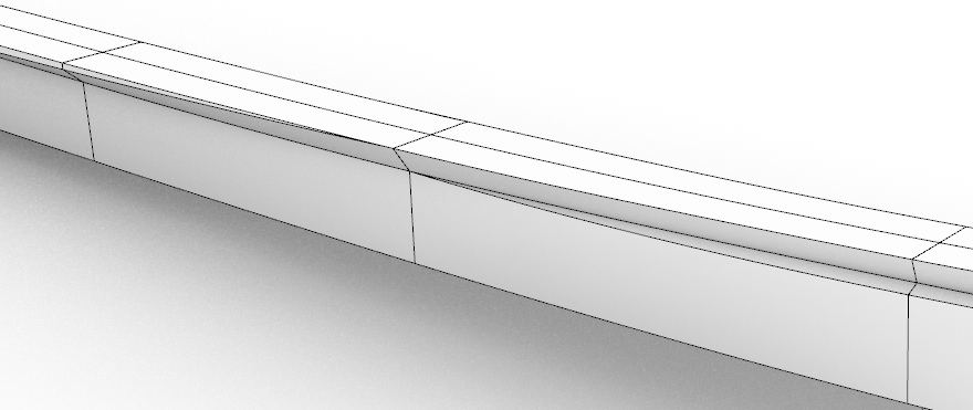
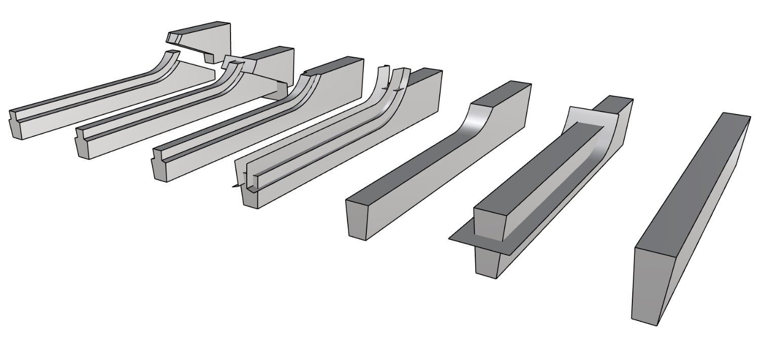
Yes, these are quite nasty shapes to model, but possible. Try it this way, but your initial polysurface needs to be closed (for better clarity and less working time a straight element in this sample):
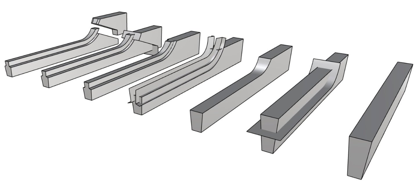
This is not the only way, but probably the most convenient.
Count me amazed. How do you do that so fast? Are you using Rhino?
The rabbets can be modeled more simply as being perpendicular to the inside of the stem and not cut out. That's how they were made on Saga Oseberg. They didn't cut them until they were ready to lay the next plank down, and then they cut it to the depth of that plank.
-
Hmm when saving it as a jpg it blurred the numbers horribly


Redoing Oseberg
in CAD and 3D Modelling/Drafting Plans with Software
Posted · Edited by KrisWood
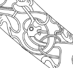
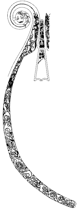
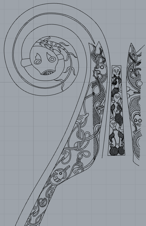
I've redrawn the fore stem. The cross sections in the original drawings are not to scale so they can't be used directly. I've redrawn the widths of the sections to scale using the numbers from the paper, but cannot reconcile them with the curves of the stems. Can anyone help? I've put my newly drawn stem at 1:10 here as an SVG.
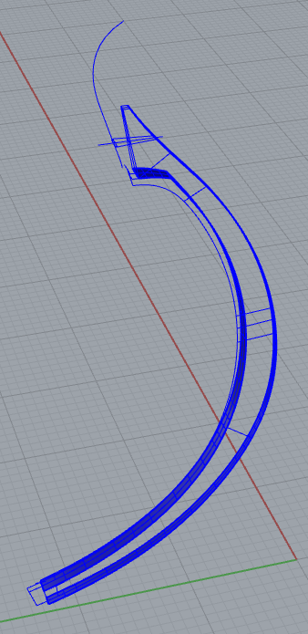
How do you draw this in 3D?
stem.svg