

KrisWood
-
Posts
312 -
Joined
-
Last visited
Content Type
Profiles
Forums
Gallery
Events
Posts posted by KrisWood
-
-
I should have specified, I meant tiny functional rivets. I learned how to make brass and copper rivets by hand in my metalsmithing class in college decades ago. I think I can probably fashion an anvil of sorts out of materials I have on hand, too. I looked it up and my gas stove gets well over the melting point for both copper and brass. I just need to get the wire to make them. Now if only the craft stores in my area weren't all shut down...
It also occurred to me last night that I have no idea where I'm going to find a 0.3mm drill bit. Any recommendations for drilling tiny holes? I also have nothing capable of measuring smaller than 1mm, so I'm going to have to trust that the drill bit and the wire are the right size.
@bigpetr, the rivets for the planks on the Oseberg Ship have shafts 6mm to 7mm in width, that's ~0.3mm, or 28 gauge at 1:25 scale. I forget the size of the heads, I think it's about 22mm to 25mm for the diamond shaped plates that go between the rivet heads and the plank. I'll look it up again after work.
-
-
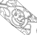
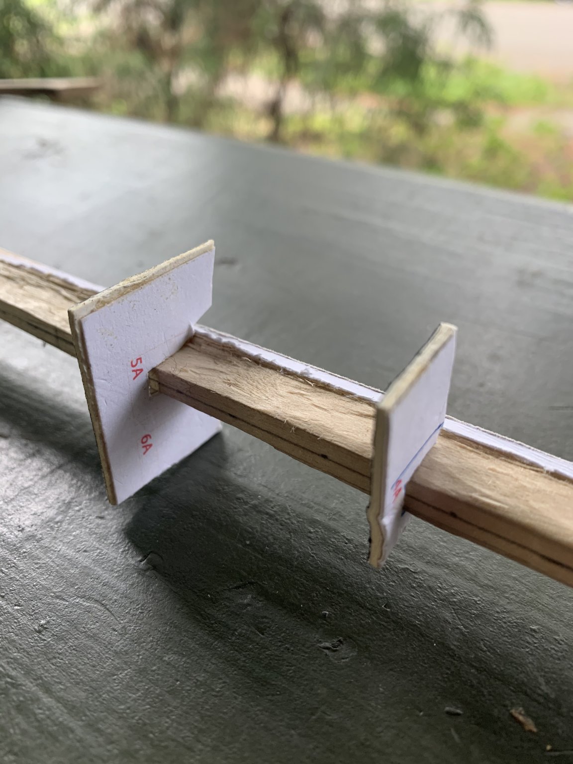
Ok I take it back. I couldn’t resist posting a photo. Here's the best section of the keel shaped to the cross section templates. I stopped trying so hard to make the keel fit in the templates when I realized it was moot without having the bulkheads to align the curves.

- Cathead, Larry Cowden, Louie da fly and 2 others
-
 5
5
-
Minor update: I roughed out the "T" of the keel last night. Nothing photo-worthy, it looks awful rough-hewn as it is at the moment. Next step will be building the jig. There's no point doing any further work on the keel until it's aligned with the bulkheads and I can see the curve of how the garboard strake aligns with the keel. I'll get started on that tomorrow.
")
-
-
-
That’s awesome! So it basically means cross section?
-
@bolin, thank you for the translation, you are my hero today! There are more detailed drawings by the conservator, Johannessen. I'll check them for the word "snit" also. I should have guessed that myself, as I speak a little german, which has a very similar word "schnitt" for "cut", but I didn't know that that would mean "drawn flat" in this context.
This will be very helpful information once I start making the frames!

-
Actually, while looking at the unimos website just now I did find one drawing of the some of the frames by Glende, that appear to be from the excavation, but I'm uncertain if these are drawn "flat" or if they are drawn as viewed at an angle from the front. I think I can use them, though, to determine the structure of the frames if not the actual dimensions, and then get the dimensions from my planking bulheads but with the planks trimmed off.
http://www.unimus.no/felles/bilder/web_hent_bilde.php?id=12384236&type=jpeg
- Larry Cowden and mtaylor
-
2
-
@bolin, that's an awesome build you've got started there! I find it curious that your frames seem to put the garboard strake inside of the second strake. Is this intentional? I had no idea that dories were built this way! Do you have a build log on Model Ship World that I could follow?
The heads seen along the edges of the planks in that photo of a boat after years of use are actually nails, not rivets, and may very well not be visible at scale. There are what look to be larger rivet heads along the frames further down, and those would be visible on my Oseberg model at 1:25 scale. I'll have to do some math to figure out the exact measurements for my nails, trenails, and rivets once I get to the point where I'm planking this thing. At the very least I want to include the rivets and trenails that hold the scarfs of the keel and stem sections together, but I can't do those until the final shaping of the keel and stems is done.
Yes, the frames of the real life Oseberg are angled. I'm not sure yet how I'll handle this in my model. I have very little reference for the shape of the frames. All of the drawings I have are from the front view as drawn by Johannessen (the conservator of the ship that put it together in the museum), and Lundin (who drew plans based on the museum display of the ship. The only plans I know of that show the frames in their actual dimensions as if laid flat on the ground were drawn by Glende, an engineer who drew all the parts of the ship in situ as they were excavated. Unfortunately, though multiple sources reference Glende's sketchbook, I have been unable to find a copy of this anywhere. I only have a handful of drawings from it that are publicly available through the photo portal on the http://unimus.no/ website.
http://www.unimus.no/felles/bilder/web_hent_bilde.php?id=12417098&type=jpeg
It doesn't help that all the websites that have information about it are in Scandinavian languages that I do not speak. >.<
- Larry Cowden and mtaylor
-
2
-
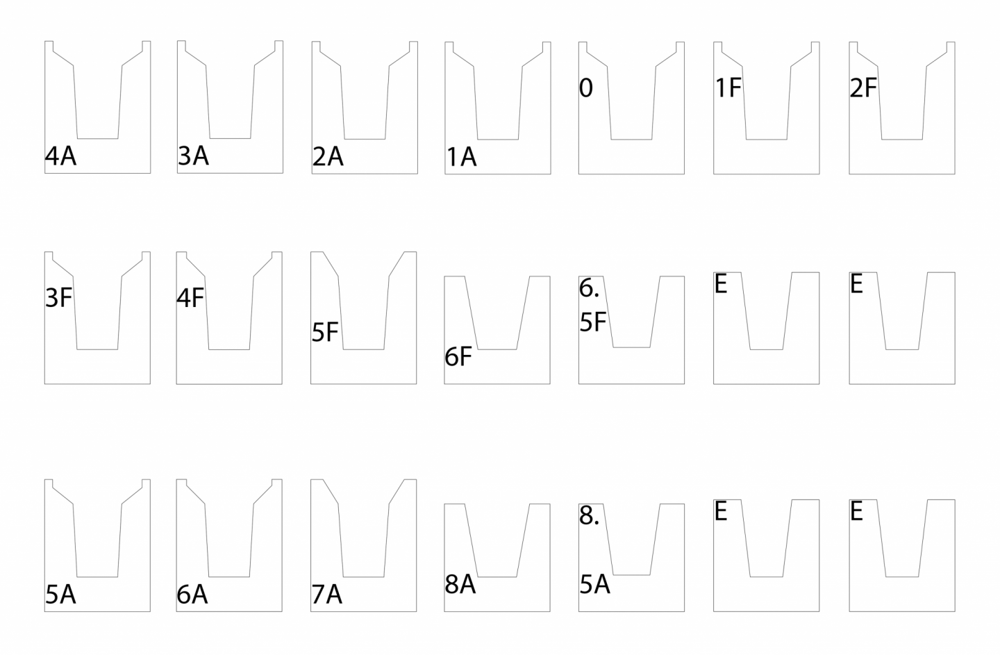
Next step will be the "wings" of the keel. Since I drew these templates myself based entirely on the calculated coordinates of each point at scale, and they look nothing like the plans from the book when drawn this way, I figure they're not copyrighted, so I'll share them here.
I've glued the whole sheet of templates to heavy mat board and will shave the keel a little at a time until each station fits. The templates labelled E are for the portions of the keel and stems fore and aft of the stations.
Templates 4A through 2F are identical so that's why the sheet is arranged the way it is.
- Larry Cowden and Cathead
-
2
-
I started cutting the rabbets last night and drew half of my keel cross section templates at scale for printing. It's good to be finally working with the wood again.

-
@Cathead, If you want to give it a try and share any tips you come up with, I'd greatly appreciate that! I'm very new to this so any images I can get are worth a thousand words!
Here is the best publicly available reference for how the keel is formed.
http://www.unimus.no/felles/bilder/web_hent_bilde.php?id=12384245&type=jpeg
There are better plans in the Saga Oseberg book, but they're copyrighted so I don't think I can share them here.
Edit: The two things I'm unsure of, and will have to go through some trial and error on:
- Shaping the wood in a way that doesn't absolutely mangle it to bits (I know the answer to this is to shave smaller bits off at a time with the chisel)
- How to use the cross sections from the plan of the keel to determine the final shape of the wood. I'm thinking I'll cut out templates for each keel cross section (there is one for each station line in the plans in the book), but that won't get me a smooth curve between the stations.
-
Your suggestion was perfect! I tried it on some scrap wood (a previously failed attempt at making keel parts) and it turned out to be a process very similar to cutting the rabbet in the non-wing part of the keel, just a bit more labor intensive as there is more wood to remove. I think I've got it from here.
Thank you!
-
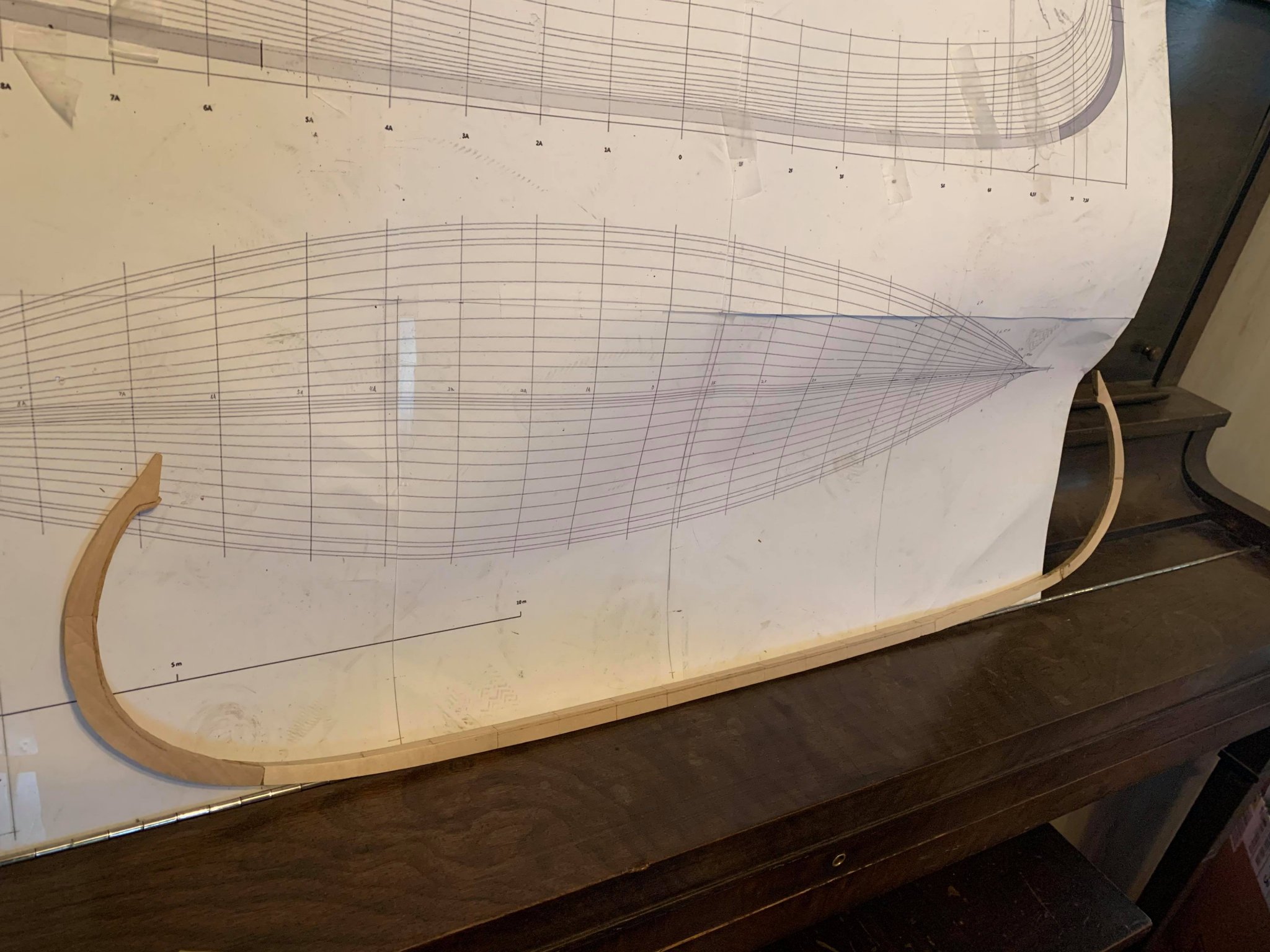
Yes I'm planning on building it "hull first" rather than "frame first". The best I can think to do would be to glue strips of wood onto a base board, with spaces between to fit the bulkheads into. The bulkheads are drawn from the cross sections in my plans, which the author confirmed for me are drawn to the inside of the planks, so they're perfect for this task assuming I can figure out how to cut them out of plywood without crossing the lines.
")
I think based on that photo and your suggestions I can figure out something for the jig.
I also have an idea plan now for how to make rivets by hand.
That just leaves figuring out how to carve the T shaped "wings" of the keel with hand tools.
-
Hi @Cathead,
I don't have a table saw, so that's out of the question. I'll be working entirely with hand tools here. I do have a Dremel that could probably do the same task, but no way to mount it without making a mount from scratch, and no way to buy such a thing during quarantine.
I'd rather not glue the bulkheads to the keel as I'd just have to remove them again, and then I'd probably damage the wood / leave glue behind in the process.
I do have some heavy gauge copper wire from my metal-smithing classes back in college. I wonder if a cigarette lighter gets hot enough to anneal it and make my own rivets hmmm...
- Larry Cowden and mtaylor
-
2
-
-
So I've got my keel assembled and I've cut out half of the paper templates for my planking bulkheads and I'm looking toward next steps. I've bolded the actual questions in case anyone doesn't want to read this whole wall of text.
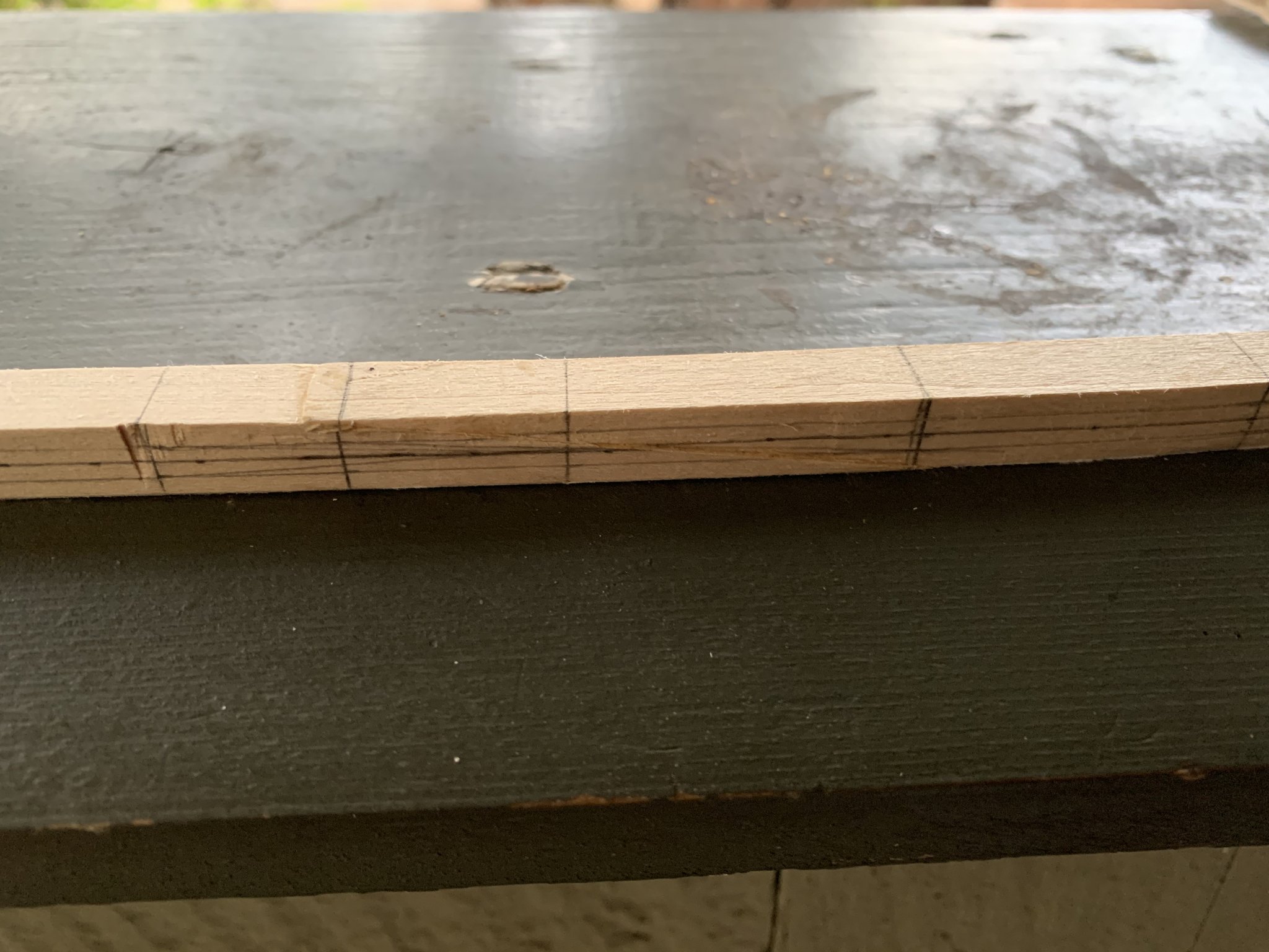
First, because it was easier to glue the keel and stem parts together when all the pieces were the same width, I made all the parts out of 3/8" solid basswood. Now I need to trim this down to the correct width for each section, as it narrows toward the stems and is widest amidships. I think I can handle this part mostly with a mini-plane and files. What I don't know how to do is the T shaped "wings" on the sides of the keel. Here is what it looks like on a real life boat:
That link explains that the T wings are shaped with broadaxe and chisel. How would this be done in miniature? Has anyone here made this kind of keel before? Can you give me any tips as to how I'd go about it?
Second, I need to come up with a planking jig to hold my bulkheads. Can anyone give me any tips for aligning them correctly and getting them to stand at the correct height? Here's an example jig I found for another Oseberg model build, but I have no idea how to construct such a thing:
https://www.arbeitskreis-historischer-schiffbau.de/mitglieder/modelle/oseberg/
I think nailing something that small into perfect right angles at exactly right spot might be beyond me. >.<
-
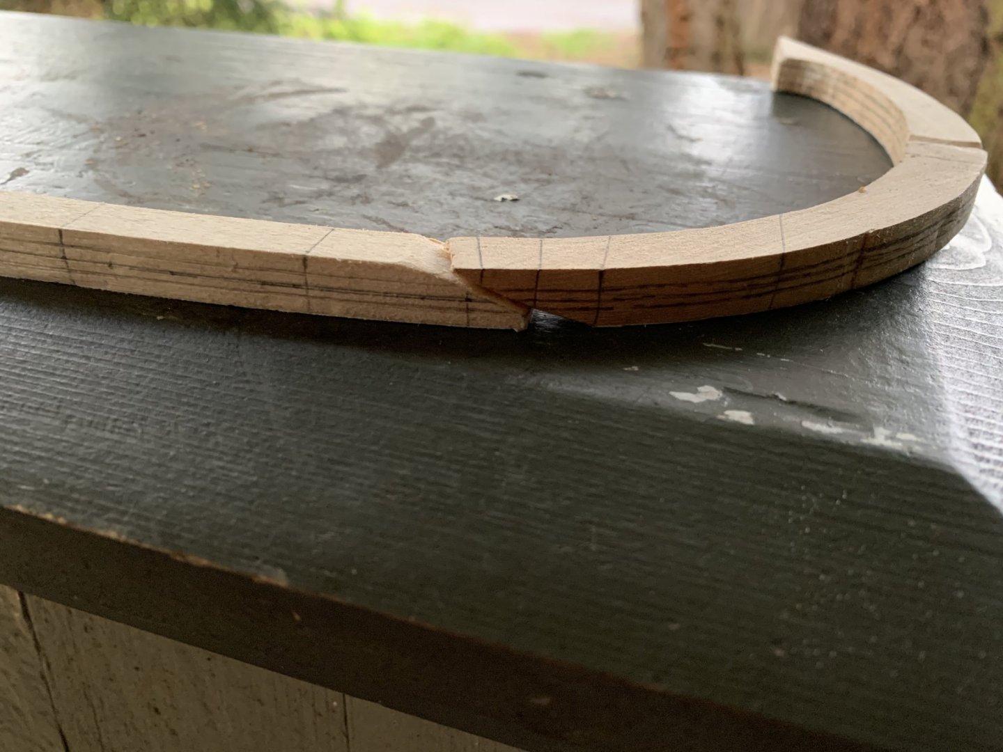
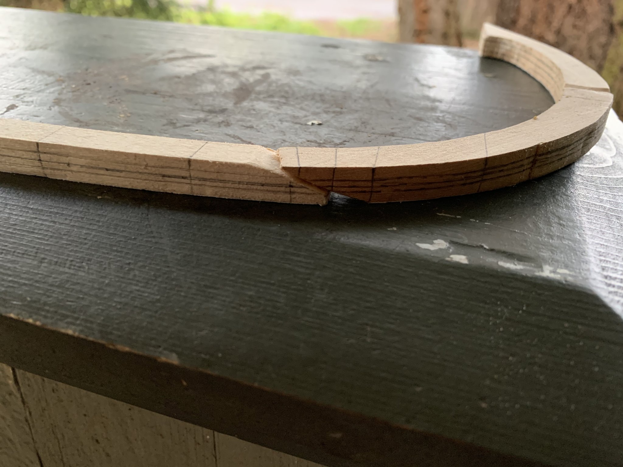
Right after my last comment, I noticed I'd messed up on another joint, too. I decided to take it apart and try it your way.
I may not have carbon paper handy, but I've got soft lead pencils. I rubbed the flat edge of the lead on the face of one side of the joint, then pressed the two sides of the joint together, quickly staining the highest portions of each face dark.
Then it was a simple matter of shaving of the dark spots until each face was perfectly flat and aligned with the other side. It worked! I'm waiting for the glue to dry now. I'm hopeful that this method will come out better than my last attempts.
Thanks again!
-
Thank you, Mark, that is great advice! I'll have to get my hands on some carbon paper.
I actually did end up doing something very similar to that to fix this, using an X-acto blade to shave off the rounded face made by my filing until it would line up flat against the other side of the joint, one infinitesimally thin shaving at a time.
Of course just because it fit together flat in my hand didn't mean it lined up with the plans and when I glued it together again while lined up with the plans it fit perfectly at the top with a tiny gap at the bottom, as if opened like a book.
Still, the glue seems to have dried as hard as the wood, and once I sand it down it'll be near imperceptible, so I've decided it's good enough for this attempt. My keel and stems are now assembled straight as an arrow, and I'm moving on. I'll do better on future joints.
-
-
Hi everyone! It took a while to get to a point where I had anything worth sharing again, but the current quarantine has given me more time for hobby projects.
Since I last posted, I drew all my planking bulkheads and cut my scarfs in all the keel and stem pieces. Last night I glued the scarfs together. It came out better than the last attempt, but still not quite right. Some joints came out so well I can barely tell they’re there. A couple have large gaps where the parts were cut at slightly different angles.
My question now is, are the ones with gaps worth keeping, or should I take them apart and try to make them fit better? How do you get the angles the same anyway? I tried the home made miter box and a right angle method but they still came out slightly off.

-
-

Oseberg Ship by KrisWood - 1:25 - Vibeke Bischoff Plans
in - Subjects built Up to and including 1500 AD
Posted · Edited by KrisWood
@Cathead, cool, thanks! Since that one was out of stock I just ordered this one instead:
https://www.amazon.com/gp/product/B000SKVF8I/ref=ppx_yo_dt_b_asin_title_o00_s00?ie=UTF8&psc=1
Turns out all I needed to know was that they're called micro drill bits, then they came right up when I searched for them.