Ras Ambrioso
-
Posts
662 -
Joined
-
Last visited
Content Type
Profiles
Forums
Gallery
Events
Everything posted by Ras Ambrioso
-
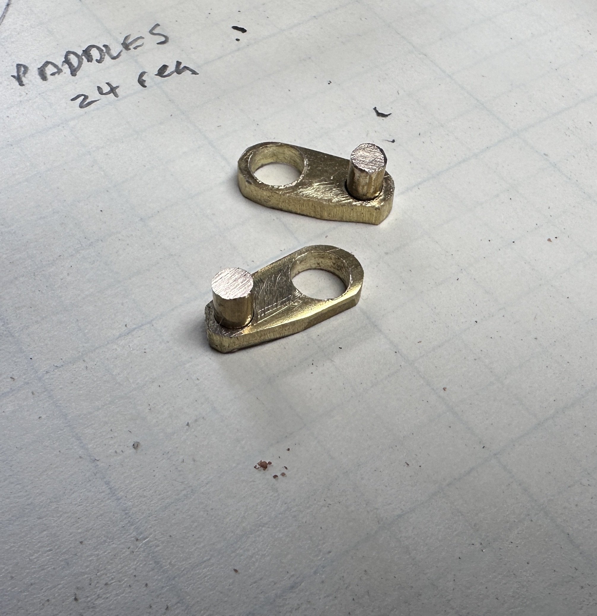
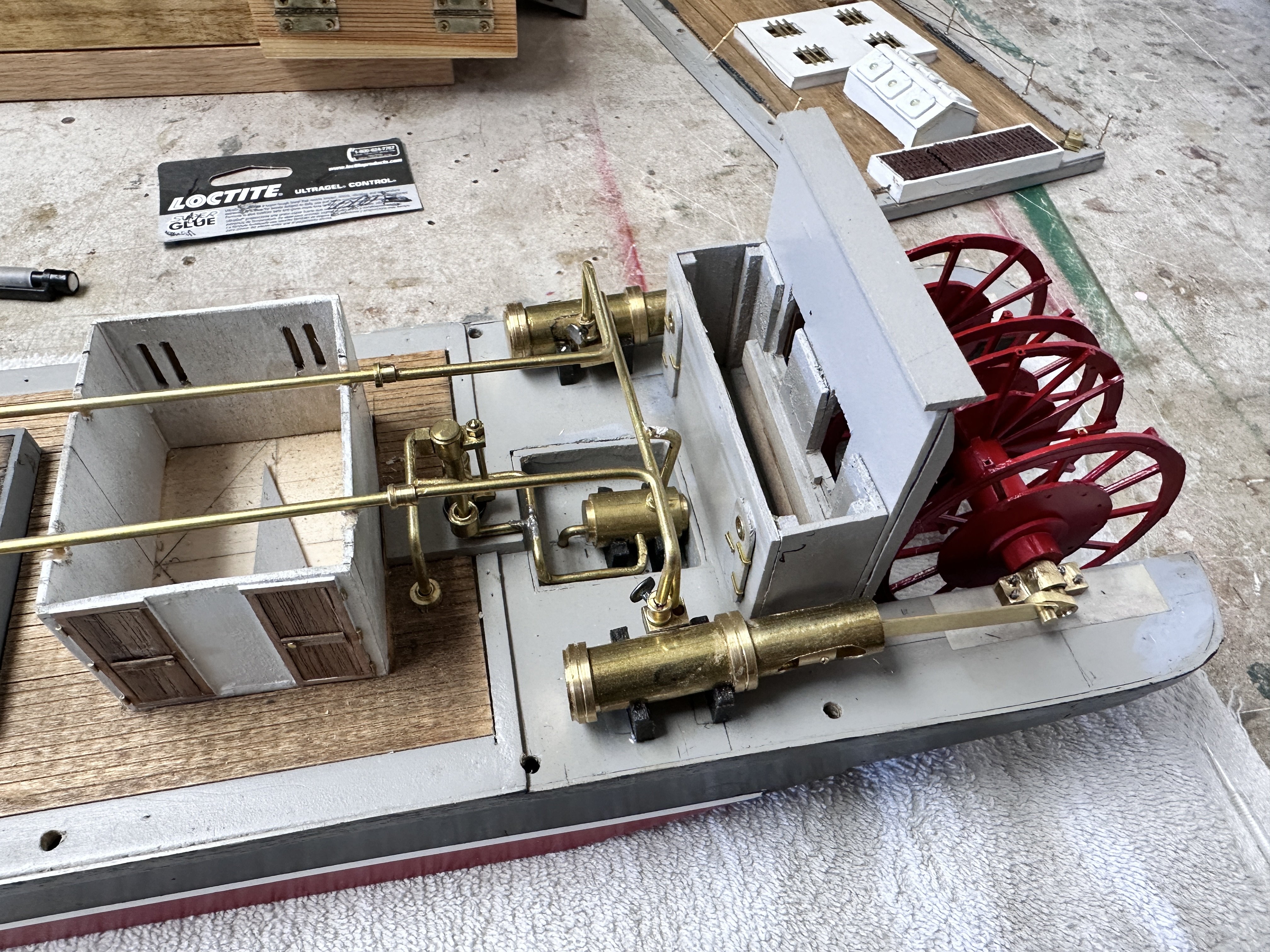
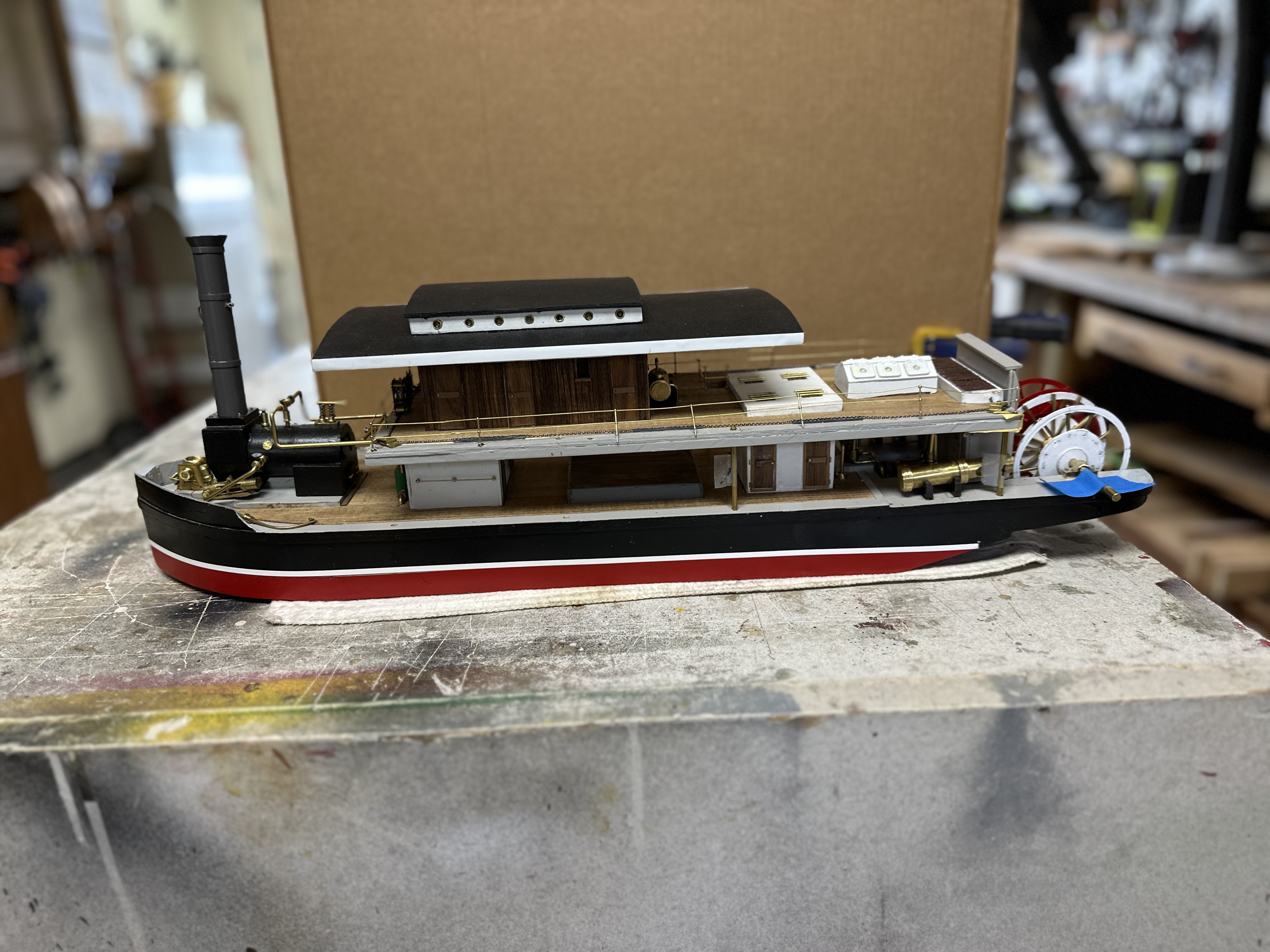
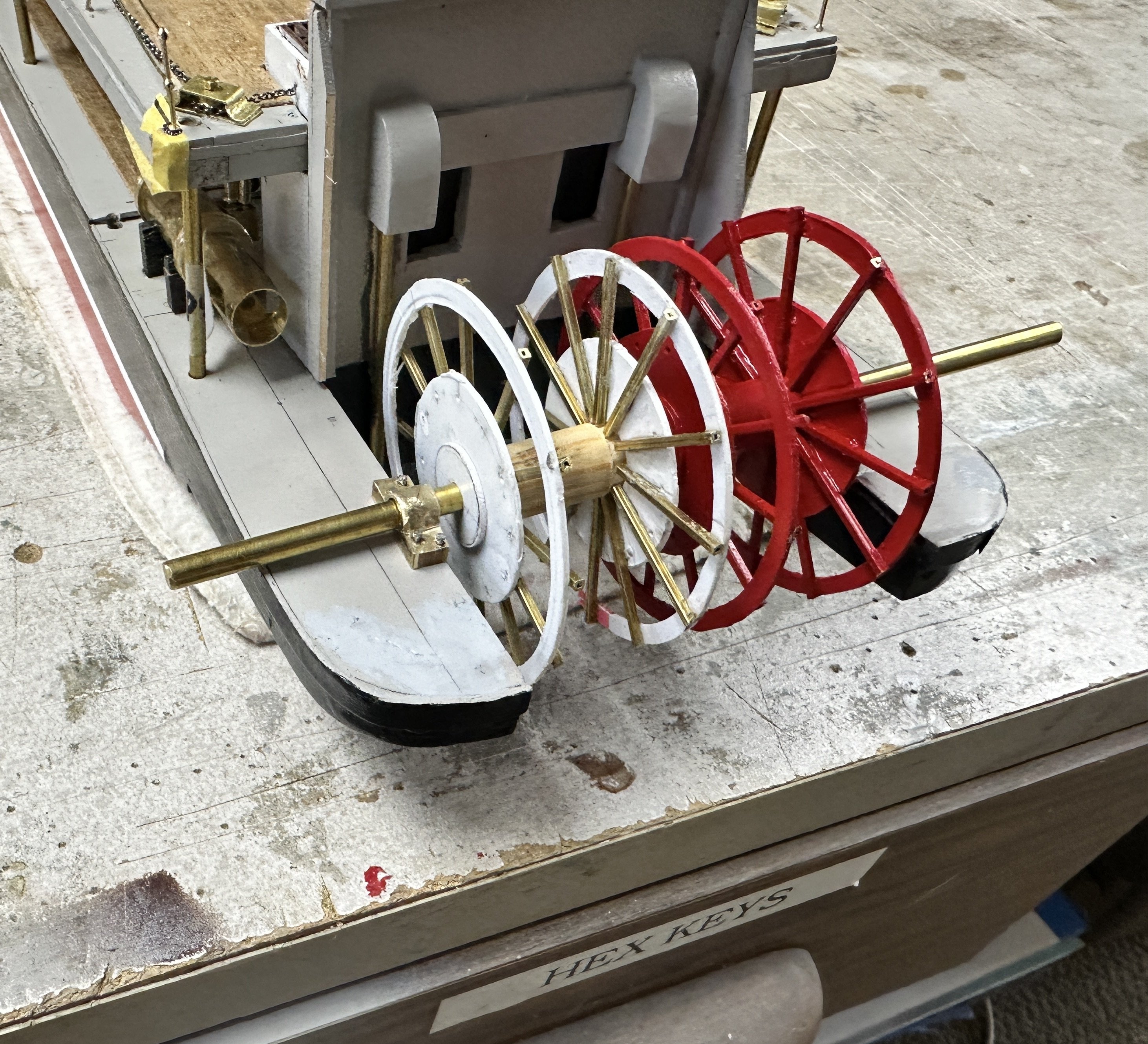
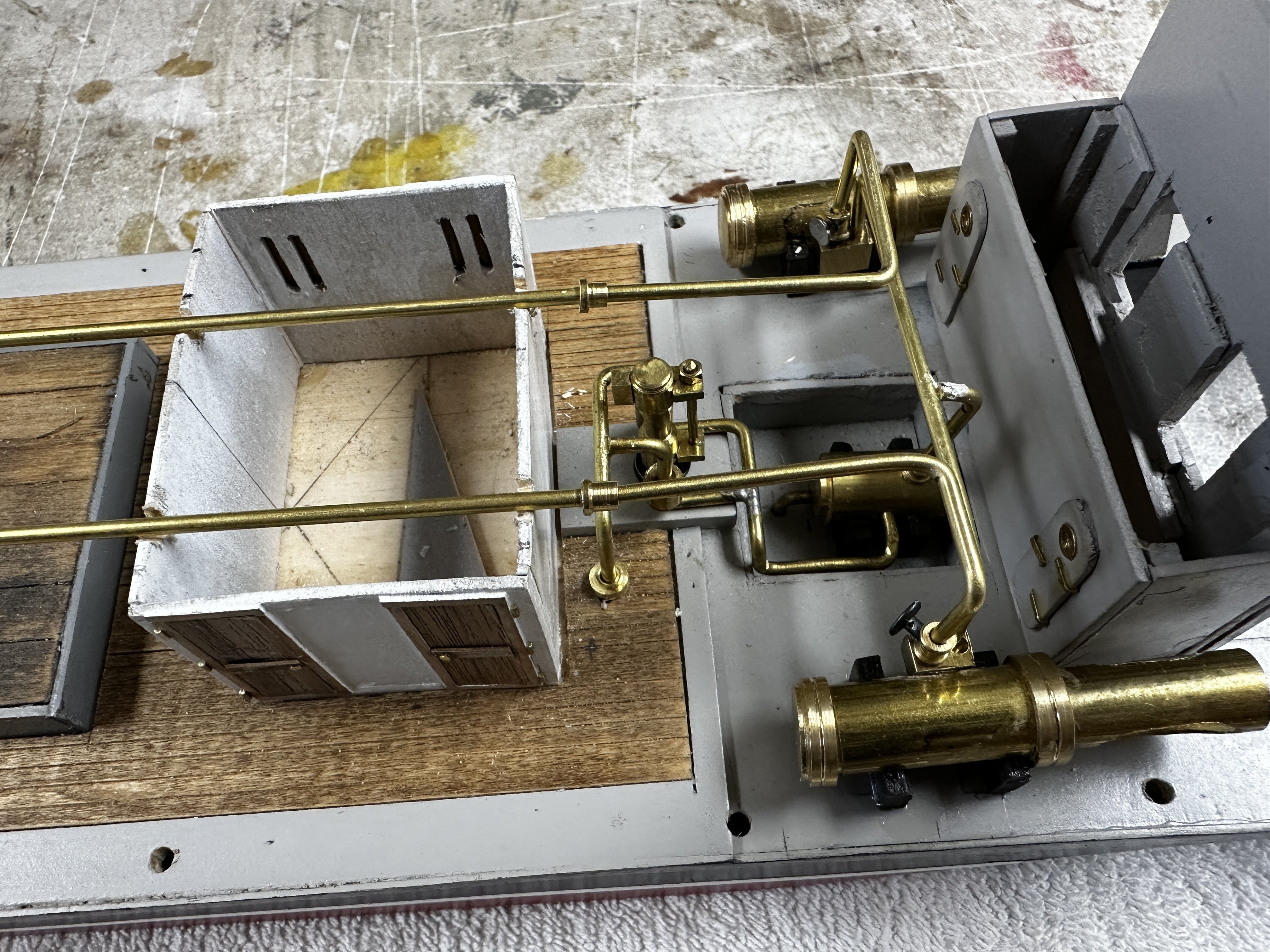
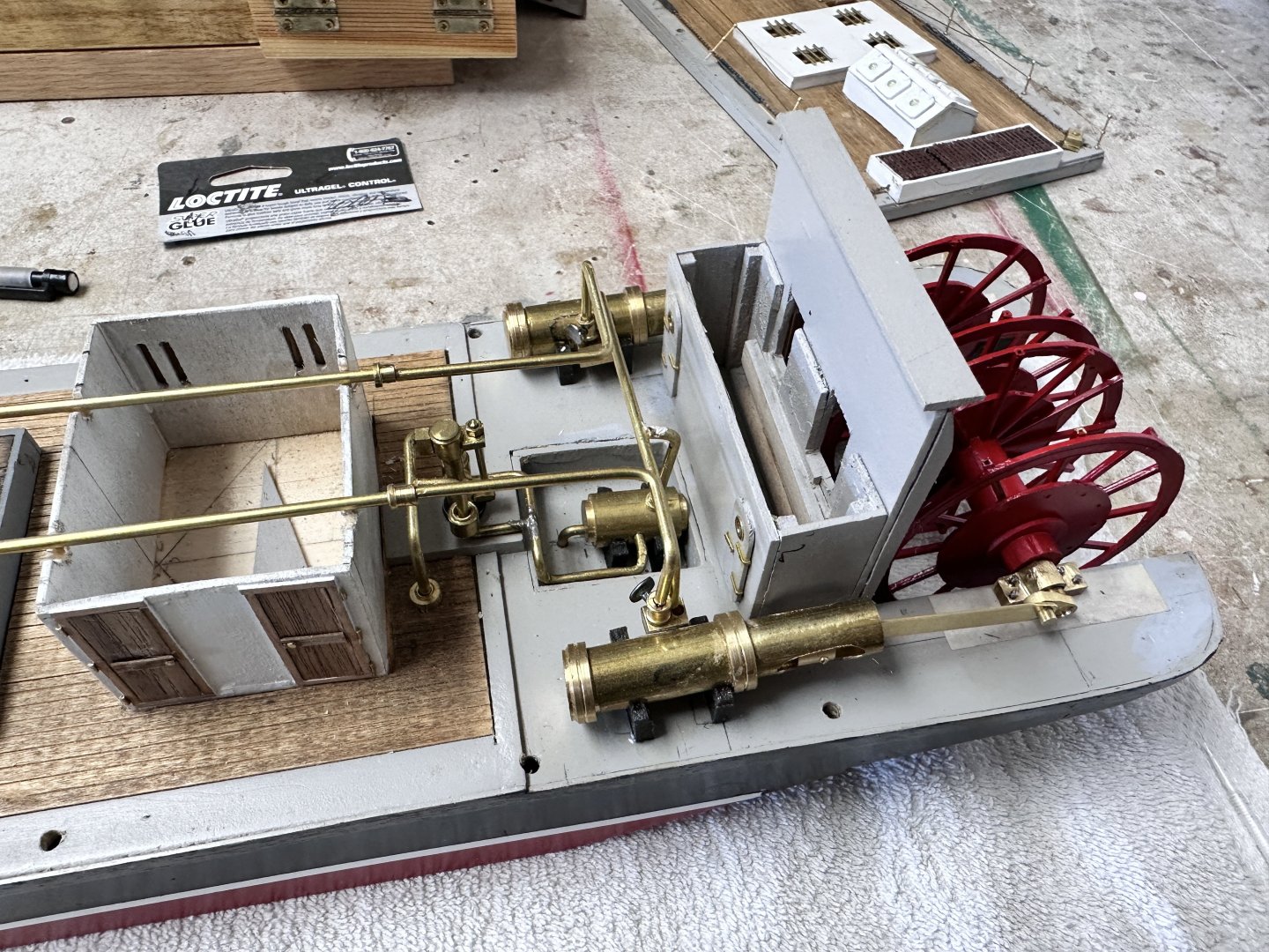
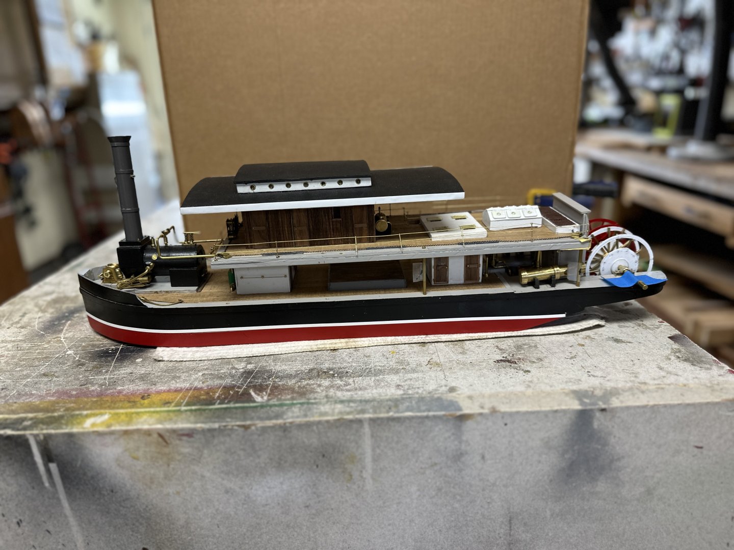
 This is what Zulu will look when all parts are put together. After this photo, the paddles were painted and the engine mechanics and the steam piping was completed . First , the eccectrics. Then the pitmans and the fitting of the cross tree in the engine cylinders. An overhead look at the piping fore and aft. Currently working on installing the buckets (aka paddles) in the wheels. Thanks for the likes and comments.
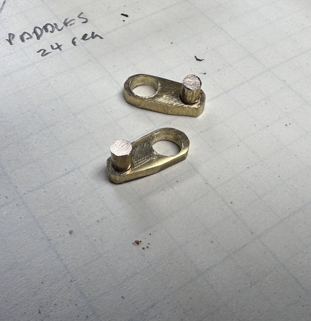
- 128 replies
-
- 13
-

-

-
- zulu
- sternwheeler
- (and 1 more)
-
Thanks to all for the likes. To Keith: I have the same thoughts often but never build anything twice. I take the mistakes as lessons for the future. To Daniel: I joined this forum in 2019. At that time I operated with a +/-1.0mm tolerance. But by watching other people's work I was inspired to try harder and try to control my shaky fingers. I remember and advise from my shooting coach: "aim large = miss large; aim small = miss small". Since then, I have reduced my to tolerance to close to 0.5 mm. I still have to do a lot better to match guys like Valeriy and Wefalk.
- 128 replies
-
- 5
-
-
- zulu
- sternwheeler
- (and 1 more)
-
Great woodwork. Looks fantastic. Regarding the CA, I found that acetone tends to dissolve it. I have used to get metal pieces separated and to wipe set glue from my fingers. Don't inhale too much of it though!
-
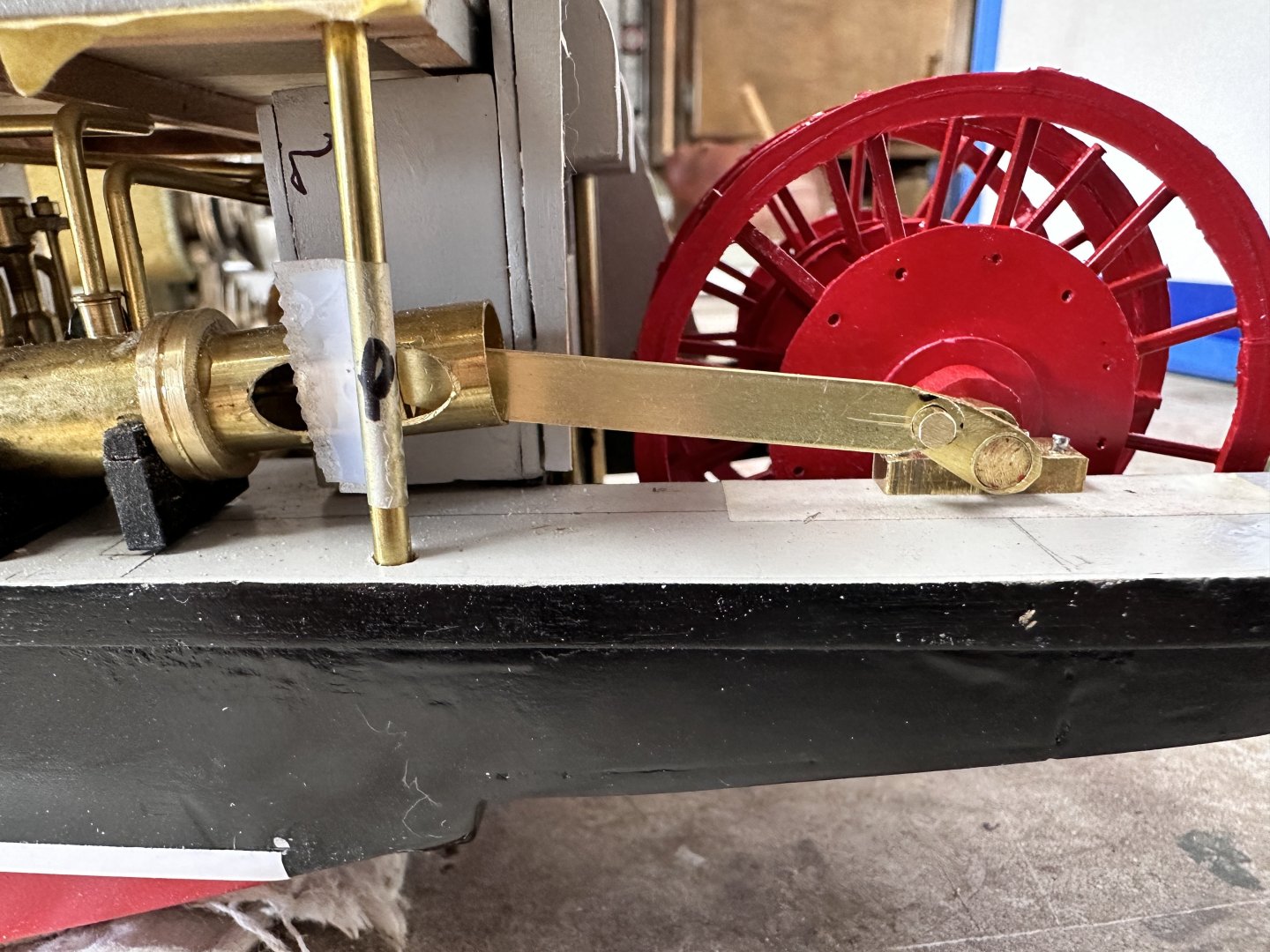
My guess is that each wheel was independent which will be helpful in navigating the narrow Indian rivers. Making the wheels independent gets too complex to make in a static model. I opted to provide the wheels with independent hubs which makes them rotate independently but the eccentrics will be attached to the common shaft. This makes it easy in the static model. Furthermore, While building the hull, I fabricated the sponsons out of a solid piece of wood without taking in consideration the eccentric travel which required an open space below the deck surface. As I said before, poor planning. So now I have two wheels that will rotate independently from engines that will not be capable to complete a revolution. I plan to paint a dark space where the cranks are supposed to get below the deck surface. Again this is a static model going nowhere.😏
- 128 replies
-
- 3
-
-
- zulu
- sternwheeler
- (and 1 more)
-
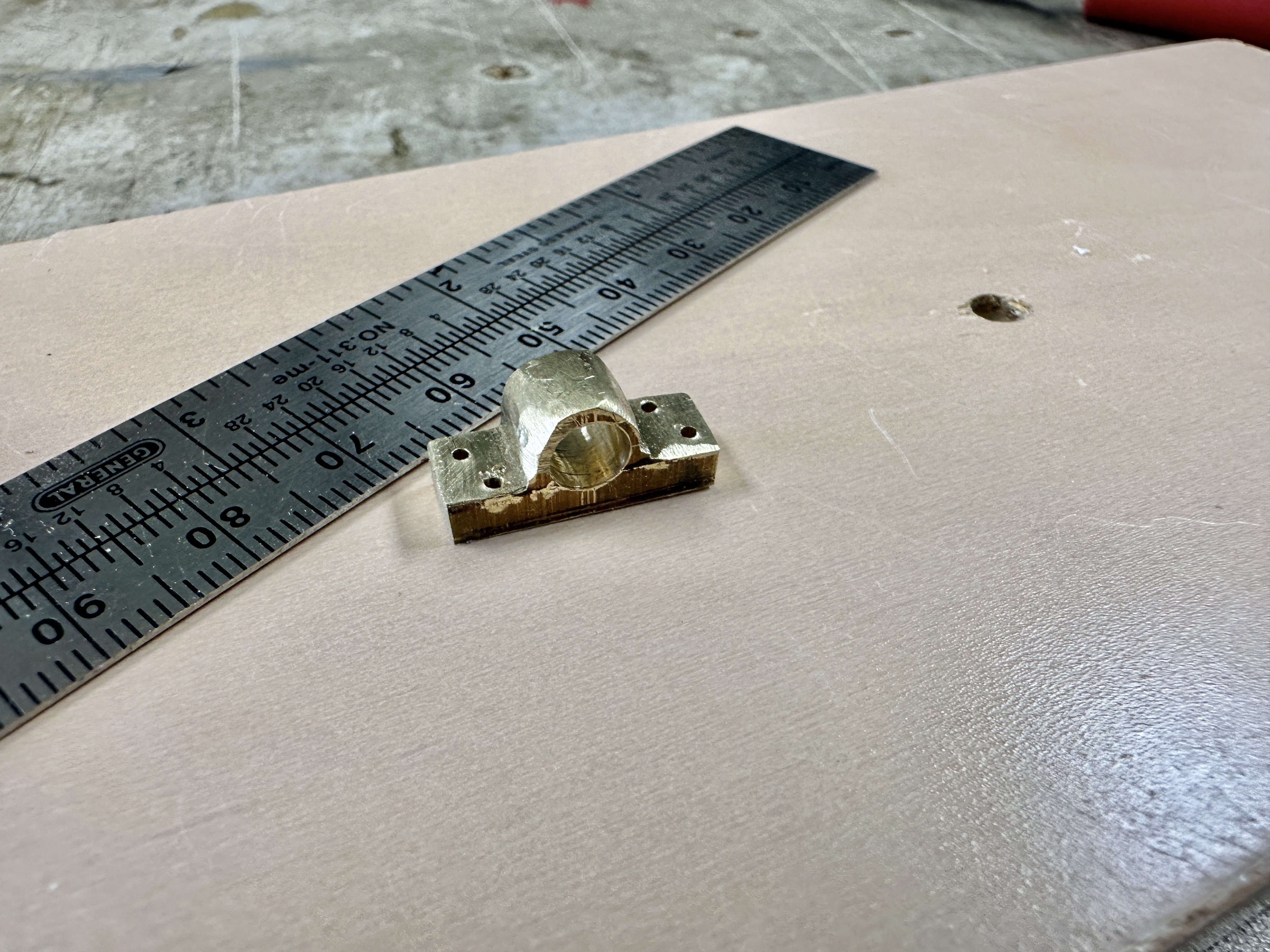
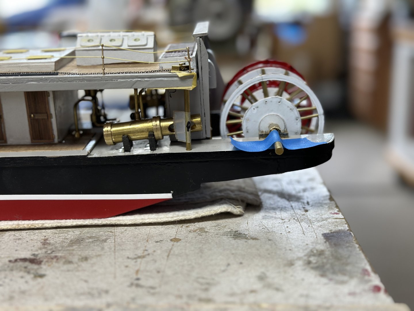
The paddle wheels are done and we are now working on the assembly. One of the the main bearings And the assembly presented to the sponsons. Now working on the eccentric cranks and the pitman connecting rods. Then finally add the paddles or what I have seen elsewhere called: the buckets. In September it will be one year since I started this model. It has been a wonderful experience and big lessons have been learned. Most important is to plan the order of the assembly to avoid interferences. In this model I added the railing way ahead of the bulk of the deck furnitures and now I am faced with having to redo it after damaging the fragile wires.


- 128 replies
-
- 10
-
-
-
- zulu
- sternwheeler
- (and 1 more)
-
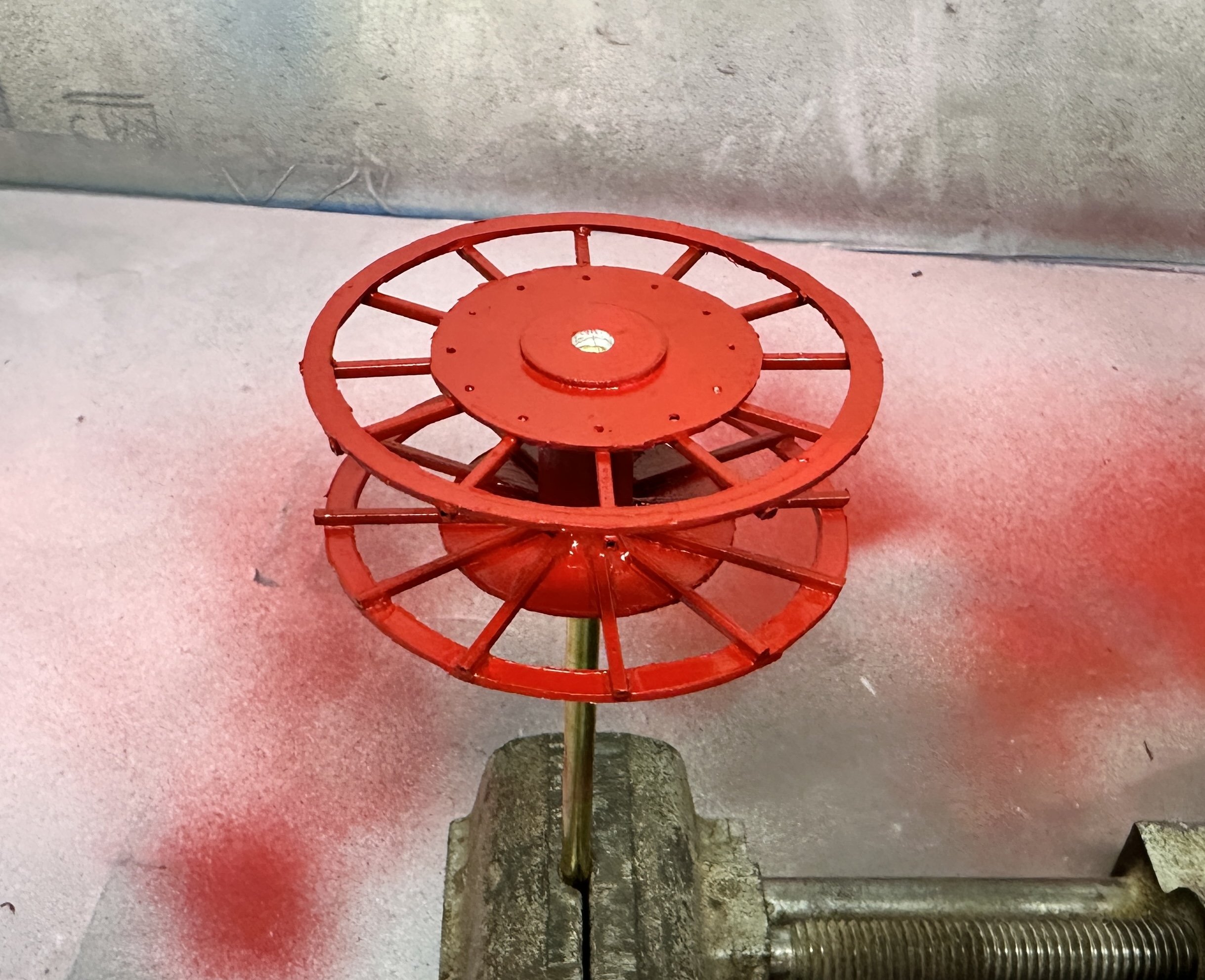
Keith, The only information I had on this ship was an article in Model Boats in April 1982. I have tried to get the other two issues to no avail. The drawings from Ray Vine indicated that the paddles were gloss red and the frame gloss green but I decided to follow the USA practice of having the whole paddle wheel in red.
- 128 replies
-
- 3
-
-
- zulu
- sternwheeler
- (and 1 more)
-
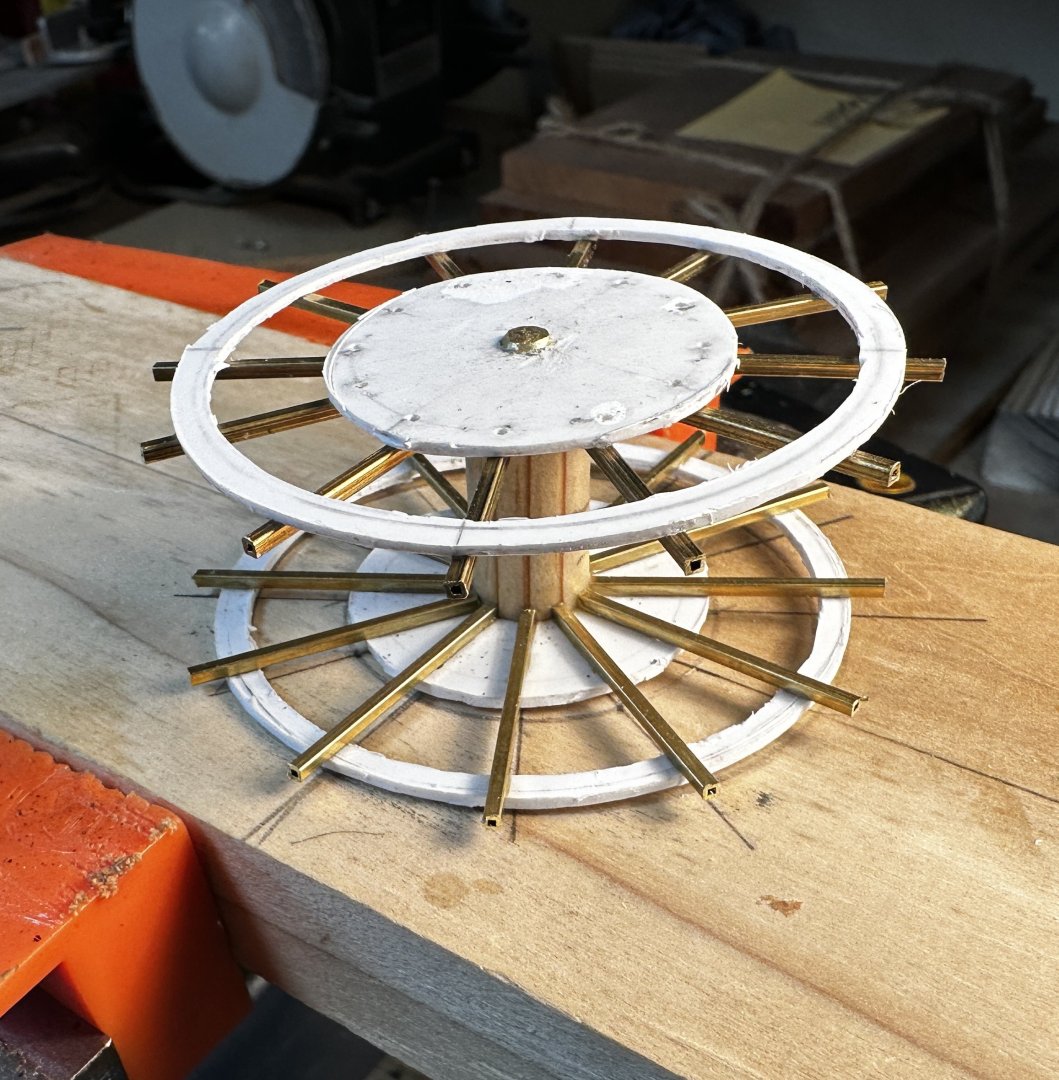
Work continues on the paddle wheels. Following is the first wheel assembled sans the paddles.

- 128 replies
-
- 7
-
-
- zulu
- sternwheeler
- (and 1 more)
-
Wefalk, I love you research.
-
I admire your work. Count me in on this one.
-
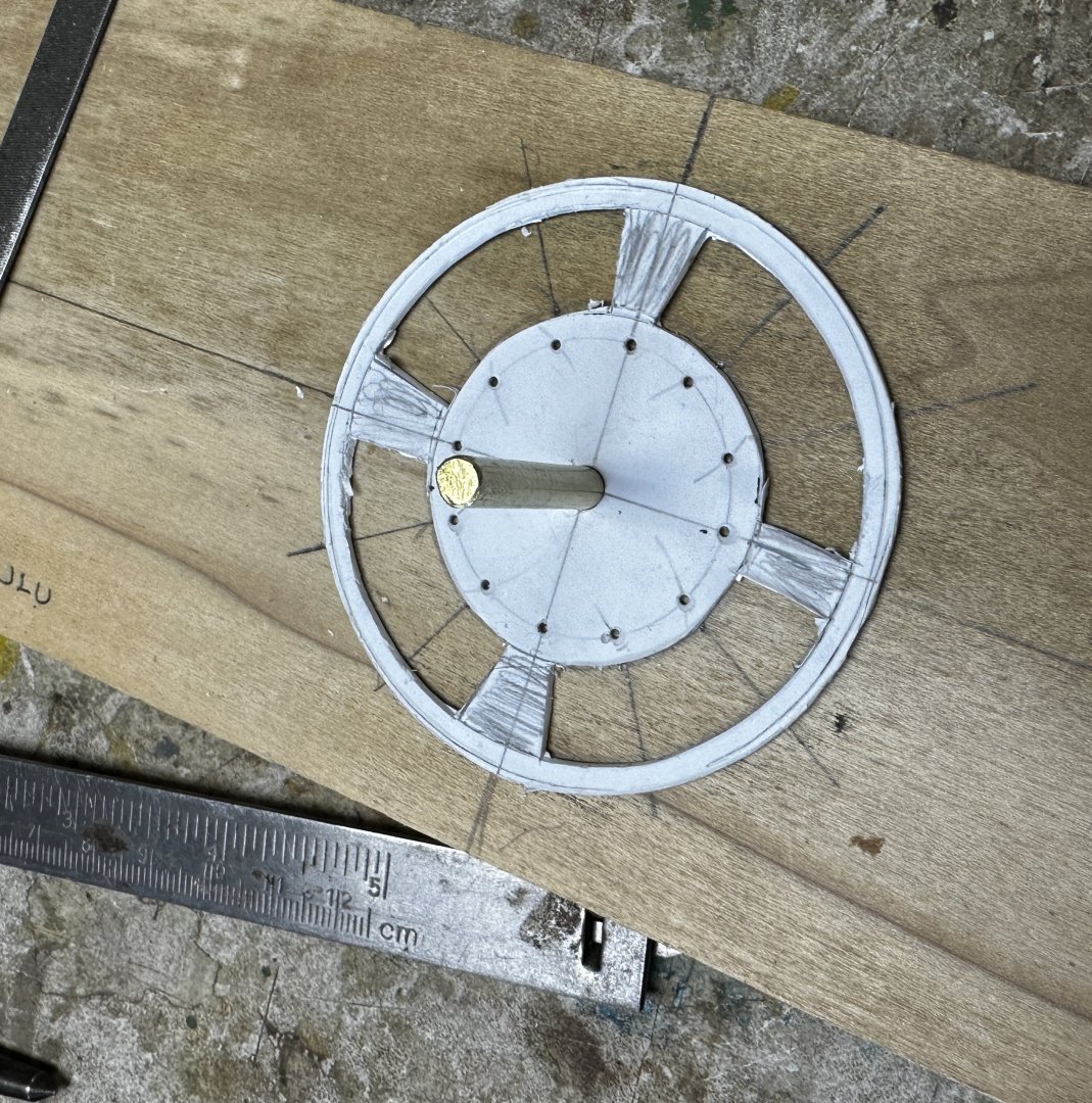
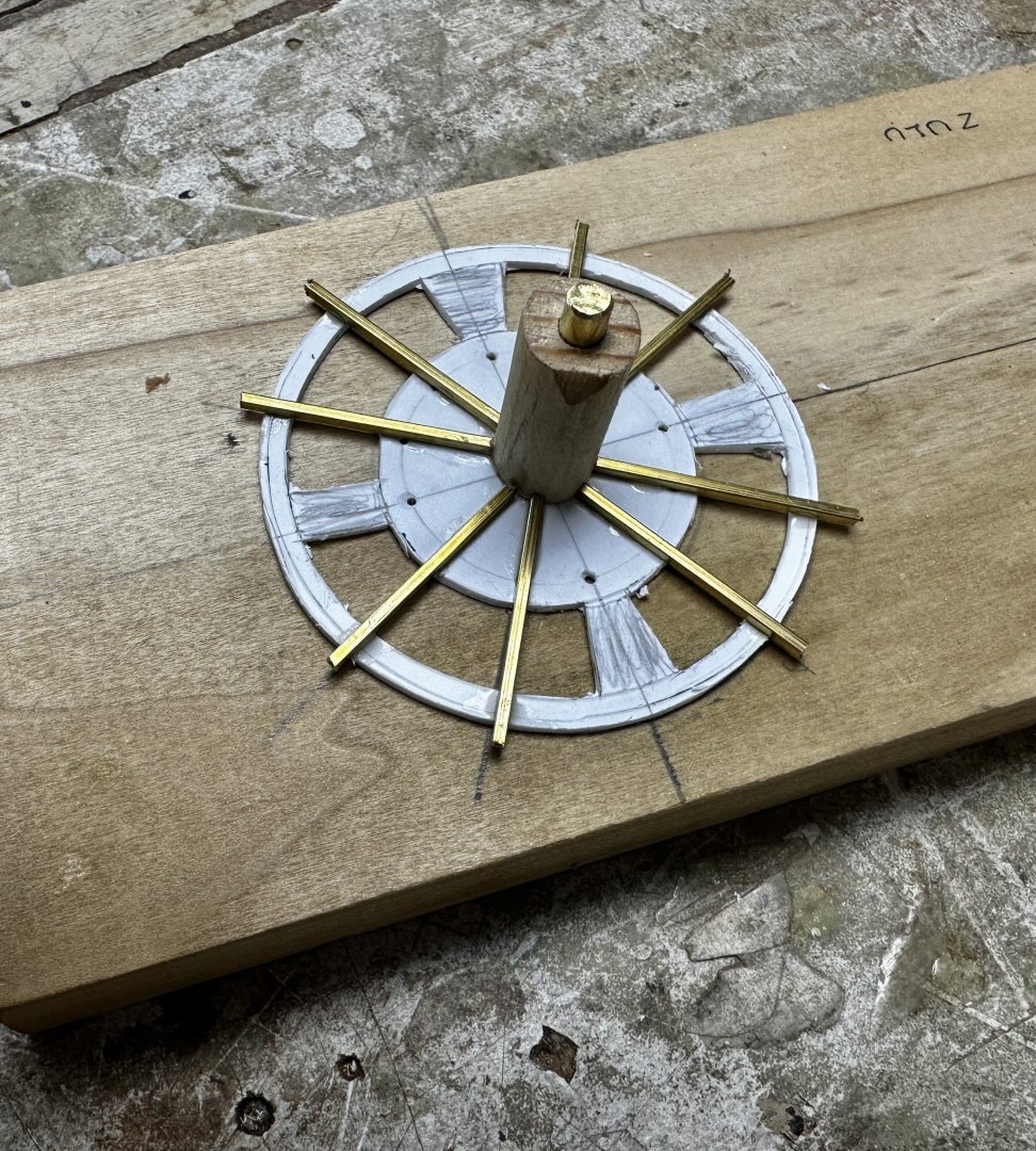
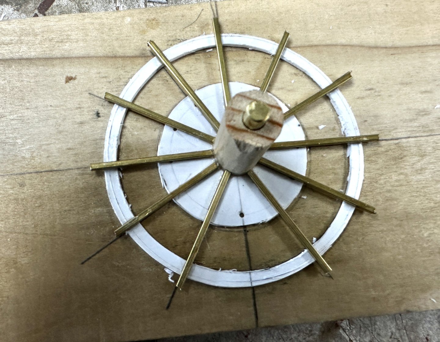
Continuing the paddle construction. I cut out the space between inner and outer circle. But, trying to maintain concentricity between both circles I left four radial pieces uncut. The spokes and wood hub were then added. Once that was completed , the holding webs were cutout and replaced withe rest of the spokes. And following is a rough look how the paddle wheel will look. What is shown above is a combination of port and starboard parts just for looks. The spokes on each side must be perfectly aligned in order to accept the paddle boards. I will be using the method that Cathead used in his Peerless build. TO BE CONTINUED
- 128 replies
-
- 7
-
-
-
- zulu
- sternwheeler
- (and 1 more)
-
I knew about the feather wheels and that's why those wheels presented by Wefalk are so incredible perfect at a small scale. Just figure out how many minuscule pieces need to be fabricated. And all these by a guy 90 years old. BTW, I am 88 years old.
- 128 replies
-
- 2
-
-
- zulu
- sternwheeler
- (and 1 more)
-
Wefalk, wow, those are paddles. But, unfortunately I am not at that level yet. Those wheels are absolutely perfect. Keith, The plans I have been using are from an old issue of the Model Shipwright. If you look at the plans at the beginning of my post you will see that they were designed for R/C. It shows using an electric motor and a worm gear drive for the paddles. The plans could be enlarged to something like 1/35 or even larger 1/24. They would make a beautiful sight in the ponds. If you are interested, you could send me your address and I will mail a set to you.
- 128 replies
-
- 2
-
-
- zulu
- sternwheeler
- (and 1 more)
-
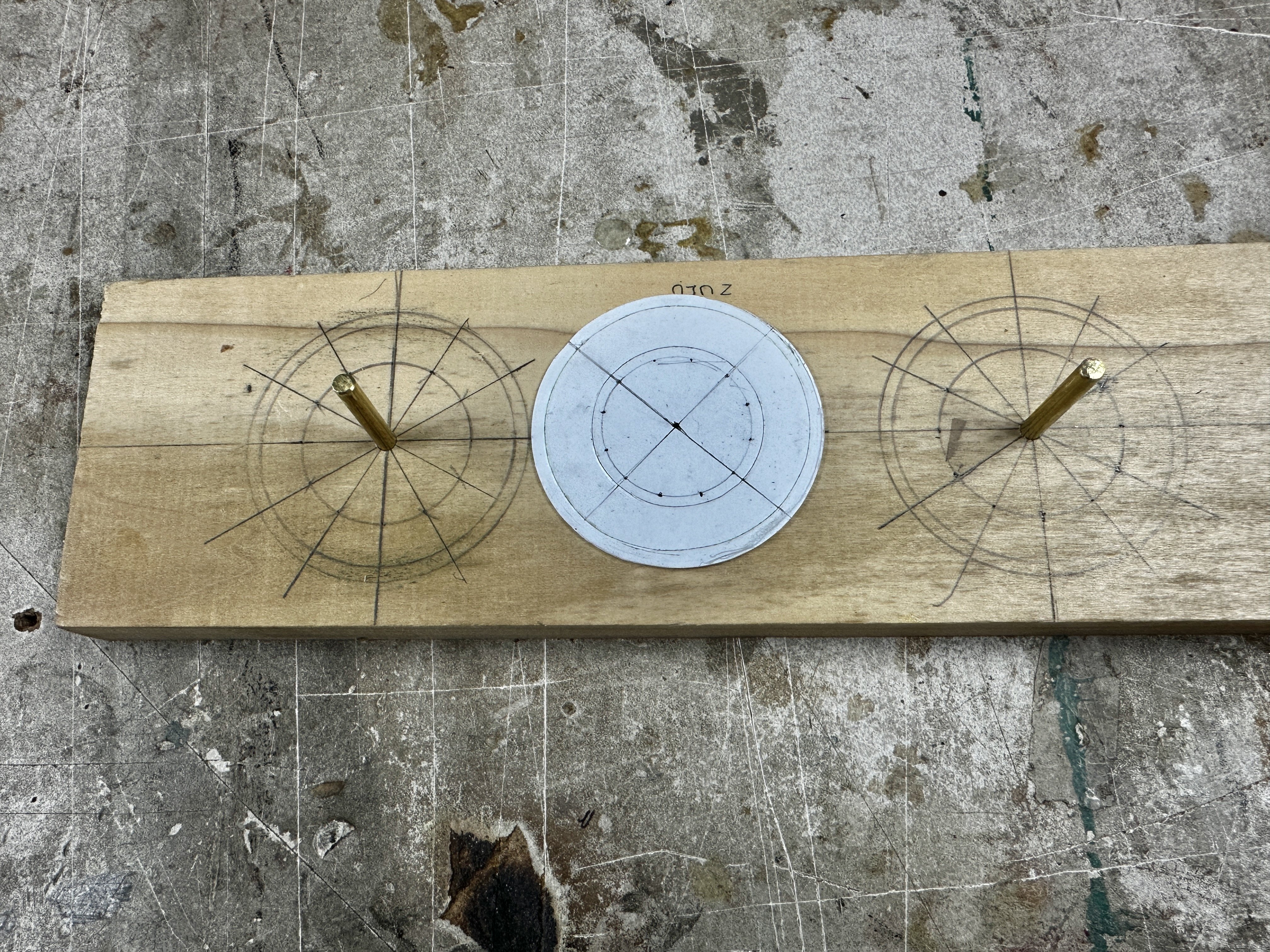
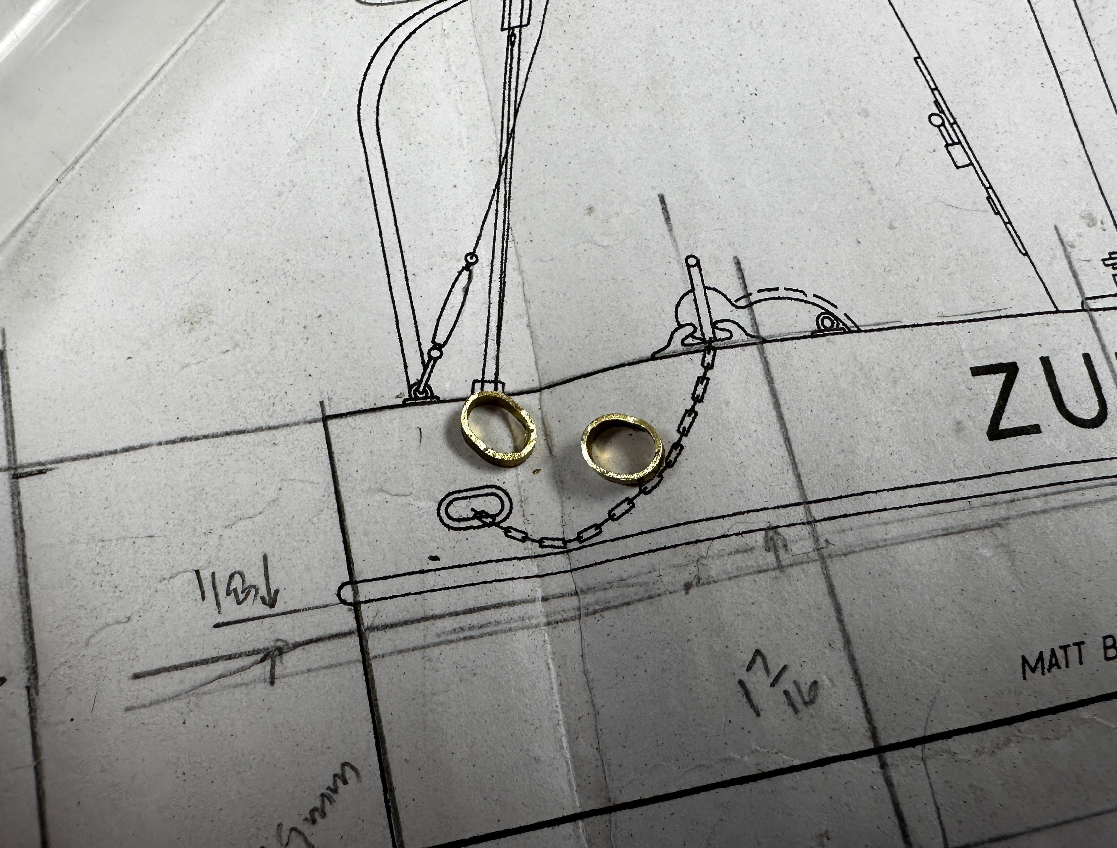
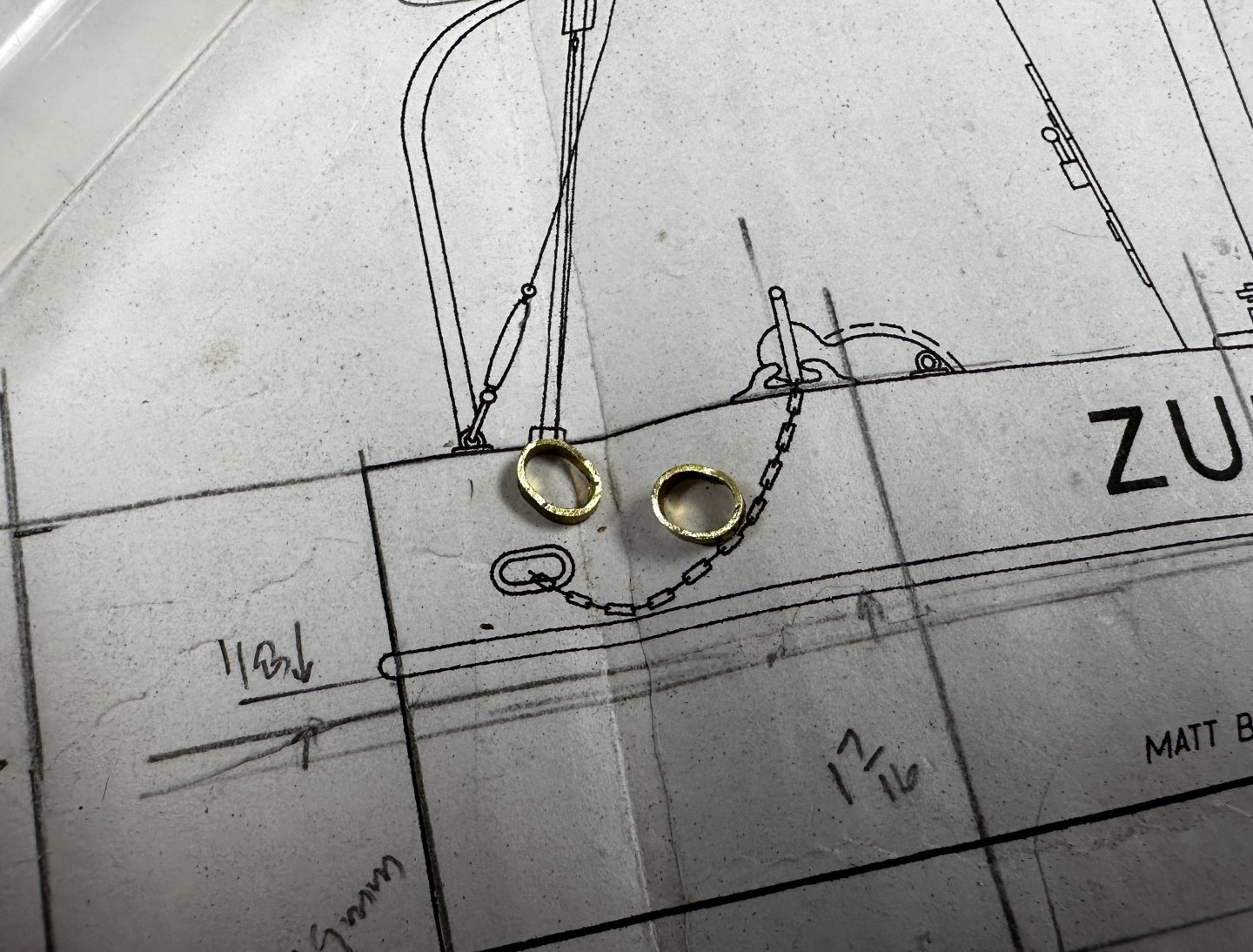
Zulu is almost complete. It is time to start the last big item: the paddlewheels. I have looked through the forum at different methods to fabricate these wheels and the one I like most was the one used by Cathead in his Peerless. But, Zulu was a ship made in England, then disassembled and shipped to India where it was put together. And the plans show the wheels made with metal rims. Thus, I decided to use a method similar to one I used to assemble my Bianchi motorcycle spoke wheels. The rims will be made from 1 mm styrene sheets and I will use some 1 mm brass square tubing. Following is the jig and the first rim before cutting it through. To be continued.

- 128 replies
-
- 6
-
-
- zulu
- sternwheeler
- (and 1 more)
-
Keith, I did exactly the same process by setting the two opposing sides on the board with the double sided tape. But my tape was not that strong and it made a mess when trying to get it through the saw. By using a little more wood I managed to make the parallel cuts. Been very interesting to explore all these fabrication methods.
- 128 replies
-
- 4
-
-
- zulu
- sternwheeler
- (and 1 more)
-
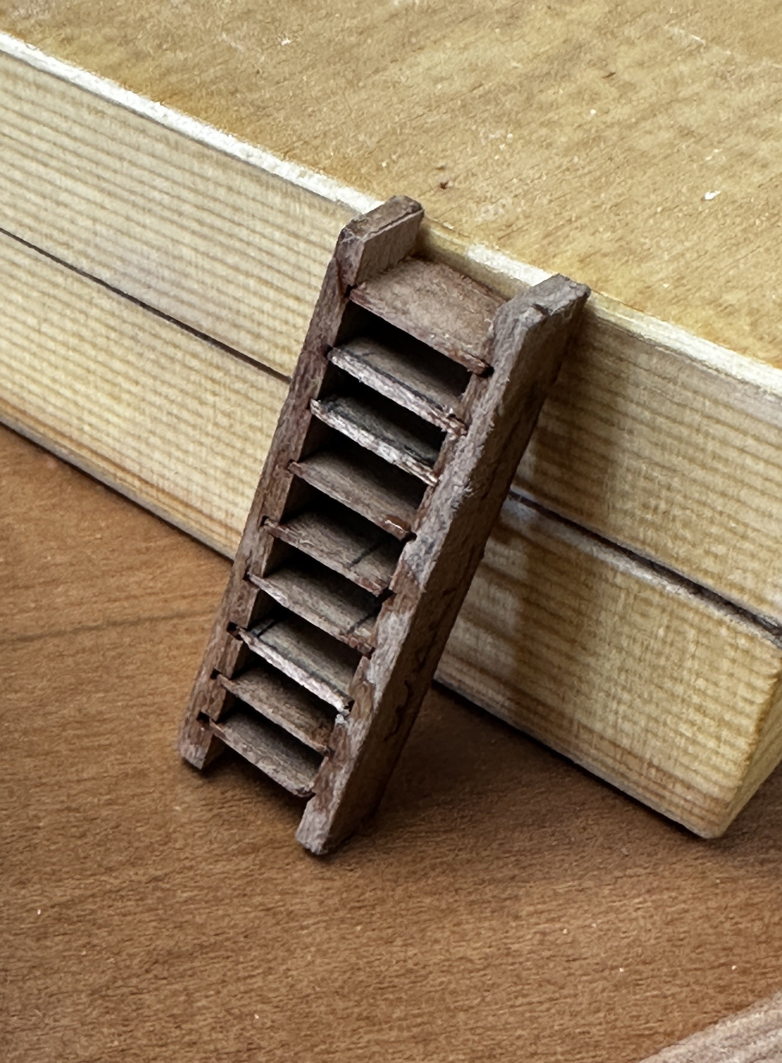
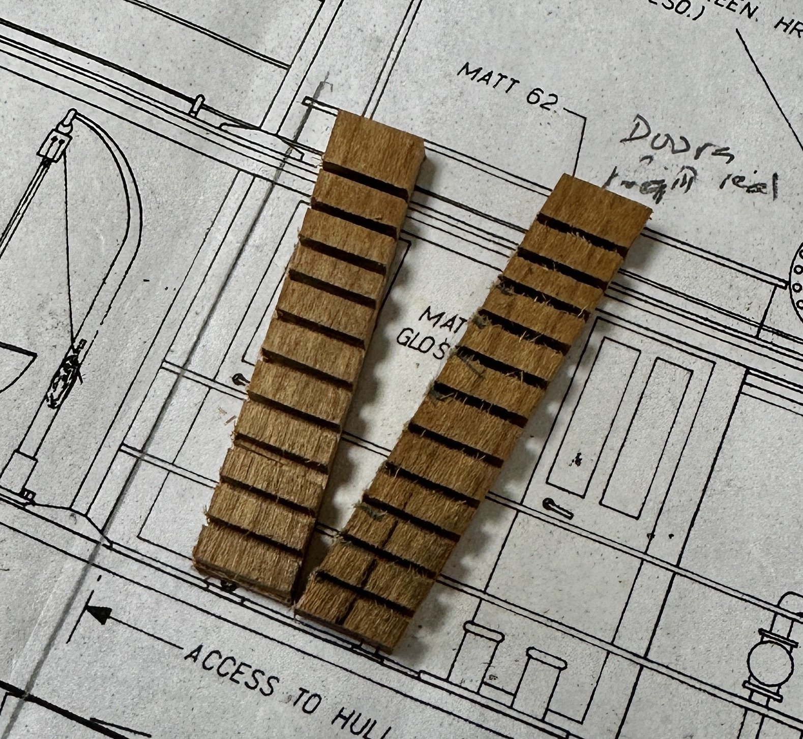
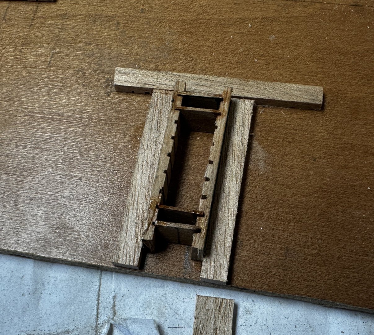
I may have missed something in Keith"s jig so, after a lot of thinking, I figured how to be able to cut the notches for the steps at the same time on both opposite sides. Cutting the angled sides was a little troubling in my micro saw because of the extreme angle but I managed to do it using MicroMark's "taper jig". To change from right to left I disassembled the jig and turned it over. Pictures of the new ladder will follow soon. BTW, the reason I was doing another ladder is because the first one (post #64)came out one step short when I tried it the model. Sorry, senior moment😪
- 128 replies
-
- 4
-
-
-
- zulu
- sternwheeler
- (and 1 more)
-
Keith, I see, your jig actually carries the two sides at the same time on the same setting of the fence. Outstanding! Your method is now in my list for future ladders. This why I enjoy this forum so much.
- 128 replies
-
- 3
-
-
- zulu
- sternwheeler
- (and 1 more)
-
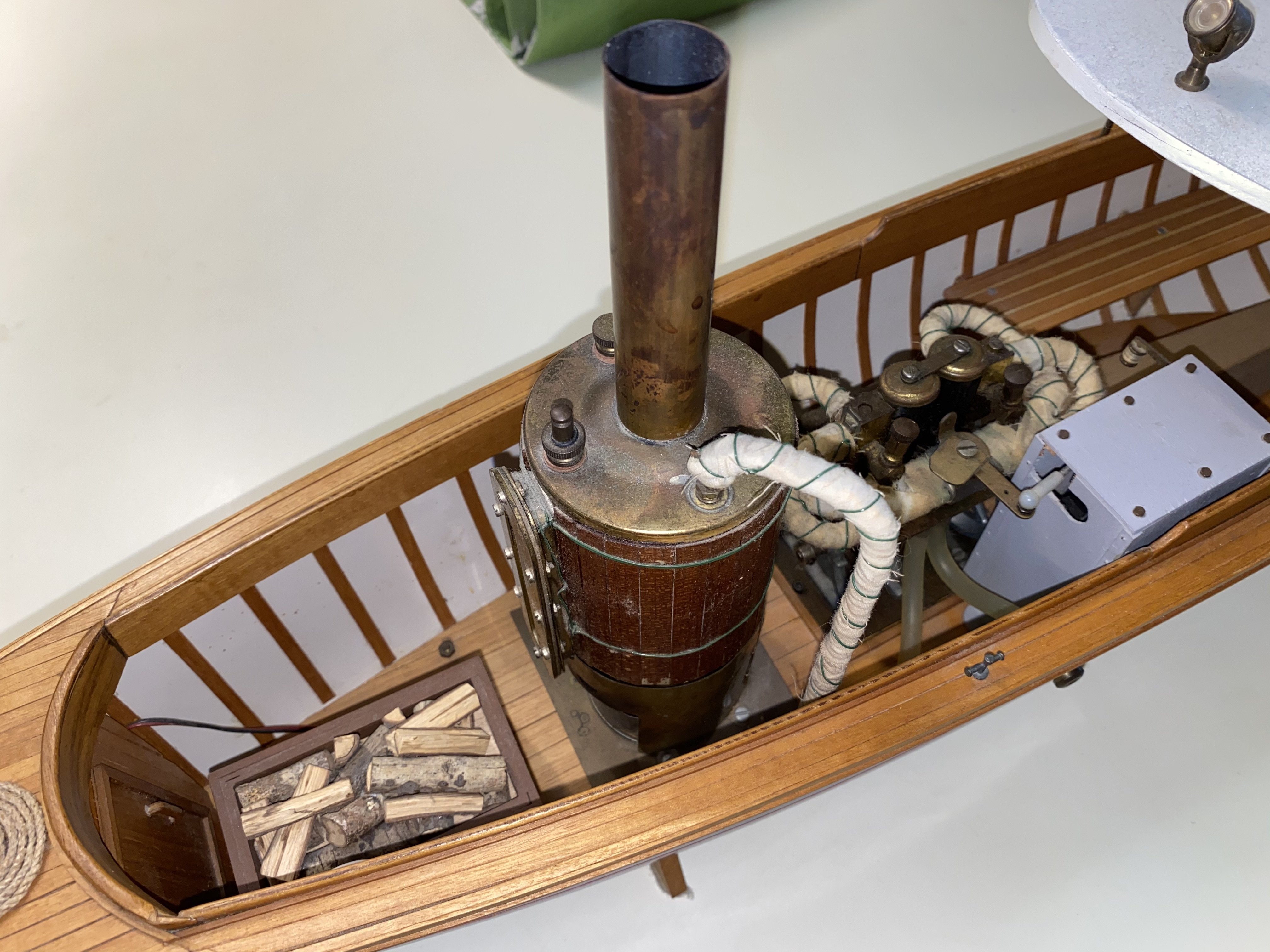
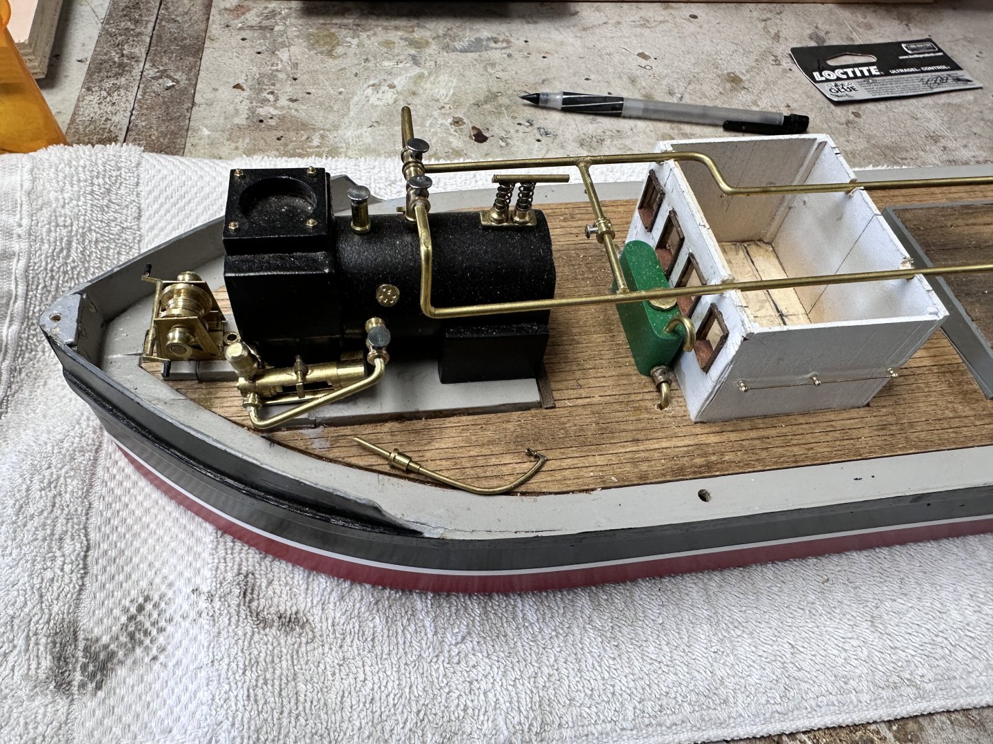
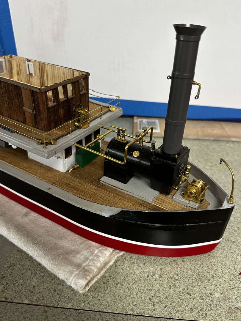
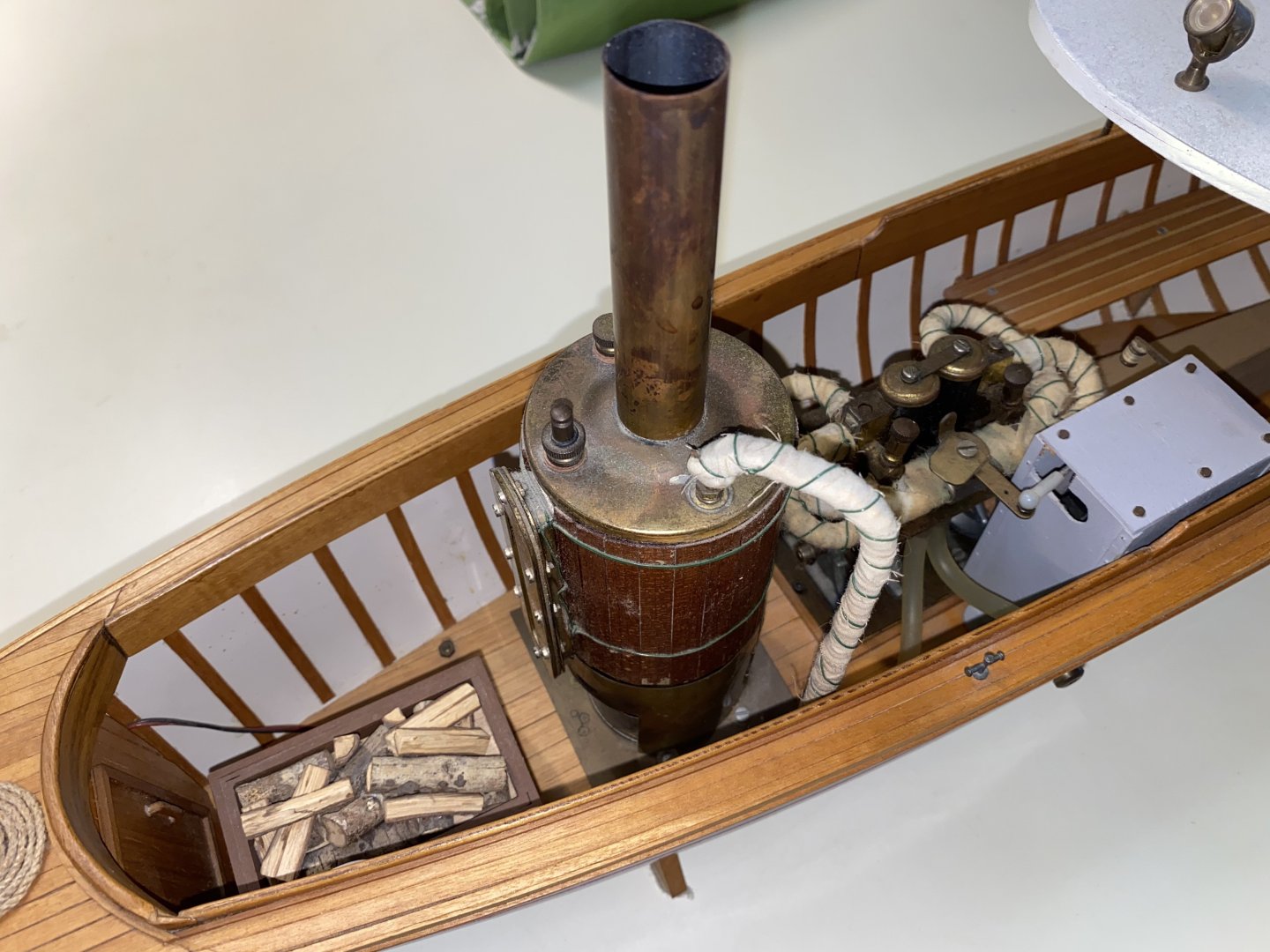
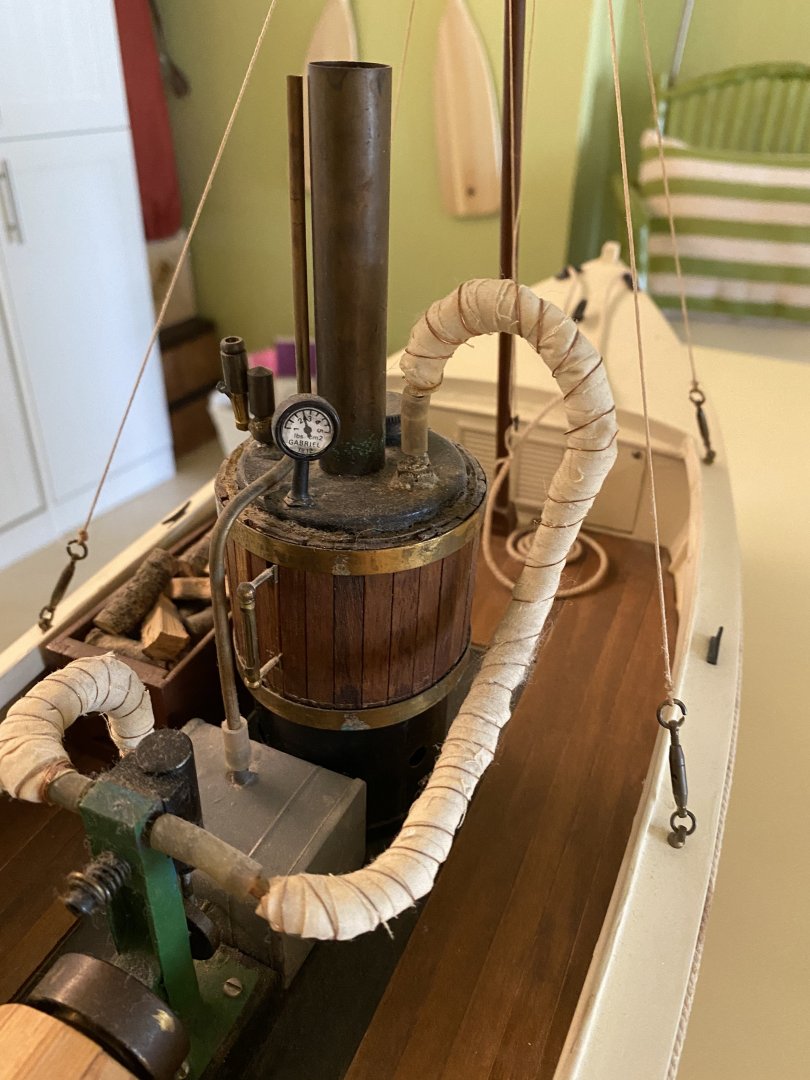
Keith, I when to looked at your Germania and I have to congratulate on that model The hull is exquisite. Regarding the ladders, Ken Kenny's system uses a long piece for the sides of the ladder and then sets the miter gage to the stair angle. The blade is set to half the thickness of the side strip. One side is cut and the miter angle is reversed and a new see of steps is done. The strip is advanced just like for making a box joint. This is the video: I have used this method several times and for the Amapá, I used card stock for the steps. Using Wefalk advise ,I shellac the card stock. In this scale I used 1/32 thick strips. I did some more work on the model as shown in the following photos. The piping forward is completed and the stack painted dark grey as per the forum's advice. I wish I have done that for the boiler too. The engine piping is complete. I finally, my latest micro work: the anchor hawser pipes: Thank you for your comments, advice and likes. I have learned so much watching you guy's work. Thanks.

- 128 replies
-
- 11
-
-
-
- zulu
- sternwheeler
- (and 1 more)
-
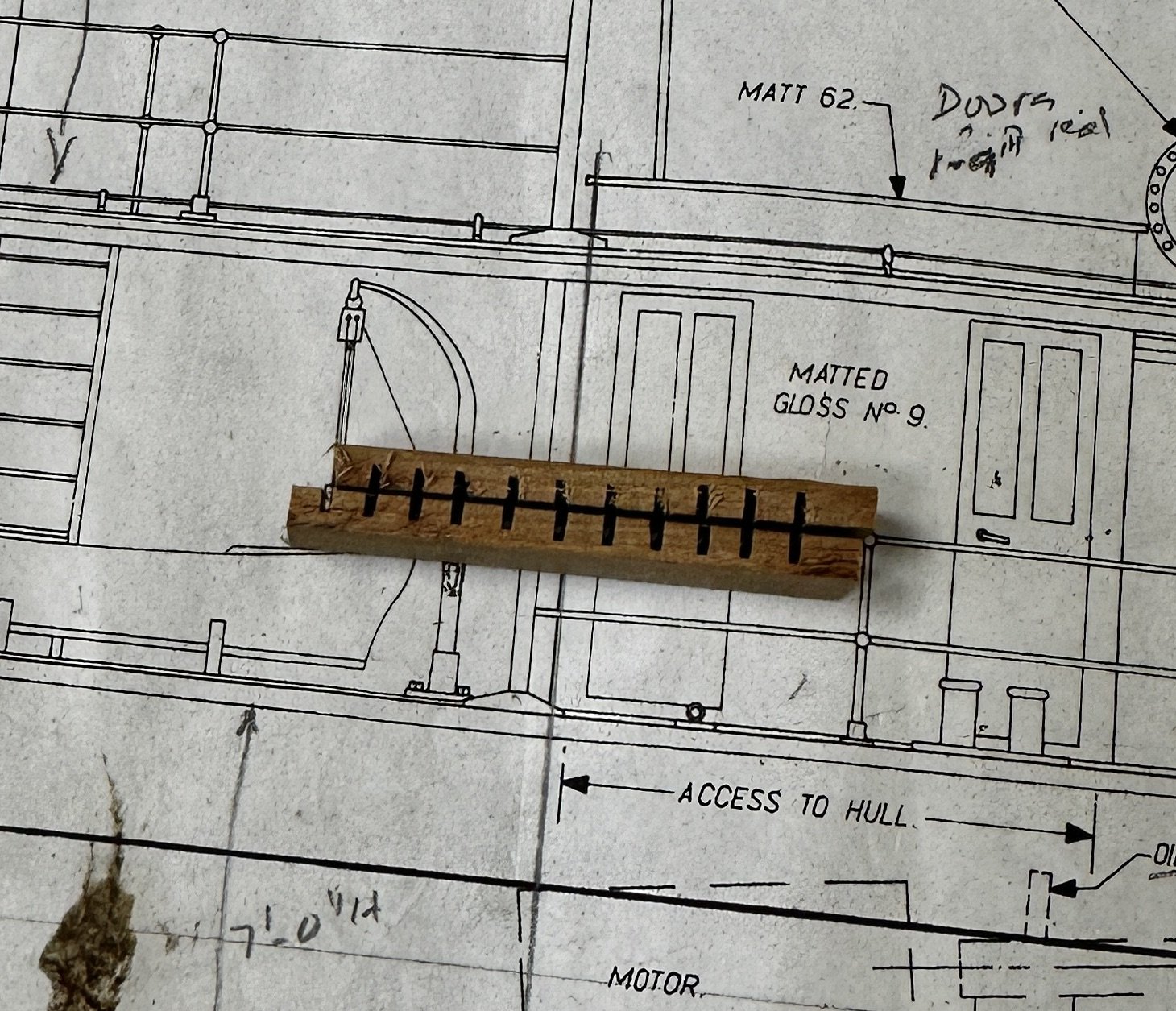
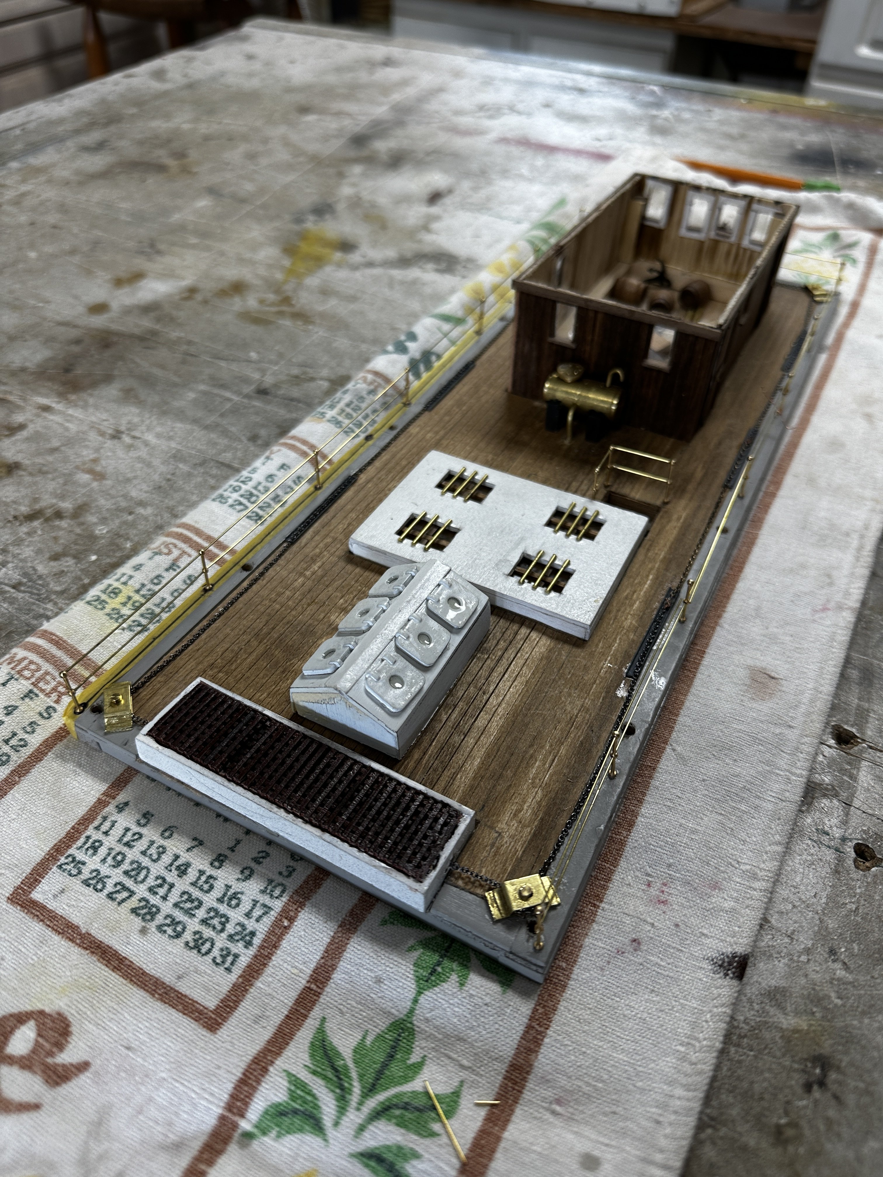
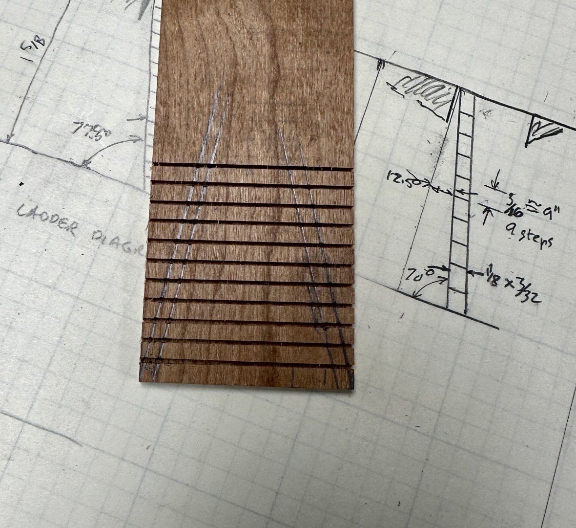
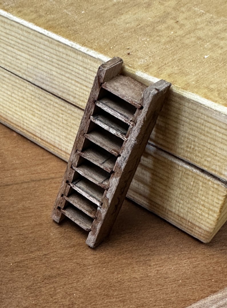
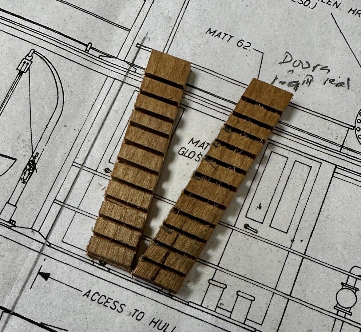
A little more progress. I worked on the stairs from the main deck to the boiler deck. I used a system that I learned from Kevin Kenny's building of the Naparima. The method uses the mini saw with a kerf that matches the material for the steps, in this case, 1/32". Then I used jig to insert the steps. And this is the unfinished ladder. The finished stair will have handrails and a thinner profile.Then it will be painted

- 128 replies
-
- 10
-
-
- zulu
- sternwheeler
- (and 1 more)
-
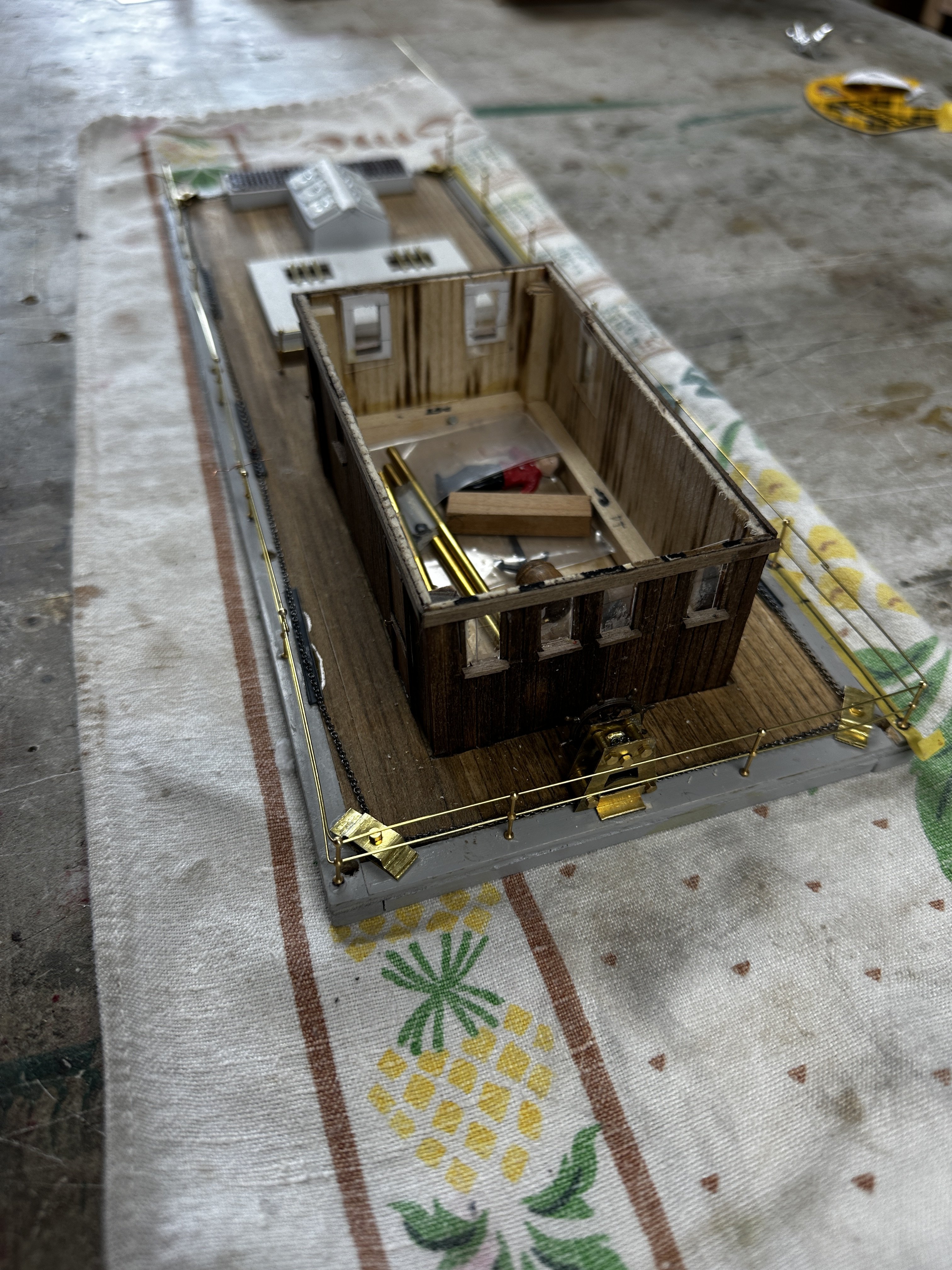
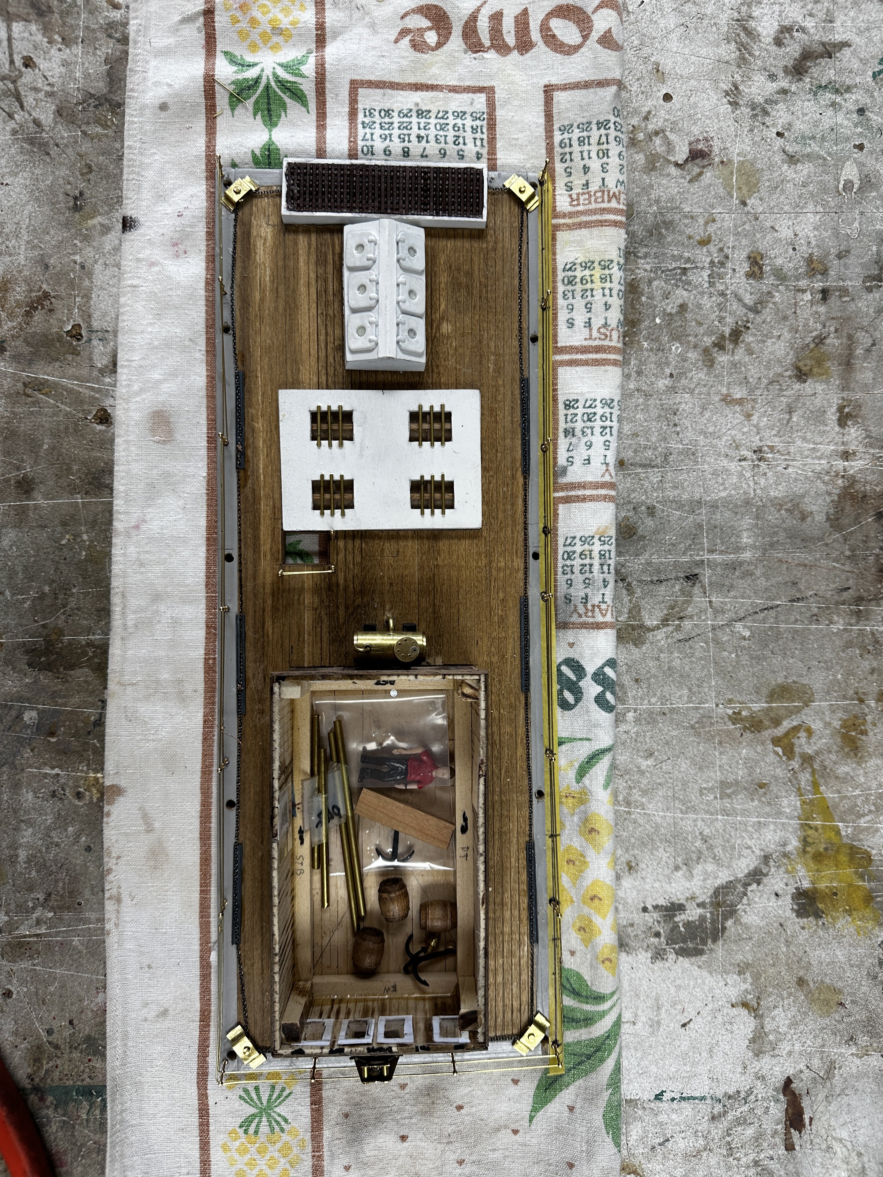
The boiler deck completed. Continue work on engine piping. Thank you for your comments and likes.


- 128 replies
-
- 10
-
-
-
- zulu
- sternwheeler
- (and 1 more)
-
Ives, I make these models for my own pleasure and to share it with friends. My fun is in the research and of the planning. Then comes the challenge of the fabrication procedures and I am more a mechanic than a carpenter or a painter.
- 128 replies
-
- 4
-
-
- zulu
- sternwheeler
- (and 1 more)
-
Keith, I try to leave the brass shinny because it attracts the eye to the metal work. I enjoy working with brass specially the lathe work.
- 128 replies
-
- 5
-
-
- zulu
- sternwheeler
- (and 1 more)
-
Keith, thanks for your suggestion. Regarding the lagging, I considered it. I did it on two of my R/C models with live steam propulsion. But, those models were at a much larger scale. At my scale with a 3/32" in pipe it will be quite a task. Since I started this forum my tolerance has improved from +/- 1.0 mm to 0.5. My hands and sight are reaching its limit. This is my Patricia at 1/12 scale: And this my African Queen at 1/24
- 128 replies
-
- 3
-
-
- zulu
- sternwheeler
- (and 1 more)