Ras Ambrioso
-
Posts
662 -
Joined
-
Last visited
Content Type
Profiles
Forums
Gallery
Events
Everything posted by Ras Ambrioso
-
 CDW, I will be there to follow your re-build. I often thought of reworking those Burago car models but I was afraid to ruin such beautiful models. So you may inspire me to try. Great job on your Honda.
 -
Congratulations. Fantastic job CDW and agree with with that there is a point when you have to stop and move on.
-
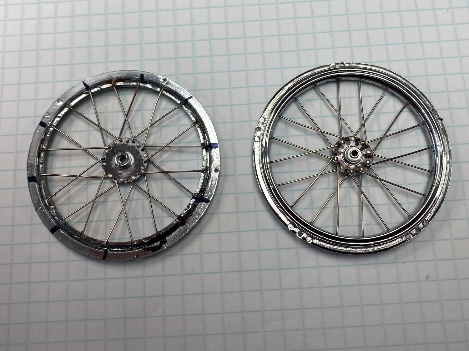
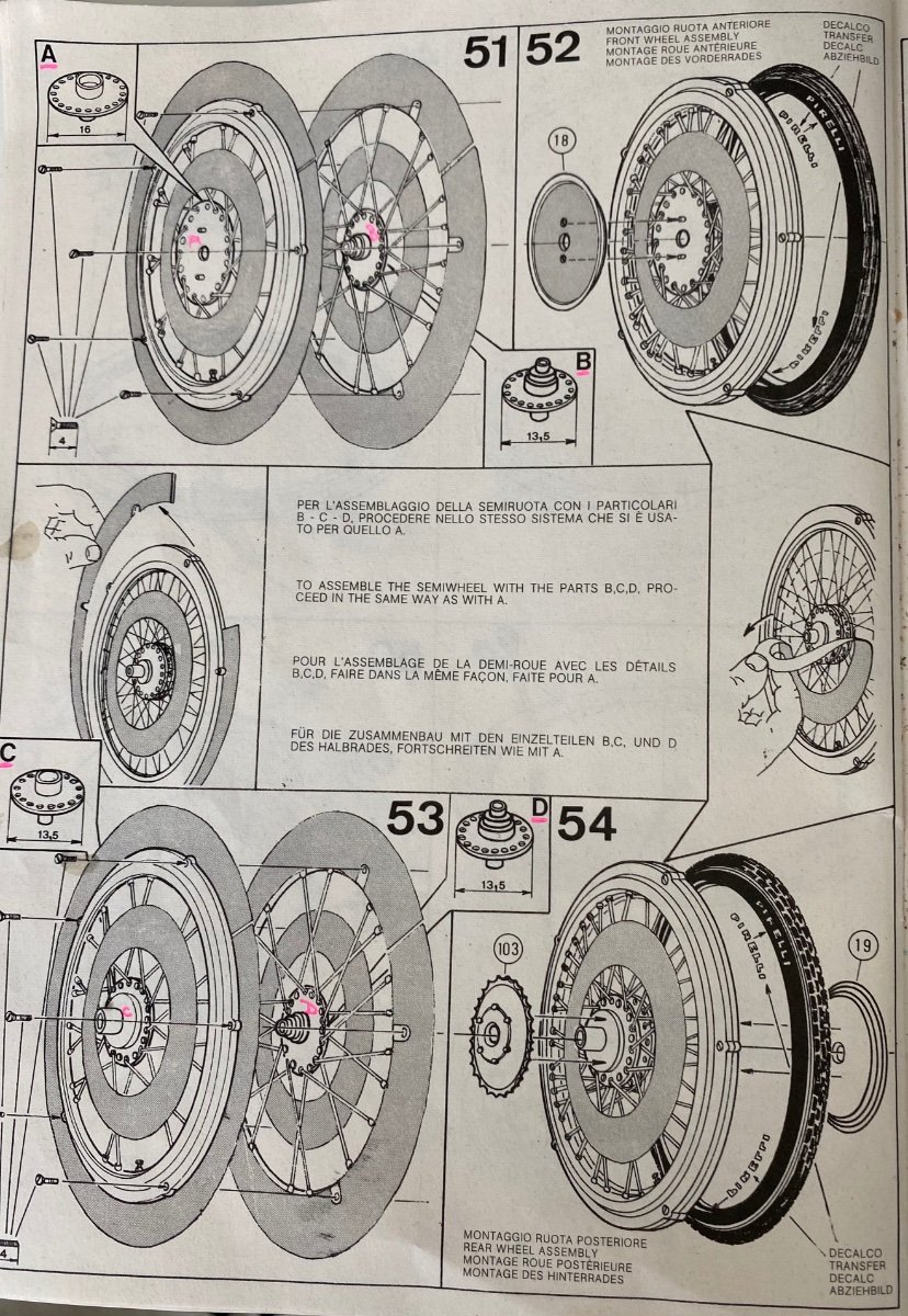
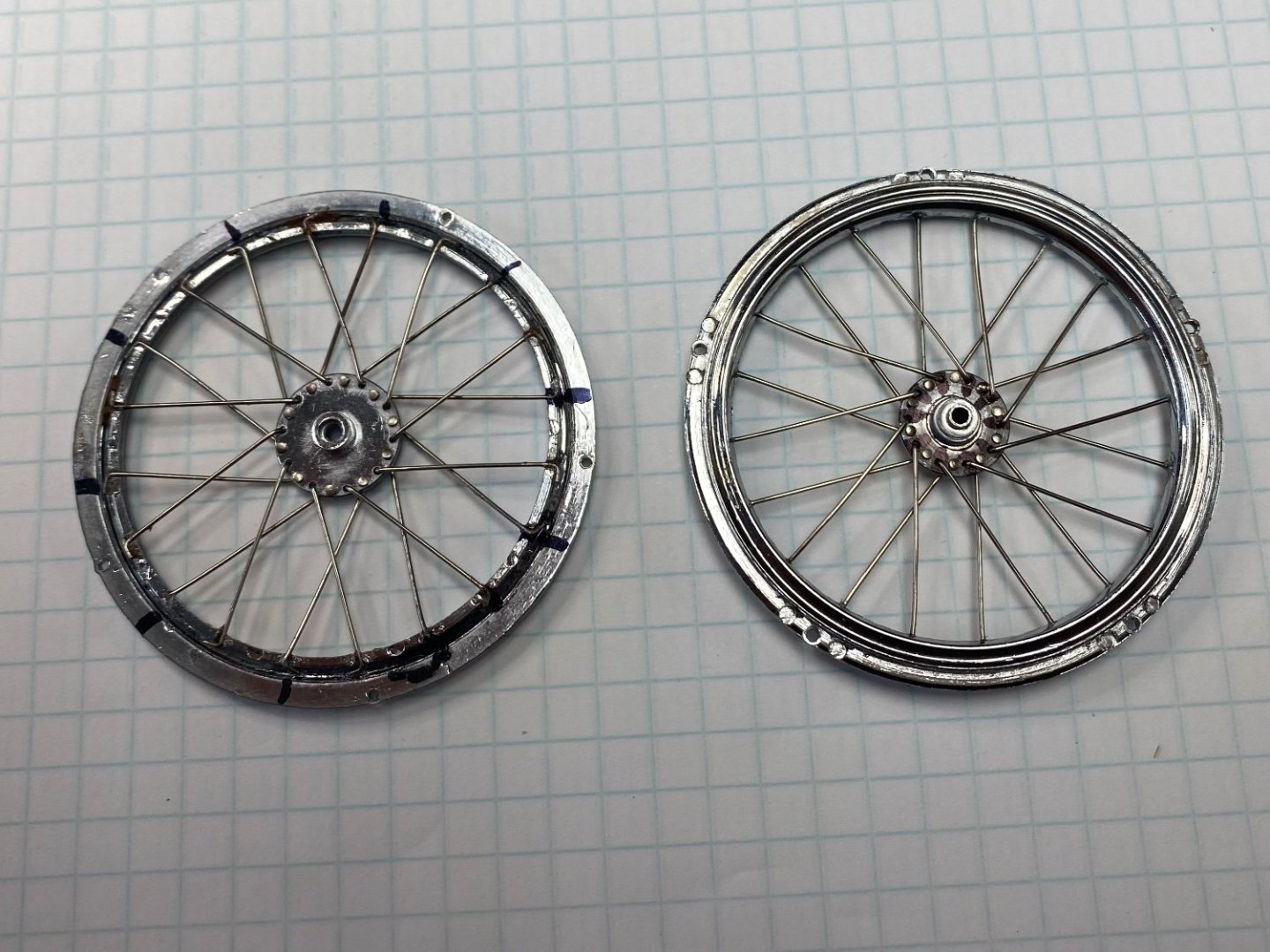
Nothing better that hear from experts. When I was assembling the two halves of the spoked rims I looked for any markings that would have been included tor the correct assembly. I didn't see any, so I proceeded to eyeballing the setup. If I was making this model for sale or museums, I would unmount the wheels, unscrew the rims (5 mini screws) and rotate the rim one hole. But, I am going to let this go as is. If you look closely at the overall assembly you will find a bunch of "oops". Building this model has been frustrating, tedious and incredible difficult considering my shaking fingers, bad sight and lack of five hands. But I have loved every minute of it and enjoyed sharing my experiences with the forum.
- 126 replies
-
- 12
-

-

-
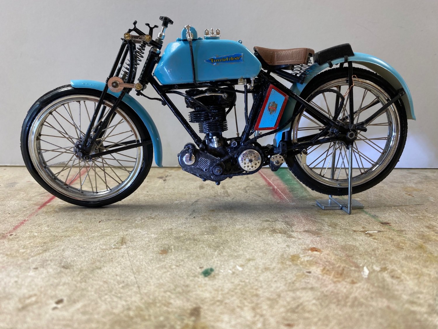
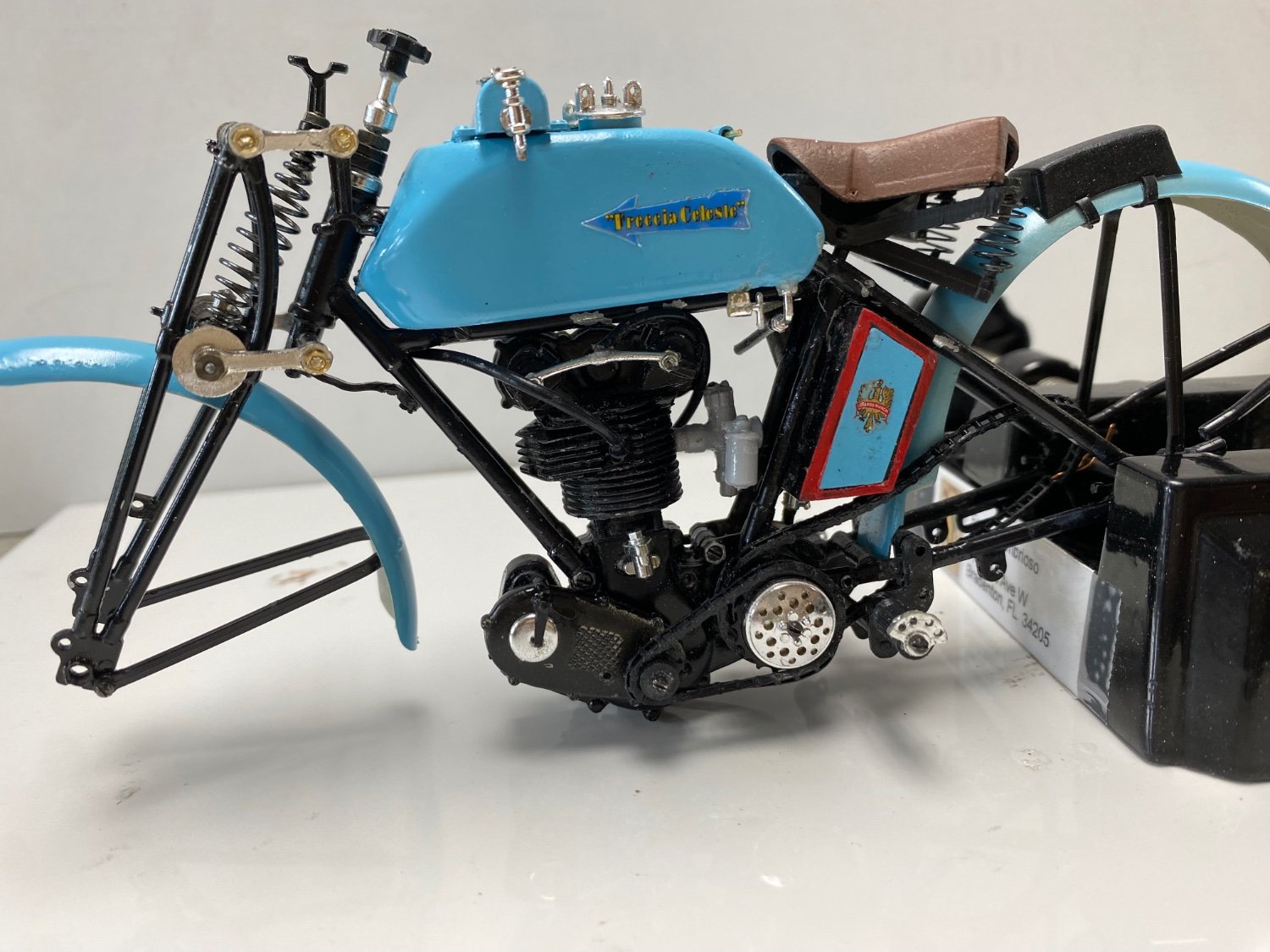
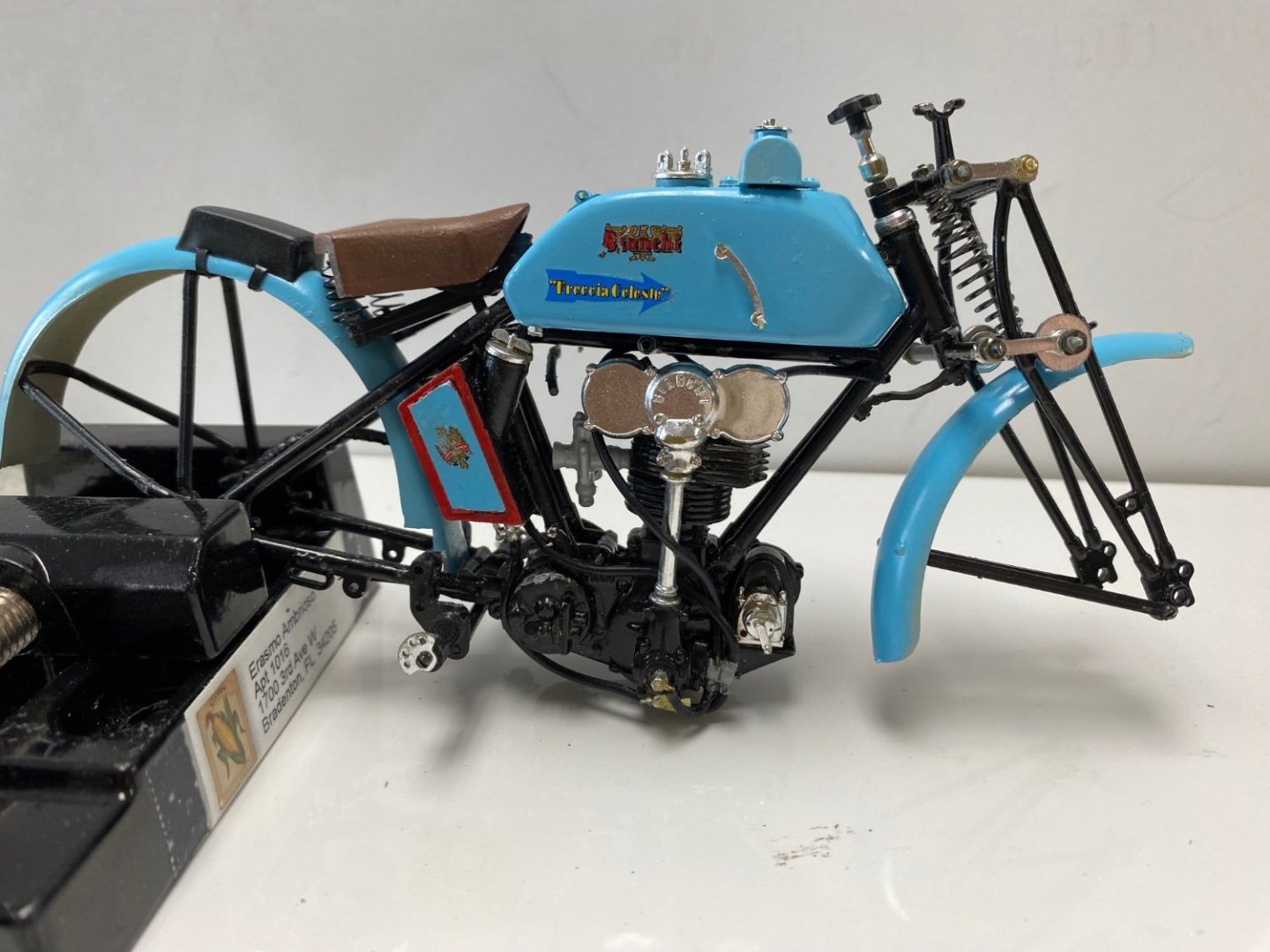
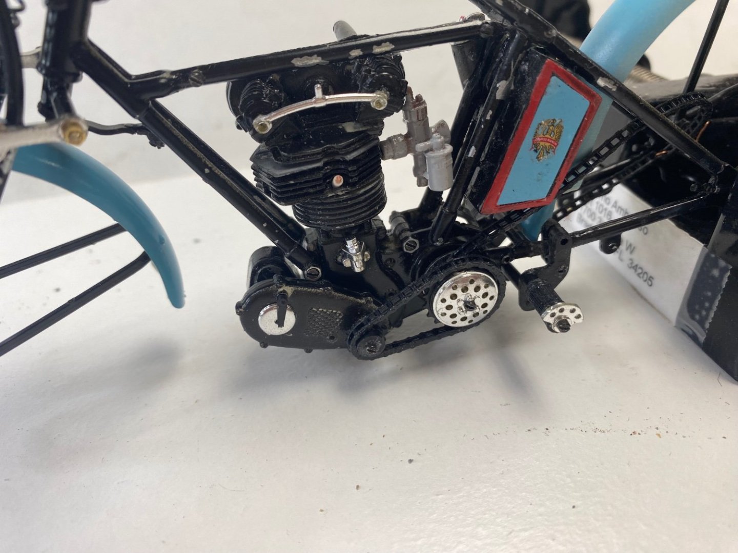
Excellent point Mark. The floor is the top of our well used bench and the wall is a sheet of poster board. But the bike does look real. I wish I haven’t painted the whole engine black because the details are incredible. Thanks for the comments and likes.
-
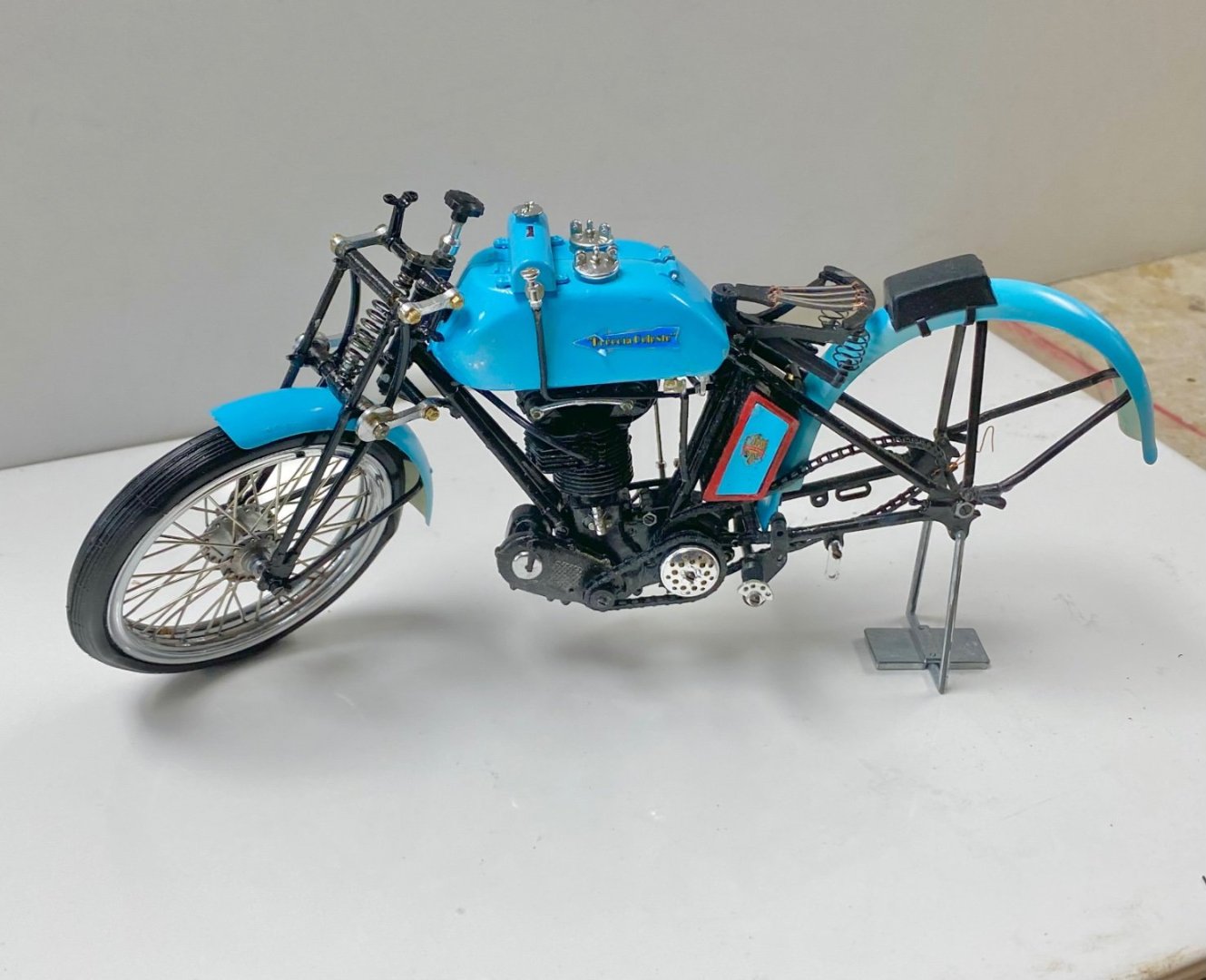
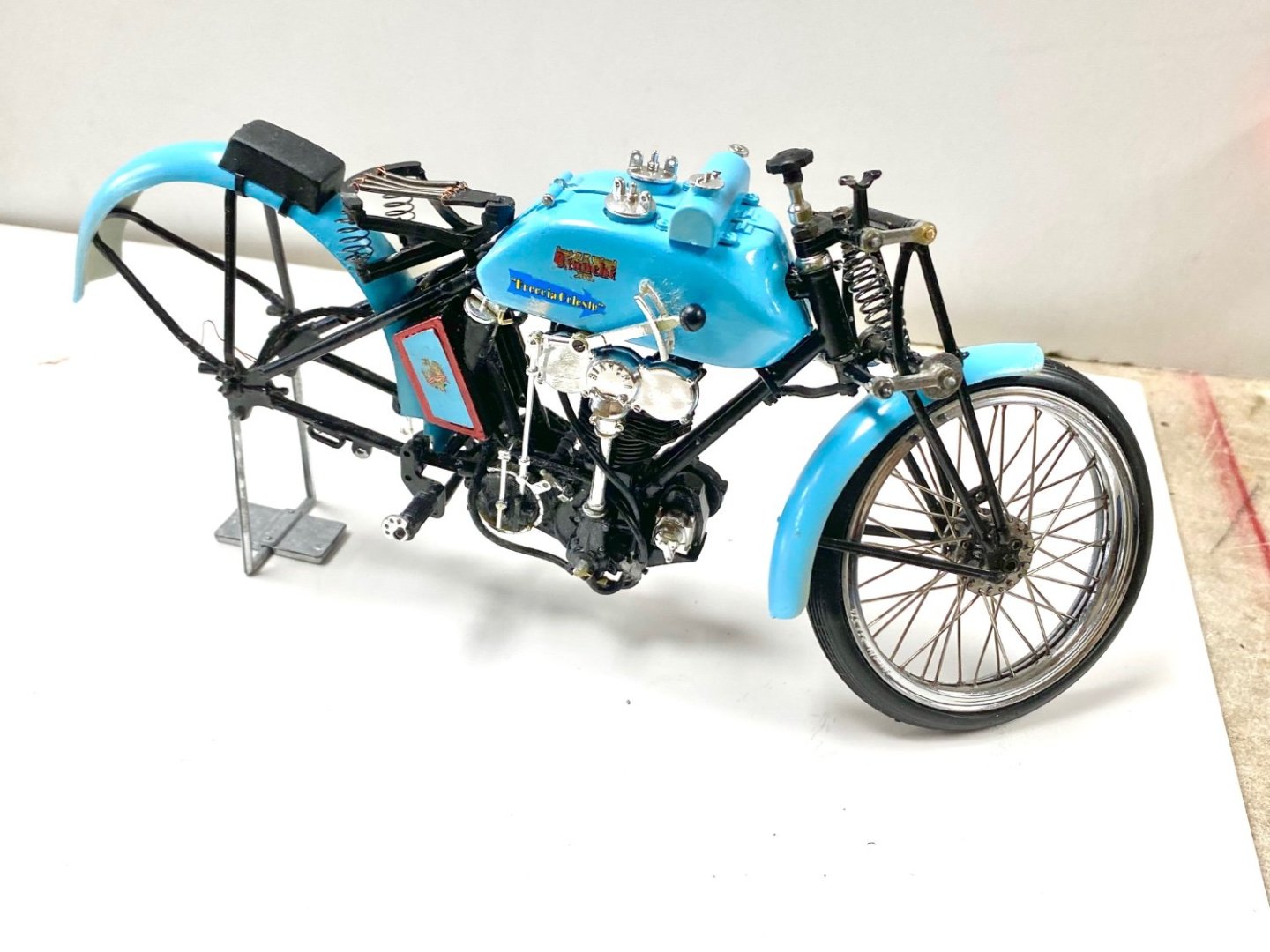
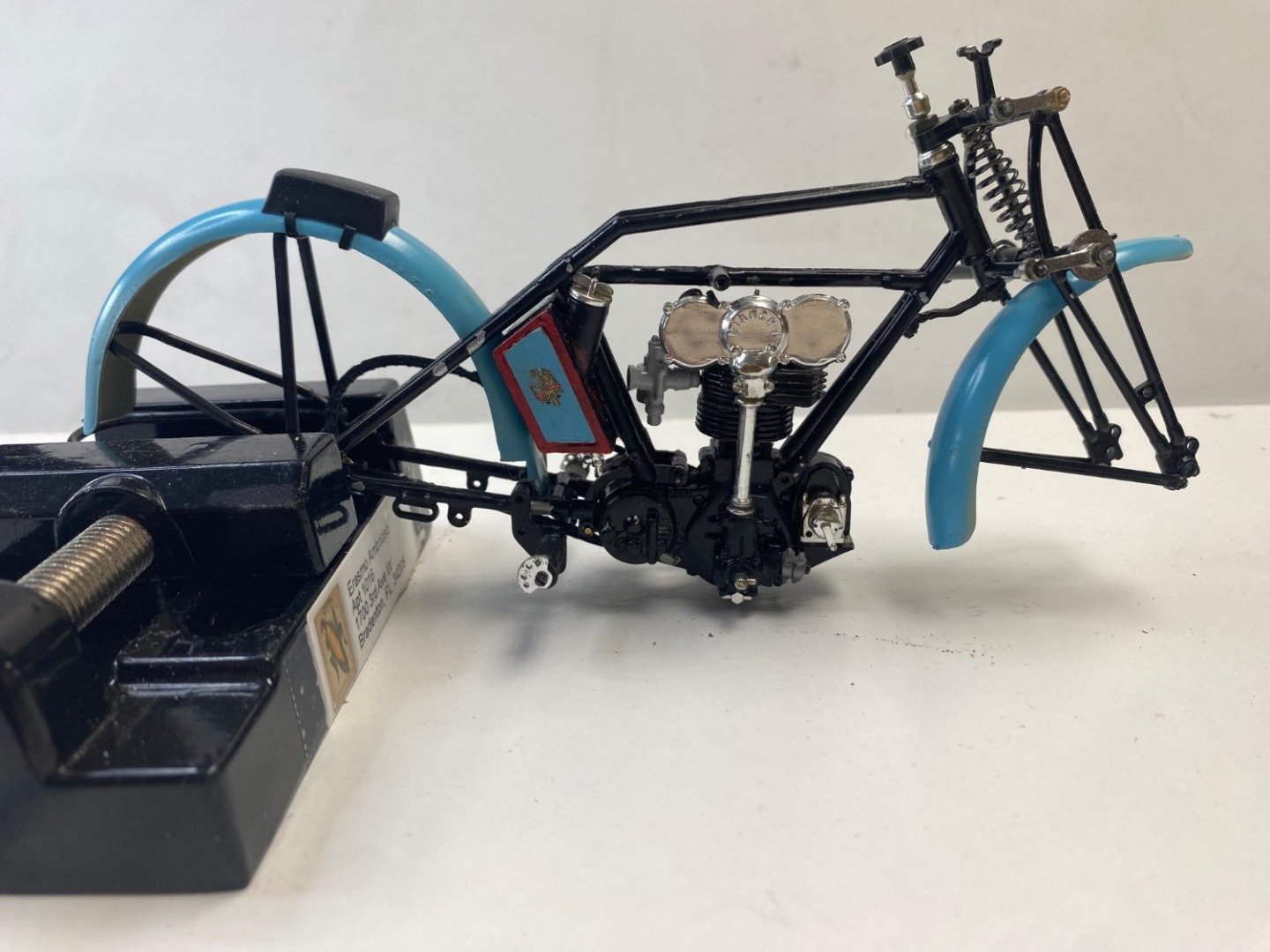
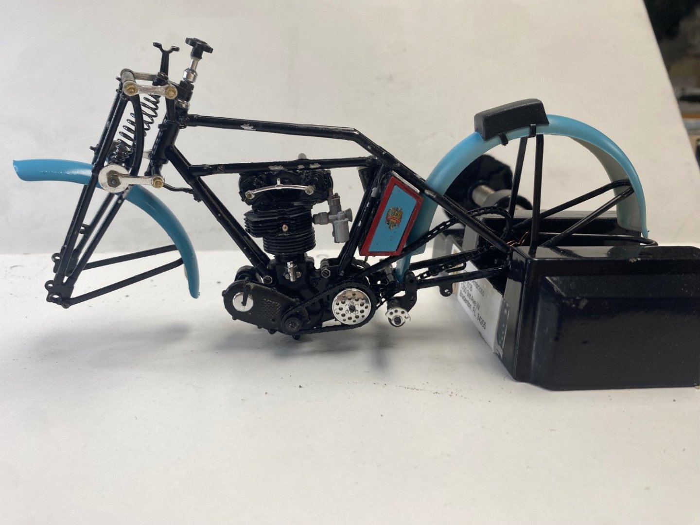
Rear wheel done. It was easier that the front. Experience counts. now I present Freccia Celeste standing on her two wheels (plus the stand, 😉) A few more details (like the handrail, brakes and control cables) and I am done. Beer time 🍻🍻


- 126 replies
-
- 12
-
-

-
Well done. I am facing the same problem with my Bianchi. Mine is elastic but I had to break it to put in place. Now I am going to face splicing it back in the drive. Your bike is looking great.
-
CDW, I feel you pain
-
CDW, all I can say is: same here. Had the same problem with my Bianchi bike. Fortunately the acetone worked and I managed to get the spoke wheel finished. Hang in there; there is a finish to all this effort.
-
Amazing work. I smile when I think of your tolerance of 0.008 mm when mine is about 0.500mm. Its a real pleasure to look at your work.
-
Wishing you well.🙂
-
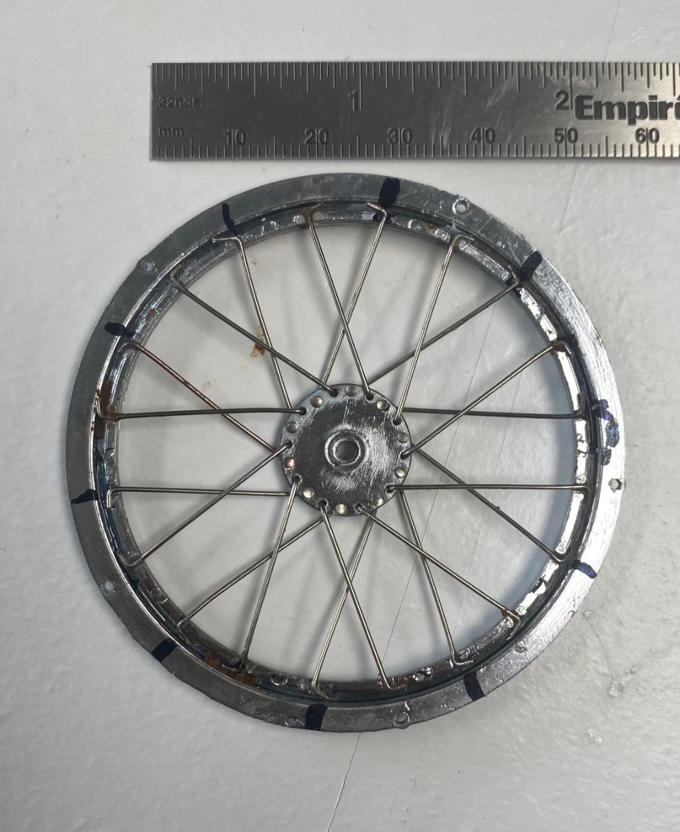
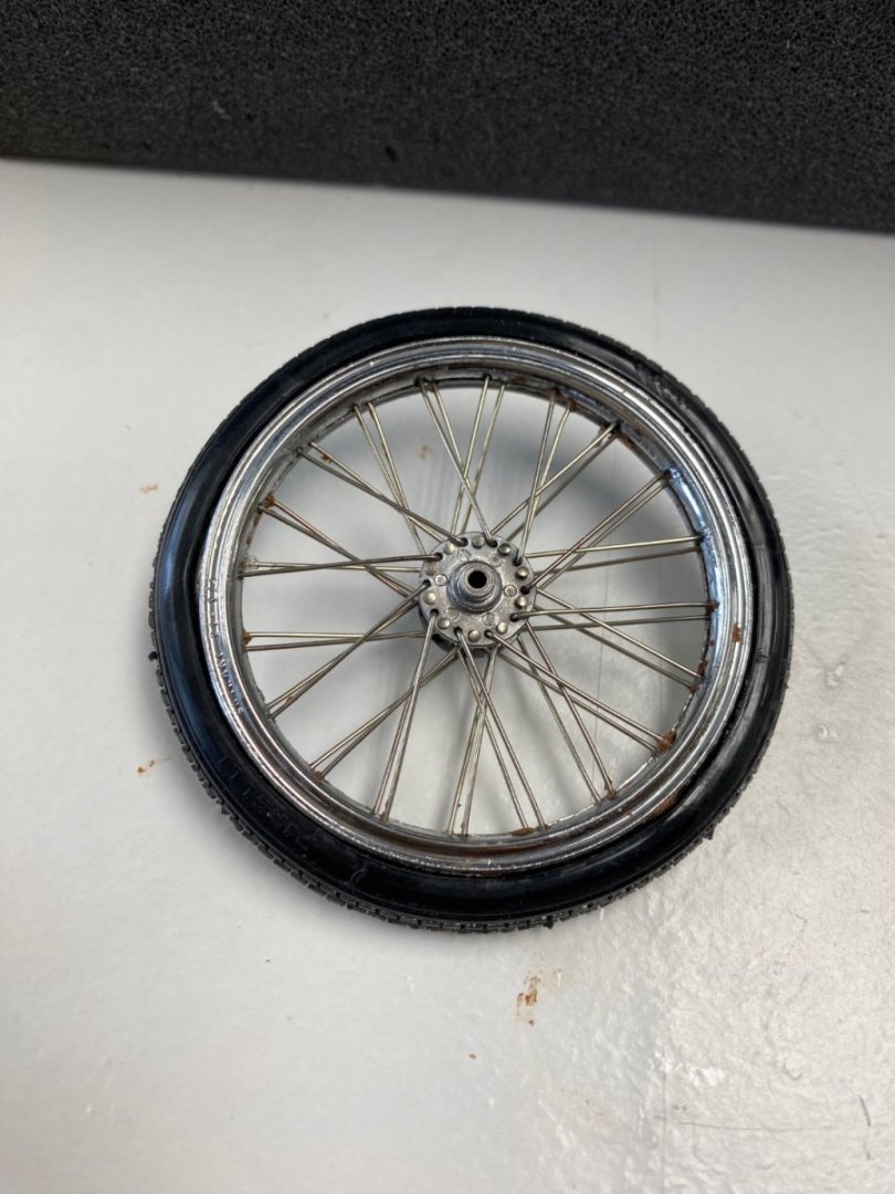
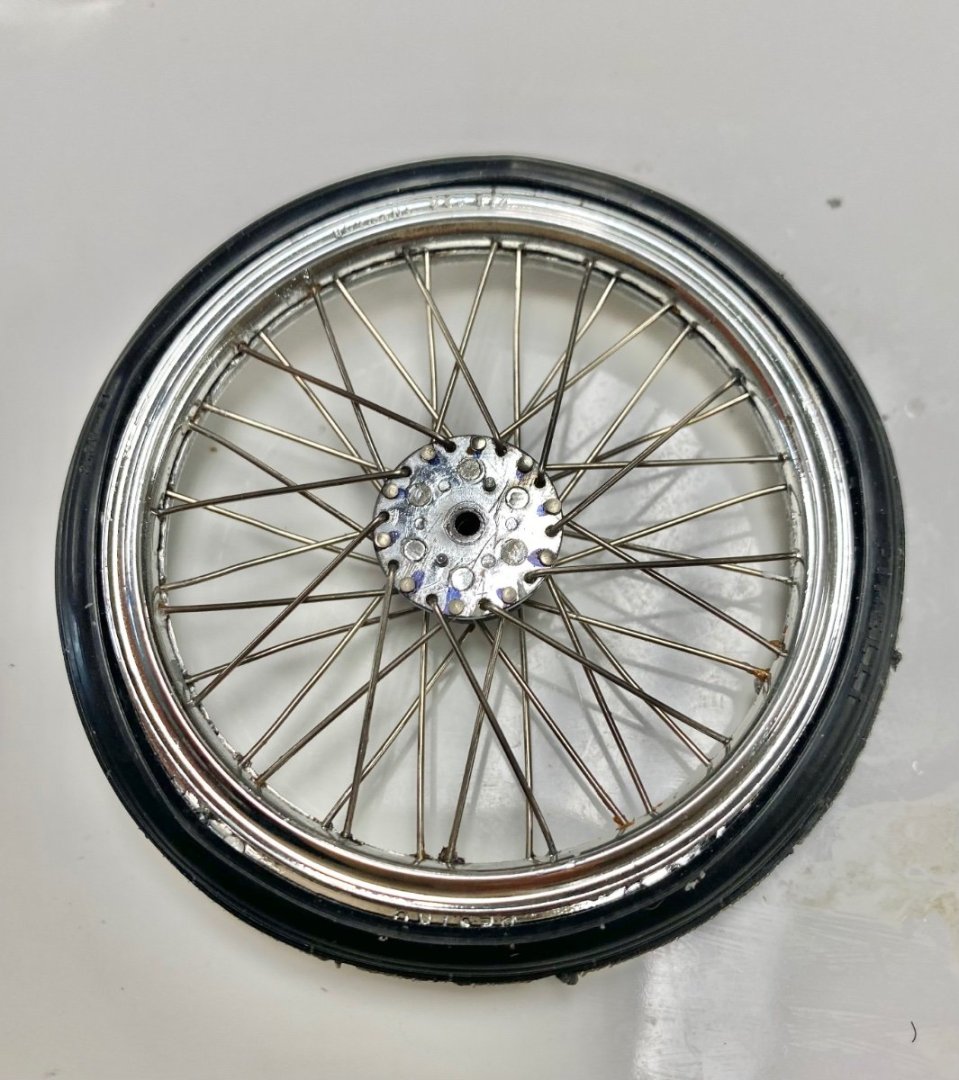
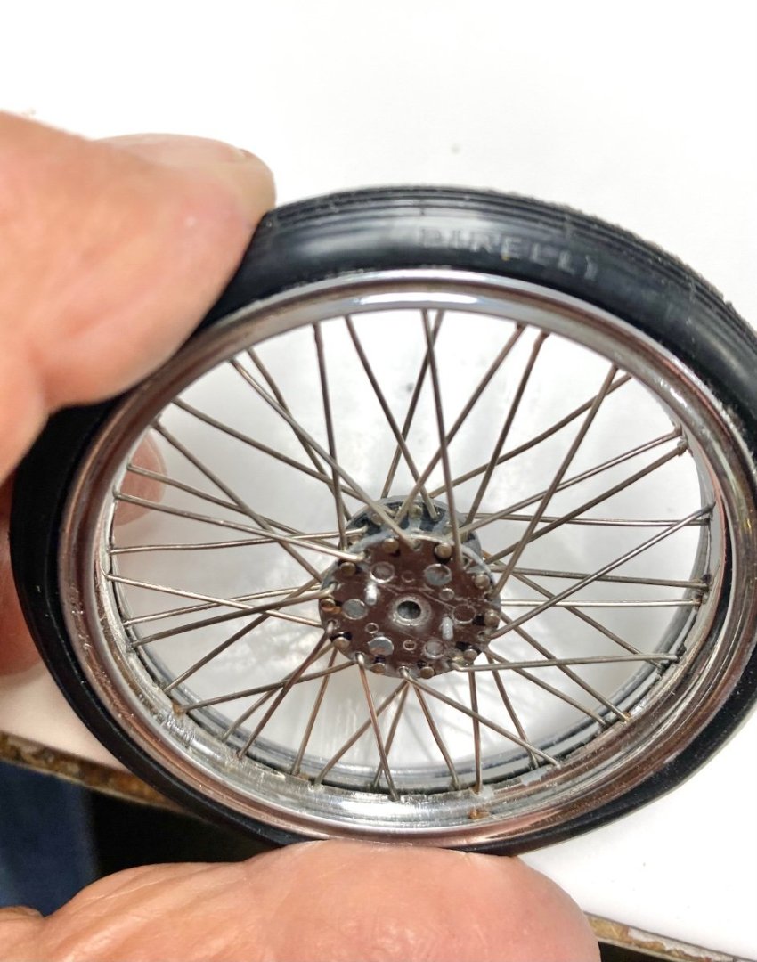
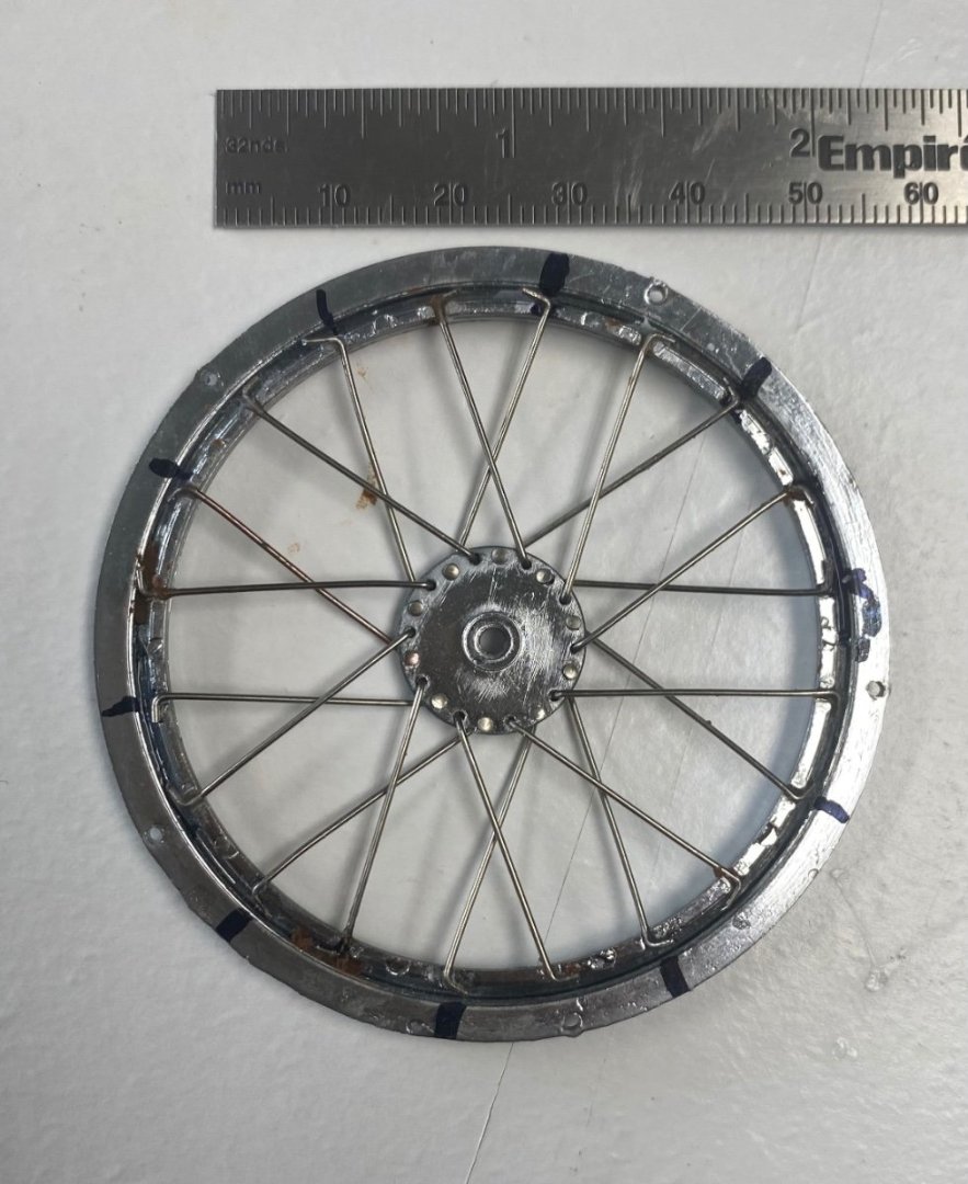
Finally, after three days of work, (a total of 10 hrs, really), the first wheel is done. To set the tire in the rim I had to recall my experiences as a teenager removing car tires off their rims to fix the flats. Working part time in a garage, the only tool available was a steel bar and a hammer. Here I had to use very small screw driver to open up the tire an let it slip on the edge of the rim. As everything else in this build, a very frustrating experience. But I loved every minute of it. After a wait of over 30 years I, finally get to see this kit nearing its completion. Notice the detail on the tire itself: Pirelli. And this is how the Bianchi looks now.
- 126 replies
-
- 13
-
-
-
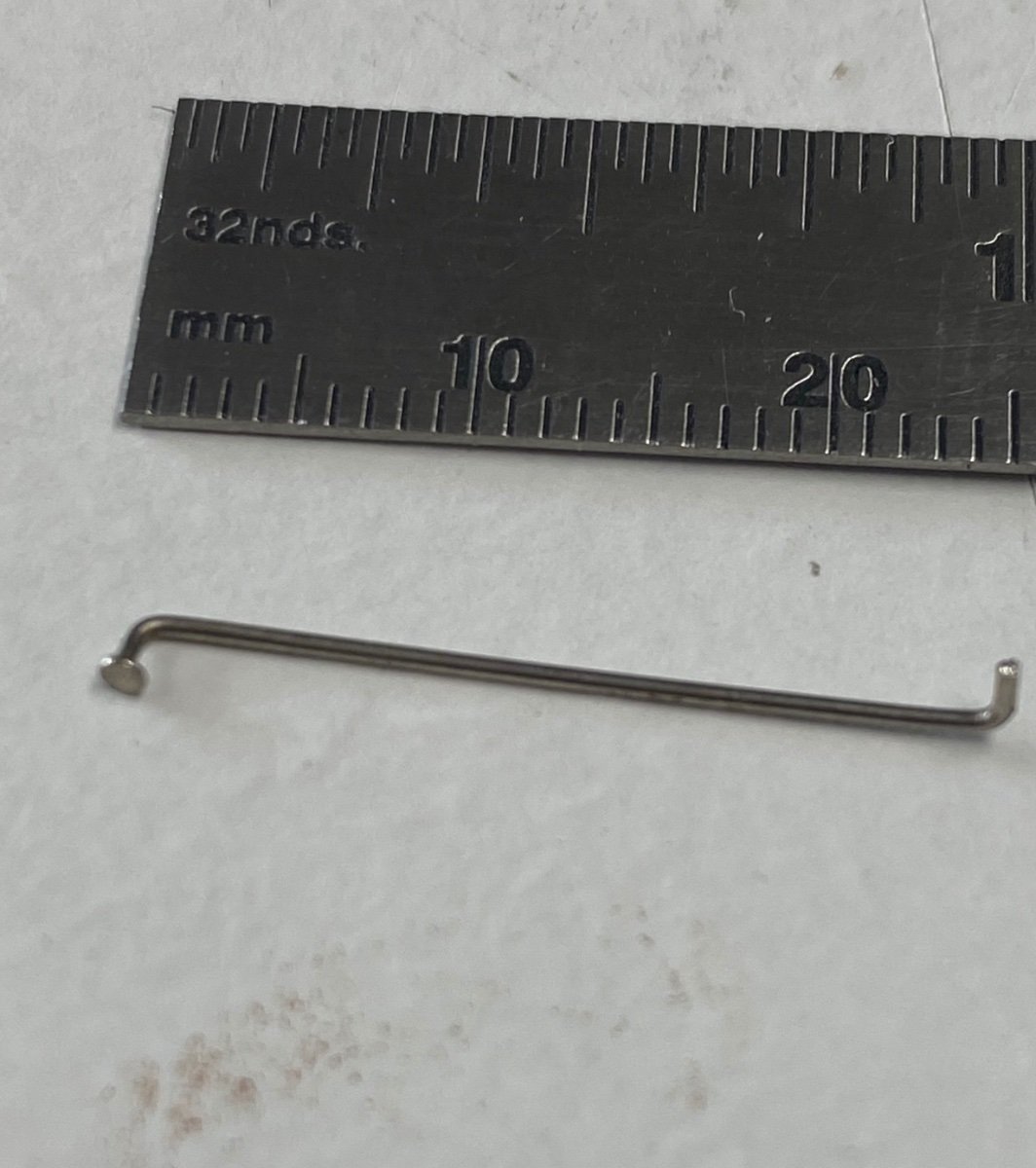
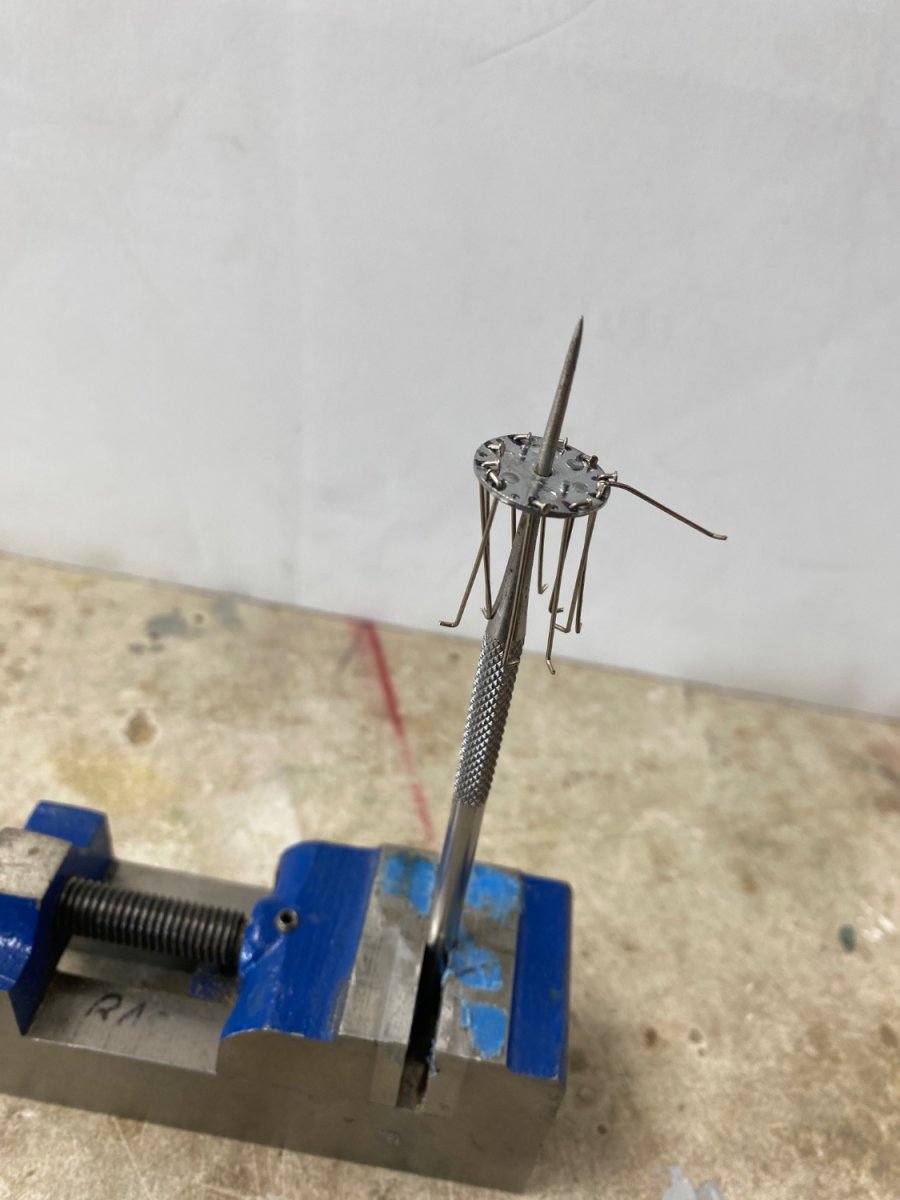
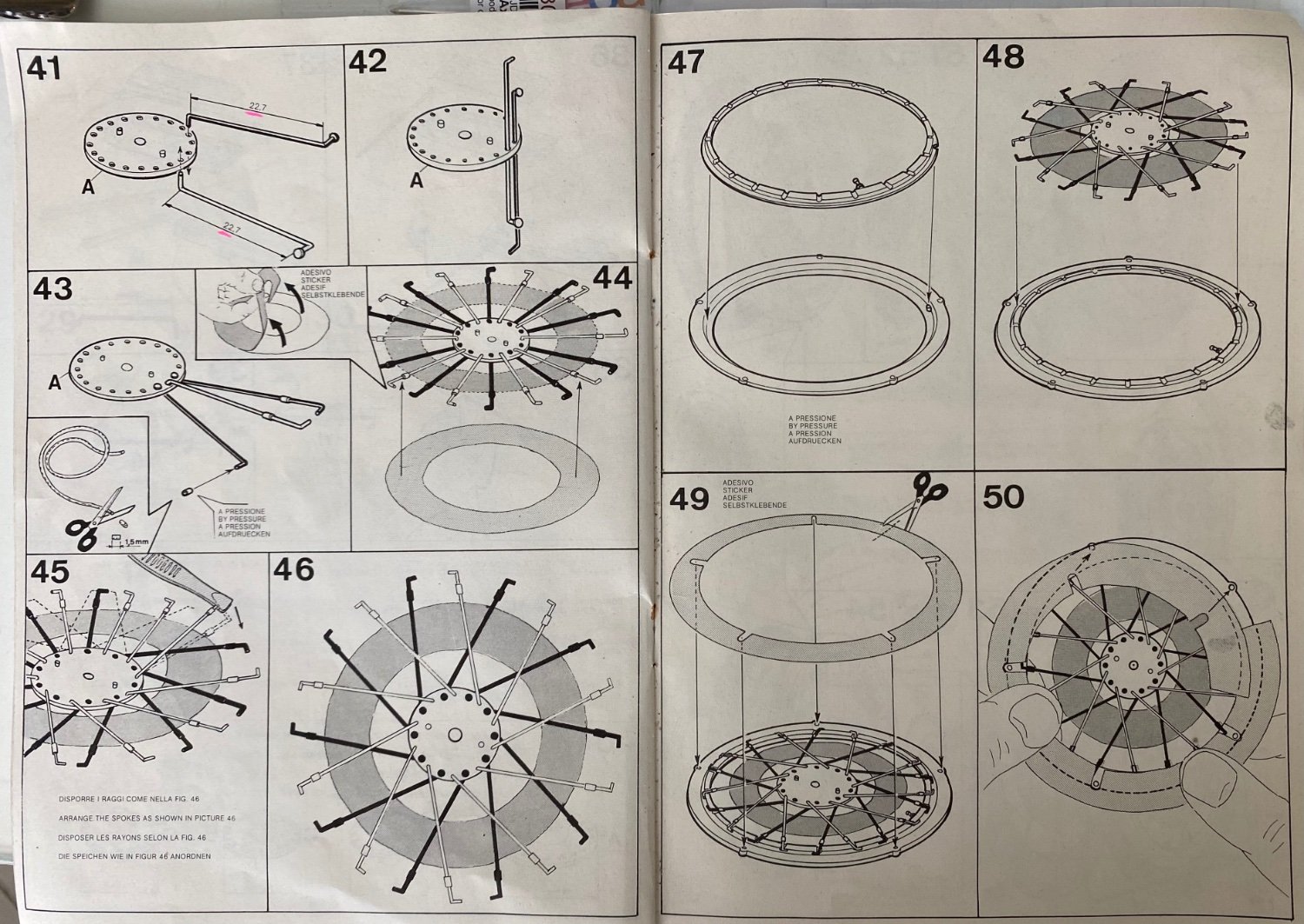
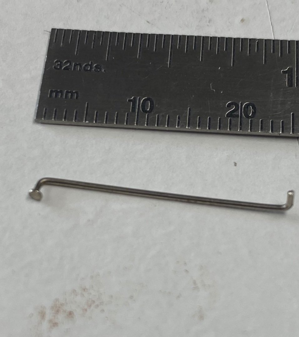
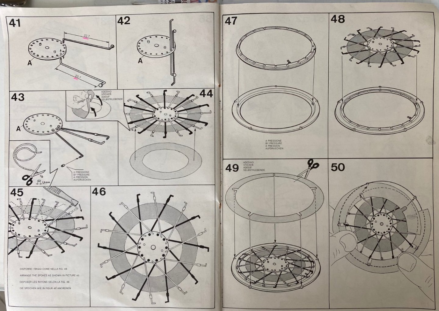
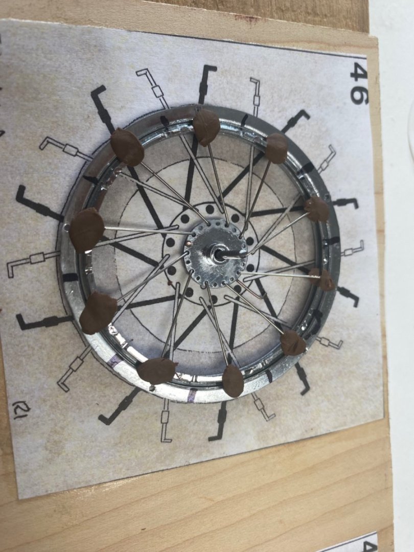
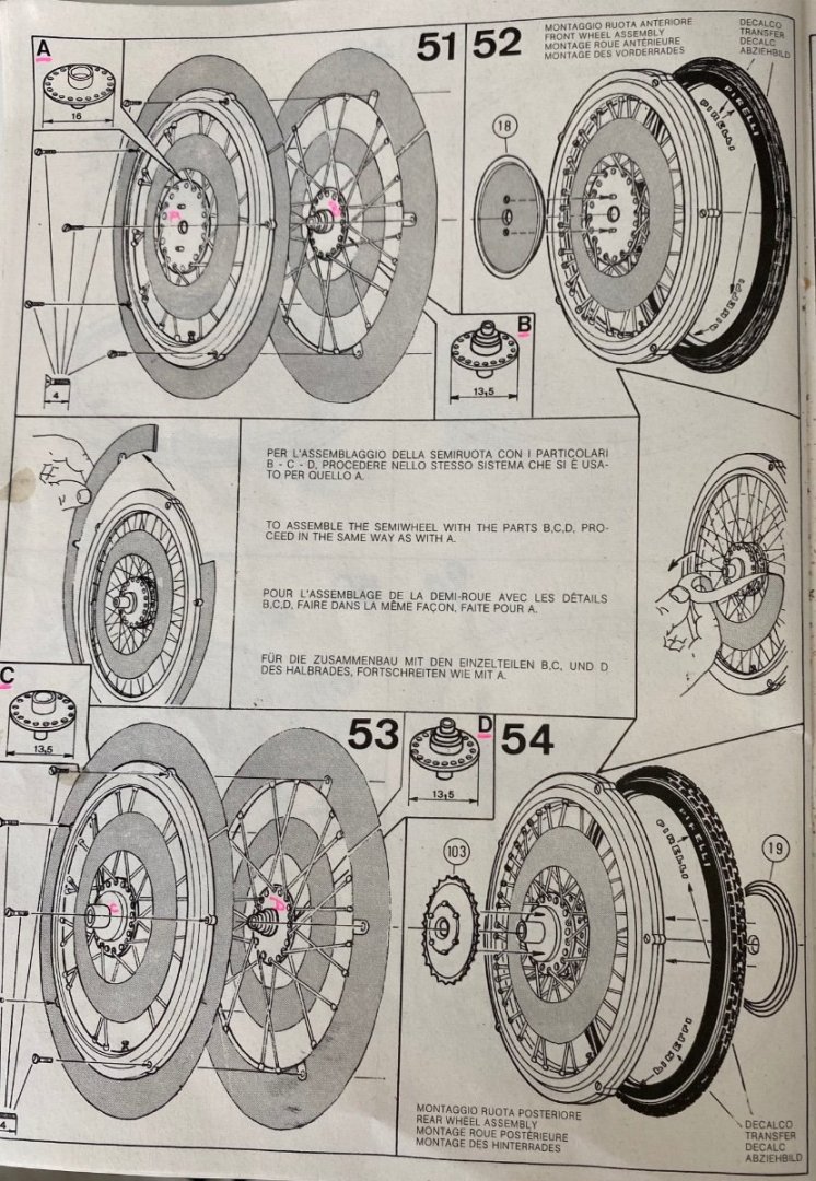
Well, the day came that I had to start assembling the spoke wheels. I have dreaded this moment since I had failed before in my attempts to build this kit back in the 90's. At that time, I started with the wheels and got totally frustrated and abandoned the project. Now, that I am older, I think that have gained some patience and perseverance to deal with failures. I purchased this kit used. It seems that the previous owner had started the wheels and had fabricated the 80 spokes necessary and then quit. So, for the start, I checked the spokes he (or she?) had cut and bend. Horror 🤪, The spokes were bent wrong. So, the first job was to verify the size (two different lengths were required) and the bends. Each wheel has two rims and two hubs to which these spokes are to be inserted. That done, I proceeded, as per the instructions, to thread the spokes into the hubs. This was a little complicated as the spokes are feed alternately on the hub holes: half up and half down. Then another crisis developed. The instructions indicated that the spokes would be lined up as per the diagram and then placed on the corresponding slots in the rims (#47 and #48 below). A tape, with adhesive in one side, was provided to spread and hold the spokes (see #44 and #46 above), but the pattern in #46 is not to scale and therefore useless. I scratched my head several times and decided that I needed something to hold each spoke in its slot (unglued) while I located the others and placed them in the rim. The answer was using modeling clay to hold each spoke in place. Success🙂 And here are the results. And, to make it more interesting, I assembled the second half of the rim's hub backwards. I had to submerge the rim with the spokes in acetone to remove the CA glue. But there is a happy ending to the story. The challenge continues........

- 126 replies
-
- 13
-
-
-
Now you got me excited. I will be following you. I thought that my Bianchi was complicated. Your engine is a beauty. Kudos
-
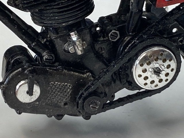
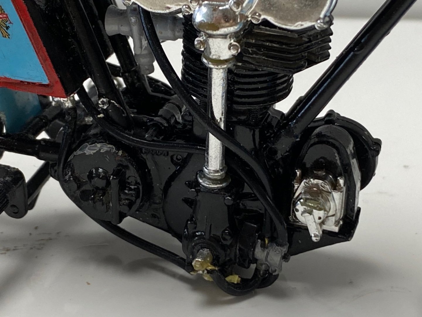
Did the negative wash of light over dark and following are the comparisons. Before: And after I used Vallejo grey and silver. The result looks like a dirty engine and the black hole of gloss black is gone. Following is the progress to date: Spoke wheels next.

- 126 replies
-
- 14
-
-
Thanks for the comments and likes. I went to CDW's log of the Buccaneer and got very good tips about washes. BTW, he's done a beautiful job on that aircraft. I am going to paint some plastic with the gloss and try a negative washing of light over dark. I will follow up with my findings.
-
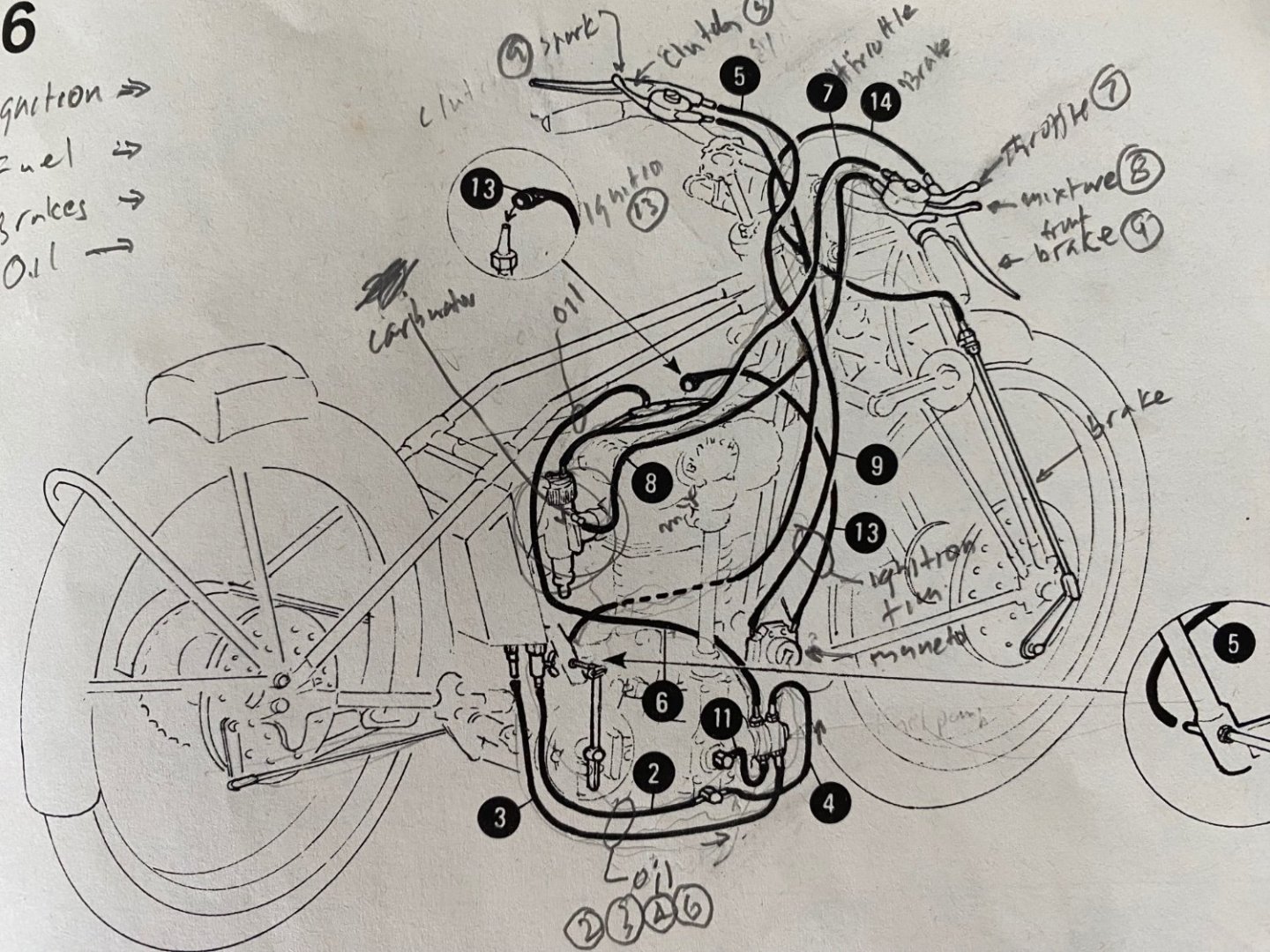
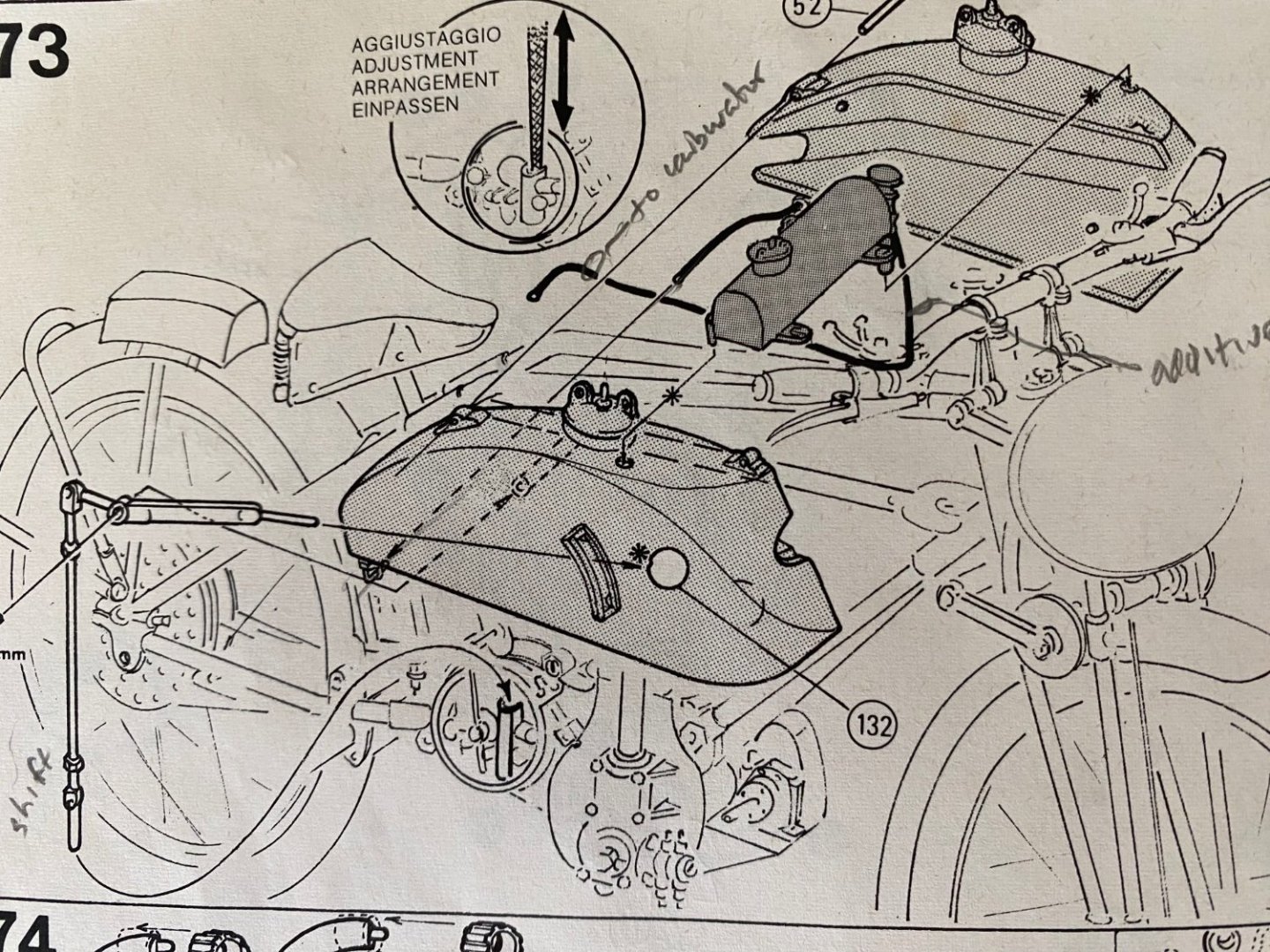
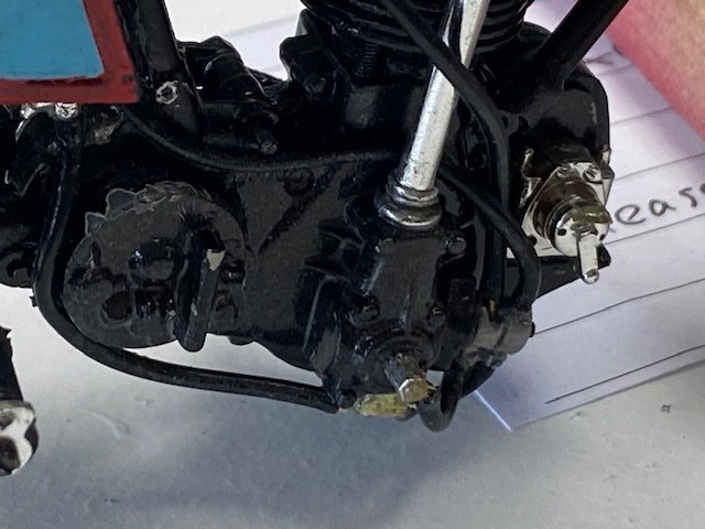
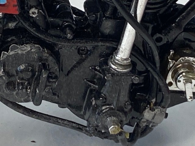
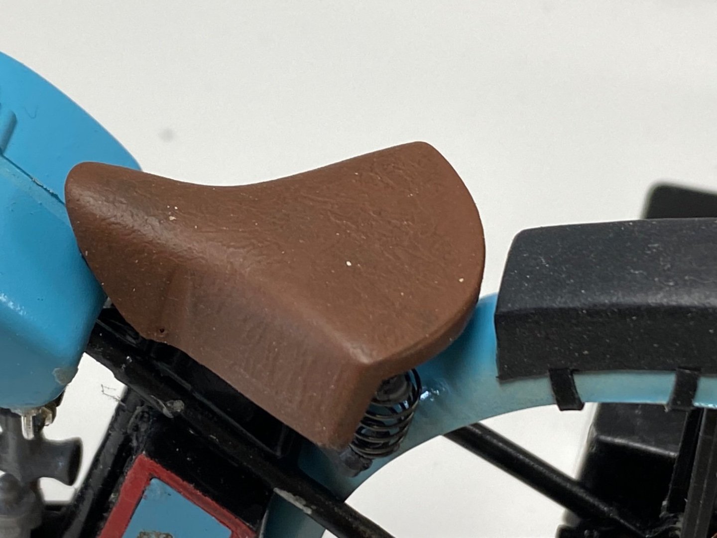
A little more progress as I tackle the piping and wiring. The mystery of the little tank on top of the fuel tanks is resolved. The tank is an oil reserve tank and is piped back to the main oil tanks. This tank actually feeds two oil pumps which feed the DOHC and the crankcase. As you can see it is difficult to see the details on the lower part of the engine due to the glossy black paint. I am thinking about using a thin grey wash over it . What do the forum think about it? And finally the seat came out OK. I tested several solvents and found that acetone did the job. Still got a little more of the cabling to do but I think I will build the wheels before I install the handlebars, which are already done. Thanks for following, your advise is very valuable to me.

- 126 replies
-
- 16
-
-
-
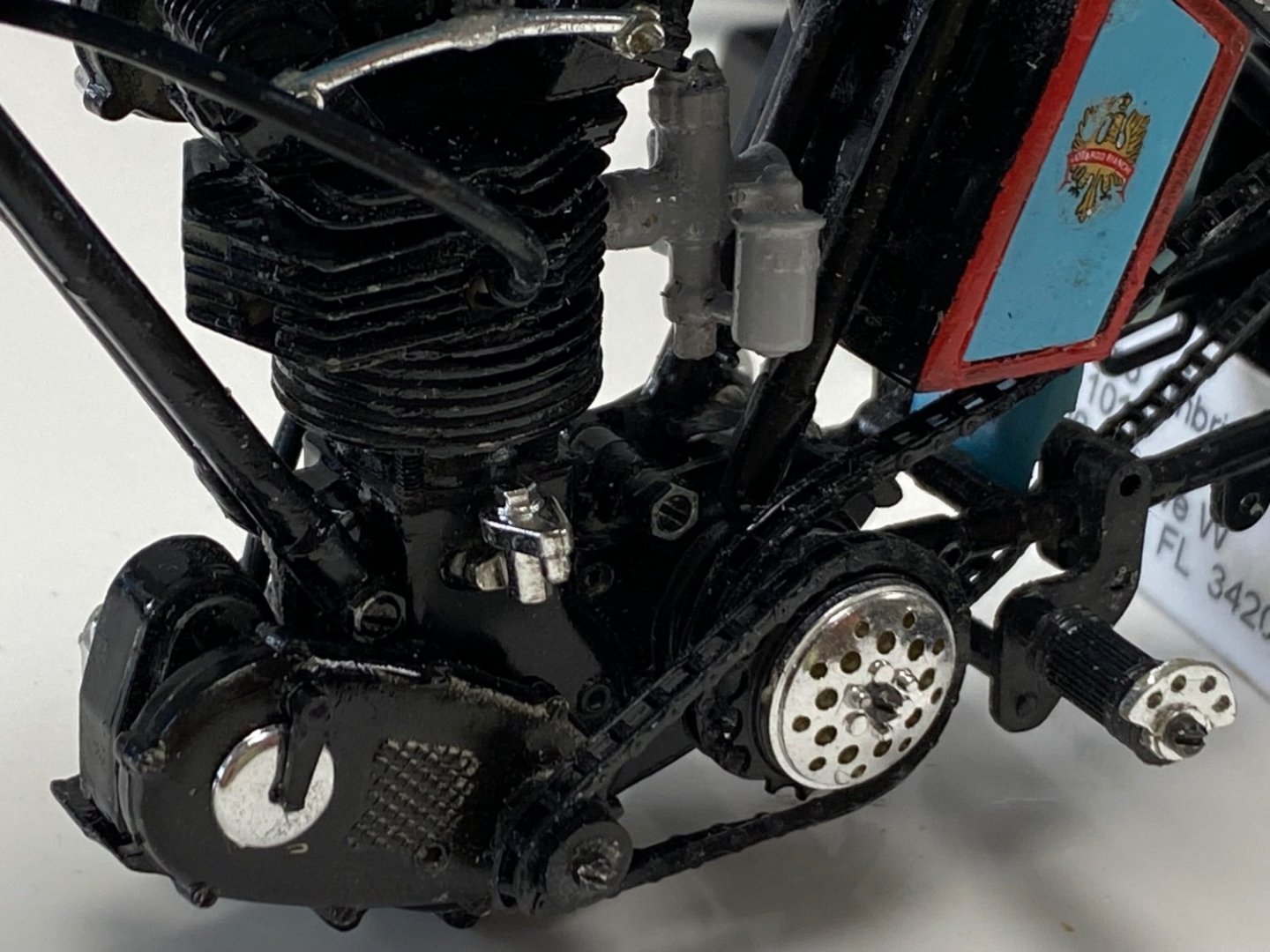
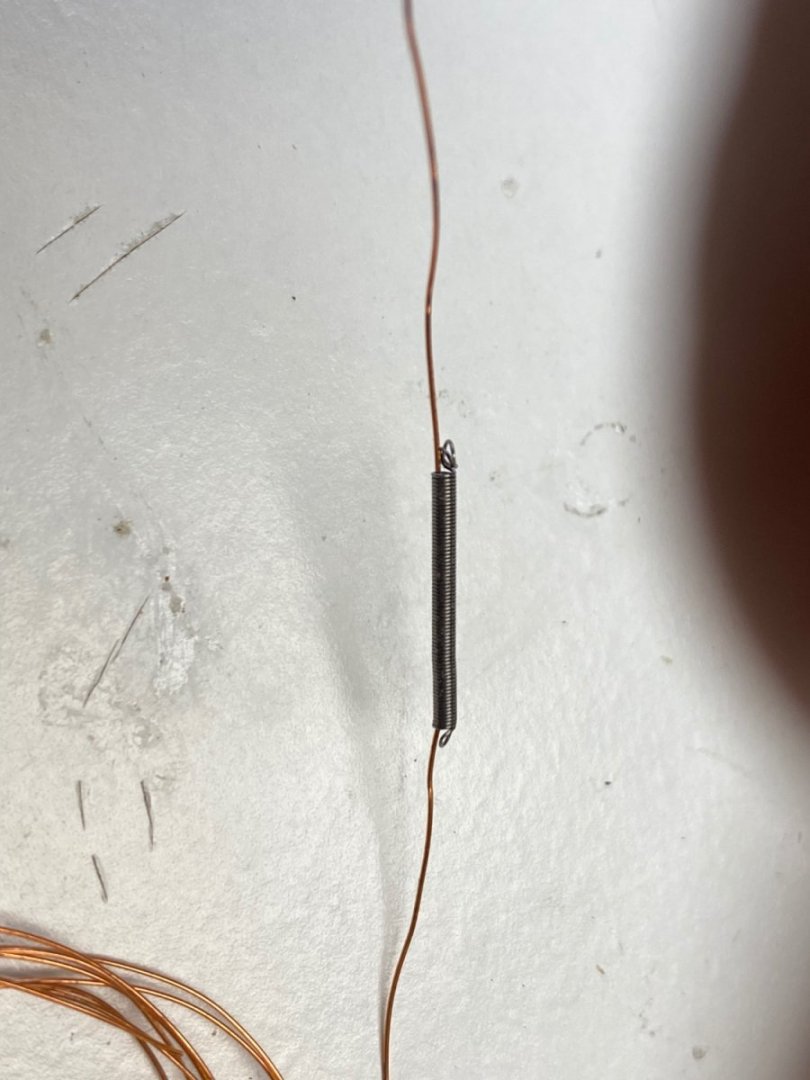
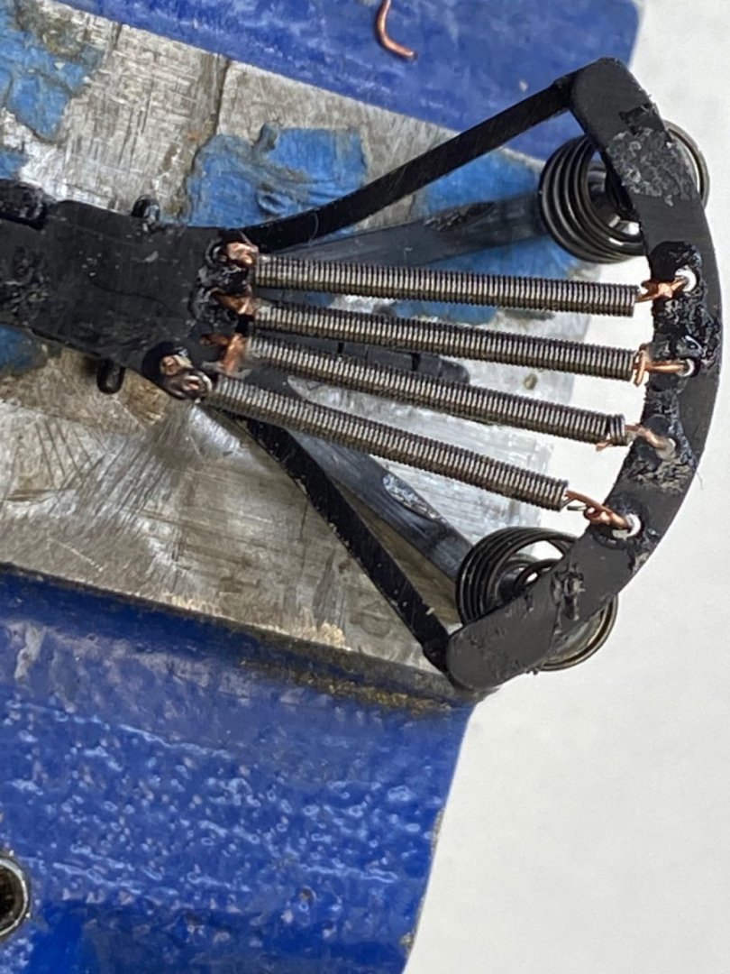
Keith, I followed your recommendation and painted some of the rubber spruces. I also cut pieces of the rubber and used acetone, lacker thinner, and mineral spirits. The paint got sticky but the rubber was not affected by any of the solvents. Then I painted another piece of the rubber with acrylic paint and it stuck and dried solid. So my next step is to try to clean the seat with one of the solvents and paint it with acrylic paint. Hopefully it will work. In the meantime I tackled the seat frame. This one has four really small springs (see post #28) and I had a hell of time trying to open the ends of these springs that are 1.0mm diameter. Finally I figured a way by threading a fine wire through the spring and wrapping the ends in the seat holes. And the final product: Added a few more details to the engine including the main drive chain and the magneto drive. I painted the the whole engine in black but, in retrospect, I should have followed the color scheme in the kit box (grey bottom and black top) to make some of the details more visible. This is an outstanding kit. Next challenge is fabricating the spoke wheels and installing the handlebars and the seat. Then complete this project with the the piping and cabling of the engine.
- 126 replies
-
- 14
-
-
-
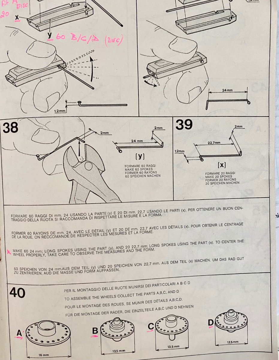
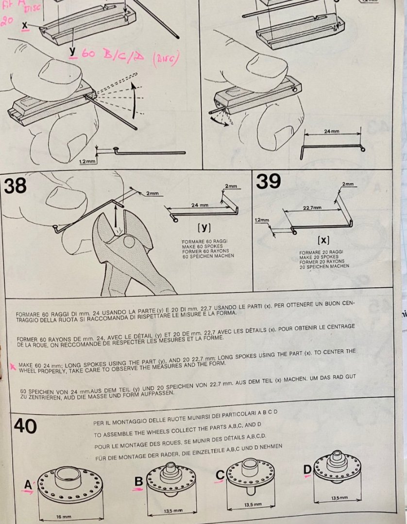
The spokes are the real challenge, they have to be fabricated. I did these on the the first kit back in the 90's. Took me a long time and I lost interest in the model. This time, I have left the wheels for last and I am determined to finish this project. Following are the instructions for the fabrication of the wheels. On the good side is that previous kit owner had already fabricated the 80 spokes and hopefully he did a fair job on them. I am still trying to understand the sequence of assembly using the sticky templates. I have looked at many spoke wheel fabrications on Pinterest but most of them had different rims and also used monofilament line for the spokes. Its going to be fun🤔🤔 For the saga of the leather seat I want to show you how good the paint looks in the rubber seat. Unfortunately is very sticky. Thanks for watching.

-
Guys, thanks to all for the suggestions. I should have checked the effect of the paint on the rubber. First I will try superclean as the Admiral had a supply. Then I may go for the leather but for that I still have to find a glue that wont react to the rubber. Thanks again
-
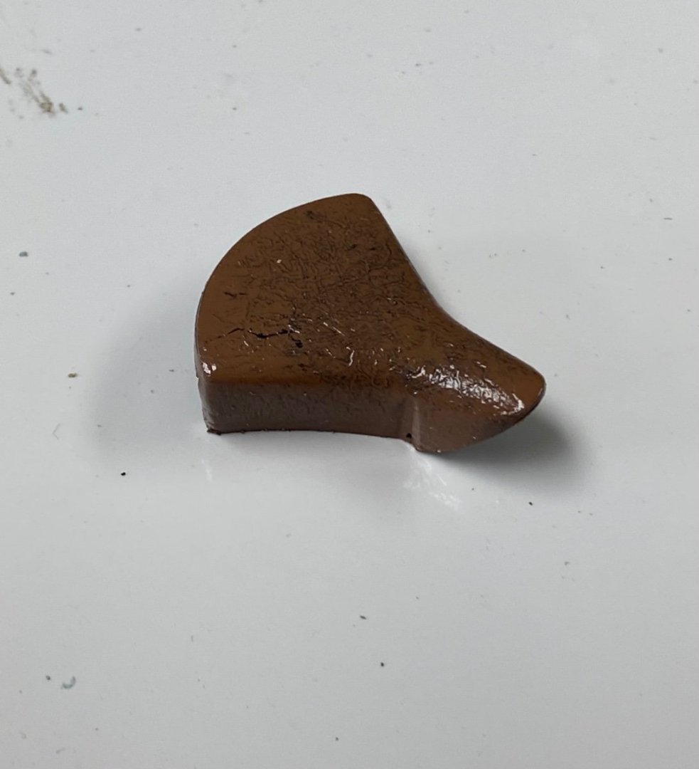
Guys , I need you help again. The seat for this bike is a rubber like material and it has the surface molded to imitate leather. Looking at Kim's (refer to Post #44) I figured that a brown leather color really looked good and proceeded to spray the seat with brown (rattle can) paint. Horror 🤯 (again). Its been three days since the spray and the paint has not dried yet. My thought now is to use paint thinner and try to remove the leather color and live with the original black color. Do you have any ideas about the use of paint over rubber?
-
I love this🤩🤩 Photos are coming
-
Thanks Mark for the revision. Ciao
-
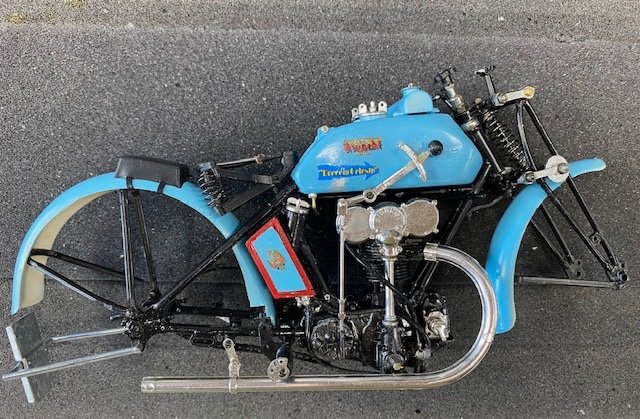
And, by the way, I knew the bike's name was Freccia, with two c's which means Arrow. But when I submitted the post it was edited by the coordinators (??)
-
Holy cow, it seems that I woke up the bees. Very interesting arguments. At the beginning of this thread I said that I thought it was oil to the OHCS and I tend to stick to it and I will ignore the instructions (Oh my!) agreeing with Shipman and Egilman. However the drop oil feed to the chain is coming from the crankcase from a pipe and valve on the left side of the bike. The fact is that, if you look closely at the right side sketch, the oil system is kind of weird. I appreciate you comments and value your opinions and, for that , I thank you all.
-
This what I enjoy this forum. After reading your responses I believe the little tank serves as a reserve tank. The engine is a four stroke and, if you look at the photos below, you will see that the oil pump feeds the OHCS and that the tank feed the carburetor. Thanks a lot for your likes and responses. Like I said before this is a complicated build.