Ras Ambrioso
-
Posts
662 -
Joined
-
Last visited
Content Type
Profiles
Forums
Gallery
Events
Everything posted by Ras Ambrioso
-
 Thanks Valeriy you have been a great inspiration to me.
- 128 replies
-
- 2
-

-
- zulu
- sternwheeler
- (and 1 more)
-
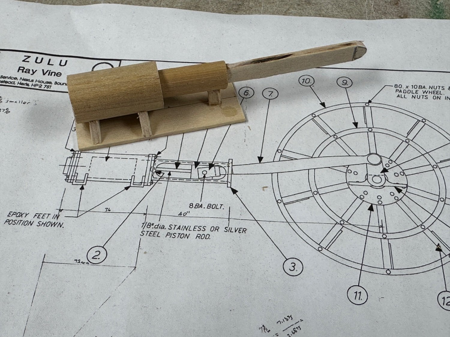
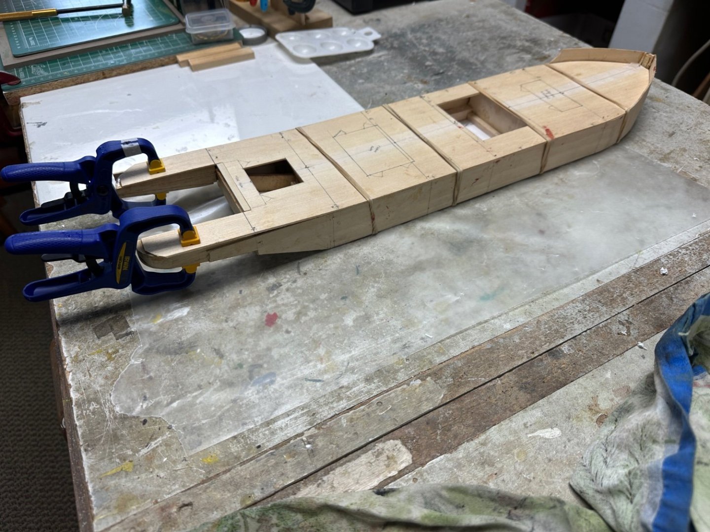
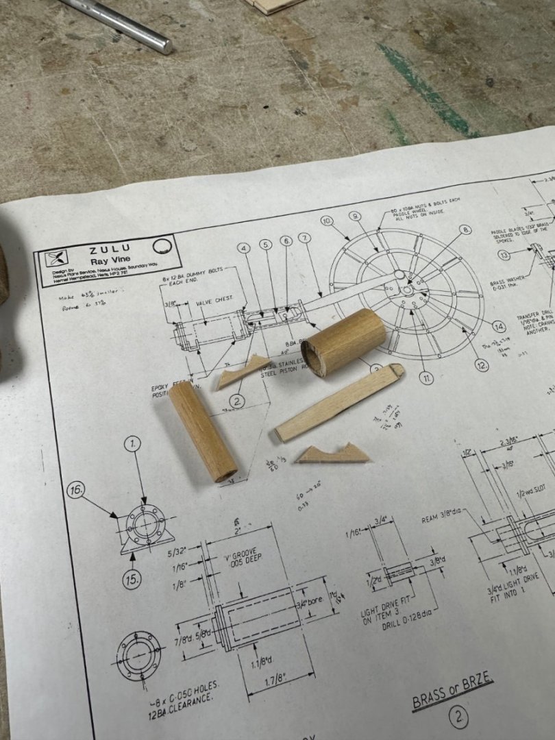
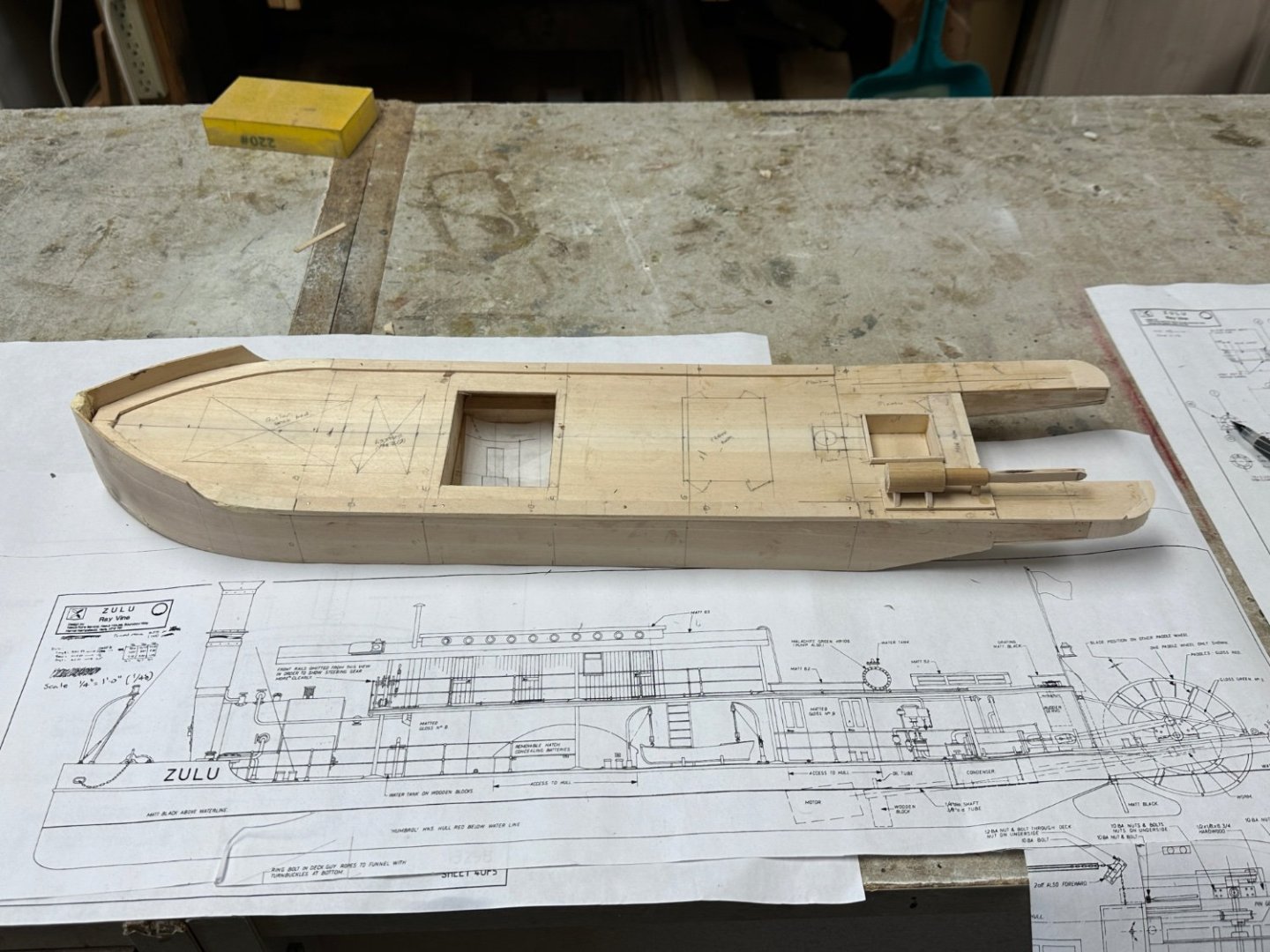
Back to the workbench. Fabricated the sponsons for the paddlewheel out of mahogany, since they will be the support of the paddlewheel axel, and trimmed the sub-deck around them. Sections of the deck will be planked but, the bases for the engines, pumps, boiler and the coamings for the hold hatch, will have to be placed prior to planking. I feel that equipment doesn't look good directly over the wood planks. Thus, I am going to install these items prior to planking. It is amazing to me the amount of ahead planning we must do in these scratch built. So my plan is to basically get all the deck equipment in place before proceeding with superstructures. Started by making a wood mockup the engine. NOTE: the large 1/12 scale drawings was reduced to 1/48 scale. Dimensions shown of the drawings correspond to the larger drawing. I also fabricated the sump for the condensate tank between the engines. After installation of all the coamings and raised bases, I will start the fabrication of the mechanicals in metal, except for the boiler's main body which will be a made from plastic pipe.

- 128 replies
-
- 12
-
-
- zulu
- sternwheeler
- (and 1 more)
-
Amazing, at 1/160 scale is also incredible the amount of realistic detail you have included in this model.
-
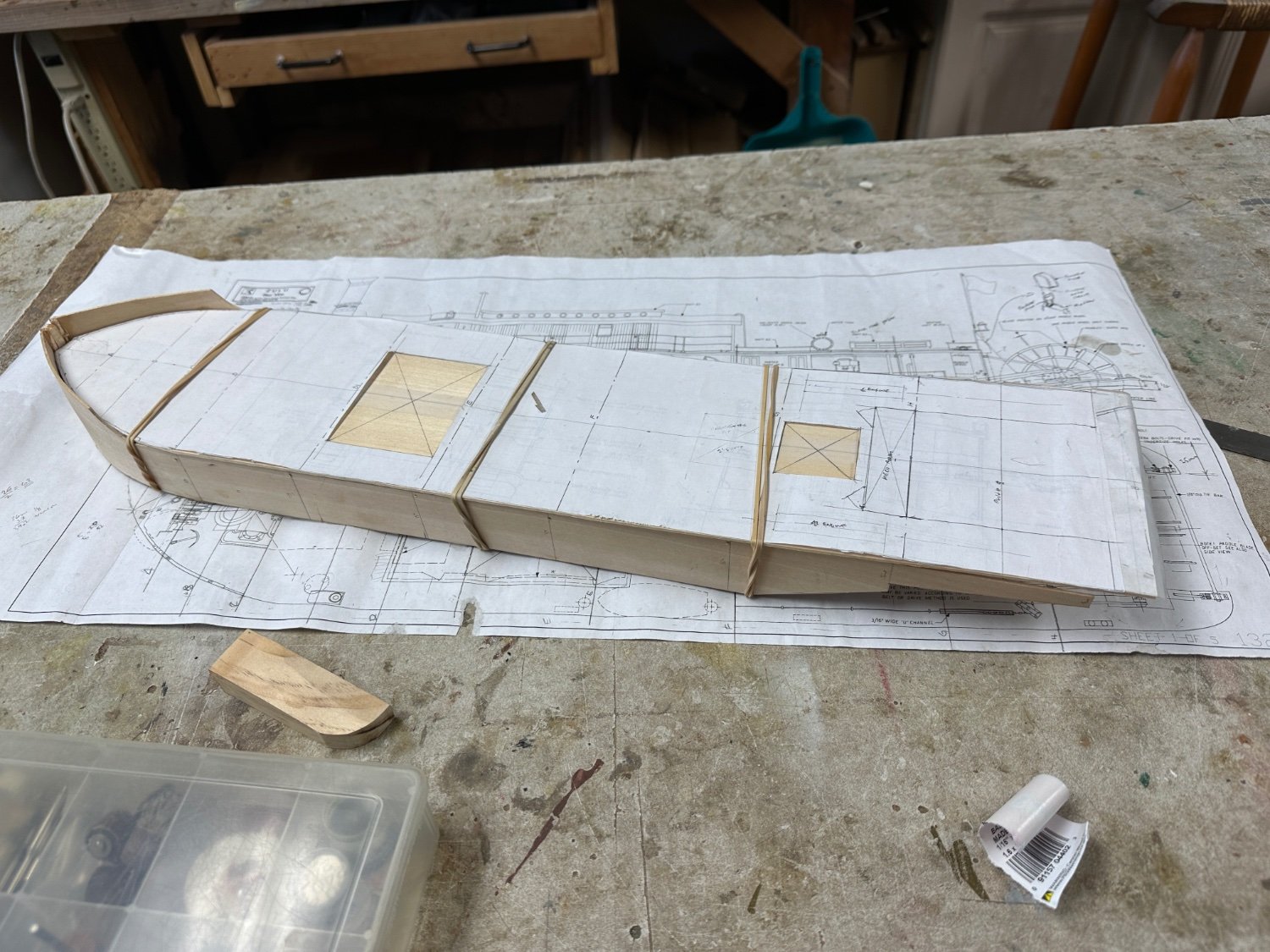
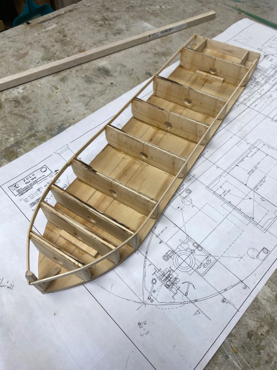
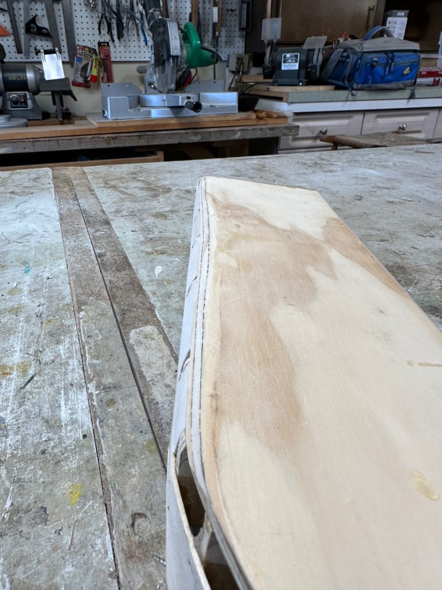
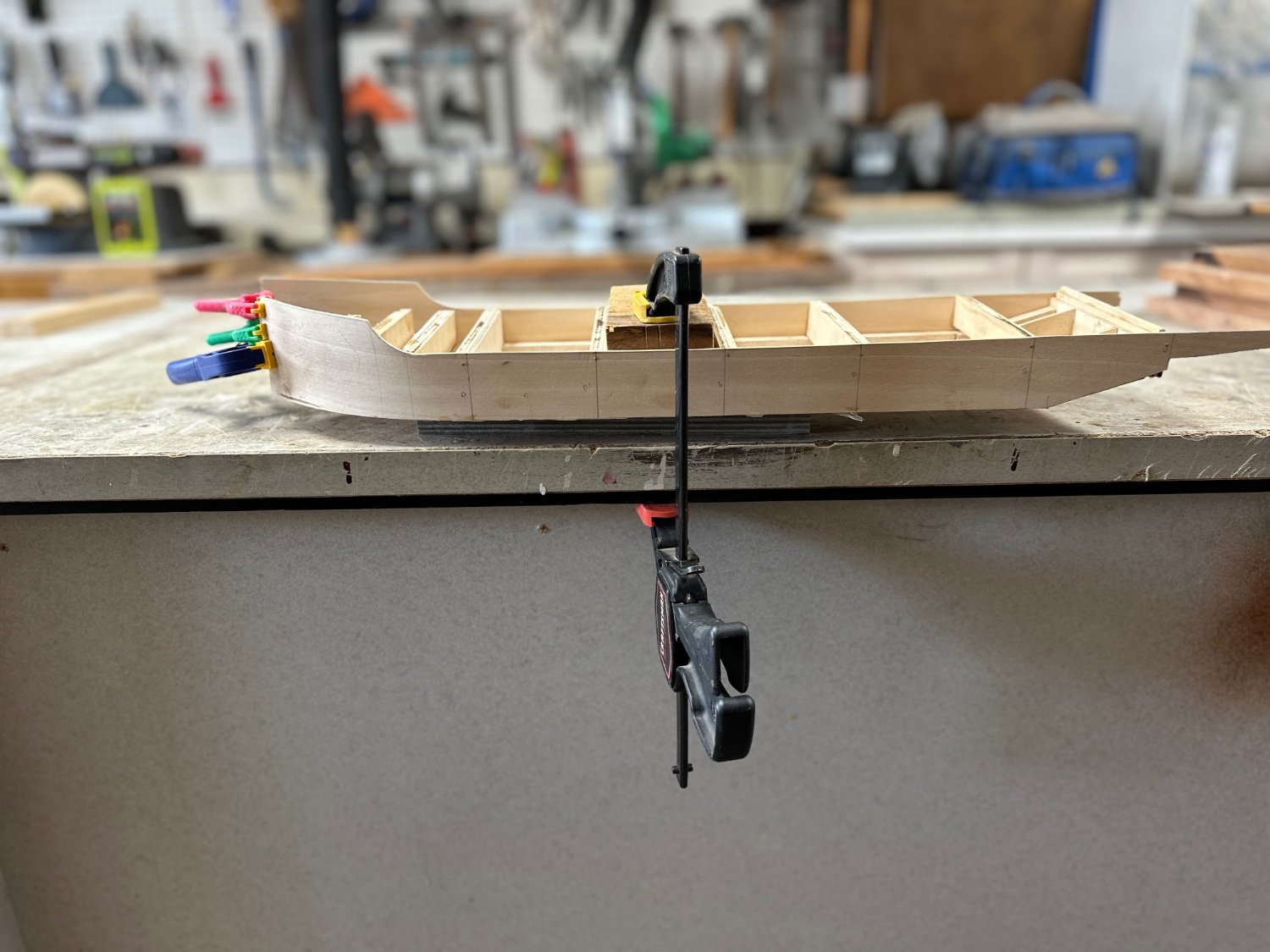
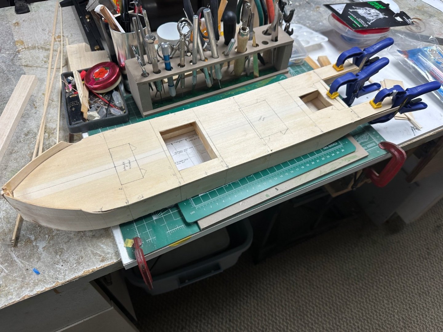
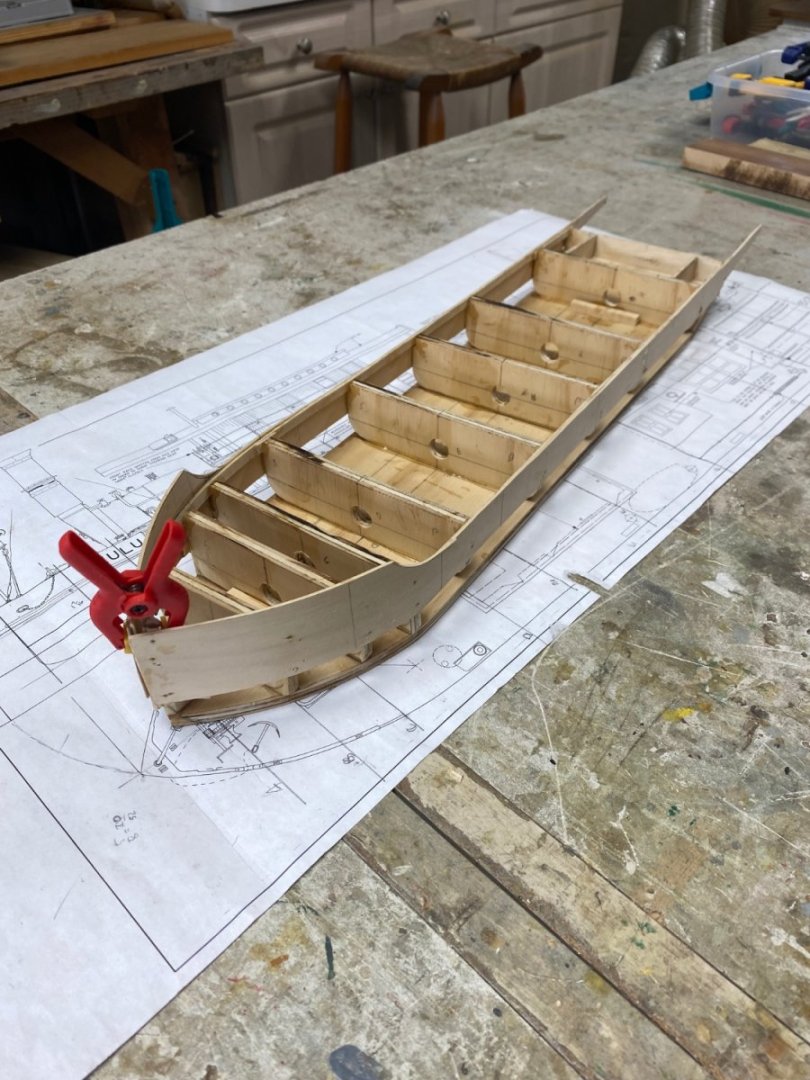
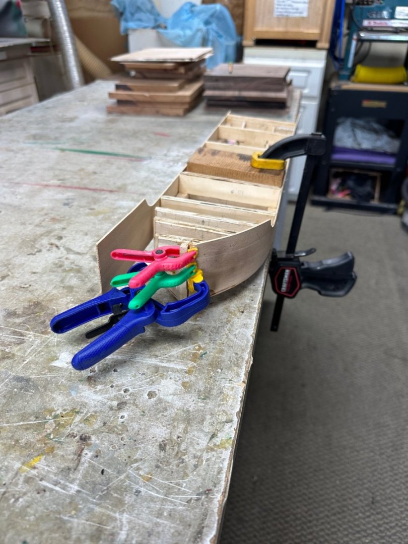
Wefalck and Ives, thanks for your comments. This paddleboat design has been in my mind for years. Finally, I got it started. However, things didn't go well at the start. The Sarik prints were huge and the calculated scale was 1/18 rather than the advertised 1/24. Since I wanted the model not to exceed 30 inches in length, I had to have them reduced in a print shop. Thanks God for the new technology. With the new plans at the right scale (1/48), I started the build by cutting down the bottom of the hull shape in a piece of 1/4" ply. Then, fabricated the frames taking the dimensions from the plans. Installed the frames using a centering dowel and, using the drawings as a template, cut the hull sides and glued them to the frames. Used 1/2" square balsa to fill the bilge line between frames. After both sides were installed, I started the bilge rounding using our bench belt sander. The round bilge was 1/2" quarter round and I had to sand down both the hard ply flat bottom and the soft balsa inserts. The sander is only 18"long and the hull is 22"so, I could not line up the whole hull on the sander. And that is when disaster hit. You can see below where the bilge line started waving. And this was at the beginning of the sanding. I could not maintain the equal pressure required to sand ply and balsa since I had to straddle the hull across the sander. But, since I have all the time in the world to play and I am building this ship for myself, I started a new hull and this time decided that the bottom would be flat, 1/8" thick and with just a little rounding (not the scale 1/2"). And following is the progress as of today. And the deck is dry fit. Thanks for following and I appreciate your comments PS: I am saving the twisted hull. I may do a deferent project with it. The gunboats in the Nile comes to mind 🤔


- 128 replies
-
- 10
-
-
- zulu
- sternwheeler
- (and 1 more)
-
Just found your build Nils. Great job on John Wayne's steamer. I loved that movie and look forward to your build. BTW, in your photos the ship looks much larger than what I would suspect HO gage was. Seems you are emulating Wefalk with the miniatures. Good work.
-
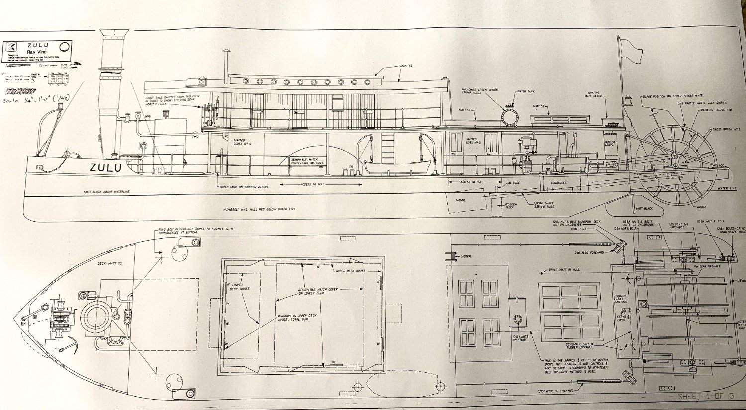
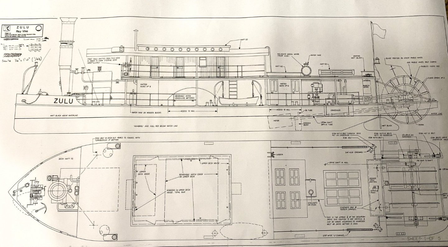
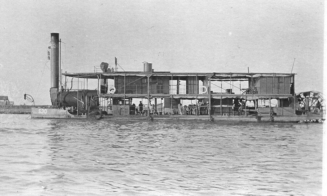
After completion of my B-17 and 1927 motorcycle models I am back to shipbuilding. Since I got more projects in my head than the lifetime left I have decided in building two projects at the same time. I expect to work in alternate weeks. The first one is this version of the paddle steamer Zulu and then I plan to do another bass profile on a 1/48 scale Spitfire. Going back to my times in The Netherlans I did a lot of work with live steam. Built a couple of R/C controlled live steam boats and always wanted to build a steam powered paddle boat. The problem was that these boats were quite large and required building at a very small scale that made it difficult for me because of my own limitation to produce parts at a very small scale. Using the forums. inspiration I have been able to go from a tolerance of 0.5 mm to tolerance of 0.25 mm which allows me to do acceptable detailing down to 1/64 scale. In doing the research I found this boat that at 90 feet OL will fit nicesely with my capabilities. The research on our site brought to my attention Kishmusl's 3D CAD model of Zulu. I already had previous information from an old issue of Model Boats (April 1982) that was written by Ray Vine and had a miniature copy of the drawing. I contacted Sarik and purchased a copy of the plans. When I received the package, I found 5 sheets of details at a scale of 1/18 making the model over 50 inches in length. I went to my local blueprint shop and got it reduced to 1/48 scale. A little background on the ship. Using the internet I did not found much regarding this particular ship. The closest one was this one built in 1916 by Alley & MacLellan in the Sentinel Works, Glasgow. The first owner was the War Office-Inland Transport Department with the name S-3 and it was in operation in the Nile and in Mesopotamia until 1932 Following is a partial description, by Ray Vine, of the plans: Quote History of the Prototype This type of boat was predominately used in America, Burma and India. Used in the latter two countries operated by the Irriwaddi Flotilla Company. Built in Glasgow most of these steamers were sent in parts and assembled in Rangoon. The steamer boilers were built in UK and dispatched as a complete unit ready for installation in the finished boat. The engines were shipped separately. As can be seen from the plan, the boat had a very shallow draft which, of course, is essential where steamers have to operate in the shallows and creeks of the Irriwaddi. Due to the shallow draft, which could be as little a 1'-8", it was necessary to position the boiler right forward to preserve trim, counterbalancing the weight of the engines and the paddle wheels aft. The tall funnel too is necessary to induce draught to the boiler. A forced draught installation being omitted to keep the weight of the machinery down to the minimum. These boats also operated in the Mandalay-Thabeitkyin route. End of Quote. More information is shown on the Steam Boats Museum website (steamboats.com) with pictures of another Zulu model in 1/24 scale. I would appreciate any additional information you may have on the history of these useful vessels.
- 128 replies
-
- 13
-
-

-
- zulu
- sternwheeler
- (and 1 more)
-
Thanks a lot Dan and all the other followers that inspire me. Love this forum🙂 Ras
-
Thank to y’all for your likes and comments. And, to Shipman, I will not run this bike past 10 mph.
-
Thank guys for you support. Next I am going to try to preset the model in four views: top, bottom, right and left. This will mean getting two identical kits. But, I also want to start on my next ship model. Decisions, decisions, decisions….?
-
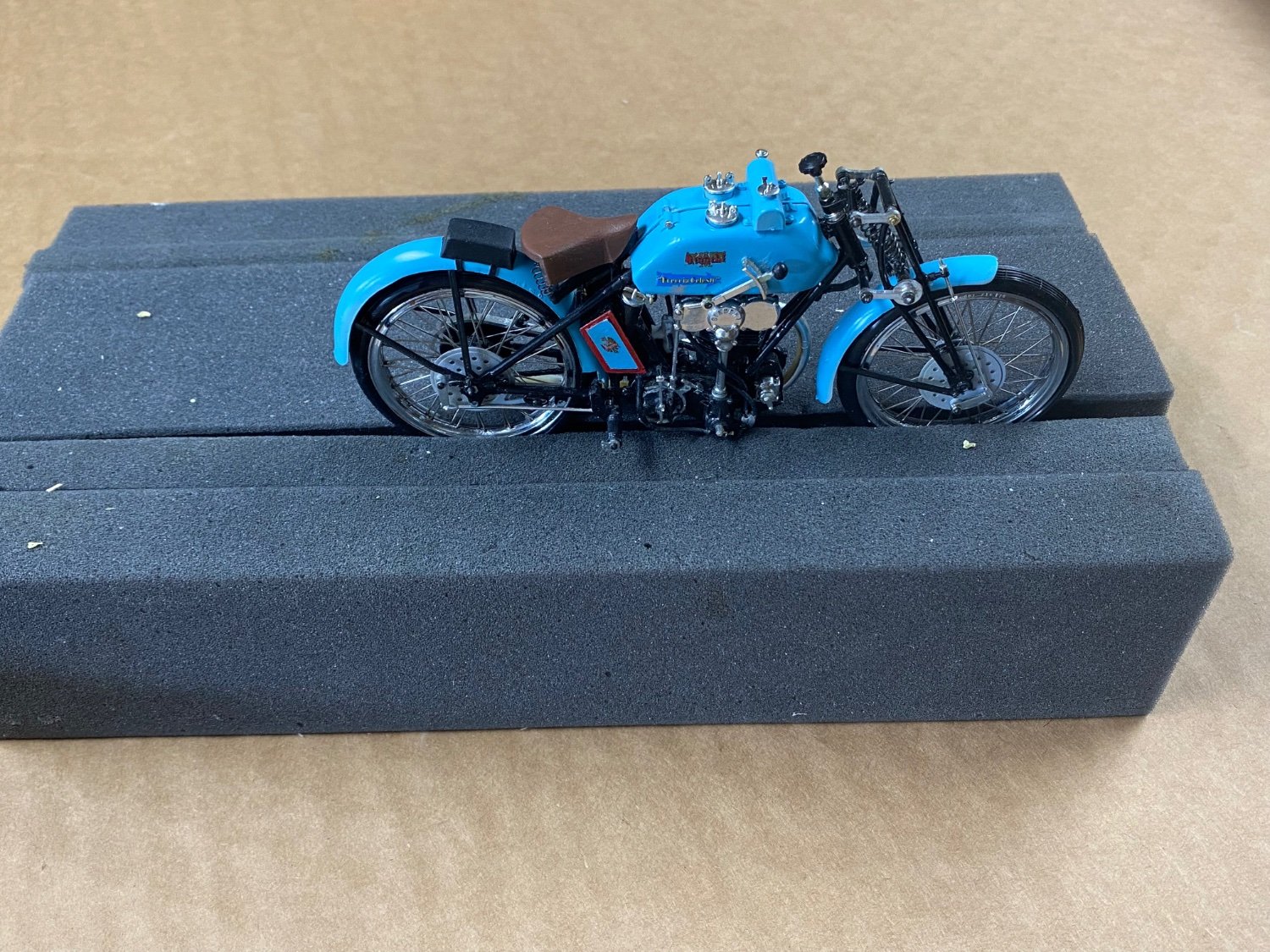
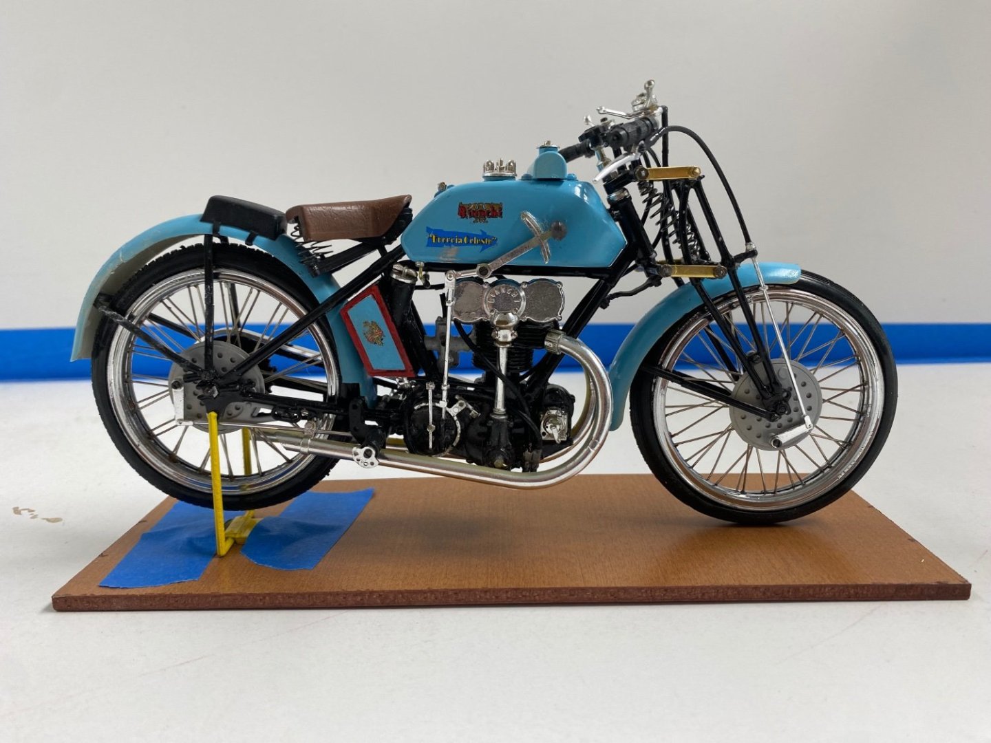
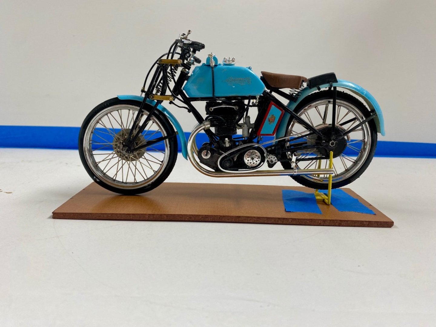
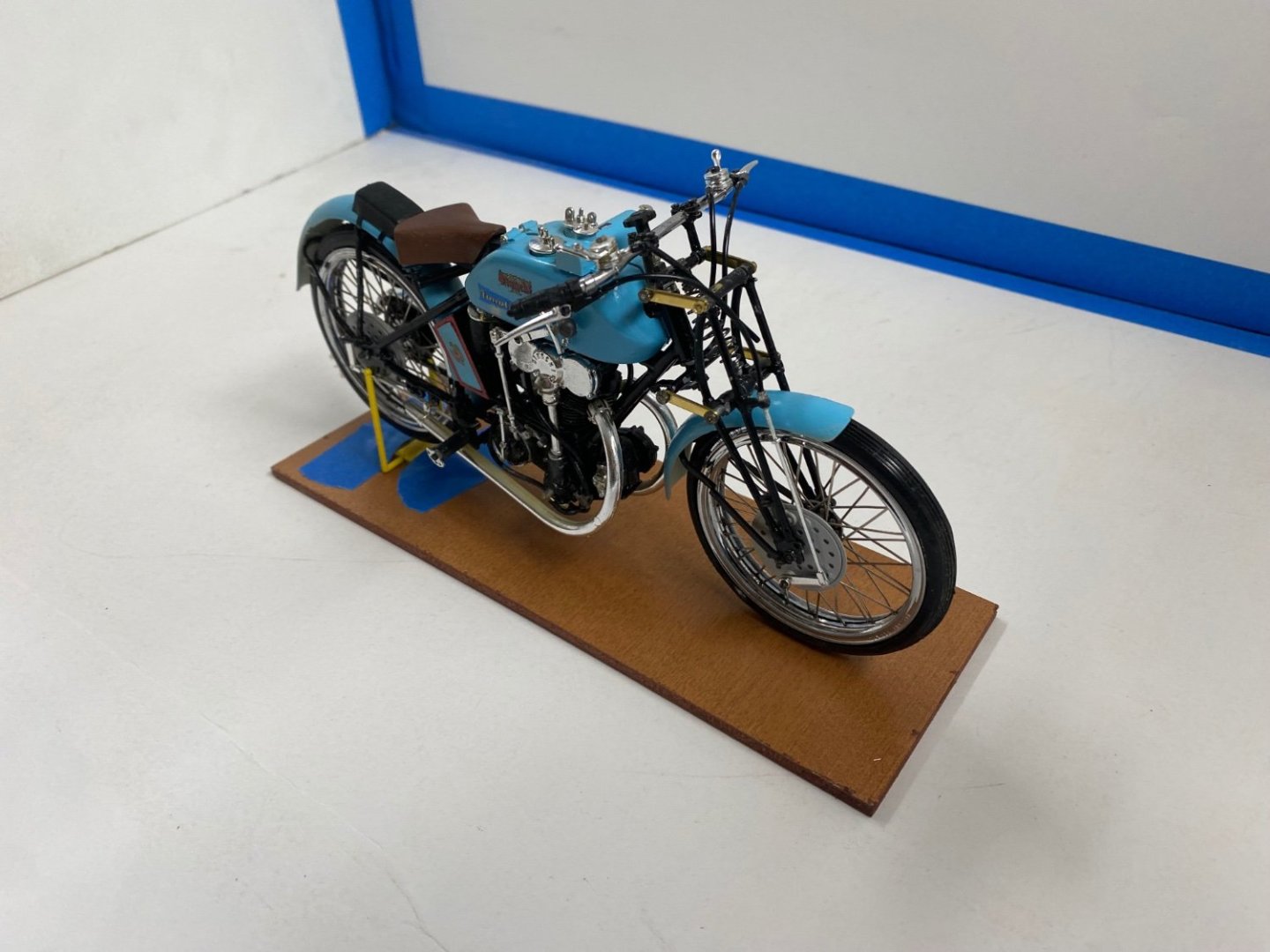
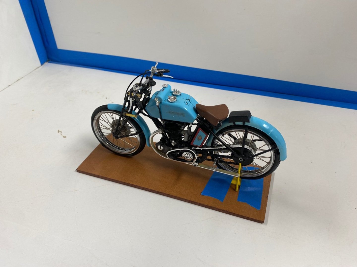
I am back. After the disaster I went into a hiatus to cool off and assembled a B17 model kit that I had in my shelves. That project is finished and I went back the Freccia. I fabricated new links for the front fork suspension but didn't like the results. I then looked into my little boxes of leftover materials and found a set of stay rigging chains that were the right size. With these I reassembled the front fork. It just happens that the damage to kit was a little more serious as part of the front and rear fenders here broken up. I fixed these items, maybe not very neatly, and preceded to complete the motorcycle by attaching the exhaust pipes, the handlebars and the corresponding control cables. The project is now FINISHED Moderator, please label this post FINISHED
- 126 replies
-
- 17
-
-
-
Same here😏
-
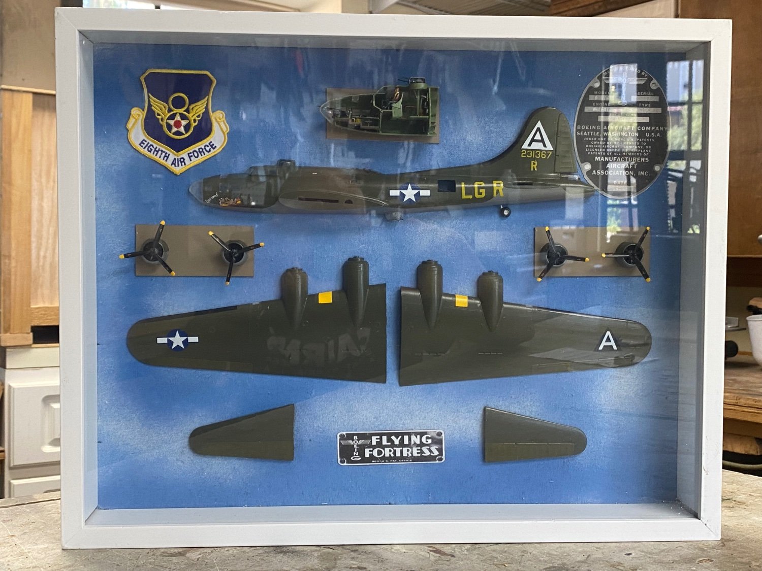
The final results: Project is now completed and the results of my "proof of concept" are satisfactory. Sorry that the glass in the shadowbox gets into the picture. To Moderator, please label this topic FINISHED.
- 10 replies
-
- 14
-
-

-
-
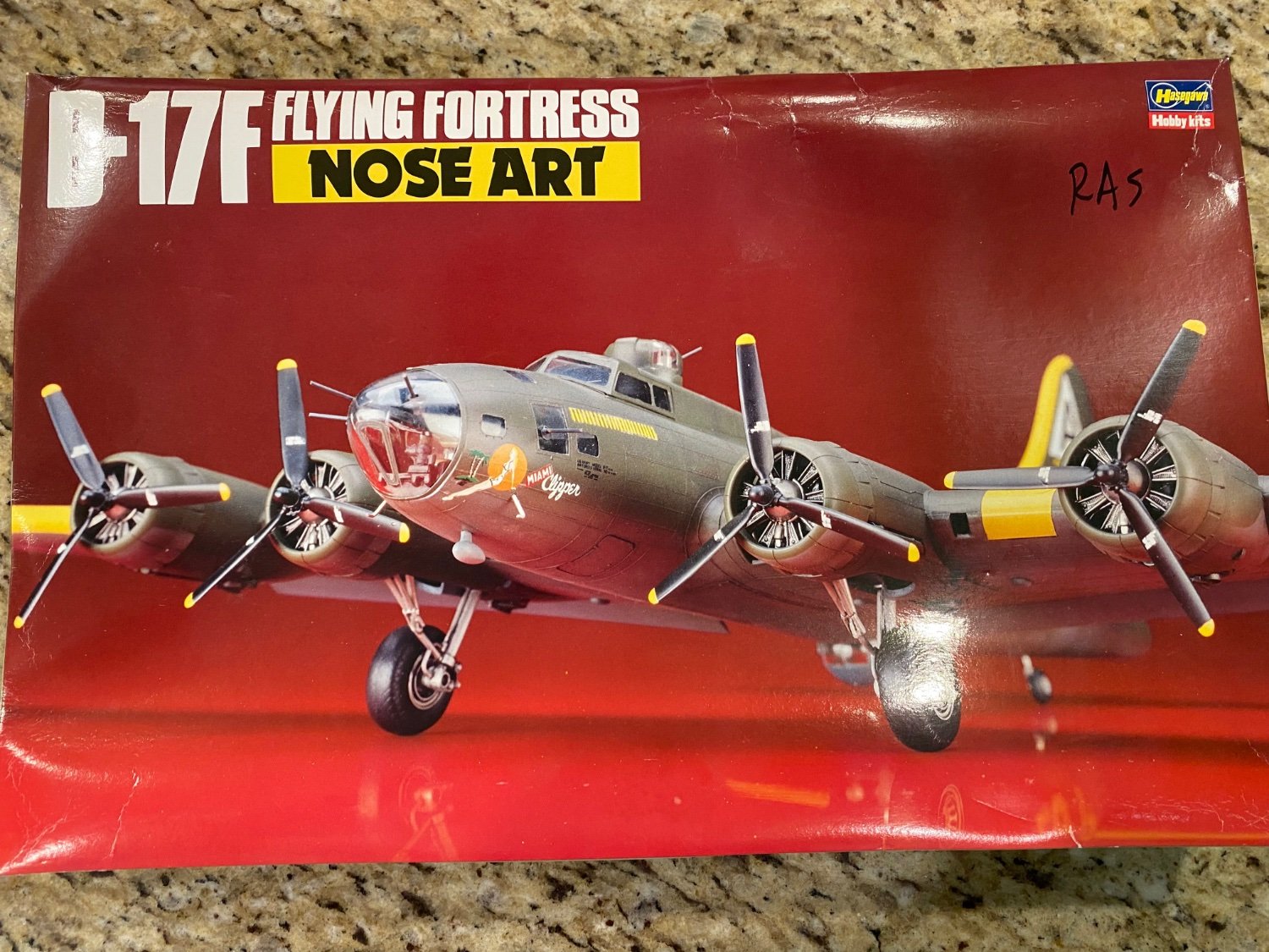
Moderator: Please correct the Kits manufacturer name to Hasegawa. Thanks
-
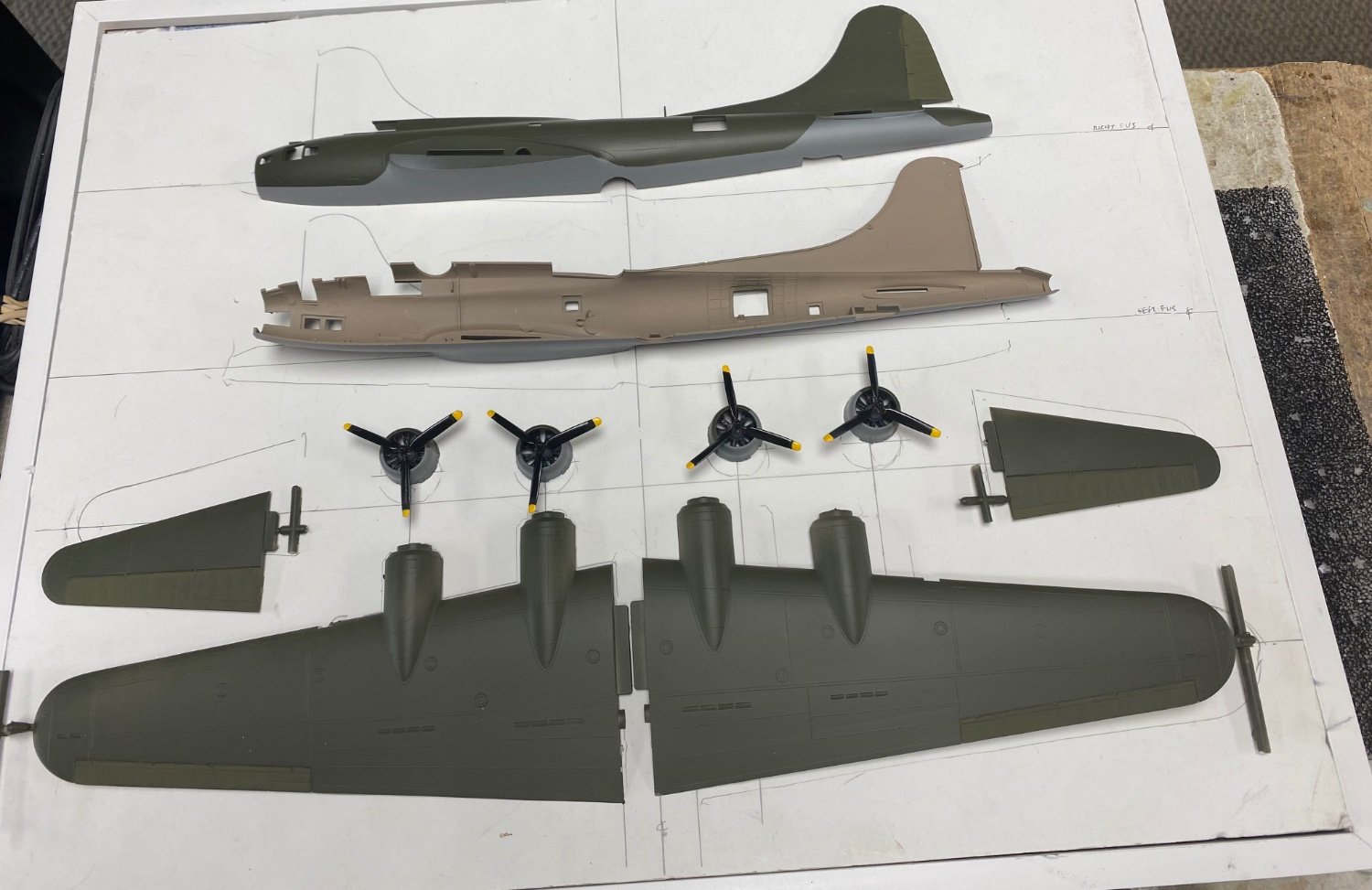
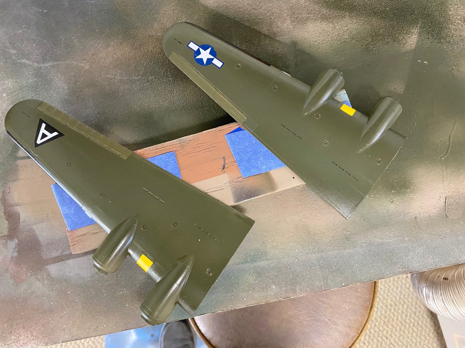
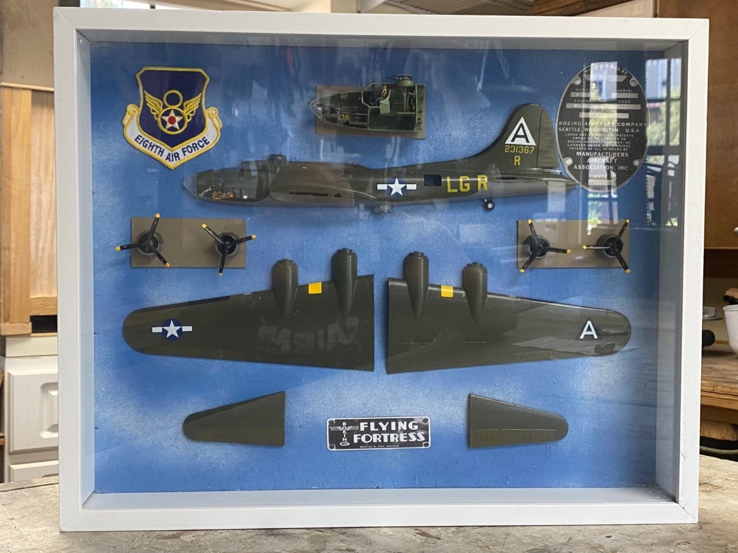
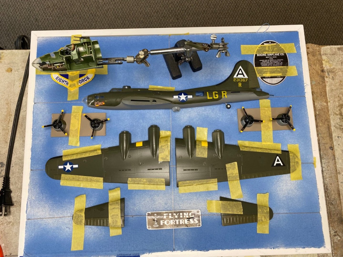
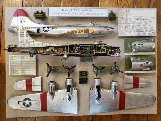
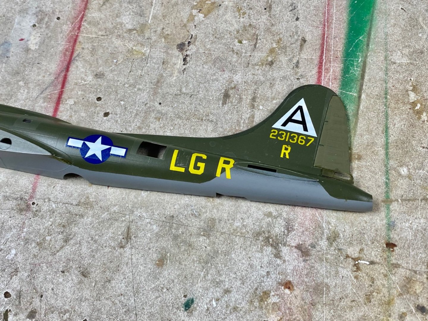
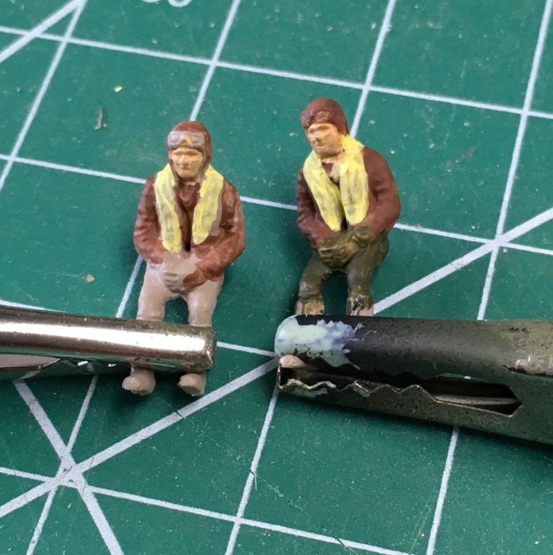
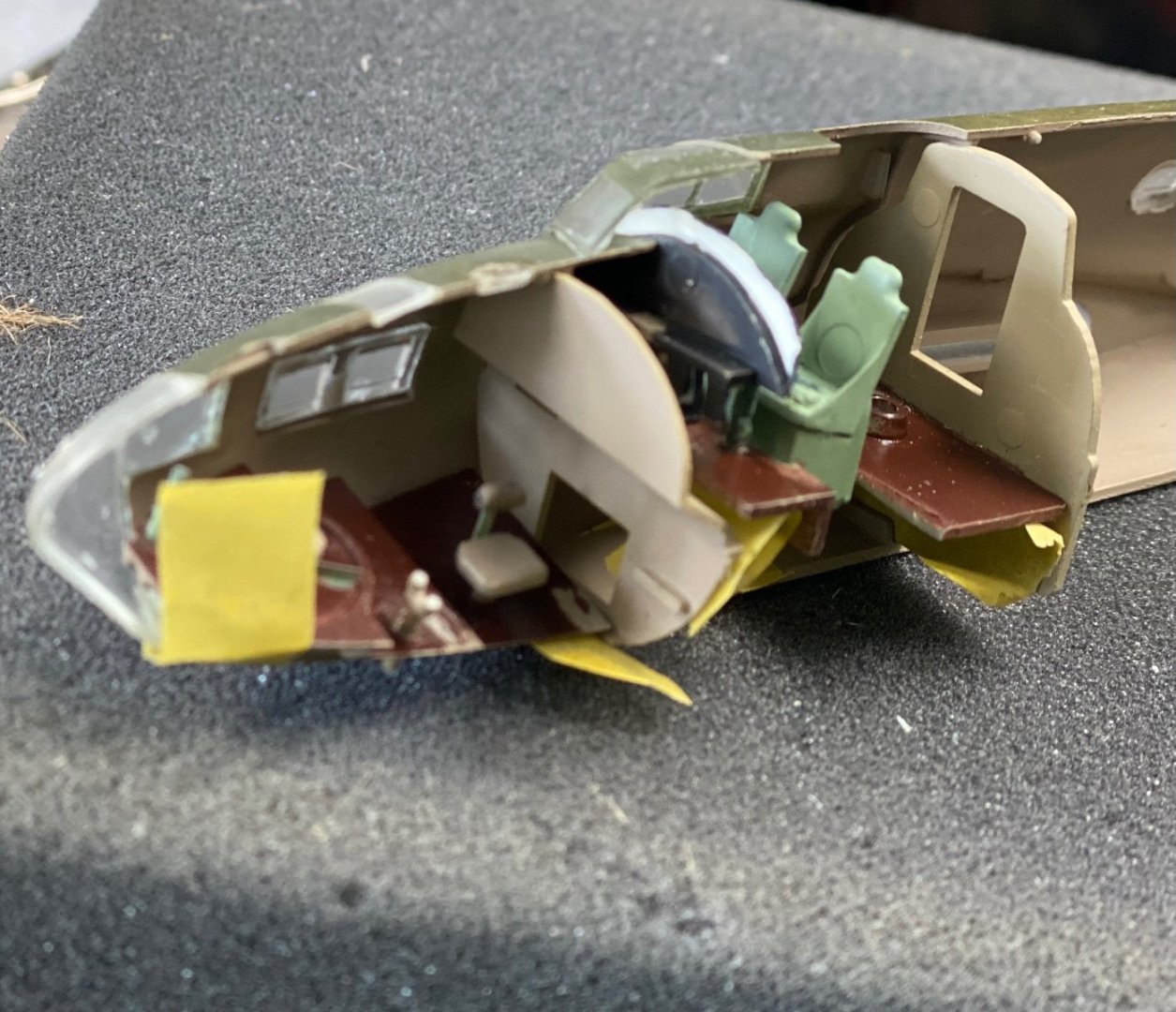
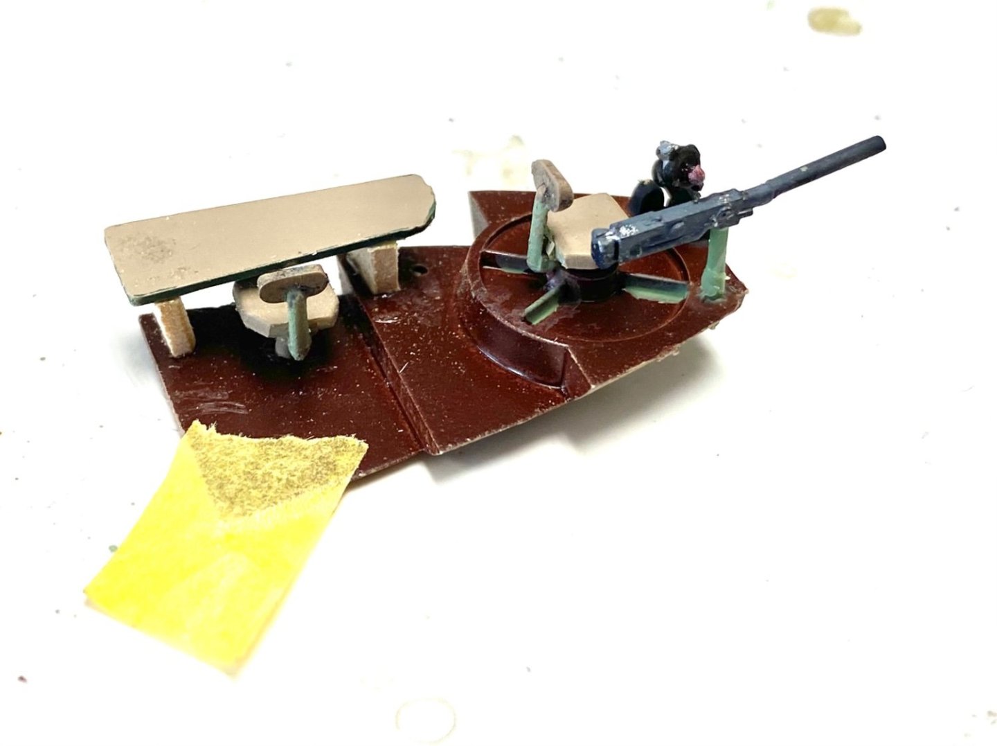
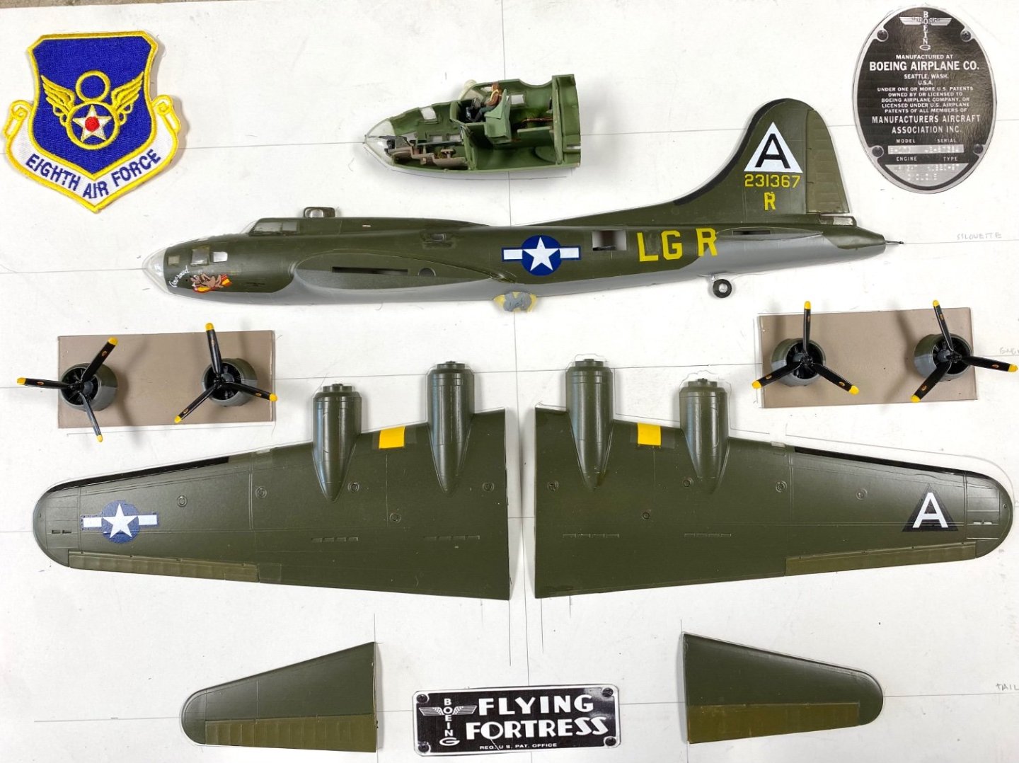
Alan, thanks for your comments. Ives, the ship's half hull presentations is what inspired me. Then, searching the internet I found out I was not the only one: Here is another example of what can be done: Amazing, isn't it? Now the deadline, as much as I hate deadlines, is approaching. This is my project as of today. Glued the pieces in the canvas sky but accidentally dropped the roof window on the radio cabin. So everything is waiting for glue to dry before going into the shadowbox. BTW, I want to share an idea I used today. I questioned drawing pencil lines in the canvas for the positioning of the pieces. What I did was to take the measures from my display board and using ship's rigging lines laid them in the canvas and then anchored the lines and tensed then behind the board using Tamiya tape. I tried to keep the glue out of the part edges where the line passed and I expect to pull the strings out once the parts are solid on the canvas. So, as of this morning this is my B17F:
-
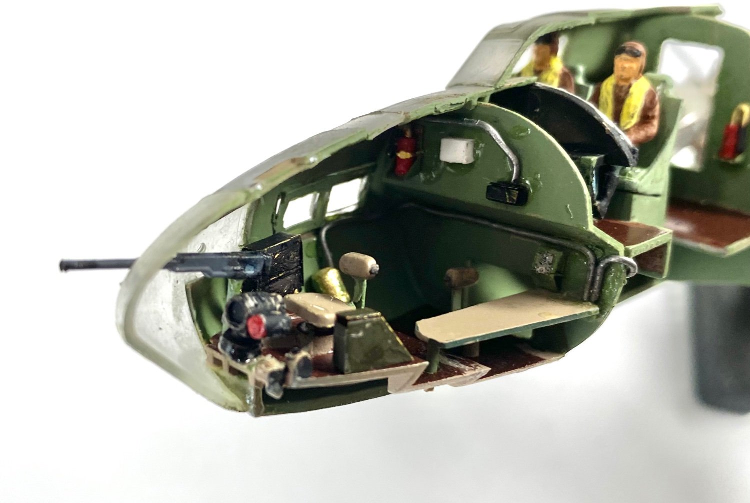
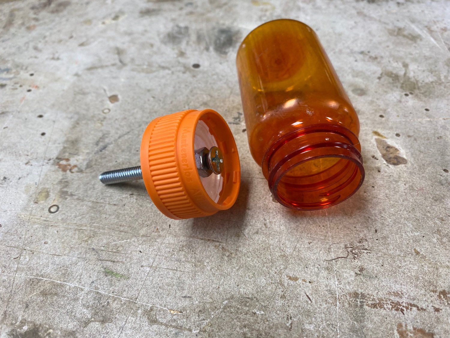
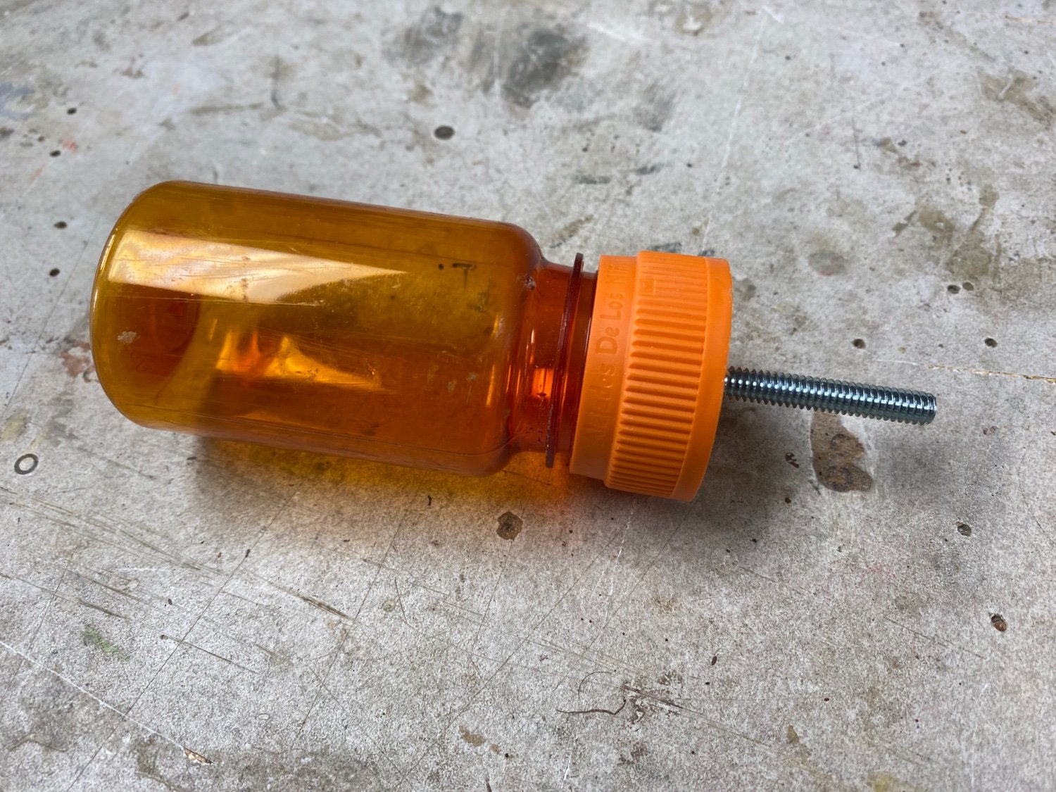
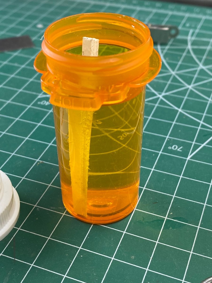
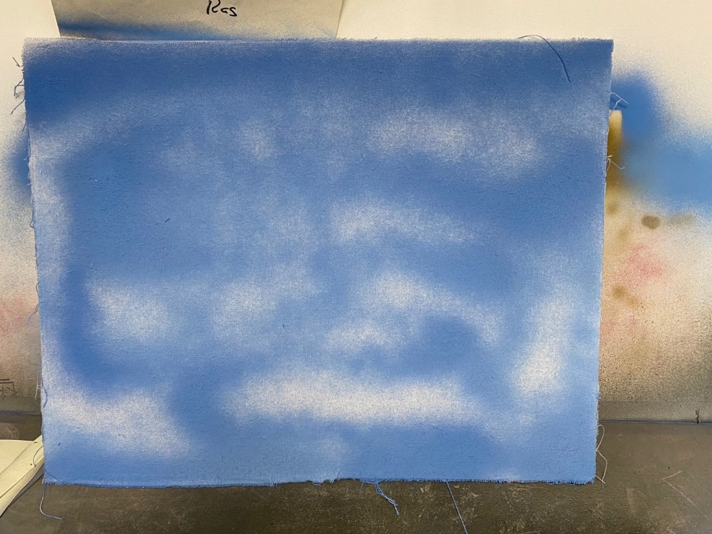
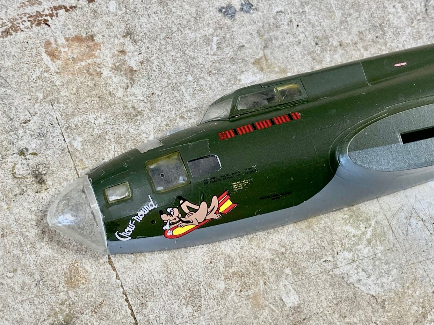
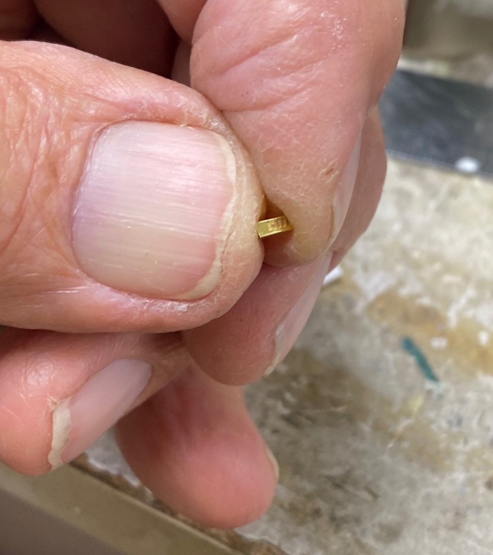
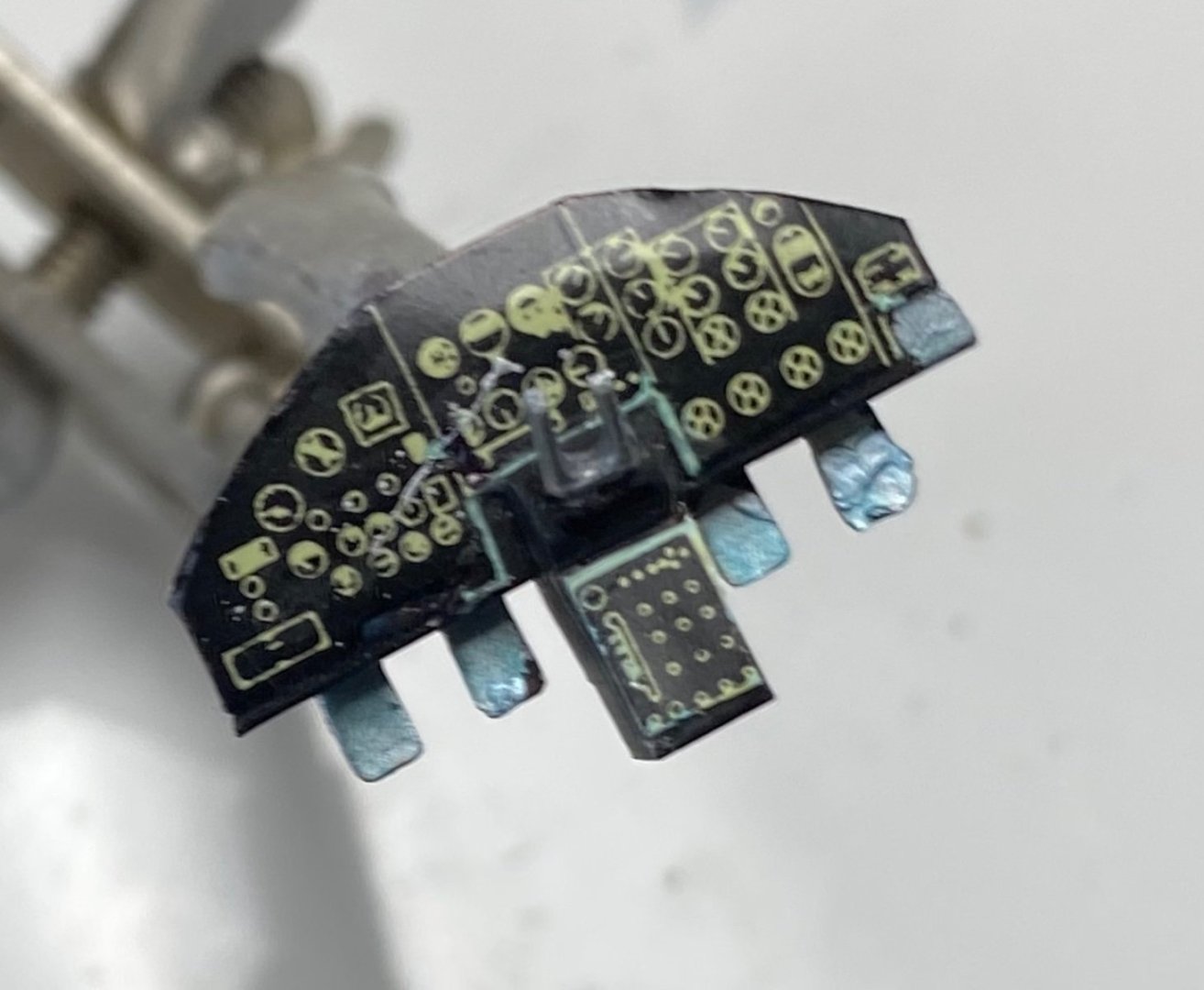
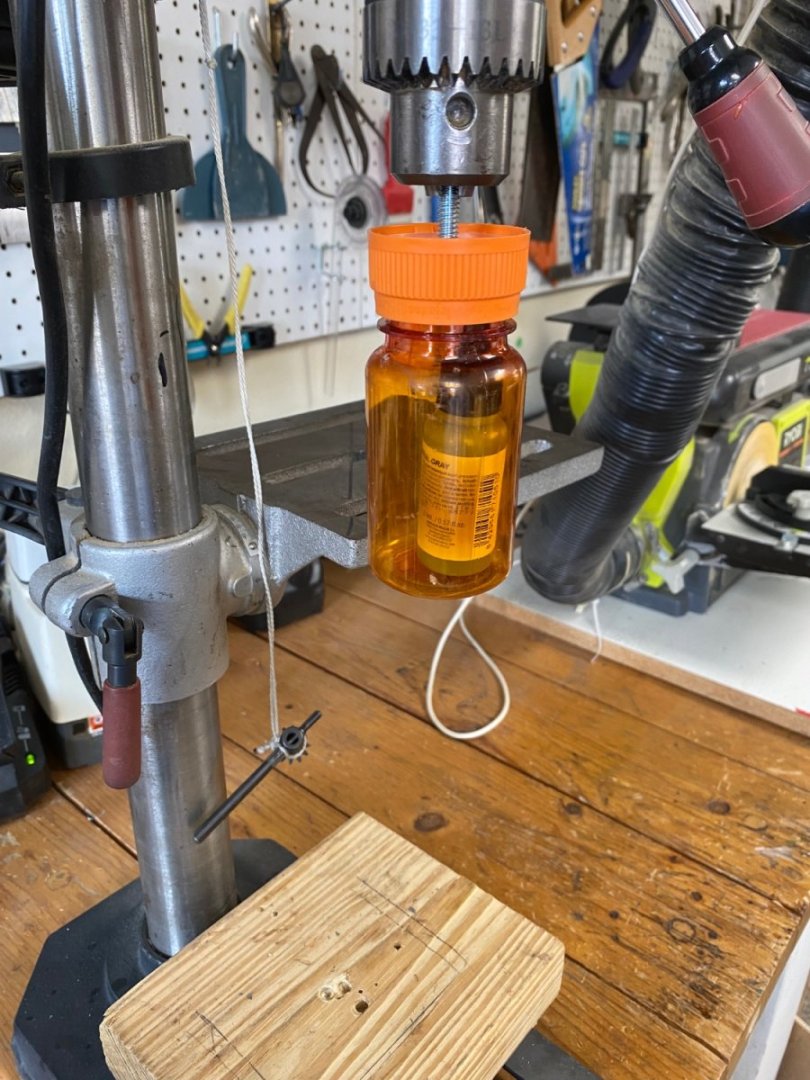
A few years back a friend gave me this kit of a B17F bomber. He was building a B36 in 1/72 scale and wanted a B17 to compare sizes. At the time I was busy scratch building ship models and just put the kit away in the shop shelves Then, after the disastrous accident I had with my “Freccia Celeste” motorcycle project, I needed to cool off. I decided to build this model as a "proof of concept" of a way to display airplane models in the walls rather than in shelves or hanging from the ceiling. My idea came of my collection of small booklets called “Aircraft Profiles” that presented the aircraft with profiles indicating painting and markings.The plastic models are offered in “flat” trees that resemble a Bas-Relief so I figured that I could lay the different parts of the aircraft in a “Shadow Box” display. During my online searches I found that I was not the only one with these ideas as several guys have done a similar job. So, I went to Michael’s and purchased a nice shadow box. The back was painted to resemble a cloudy sky and I tested the arrangement using the kit’s parts. I intended to super detail the inside of the Fortress and to purchase etched parts to complement the kits details. Following are photos of the build in progress I ordered the Edwards PE rear cabin details but, when I saw the size of the parts in the PE frets, I figured that 1/72 scale was way beyond my tolerance and decided to use the parts in the kit and some of the PEs to detail only the cockpit and the bombardier/navigator station in the nose of the aircraft. The fire extinguisher was scratch built. And this is the project as it stands today. I need to go back and retouch some of the outlines but, other than that, I am pleased with the results. Be gentle with the magnifiers as I am not a very good painter. But, from the middle of room looking at the wall it will be fine. Tomorrow, I expect to mount it on the canvas and set it in the shadow box. It is going to go on exhibit at the Art Show our building is having next week. This is where we, old "f**ts, show our playthings. Now a note for modelers: While building this kit I used Vallejo paints and found they are difficult to shake by hand. So, I came in with a new tool: “The Ras’ Shaker” using a large prescription container. I originally made this for rounding up wood ship's blocks when sandpaper is placed on the inside circumference .Works like a charm. Thanks for following.


- 10 replies
-
- 15
-
-
-
Sorry I couldn’t be of more help to you on the African Queen model. I built mine many years ago before I joined this forum. I remember it was a fairly easy build until I tried to run it on steam. The little oscillating steam engine wouldn’t move the boat at all. So the I cheated by disconnecting the steam engine and adding an electric motor. The boat then ran perfectly. I could fire the boiler and get the steam going while the electric motor did the work. Very satisfying experience..Good luck on your build.
- 57 replies
-
- 10
-
-
- live steam
- radio
- (and 2 more)
-
Sternwheeler "Zulu"
Ras Ambrioso replied to Kishmul's topic in CAD and 3D Modelling/Drafting Plans with Software
I just ordered the plans for Zulu from Sarik Hobbies and will be using your 3D drawings to scratch build the model. There is not much information online for this boat. I will start the build log as soon as I get the plans fro the UK. Great job bringing all these details to live. -
Great job. The only thing missing are the flowers. Maybe you could get some miniature flowers. You may try the net for places that sell material for doll houses. Here, in the USA, we have Hobby Lobby and Michael's that carry such stuff. Pero, en todo caso tu trajinera es bella.
-
By the way Jacques, are you also a diver? I used to dive in Cuba with the aqualung just after Jacques Cousteau wrote his famous "The Silent World".
-
Jacques, I am enjoying reading about your journey through you first scratch built. Your story telling is great and told me about a few things I didn't know. I have have been in Mexico City in many occasions and had the pleasure of enjoying the rides at Xochimilco. The one thing that was notable in the "trajineras" at the park was how colorful they were. Flowers all over and brilliant colors. I will be following your build. Que viva Mexico
-
Great emoji
-
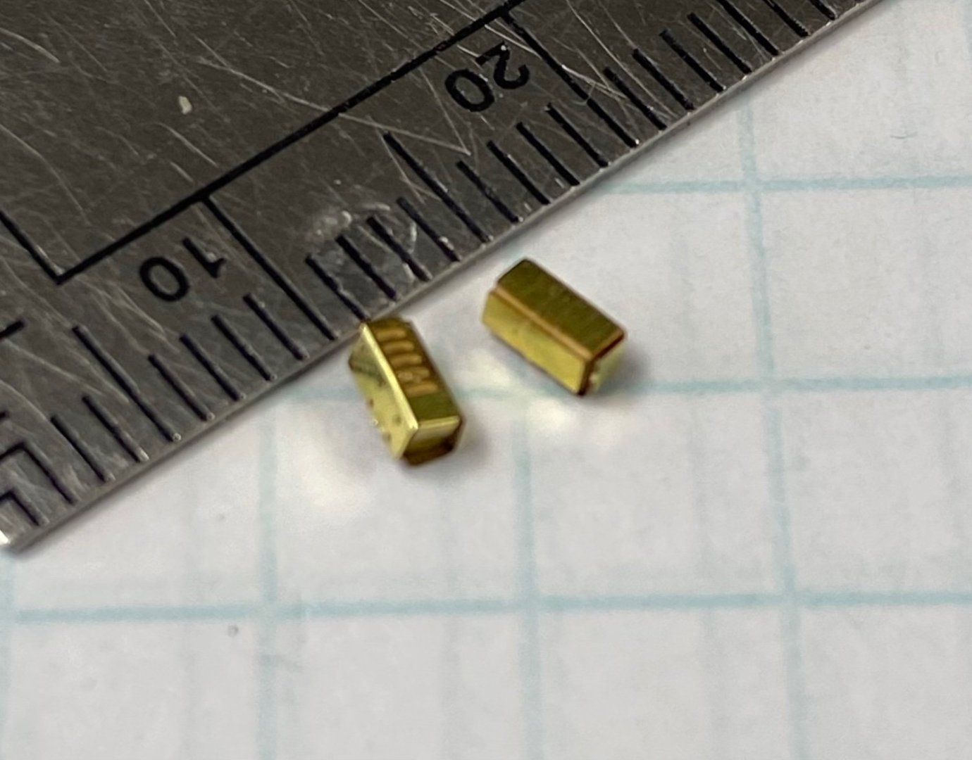
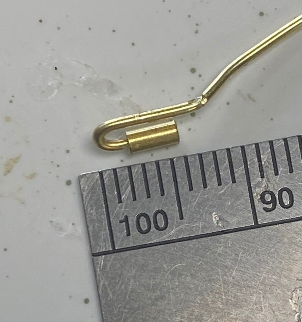
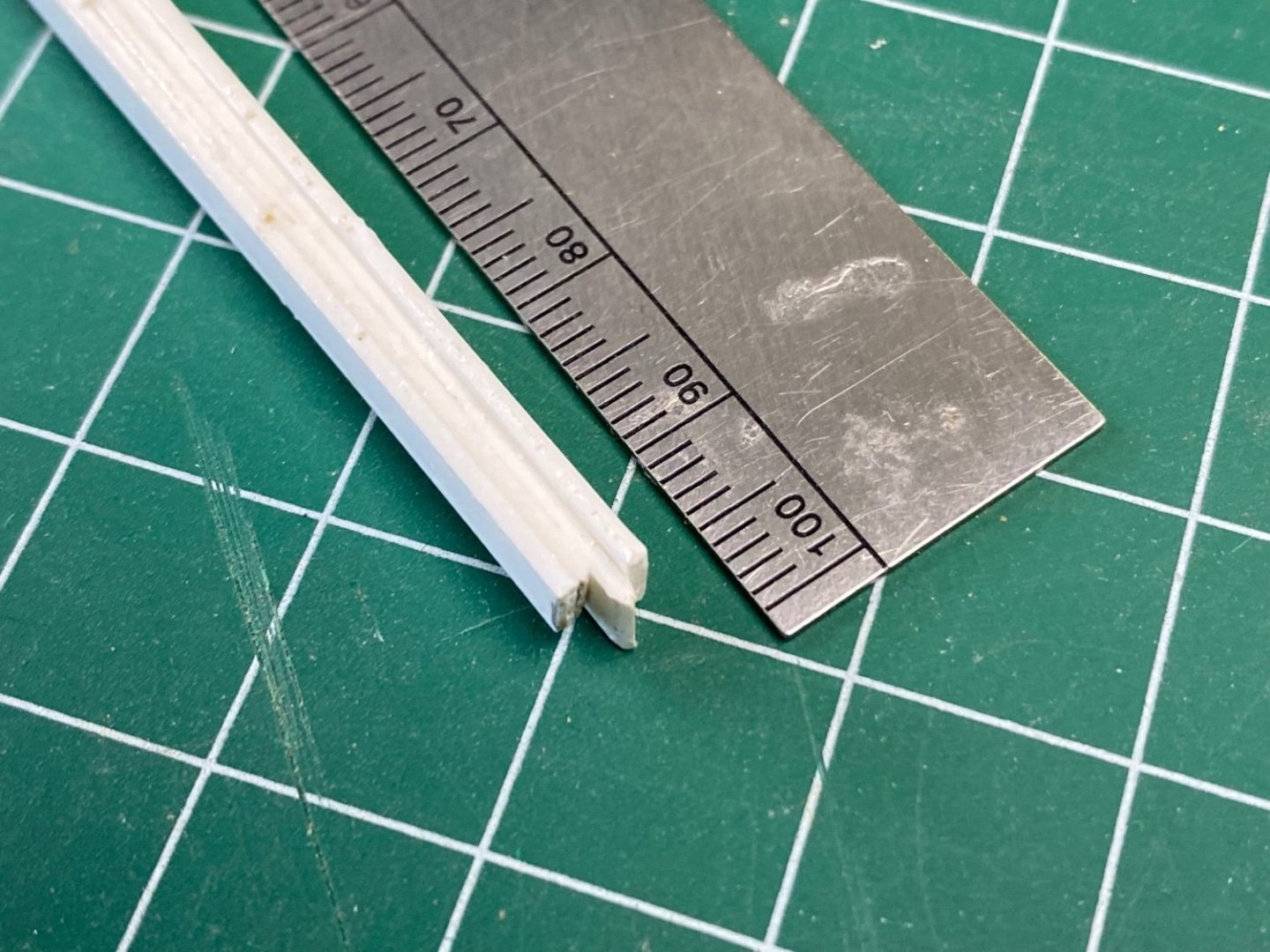
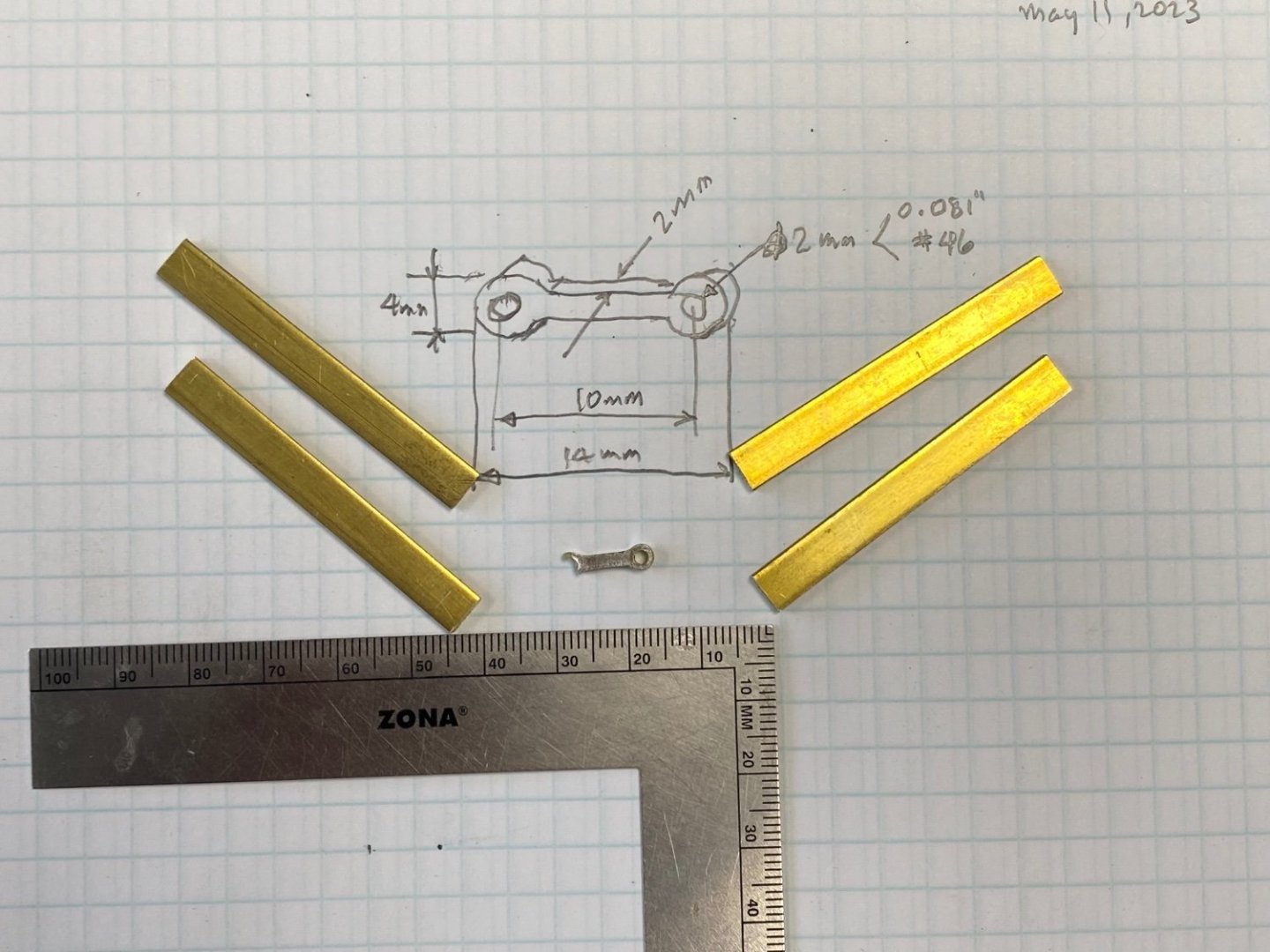
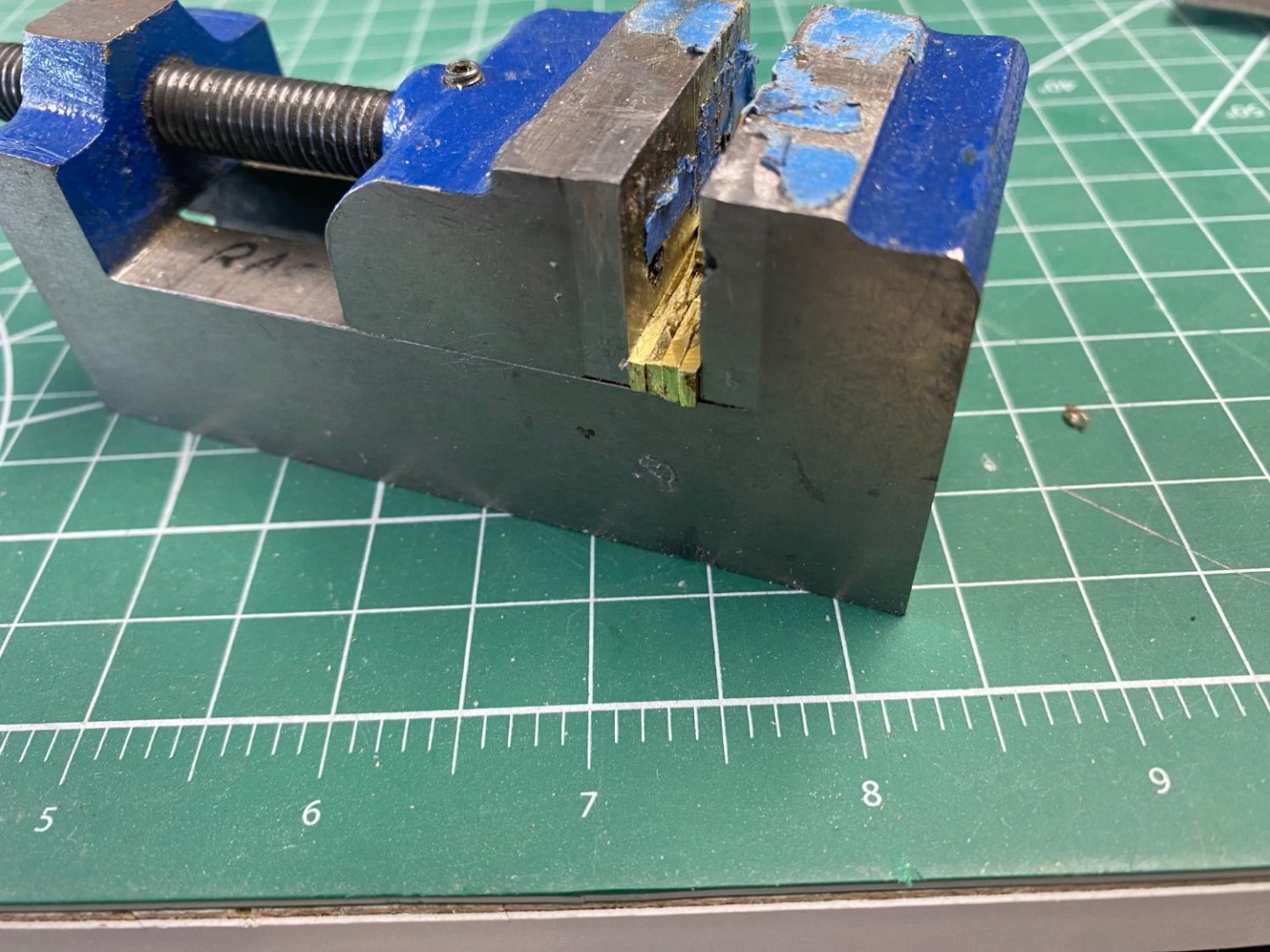
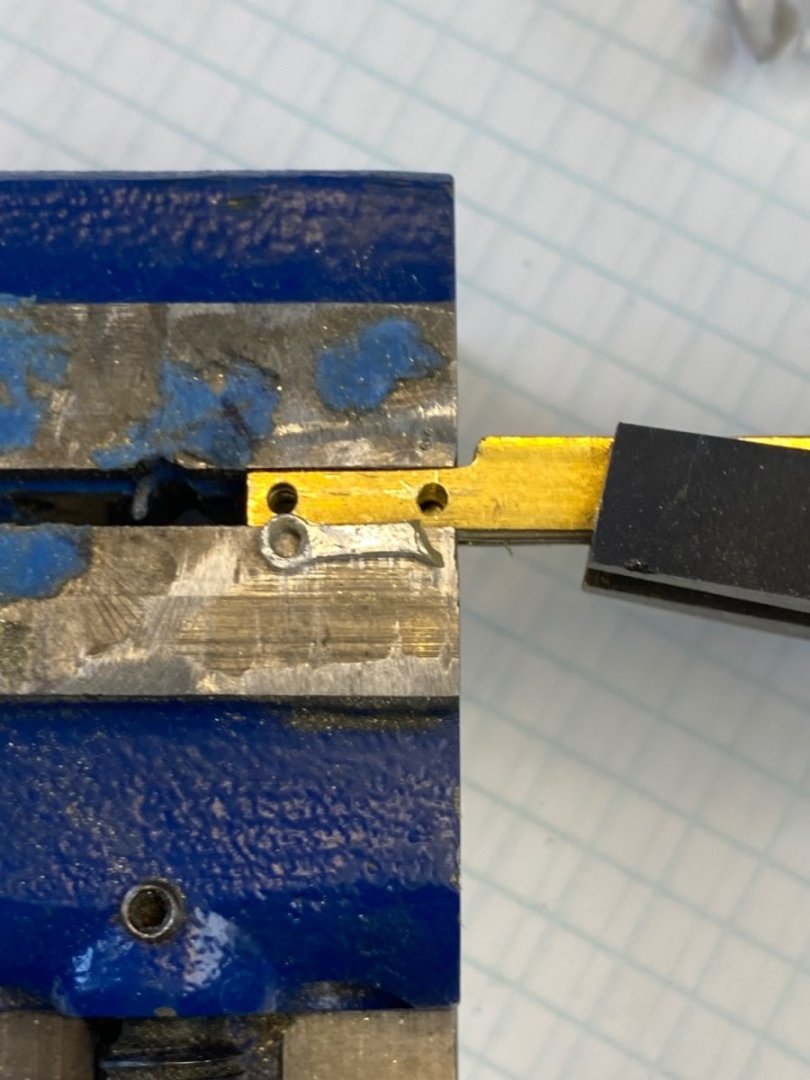
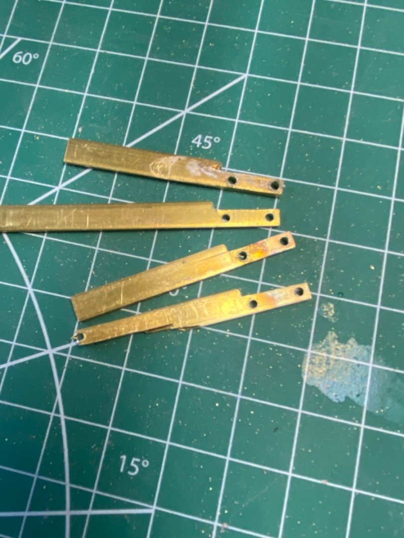
Well I finally cooled down from my disappointment at crashing my, almost complete, model. I used this time to embark in another project which I will be logging soon. As I have shown before, the breakage included the connecting pieces between the frame and the front fork. Rebuilding these parts seemed an easy job and I decided to use some styrene strip that I had left from the Mimi project. I needed 4 pieces that had to be exactly equal since they formed the parallelogram that allows the movement of the front fork with respect to the frame. In order to make four similar pieces I decided to glue four strips and work the drilling and shaping in unison. I would use Elmers glue and, when the fabrication was completed, I would de-glue the strips with alcohol. Great idea, Ras. This was the test of the process. Then I dipped the bunch in the de-gluing liquid. The next day I removed the bunch from the liquid and ...... Horror again. I had a melting goo instead of four nice separate strips. A little investigation resulted in finding that I had used acetone instead of alcohol. Another senior moment. Then I reconsidered the problem and decided that metal would be a better material for this stress are in the bike. Using the the same idea of fabrication in unison I could use superglue to bind them during the drilling and shaping and then use the acetone to separate the pieces. Great! I measured the connector and cut four pieces of brass strip 6X2 mm. As planed, I glued with CA and let them in the vise overnight. Then with a file I brought the bundle to size marked the holes and starting the drilling of the two holes. Now, guess what........ Horror again. The heat of the drill unglued the strips and ruined the job. I then started again with a new set of strips and this time I clamped them together during the drilling. And yes, finally, success: Now I will shape them using my hand tools. The saga continues, next comes the handlebar and the bottle of champagne.

- 126 replies
-
- 13
-
-
Fantastic. I see you found the scale match LOL
-
Thanks for the encouragement, guys. See you soon.
-
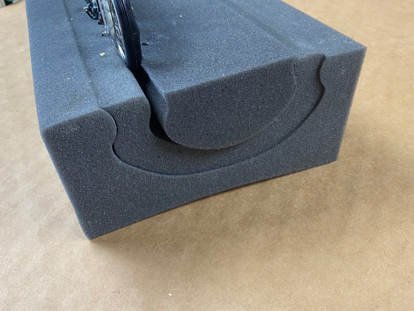
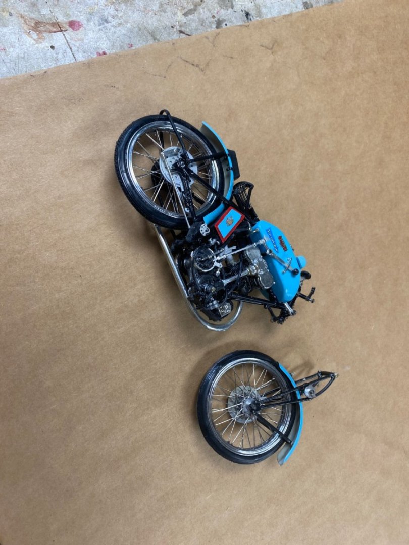
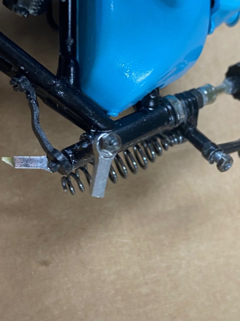
While I was working on the finishing details of the motorcycle I was using a block of foam that I bought from Micro-Mark. This block was used to hold the ship's hulls while working on the superstructure. I found that I could lay the motorcycle on the top of the block setting the foot holds in the crack. The arrangement worked perfectly. Now I am ready to install the completed handlebar (See Post #28) and attach the control cables to the ignition, shift and brakes. So I figure in using the same block to stand up the bike. Here is the bike in the block: Here is the end view. The block is precut to use on three different size hull beams. Very useful tool. Then disaster struck. While changing the bike's position for the photos, I dropped the bike and the "Bianchi Curse" struck again. I have tried to build this bike since the 90's when I built the spoke wheels and found the kit quite difficult; so, I abandoned the build and put the kit away. Then,in 2017, we downsized and I got rid of most of my tools and kits. In 2021 I found the same kit available online and proceeded to purchase it at quite a high price. I decided to start in another place other that the wheels. At that time, I assembled the frame and painted all of the body parts in the sky blue color. Then, when I joined this forum and started building ship models, I put the kit away . The kit sat in a shelf in my closet. This year(2023), while searching the forum, I found the "other than ships" section and my interest in the Bianchi was reborn. And now the "curse" hits. It seems that I am not supposed to finish this project. But, if Valeriy can work his magic in his hometown situation, I can rebuild the broken front end too. As you see on the last photo the front fork broke at the suspension parallelogram. I will use brass to rebuild the four connecting bars. I am going to take a couple of weeks to cool off working on another kit model (a B17F bomber in 1/72 scale). See you soon