
HOLIDAY DONATION DRIVE - SUPPORT MSW - DO YOUR PART TO KEEP THIS GREAT FORUM GOING! (89 donations so far out of 49,000 members - C'mon guys!)
×


Egilman
-
Posts
4,379 -
Joined
-
Last visited
Content Type
Profiles
Forums
Gallery
Events
Everything posted by Egilman
-
 Yes, It was a combination of rattle can for the base coats and brush work for the details..... Thank you.... I'm happy you like it......
 -
Coming from you Dennis that's high praise, Thank you Very Very much....... I'm very pleased you like it..... Thanks Everyone for the likes and compliments, it is greatly appreciated..... EG
-
Thank you OC.... Thank you very much.... Glad you liked it.....
-
Wow! Fine Bird!.... I"m partial to reverse Lend-Lease machines and this is a top example...... Nice job!
-
Thank you my friend......
-
Details are slowly coming.... RL is trying to derail me right now..... But I'm sticking with it to the end....... :-)
- 123 replies
-
- 14
-

-
Revell Tie fighter - 1:110 by Fnick (Finished)
Egilman replied to fnick's topic in Non-ship/categorised builds
No he referring to the surface the two different lacquers put on a finish, Matt Lacquer is designed to break up a smooth surface so it doesn't reflect light, where gloss lacquer is designed to smooth a surface so it reflects as much light as possible.... What he's contemplating is spraying the dry matt lacquer with high gloss lacquer nd see if correcting the finish will allow light to pass... I've heard of this before but I think it depends on which lacquer formulations were used... Lacquer from 30 years ago (true lacquer) crazes clear surfaces, that is unrecoverable. The current crop of Lacquers are not chemically true lacquers, but they act like them.... you might be able to restore it by recovering with the correct lacquer, or even stripping and removal of the lacquer...... At this point being covered with matt, it doesn't look right and never will... another option is if the kit is a round two model, and is in current production, you can get the replacement part fairly easily...... I hope this explanation helps you come to a resolution.... Other than your question on the finished windows, Beautiful model... nice work... -
1931 Cadillac by CDW - FINISHED - JoHan - 1:25 Scale - PLASTIC
Egilman replied to CDW's topic in Non-ship/categorised builds
Beautiful plating job..... These old cars do hold their chrome well.... Classic rumble seat roadster... Can't wait to see it finished.... -
Thank you OC.....
-
Citroen Traction Avant by kpnuts - FINISHED - Heller - 1/8
Egilman replied to kpnuts's topic in Non-ship/categorised builds
I'm getting flashbacks to the junk yard I worked in as a young man starting out...... Beautiful work....... No, Stunningly Beautiful work...... -
I"m glad you like it Kurt... Thank you
-
Thank you Ken....
-
Thanks Lou...
-
Bell UH-1H Huey By lmagna - Dragon - 1/35 - PLASTIC
Egilman replied to lmagna's topic in Non-ship/categorised builds
Looks good to me, OD green, especially US Army OD Green, can show up in many different hues and shades.... this is showing up a bit pale in the close up flash, but in the background under the yellow light it looks perfect for sun faded OD Green.... Nice work..... -
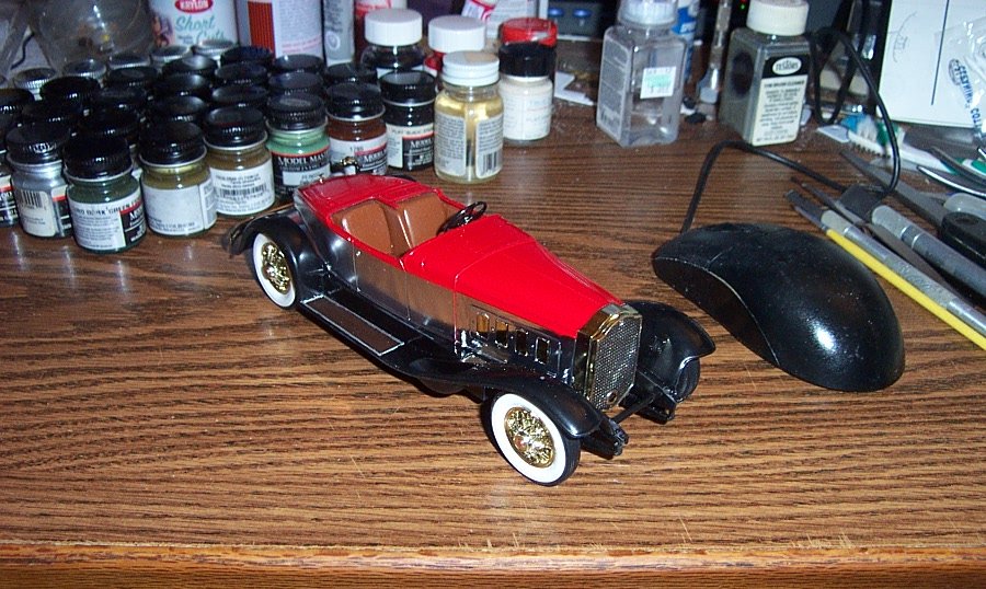
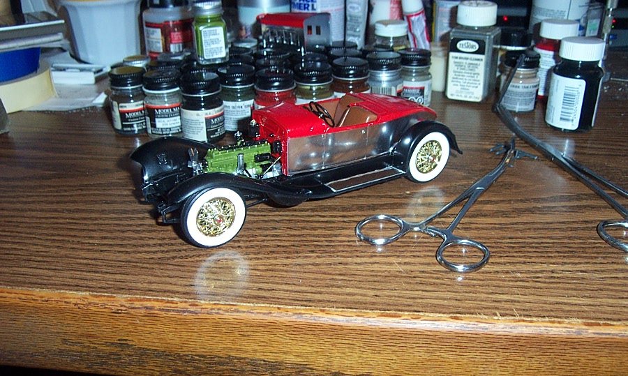
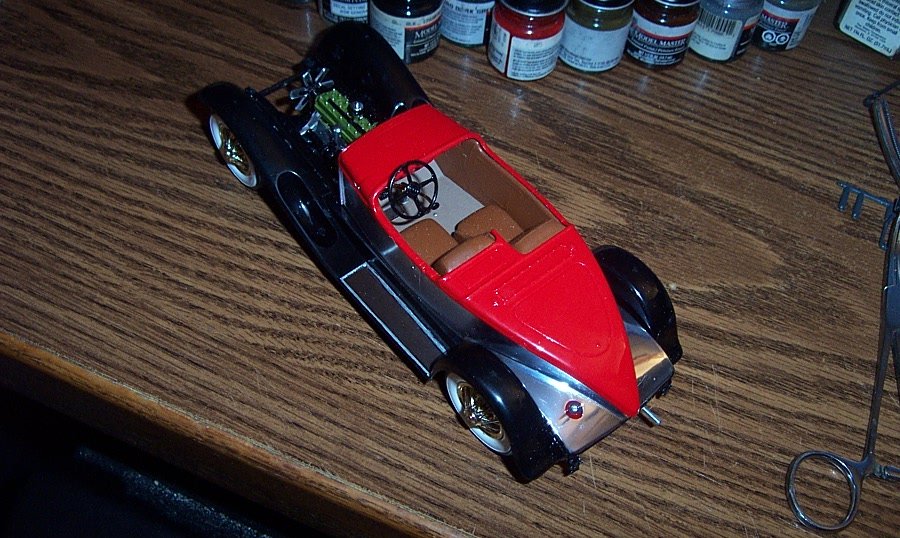
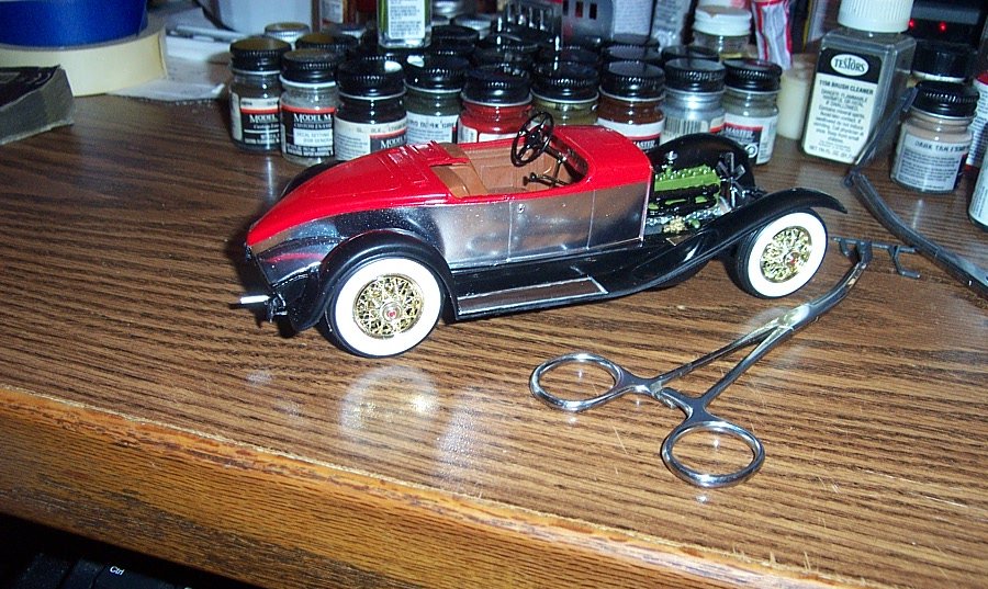
Well, finally got two coats of Model Master Ultra Gloss Clearcoat Lacquer on the body and hood.... One of the things I discovered 35 years ago is with these Metal Master kits, when you hit the soft chrome with a solid coat of lacquer clear, they turn into mirrors.... (you can easily see the reflection of the forceps on the table in the side of the car body) Top Rear..... Opposite side, now the chrome on this kit was not as clean as the chrome on the last one I built you can see the spottyness of it behind the rear fender here, it's not real noticeable on the model itself but it does show up under intense flash from an oblique direction... Anyway, major construction is done, now for the details..... EG
- 123 replies
-
- 18
-
-
1931 Cadillac by CDW - FINISHED - JoHan - 1:25 Scale - PLASTIC
Egilman replied to CDW's topic in Non-ship/categorised builds
The original molds were outstanding...... I saw no need to re-wire mine either.... -
Well, I guess I'm going to have to stop reading about General sherman to watch a general sherman..... pulling up the ol' three legged stool.....
-
The Garland ventilator is an example of the Coanda Effect in action, which produces a greater velocity in an airflow when the flow is moving along a smooth surface. When coupled with a large intake plenum (ducted fan principle) it actually increases the amount of air moved and the resulting flow increase causes the vented air to circulate farther than an otherwise simple duct would thereby increasing the ventilation effect.... At the time Garland designed his ventilator, the Coanda effect couldn't be explained by the engineers but it worked. It was used on a great many devices like the big oval ship ventilators. In 1909 Henri Coanda wrote the definitive paper on this effect in fluids, (air is considered a fluid in aerodynamics) and used what he learned to build an airplane which many describe as the first jet in 1910. (I don't know about that, but it was the first ducted fan) The Coanda Effect is similar to the Venturi Effect of increased volume flow through a tapered tube with a great many varied applications a lot of our mechanical devices require it to operate..... An example of practical engineering from observed phenomena without completely understanding the science behind it... It was patented in 1905, but didn't come into widespread use until the 1910-1920's
-
Good deal my friend, I've enjoyed your journeys, (in the short time I've been here) and am looking forward to more...
-
Thank you Dennis, going to get back to her real soon....
-
I agree with Jack here, I have the same problem, most of it is figuring out the dividing line between the reality we remember/investigate/research and what is possible to make in the current mediums in use... when I started the M8, I wanted to do all the details, right down to the bolt heads, the generator with the caps and chains attaching them.... My mind said I can, but the physical materials to make such tiny parts does not exist... We build representations that in our minds eye look real.... we cannot allow ourselves to get caught up in the "it's not going to be good enough" which grows into the "I'm not capable enough" meme that we all tell ourselves..... From what I'm seeing, your Huey is coming out great, probably better than I could do at this point.... don't fall into the trap of saying I can't match what others are doing, cause believe me, no one can do what you are doing either... Go for it brother don't allow doubt to stop you.....
-
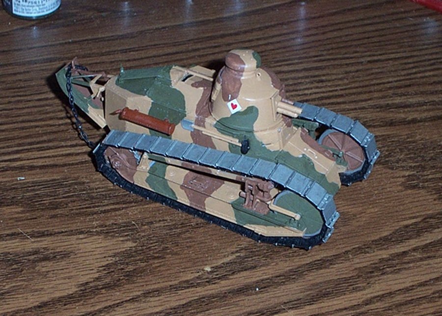
This build was the second build back from a 30 year hiatus from building, (the first was an RPM FT-17 cannon version) I thought as you did that my skills were going to be too rusty for anything but my own edification... What I have really found, is with the patience and wisdom of age, I've actually gotten better.... It's like riding a bike, you never forget and the absolute enthusiasm of youth is moderated with the age..... And the results show it..... Thirty years ago this would not have turned out as well as it did..... (and I still see rome for improvement) My opinion, in this field of endeavour, age is a bonus that adds to the end result.... Over the last couple of months I have learned this, and I personally have no doubts you can do it at least as good as before and much more likely better than you ever have... My first kit in over 30 years...... If I can do that after a 3 decade layover, I'm sure you could too.... Go for it brother, you will not regret it....
-
Thank you Craig, I'm sorta partial to the subject myself, intend to do more artillery and prime movers in the future... (including the little know US Army "88") I lot of great scratchbuilding goes on here in this fora, I hope my contribution added to the overall knowledgebase... Thank you for the compliment it means a lot...
-
Thanks Ken, I don't know about perfect, but it does look the part.... I guess that is what we are after.... Thank you..
-
Thanks Jack, they both are one of those things I wanted to do as a young'un but didn't have the time nor resources.... I hope some of it helps you in rescuing yours.....