


Egilman
-
Posts
4,379 -
Joined
-
Last visited
Content Type
Profiles
Forums
Gallery
Events
Everything posted by Egilman
-
 Thanks Lou, I suspect that if you built one today with the knowledge and experience you have now it would turn out just as well if not better.... I'm happy you enjoyed it....
 -
Thanks Ed, I'm very glad you liked it....
-
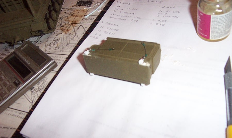
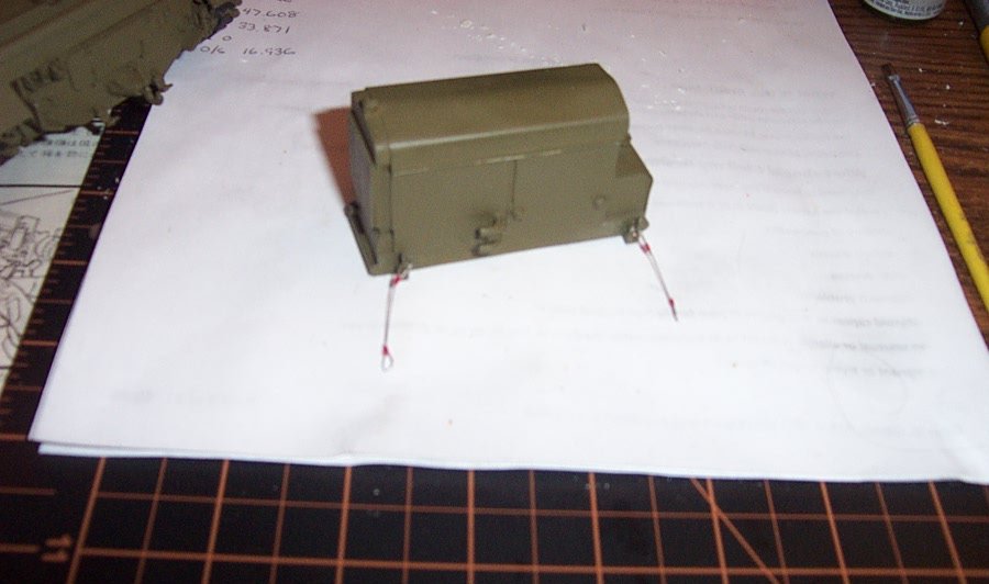
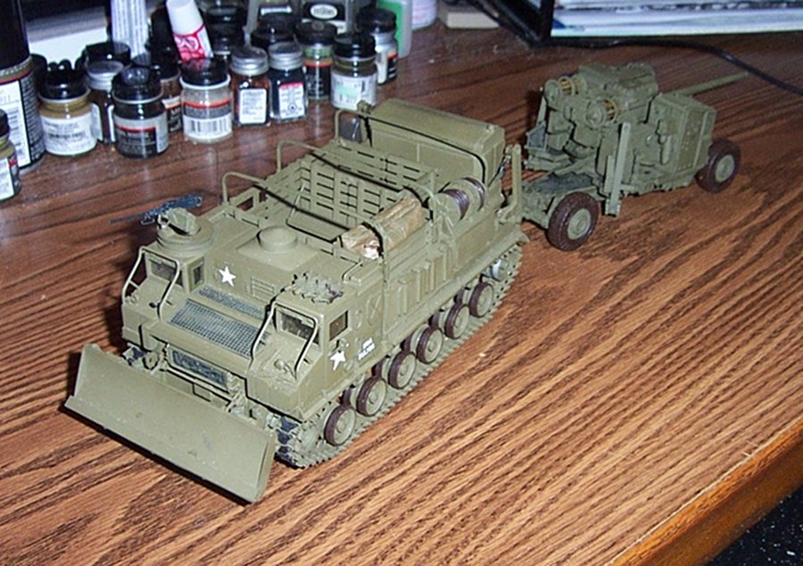
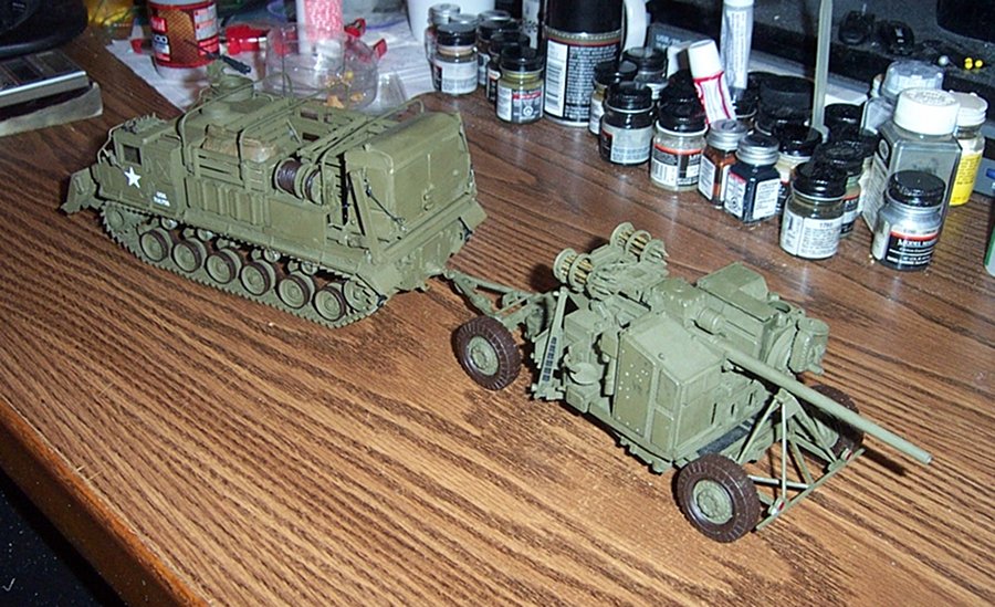
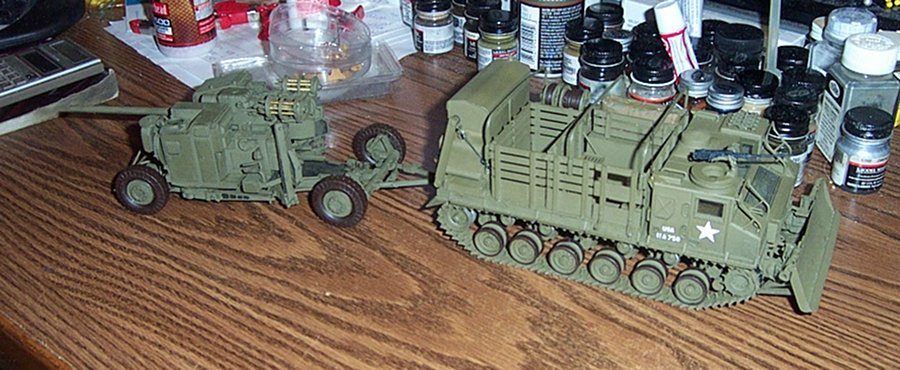
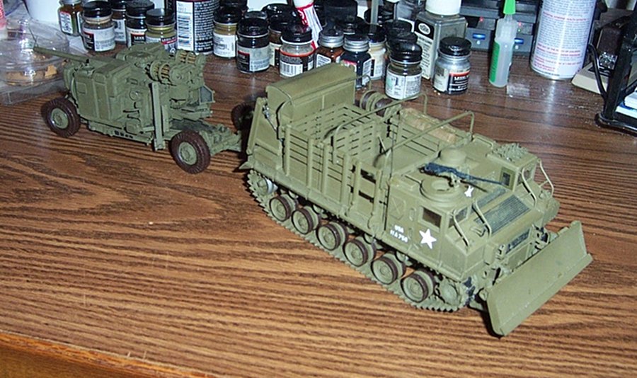
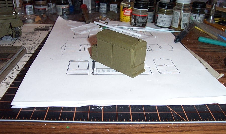
Last construction update..... Finished the Generator and mounted it. Manufacturing the lifting lugs proved to be a bit fiddly but I got it done. Lifting Lugs constructed and attached to the clevises and cables.... Preparing the attachment points.... Putty fills the holes on the ends of the half-round skid bumpers.... Sanded flush and Lugs mounted.... Generator mounted to the lift and raised halfway to full height..... Opposite side view...... Fully loaded position, the fit appears to be perfect.... Painting off the corners and touch ups.... Another test fit.... Cables painted off gunmetal, the Cables, although when manufactured were painted OD Green, in a very short time with moderate usage the paint flaked off leaving the oiled cables exposed. the cables were oiled to prevent corrosion.... Left side profile with the Generator in it's final position and the cables superglued to their lifting hooks....... Left Front view..... Right Rear View...... Right Front View.... Rear view with the generator permanently in place..... (and one touch-up still to do) Mount the drivers door mirror, body hoops and the antenna and she is done.... Complete...... With its M-51 Skysweeper hooked up..... I decided not to load up the body with details, I could have gone another couple of weeks building and adding stuff. This would make an excellent diorama subject not often built... I added a tarp, folded in its storage place above the ready ammo lockers, a simple piece of napkin trimmed to appropriate size, rolled and folded to fit it's space, then drybrushed in field drab with olive drab highlights.... An issue vehicle would have it's tarps... And no the M-51 didn't travel with ammo in the autoloader, it's just that sitting on the shelf for 4 months has caused the rotation mechanism of the ammo holder to freeze up. I couldn't rotate them to remove the shells. So I left it this way cause I didn't want to break it just to take a pic as unloaded..... FINISHED! Thanks for the comments and likes, this was my first major project in a long time and I hope that you enjoyed it.... (even the wife was impressed) EG
- 70 replies
-
- 17
-

-
Thank you Mark Almost finished, thanks everyone for following along....
-
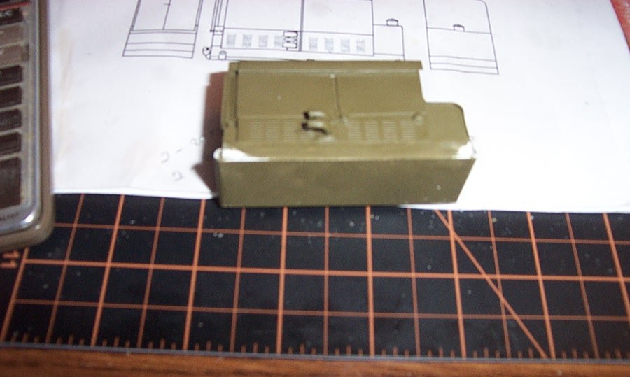
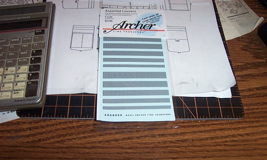
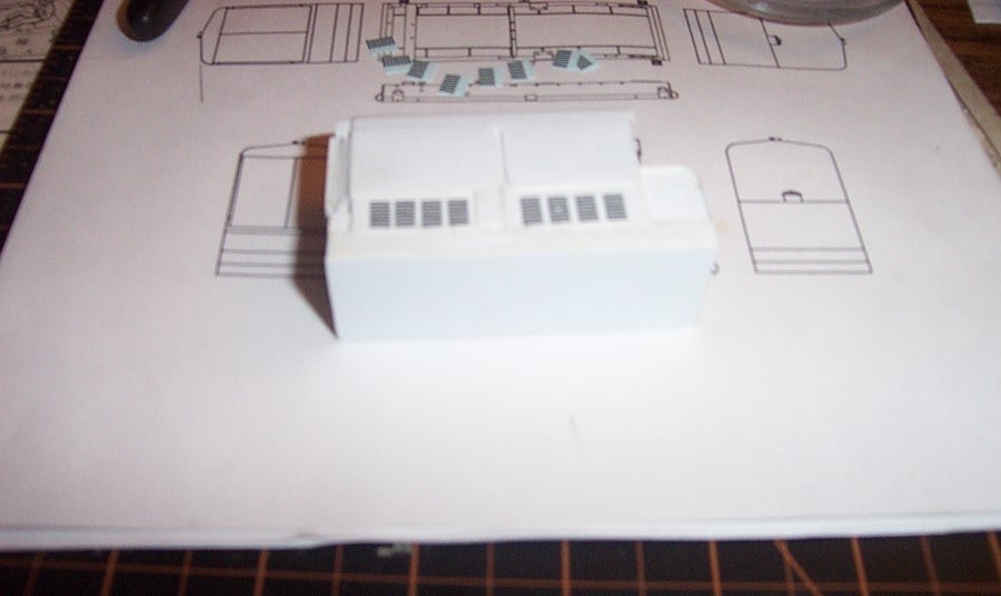
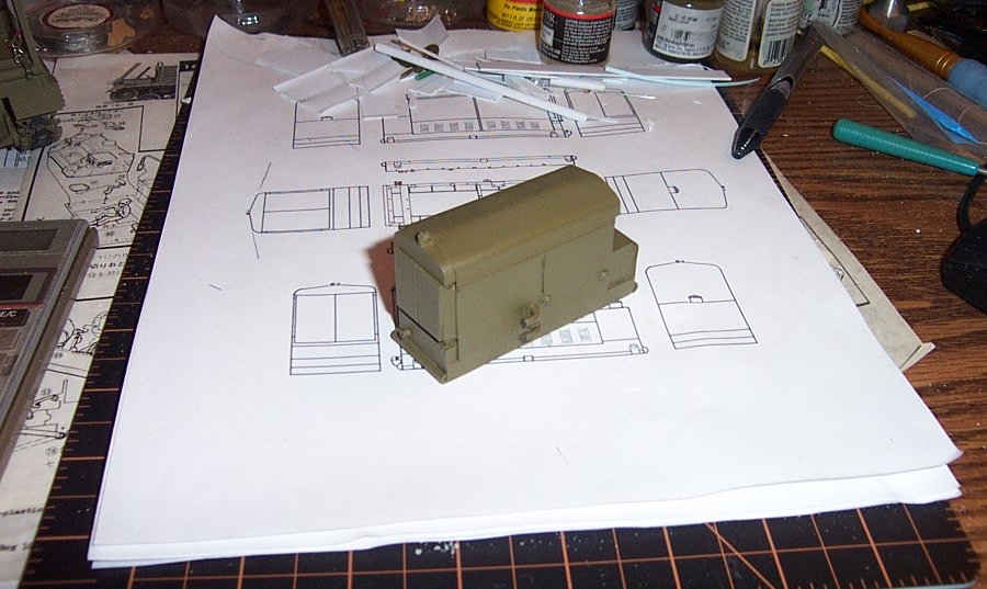
Well we are now going to finish off the M-18 Generator, it's all in the details.... It's pretty much laid out in the pictures above what the details are, most of them are fairly simple and can be reproduced in similie with tidbits from the parts box except the very distinctive louvers, the three power receptacles, the lifting lugs on each corner and the radiused bullnoses on both ends of the frame bottom.... We will start with the Louvers very small and difficult to reproduce. Fortunately, Archer Fine Transfers has come to the rescue..... They make a set of very fine cast resin louvers on decal paper. now these are "O" gauge railroad scale which translates into 1/48th scale for those of us not familiar with rail scale.... Problem is I'm working in 1/35th scale, an oddball metric scale designed to fit plastic models around little electric motors to make build your own toys.... so what we have to do is figure out how long a louver we need and see if something will match the length..... Well my trusty scale calculator told me from my scaled drawings that I needed louvers that were approximately .125 inch long and I would need twelve of them in each of eight vertical columns on both sides of the generator housing.... the vertical column measures .75 inch. In the picture above the shortest louvers on the sheet measure exactly .125 inch and at 1/48th scale that makes a pretty good representation of a 6" louver..... The louvers I need are somewhere between 4-5 inches long so I settled on 4.5 inches long which in 1/35th scale equals .128 inch.... but, in the vertical space allocated for louvers, I cannot fit 12 louvers I can only fit 8.... so we are looking at impression rather than absolute accuracy... the louvers are there and in certain light conditions are very apparent and would be missed by anyone familiar with the equipment.... So, lets see how we did.... This is the left side, sorry it's a little blurry... (they apply and lay down just like decals cut dip in water and when loose, slide into position on a glossy surface, and let dry) The right side in a much better pic.... Now I know they look like black lines, the real effect comes when you paint over them..... Another blurry pic, (I've got to get a better camera) the receptacles mounted on the left side, these are the electrical connections for the gun and director.... This pic of the right side rear shows the frame bullnose, fuel filler and gauge and the radiator cap the hinge detail added above the side doors.... we are now ready for painting...... First coat of paint, left side, given the light angle the louvers are hard to see, they are there but almost invisible.. (which was expected given the color and light conditions) Right side, again the louvers are there, a bit easier to pick out here but still almost invisible... which is what you would see in real life in similar light conditions. Subtle, but effective and very scale appearing in my opinion..... Up on the mount in loaded position the slight light change casts a bit more definition to them. I think they are spot on as far as effect.... but that is just my opinion.... Next up, lifting lugs, mounting to the tractor and finishing off.... EG


- 70 replies
-
- 13
-
-
I thought about that Ken, but I really have never had good results with SG on polystyrene as the primary glue, I can never seem to get it to hold.... what I did was put .020 panels between the formers high enough to lay under the hood/doors giving a large firm gluing area. Then the hood/doors was pulled down over the formers real tight and clamped, letting the tubes hold the shape while the glue set between the flat panels. when it was dry, I put a dab of SG on the peaks of the hood at both ends so the end panels wouldn't shift.... It's remarkably strong.....
-
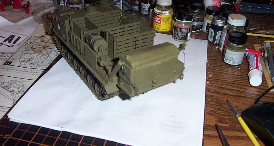
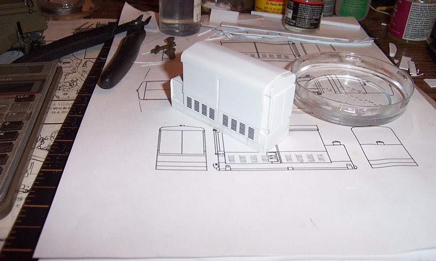
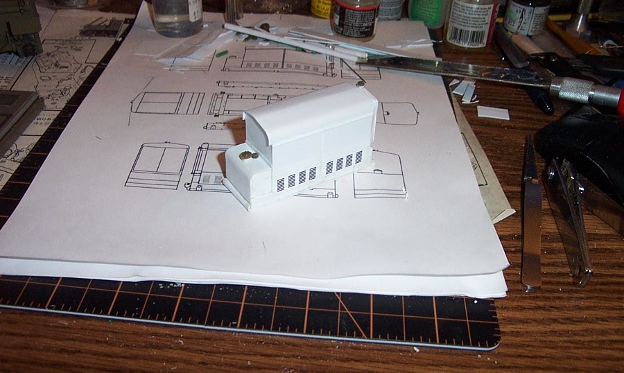
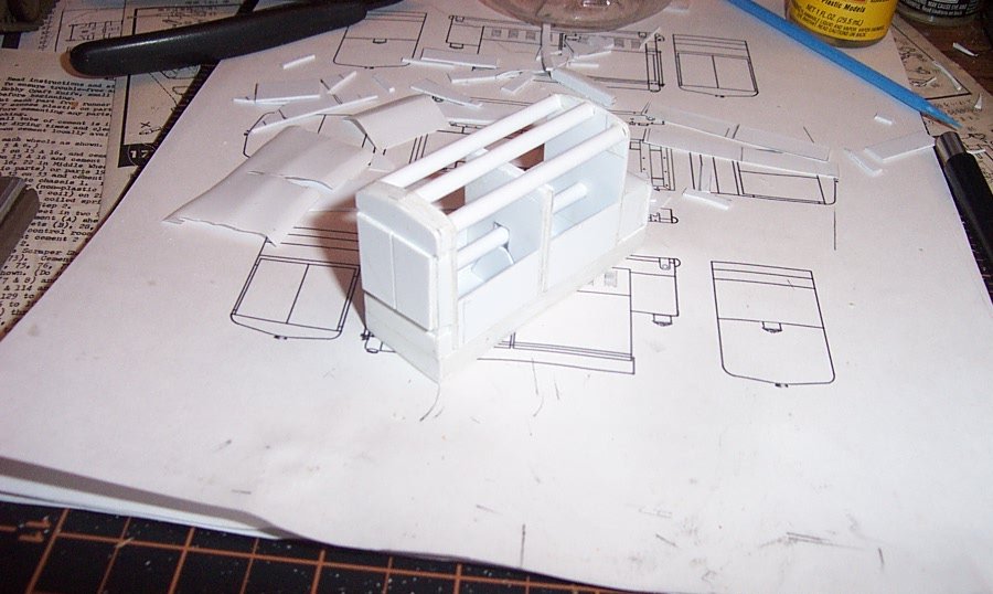
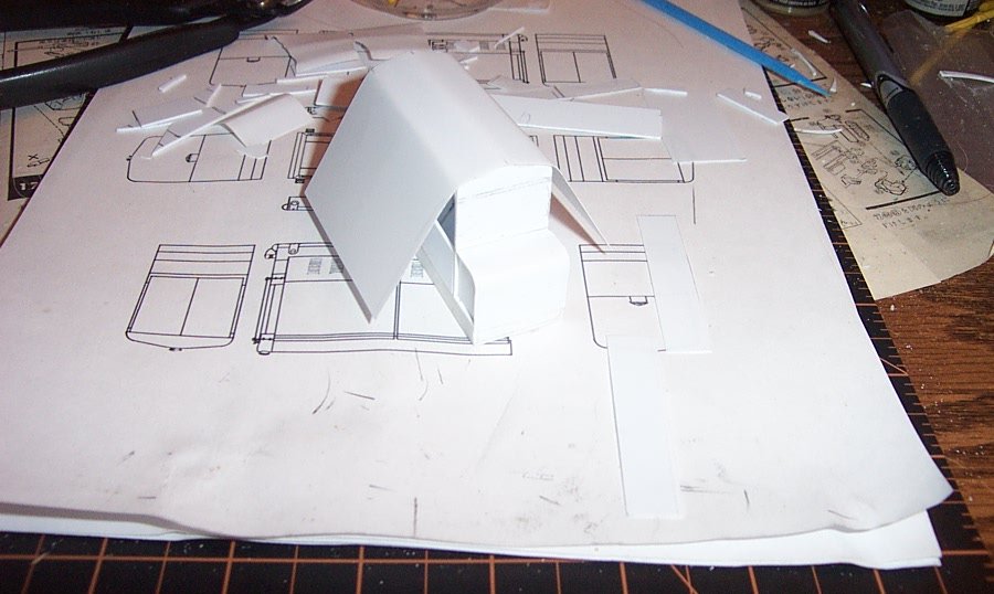
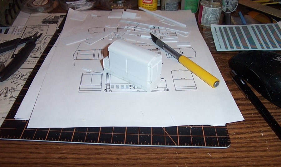
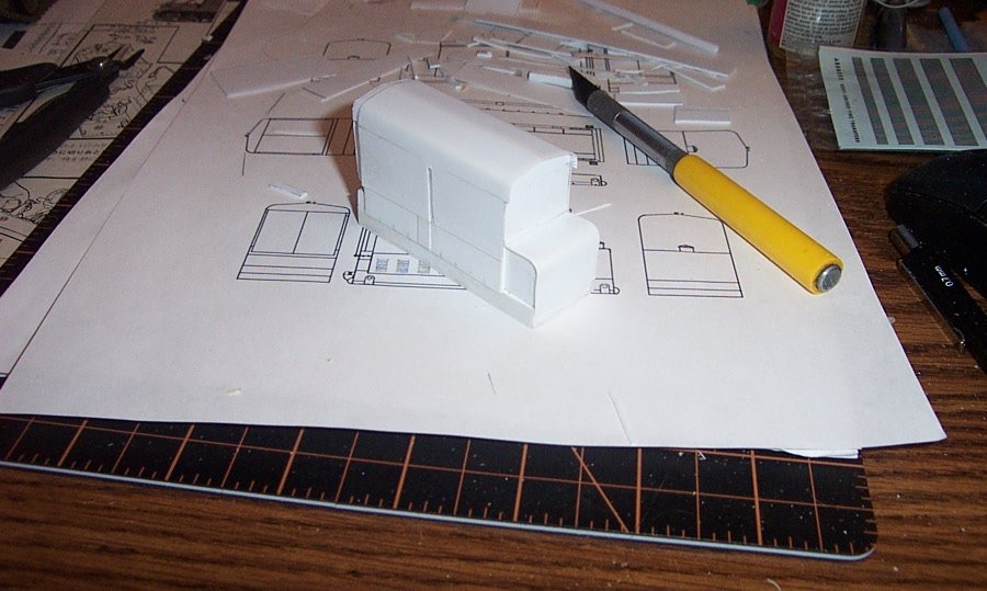
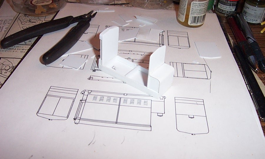
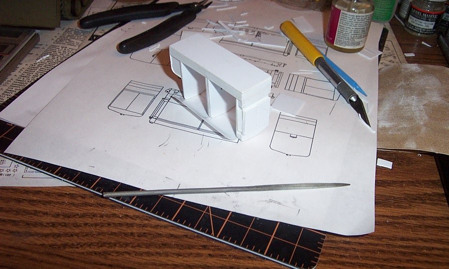
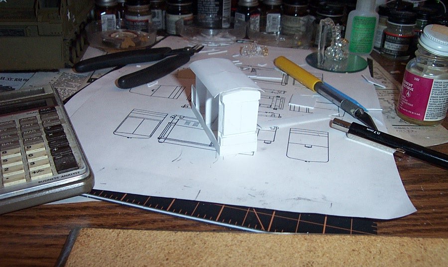
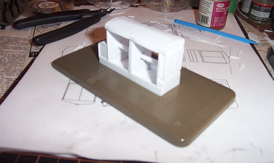
After careful consideration I settled on a way to attach the hood to the frame without the warping and distortion..... The main issue was not enough support from the formers for the thin sheet plastic of the hood. So I cut down the center profile to just below the door hinge line. I then added tubular rods on the three curves, both shoulders and the peak, then sanded the joins smooth. This adds support for the full length of the hood and doesn't need glue except a few tiny drops along the edges..... Below along the frame I added some .040 plastic sheet to reinforce the center support and give thicker plastic where the side panels and doors would wind up, a solid gluing surface..... Lets see how it turned out...... Back to square one, figuring a new way to mount the hood. I need to use .010 for the hood as it gives the proper scale appearance, but have to figure a way to edge glue it without depending on the formers to shape it. Beefed up frame.... Hood and side doors prebent. I lengthened the hood to incorporate the side doors into one piece, this allowed the side doors to keep the outer edges of the hood from bowing outwards. Since the hood and doors lay on the same plane in real life this is the elegant solution for the plastic tension that was causing the hood to warp.... Hood and Doors folded along the shoulder line, I'm using my container of paint stirrers to provide the weight needed for the plastic to stay in shape and settle into it's folds without creasing the corner.... The folded hood ready for installation..... The hood installed and the door separation groove cut to just below the hinge line. Right front view, completely glued and no distortions/warping.... Left Rear view, you can clearly see the hood end overhang without any deformation or warping.... Since we now have the M-18's basic shape complete it's time for its first test of fit sitting in its position on the rear platform of the M-8 HST..... And the opposite right rear view showing it appears in scale and fits in its spot comfortably... Now, continuing on to the details...... EG
-
That cause we all knew that the sharp edge went forward so it cleanly cut thru the air.... (even that young we understood that the pointy end goes forward)
-
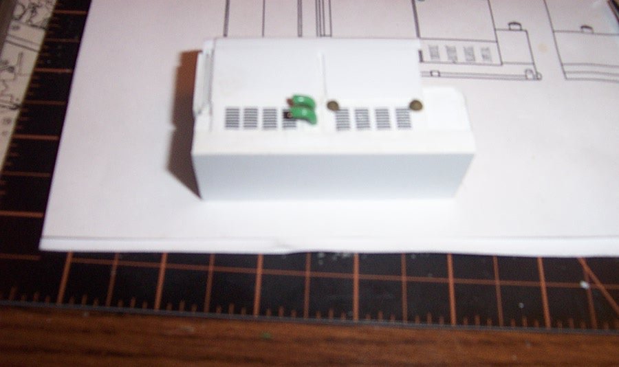
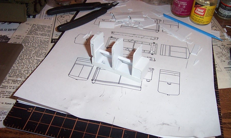
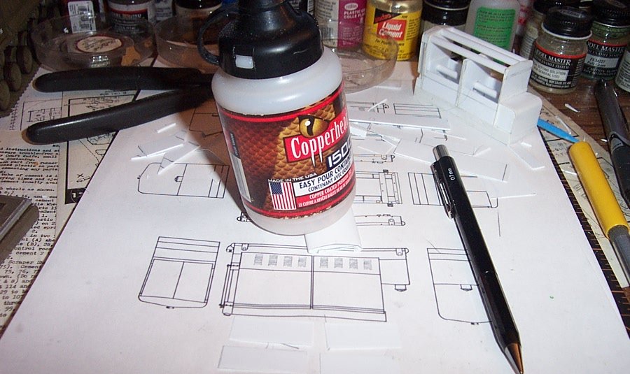
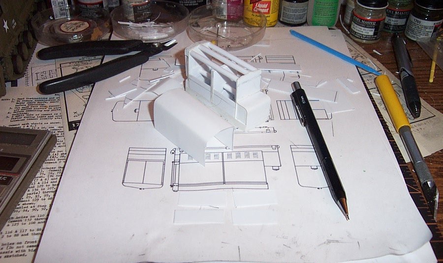
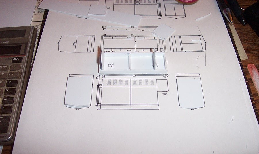
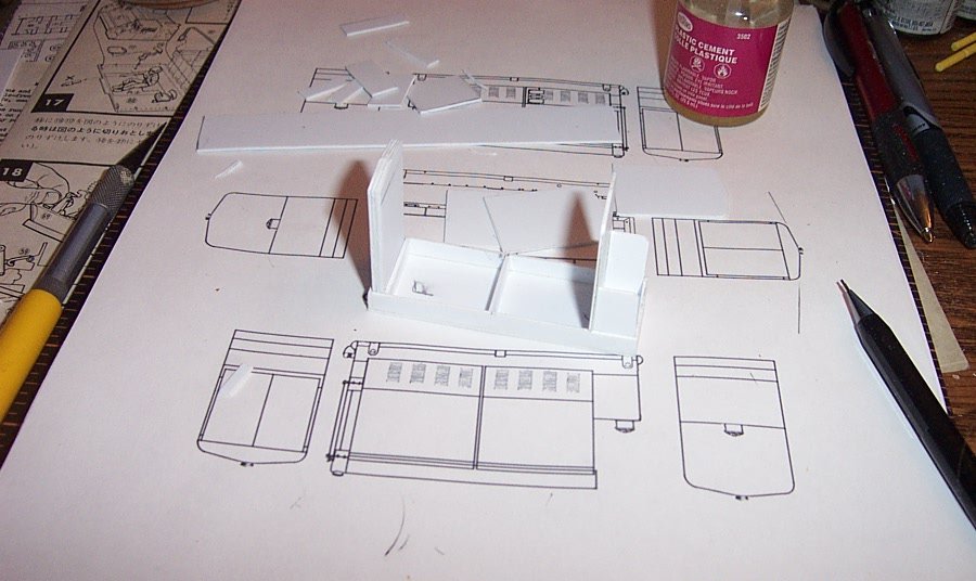
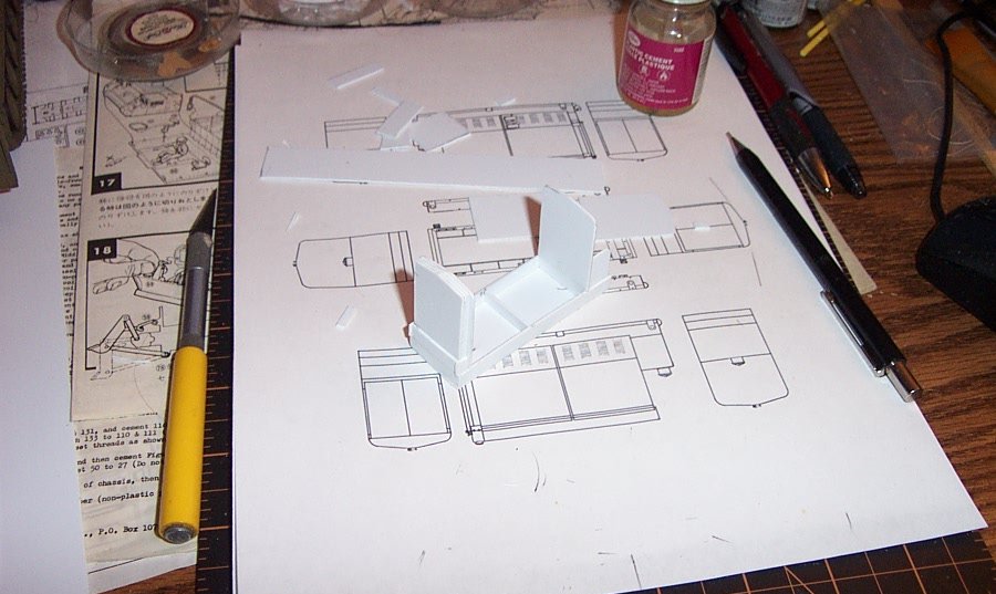
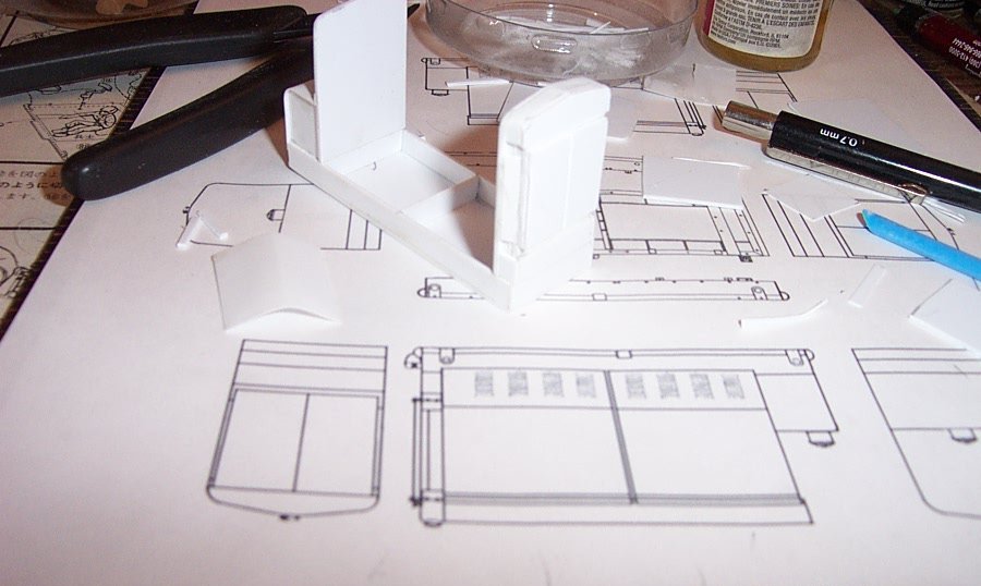
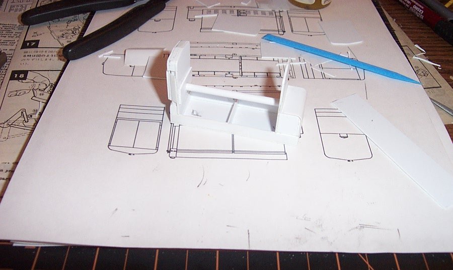
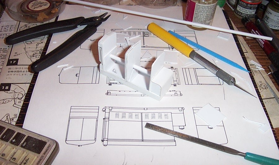
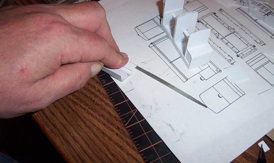
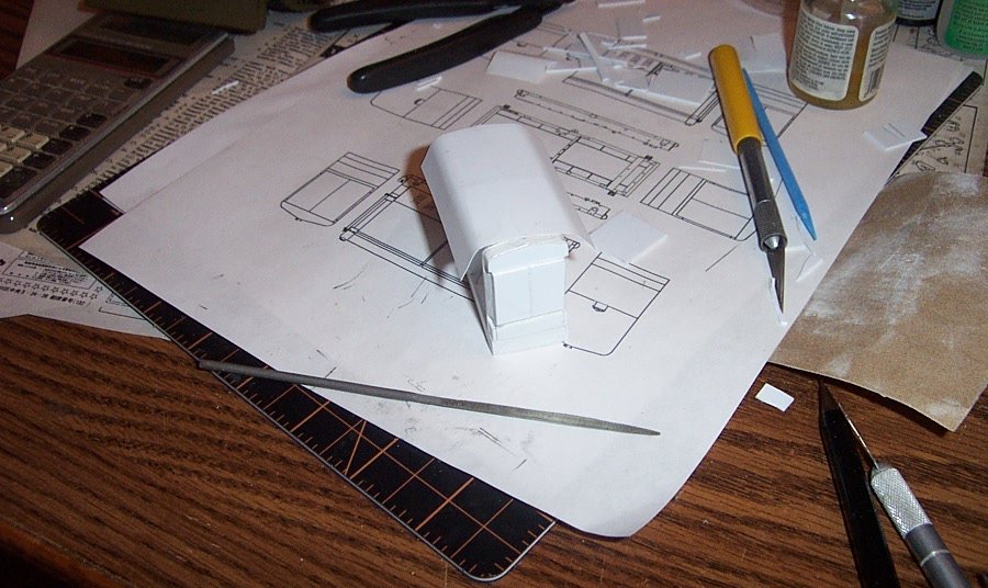
As mentioned before I was able to obtain the US Army Tech Manuals for this particular piece of equipment, it is a 35Kw continuous duty alternating current generator. Usually it was supplied to the antiaircraft units using the 90 & 120 mm antiaircraft guns during WWII/Korea and postwar to the M-51 Skysweeper battalions. Capable of supplying the power requirements of an entire battery of guns, (4) including their directors. Additional units were supplied to support the radar companies that were attached to the AA battalions. Little known fact, all of our heavy antiaircraft weaponry from about mid 1942 on, has been power laid and radar guided, accompanied by the VX fuse, they became the deadliest AA guns the world had ever seen. This was the power unit that made it all happen for the US Army. This is my attempt to recreate in 1/35th scale one of these absolutely essential pieces of equipment. Time to hack some plastic...... Basic box parts used as a frame. the original frame was built of steel channel and plate, for this a simple box will do. Base glued up, I'm using .040 sheet styrene to make the foundations and basic profile shapes. Tabs added as stiffeners and locators for the interior bulkheads Rough cut radiator in place along with the end bulkhead and sidewalls for the fuel tank compartment. Forward bulkhead glued behind the radiator, core support sections added around the base of the radiator, two more bulkheads in the middle to support the side panels to go. Fuel Tank cover in place cut from .010 sheet.... Radiator built up with doors and side supports out of .020 sheet.... Once the radiator was added the whole thing started to develop a narrowing towards the top, so I added a strut to push the top opening wider and back into vertical alignment. Center support build up out of .020, this is needed cause the side panels are split fore and aft forming the two access doors and side covers. Forming the hood out of .010 sheet. (wrapping it around a file handle to set the curve) Hood glued on the left side. Gluing the right side of the hood around the profiles. Beginning to take shape, but note the wrinkle that has developed in the middle of the hood. Sorry for the blurry pic. But even such, you can easily see that with the right edge glued down around the side curve, a major issue shows up here, the glue (MEK) is too strong for the .010 sheet styrene and has caused warping and deformation of the sheet on the ends. Also note the edges of the hood over the openings, the tension in the sheet has caused the hood to bow outwards. This isn't going to work. I need to support the hood on the ends and middle where it contacts the formers also over the openings so it doesn't warp....... I need to rethink how I'm going to form the hood..... It needs support all along the top edge and an alternative way of gluing it down so the glue doesn't destroy the edges..... Next up, the solution...... EG
-
WE all have our glue smeared messes in our backgrounds.... part and parcel of learning the art... just like not being able to color between the lines in kindergarten.... the more you try, the better you get..... Michaelangeo didn't carve "David" his first time out..... Thank you for the comment....
-
1931 Cadillac by CDW - FINISHED - JoHan - 1:25 Scale - PLASTIC
Egilman replied to CDW's topic in Non-ship/categorised builds
Yes, the extant case was in baltimore where a 7 yr old ws suspended for chewing his poptart into a gun shape and was suspended on the school districts "zero" tolerance for guns policy.... shortly afterwards a child ws bounced here in washington and in florida for the exact same thing citing the same policy... Later the courts, on appeal upheld the suspension which is now permanently on the boys school record.... Here in Washington it is ok for an elementary child to carry a 6-9" ceremonial dagger in school as a religious object (sikh religious artifact) but can't point his finger and go "Bang Bang" https://2ahawaii.com/index.php?topic=16905.0 (unfortunately the links to the original media story are dead) -
1931 Cadillac by CDW - FINISHED - JoHan - 1:25 Scale - PLASTIC
Egilman replied to CDW's topic in Non-ship/categorised builds
Yeah, it's gotten to the point if you take bites into your poptart in the wrong places and sequence in the school lunchroom, you can be booted out of school for firearms violations..... (at least in certain school districts here in Washington State...... (true story) -
That was one of the first things President Reagan did, start the process of upgrading all the almost worn out WWII/Korean war equipment that the military was making due with...... it's one of the things you CAN credit Bill Clinton with is that he continued the process.....
-
They built a lot of M-18's they were used throughout the '60's well into the '70's before they were replaced....... They remained substitute standard into the '90's....
-
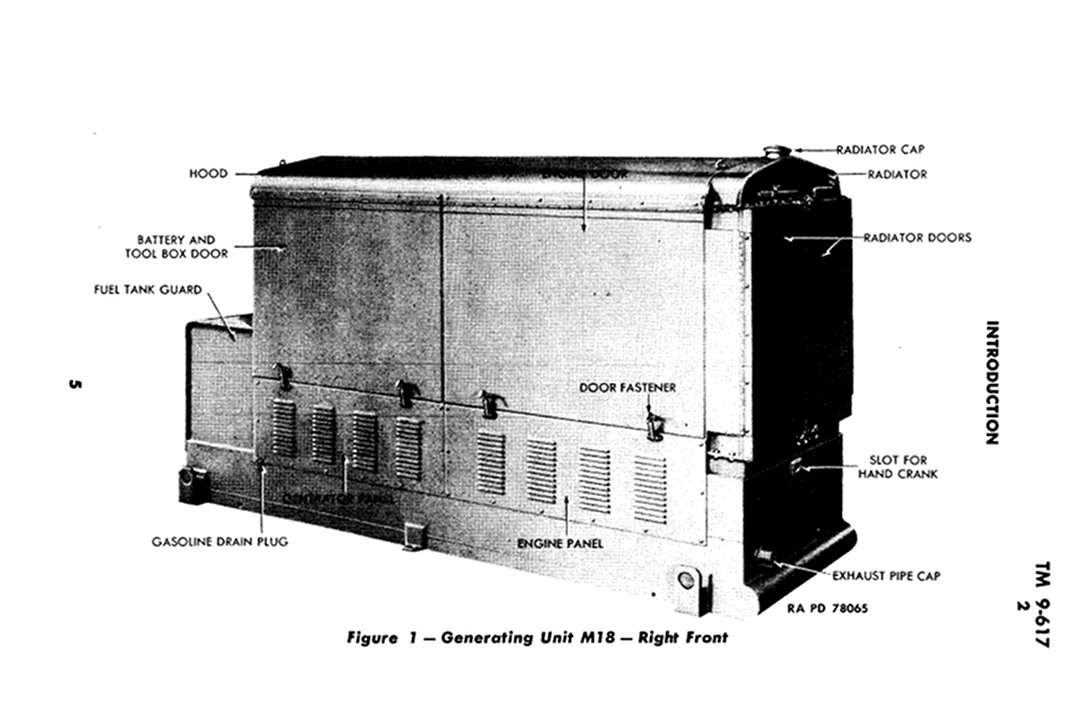
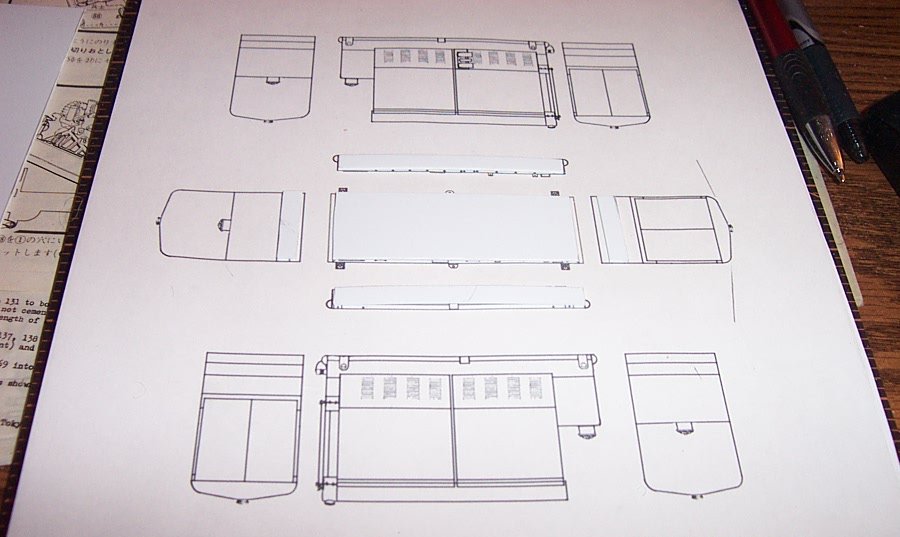
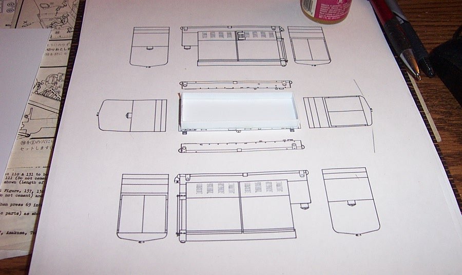
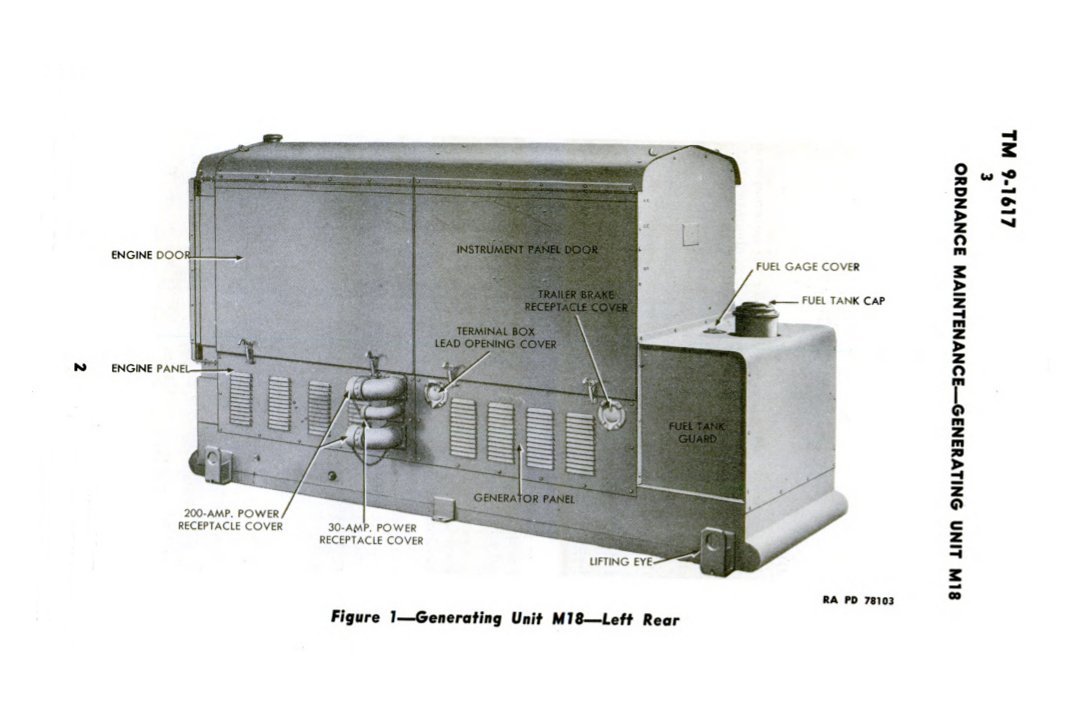
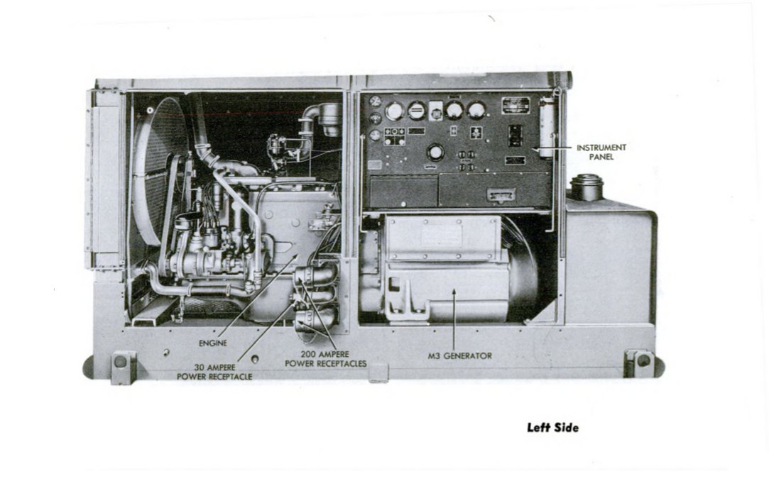
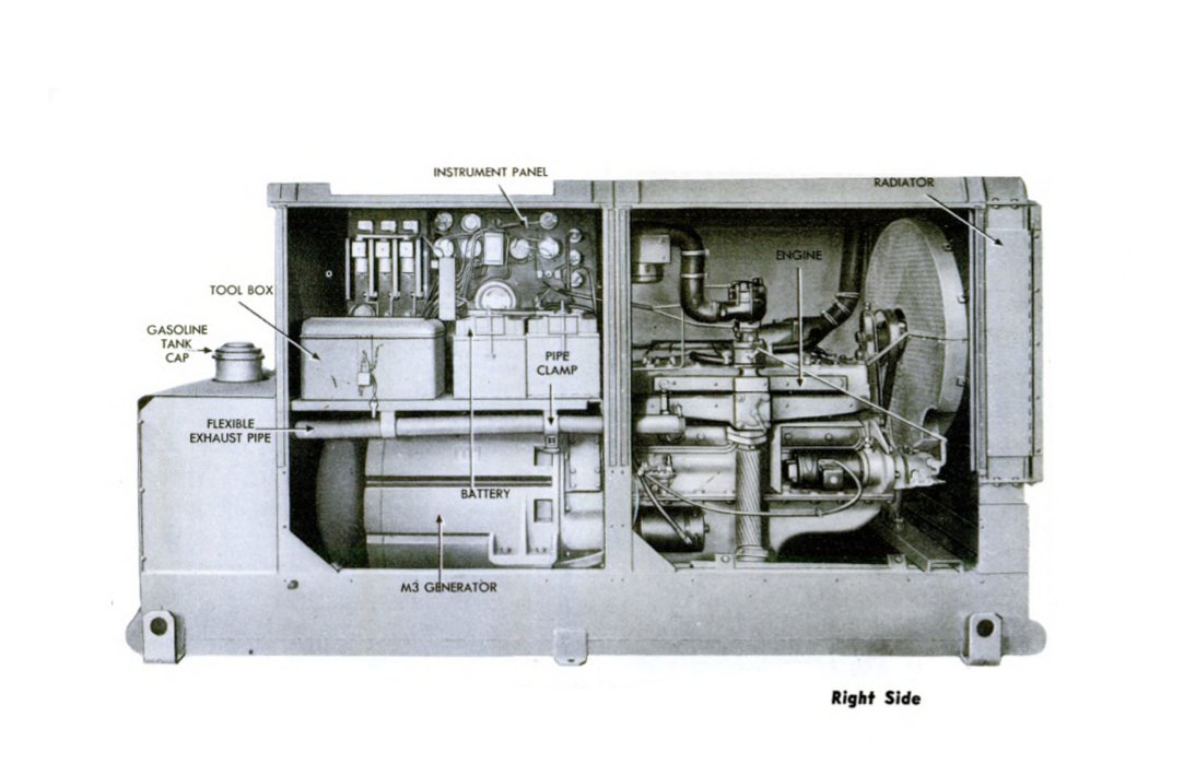
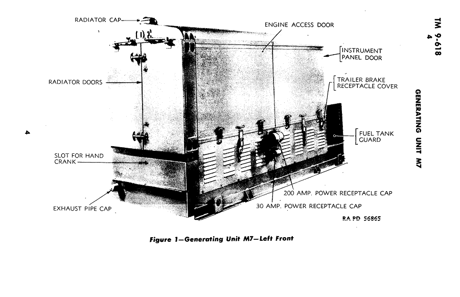
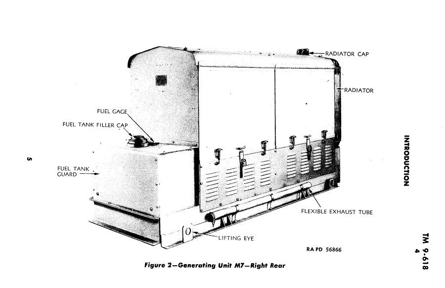
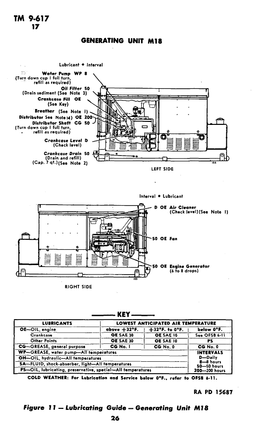
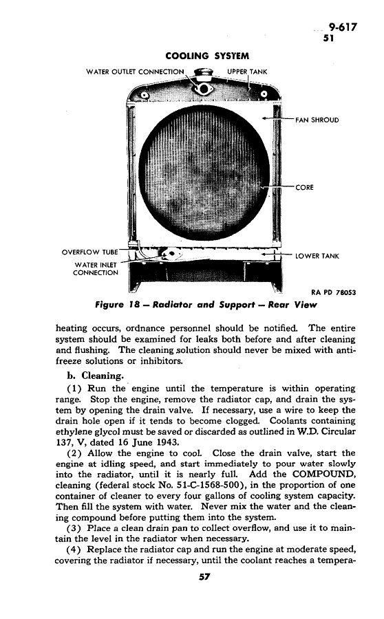
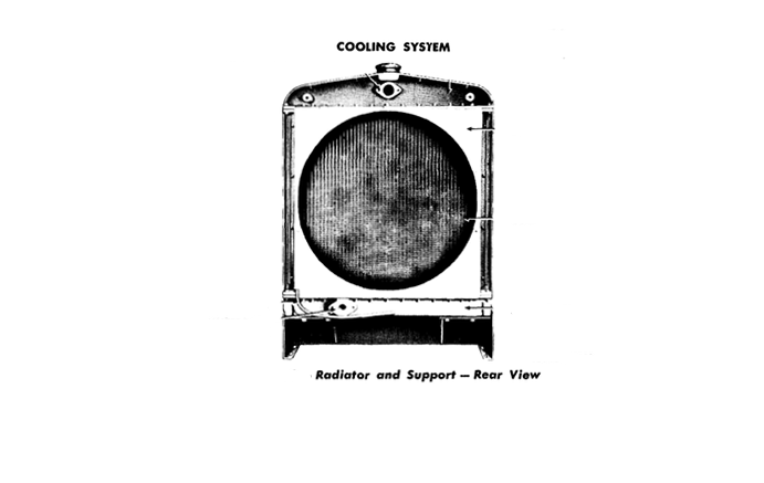
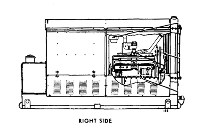
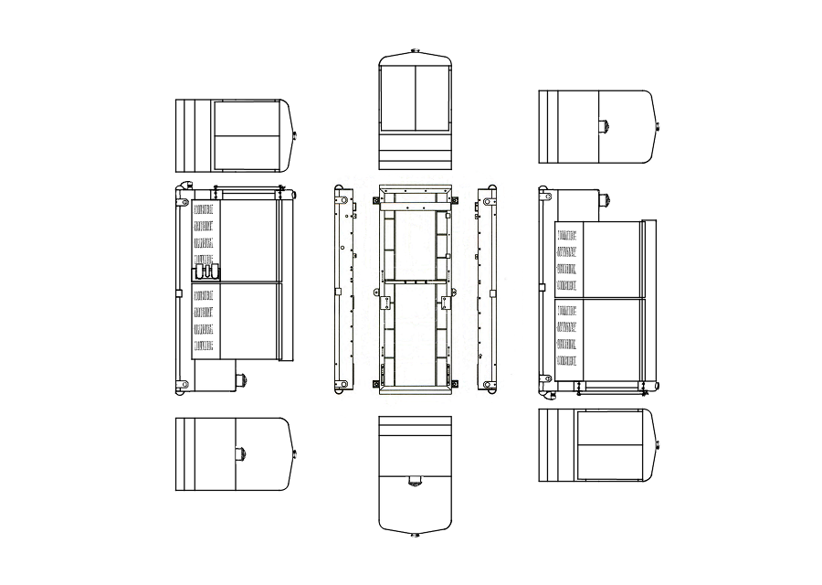
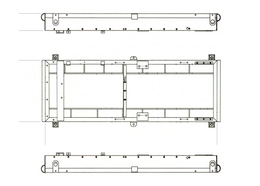
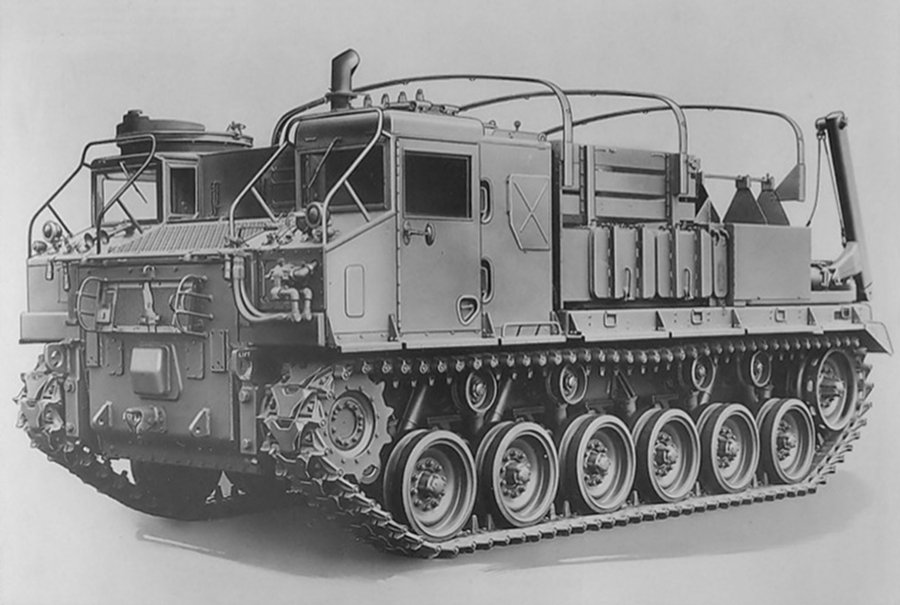
Well it's time to start the process of accurately modeling an M-18 Generator... first step gathering images, overall images and detail images.... All scale scratch building starts with preparation..... This is what I need to create, it measures Length, over-all ................................... 100 1/2 in. in 1/35th Scale ...... 2.87 in. Width, over-all ..................................... 41 5/8 in. ...... 1.189 in. Height, over-all .................................... 56 5/8 in. ...... 1.618 in. First thing to do is get an accurate profile so I will need two sides and a vertical.... The images above I've posted before they definitely give an indication of the details required and come from the US Army Tech manuals for the unit.... These two images come from the US Army Tech manual for the M-7 Generator set, the M-7 is just an earlier model of the same capacity and size just not s refined.... It's good to get a design history so one can see what the engineering principles were for the particular piece of equipment. These two generators were used interchangeably during WWII, but the M-7 was phased out by the Korean War in favor of the M-18. Although good for details, these images do not give me what I really need, which is profile drawings/images..... for that we have to turn to the operator's manual TM 9-617.... Page 26 and 51 of the operator's manual gives exactly what is needed, direct face on profiles.... The first step we need to do is clean, correct their sizes and scale them... For example look at the radiator and core support image above, it is stretched vertically.... the fan opening need to be a circle.....Ve I prefer to use gimp for image processing, the vertical profile is now corrected and scaled as well. It was squeezed narrower that it really was. This was easy to fix in Gimp by scaling it out wider till the fan opening in the shroud was a true circle.... M-18 left & right side cleaned, cropped and scaled. The fan shroud pic above also has the radiator core support so it was an easy job to scale it to size matching it to the left profile in height from the core support up to the radiator cap, this also gives you an accurate width once the vertical stretch was removed. Frame image cleaned and scaled. Once all this is done we can assemble and print out a scaled construction guide...... This image shows all necessary views needed to build a scaled replica..... Next part, cutting plastic.....


-
1931 Cadillac by CDW - FINISHED - JoHan - 1:25 Scale - PLASTIC
Egilman replied to CDW's topic in Non-ship/categorised builds
You never know with the Department of Homeland Security nowadays...... -
1931 Cadillac by CDW - FINISHED - JoHan - 1:25 Scale - PLASTIC
Egilman replied to CDW's topic in Non-ship/categorised builds
There are quite a few cleaners that when mixed together cause spectacular reactions.... Baking soda, (an alkli salt compound) and vinegar (an acid compound) for example. They both work very well as cleaners and are usually found in every housewifes kitchen cupboard..... combine them and they can be explosive.... Concentrated Hydrogen Peroxide is another, they used it to put men on the moon..... (driving the turbo pumps of the Saturn V's F-1 engines for example) One must be very careful when mixing common household cleaning materials or other common, normally safe, materials.... -
Amen brother.... life can be hell at times....
-
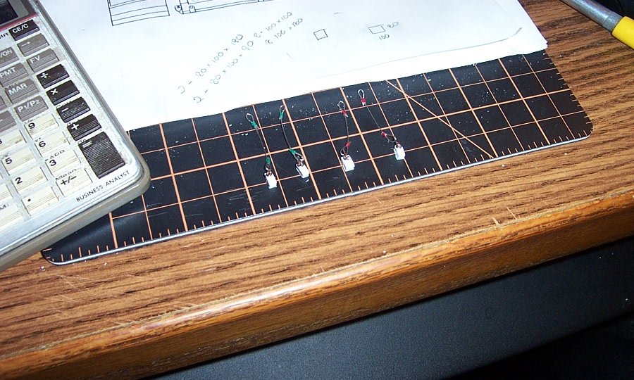
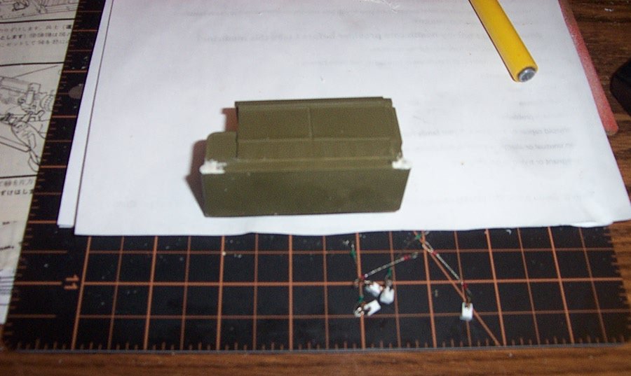
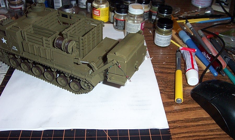
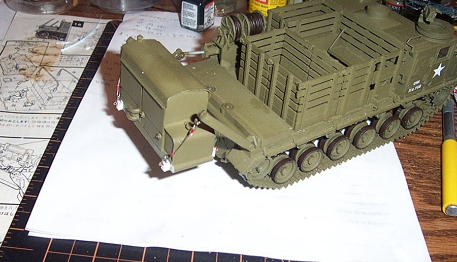
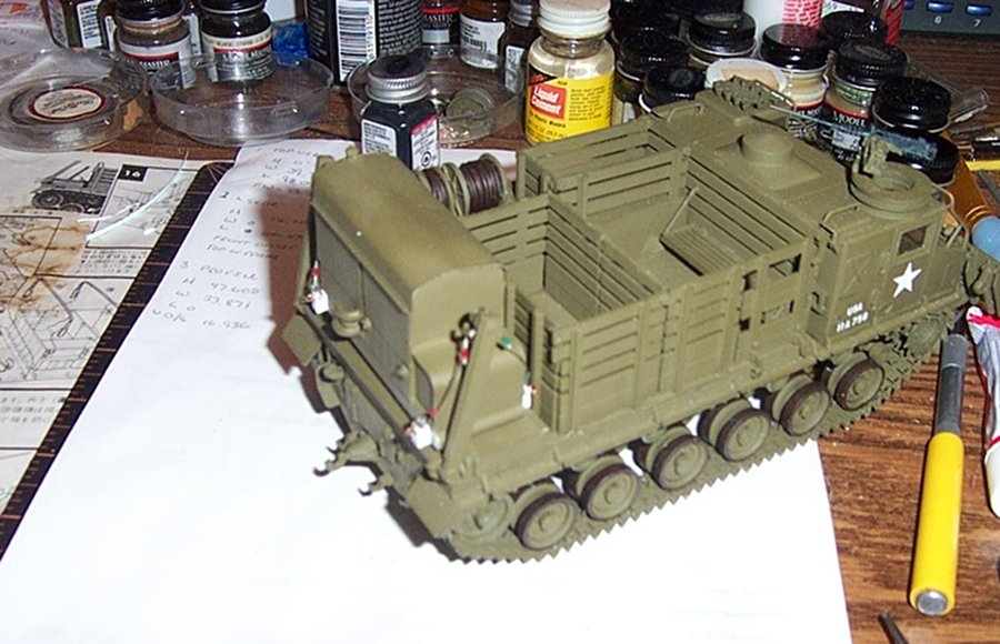
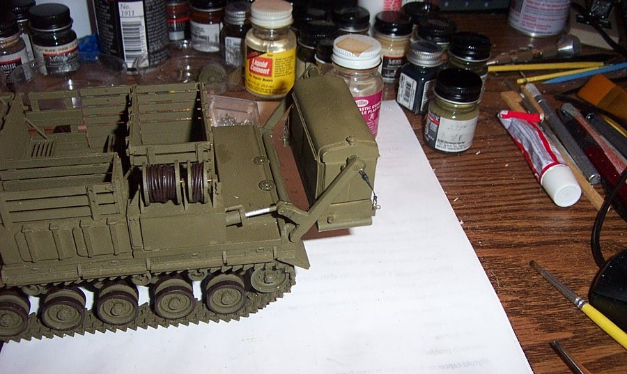
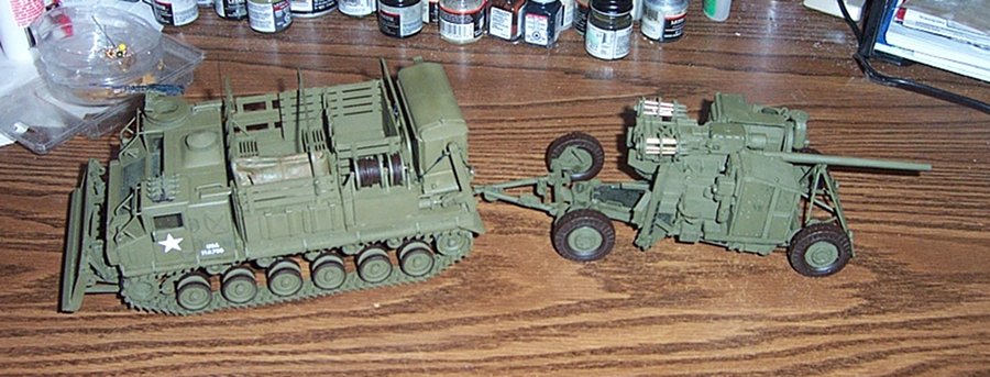
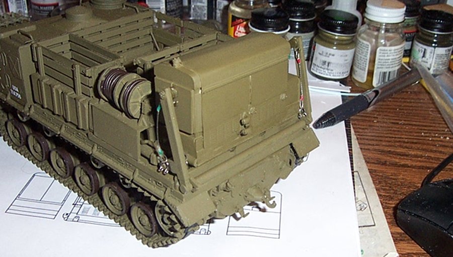
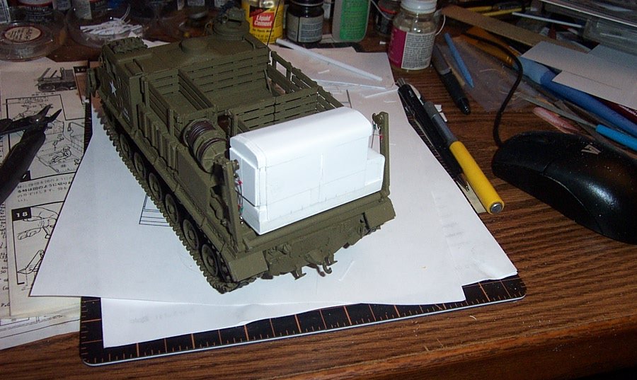
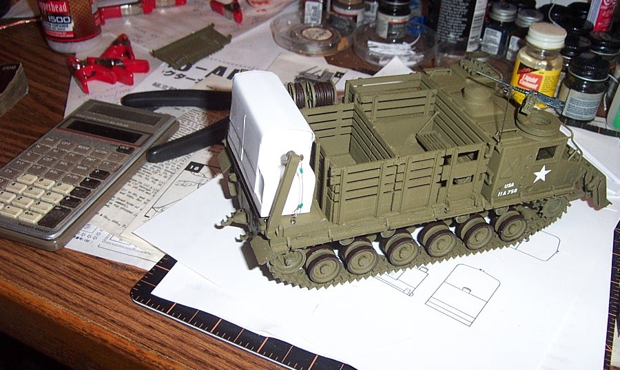
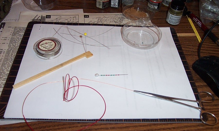
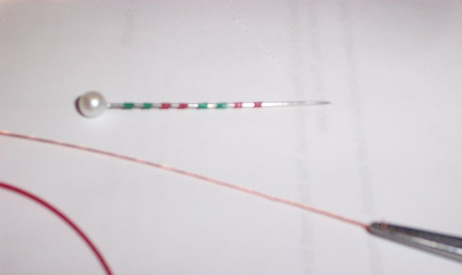
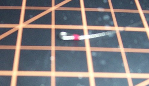
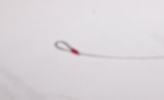
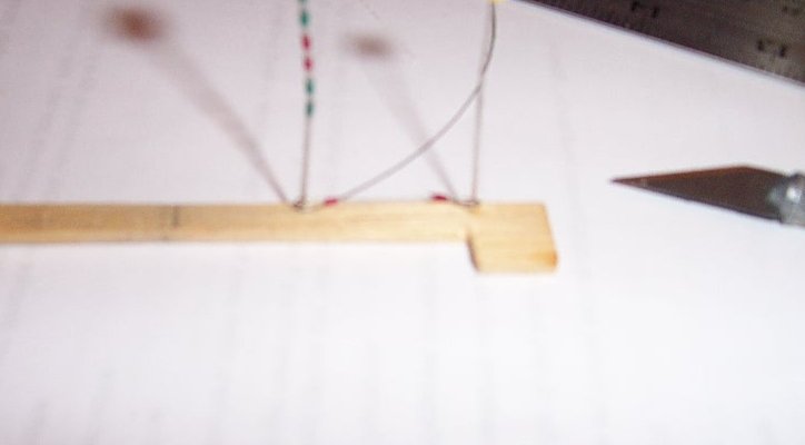
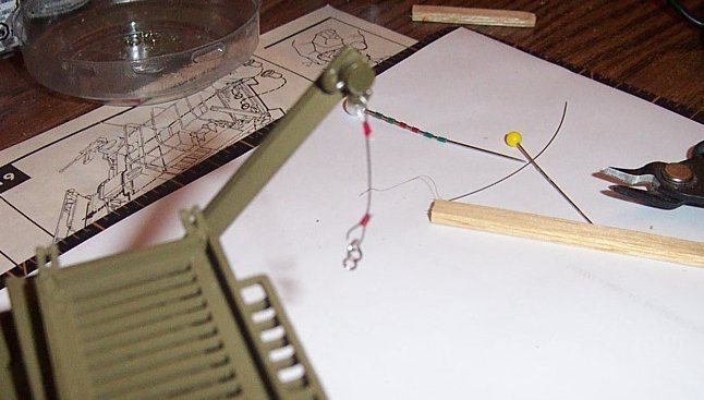
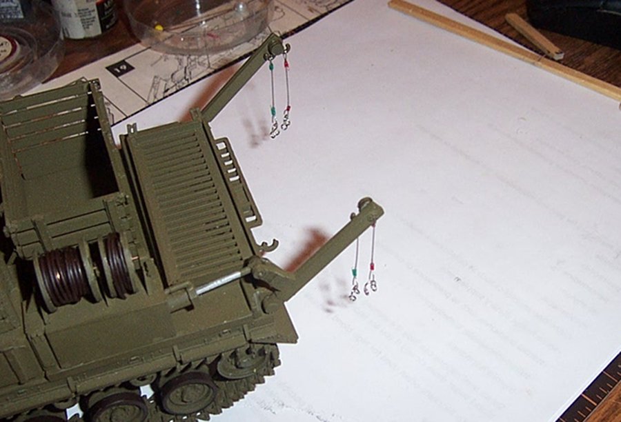
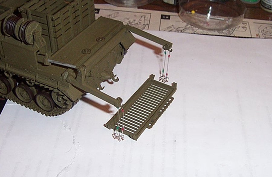
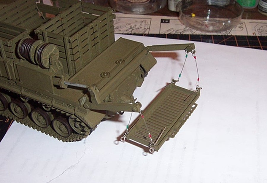
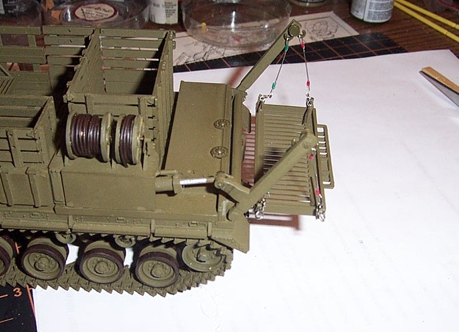
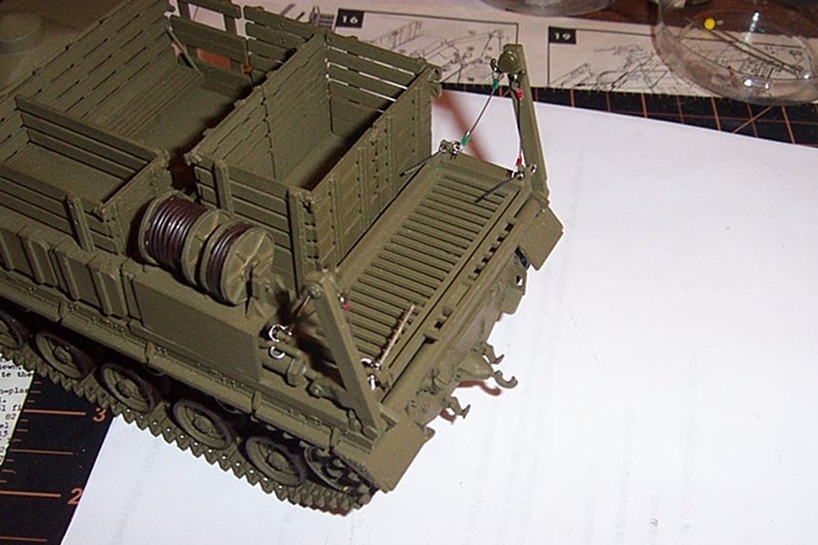
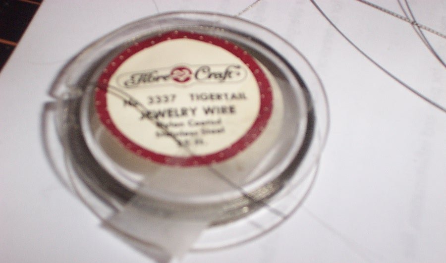
Ok, now for scratch building the Skid lift loadout. The original issue equipment for the M8A1 HST was a 30 Kw generator set that was designated the M-18. It was loaded using the 3 ton hydraulic skid lift mounted into the rear deck of the T-48 Skysweeper body by attaching four cable straps to the four corners of the load and the double swivel hooks on the lifts arms... (see previous images as to configuration of the lift) the operation was by hydraulic ram attached to the left side arm, pivoting on a torque tube to the right side arm that was attached parallel to the left arm. Extension and retraction of the ram caused the arms to move outwards rotating around the torque tube to move the load rearwards off the deck and onto the ground for unloading, Loading was the opposite. A very simple system the load didn't even need to be tied down as while on the tractor the lift cables were never detached.... First thing we need to do is build the lifting cables.... For this I'm using .015 jewelry wire known as Tiger Tail wire which is a stainless steel four strand twisted wire which looks the part very well... I'm also using 2mm pieces of the insulation from twisted pair telephone wire to simulate the ferrules used to close the loops on each end.... Beginning my attempt to dress out the pallet lift.... The materials.... Almost looks like we are going to tie flies.... in the upper center you see the pieces of tiger tail wire for the cables and pushed onto the pin in the center, you can see the eight pieces of insulating jacket being used for the ferrules... (just a note: my camera does not take very tight close ups very well, so many of the pics are going to be blurry, but you should be able to get the concept of what I'm doing from them, my apologies, and I will try to describe what is going on in detail to make the process clear Feel free to ask any questions that might arise) 2mm long pieces of phone line insulation, what you see here is the pieces being stretched to twice their normal size using the dressmakers pin as a mandrel this is to expand them so you can put two wires through to close the loops. Once pulled off they will slowly shrink back to their normal size. They have been on that pin for 36 hours they should have some memory, but I will still have to work fast before they shrink down to normal size.... This is a simple process, slip a insulation piece onto the wire and reinsert the wire end into the insulation piece forming a loop, pull the loop down to about 1/8th inch long and put a drop of superglue on the insulation. Then trim off the excess wire... The instructions said to make them 24mm long, but this is for the kit part representing the load skid. On the part, the connection are on the ends and are raised above the skid, on the generator, the lifting lugs are on the sides, this necessitated making them a bit longer to compensate for the different location of the attachment point.... I went with 26mm so I pinned the first loop on a piece of balsa and placed a second pin 26mm away for forming the other end loop. You arrive here by slipping a second piece of insulation onto the wire and letting it slide to the middle, form the loop the same as last time by feeding the wire back through the insulation piece, then place the pin through the loop into the balsa and push the insulation to the pin. then pull the loose end of the wire through the insulation piece until you arrive at a similar sized loop as the other end with the top of the loops tight to the pins. Then using a drop of superglue, affix the wire and insulation piece. I use instant superglue for this cause as soon as you let go the wire shifts in the insulation losing the length. once dry remove and clip off the excess wire.... The first completed cable hanging off the lift boom, at the bottom end is a single bra clasp loop with the ends rotated 90 degrees to form a decent looking clevis... (even if it is a bit overscale, it looks the part) All four of them completed and hanging from the lift arms, now to test them..... In the loading position.... Using jewelry pins as temporary clevis pins....... (and the load is suspended just off the deck) Half way up and it appears that the load will clear the deck, the one cable in the back appears to be a mm long..... Fully loaded position, and it looks like the images of the actual cables I have... I would say success... Now these get set aside, (after adjusting the long cable) to wait for the generator... coming up, building a US Army M-18 Generator...... EG
- 70 replies
-
- 12
-
-
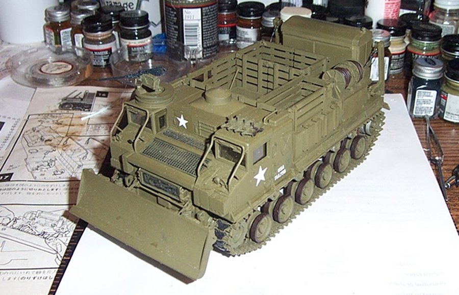
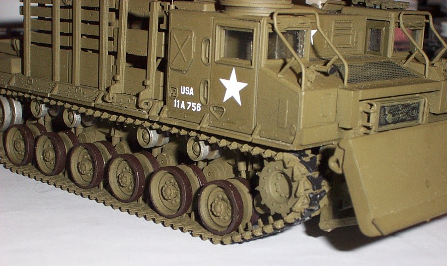
Alcohol on the cleaning, only thing that works with half a chance to not remove the paint... The color is Model Masters rattle can Olive Drab.... It goes on nice and has the proper light effects. brownish green under yellow light and dull green under grey/white light it acts like real olive drab paint should. I've never had a bad result with it... (and the bottle paint is an almost exact match) It's the only olive drab I use.... The tracks look the part, they are in scale, pivot on the correct points, and you can represent them either with or without the road pads, you couldn't ask for a better representation of the real tracks for this kit... And once your done, post a repair/rebuild log.... Seems like there is lots of interest here...... I hope this helped.... And thank you for the compliment... EG
-
I have some #35 spider line also, but it looked more like a weave to me rather than a twisted cable.... (I use it to simulate 3/4" woven poly rope) I had another option also, Twisted pair, Telephone extension line from the old hardwired phone days.... made from fine drawn copper, once stripped of it's insulation and twisted tighter, it does a good job at resembling cabling in scale also.... I've used all three in the past when I've needed to represent rope with real strength.... (they all work well for what we do)
-
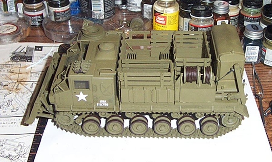
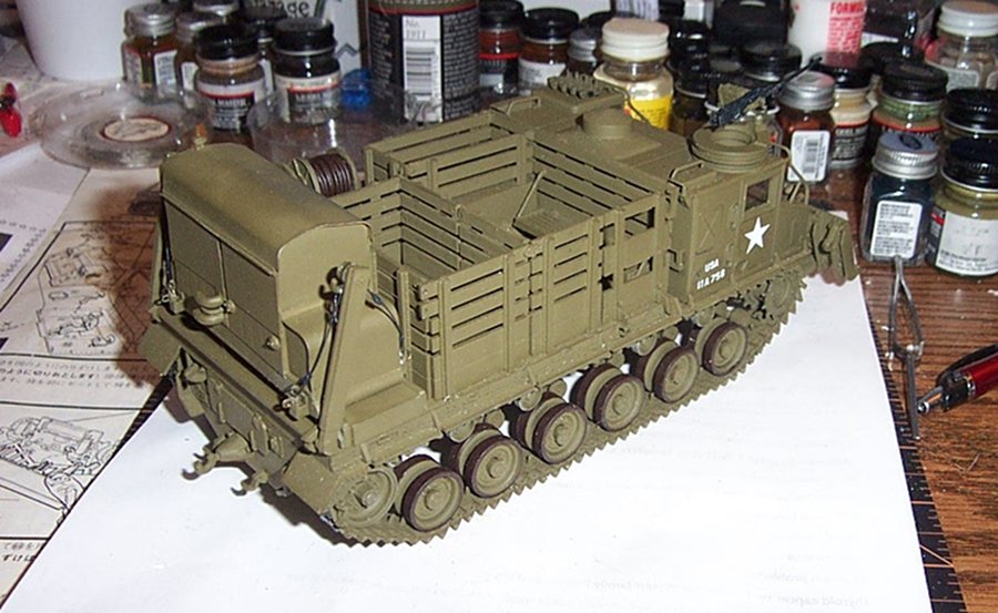
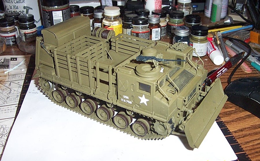
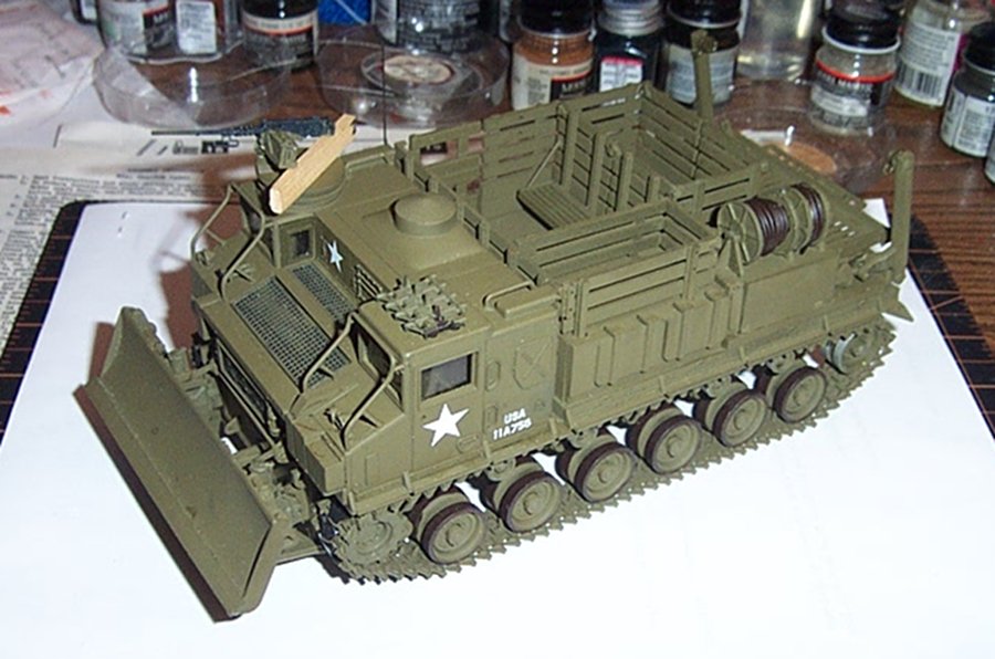
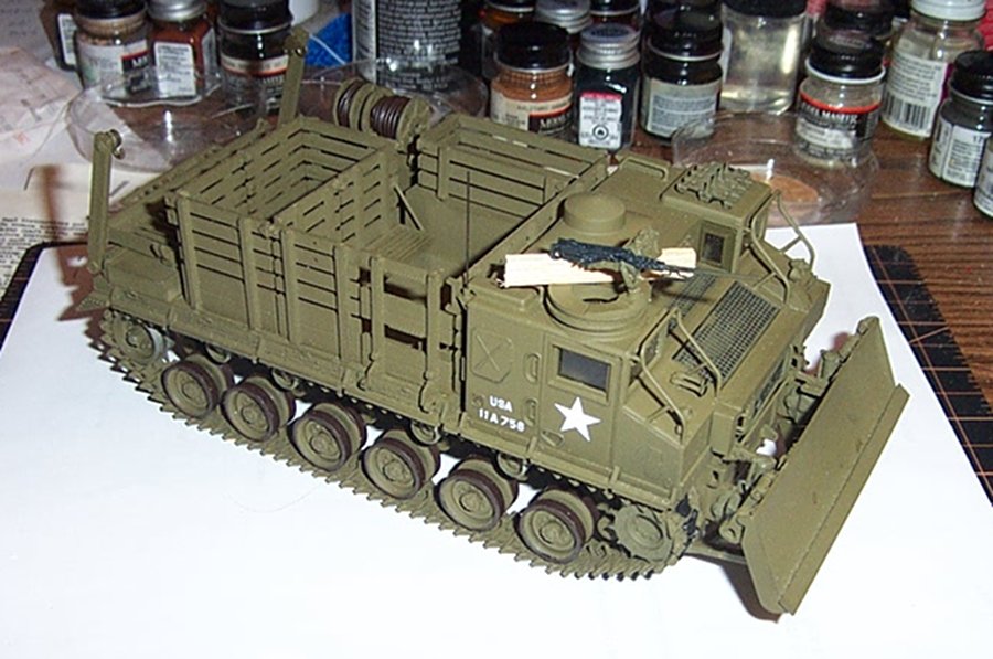
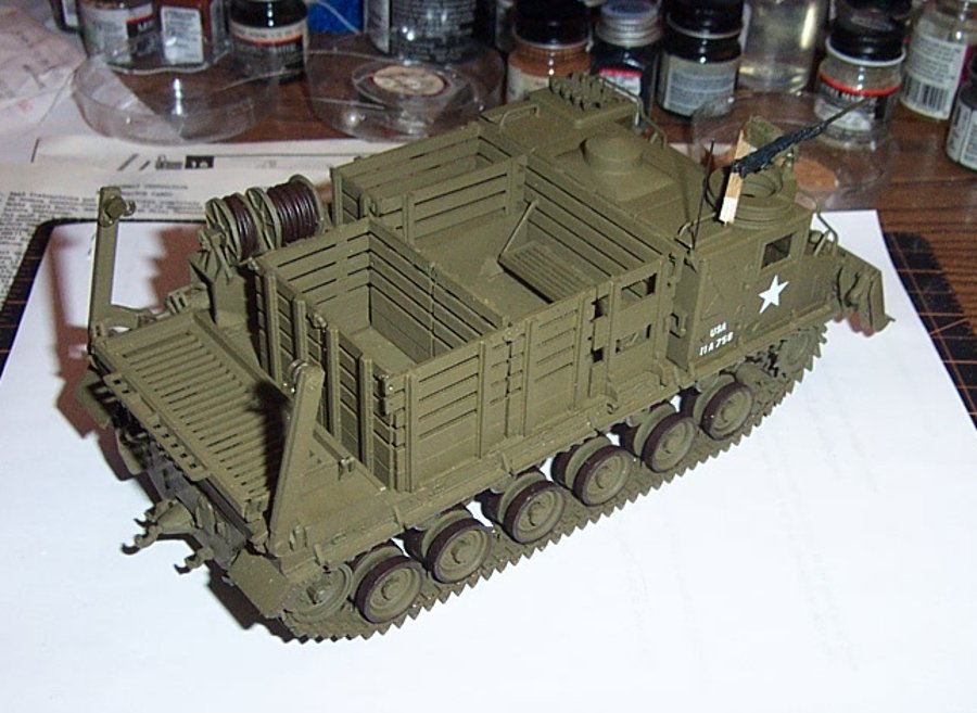
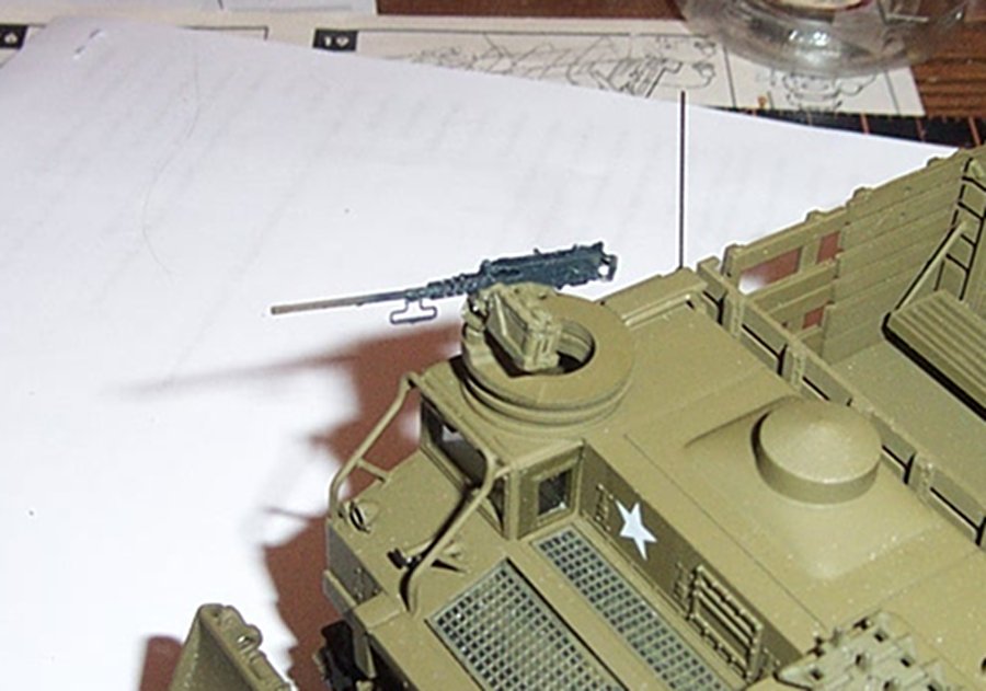
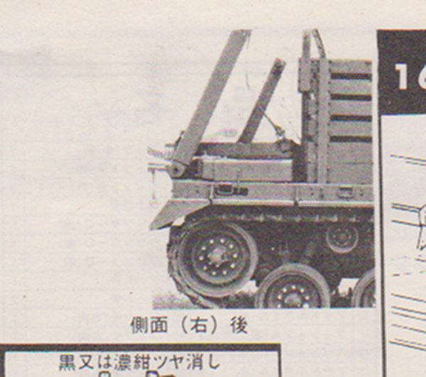
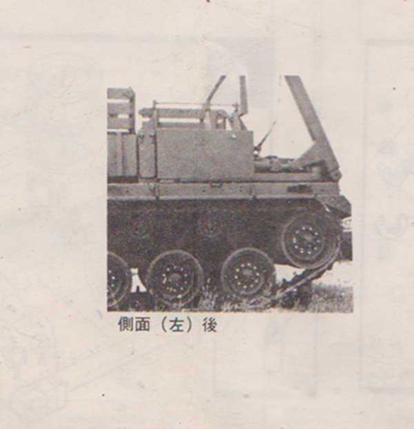
Finishing up the basic model kit...... Closeup..... Everything attached ready for details... Track details, and yes, I'm very pleased with AFV Club tracks, they do a lot for the look.... Left Front, almost finished, all that is left for the basic vehicle is to dress out the pallet/generator lift and the body bows. Right Front Close-up of the Asuka .50 cal. Said to be the best injection molded M2HB around, looks pretty good in my estimation. Right up there with the resin and PE kits. (better than most) This is set "B" which is vehicle mounted machine guns, they do have a set "A" which are tripod mounted infantry weapons. Comes with two guns in the package and covers mounted .50 cals covering WWII through Vietnam, kit # 35-L9, well worth it in my opinion.... (and I need to touch up the barrel) Right Rear, showing the 3 ton lift and pallet system. now the kit provides a length of thread to attach the four corners of the pallet to the lift's swivel hooks. Why go build a beautiful model and wreck it by tying knots with thread? Now in researching this I found that the previous build logs scattered around the internet show that the modelers decided that the best way to handle this was to substitute chain for the corner connections of the lift..... I have no doubt that at some point in time that chain was used in the field for this purpose but there are no photographic examples of this anywhere I could find.... (and no mention of it in the army tech manuals) Research shows that what was issued and used were cables, half inch thick, with ferruled loops on the ends and clevis's to attach them to the load.... Notice the lift at the rear? cables..... From the kit instructions.... Yep, cables and clevis's this is why the kit manufacturer gives you a length of thread... in the images you can make out the .5 inch, 1500lb test cable with ferruled loops on the ends and clevis's for connection to the pallet/generator. these are the only two pics of this I have and they come from the kits instructions. (which are obviously of a real vehicle) So how does one represent a 1/2" steel lift cable in 1/35th scale? I know WIRE! In my stash of hardware I happen to have some tiger tail jewelry wire... Measures about .015 in diameter (half inch in 1/35 is about .014) and it is also a twisted wire made of stainless, it sure fits the part... Next up, making the lift cables and testing their fit.....
- 70 replies
-
- 10
-
-
Thank you OC, I'm seriously enjoying the metal sided mud maker type of things also.......
-
Draggin up a chair.......
-
This was an original Nitto from the stash so it has the advantage of young molds. I don't know what the BlueTank re-issues are like but as far as detail and mold quality, this is right up there with Tamiya from 60 years ago... The quality is fantastic......