Egilman
-
Posts
4,385 -
Joined
-
Last visited
Content Type
Profiles
Forums
Gallery
Events
Everything posted by Egilman
-
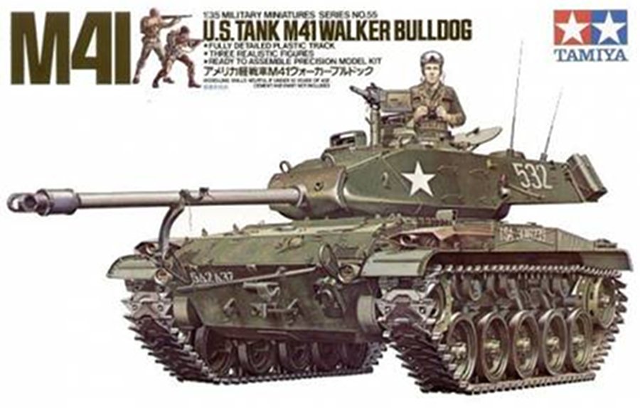
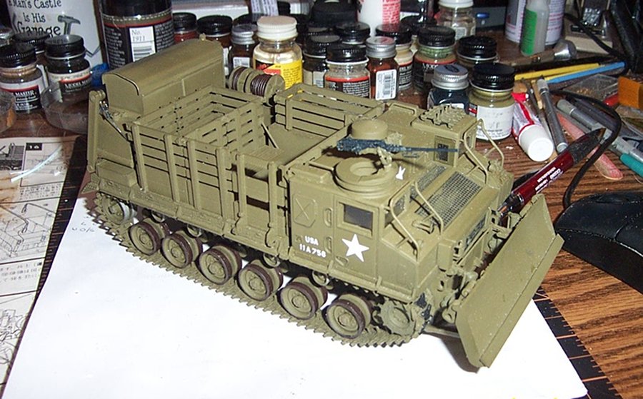
 You need two things the proper aftermarket tracks and the proper drive sprocket to fit the tracks.... Tracks; Two sets of AFV Club AF35046 T91E3 workable track, you need two sets as the kit tracks are for the Tamiya Walker bulldog which has only five road wheels and your M-8 HST has six. You will also need the Tamiya walker bulldog kit itself for the drive sprocket to fit the tracks..... Both vehicles used the same suspension/track components, it was designed that way.....
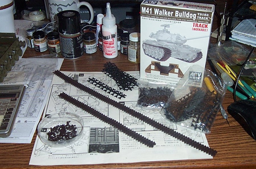
-
B-25J Mitchell by Tom E - Revell - 1:48 Scale - PLASTIC
Egilman replied to Tom E's topic in Non-ship/categorised builds
It's easy to paint the nose of the bomb one color it can be done in several ways, my trick is to dip the nose vertically in some thinned yellow paint. Once that is dry, dip it again in some Olive Drab paint thinned the same way, just not quite as far into the paint as you did the yellow.... Leaves a nice yellow ring, the only difficult part is making sure you have it vertical on each dip.... -
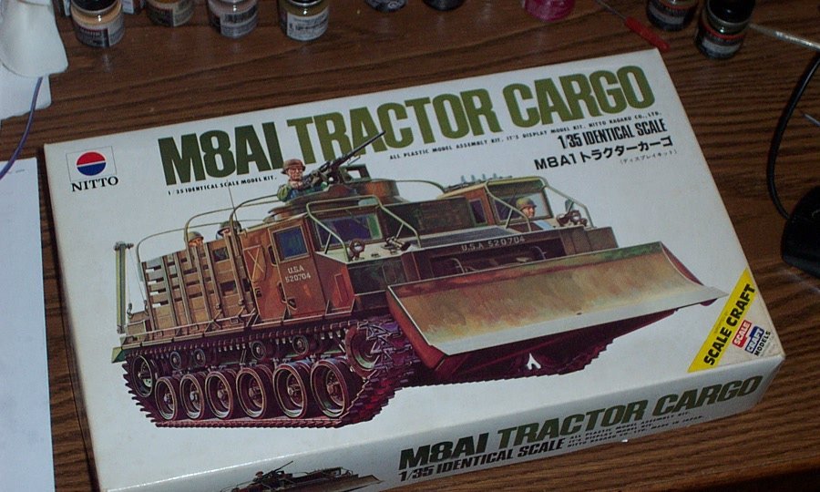
It's an original Nitto.... And yeah, those are the rubber band tracks that were used for the motorized version..... Aren't worth the powder to blow them to hell.... And thank you for the compliment.... I did a build log about her a while back before I discovered this fora.... I can tell you how to fix it....
-
I have absolutely no doubt that your shoulder was stiff the next day.... :-) Been there done that....
-
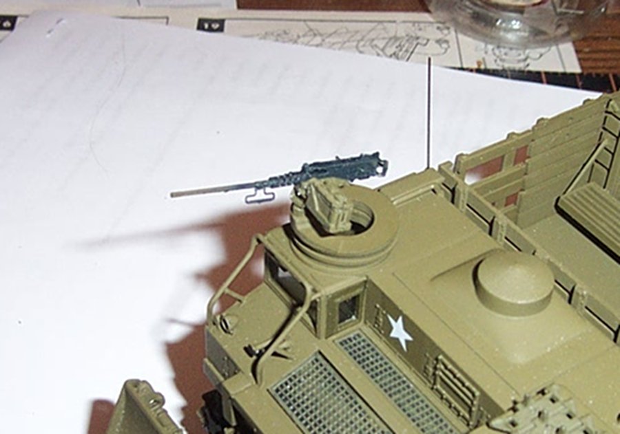
When Browning first designed the ma duce, (based upon the very successful M-1918 .30 cal) the army ordered it tested in continuous fire until destruction.... any one care to guess how many rounds went down range before it finally decided to quit firing? .......... 32,687 before the action finally broke...... (the barrel of course was destroyed long before the action quit) It is considered the most reliable gas operated heavy machine gun ever manufactured.....
-
Well I can show mine.... I still hadn't touched up the barrel in this photo.... Post Korean war vintage.... that's MM gunmetal with steel lowlights and MM rubber grips everything else (pedestal mount and cradle) is standard OD green.... (there no PE on that gun btw)
- 324 replies
-
- 10
-

-
Artistry in action.... It looks the part my friend, I cant wait to see it in it's house colors..... Beautiful detail work....
-
B-25J Mitchell by Tom E - Revell - 1:48 Scale - PLASTIC
Egilman replied to Tom E's topic in Non-ship/categorised builds
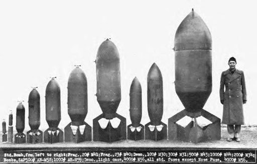
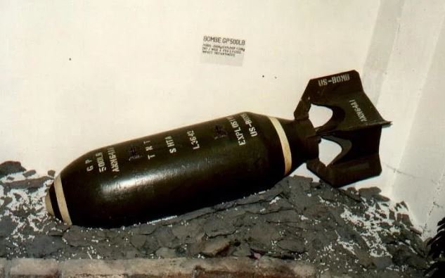
Those are mk 65 bombs..... originally designed in 1939 for the USAAF they were the general purpose design used throughout WWII and Korea, they were also used in Vietnam when the supply of Mk 80 bombs got low cause they were dropping them faster than they could make them..... It is an overall OD color with two yellow stripes fore and aft... fuses (there were three, nose contact, tail contact delay, and side radio altimeter) are colored steel or aluminium during WWII of painted green in Korea and Vietnam... the contact fuses were installed safed and had propellers that spun to activate them as they fell. they had two circular screw-in lugs on one side for hoisting and mounting into the bomb dispensers/racks They did come in various sizes and marks for different purposes, but the design was basically the same Mk 65 throughout WWII.... An example of a 500lb GP bomb from WWII... They still find several of these in Germany each year ranging from 250 lbs to 4000lbs.... unexploded.....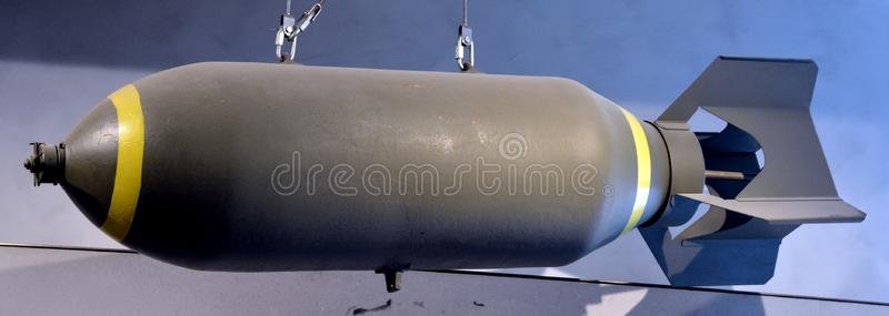
-
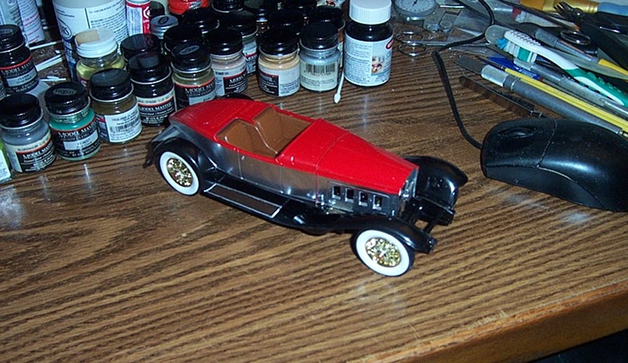
1931 Cadillac by CDW - FINISHED - JoHan - 1:25 Scale - PLASTIC
Egilman replied to CDW's topic in Non-ship/categorised builds
That green is going to sparkle under a high gloss finish.... I like it..... -
Good for you! The wife has been suffering from cabin fever the last few days but she is getting ready for some sun also..... (except the pollen is driving her nuts)
-
The Avia S-199's were actually built immediately postwar..... When Israel flew Nazi Planes Quote: 'The Avia S-99s & S-199's was constructed with parts and plans left over from Luftwaffe aircraft production that had taken place under the country’s German occupation of Czechoslovakia during the war." Were they made by the Nazi's? no, designed by a Nazi for the Nazi's yes.... Does a name change, change where they were created/originated from? or, what they were? Not in my opinion.... Not faulting the Israelis, they needed weapons and at that point in time the world was conspiring against them getting what they needed expecting the arabs to make short work of the jews... They couldn't get the proper engines for them because of the arms embargo so they obtained surplus Heinkel engines and props for them.... Made it a widow maker in service and quickly withdrawn when better aircraft became available...... they not only scored victories against Egyptian C-47's (modified into bombers) but over Syrian Spitfire's and Egyptian Mustangs...... Impressive if you ask me....
-
Would it surprise you to know that the fledgling Israeli Air Force flew modified Me-109's.......... in their early years......
-
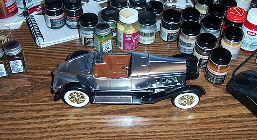
Thank you my friend.... I thought it was, as proposed, the chrome look was just too much.... so I figured to cut the metalized look by giving it layers that look normal to pull the eyes away from the rather drab look of all metal.... It's ok now, but wait til I get done with it..... My pleasure, and the paint I stripped was only on there for a day and a half, older paint might take a bit more time... But, it does work. And thank you for your comment..... Thank you all EG
-
I can hang with that, more artistry on display......
-
I don't know why they gave all the extras, probably for the people..... (Historical note: they should all be wearing the leather tanker helmet when in the tank, the reason is the steel pot was too large to wear while in the tank, it kept clunking into things. Eventually, most crews just ditched them)
-
Aston Martin DB5 by Fnick - FINISHED - Revell - 1:32
Egilman replied to fnick's topic in Non-ship/categorised builds
Wow the old Airfix by Craft Master kit.... VERY COOL! Is this the one with the operating parts? (like the ejection seat?) -
Not that bad for what your getting.... Rolife... (less on Evilbay) They have a whole selection, quite a few of them are very very nice....
-
Thanks Jack.... (as far as the seat positioning, I have been unable to find out a reason for it, design reasoning lost to history)
-
Honey, I shrunk the greenhouse...... {chuckle} Modeling is an infinite variety of worlds..... Very Very cool...... The best modeling is that which is done on request of a loved one.....
-
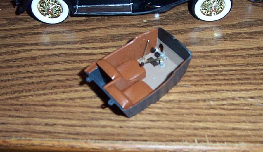
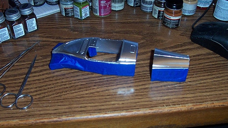
Now the cockpit is done as far as it can be at this point.... (still need the dash panel painted and detailed) Next comes the body, firewall and hood..... Now, with the body set on the chassis, it's beginning to show it's potential..... Masked up and ready for paint....... Onward.....
- 123 replies
-
- 16
-
-
Yep, that's why some of us call it a journey......
-
The LCT was specifically designed for the Sherman Tank.... If they had issued Pershing's when they first had them, they would have been designed to handle those instead.....
-
Bell UH-1H Huey By lmagna - Dragon - 1/35 - PLASTIC
Egilman replied to lmagna's topic in Non-ship/categorised builds
Just a note, from the factory, (Bell Helicopter) the dash panels were grey, same grey as the rest of the interior..... They were painted black by the receiving station/unit on the order of the commanding general that felt they would be better black..... (less glare or some such opinion) And there are lots of examples that not all of them got painted... Looks spot on to me....... -
That is the thing about what are now called the Pocher Classic 1/8th scale kits, when done with patience and skill, they become "Honey, I shrunk the car" representations..... Nothing tops them in the details.....