HOLIDAY DONATION DRIVE - SUPPORT MSW - DO YOUR PART TO KEEP THIS GREAT FORUM GOING! (78 donations so far out of 49,000 members - C'mon guys!)
×
Model Mariner
-
Posts
95 -
Joined
-
Last visited
Content Type
Profiles
Forums
Gallery
Events
Everything posted by Model Mariner
-
 I guess it would be a good idea if Seawatch books would have a European publishing company to print and distribute their books in Europe. Shipping their books to the EU (plus customs duty) makes the books extremely expensive. I suppose there are a lot of Europeans who would appreciate this Klaus
 -
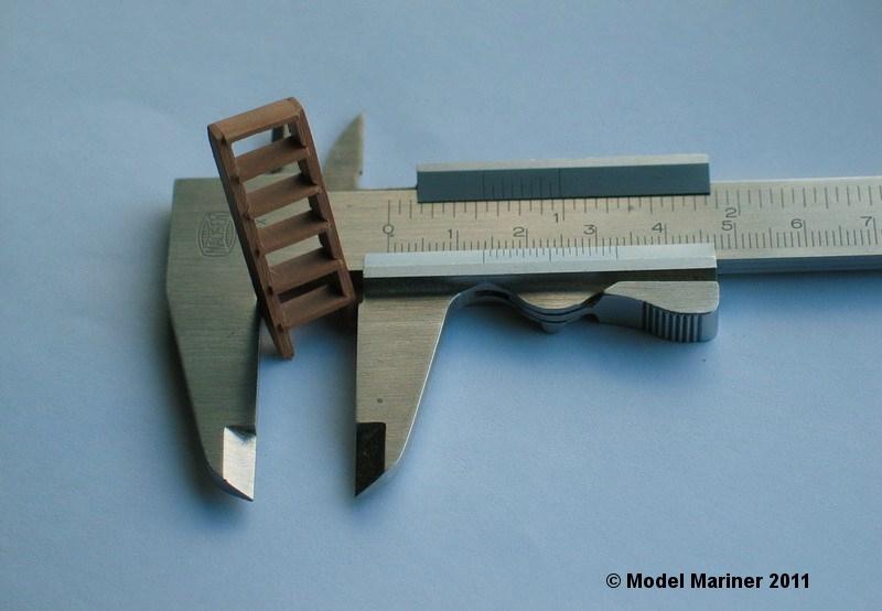
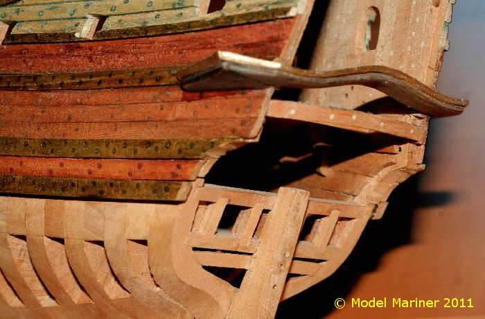
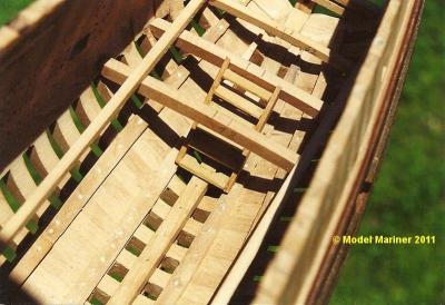
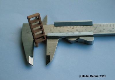
The first deckbeams as well as the ladder down to the hold are built in: the longitudinal square batten is not part of the model and serves only to align the deck beams close up of the ladder: The wales and a several strakes of outer planking are fitted: the plankes are treenailedtwice at every second futtock respectively toptimber, the wales are treenailed twice at each first and second futtock. a few more strakes and the klinker planking at the poop are added: the outer planking is nearly finished: Klaus


-
Very nice model Ilhan Klaus
-
Hi Alex This is one of my favorites here - I always admire the precision of your work Klaus
-
Good to see this log back Klaus
-
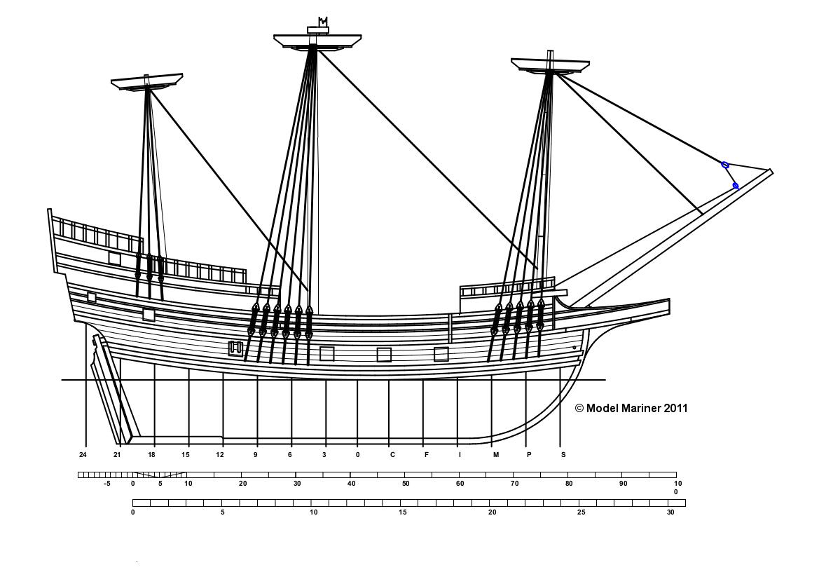
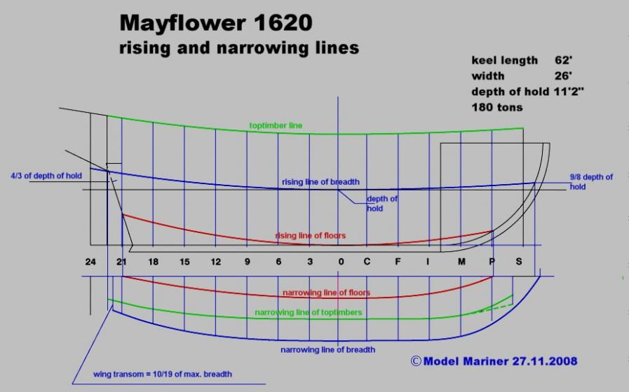
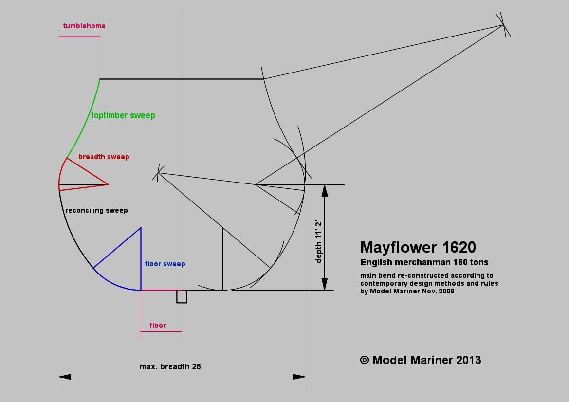
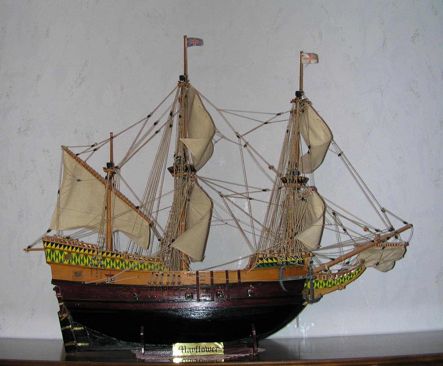
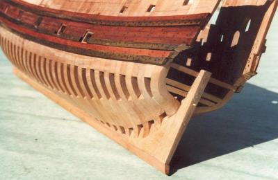
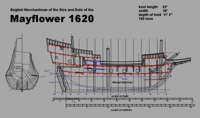
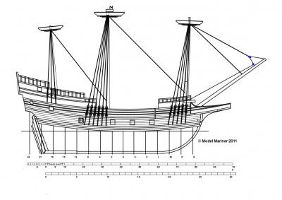
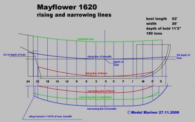
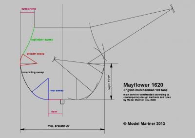
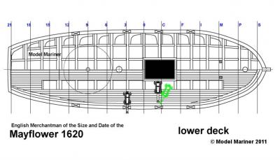
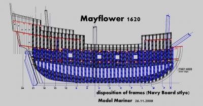
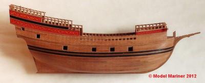
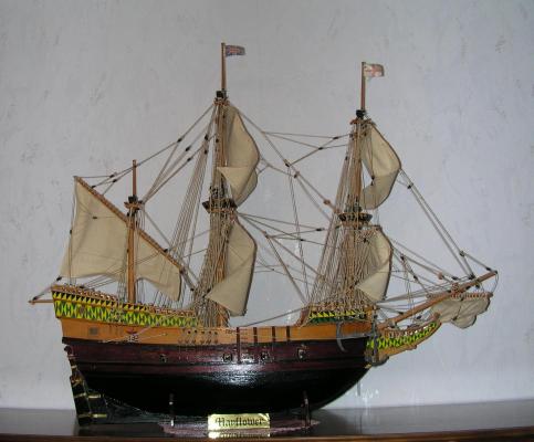
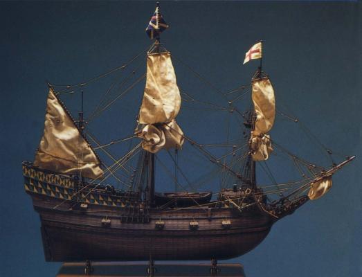
Since I am interested not only in modeling but also very much in reconstruction of ships of the 17th and 18th century I have started this project (several years ago). As a boy I have built a model of the Mayflower from a German kit (Graupner Modelllbau). The plans for this model were well drawn but historically certainly not correct. The model was obviously designed to resemble closely the Mayflower model designed and built by R C Anderson for the Pilgrim Society Plymouth, Mass. In the 1920s but the lines of the hull were certainly far away from authentic. The following 2 pictures show a model from a Graupner kit (although not mine) in comparison to a model built from R C Anderson's plans It has been on my mind for many years to try my own reconstruction of the Mayflower based on whatever reliable information could be found and when I found Chuck’s build log of his Mayflower model on MSW this idea came back. Regarding reliable information for a Mayflower re-construction one has to say that there are only two hard facts about the Mayflower: 1. nobody knows really what she has looked like, there are no plans, no pictures or paintings and no description of her available she had a burden of approx. 180 tons With the Mayflower we have the same situation as with other historic ships like the Santa Maria, Golden Hind and several others: we can reconstruct the ship only so far that we can say “she might have looked like this” using general information about ships of the period or documented dimensions of ships of similar size. Fortunately there are several contemporary documents available which enable us to determine the dimensions and the shape of a hull of known tonnage within certain limits. Apart from the so-called Fragments of Early English Shipwrigthy (Matthew Baker) the most important is a Treatise on Shipbuilding by an anonymous author believed to have been written about 1620 and on this my reconstruction attempt is mainly based. Furthermore I have used some other contemporary data and design rules mentioned in Brian Lavery’s „The Colonial Merchantman Susan Constant 1605”. Before starting the actual build log I’d like to present some parts of my plans (still far away from being completed): The next picture is a frame disposition in the style of the Navy Board models: and the last picture for today shows the current status of my model: Klaus
-
Thanks Brian you are building a POF model of Fubbs? I hope we can see a build log soon! Klaus
-
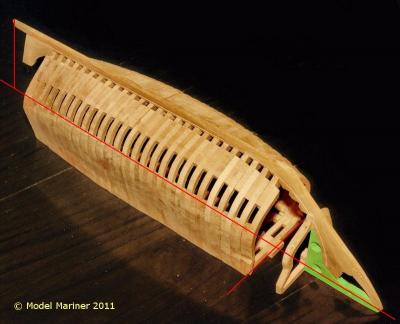
Thanks Mark When making and assembling the stem, keel and apron I left some additional material (shaded green in the following picture) at the inner side of the apron, the upper edge of which again corresponded to my reference height. This assembly was then fixed with the help of a wooden jig at a flat surface on to which the centerline as well as some square auxiliary lines were drawn. The keel was then aligned horizontally and exactly vertically over the centerline. The centerline and the square auxiliary lines together with the keel served as a guide to align the frames properly. A view to the finished framing from below: Klaus
-
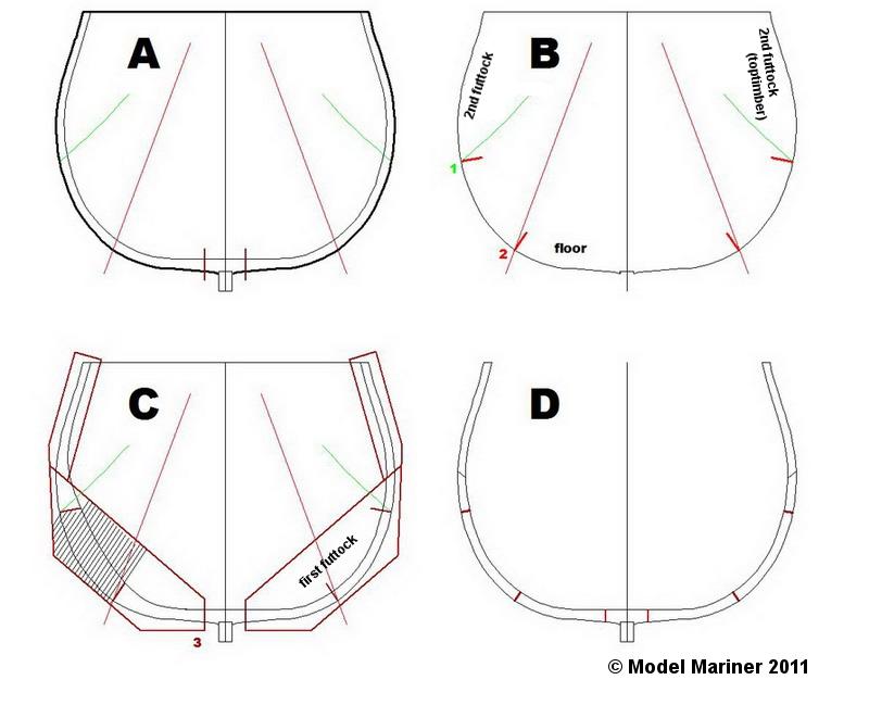
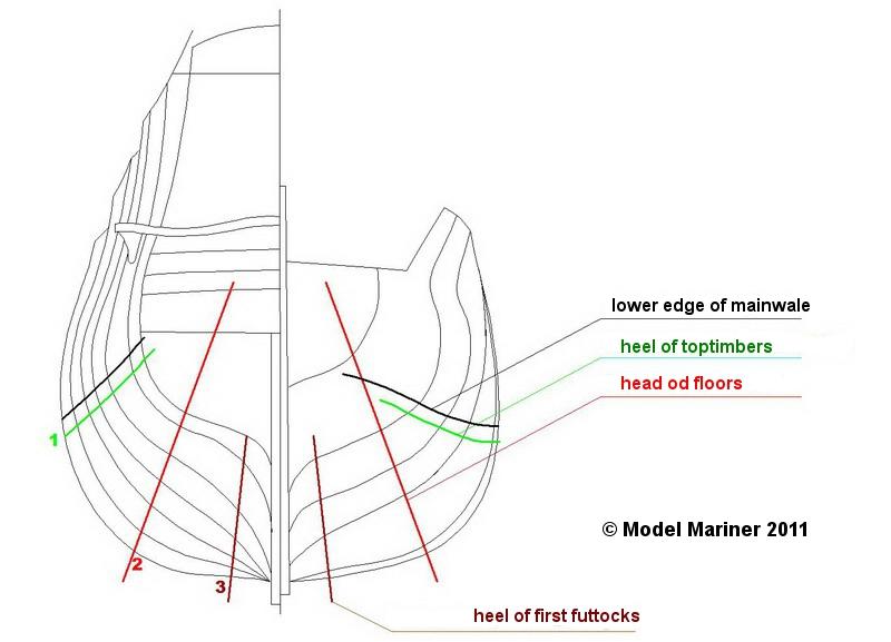
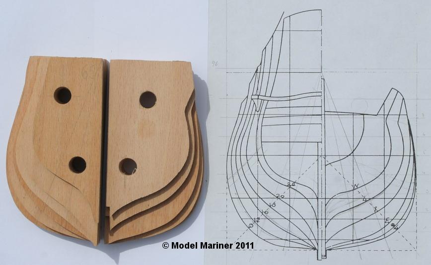
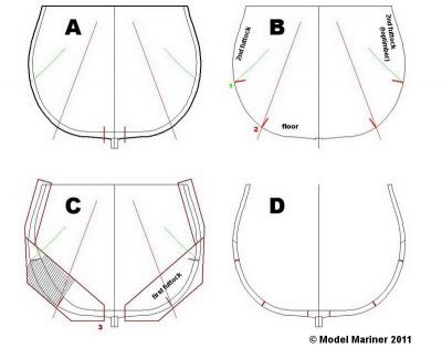
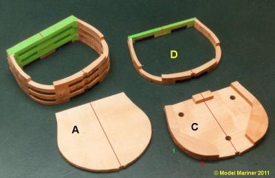
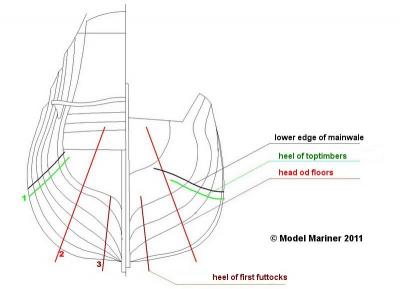
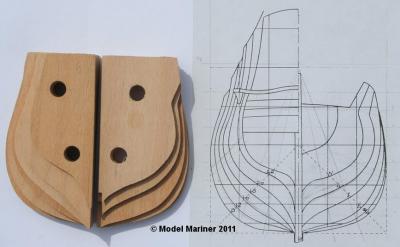
Making the frames: Since my model is rather small I choose a method of frame making which produces quite an amount of waste wood but safes a lot of work. At each double frame the floors and second futtocks are in the same plane and are overlapped by the first futtock and toptimber in a second plane. I have sawn out each first plane as a whole unit (A in the pictures) and made then a short cut vertical to the outer surface at points 1 and 2 (red lines in B). Then I glued parts as shown in C as a second layer onto the first one, these parts will later become the first futtocks and toptimbers. When glueing the parts together care was taken not to get glue onto the hatched area (shown only at the left hand side). After cutting out the outer contour of the first futtocks and toptimbers and the inner contour of both layers the part between the cuts 1 and 2 falls out and the result we have the double frame D. All toptimbers were prolonged to a reference height. When cutting out the inner part I did not cut away the uppermost part (marked green in the following photograph), this serves as a temporary stiffener, the upper edge of these cross pieces is at the level of my reference height. On these cross pieces the centerline was marked in pencil (marked red in the following picture). The heads and feet of the various frame components are located along the colored lines indicated in the body plan in the next picture. It seems that for Navy Board models these lines were made just arbitrary so that the ends oft the frame components followed fair curves, maybe they were also made with the help of flexible batons. These lines did not necessarily correspond to the actual position of the timber ends of the full sized ship. Klaus
-
This is good news. In fact I intended to copy the essentials of your log with all pictures but had not yet the time to do it and then it was suddently too late. Lookin gforward to getting this chance again. Klaus
-
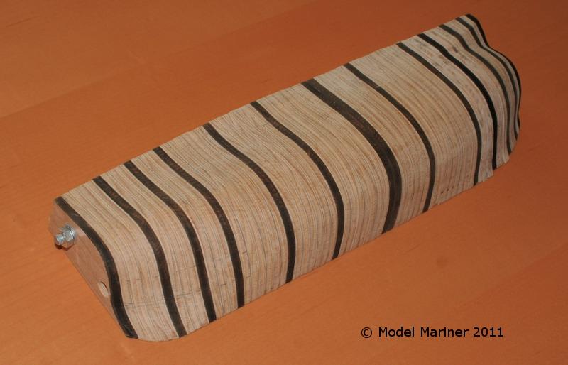
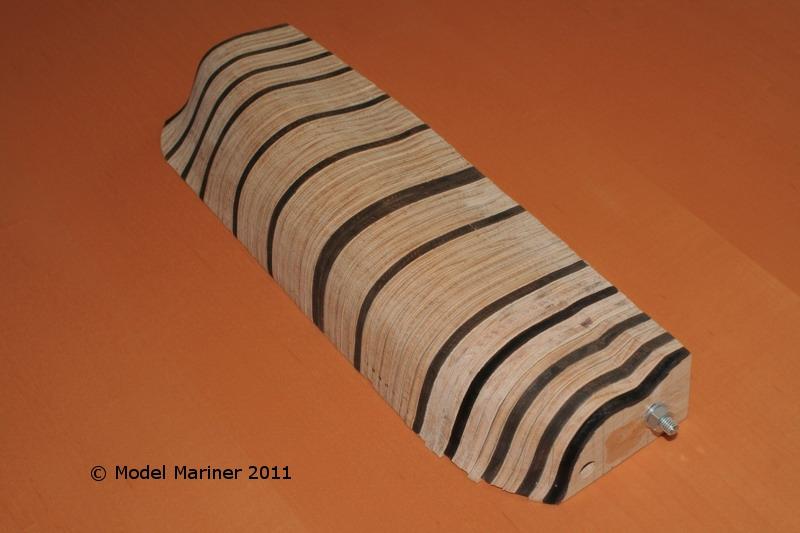
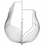
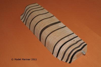
Making frame templates: The line drawings show only 13 stations, for this reason I had at first to work out the shape oft the stations in between. This could of course have been done by means of drawings but I considered this to be too much work so, I choose another approach. I have built at first a half model consisting of half frames (or rather bulkheads) made of plywood in the same thickness as the envisaged final pear wood frames. After sawing out the 13 half frames according to the line drawing I made several others of the same size to fill the empty space in between these 13 ones. After numbering all these half frames from stern to bow I have drilled 2 holes into each one, cemented them together with rubber cement and bolted them togheter by means of two threaded rods. So I got a solid stepped half hull which I sanded then into the required shape using the first 13 half frames as a guide. After taking out the threaded rods I could break the hull easily apart and had as result templates for all frames (for this reason the frames were all numbered. Unfortunately I did not take a picture oft he stepped hull (whe I made this I did not have a build log in mind) but I have assembled the frame templates once more for the following photographs later on, some of the frames were stained dark brown for sake of clarity. Klaus

-
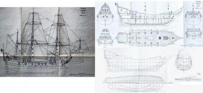
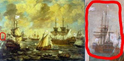
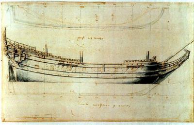
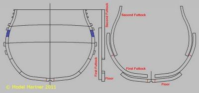
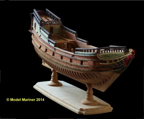
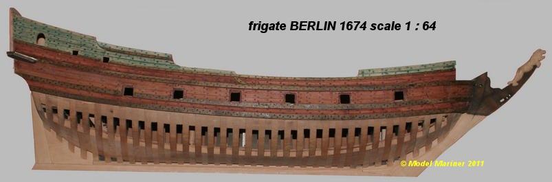
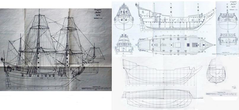
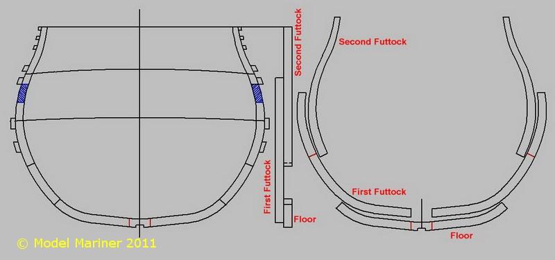
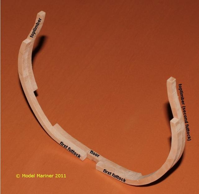
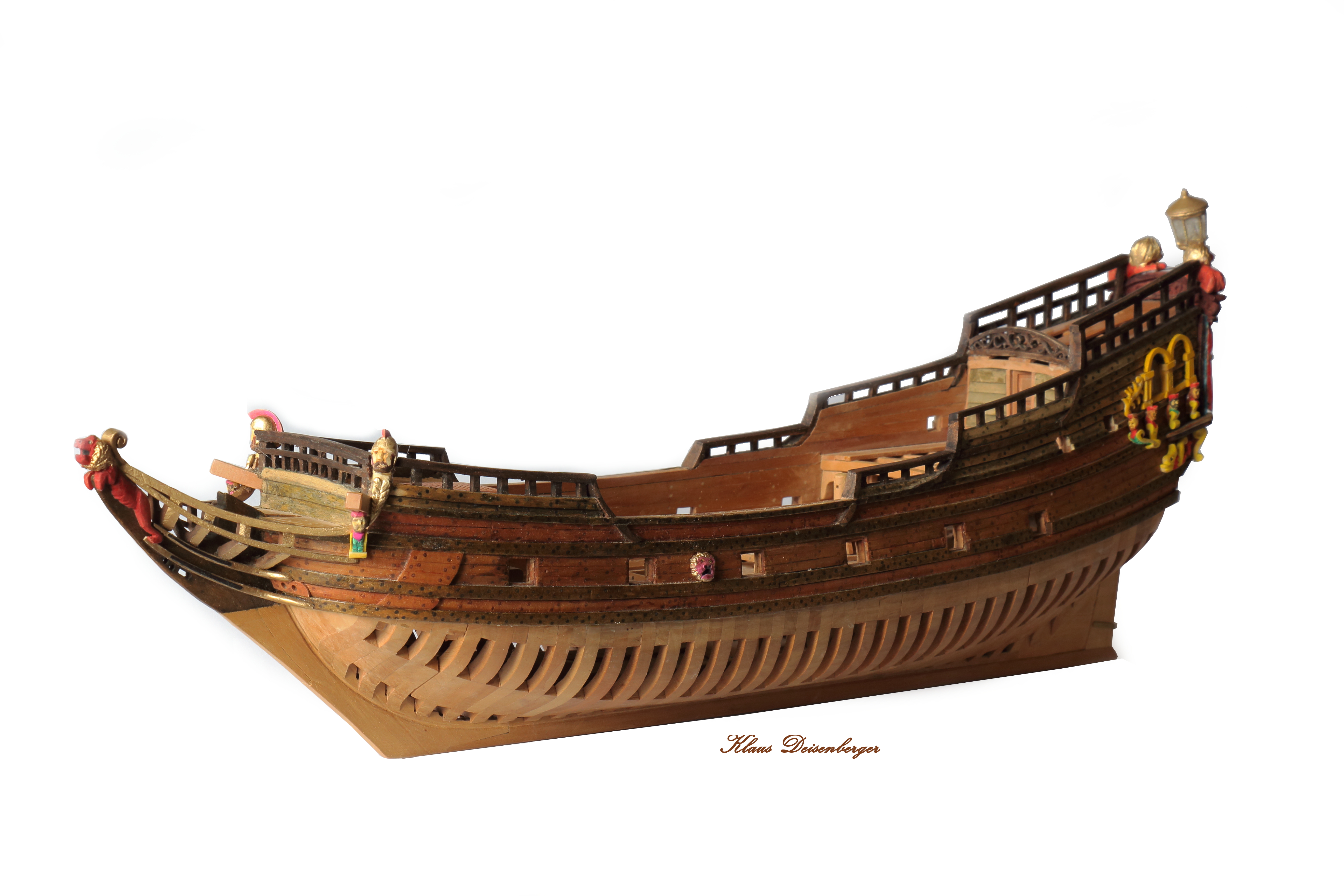
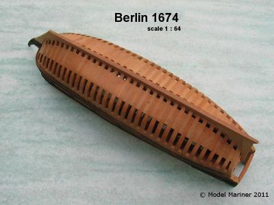
Hi all! Like most members I don't have a backup of my (lost) logs but since I have a log in a German forum in parallel as well I can re-create it nearly as it was (without the replies from other members of course) by translating the German version, but this will take some time. But to begin with here is a picture of my model as it looks now: Introduction: Data and sources of the model and the ship: All (or better the little) I know about the frigate Berlin goes back to the appropriate chapter (by Hans Szymanski) in the book Buch „Risse von Schiffen des 16. und 17. Jahrhunderts“, Verlag Delius Klasing (now out of print) and the plans attached the book. These plans are a re-construction done by Horst Hoeckel in the 1930s . Dimensions: Length: 80 ft – 22,65 m Breadth: 22 ft – 6,23 m Armament: 10 four-pounders, 2 three-pounders and 3 two-pounders Horst Szymanski mentions in the book that Hoeckel came to slightly different dimensions when making his re-construction. Unfortunately no sources are mentioned in the book. There is a contemporary painting (1684) by the Dutch artist Lieve Pietersz Verschuir showing the fleet oft he elector of Brandenburg on which also the Berlin is shown (relatively small in the background – marked in red) I don’t know if the original painting is large enough to show sufficient details as basis for a reliable re-construction. I could not find any other sources or information for the original ship. All kits or plans of Berlin which I have seen seem to go back to Hoeckel’s re-construction. This again obviously is based on a contemporary plan of a Dutch pinnace in the Scheepvaartmuseum (maritime museum) in Amsterdam. There are no original plans of Berlin and no other contemporary painting of her exists and I believe that from the painting shown above it is even not clear if Berlin was really a single decked pinnace or a small twodecker (as other Brandenburgish frigates were). So maybe Hoeckel was right in assuming that Berlin looked similar to this Pinnace, maybe not. I believe however that a full size replica built according to Hoeckel‘s plan would not have looked odd in a Dutch harbour in the second half of the 17th century. Short history oft he ship: The ship is a pinnace and was built 1674 in the Dutch province Zeeland on account of Benjamin Raule, the organizer of the navy of the elector Friedrich Wilhelm of Brandenburg, who has then chartered the ship from Raule. From 1676 to 1678 the ship operated in the Baltic Sea against Sweden. In 1679 six Brandenburg warships - one of them the Berlin - seized several merchant vessels of Hamburg, 1680 Berlin together with four other frigates captured the Spanish 50 gun ship „Carolus Secundus“, afterwards until 1681 the Berlin together with some other ships operated in the West Indies, were three Spanish ships were taken. In 1687 Berlin sailed as ship of the „Brandenburgish Africa Company“ to West Africa and was confiscated by the „Dutch Westindia Company“ in 1688 and this was the end of Berlin’s career as a Brandenburgish warship. The model: I have built the model in the particular style oft he English Navy Board models. I am aware that it is to some extent a contradiction to build a model of a Dutch ship in the way English Navy board models were built in the 17th century) but this model is a way for me to study this building method and to learn about the difficulties connected with it by building a small model (without doing a lot of research) before turning over to something bigger (what I have in mind is building a Navy board model of HMS Resolution 1667 based on my own re-construction) length oft he model: approx. 450 mm (17 ¾“) from figurehead to taffrail scale: 1: 64 resp. 3/16 inch per foot material: pear maple fort he green stained klinker planking and the blue stained planking of the stern and some carvings Framing of a Navy Board model: Before I begin the actual build log I‘d like to explain shortly the particular style of framing of English Navy Board models: The frames consist of floor, first and second futtocks (toptimbers), the hull is not planked below the main wales. The decks consist of deck beams, carlings and ledges and are only partially planked to allow a view to the interior. Some experts believe this method of framing is just stylized, others believe that English ships were really built like this in the early 17th century. This particular style of framing has however been retained (with some small alterations) for Navy board models until about the mid 18th century. The following picture shows the typical arrangement of a frame of a Navy board model consising of floor, first futtock and second futtock. On the left hand side the midship frame (in this case my own re-construction of HMS Resolution), in the center the side view and on the right hand side the individual parts, the red marks show the position of the feet of the first and second futtocks And this shows the same in wood: There were different variaties of Navy board framing but it is not the object of this log to describe them all. For all interested in this subject I recommend the book Navy Board Ship Models 1650 – 1750 by John Franklin. Navy board models were not planked below the main wale. The decks were built accurately from all required parts i. e. deckbeams, carlings, ledges, knees etc. but the planking was carried out only partially. The next part will deal with the building of the framing of the model cheers Klaus