HOLIDAY DONATION DRIVE - SUPPORT MSW - DO YOUR PART TO KEEP THIS GREAT FORUM GOING! (Only 13 donations so far - C'mon guys!)
×


HakeZou
-
Posts
325 -
Joined
-
Last visited
Content Type
Profiles
Forums
Gallery
Events
Everything posted by HakeZou
-
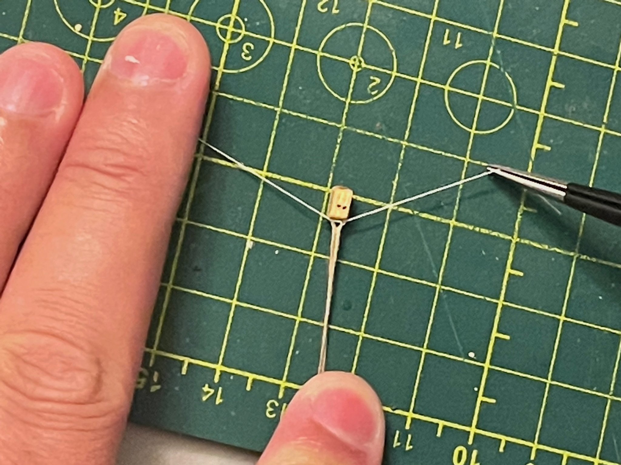
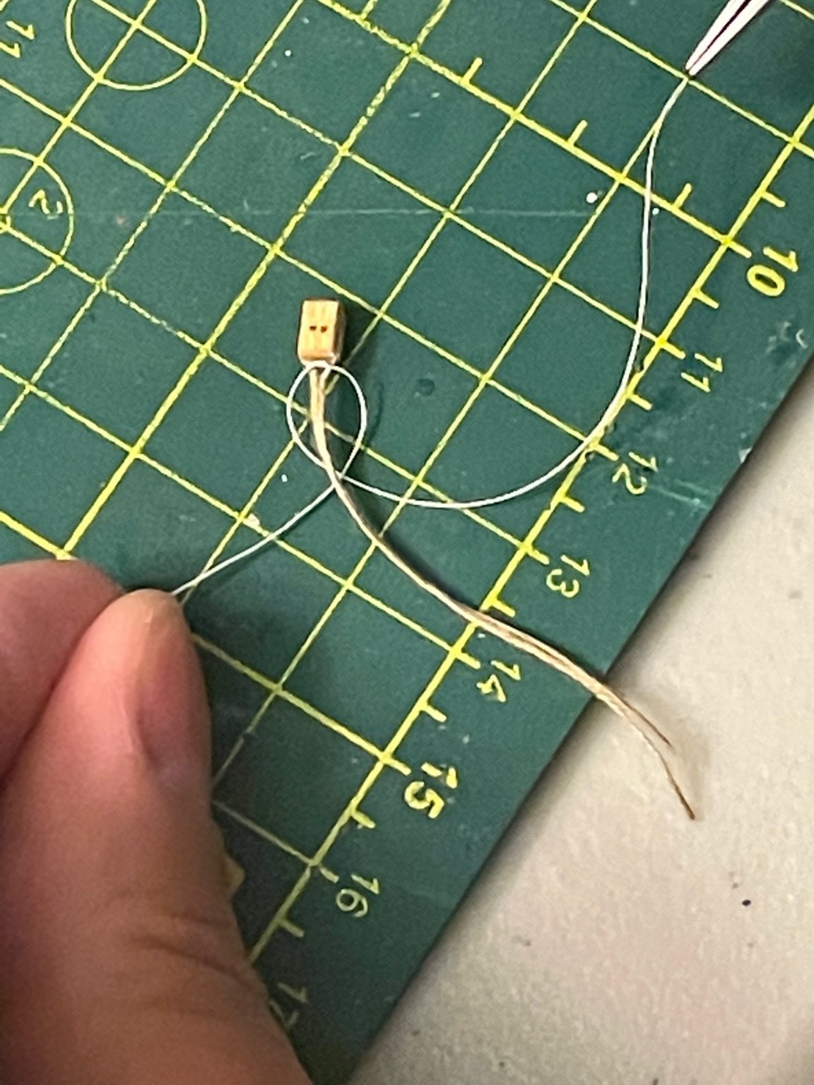
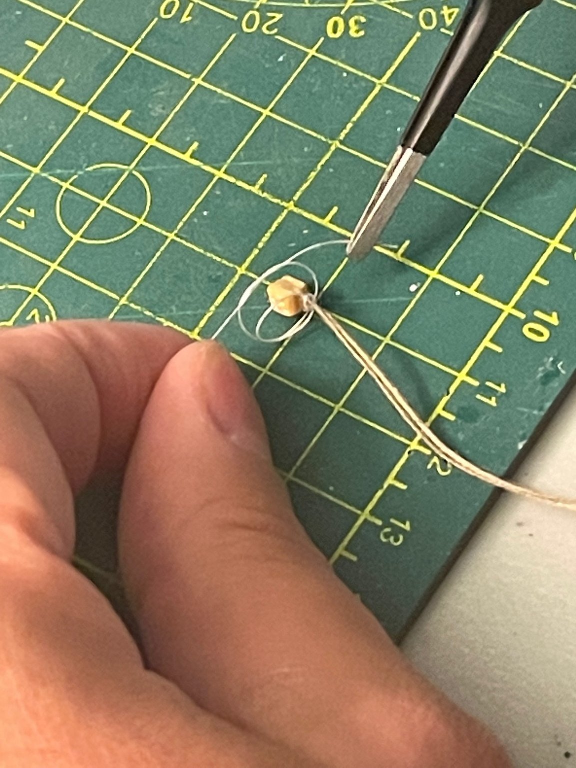
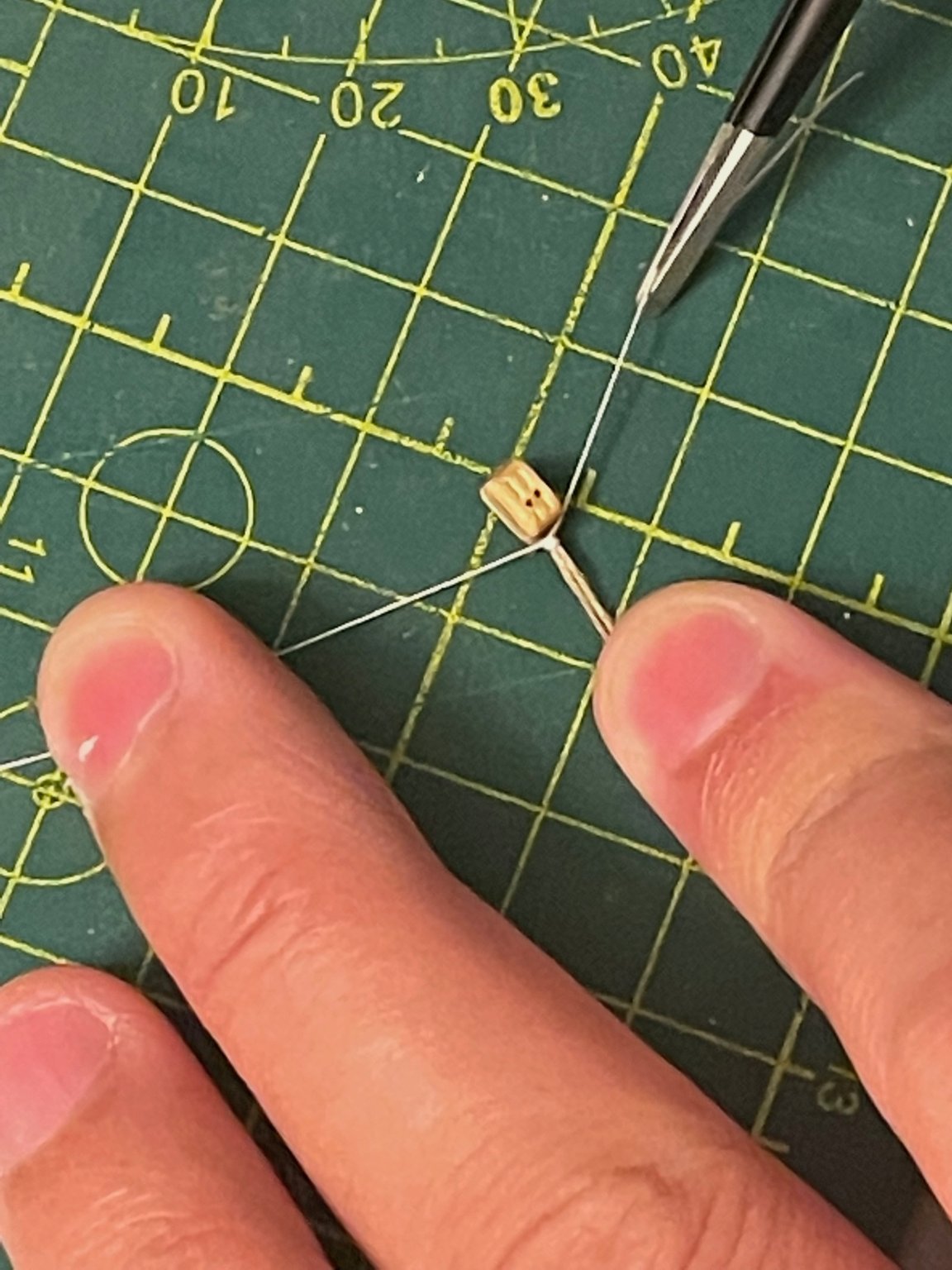
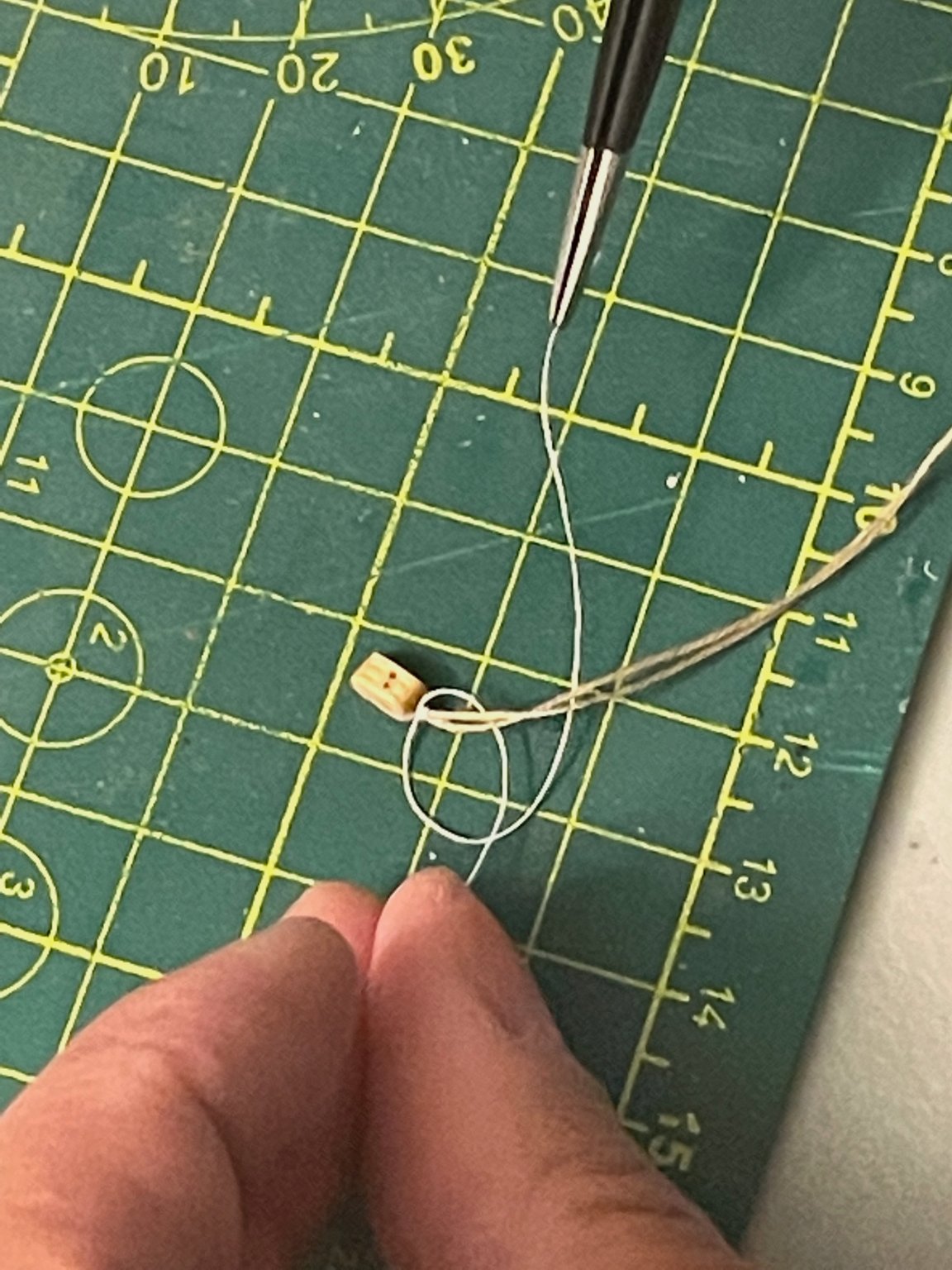
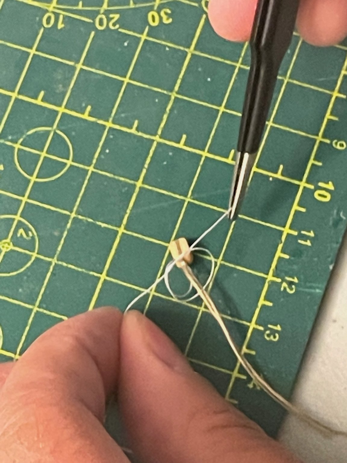
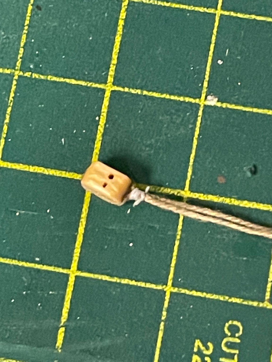
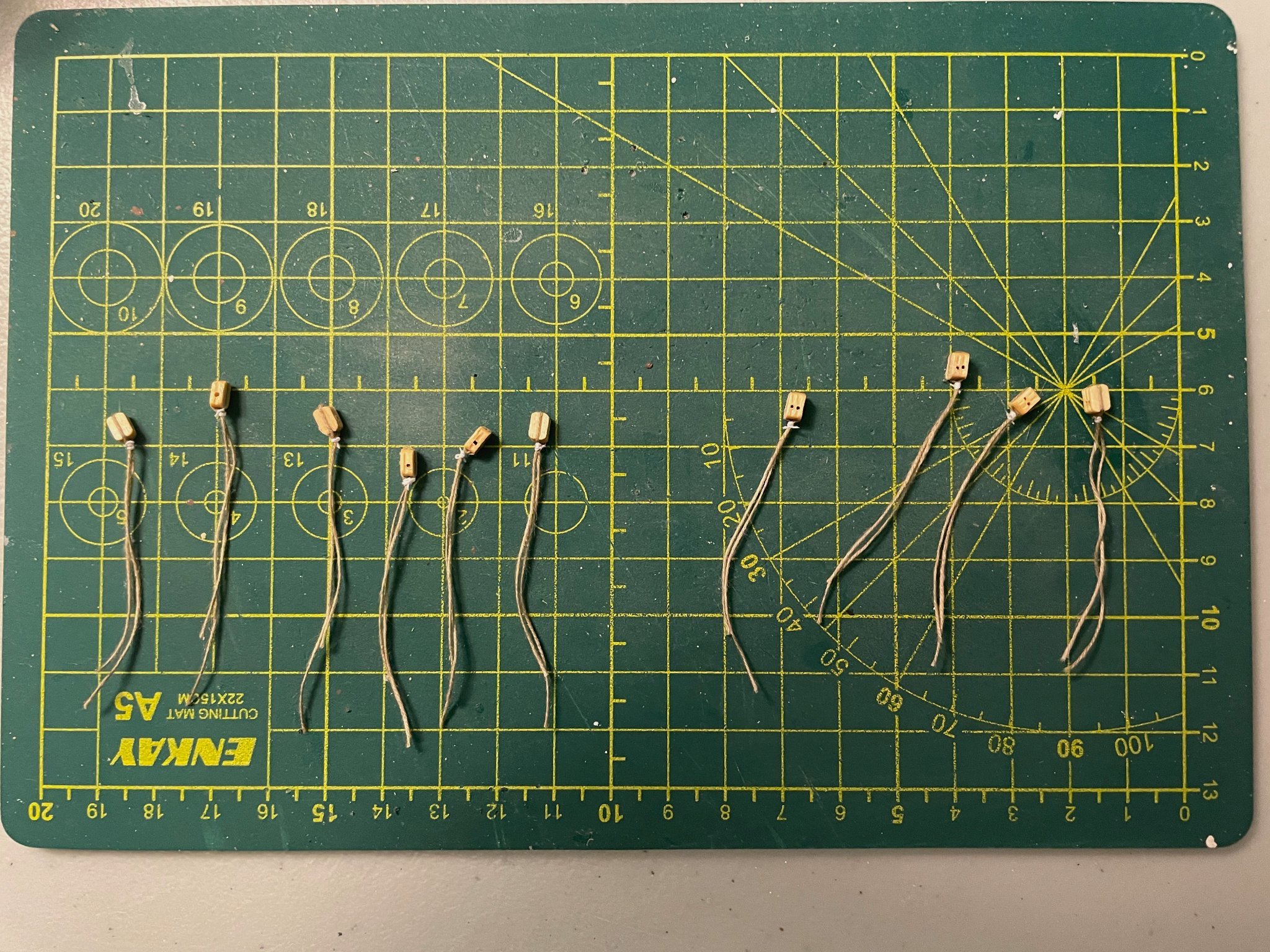
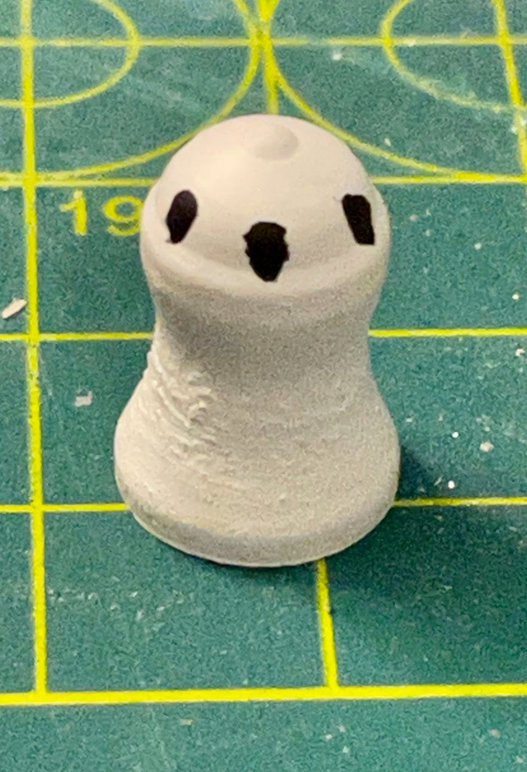
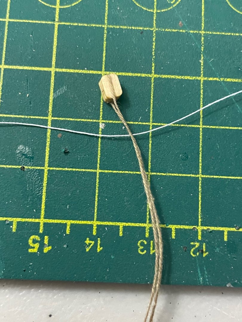
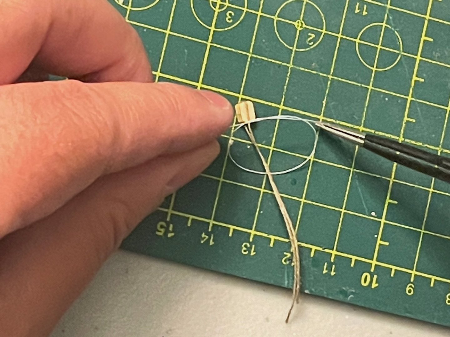
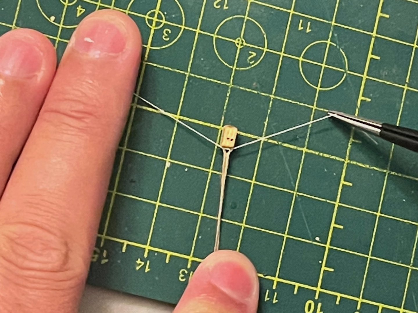
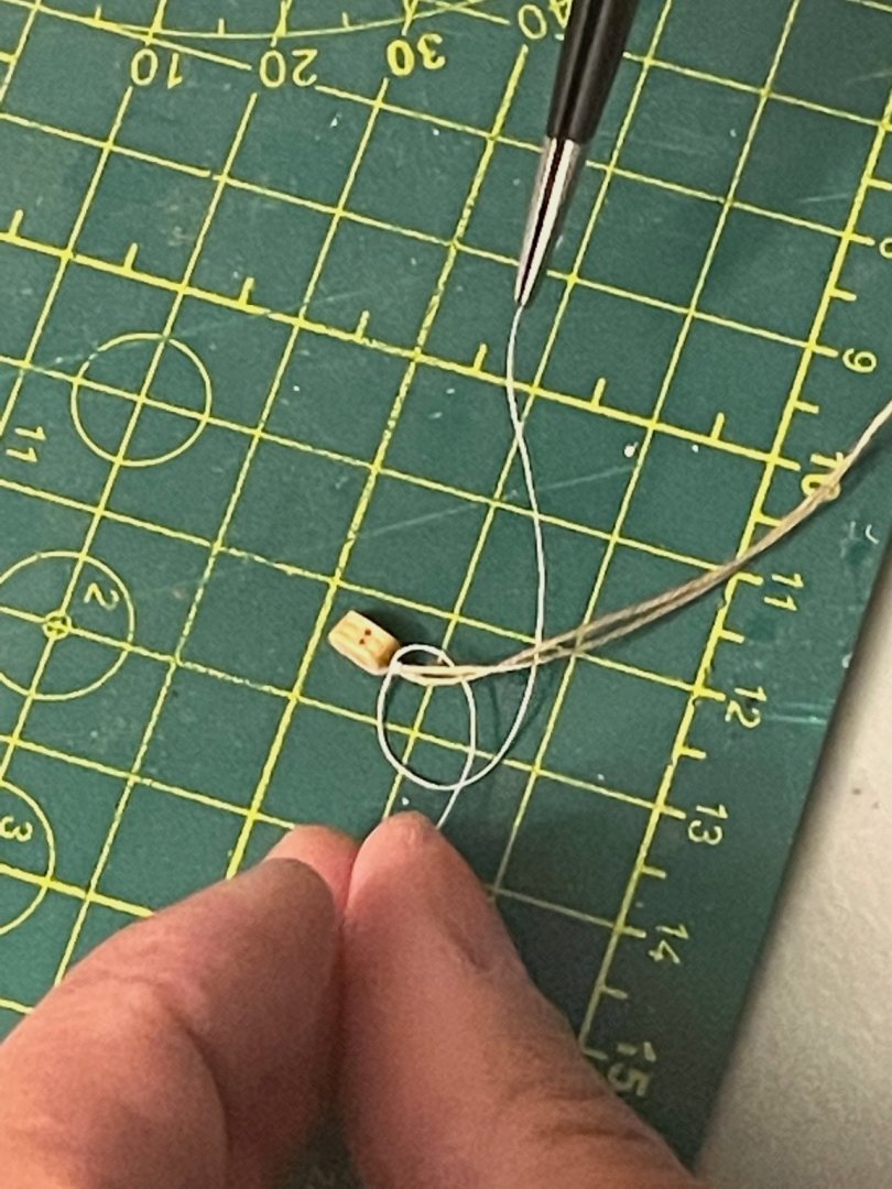
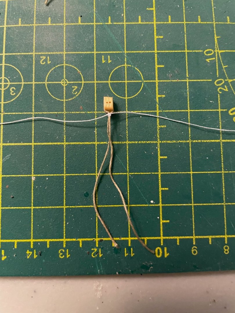
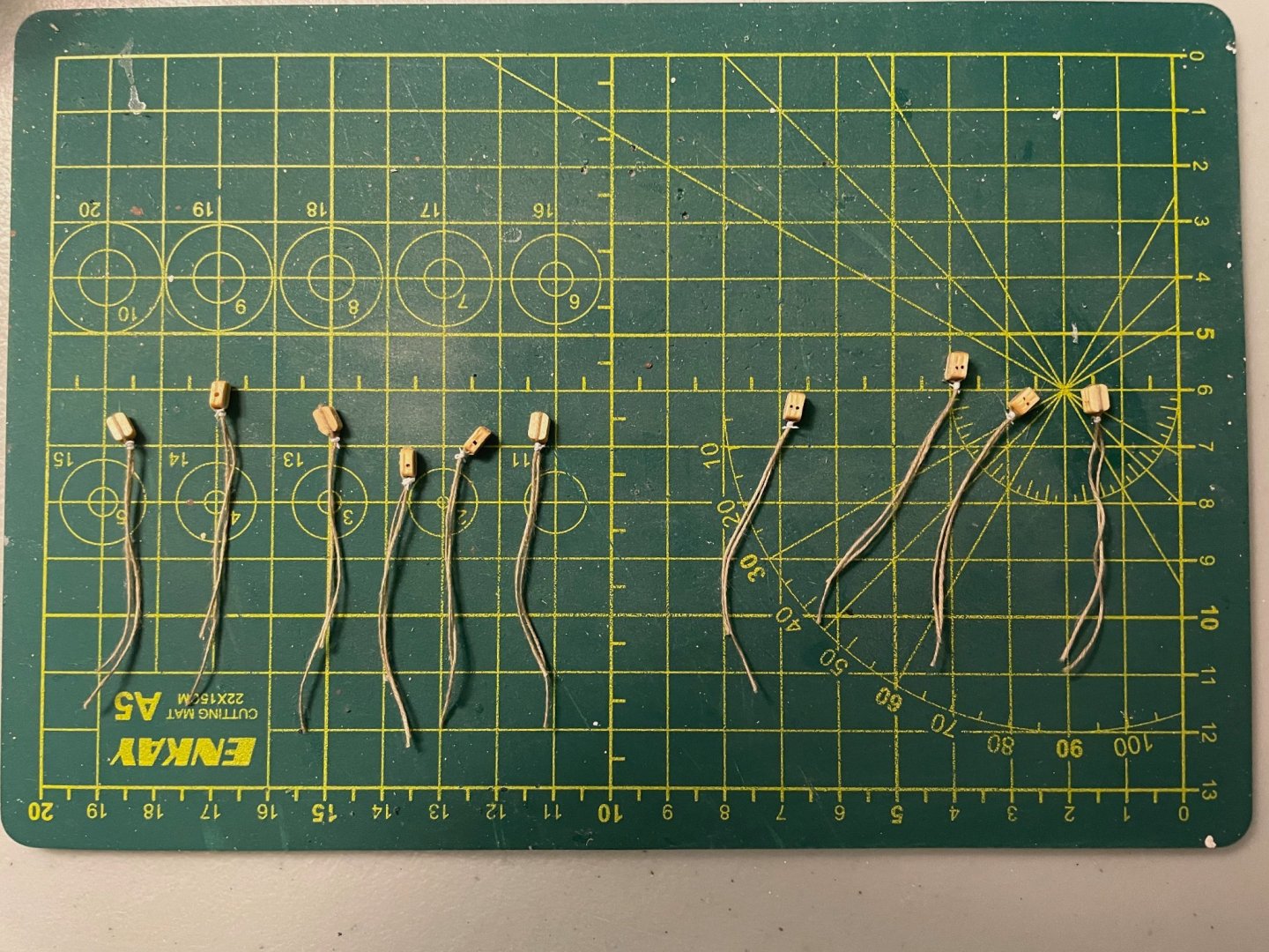
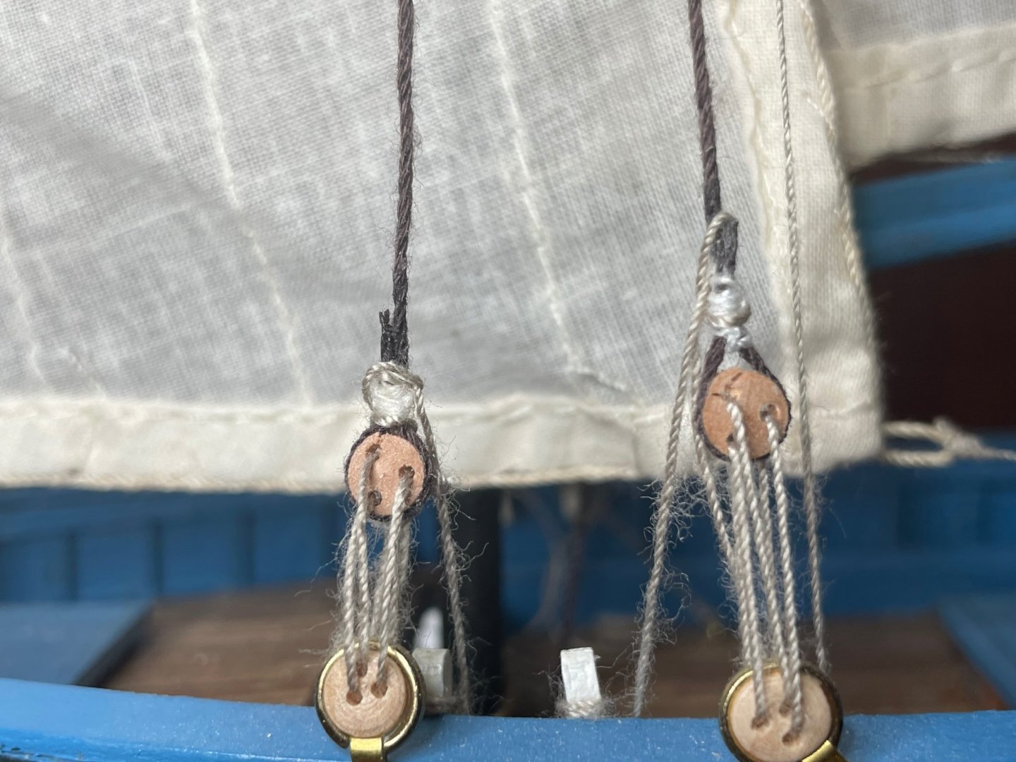
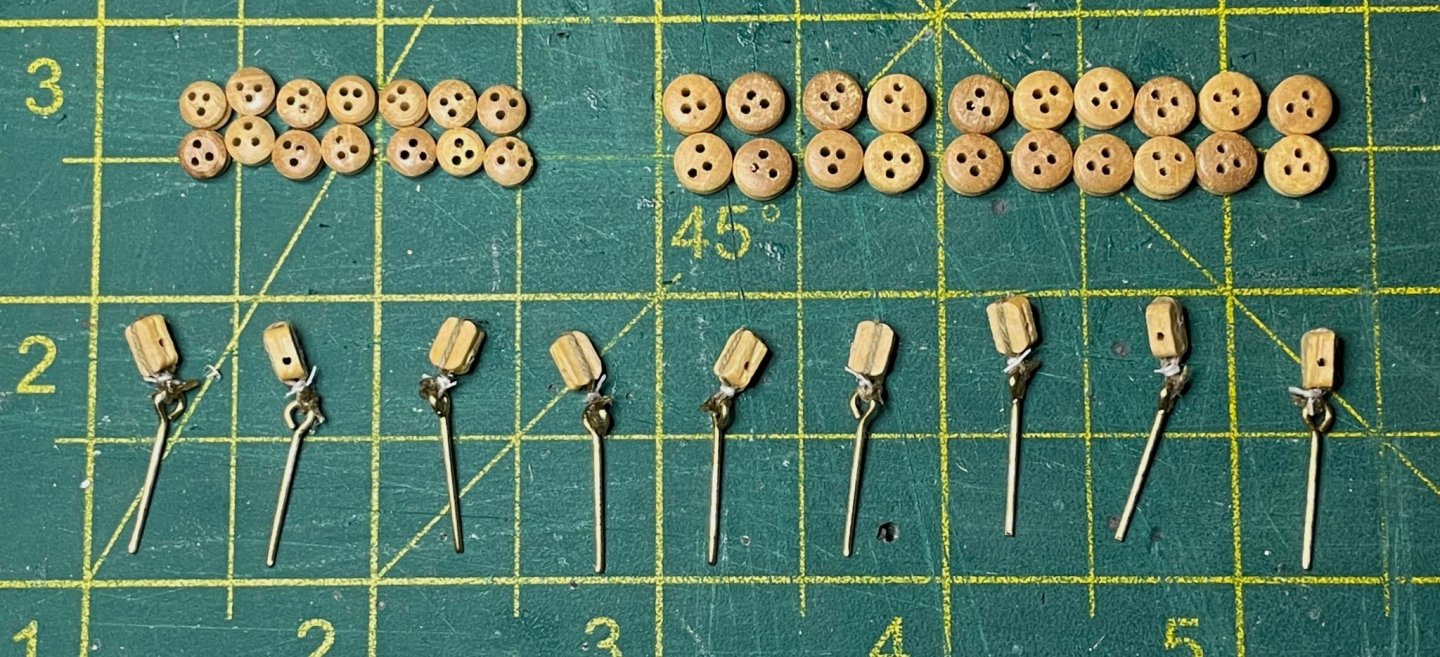
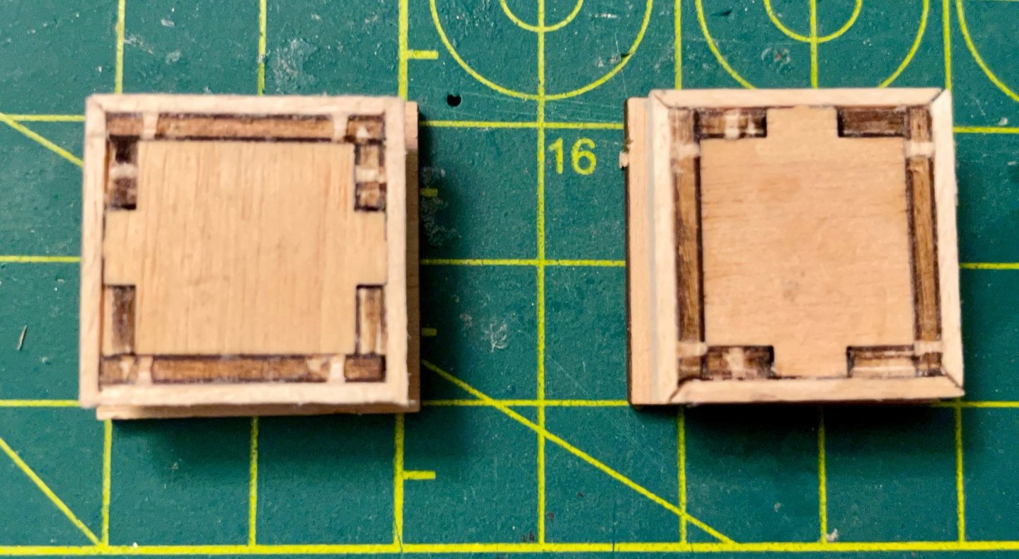
This morning, I finished seizing all of the blocks for the foremast yards. As I did so, I thought I might offer something of a tutorial on the technique I use for this. I'm an old Eagle Scout and a leader now that my son is in Scouting, so I feel particularly confident when it comes to tying knots. I don't think that my technique could be called authentic, but at the scale we work at, I think it's mostly indistinguishable and is more accessible to beginners. For a more authentic common whipping knot, check out J Brent's video tutorial. The key difference in appearance is that the trimmed tails of the knot are more visible with my approach, since they are perpendicular to the rope being seized, while the common whipping knot leaves them parallel. But, on to the explanation... Frank Mastini writes that "Seizing is a complicated and exacting craft, especially on a model. And intricate seizing is not something at which a beginner should try his hand. We'll keep it simple: When I say 'seize it,' I mean use a simple overhand knot, a few wraps, and a dab of glue" (Ship Modeling Simplified, 77–78). On my first kit, I started with that explanation and some video tutorials. The results were usually bulky and always inconsistent. As a quick example, two seized deadeyes from that first kit; note how fat they are, the inconsistency of shape, and the inconsistency of position. Sure, I had no significant skills at that point, but the bigger problem was that I hadn't found a way to control my seizing knot. Over the next several kits, I gradually refined my technique into what I do now, which produces more consistent and well-controlled seizing knots. The first step is wrapping the line around the block, securing it with a drop of Dritz FrayCheck on each side, then clipping it into a clothespin while the glue dries. Once that's done, I cut a piece of sewing thread about 100mm long (I don't actually measure, but I think it's about that long). I lay the legs of the line across the thread and tie an overhand knot, pulling it up into the block as I tighten it. (Don't pull upward too soon or the block will pop out of the knot!) . . Next, I do a double wrap by crossing the two ends of the thread behind the legs. I just lift up the legs pull one end across and hold it down with a finger, then the other. This is where things can get a bit fiddly. If the thread has twisted (which often happens as I tie the knot), then the legs are likely to kick around a bit, sometimes flipping over. When this happens, I use my left ring finger to hold the legs in place both while I wrap the ends with tweezers and while I tie the second overhand knot. Again, I pull the knot up toward the block while tightening it. . . . Then, I repeat the steps for another double wrap and a third overhand knot. . . If the seizing has slipped away from the block, I gently pull the legs in opposite directions, to slide it up as close to the block as possible. Then, I trim the ends of the thread and apply a drop of FrayCheck to glue the seizing in place. The final product features five wraps, with the multiple overhand knots helping to control the thread at each step. With practice, this goes fairly quickly and easily. In about an hour, I seized ten blocks for the foremast yards, two for the finished lifeboat, and one that I had to replace on the foremast top. (The last three aren't shown here.) I hope this helps others out!


-
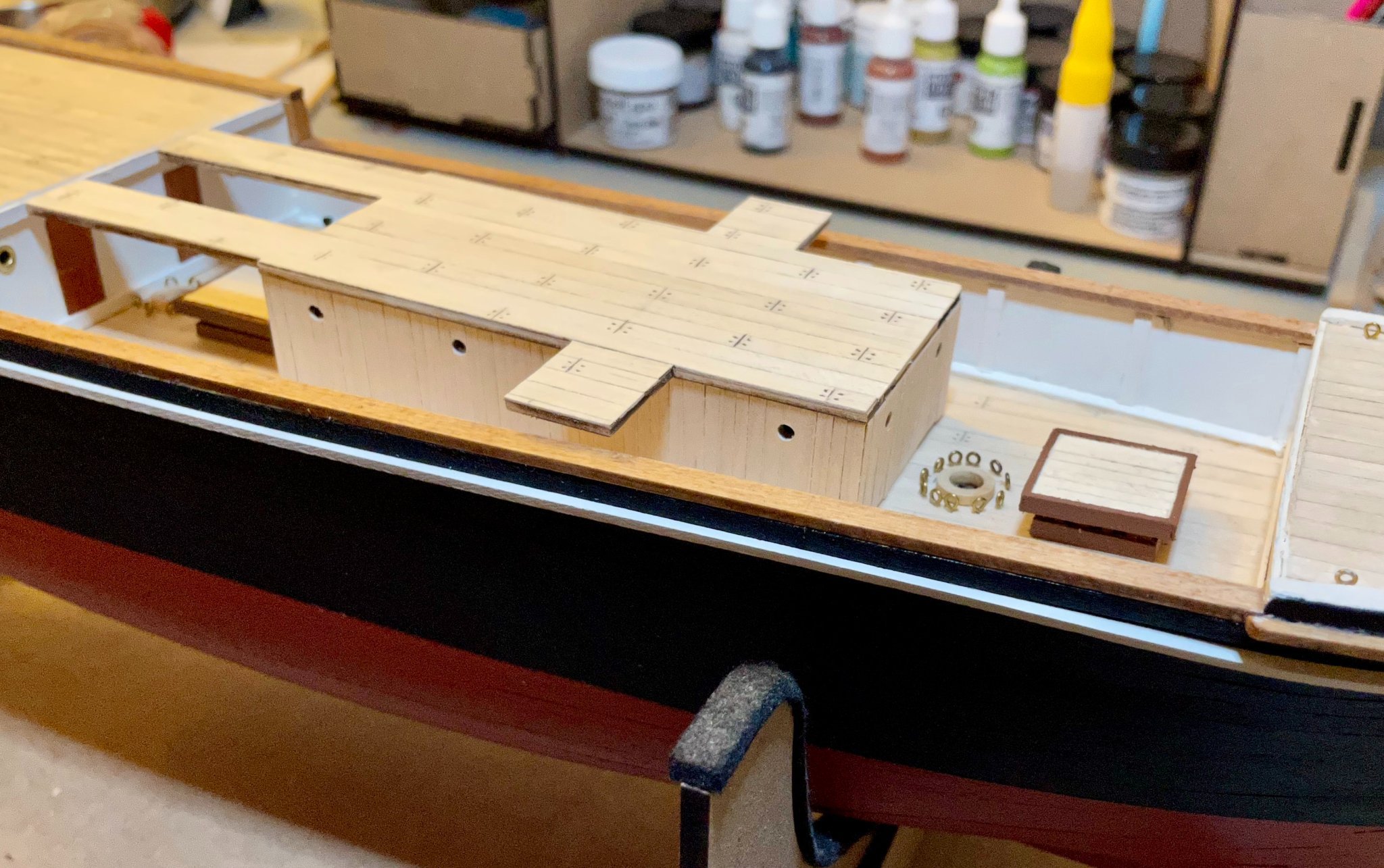
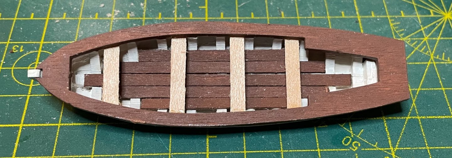
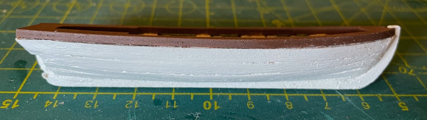
Two nights ago, when I wrote that I was debating whether or not to plank the mast top, I suppose my unconscious mind had already made the decision. Regardless, as I sat there looking at it yesterday, I knew it had to change. Since the instructions don't indicate to do this, I went back to Frank Mastini's book for advice. And here's the final product, with the last coat of paint drying on the trim! Last night, I finally got around to putting the last coat of stain on the floorboard planks of the first lifeboat. So, this morning, I was able to assemble it. It still needs finish and two blocks, but is otherwise ready to go. Planking these lifeboats was definitely the most challenging step and I did just okay on this one. The sheer of the gunwales is also something to pay attention to, though with eleven frames there's plenty of surface area for the glue. The second photo shows the better side, which is almost certain to be the outboard side once it's hung on the davits. One thought looking ahead. Both Johnny and I have expressed our preferences for hanging the midships lifeboats inboard. But the lifeboat davits that come with the kit don't make that easy. The pegs at the bottom fit nicely around the rubbing strip and will allow for secure installation in some shallow drilled-out holes. Right now, I see three options to put the lifeboats on the inboard side of the davits: 1) Alter the davits by rotating the top or moving the pegs to the other side; 2) Place the lifeboats on cradles, but leave the davits facing outboard; or 3) Replace them. As far as the first solution, I'm a bit reluctant to experiment, since I'm afraid of messing them up or making them unusable. The third solution is a definite possibility, though I need to do more research; in the cursory search I did, I didn't find anything that struck me as being quite right. The second solution seems the simplest to me. In a number of photos, the midships lifeboats were on cradles with one davit turned inboard and the other turned outboard supporting the gangway. I'm not sure how weird it would be to have the boats inboard and all davits turned outboard. I'm definitely open to suggestions and brainstorming here. I won't be installing these until the rigging is done, so I have lots of time.
-
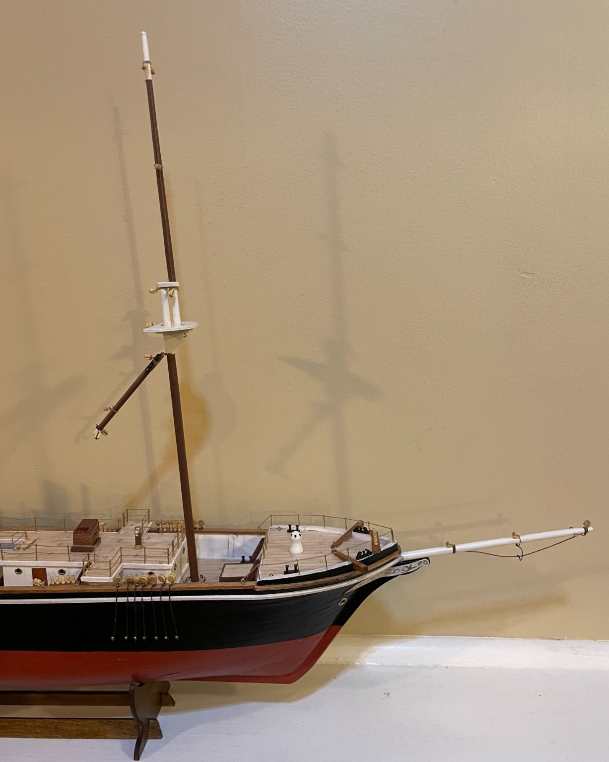
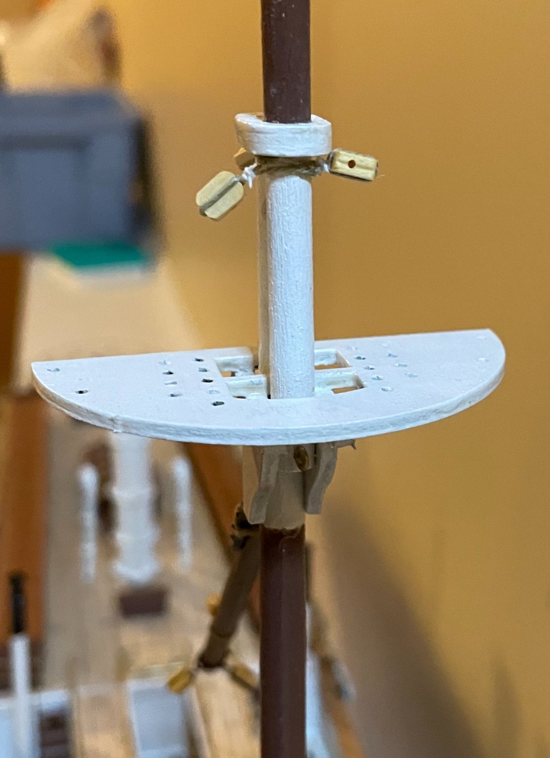
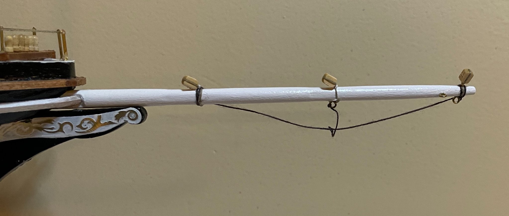
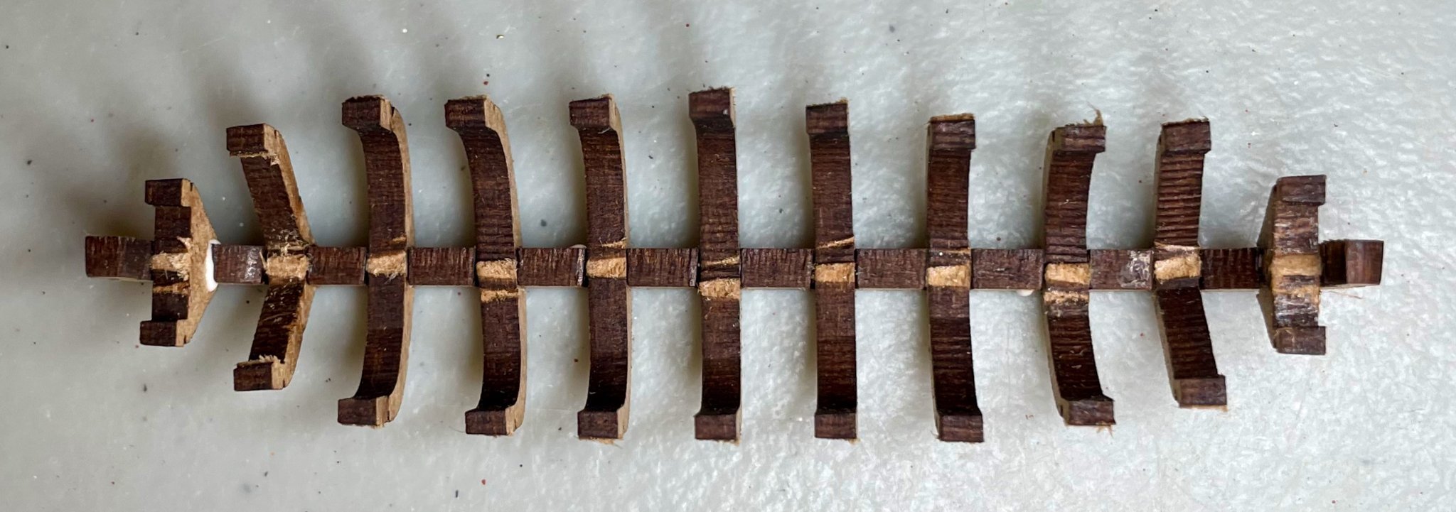
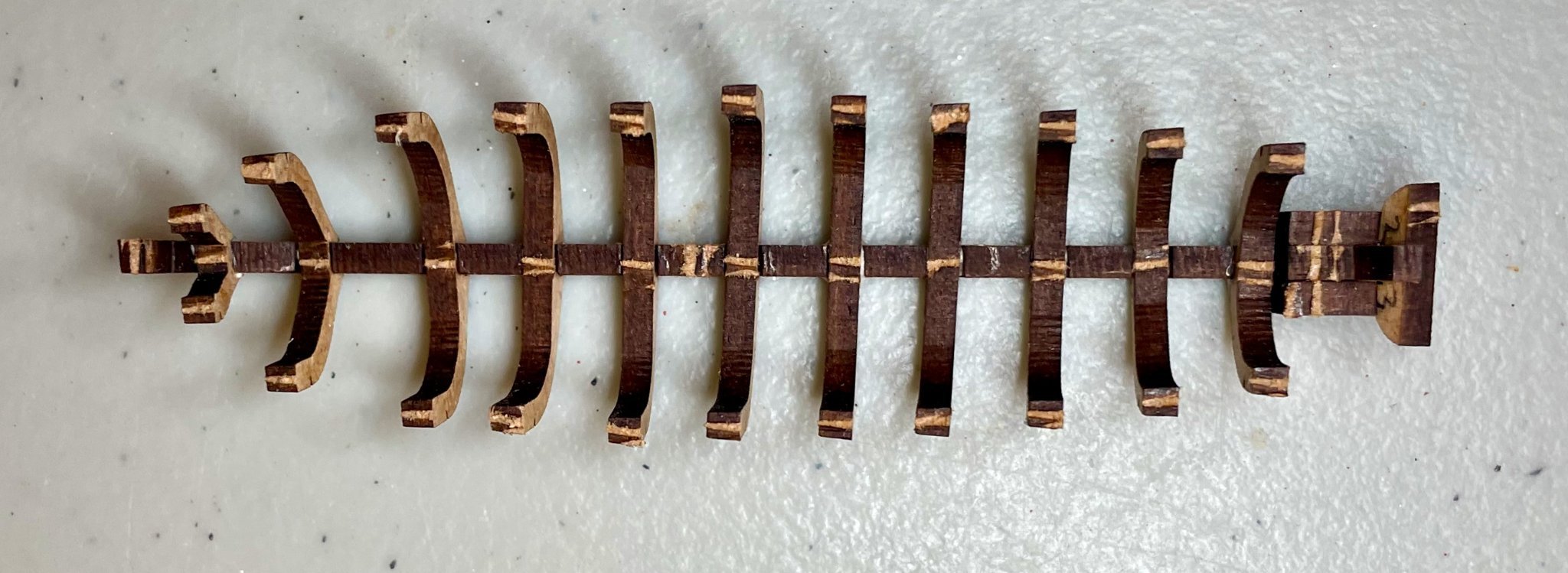
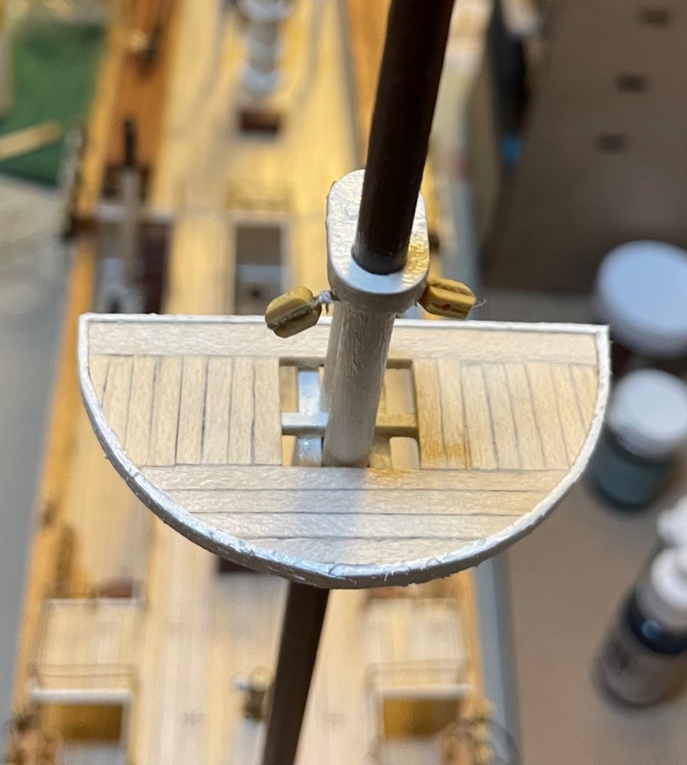
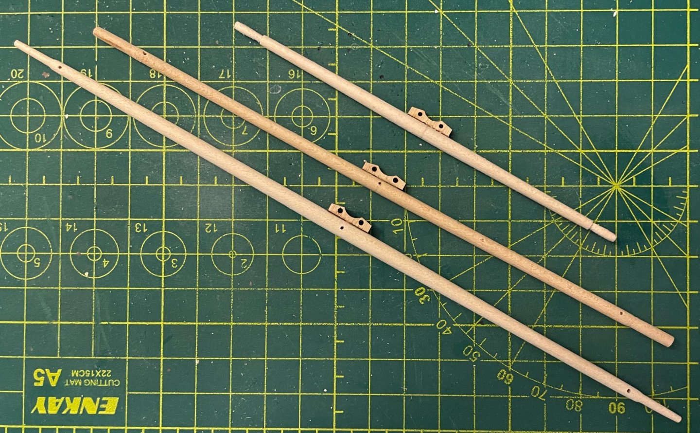
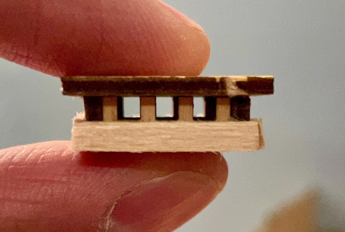
Thanks, Johnny and Bob! And thanks all for the views and likes! Johnny, your point about tying on the foremast and, especially, the mainmast rigging is well taken. I think I'll do that after fashioning the masts, so I have a clear idea of just how much thread I really need. I've been continuing to work this week, making progress on the bowsprit and the foremast. Since I had already cut and shaped the bowsprit while installing the rub rails, progress there was pretty quick. I just needed to paint, then prepare and install three blocks, four eyebolts, and the foot rope. This isn't installed yet, so no worries that it's not seated correctly. Next up was the foremast. In order to keep from getting very similar looking parts confused, I'm preparing, building, and painting one mast at a time. This represents another big step up for me, as it's the first ship I've built with topmasts. Shaping the masts went pretty smoothly. Each of the masts is topped with a 3mm glass bead. The beads in the kit are pretty inconsistently made—most are fine, but some are misshapen, some are thicker than the rest, and a couple of them are actually two beads fused. It's no problem finding three good ones for the masts, but I may need to hit the craft store before I need the rest of them. The real interest is the area around the top and crosstrees. The cheeks and top are precut plywood pieces, as is the cap. For the moment, I've built this per the instructions...but I keep looking at the top and I'm just not satisfied with its look, so I'm considering sanding off the finish and the paint so that I can plank it. The gaff is just kind of hanging there for now. OcCre has really simplified the rigging of the gaff sails, so this is a place where more experienced buildings have an opportunity to upgrade the kit. At the mast end, there is a metal bracket into which a hook is installed (a piece of 1mm wire bent at a 90º angle). The hook is inserted into an eyebolt on the mast. There are no jaws or parrels, and the gaff cannot be hoisted into place. There are also no booms for the fore gaffsail or the main gaffsail. (The mizzen gaffsail does have a boom.) You may also note in the first photo above that I've tied down the backstays on the foremast deadeyes, on the starboard side at least. When I do the port side, I'll take some photos of my process, but for now will just note that I ran a piece of thread as a temporary shroud so that I could determine the correct angles. Another new thing for me is rigging square sails. With the Endurance's barkentine rig, only the foremast has square sails. I have mostly finished shaping the three yards. Nothing too exciting here, just a lot of patient sanding since I don't have a lathe. The foresail yard definitely turned out the best. The upper topsail yard is okay, but I'm going to go back and try to smooth out the yardarms. The lower topsail yard (middle) is a bit strange to me; that one tapers differently than the other two and the yardarms are significantly thicker. This is in accordance with the plans, but I'm wondering if that might be a mistake or poor drawings. I'd be curious for thoughts on this from the more experienced builders...is it more normal for the yards to all have the same shaping or is this typical? Next steps: finish up the yards and start preparing their blocks. Also make a final decision on whether or not to plank the top.


-
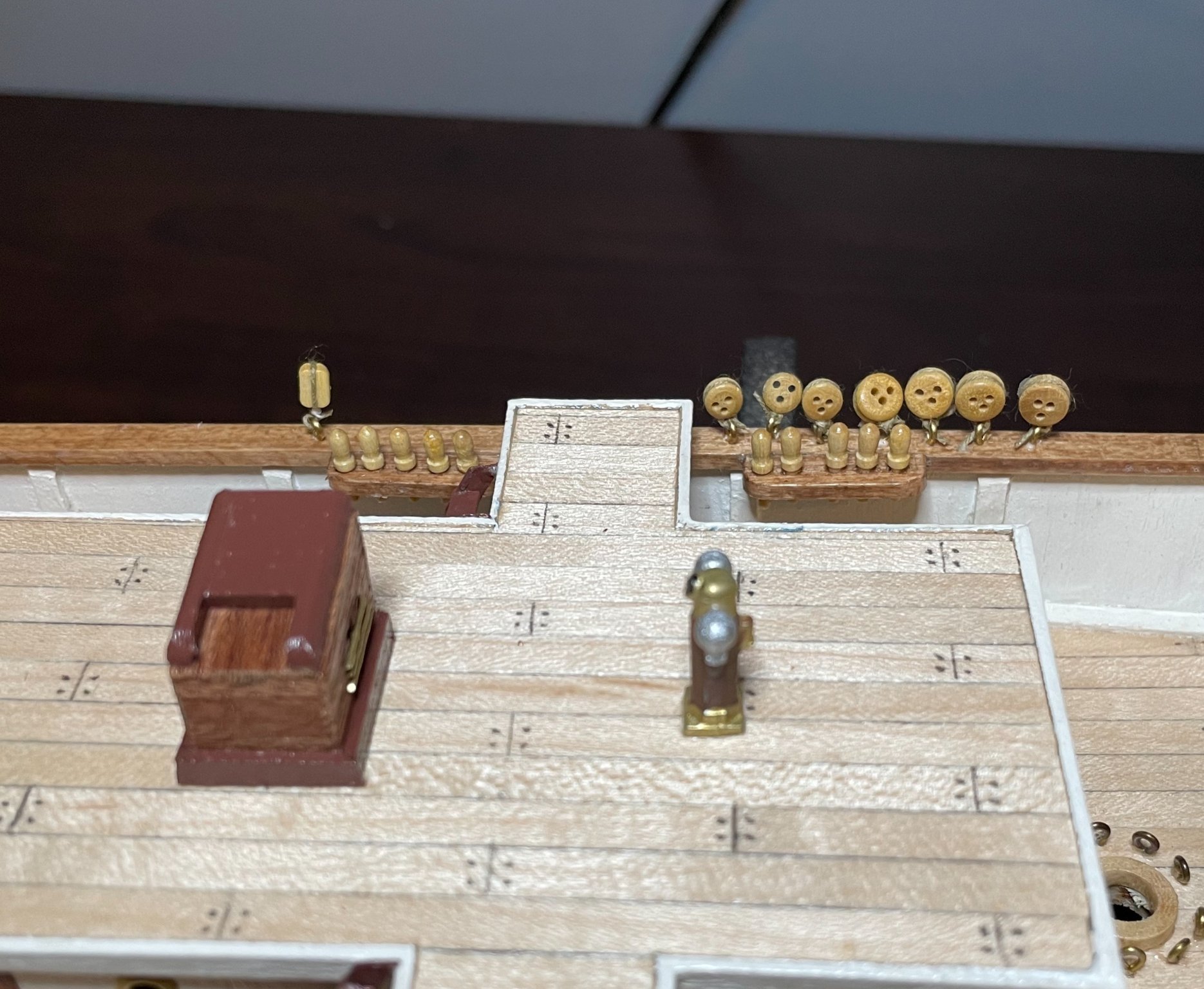
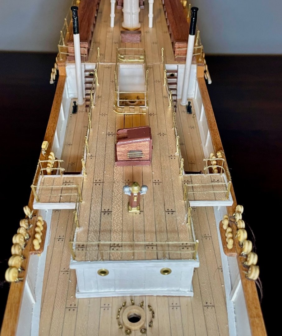
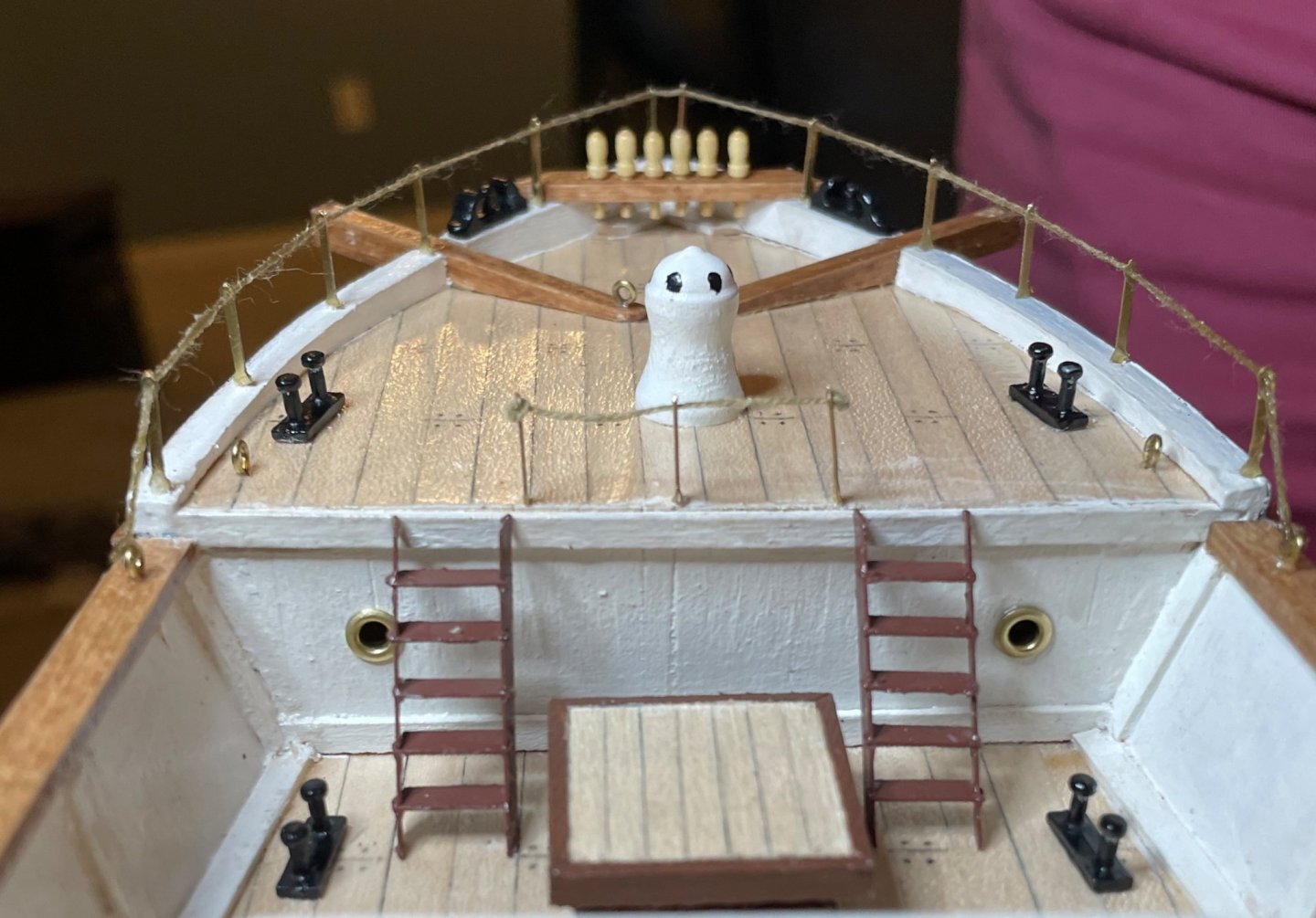
Yesterday evening and today, I devoted a lot of time to the Endurance over several work sessions, and am thrilled with the progress. I got into a groove on the railings and they started to go pretty quickly—especially after getting a helpful tip from Constitution to switch from CA glue to nail polish. For threading, I found nail polish far superior to CA glue because it adhered to the thread more compactly (medium CA glue may have been the culprit) and it was much less messy. I'm still getting some of the CA glue off my fingers! The focus was on the bridge, quarter, and aft decks. It was essential to plan the order carefully: first the railings around the gap between the walkways, then the ones that run from one staircase to the other, then the forward side of the bridge deck, then sides of the quarterdeck, and finally the aft deck. This is a different order than the instructions had, but it was the one that made the most sense to me. For knots, I used a double overhand, which offered enough bulk to not get pulled through the holes, while still being small enough to reasonably approximate the scale. (A couple knots were sloppy and a bit too large, but they're mostly fine.) It's not very clear in the second photo, but I made one small adjustment for the two stanchions closest to the forward bulkhead on the aftdeck. In the plans, those are to be inserted parallel to the bulkhead, with enough space for the knots (but not really enough space to tie a knot!). I rotated those so they are perpendicular to the bulkhead, with the knot on the in-board side. It's a small adjustment, but allowed me to get those two stanchions almost flush against the bulkhead. One other note is that I dabbed FrayStop along the entire length of the threads, not just on the knots. This stiffened the thread a bit, but I was also surprised to discover that it condensed the thread a bit, pulling up some of the slack in the lines. Since I was on a roll and it was still mid-afternoon, I also finished up the remaining deadeyes. The pre-shaped holes in the channels weren't big enough, so I opened them up a bit with a 1.0mm drill bit. As mentioned before, I wasn't satisfied with the wire strops I was able to make, so I took the safe back-up plan, using .5mm brown thread per the instructions. At the moment, the threads are just dangling from the channels (and from the forward mast's deadeyes). These will eventually be secured to brass pins, but I'm going to wait on that until I have a better understanding of the angle that's needed. I've now finished the deck fittings and lower rigging, except for the anchors, davits, and lifeboats. Although I'll continue puttering along on the lifeboats, all of that will need to wait until the rigging is run. So, it's on to building masts and spars! But in the meantime, here are a couple shots of the overall impression at this stage. Thanks for the encouragement, tips, and suggestions so far! Please keep them coming...I'm feeling pretty intimidated by the rigging, quite a bit of which runs into some tight spaces. For example, the seven eyebolts in that gap between the quarter-deck-to-bridge-deck walkways!
-
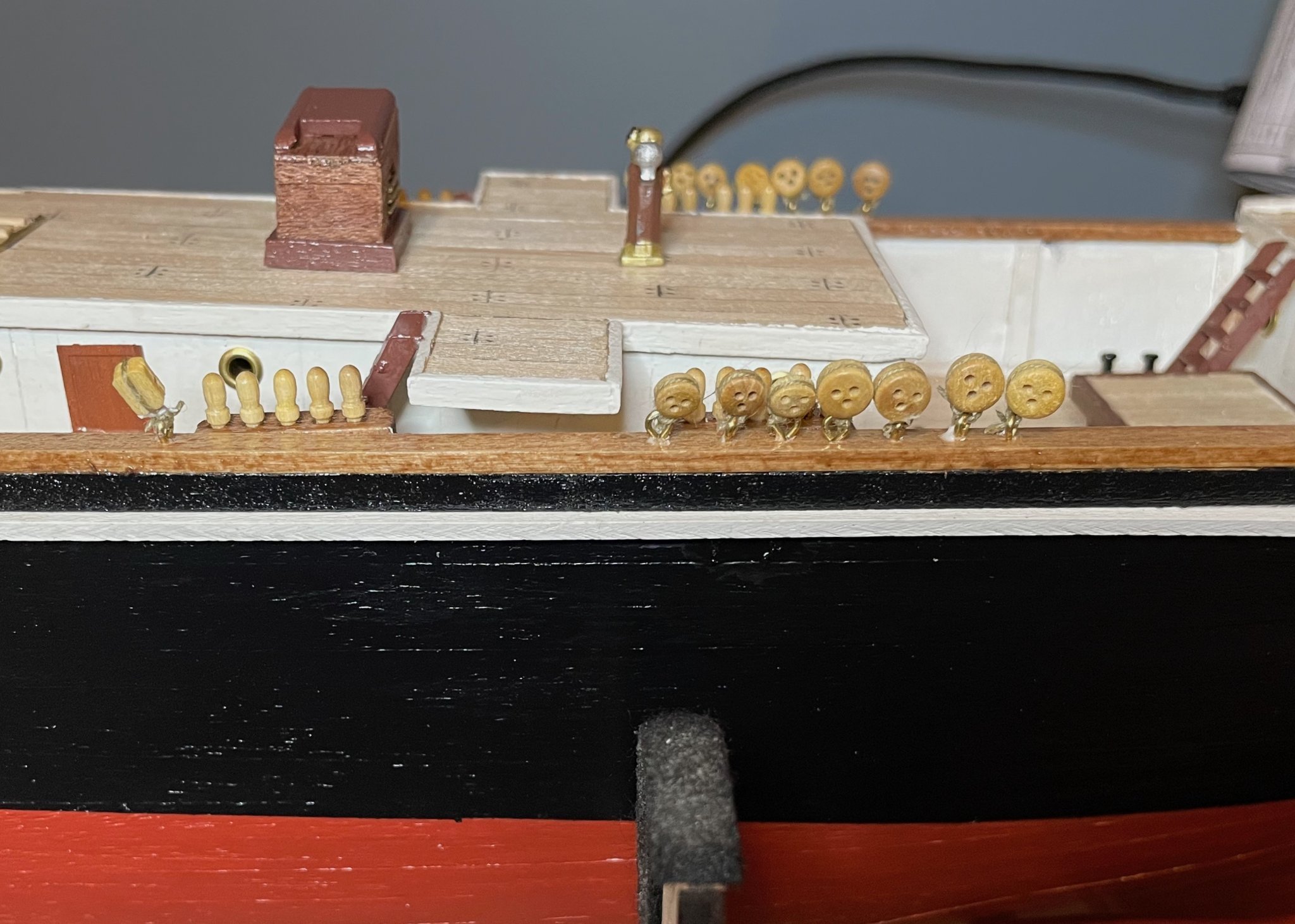
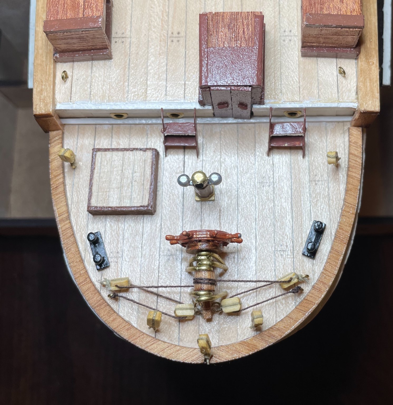
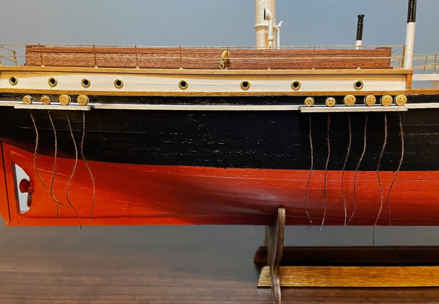
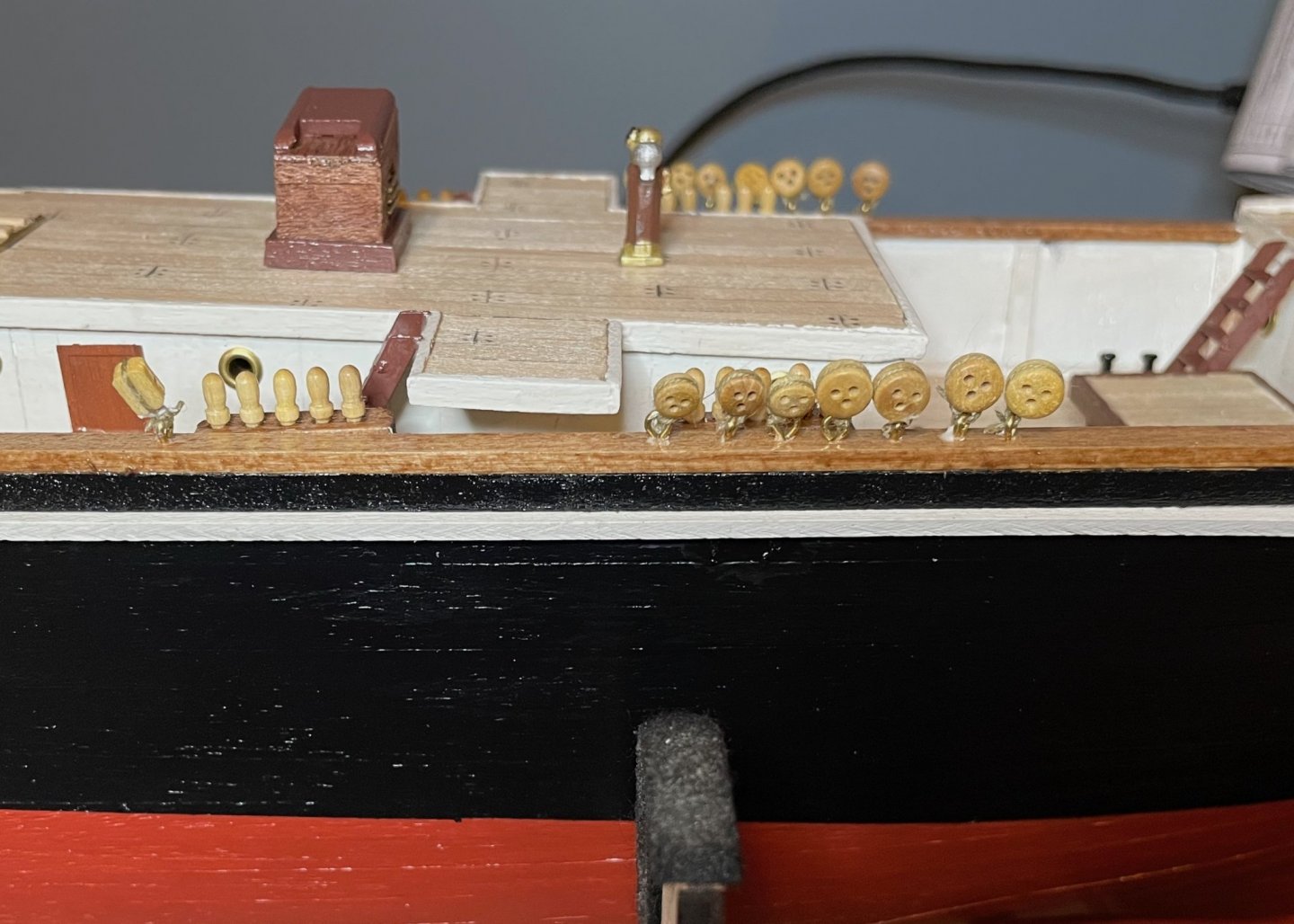
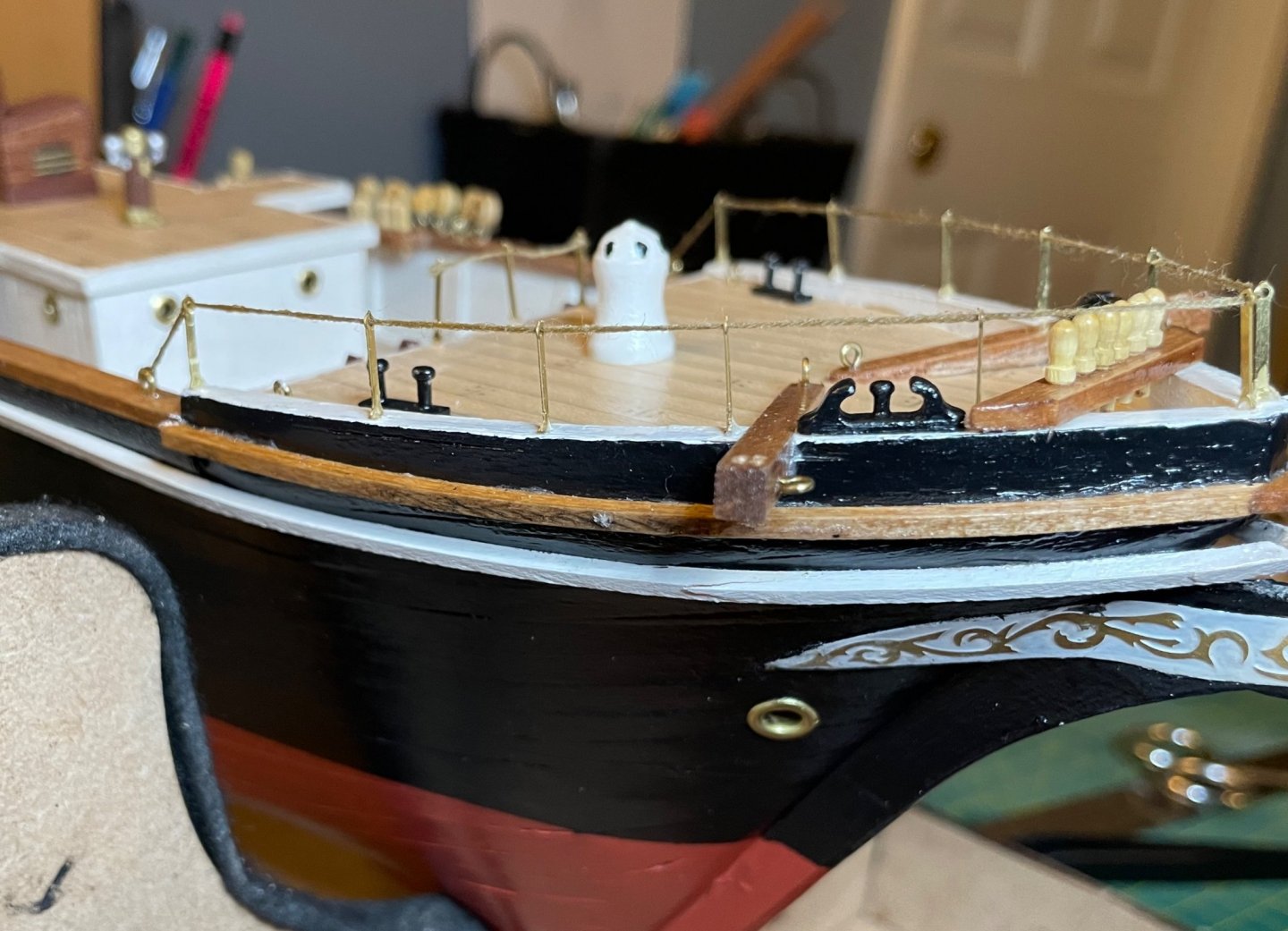
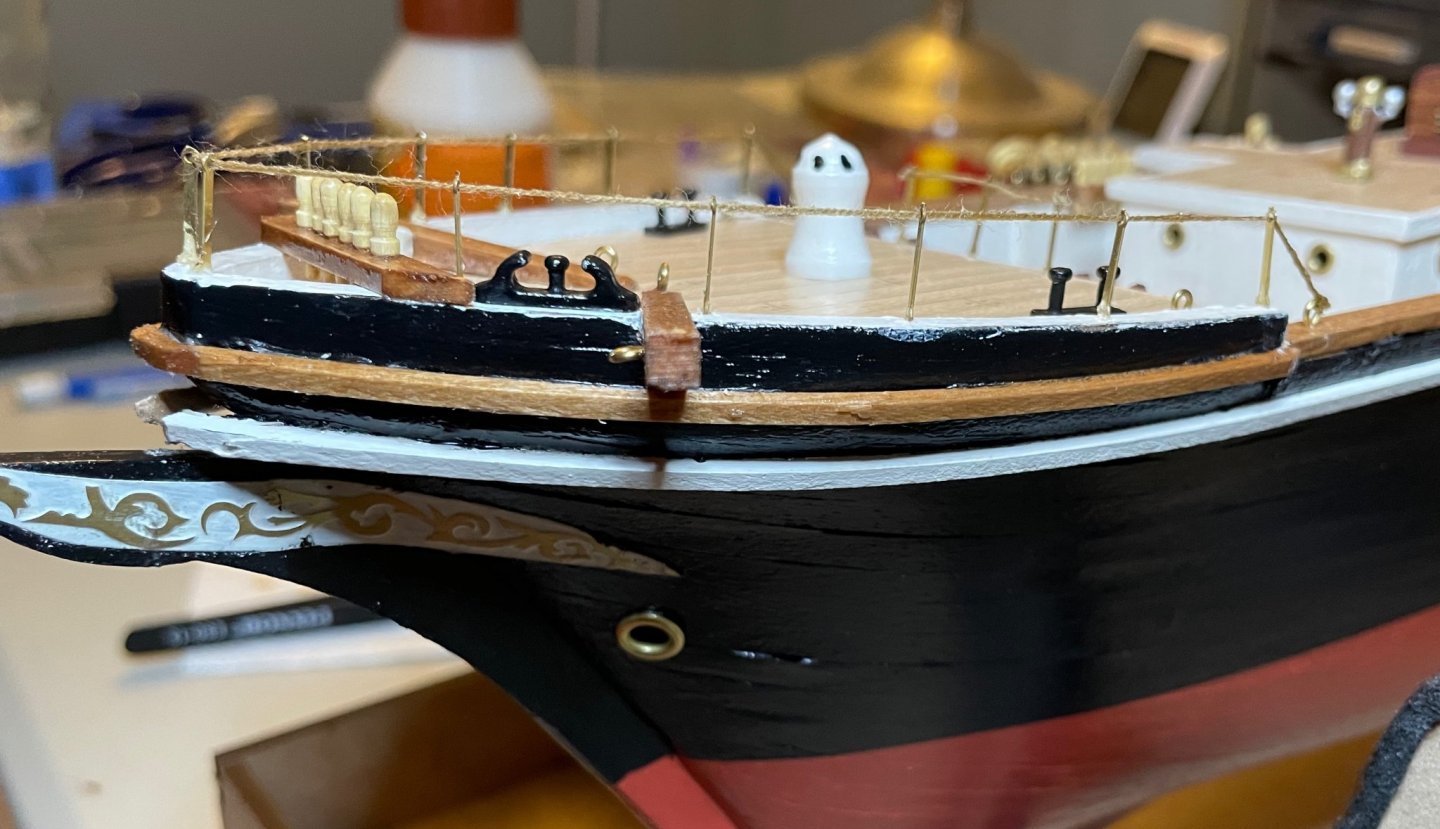
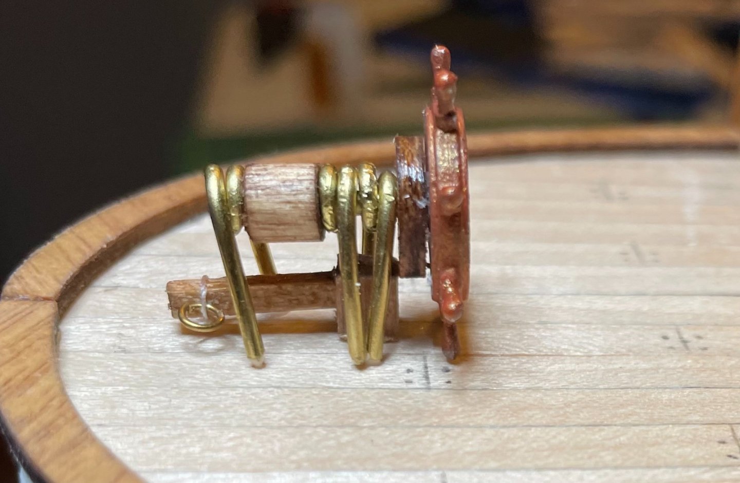
Keith, thanks again for the advice on using wire around the deadeyes. In the end, I experimented a bit, but just couldn't fashion something that satisfied me. So, I decided to go with the safe back-up plan, the instructions per OcCre. When I build my next kit, I'm planning for something smaller and simpler, so I can really work on developing some of my techniques. I've added this kind of wire-work to my notes for that future kit. In the meantime, some updates on the progress. First, I rigged the steering gear. While I'm pretty pleased with how this turned out, it really highlights how far out-of-scale the blocks are! The "chain" (.5mm brown thread) runs from an eyebolt, through two blocks, around the barrel, through two more eyebolts, and ends at an eyebolt on the other side. Also of note...I have some doubts about the placement of the block on the stern rails; it's positioned per the plans, but surely will interfere with the railings once they're installed. Next, I've installed a pair of blocks and the deadeyes for the forward mast. The thickness of the hull is a great advantage here as you can safely drill deep holes for the eyebolts. There will eventually be some .5mm brown thread used to simulate the iron backstays on the original ship, but I'm waiting to do that until I can better picture the angle at which they'll need to be installed. Finally, I've installed the railings around the forecastle. You can see I started with the railing between the two staircases...I didn't get quite enough tension on that one. But I'm pretty happy with how the railing around the edge looks! As Johnny has noted, the stanchions here are flat and a challenge to work with. After a bit of experimentation, I found it worked well to drill a shallow .8mm hole and to apply a bit of CA glue to hold them in place. They are mostly sturdy, though I was pretty delicate pulling the thread through. The holes can't be much larger in diameter in the thread; I dabbed a bit of CA glue on the end, which made it a lot easier to thread through the holes. Next steps: Install the remaining railings, then install the remaining deadeyes.


-
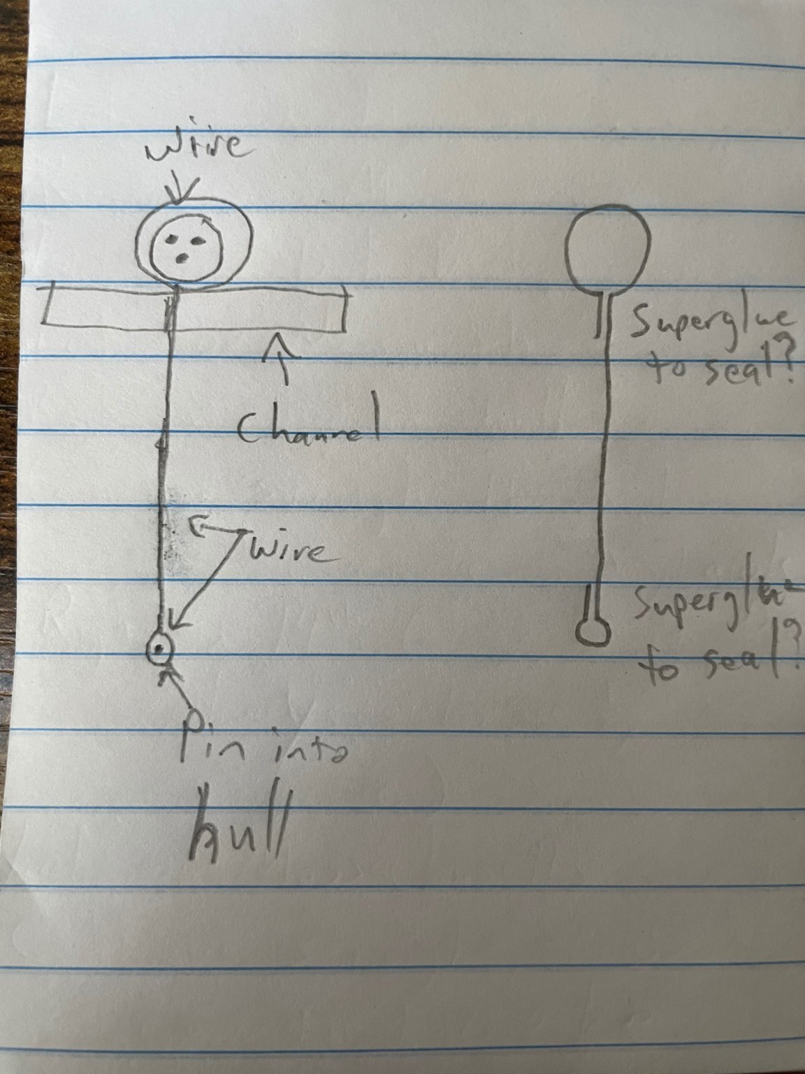
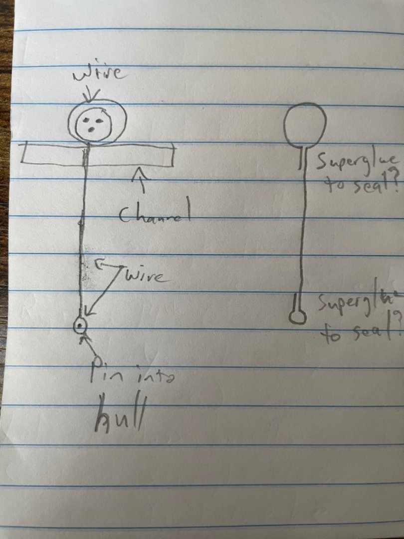
Thanks, Mike! This is only my fifth kit and I've always left them au naturel because I can't figure out a good way of painting/staining them without making a huge mess. That's my plan for Endurance, too, though I know it's not a historically accurate look. Thanks, Keith! I appreciate the suggestion and am seriously considering that advice for the deadeyes. Do you have recommendations for good examples of how to form the deadeye strops and backstays out of wire? There must be some on MSW, but I'm not turning up anything that quite matches the look of the Endurance. After studying the photos again (especially this one), I'm game to try doing wire on the deadeyes. But I'm not sure how to solve two problems: a) wrapping the deadeye securely, so it doesn't pull open the wire loop once the shrouds are under tension; and b) attaching the end of the backstay to the hull. In the plans, OcCre calls for using .5mm brown thread; that's a safe back-up plan that is well within my skill set. I have lots of 1mm wire, though I'm not sure if that would be too heavy. I also have no skills or equipment for soldering. I've drawn up a quick sketch of a possible solution, but I'm not sure yet how effective this would be.
-
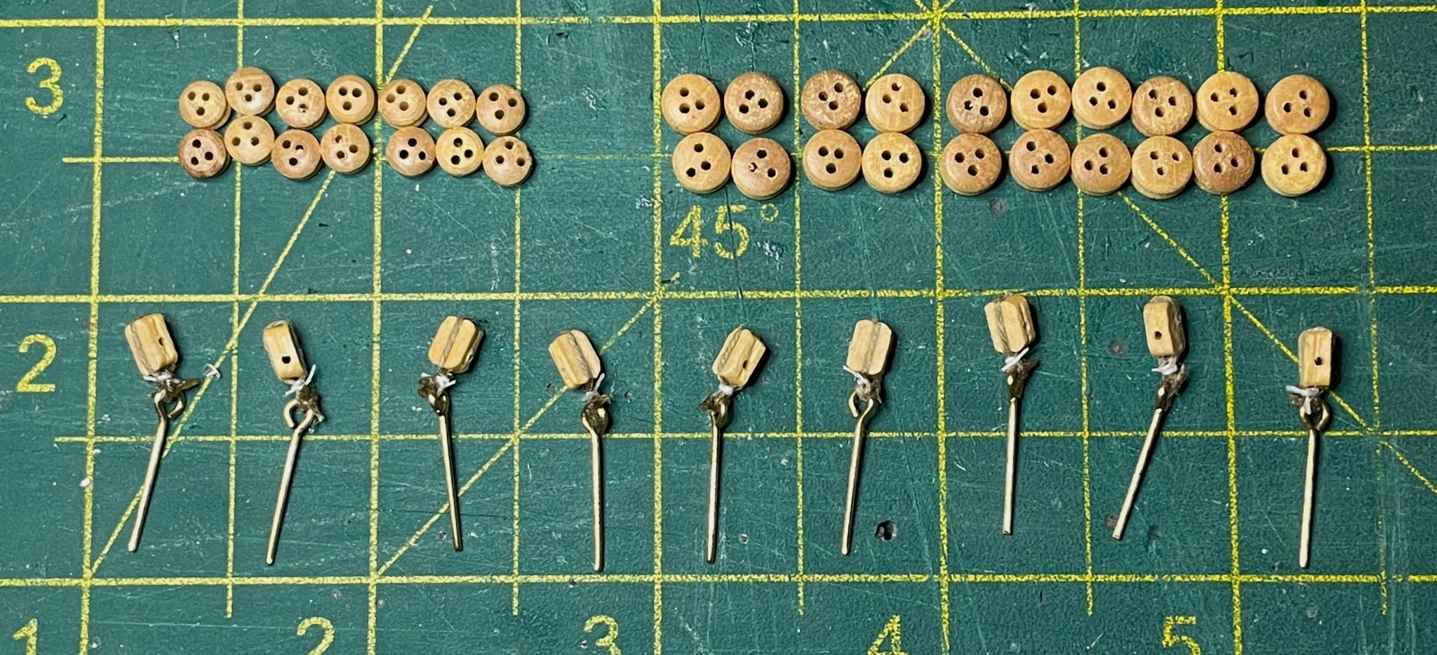
The finish is drying on the Endurance and wood filler is setting up on the first lifeboat. So, I decided to start prepping the lower rigging. There are nine single-sheave blocks attached to the deck, fourteen small deadeyes, and twenty large deadeyes. I'm using the ones that came in the kit, which are of significantly higher quality and consistency than what I've seen in my previous kits. I finished up the blocks tonight, but will get to the deadeyes over the next several days. My routine on the blocks is to first wrap the .15mm thread around each block, applying a dot of FrayStop to each side to glue it into place. Next, I seized the blocks with a piece of thin white sewing thread and dotted the knot with FrayStop. Then, I trimmed the white thread and tied the blocks onto eyebolts and dotted the knot with FrayStop. Finally, I trimmed the ends of the .15mm thread and used one last dot of FrayStop to keep the loose ends in check.
-
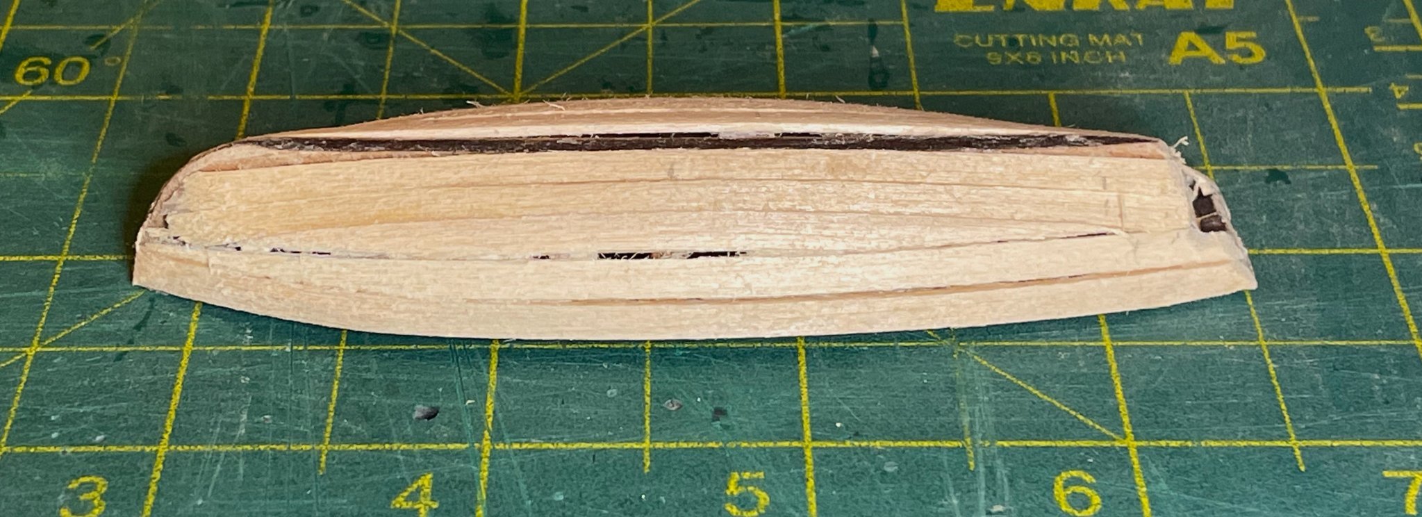
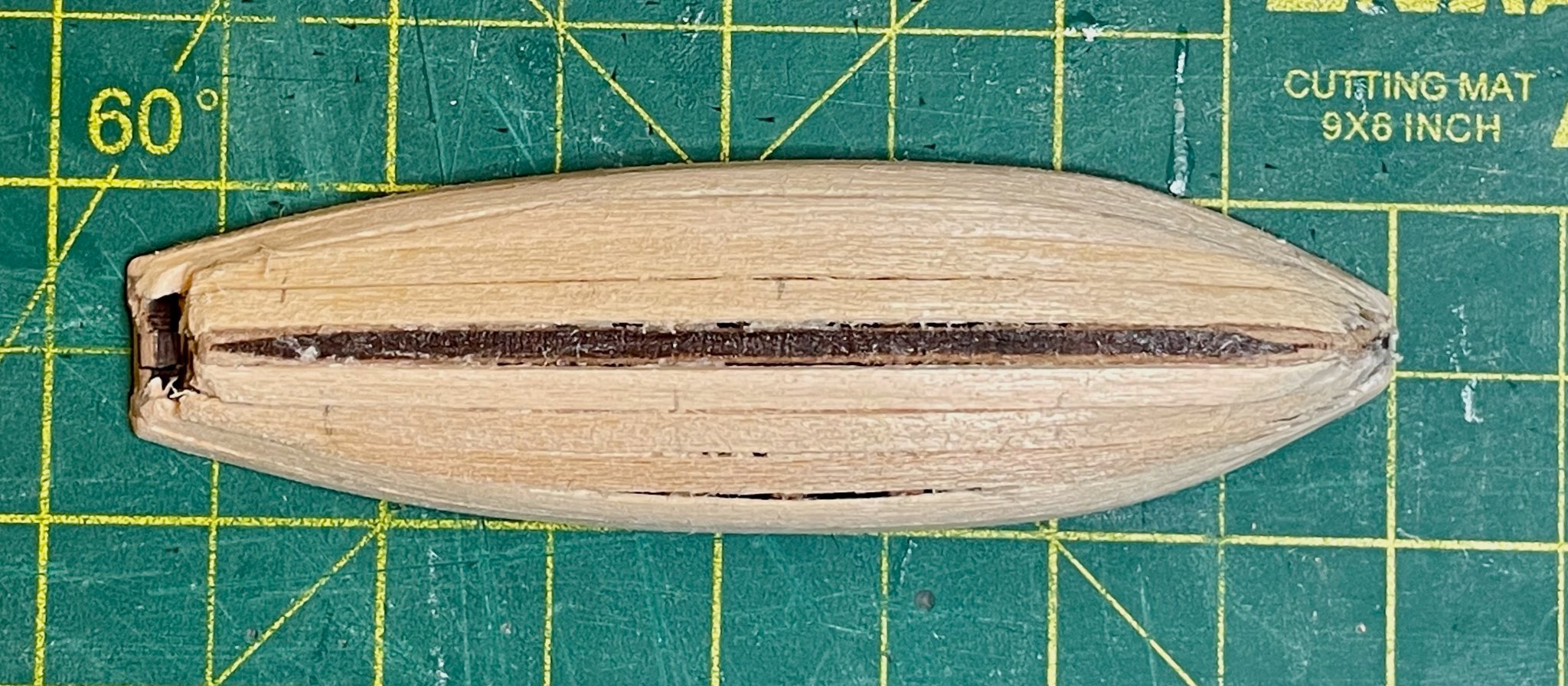
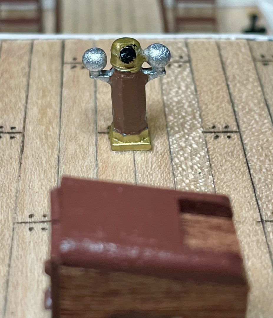
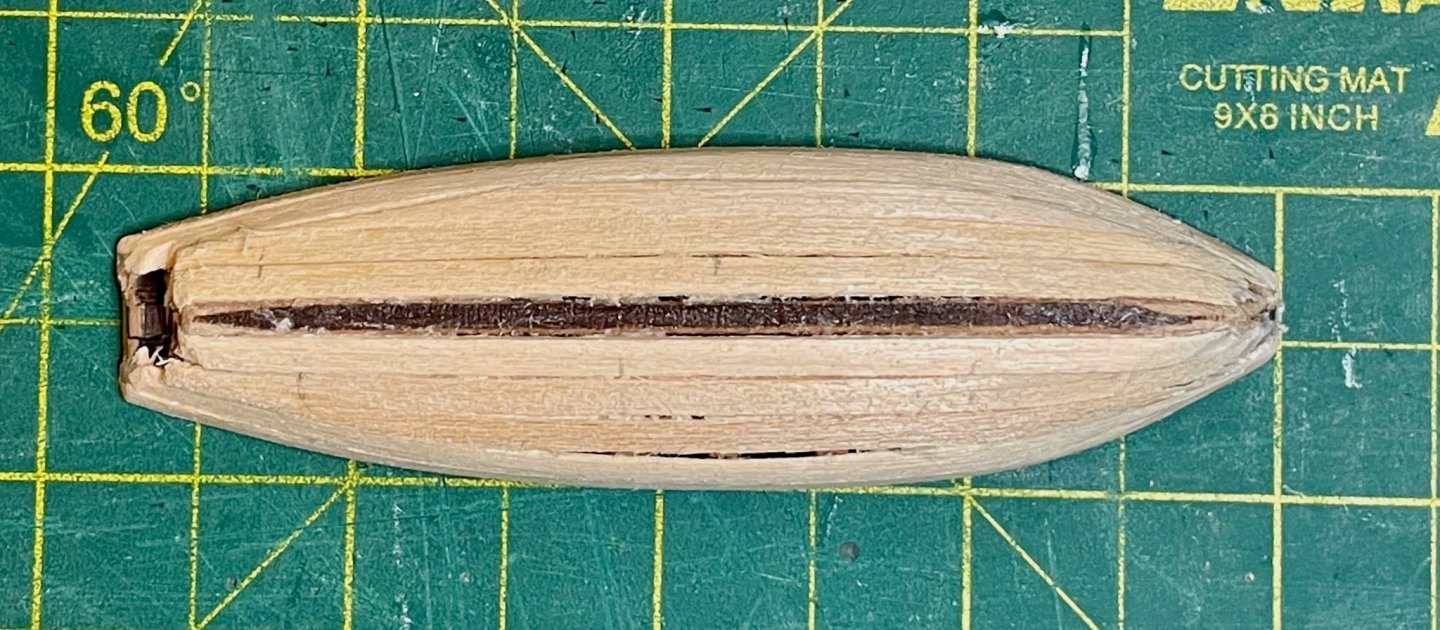
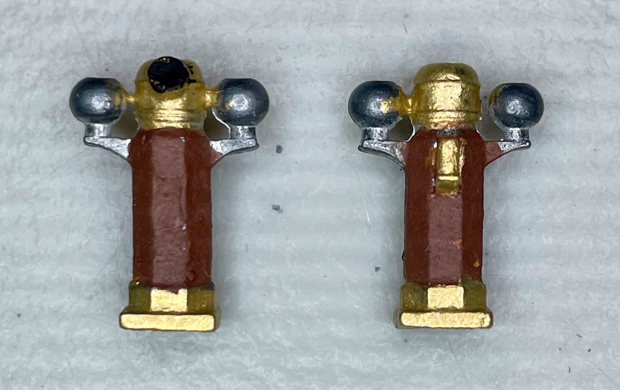
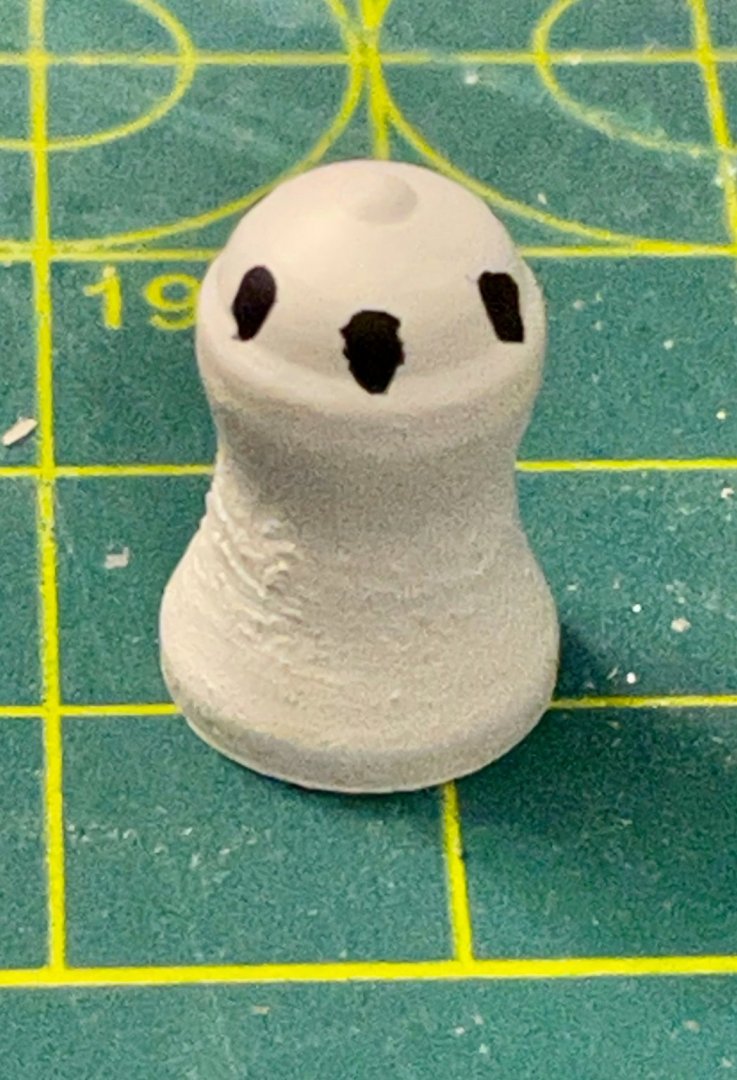
Thanks for the likes everybody and for the very kind comments, Johnny! I've been applying satin finish lately and I'm really liking how things are looking. For now, two quick updates. First, a quick shot of one of the finished binnacles, with silver paint on the Kelvin balls. I've also managed to finish planking the hull of one lifeboat. For me, I think that this has been the most challenging part of the kit so far; I suspect this will be the breaking point for some novice builders. Twice, I had to pull planks off, the second time pulling everything off (6 planks) and starting over from the bare frames. A note on the challenges and the solutions that ended up working for me. First, the size and shape are pretty awkward in terms of clamping. I tried spring clamps, clothespins, and tightly rigged rubber bands. (The limit of my clamp selection for now.) Second, given the small size, the shaping of the planks wasn't easy, particularly where twists were needed. Third, because of the first two challenges, I found my usual PVA/wood glue to be useless. After picking up a fresh bottle of CA glue, I finally had success by using a brush applicator and then holding the planks in place until the glue was set. It's a medium CA glue, so I just popped on a TV show and took my time (10 planks in 3 episodes). In the end, I think it looks better than it has any right to, though it's definitely going to need some wood filler for the gaps. Hopefully my practice on this one will make the others that much better. Next steps: For the Endurance, finish applying satin finish to the decks. For the lifeboats, apply wood filler to seal the gaps on the first boat, then install the stempost and keel.
-
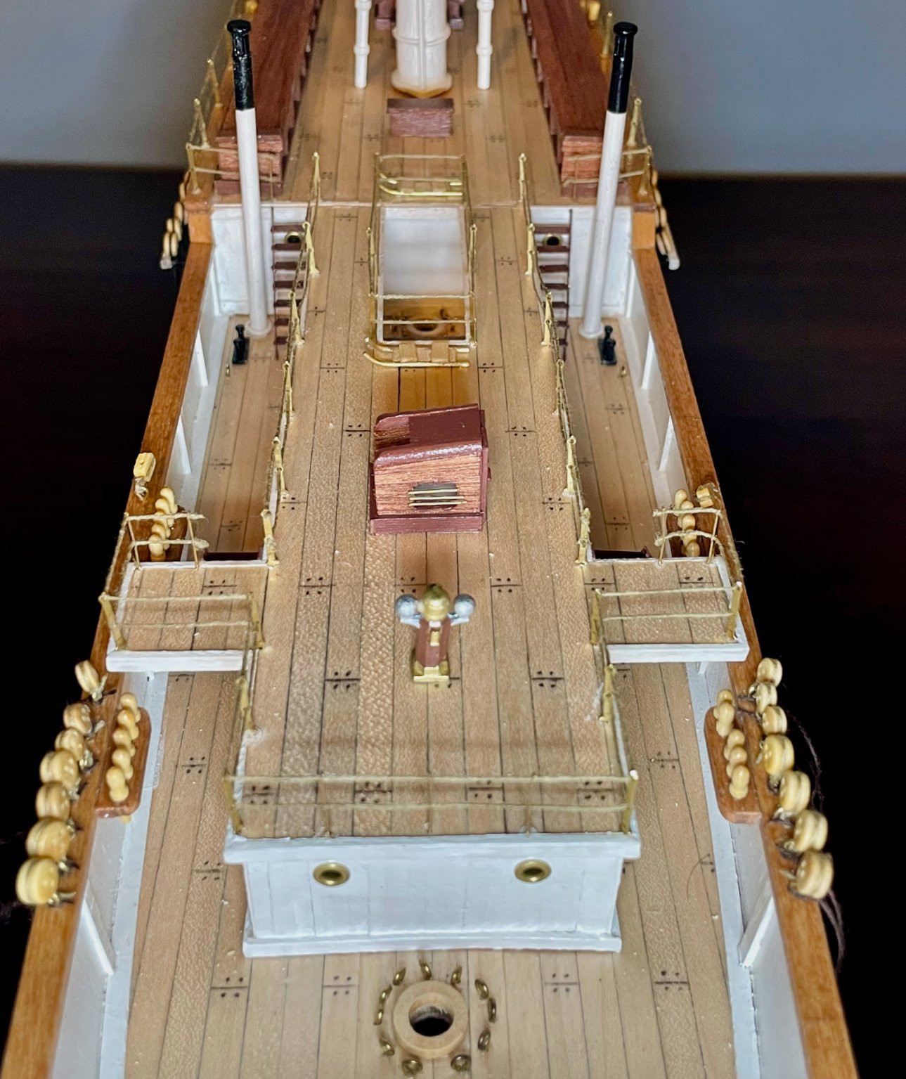
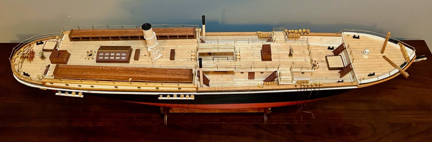
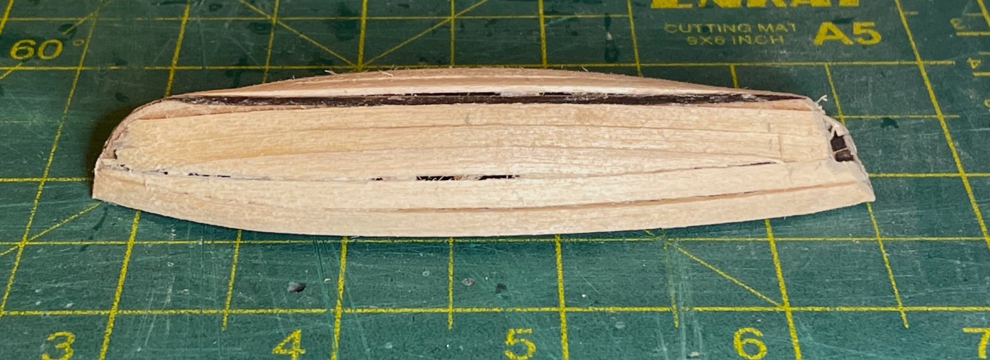
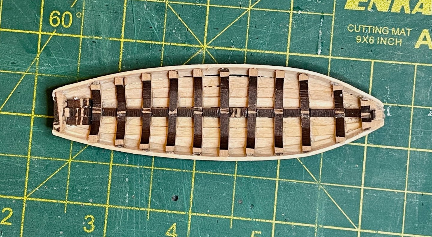
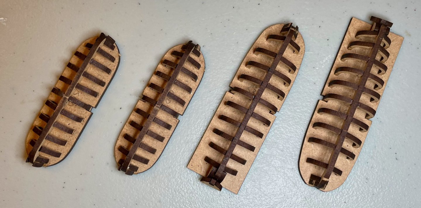
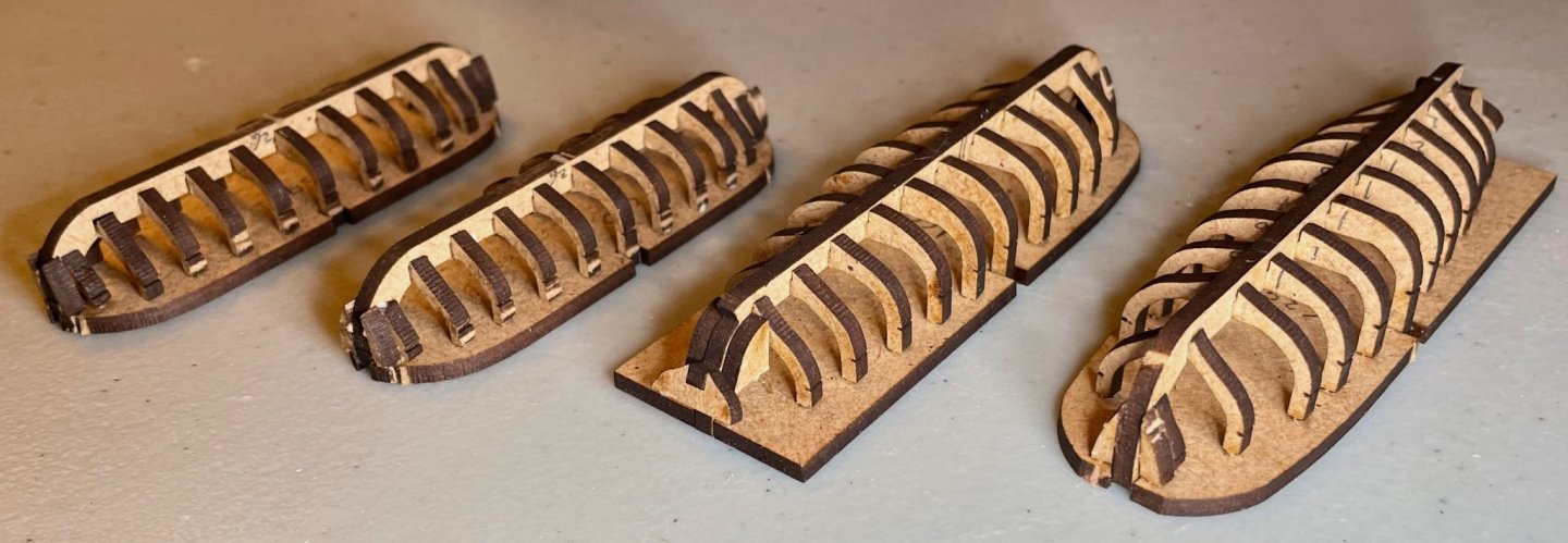
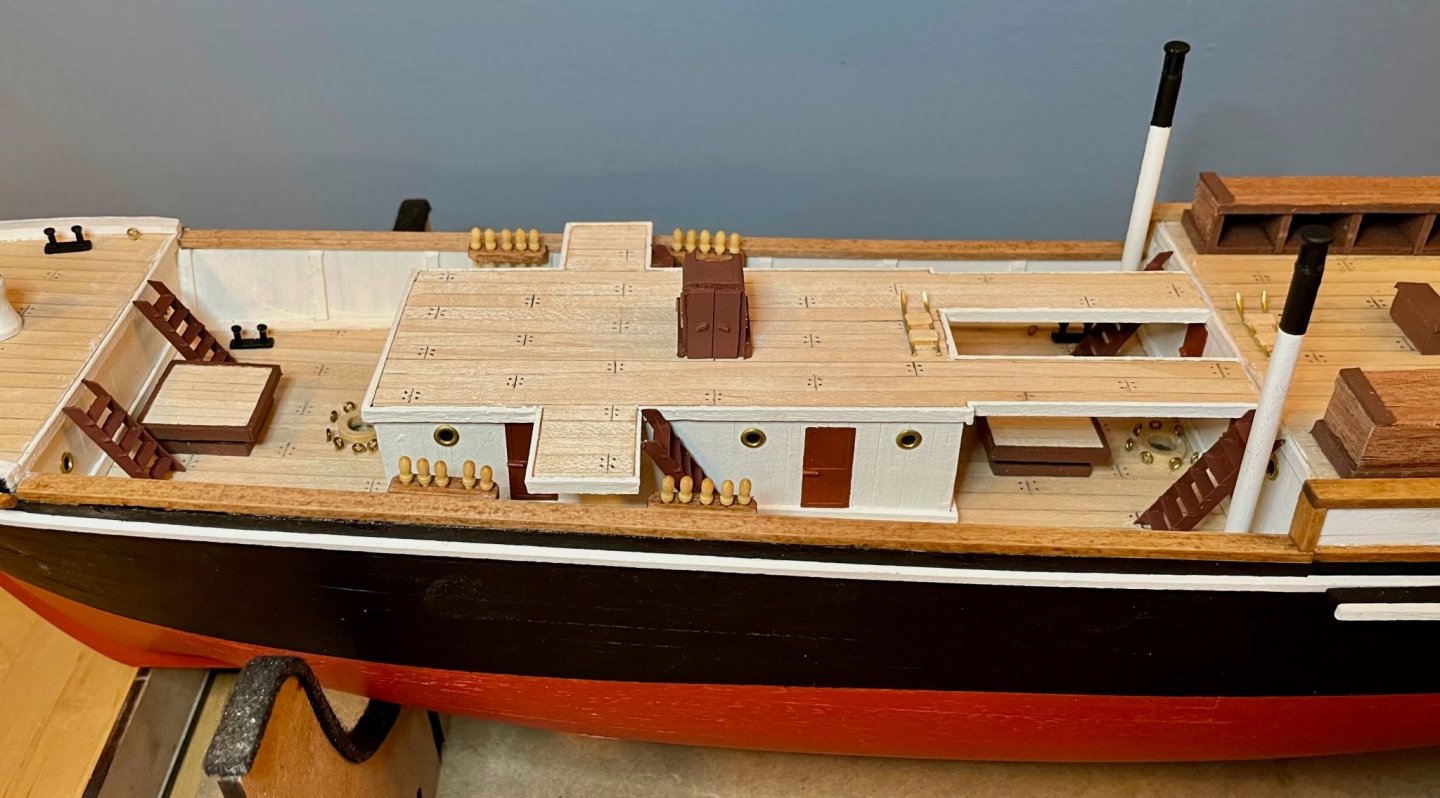
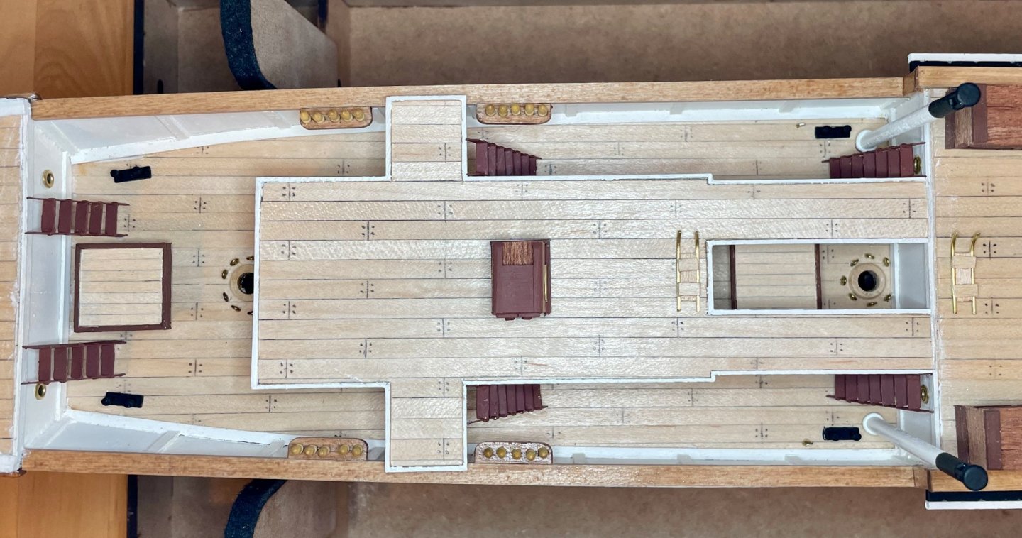
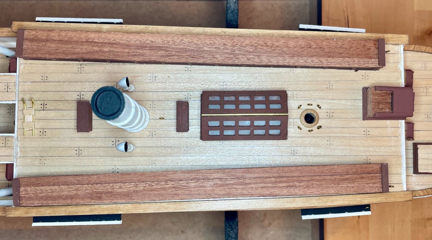
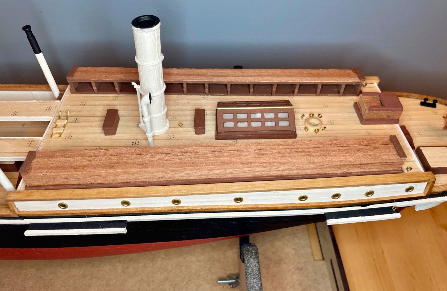
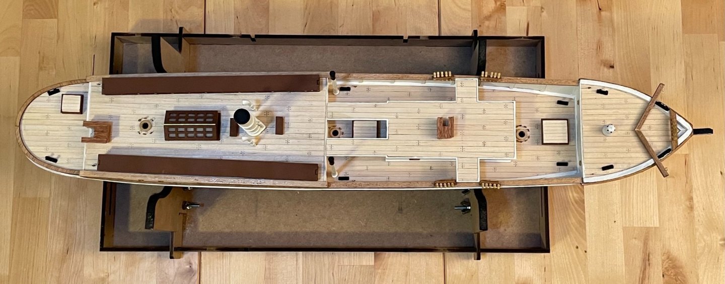
A big photo dump tonight, after spending more time working on the Endurance today than I probably should have. The deck fittings are now all but complete and installed. All that remains are the binnacles, the railings, and the lower parts of the rigging. I'm holding off on the latter two until I apply finish to everything, so that I'm not applying finish to cotton thread. Not sure if that would actually be a problem or not, but something doesn't click right in my head with that. I'm mostly done painting the binnacles, just waiting on some silver paint to arrive in the mail. My paint scheme is primarily inspired by this photograph, in which you can see the bridge-deck binnacle in full sun. There are several other good views of the same binnacle with varying degrees of shadow: 1, 2, 3, and 4. The colors of the Kelvin balls were a big question for me. The kit calls for a traditional paint scheme with one red and the other green. But the photo in full sun suggests that they were actually painted the same color. In photos 2 and 4 above, they look as though they may have been painted white, but the photo in full sun makes them look a little more metallic. So, these will be silver, once the paint comes in. The rest relies on typical colors/materials of that era: brass for the hood, base, and whatever instrument is on the side; wood for the pillar. Apart from the binnacles, here are some glamor shots of the deck fittings. First, the overall impression: A close-up of the foredeck. I did end up angling the catheads, as well as putting a little bit of a gap between them. Profile and overhead shots of the main deck. I haven't yet glued in the two smaller smokestacks/vents/whatever they are. The spacing will be tight when I install the railings, so I will pull them out when I do that. Profile and overhead shots of the quarter deck. The plans call for lining the sides and back of the dog kennels, but not the top; I didn't like the look of that, so went ahead and added some strips of sapelli on top, too. The 12mm dowel for the smokestack is a bit of an issue, at least in my kit. I probably could have sanded a bit more, but the bigger problem was that the wood was really thirsty and the ridges formed as it absorbed primer and paint. You can see the platforms to which shrouds will eventually run. The black portions are pre-cut pieces with notches for the shrouds and deadeyes; I haven't run into this kind of feature in my previous builds, but the design seems pretty slick and was easy to build. And profile and overhead shots of the aftdeck. . Since I'm in a little bit of a holding pattern while I wait for the silver paint to arrive, I started working on the lifeboats this evening. The keel and frames are made of laser-cut MDF. As with the rest of the laser-cut pieces, OcCre has done a really nice job here, making for quick work. The frames fit into the keel with no sanding at all. They were a little loose, though; you'll note in the first two photos that I wasn't able to effectively straighten them until they were mounted on the bases. I would also note that a few pieces have burrs in really unfortunate locations: this is particularly true of the small (tiny!) filler blocks and the keels of the two smaller boats. For the most part, the rest of the burrs will be sanded off when I fair the hulls. . . Next steps: Things are about to really slow down. After I finish the binnacles and apply finish, the focus turns to the lower rigging and the railings. With 84 posts, those railings will take a while. As for the lifeboats, the next step is fairing the hulls.


-
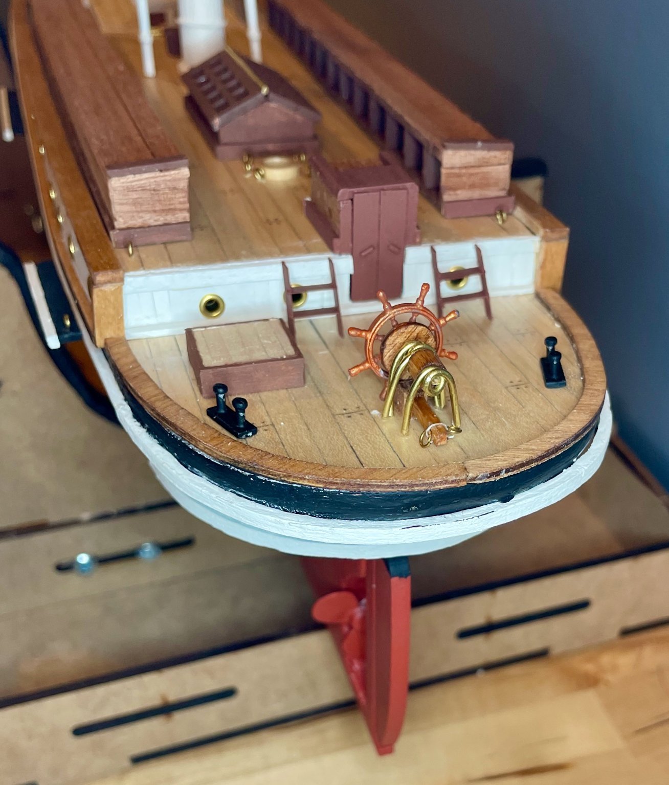
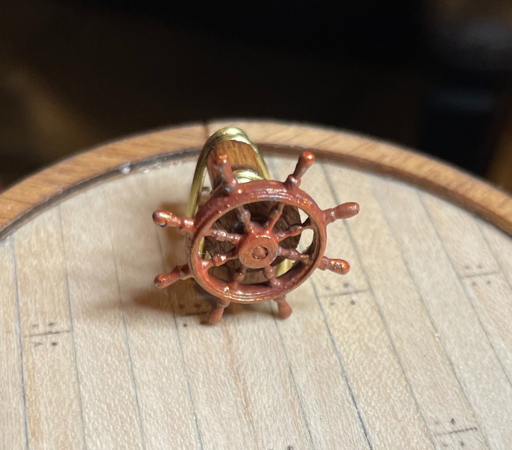
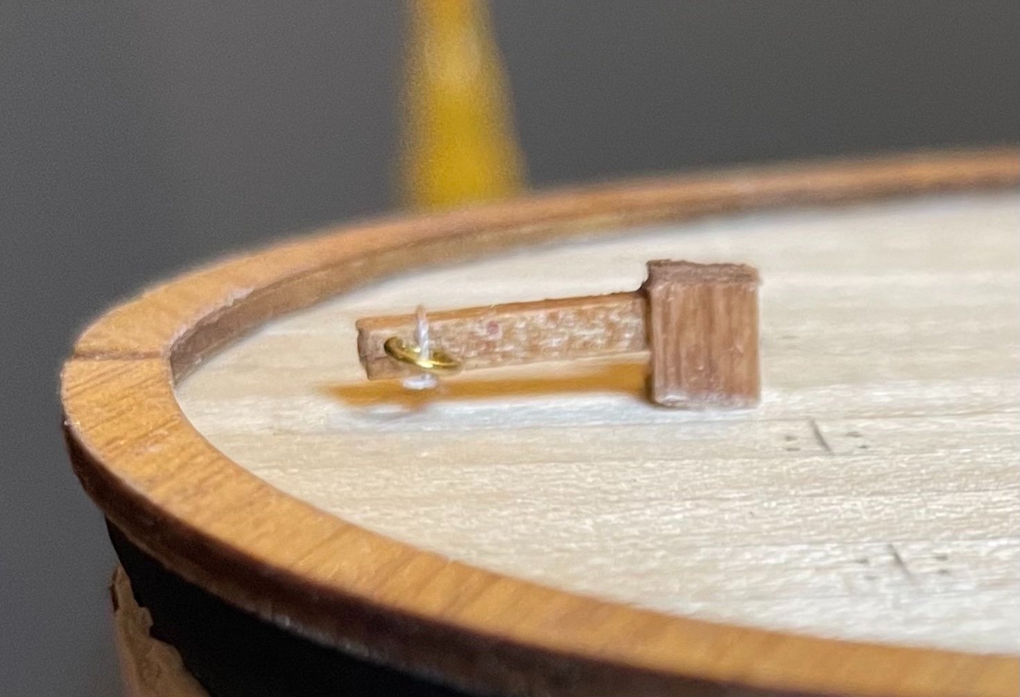
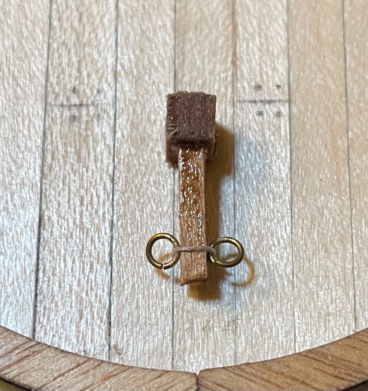
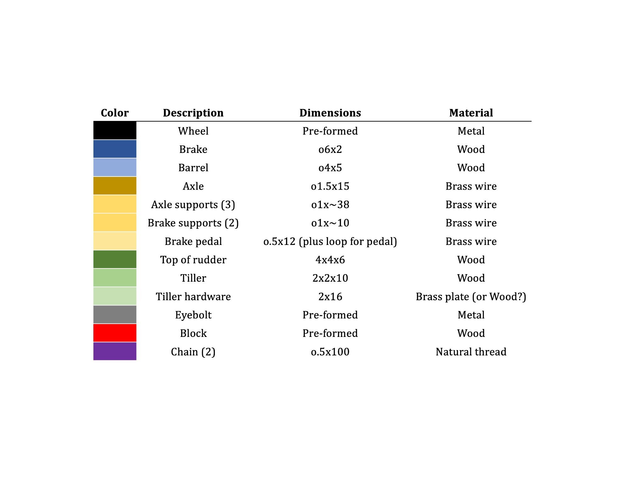
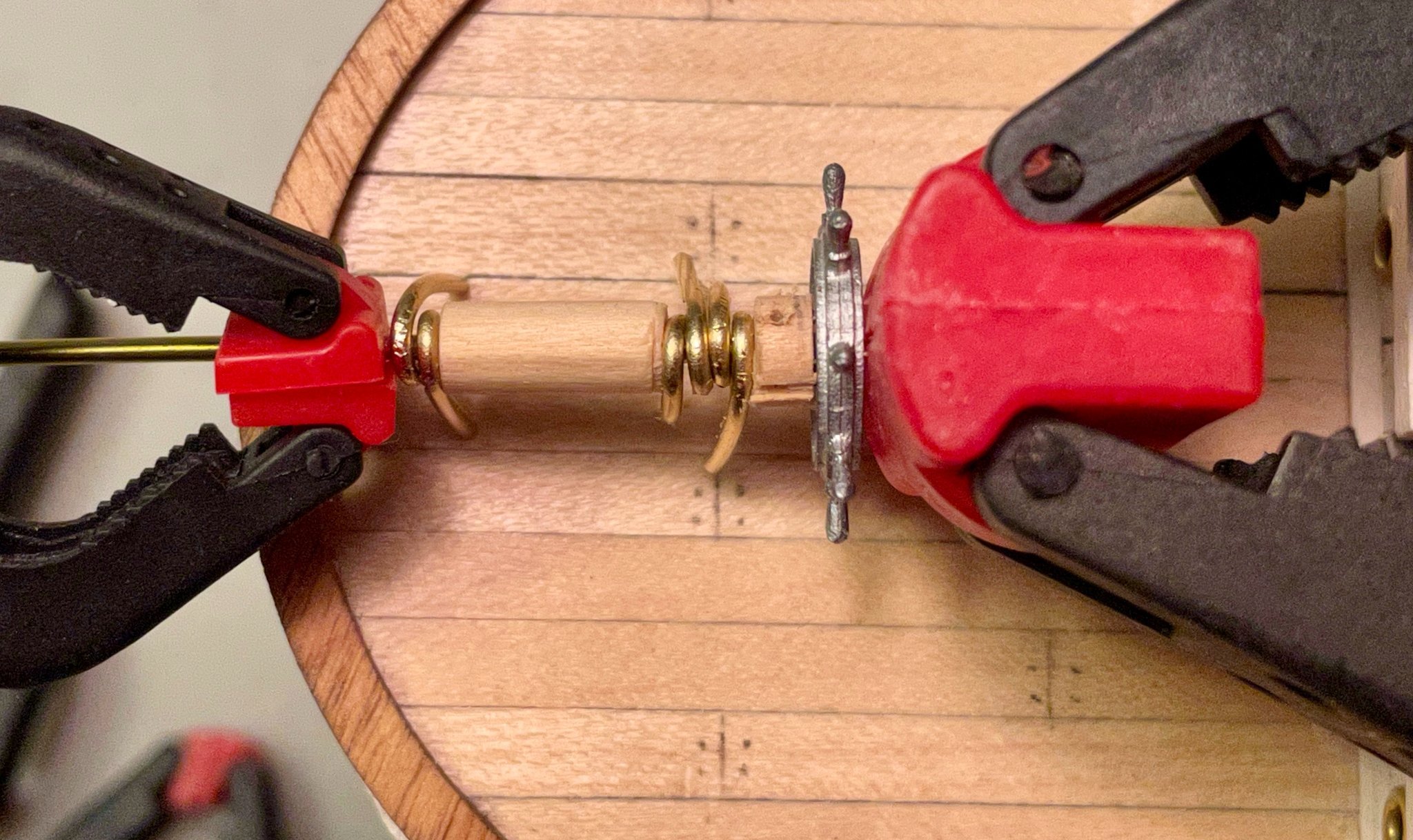
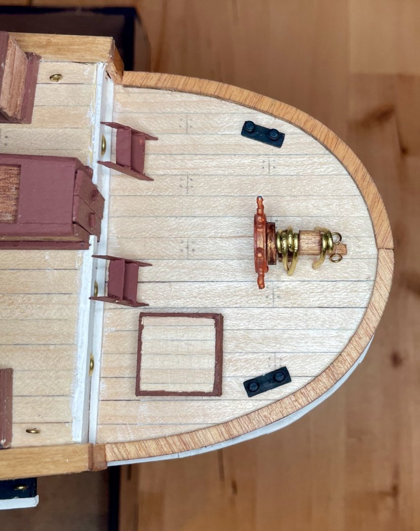
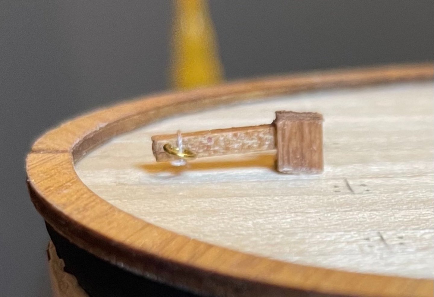
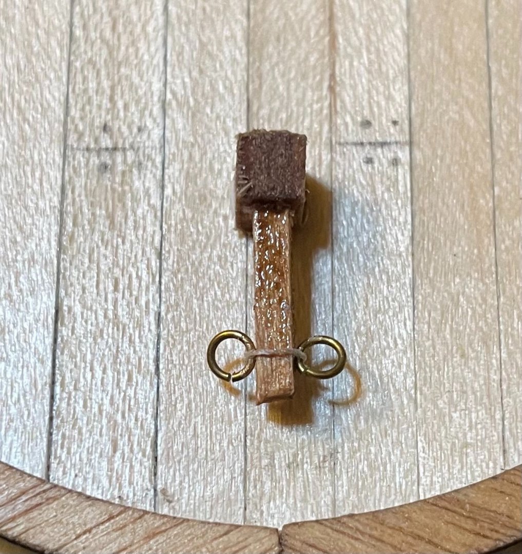
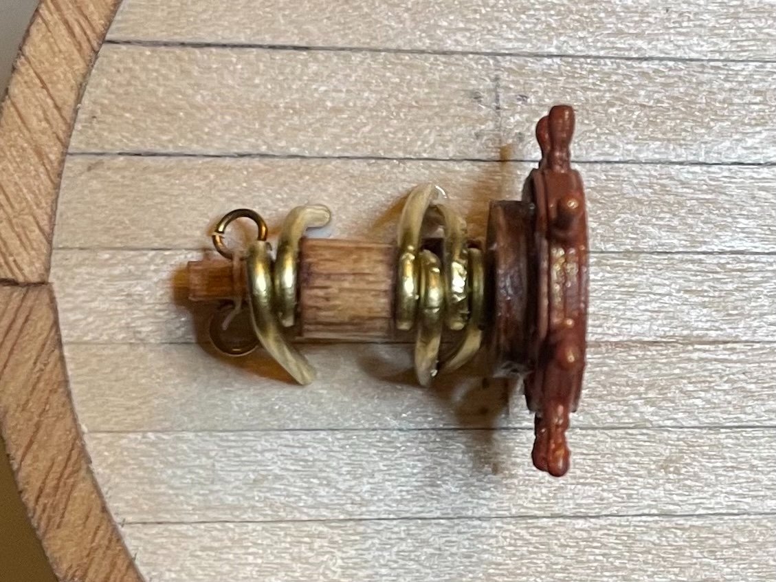
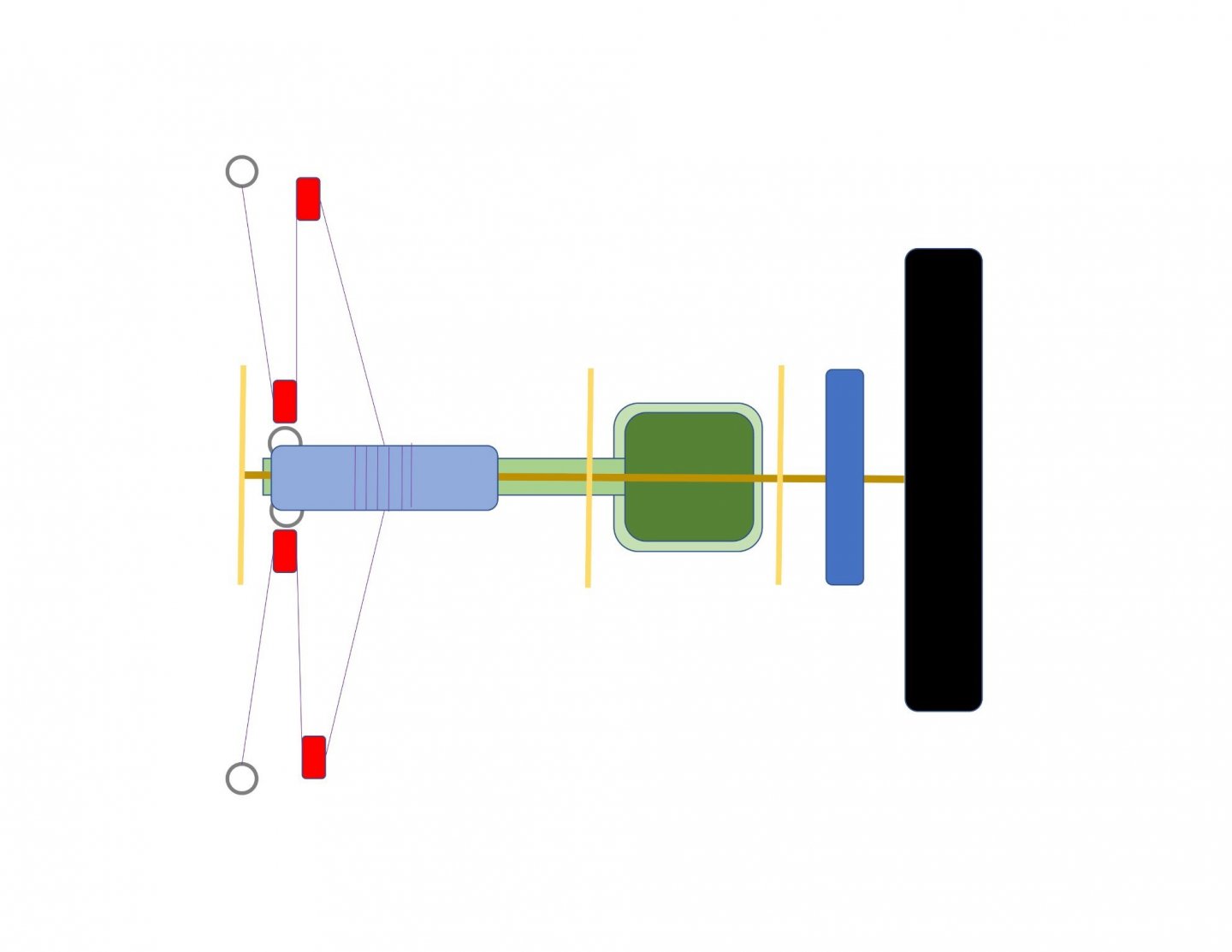
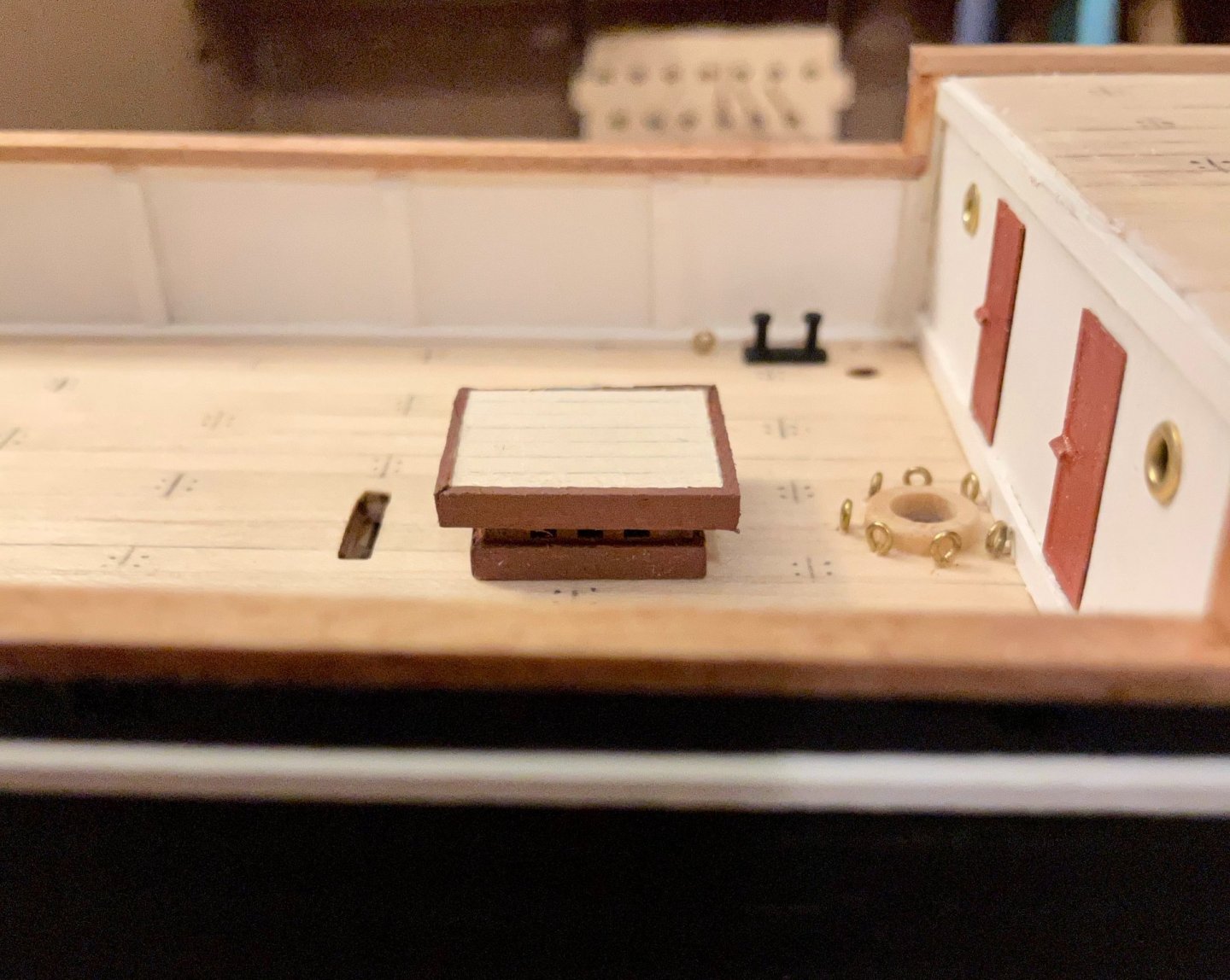
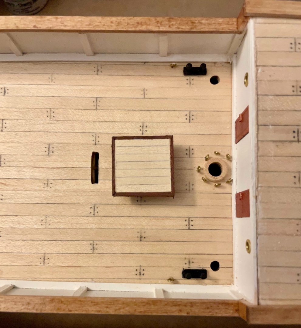
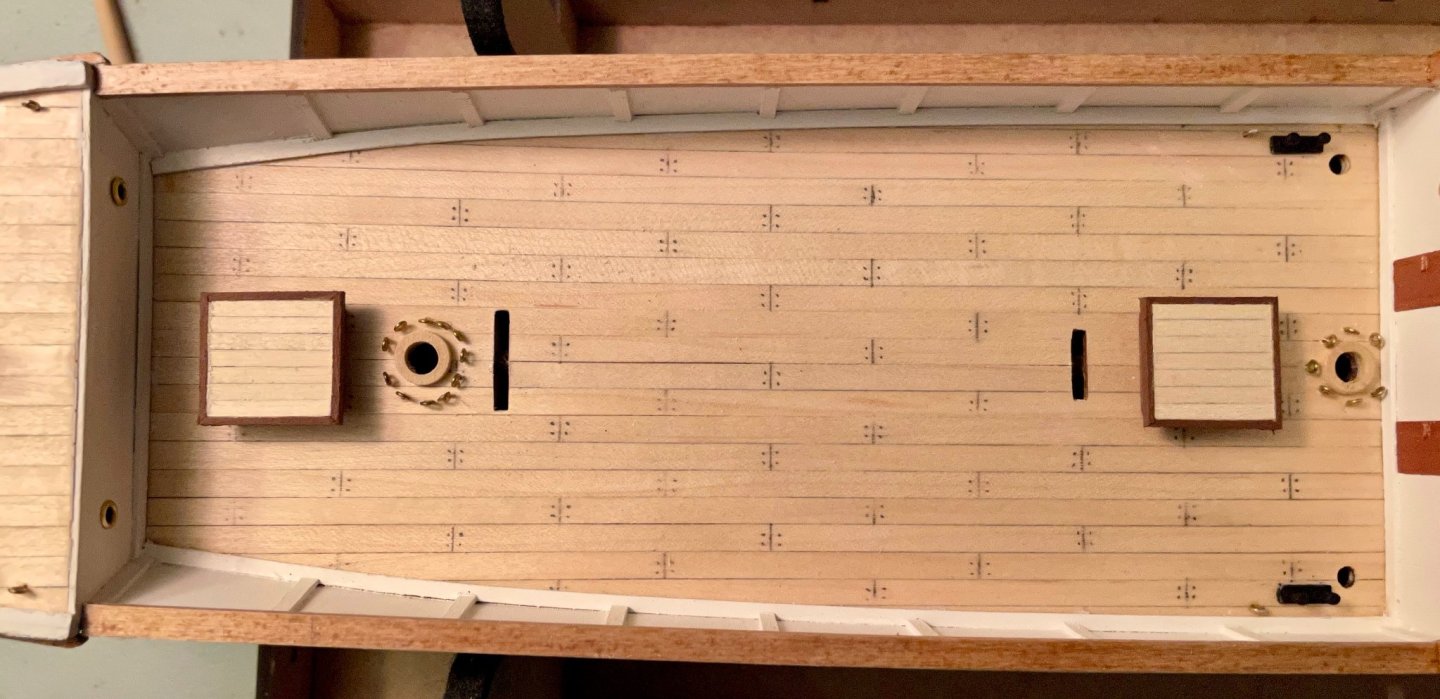
Today, I built and installed the final version of the steering gear! I started by assembling the top of the rudder out of a short 4x4 piece and the tiller out of a 2x2 piece. For stability, the joint is supported by a pin with the head cut off. I didn’t think could attach eyebolts securely, so I tied two rings onto the end of the tiller. This assembly is attached to the deck with a pin to support the joint. The tille is sagging a bit, but I think that will be better once it’s rigged up. The final version of the steering gear is similar to what I posted the other day. The brake is a little larger (it’s the bit cut out of the top ring on the smokestack) and the barrel has been trimmed down to fit better. A quick note: the kit has exactly as much 1.5mm brass wire as is called for, so there’s no extra to play with unless you supplement some. Even though the legs aren’t quite vertical, I’m pretty pleased with how this turned out. (On a related note, I touched up the paint job on the wheel after taking these photos.) Next steps: Painting the binnacles (which I had been forgetting about), then install all of the remaining deck fittings.

-
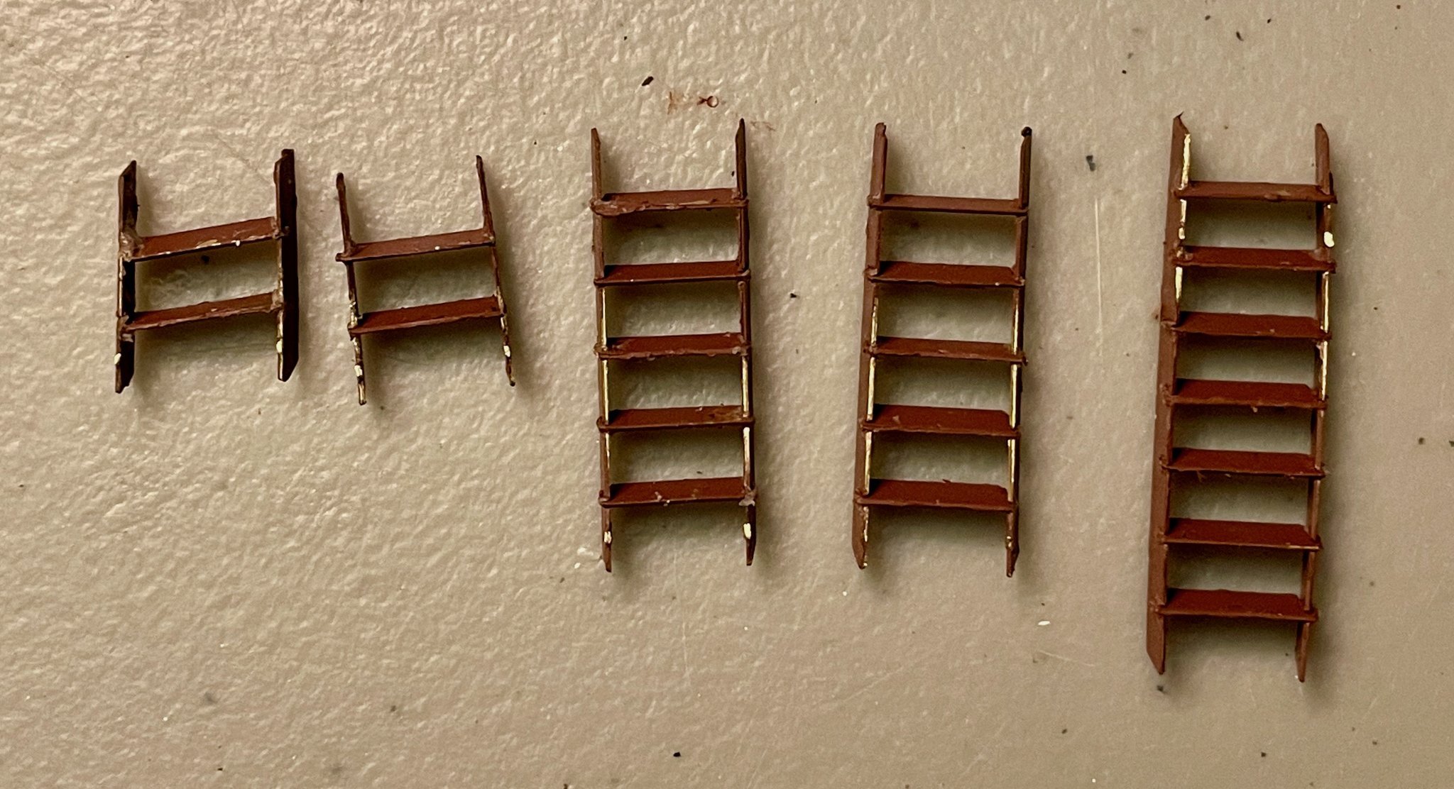
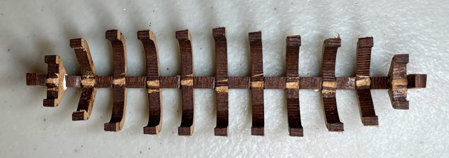
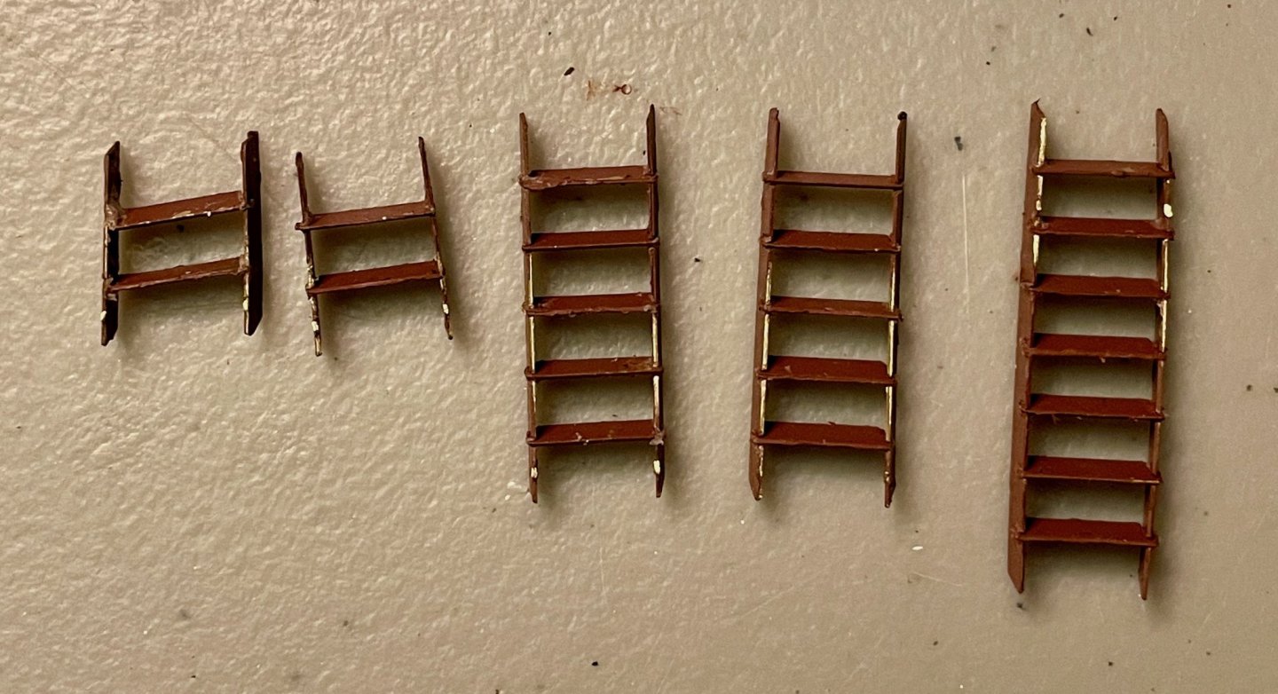
Thanks, Bob! Today may have been my most frustrating day working on the Endurance. It was bad enough, I had to just set everything down, walk away, and come back to it several hours later. The bit causing me such frustration? The stairways. Although I've made wooden stairways before, these are constructed out of thin, pre-cut brass plate. I pre-painted them, which may have made things a little tougher on me (and ended up irrelevant, since they will all need at least one more coat after being built). The challenge is that the tabs and slots are so small, it's very finicky work to assemble them. For the steps themselves, the burrs are on the ends of the tabs, so you have to file down the burr, but be careful not to go too far. By the time I finished up the first two—after assembling them, breaking them, re-assembling them, etc.—I started to get in a groove, at least until my back encouraged me to stop for the night. The one on the left in the photo was my first. When I took this photo, I noticed that the tabs on the steps of that one weren't seated well in the slots on the sides; I've since redone that stairway. Five down, three more large ones to go. I've also finished up the companionways. The companionway from the main cabins out to the aft deck is installed, since I had to do that to align the doors. Unfortunately, some overly enthusiastic sanding months ago means that it's not a tight seal around the doors...hopefully that's less noticeable in person than in these close-ups! The companionway to the bridge deck is just sitting on the aft deck here. With that one in particular, there's quite a bit going on. The basic structure is made from pre-cut plywood pieces that are lined with sapelli strips on all sides except for where the doors go. The roof pieces are built separately than installed; these consist of a center pre-cut piece and to pieces of 2x2 limewood that needs to be rounded. Both have 1x3 lower lining pieces on three sides. The doors are 4 strips with short pieces of brass wire as handles. The bridge deck companionway also has two squares of acetate in the windows and six bits of brass wire across the windows. It was very satisfying to see all of those pieces finally come together! Next steps: Finish the last three stairways, assemble the steering gear, and then install all of the deck fittings.
-
Since my computer died on Friday, I wasn’t able to get much done for work. But on the plus side, I was able to spend more time working on the Endurance as I waited for everything to transfer over to the new computer. So there’s been a flurry of activity on the deck fittings. There’s still a bit to do—finish constructing the hatchways and touch-up painting, for example—but it was pretty satisfying to sit back at the end of the evening and admire how things are coming along. Everything’s still just sitting in place, but I’ll be ready to attach them soon!
-
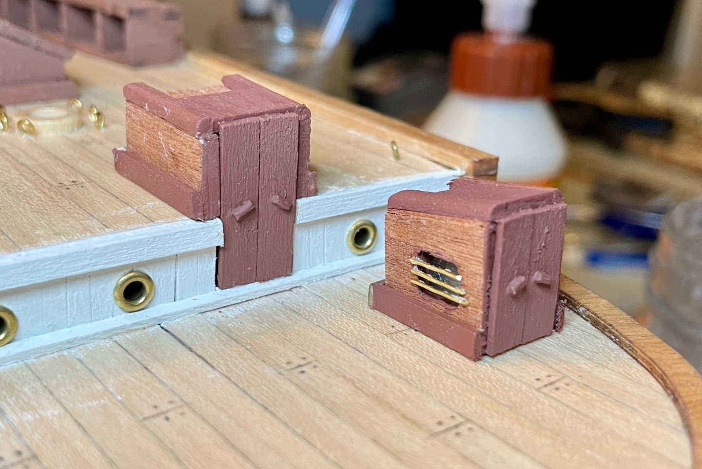
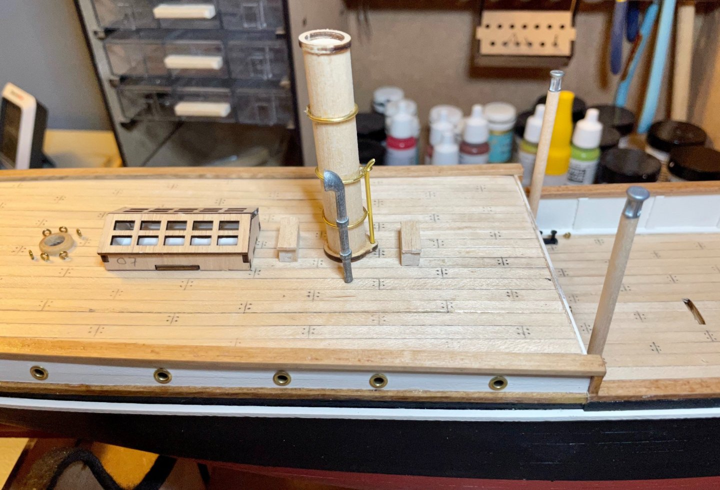
Thanks, Keith! I haven't had a chance to follow up yet, but I'll definitely head back over to the Lansing book to find what I had missed. I started work on the fittings for the quarterdeck this evening, just assembling the various bits and pieces. Most of this work is pretty straightforward and simple, so I made fairly quick progress in a 3-hour work session (though I notice a couple things in my photos that I will need to go back and fix tomorrow). The only thing not fully assembled yet is the skylight; I need to paint the top pieces first, then attach acetate pieces for the window, then I can finish assembling it. I also need to add the lining around the bottom. Everything's dry fit into holes or is just sitting on the deck for now. The key challenges for me were: Making brass rings around the smokestack and whatever those two poles are on the main deck. (Those poles seem to align with vents in the cargo hold for the coal...so maybe they're vents?) I followed OcCre's instructions and did an okay job, but this is a skill I need to continue developing. The lower wooden ring on the smokestack was a real pain. It needs to be filed down quite a bit to fit around the smokestack. Since it rests flat on the deck, it is the piece that defines the rake of the smokestack. While filing that ring, I managed to break it into three pieces. Thankfully, the breaks were clean enough that I could reassemble it on the smokestack and glue everything together. For those working on this kit, be gentle with that piece; it gets pretty fragile by the time you've filed it to fit on a 12mm dowel! Next steps: Touch up a few details on these pieces, then paint them.
-
Hi Keith, do you know anything more about the house over the steering gear? I don't see anything like that, even in the photos from the Weddell Sea, though I notice that by then they had put up some white material around the entire aft deck (as a windbreak? Canvas? Wood? I'm not really sure.) I'm not suggesting you're wrong about the house; I just haven't found anything on that yet and would appreciate any leads for more info. Thanks!
-
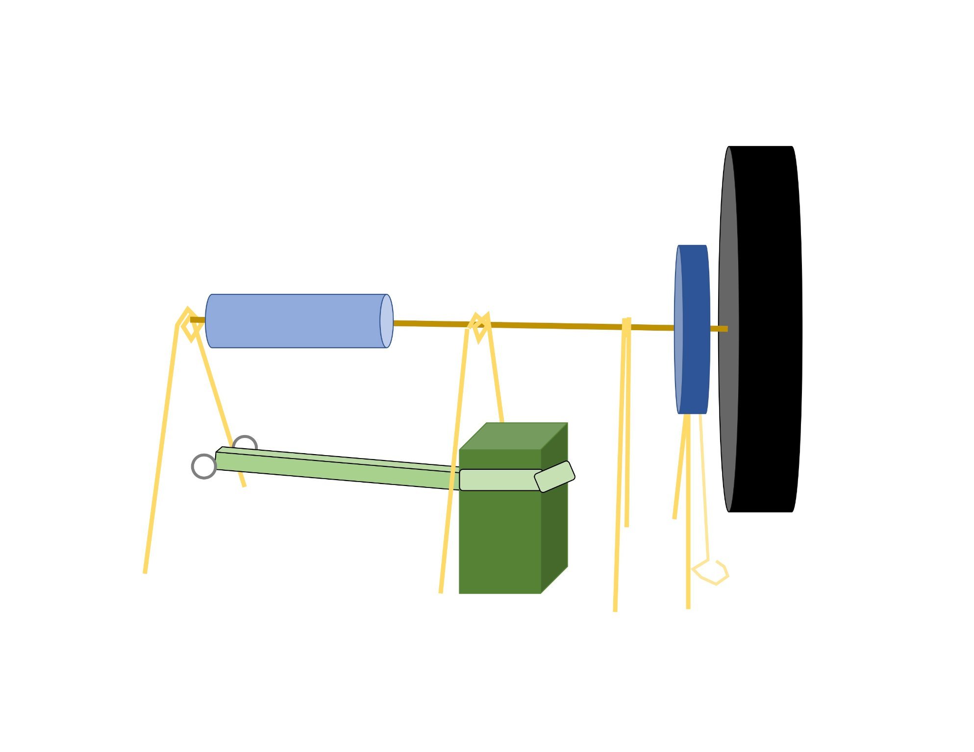
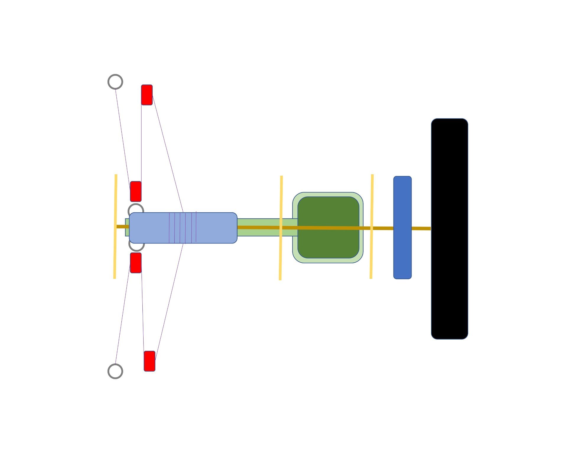
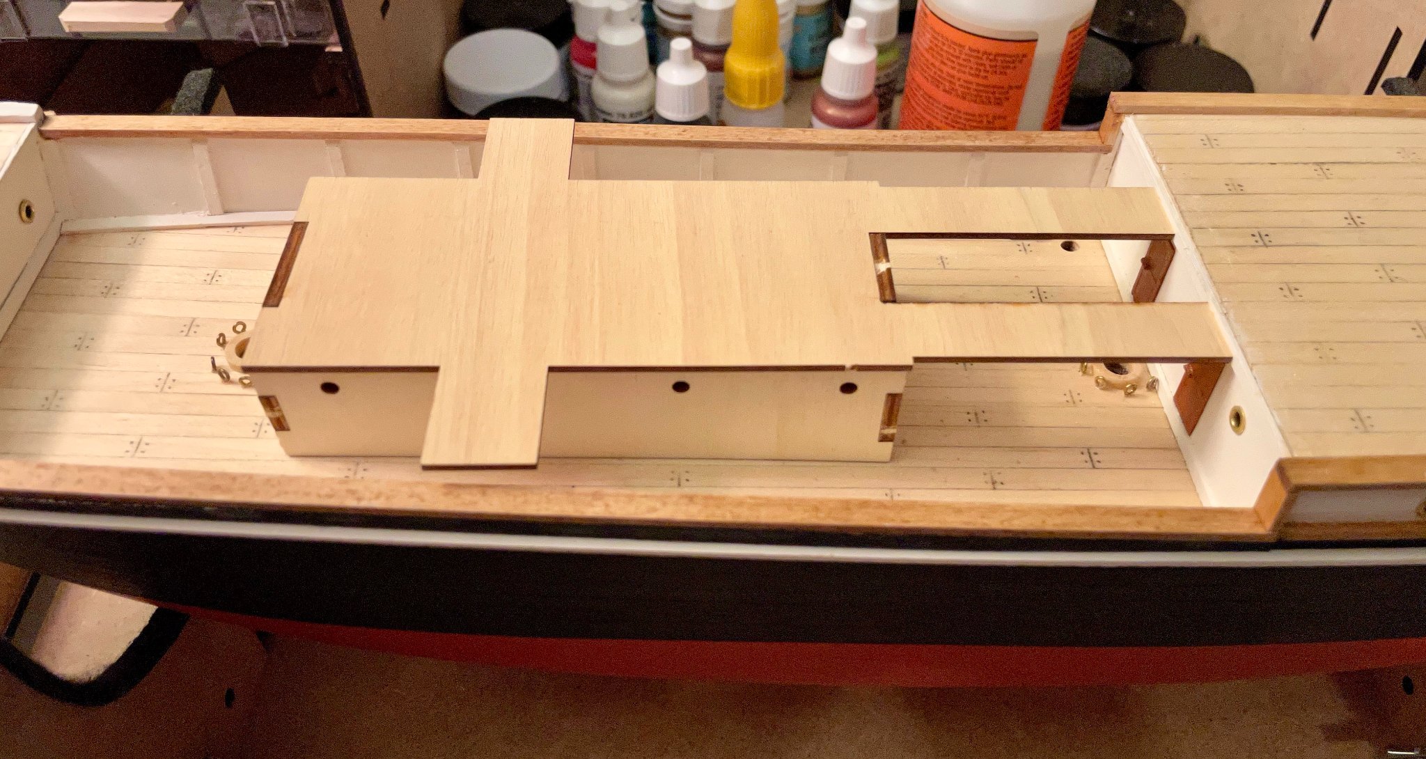
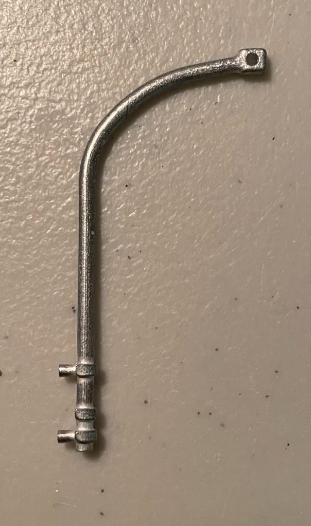
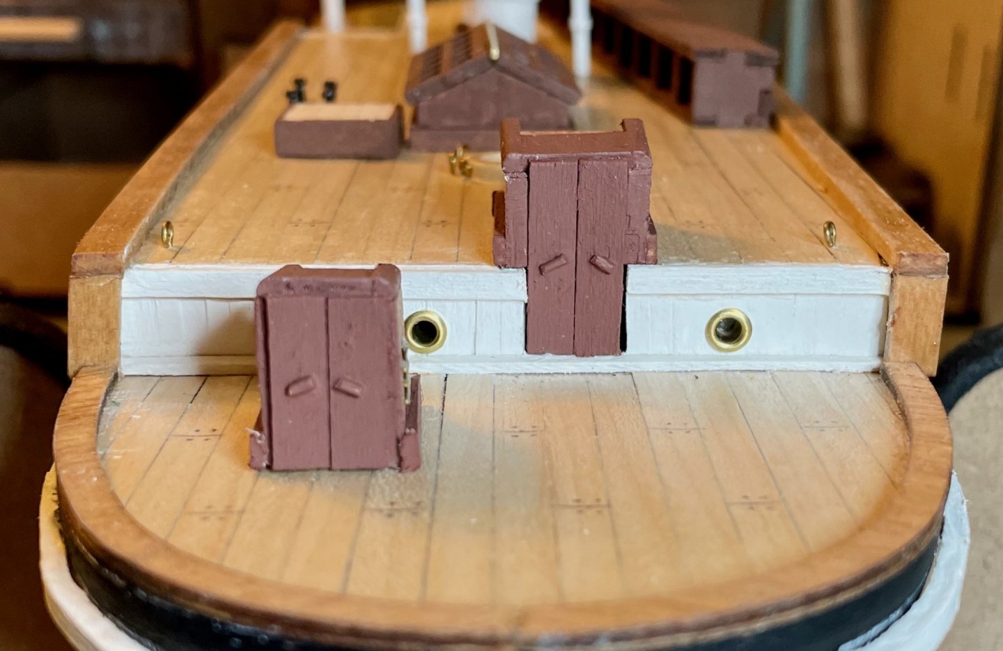
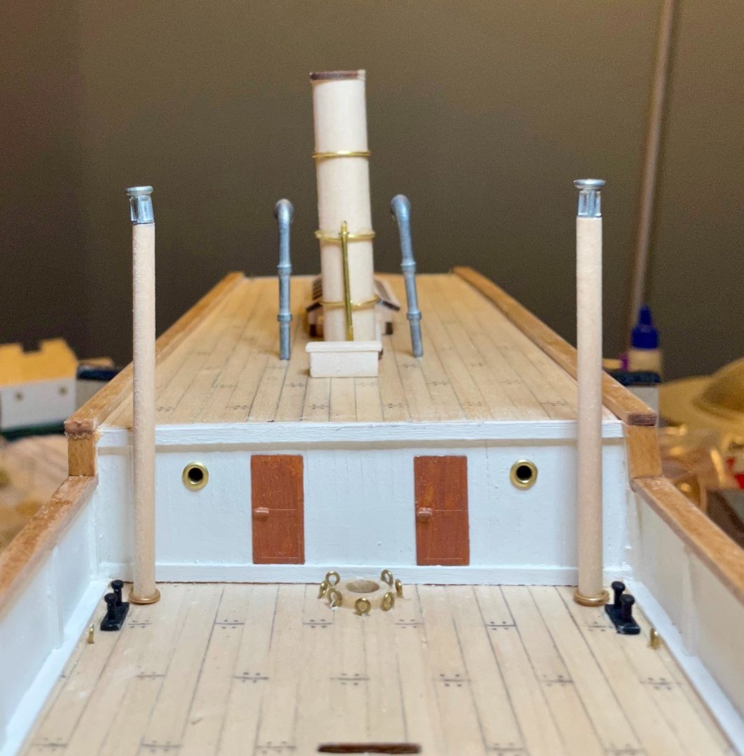
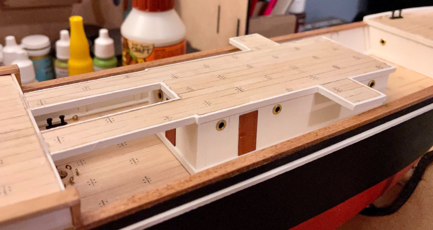
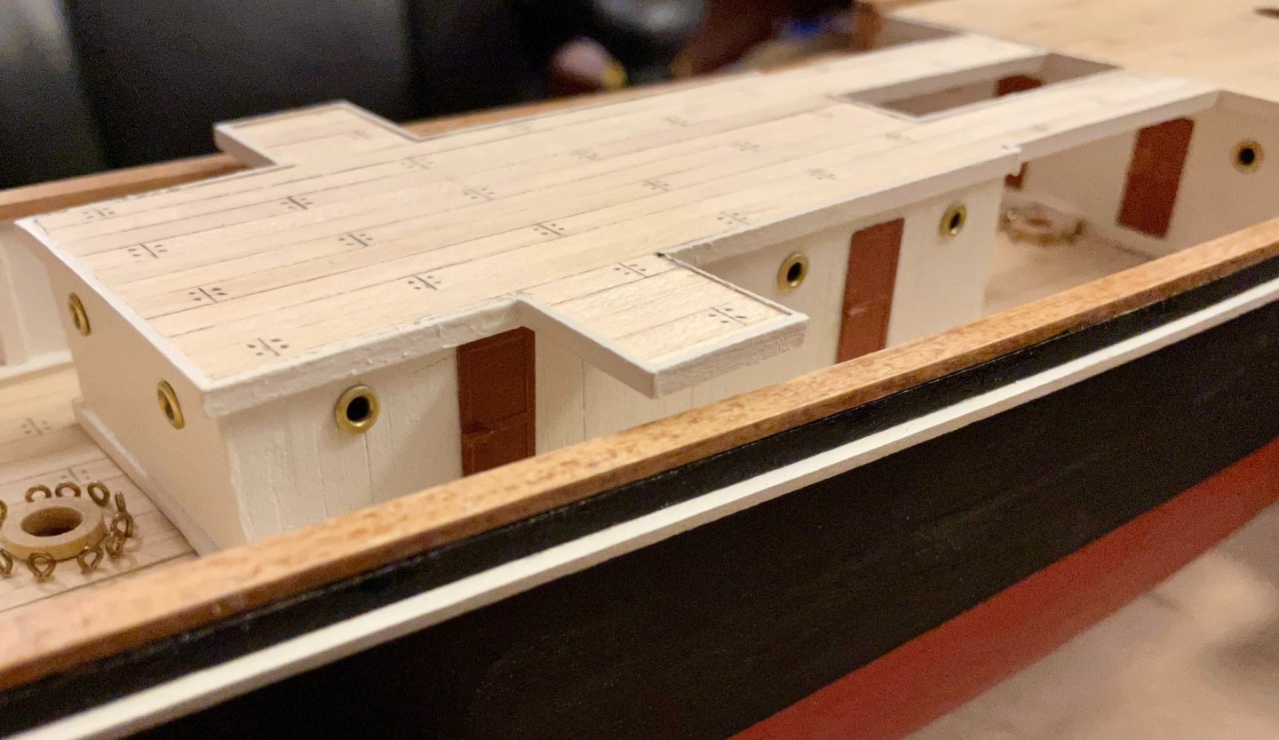
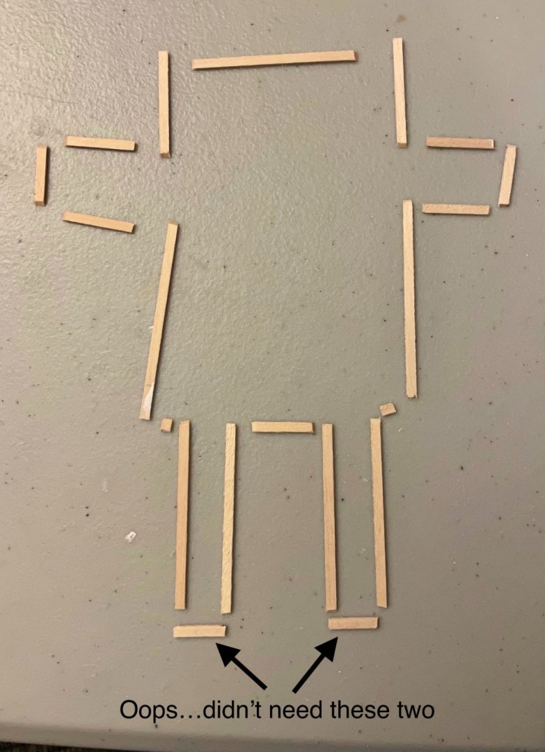
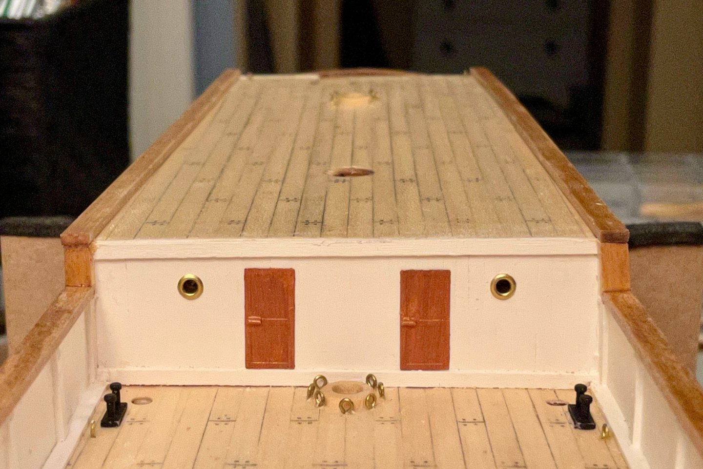
The Ritz is finished! I installed the portholes and doors this evening. A couple photos of it sitting in place (installation should happen soon, but there are a few other bits I'm getting together first). One quick note for those doing the kit and aiming for greater historical accuracy: the door placement in the plans is not accurate. The three doors around the dining saloon (the after part of the Ritz) should be centered between their respective portholes, while the door to the galley (forward port side of the Ritz) is a bit aft of its porthole. And, heading down a very different path... In terms of historical accuracy, the thing that bothers me most about this kit is what OcCre calls the "steersman cabin." I think that this is a design choice on their part to make the kit more accessible to beginner builders. But on the Endurance, there was no such cabin; the steering assembly was exposed. I've been studying the photos and pondering on this for a while. As somebody who thinks of himself as an advanced beginner, OcCre's solution is definitely doable. But perhaps I've developed enough skills to do something a little more intricate and challenging... At the very least, there's no harm in trying, since there's a safe back-up plan, right? With that in mind, I drew up some sketches over the past couple of weeks. The ones on paper are unreadable to anybody but me, but here's a digital version of the draft. This afternoon, I hit the hobby store for some brass rods, so I could experiment a bit. Here are two photos of the prototype I worked on this evening; no rudder/tiller yet. A few notes: The angle is a bit funky since one of the clamps is resting on the quarterdeck and is lifting everything up. All of the legs have been trimmed to the same length and they do actually hit the deck evenly. The barrel is too long here (about 8mm instead of the planned 5mm). It also looks too thick, though I'm not sure I can drill through anything thinner without destroying the dowel. There's a big chip out of the brake. Not sure when that happened, but I'll have to do a new one of those for sure. The legs for the brake aren't shown here since they kept falling out; should be fine once there's glue involved. For the brake legs, I ended up using brass pins with their heads cut off. I don't think I'll be able to make the brake pedal work well. A matter of skill and materials, so others might do better on that. Overall, though, I think this will work and will be more satisfying to look at. I'd appreciate any feedback that you all might have, before I make a second version.


-
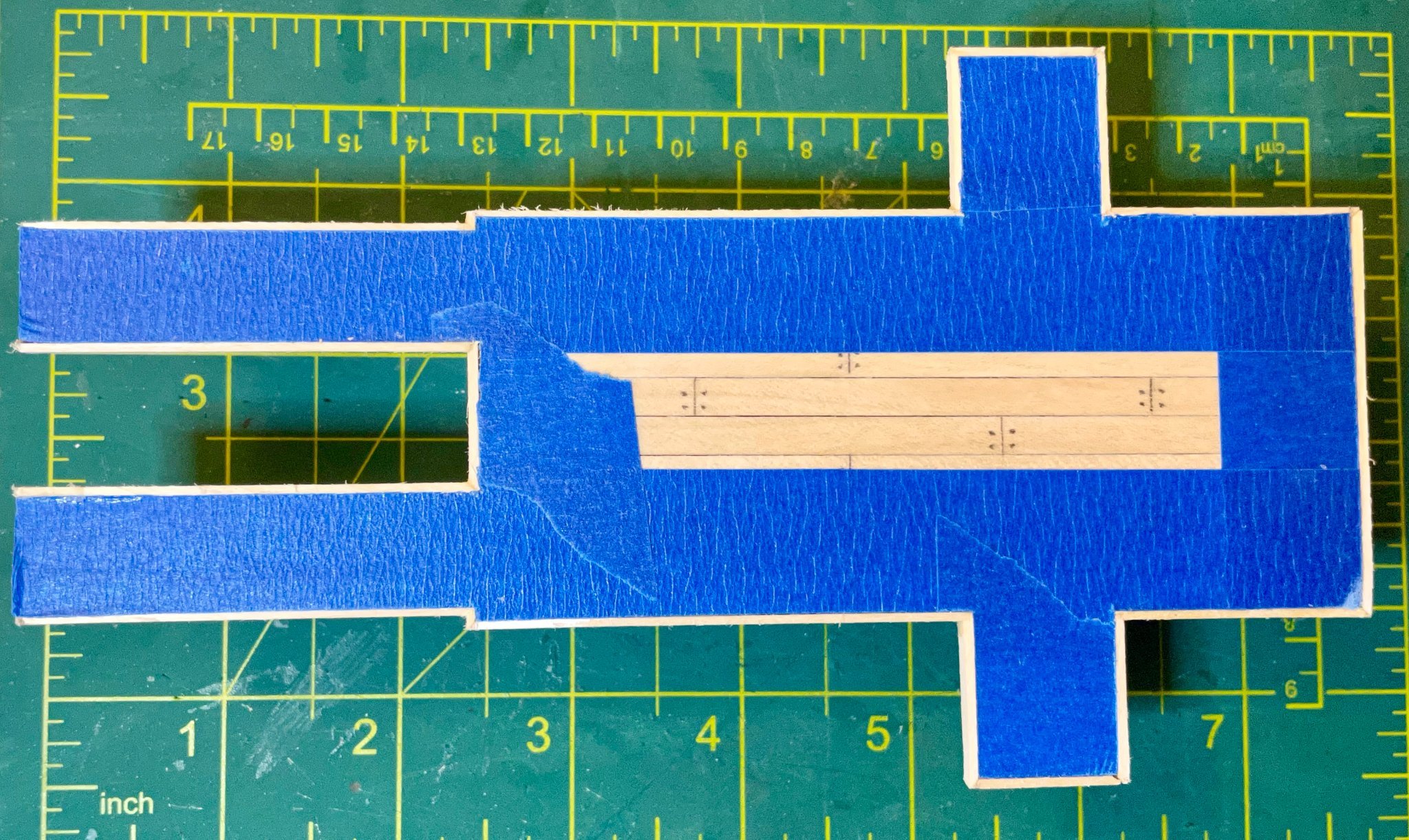
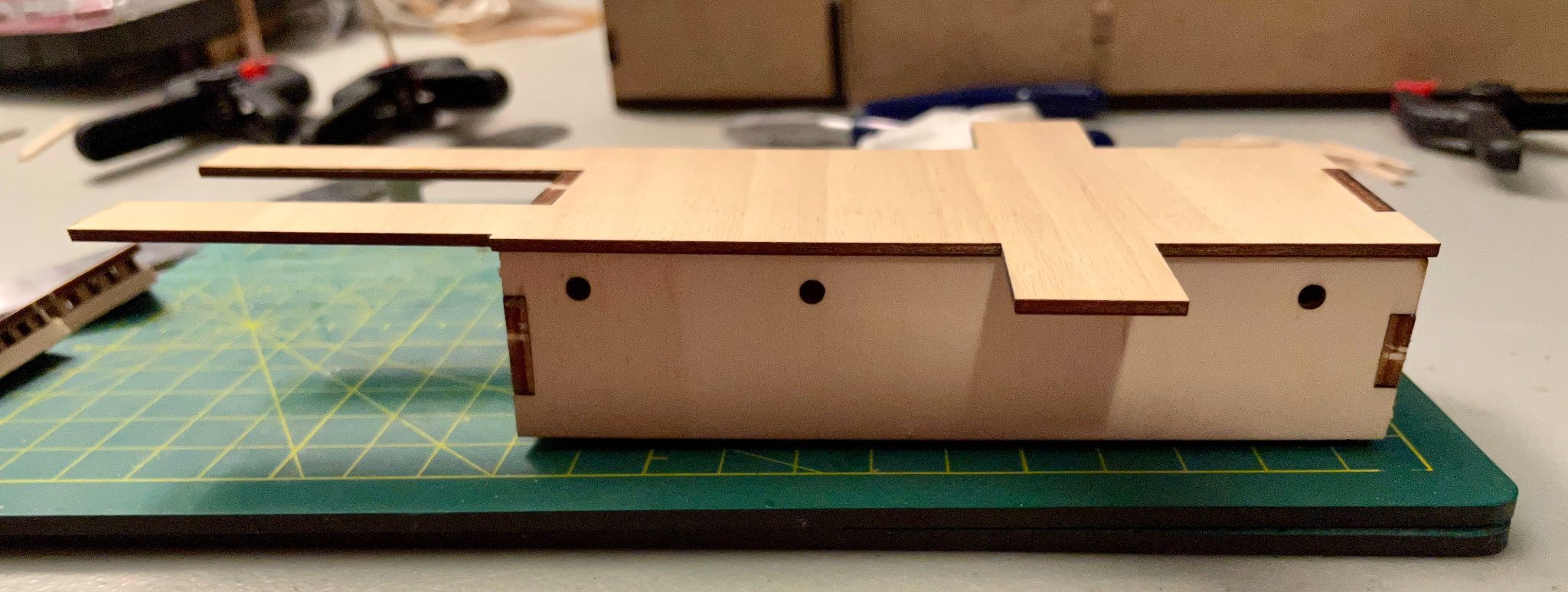
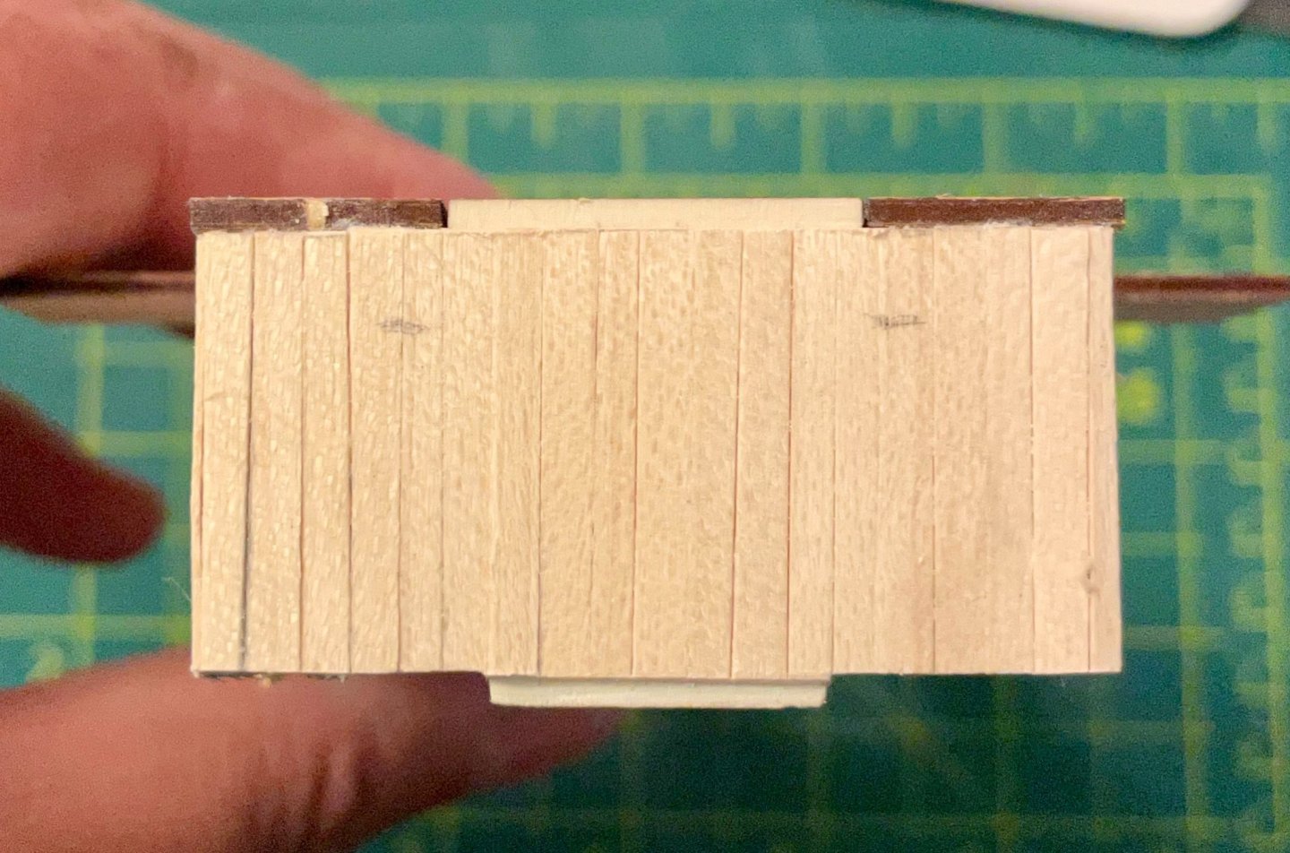
We have some unexpected guests coming tomorrow, which means I need to tidy up the shipyard as much as possible. So, I pushed a bit the last couple of days to finish building the Ritz. I'm pleased to say that I just finished the bridge deck and am really pleased with how it looks! There's still a bit to do on the Ritz, but the hard work is done! After finishing lining the sides, I planked the bridge deck. Once the glue dried, I trimmed and sanded the edges, then drilled out and filed the portholes. Next, I added the lines and dots to simulate planks and treenails. I also did a dry fit to ensure that the ends of the companionways still fit correctly against the main cabins. (Note, the skylights are still just sitting on the deck. I'll install them once the Ritz is ready to be attached. Then the tedious work really began. I've added the lining around the bridge deck, using the same mitre joints I used on the linings of the skylights. Thank goodness for my mitre shears, which are my secret weapon for this kind of task. The lining consists of 18 separate 1x3 limewood pieces (though I made two extras because I forgot that there's no lining where the companionways meet the quarterdeck. The two smallest pieces were too small (3mm long) to put in the two mitre joints, so they each have a mitre joint on one end and a simple but joint on the other. Before attaching these lining pieces, I lined the bridge deck with painters tape and used my Exacto knife to trim the tape right at the edges. The finished lining turned out as close to perfectly as I got have hoped for. Next steps: Add the lower lining (not called for in the plans, but will match what I did for the forecastle and the main cabins), then paint the Ritz. After that, I should be ready to install the remaining fittings for the main deck.


-
Hi Bob, Glad to see you getting back to your beautiful ship, though a year spent with your guitars and bike sounds like a year well spent to me. All best, Hake
-
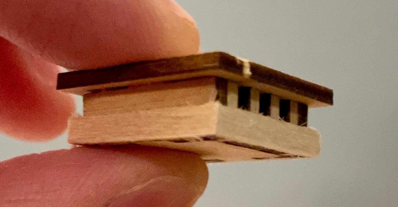
Thanks for the tip on the catheads, Keith. I'll take that sound advice and hold off as long as I can on those. A short update on my work from the last couple of days: First, I've finished the skylights. After the last post, I planked the top with 1x3 strips that I "caulked" in the same fashion as the deck planks. After I sanded the edges smooth, I put some painter's tape on, then installed the upper lining (with the same mitre joints as the lower lining). The last coat of stain is still drying, but I pulled the tape off and was so pleased with how they turned out that I couldn't wait to snap a couple photos with them sitting in approximately their final positions. First, two detail shots from the side and from above, then a view of both on the main deck. In addition, I've started the process of planking the sides of the Ritz. Although the plans don't call for this, I like the texture that this detail adds and I'm doing it to match the lining that I added to the forward and aft bulwarks on the main and aft decks. It's slow going, but OcCre has been very generous with the woodstock and there's plenty to be used for this. At this point, I've more-or-less finished the forward and aft bulwarks and have started on the starboard side. The pencil marks in the photo mark the locations where I will need to drill out the bulkheads. Next steps: Continue lining the sides of the Ritz, then plank the bridge deck (the top of the Ritz).
-
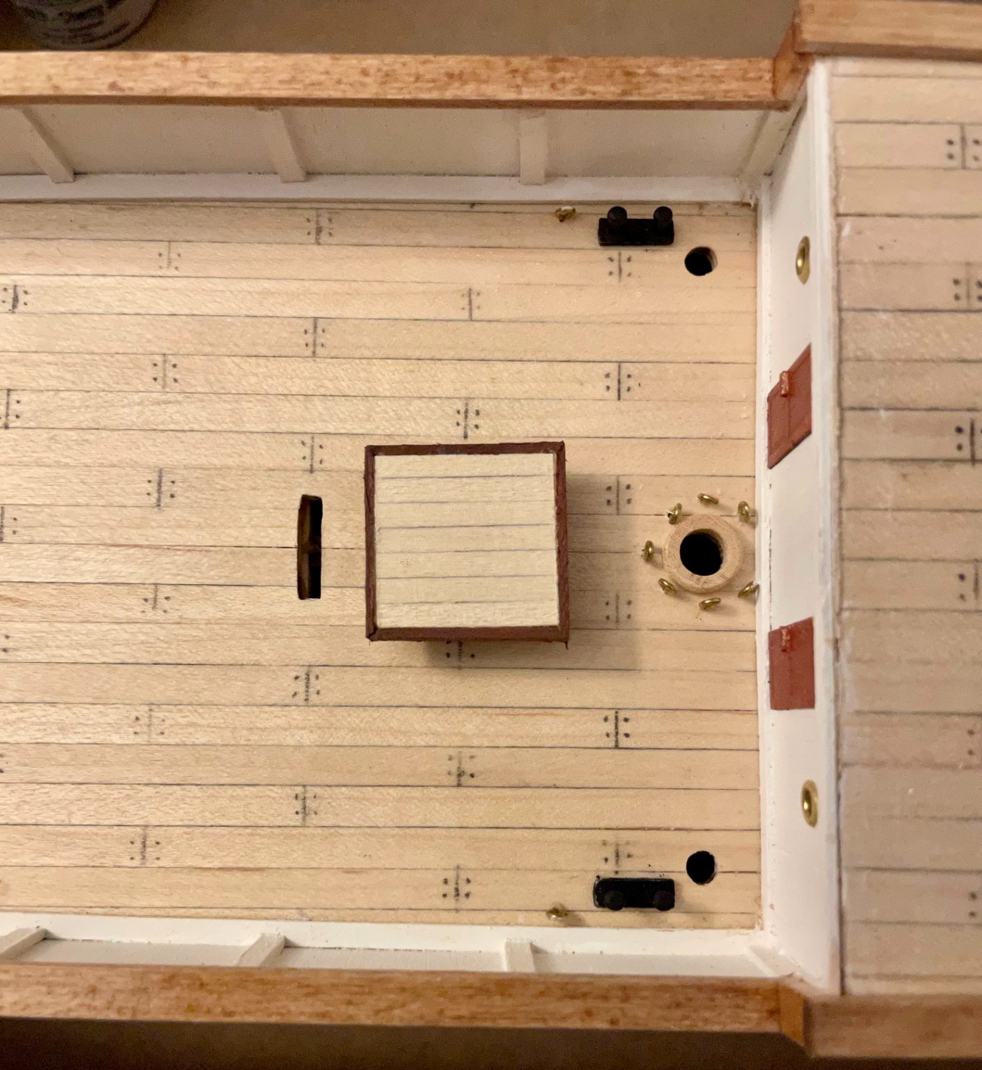
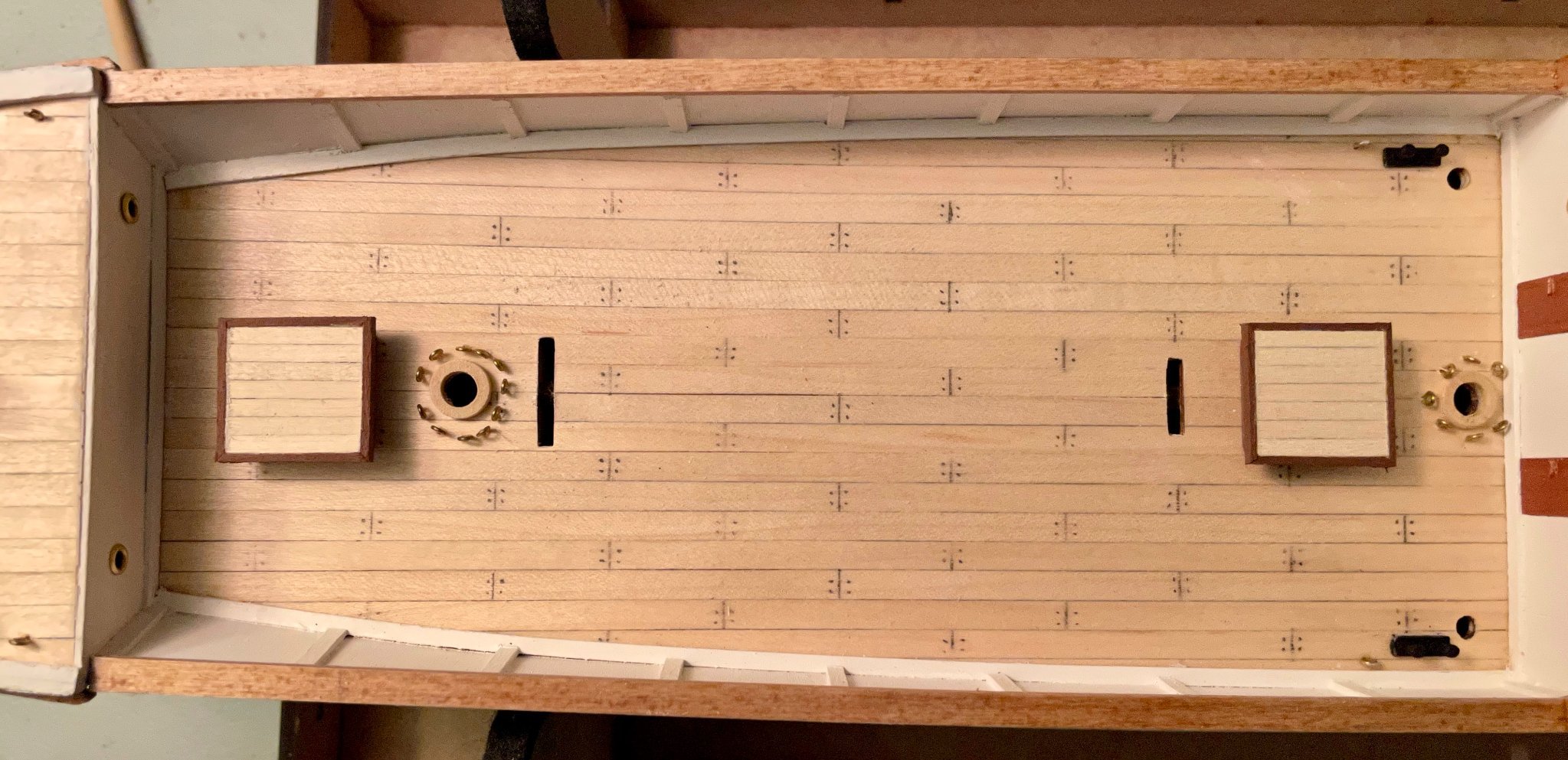
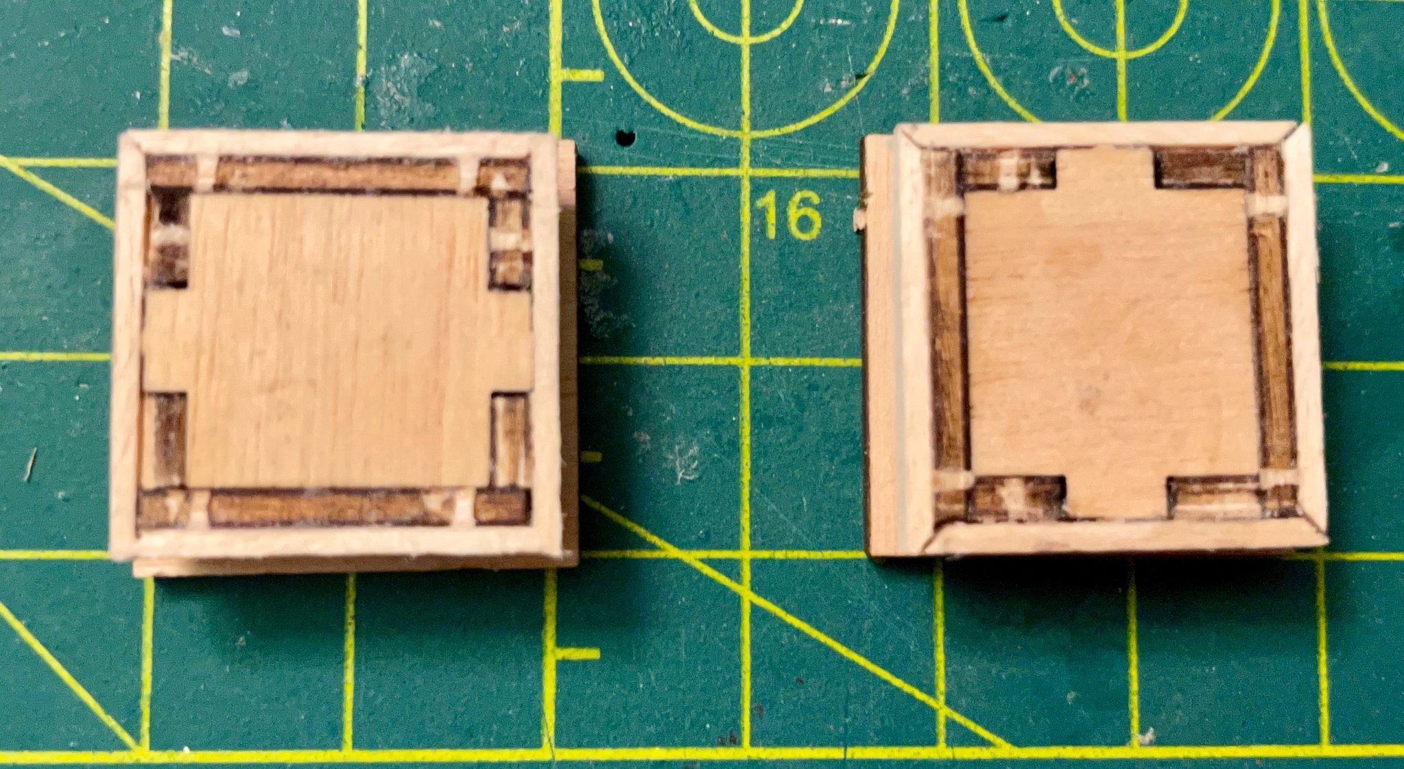
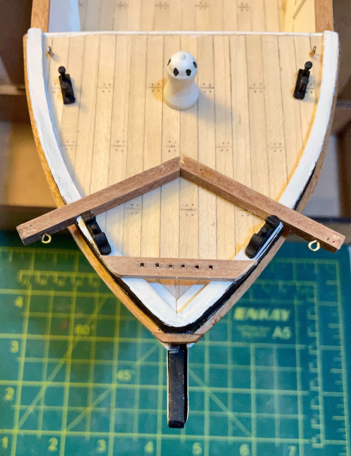
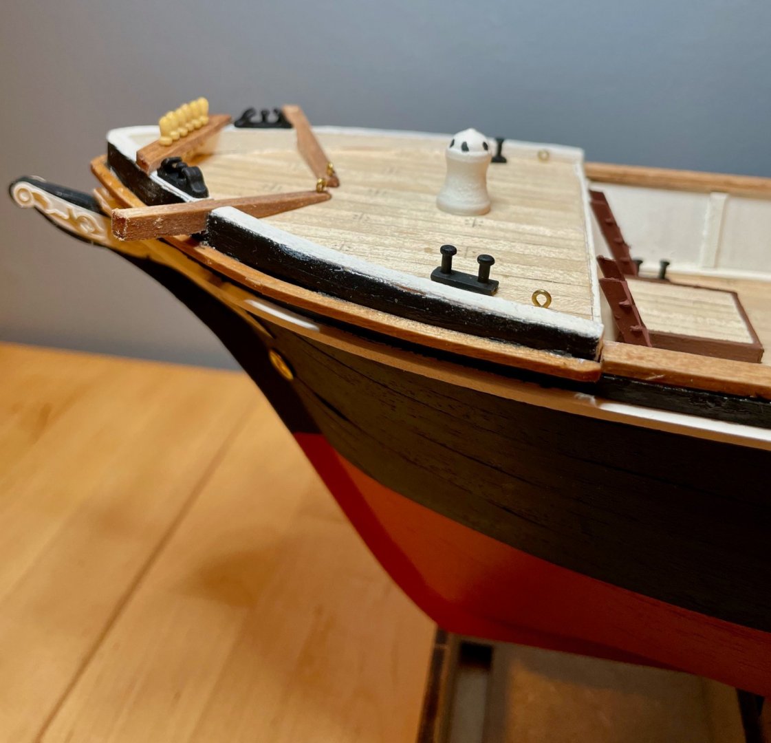
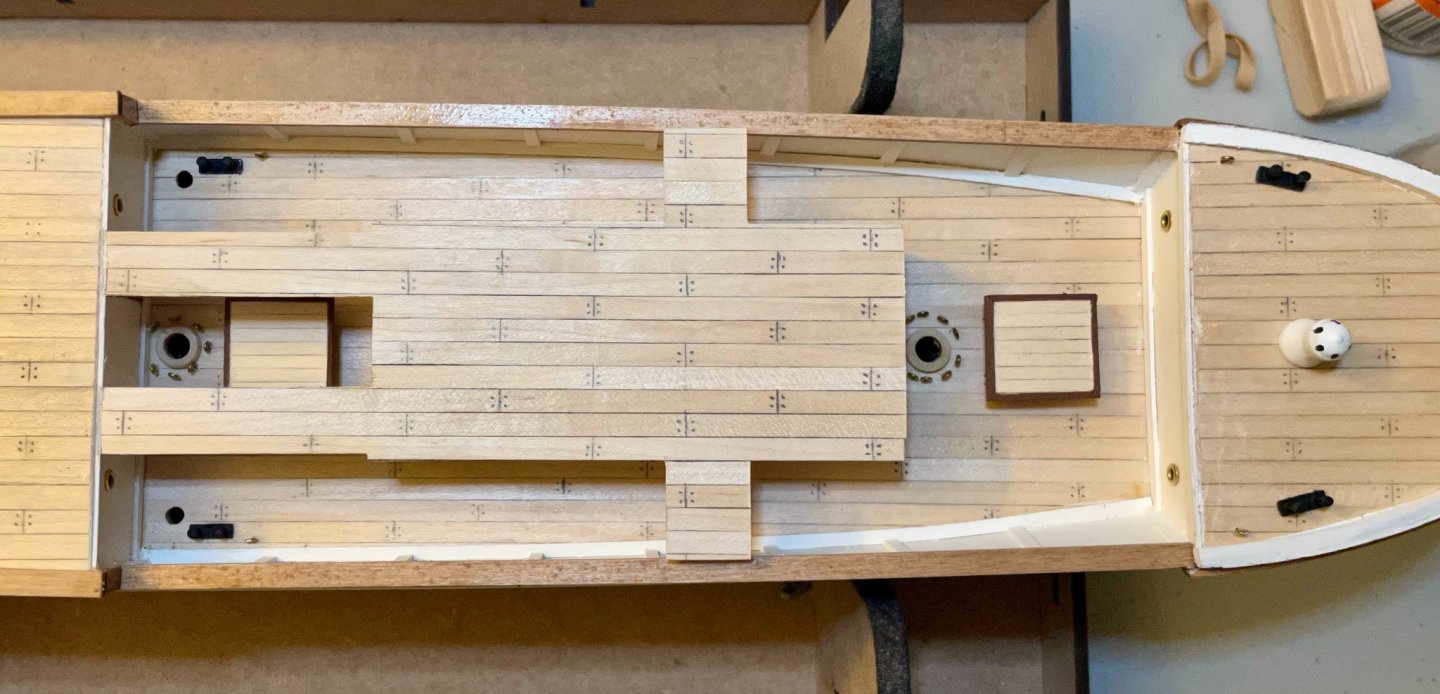
It's always nice working on the small bits—progress seems so quick, especially when most of them are pre-formed! I put in some work this morning and this evening and have made some satisfying progress. But first a quick note for those building the kit: I'm finding it extremely helpful to be working on steps M, N, O, P, and Q simultaneously. I'm moving back and forth between those steps primarily because it's helping with alignment, positioning, and similar things. In addition, most of the pin racks are made and installed in step M, but the pins aren't installed until step Q; I feel pretty nervous about installing the pins so much later, so am planning to have them in when I install the racks. And that's a good thing, too—when I tested the fit of a pin, I discovered that the measurement for the drill hole in the instructions is off—1.5mm was not sufficient for the pins, but they fit snugly at 1.6mm. Anyhow, some photos of what I've been up to the last couple days. First up, the foredeck. I dabbed on a bit of black paint to simulate holes in the capstan. It's still over-sized, but at least looks a little more functional now! As near as I can tell, the Endurance's capstan had six holes, so I did the same. I shaped the bow pin rack and tested pins in all of the holes. I also shaped the catheads and installed one eyebolt on each. There will be a second eyebolt, but I need to make a decision first. In the kit, the 4x4 planks just lay flat on the foredeck, but on the Endurance (and every other cathead I've seen!) they angled upwards (or tapered down to the deck, depending on how you think about it). I have a feeling that I will be tapering them, but I haven't made a confident decision yet. In the meantime, here's a photo of the fittings on the foredeck; the capstan and bollards are attached, but the rest is just dry-fit for now. Next, the after part of the main deck. In step M, the instructions call for installing the doors and bollards here. However, the doors are supposed to line up with the gangways between the bridge deck and the quarterdeck. So, jumping ahead to step M, I began assembling the "Ritz." Although the four walls and the ceiling/subdeck went together beautifully, I needed a bit of work to get them on deck. The tabs on the bottom of the Ritz fit into two slots in the main deck. Back when I planked the deck, I filed those slots down to fit the tabs...but once the Ritz was assembled, the alignment was a bit off. In addition, the gangways are 1mm too long—either I needed to sand them down or I needed to cut out a bit of the trim piece at the top of the main cabin's forward bulkhead. I opted for the former, along with filing down the tabs on the bottom of the Ritz. Once everything fit, I used angled tweezers and a bit of CA glue to position the doors. Finally, I've begun assembling the two main deck skylights. The six precut pieces for each fit perfectly. After the glue dried, I added the lower lining. These four strips are cut from 1x3 limewood. The instructions call for a basic butt joint, but in my previous kits I learned to do mitre butts and half laps. Given the position, I opted for mitre butts. One turned out as close to perfect as I could have hoped for, while the other needed a little sanding to cover up some very slight misalignments. I'm currently staining the side pieces and lining with a cherry stain (the plans call for sapelli, but cherry was the closest I could find when I was shopping). Next, I'll plank the top piece, then line the sides of it with more 1x3 strips. Next steps: Once I make a final decision on the catheads, I will finish installing the foredeck fittings. On the main deck, the focus is on finishing the skylights and the Ritz.


-
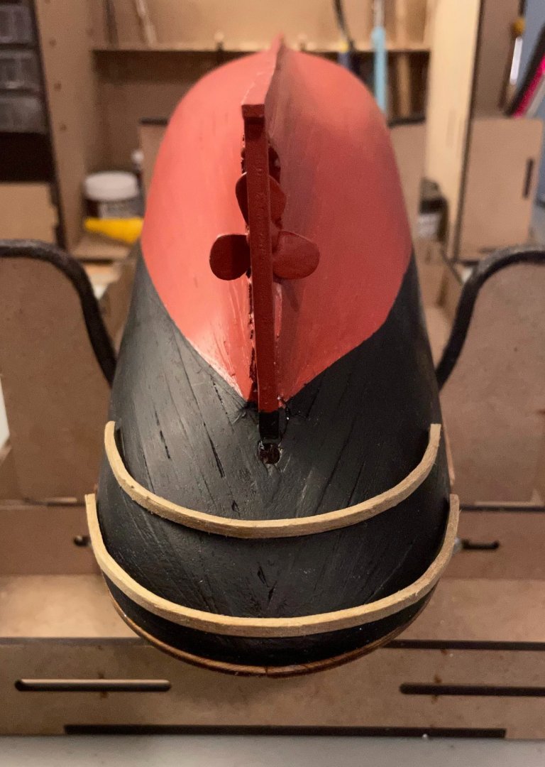
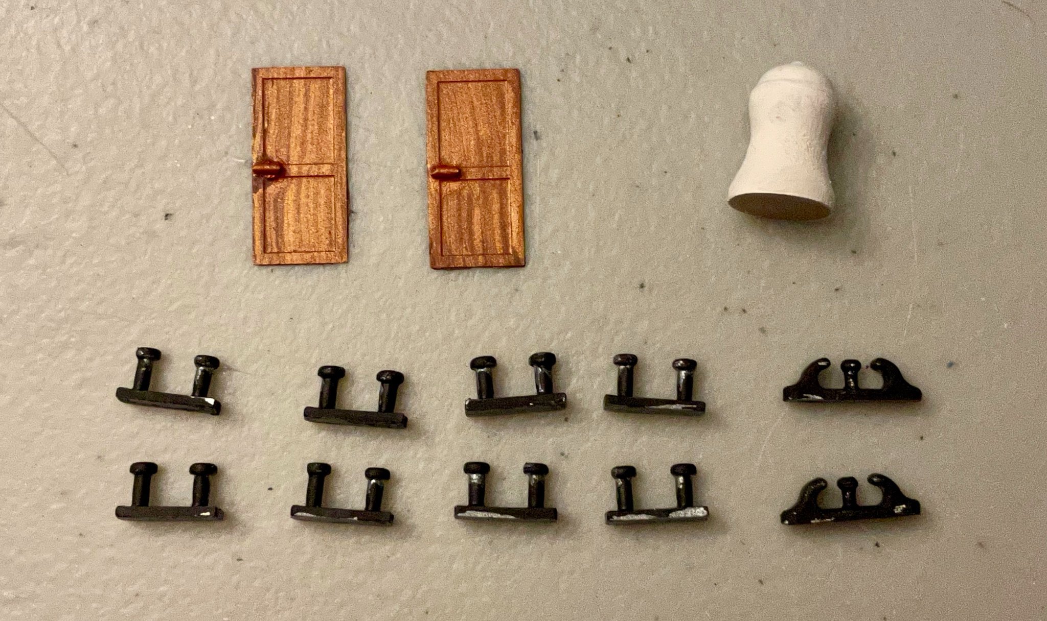
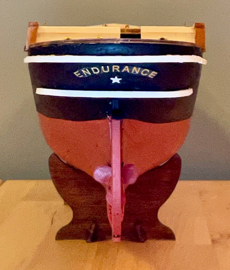
Thanks for the likes and comments, everybody! I couldn't agree more, Keith! All of my finished ships are lined up in my office and it's a refreshing reminder of how far my skills have progressed over the past 16 months or so. I tend toward modesty in discussing my skills, but as Tom notes, I do feel quite proud of my accomplishments thus far. Eurus, you made me go back and do more research. I've only been sailing once and that was 25 years ago, so I definitely have a lot to learn! Based on what I've read, shipbuilders/owners *can* paint the screw with the same antifouling paint as the hull, but people rarely do for reasons of cost and possible effects on the screw's efficiency. There's one photo of the Endurance in drydock, with the original paint job, that perhaps suggests that the same antifouling paint was used on the screw (definitely room for interpretation there for folks more knowledgeable than me). I'll use that as my justification, but when pressed, will just shrug my shoulders and say, "I don't actually know what's correct." After taking a couple days off the Endurance, I've started preparing the various pieces for the M steps. This involves quite hardware for the main and foredecks. This photo shows the doors, capstan, 8 pairs of bollards, and two cable channels. (I think I have the right terms for all of that!) The first coat of paint has gone on, so these are still a bit raggedy looking, but I already like the wood effect on the doors! This is per the recommendations of OcCre. The doors themselves are precut brass pieces, with short pieces of brass wire attached as the door handles. The paint is a layer of mahogany brown, then a layer of copper lightly brushed over the top while the brown was still wet. Apart from these 13 pieces, I've drilled the holes and put the first coat of stain on the catheads and the various pin racks on the main and fore decks. A note for those building the kit, the capstan is massively out of scale. If you're interested in a more historically accurate look and have a lathe, you may want to invest some time designing your own. (I think Snug Harbor Johnny also recommended this early in my build log.) This is the clearest photo I can find of the capstan. Some of the photos of the wreckage can give you a better sense of the shape of it (for example, zoom in on this photo and you'll see it pretty clearly just below the Getty Images logo).

-
Beautiful work, Keith! I'm particularly admiring how your counterstern is turning out.
-
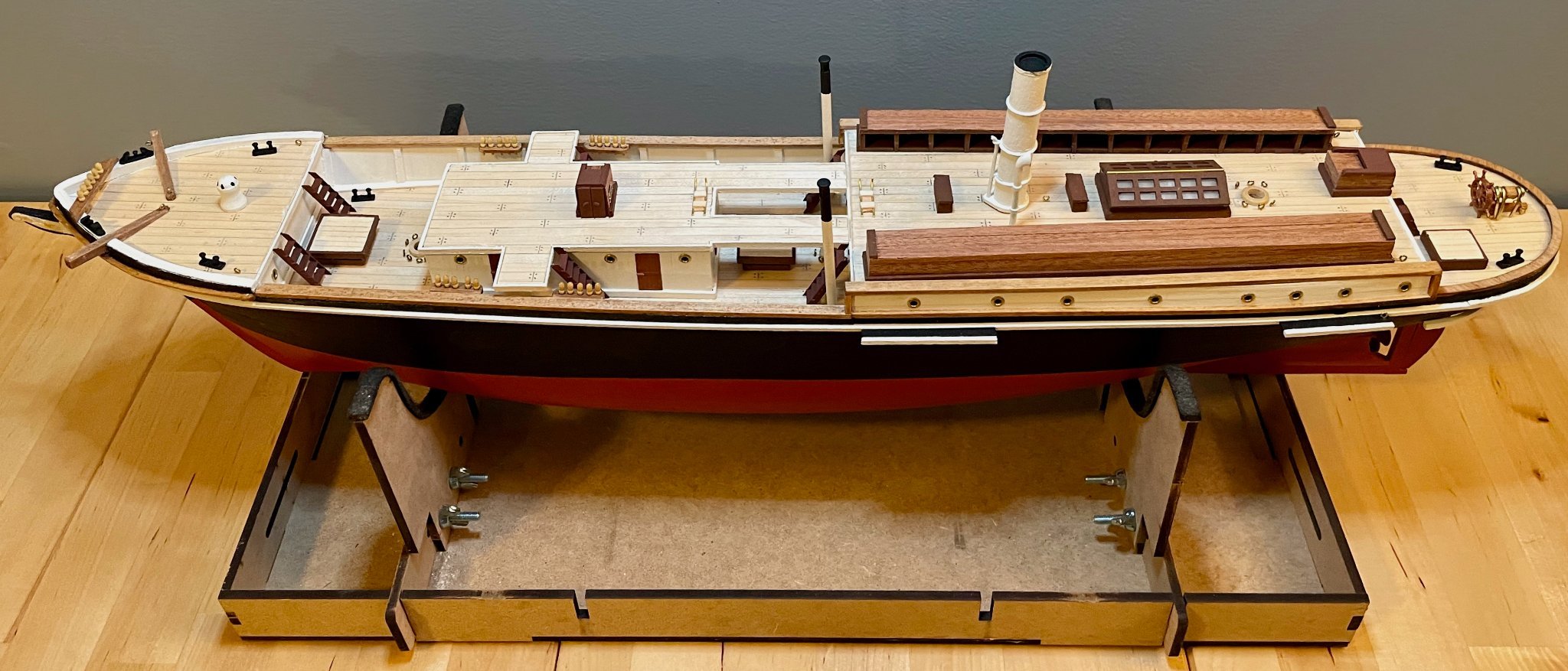
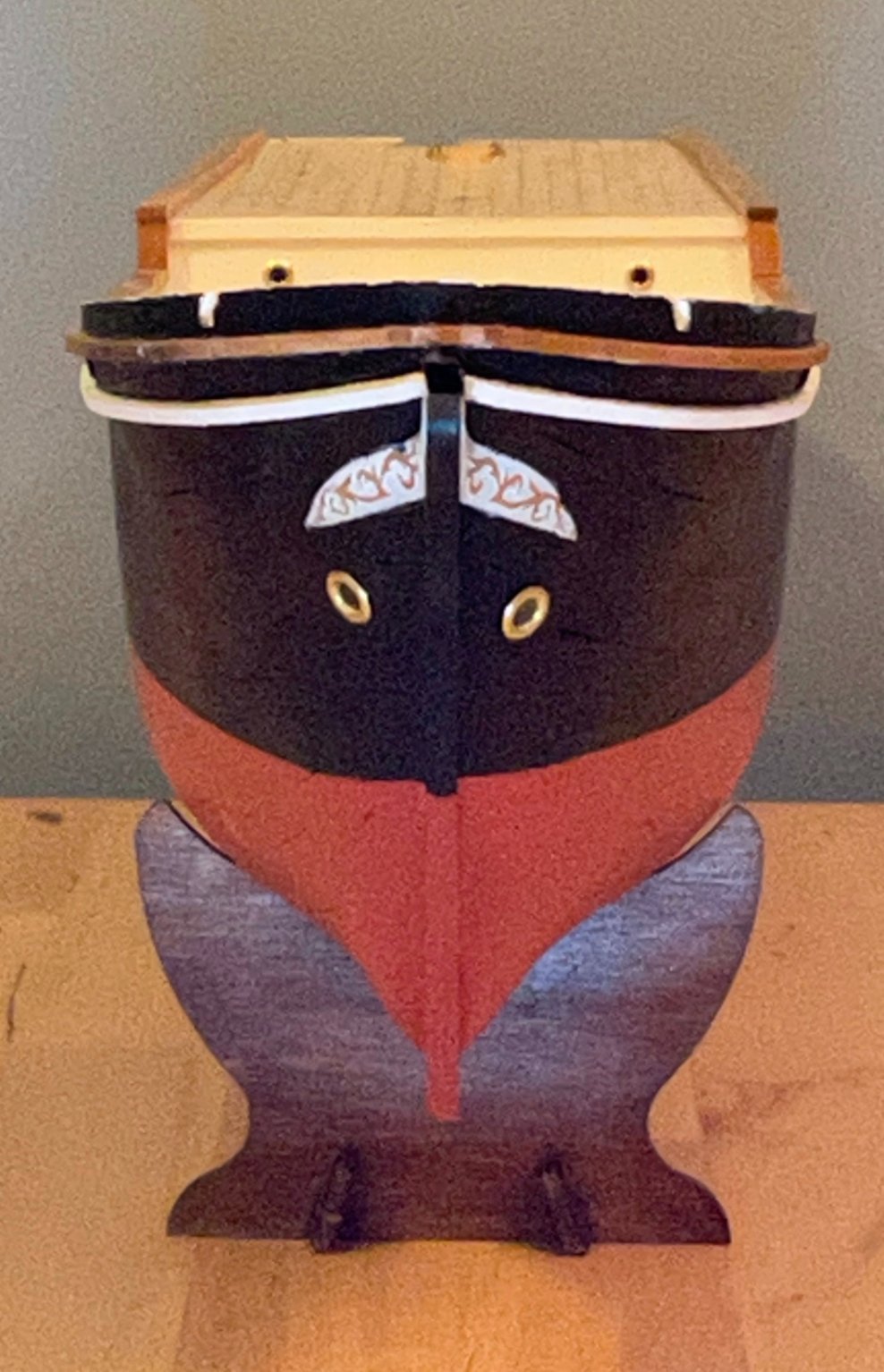
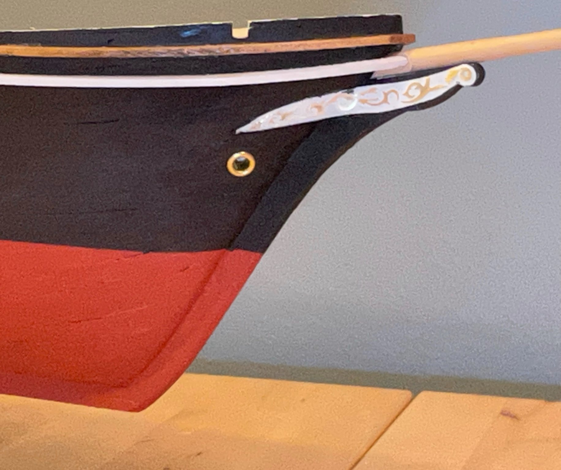
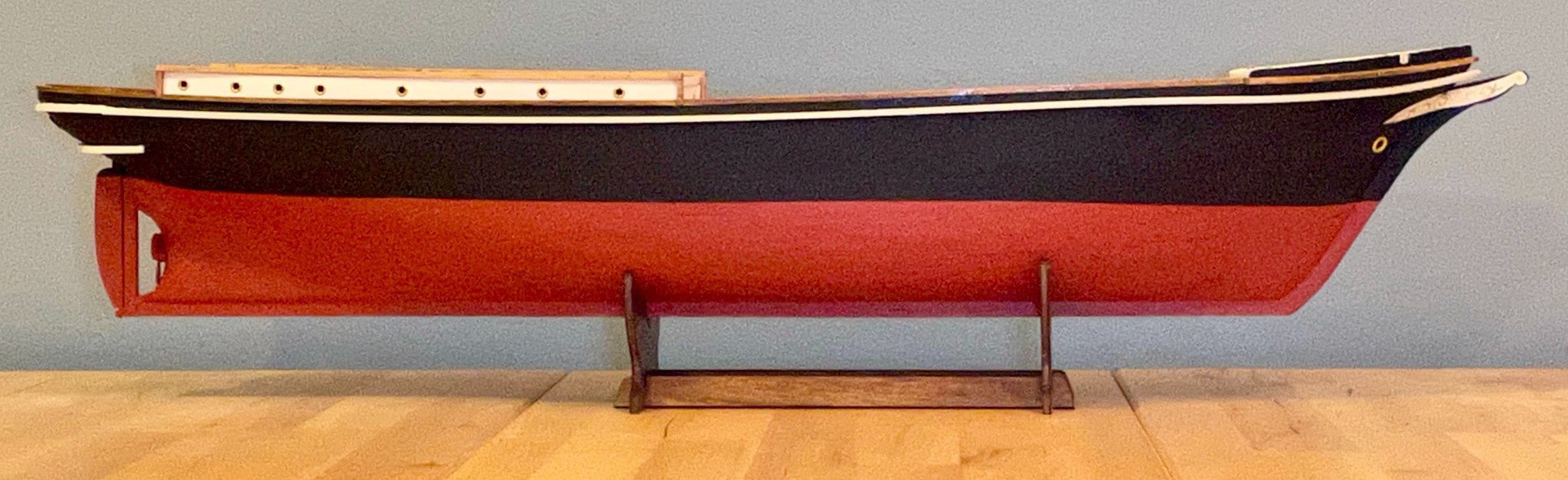
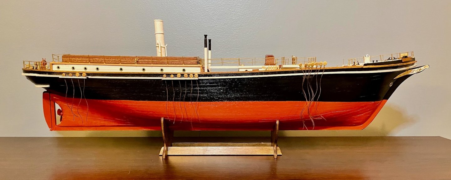
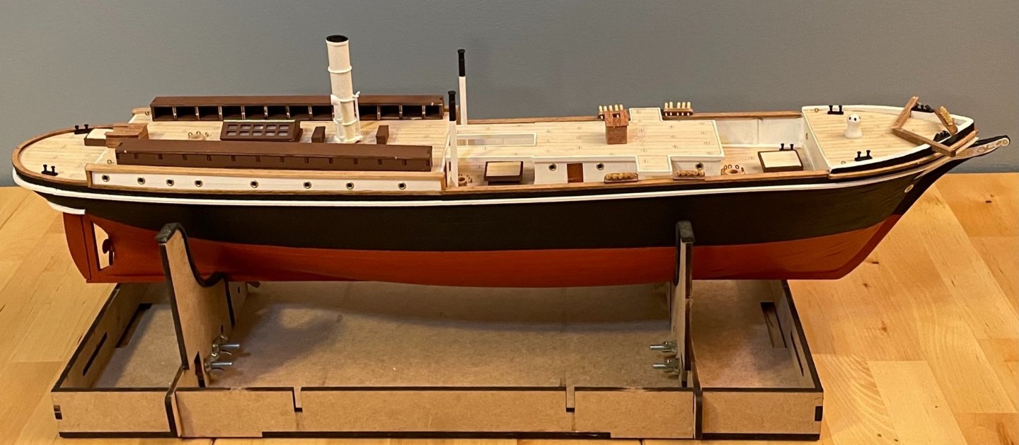
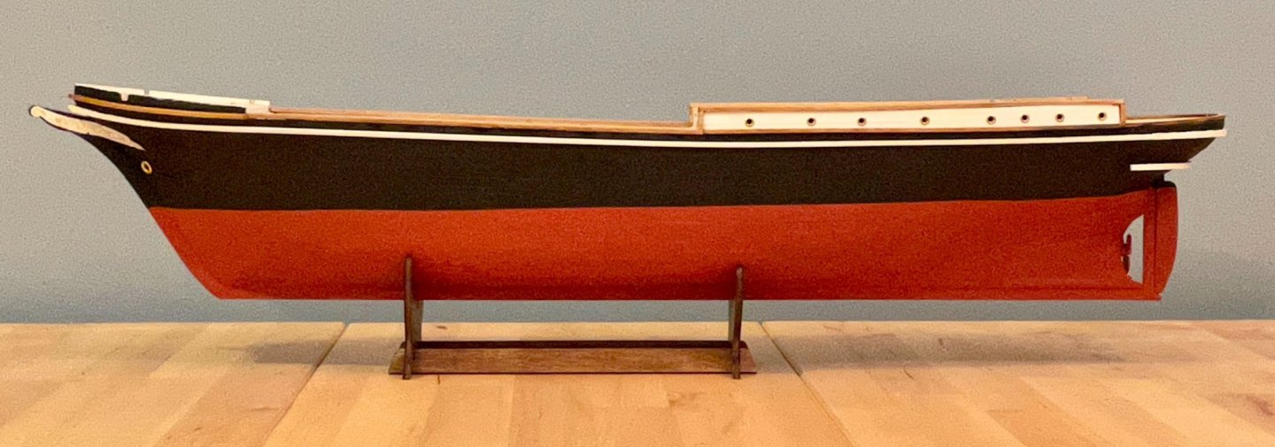
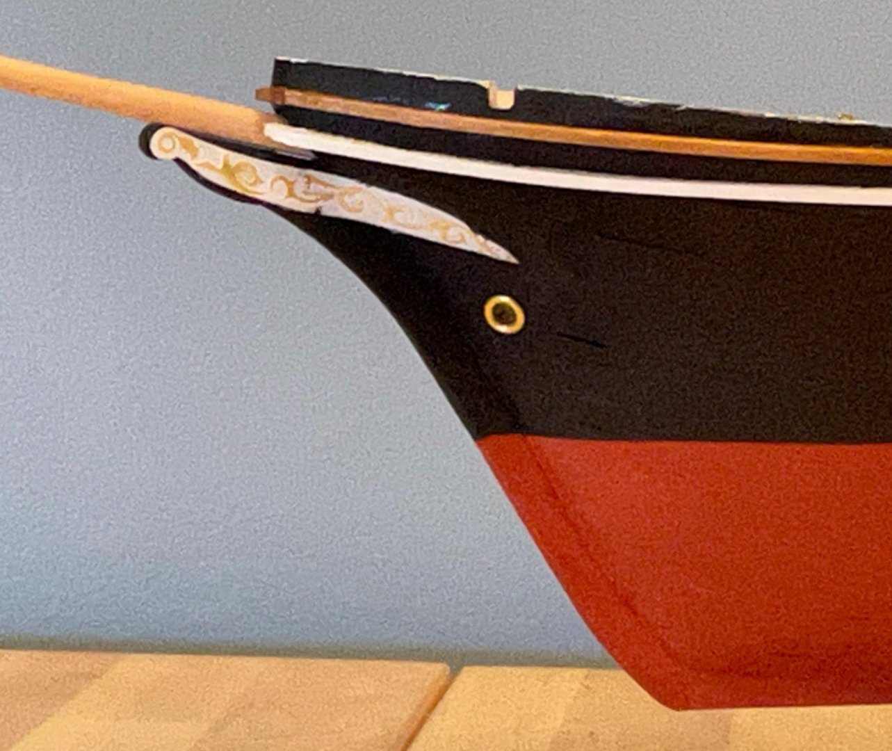
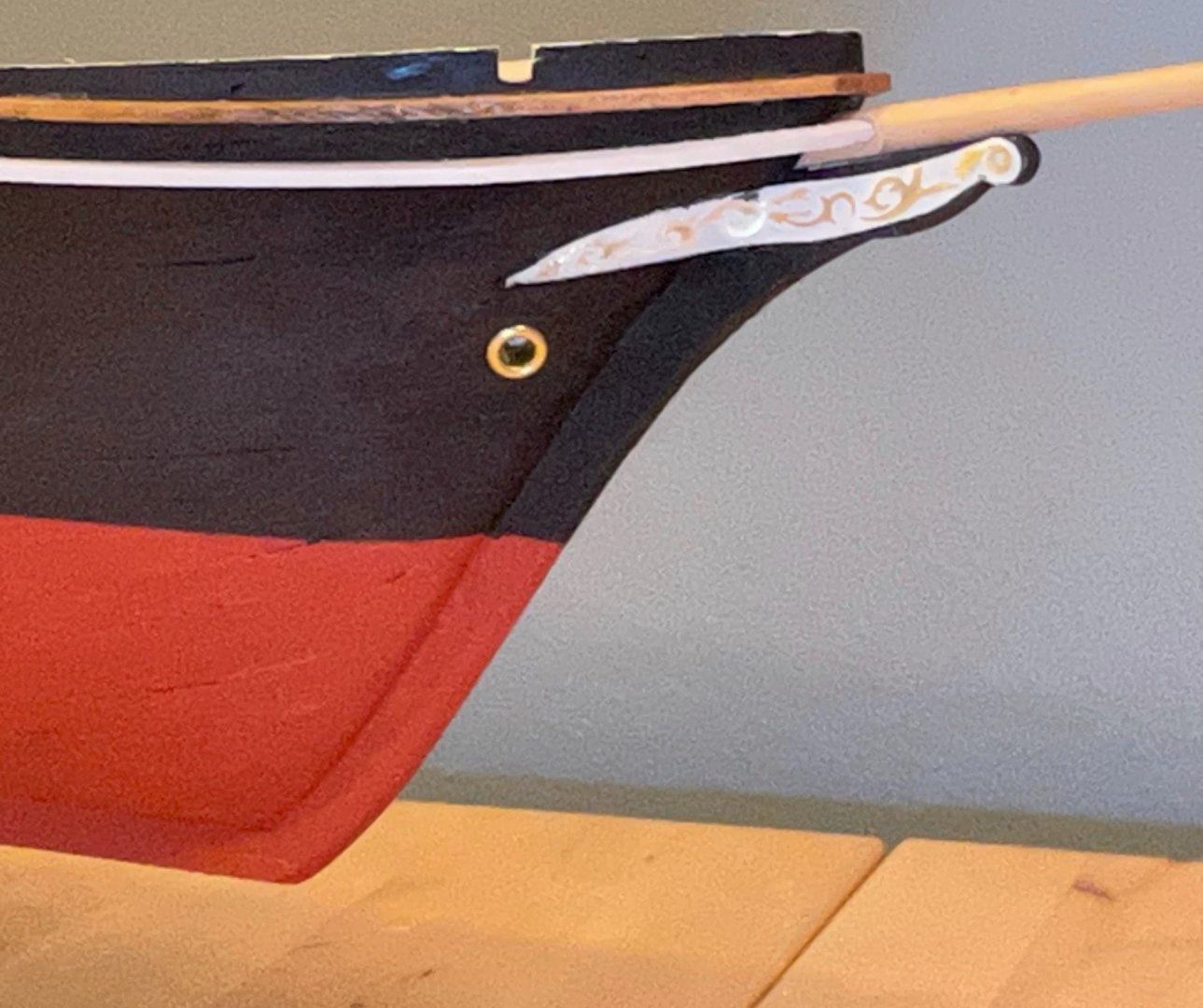
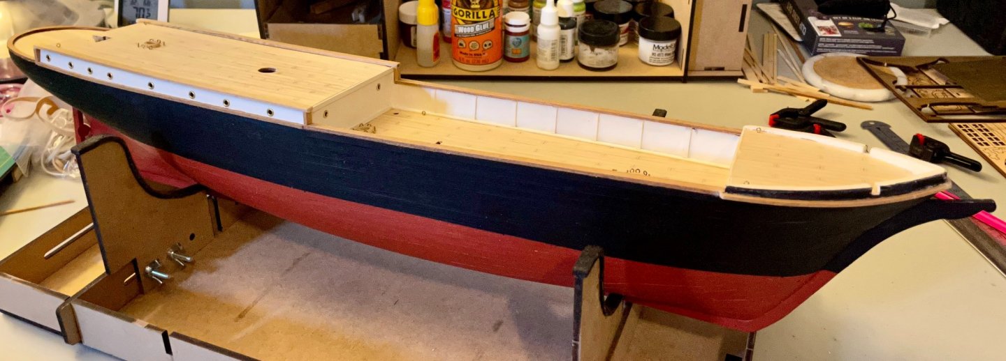
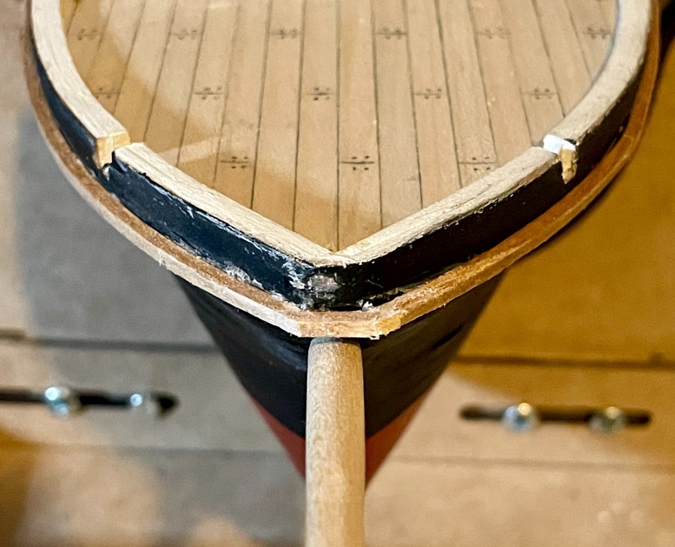
I have celebrated the end of my summer courses by devoting more time than usual to my Endurance and, I'm thrilled to announce, the hull is finished! So, some photos to celebrate. (My apologies for the graininess of the images...the ship is large enough it's giving me fits with lighting, distance, zoom, etc., especially since I'm just using a cell phone camera.) First, the profile shots. I'm generally pleased with the overall impression here. Some imperfections, of course, but since I've only been building model ships for about 16 months now, I'm satisfied with the progress of my skills. Next, the prow. The imperfections are a little more obvious here (argh...the misalignment of the hawseholes!). This area posed a variety of difficulties for me. To others building the kit, be prepared for challenges with fitting the rub strips and the forward rails. The brass decoration pieces were also particularly challenging for me, since I'd never worked with pieces quite like them (flat brass sheets that need to be bent to follow the curves of the prow). I added the bowsprit for reference in the two profile shots. And, of course, the iconic stern. The curved rub rails were again a real challenge for me. They still aren't perfect, but look fine if you aren't looking too closely! Next steps: I'm up to the M and N steps in the instructions, which focus the fittings for the fore- and main decks, including constructing the "Ritz" (the galley and dining saloon where the crew spent much of their time).


- 173 replies
-
- 10
-

-

-
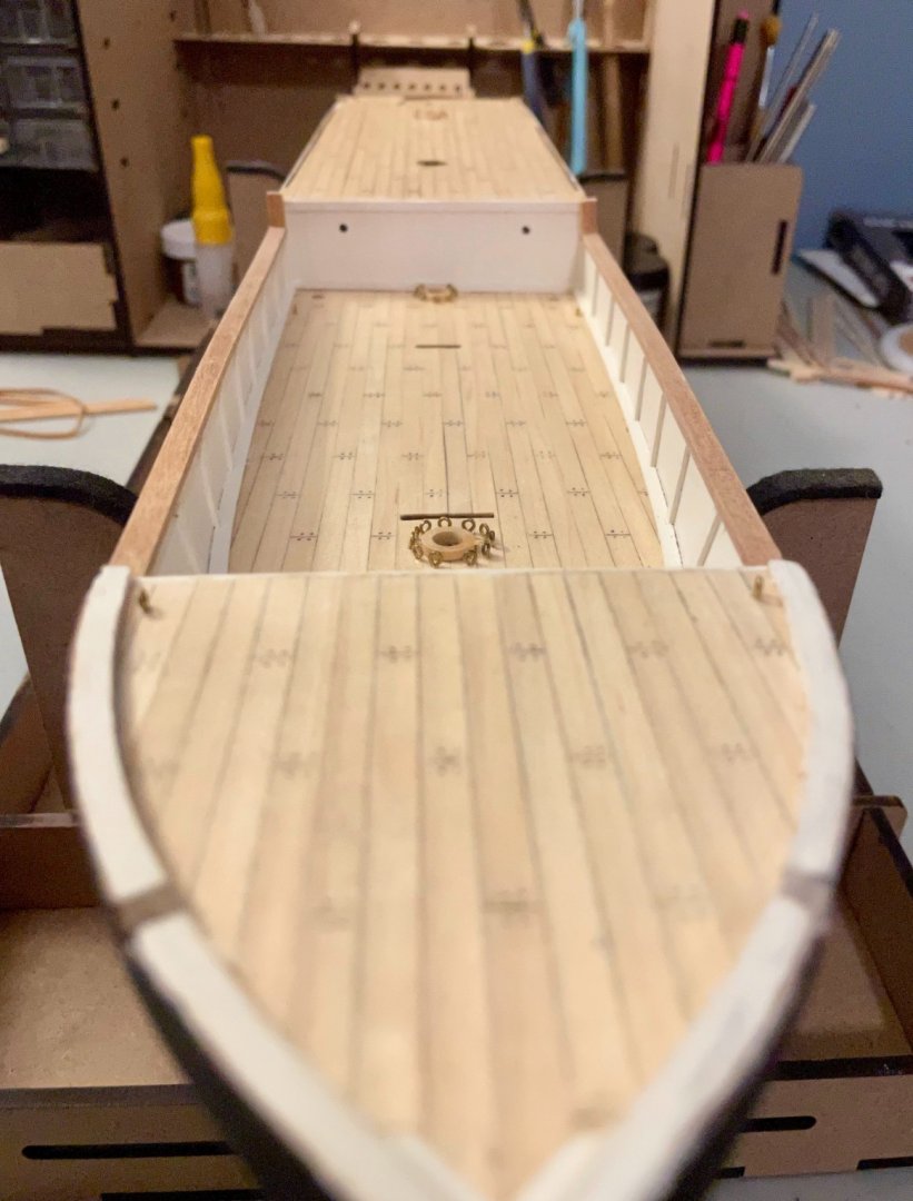
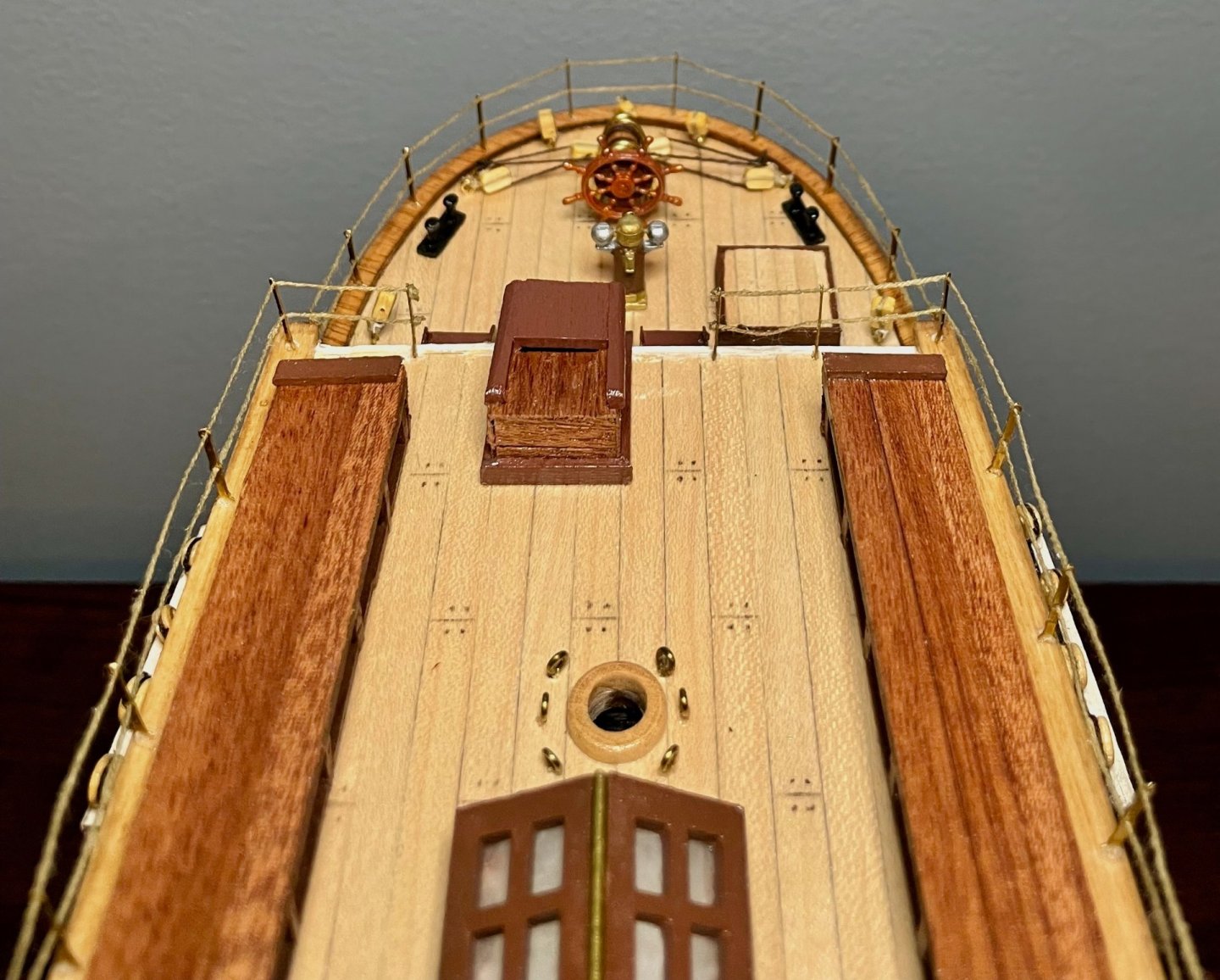
Hi Johnny, some helpful and interesting observations! I ended up using the eyelets provided in the kit, since some of my portholes weren't as round as I would have liked. But you're right that Hurley's exterior photos show that all of the portholes were simply cut into the wood, with no fixtures outside. For those looking to be more historically accurate, here are a few photos to better understand the windows on the ship: This photo of Schakleton's cabin (aftmost on the starboard side of the main cabins) shows some of the interior fixtures. There's actually another porthole in the photo, too, hidden behind the bookcase; zoom in to the second shelf on the right and you'll note that the porthole has been boarded up. (Side note: I wish this photo were a little higher resolution! I think I recognize a full set of the Encyclopedia Brittanica, several dictionaries and other reference books, Cassell's Book of Quotations, Whittaker's Almanack...I'd be curious to know what the other books were!) This photo of the scientists' quarters (aftmost on the port side of the main cabins) offers another view of the interior fixtures on the portholes. And a progress update. Apart from some clean-up, the rails are all on! I ended up needing to add one additional piece that the kit doesn't call for. Above the bowsprit, the foredeck is rather blunted and the forward rails wouldn't make that sharp of a bend. So, I sanded them off even with the flat part, then added a short cross-piece. Still pretty messy right now, but I'll finish cleaning that once the glue has firmed up (my sanding was a bit too vigorous and I had to reattach that piece...). Shown here with the bowsprit in place. Next steps: attach the rub rails, hull decorations, and the rudder.
-
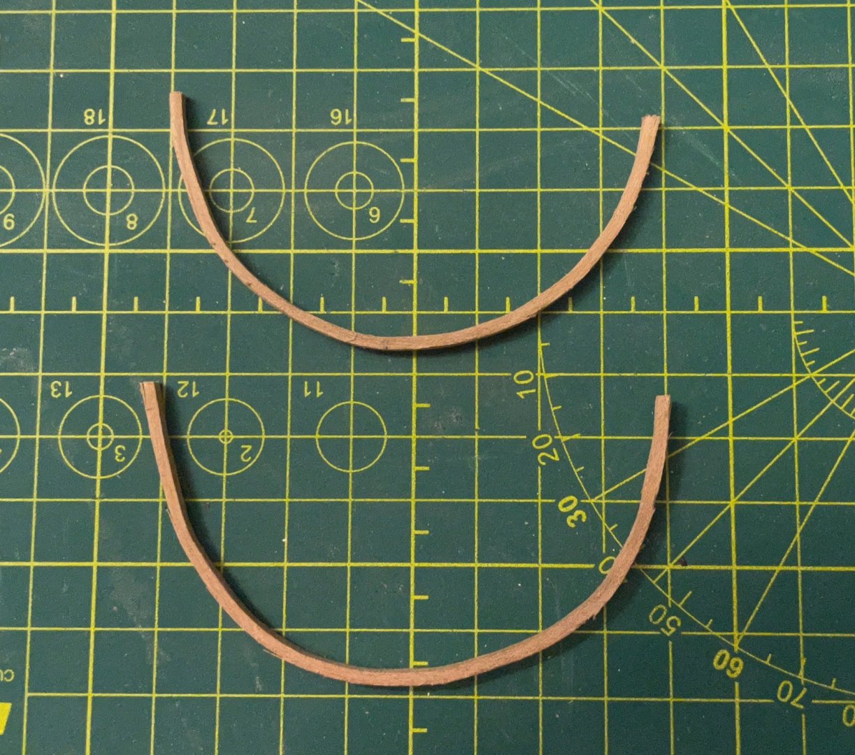
Hi Gerry, I haven't thought much about how I'll display the ship once she's done, since I still have a lot of time. At some point, I'll need to do that though—my other ships are moderately protected from dust and sunlight on a deep bookcase, but this project is far too big for that. I suspect I'll need to research display cases, but I just haven't invested much thought in that yet. And a brief progress check after some significant frustrations. First, I've remade and re-installed the rails along the main deck. The bulwark curves slightly, so I needed to use an iron to edge set them. Once the glue dries, I'll sand down the vertical pieces so I can install the quarterdeck rails. I've also had to scrap another piece of the rails (the second one that runs below the portholes in the cabin); I discovered this morning that it's a few millimeters short. ARGH! Second, I've shaped the trim pieces on the counterstern. These were a real pain; thankfully, I had plenty of leftover 2x2 planks from my last build. After breaking four pieces, I was finally successful with attempts 5 and 6 (though I still had to sand down some splintering on the larger piece). My final strategy was to cut them significantly longer than the final length, soak the pieces for about 30 minutes, then bend them with my daughter's curling iron. Finally, I used rubber bands to mold them on a can of vegetables overnight. Here's a shot of the pieces by themselves and in approximately their final position.