Rodolfo Bigoni
-
Posts
118 -
Joined
-
Last visited
Content Type
Profiles
Forums
Gallery
Events
Everything posted by Rodolfo Bigoni
-
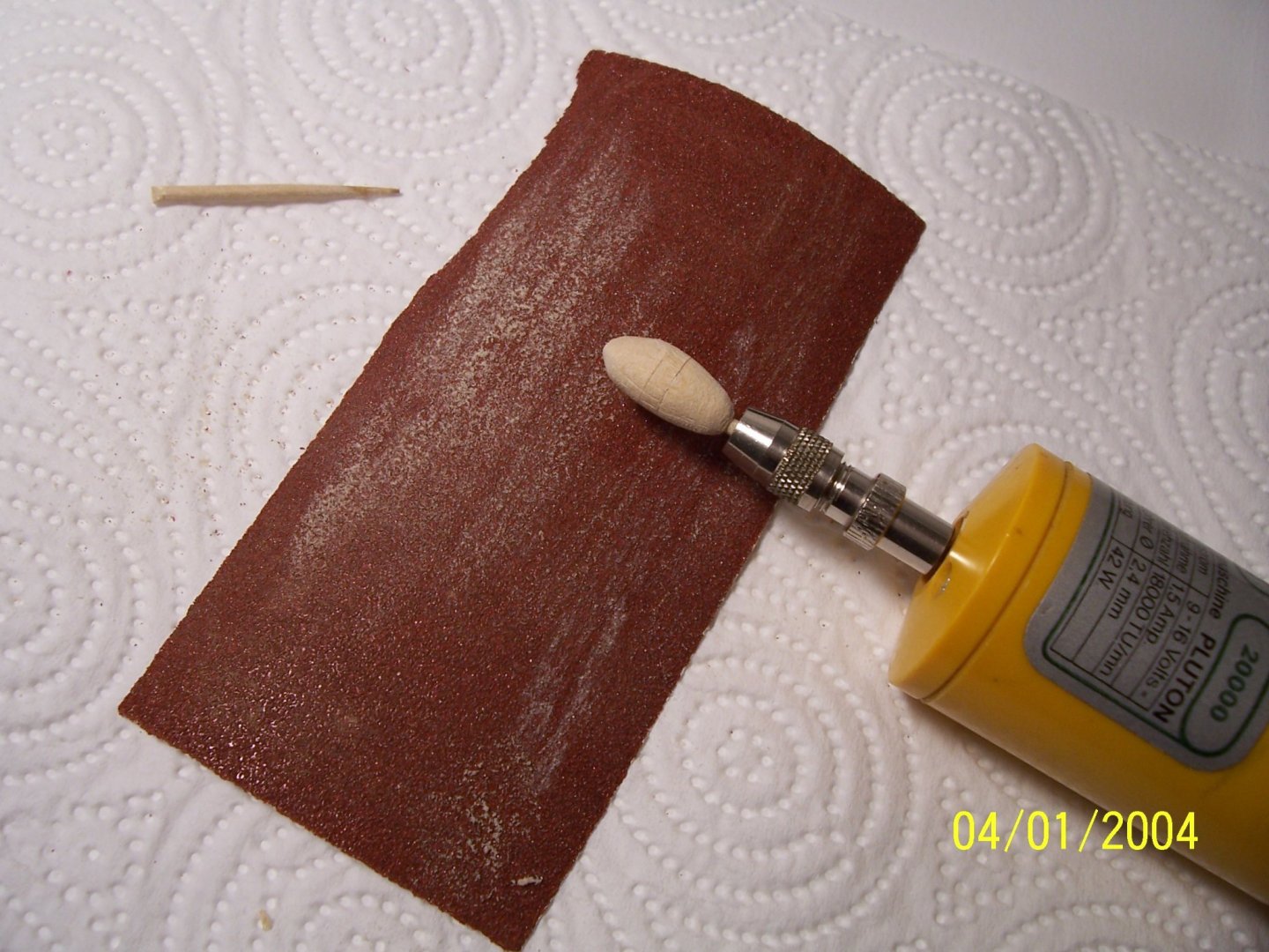
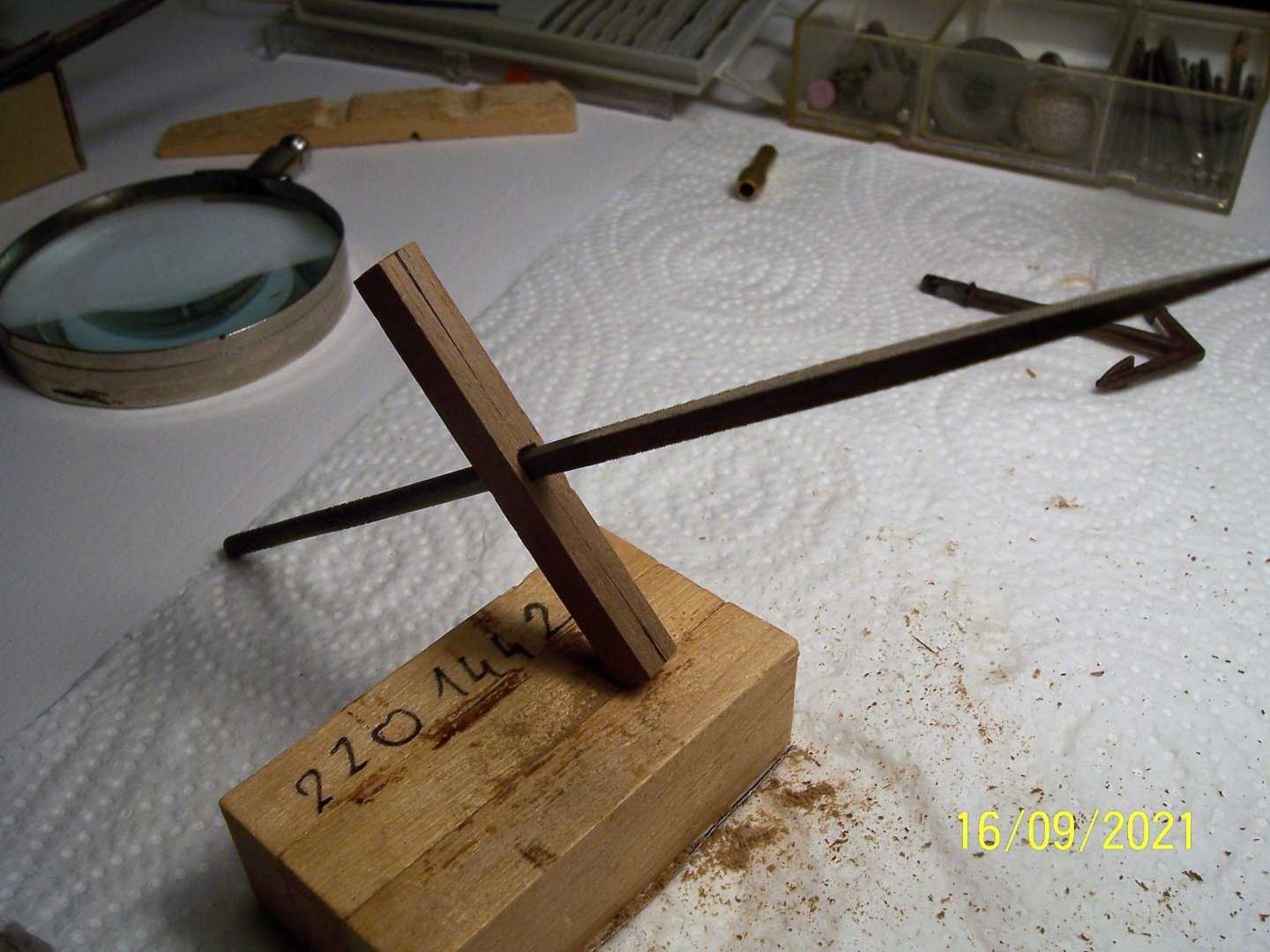
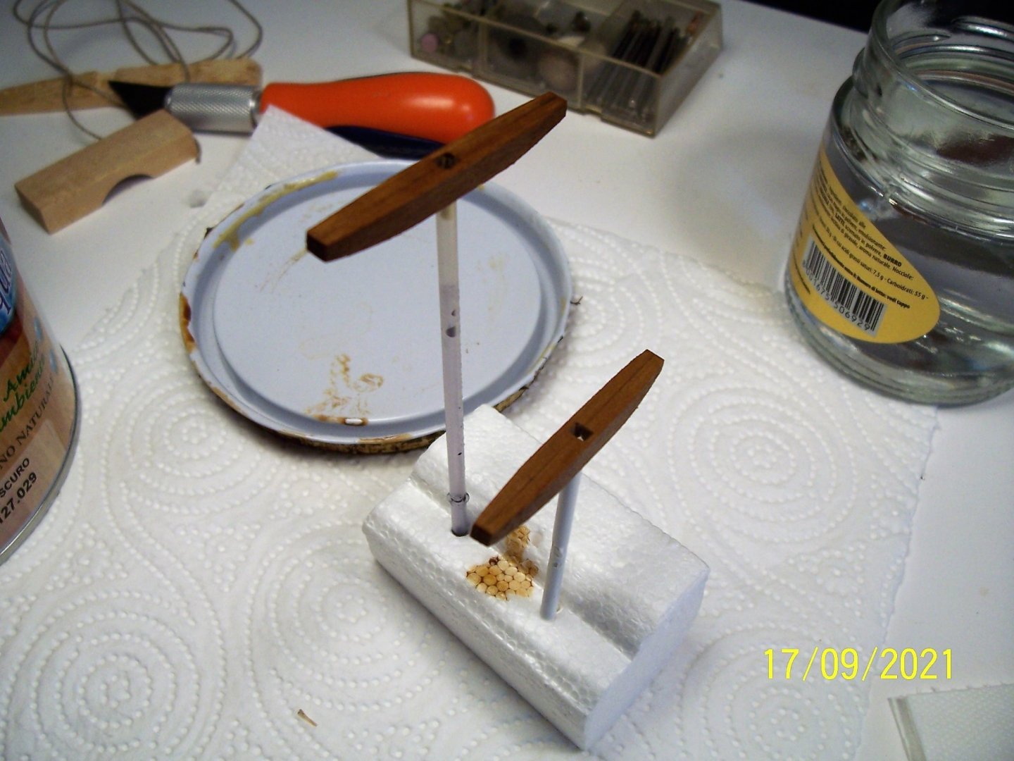
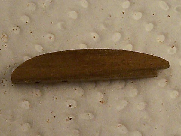
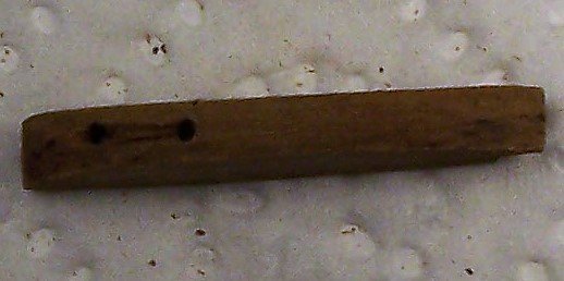
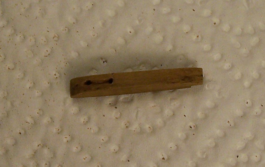
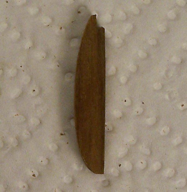
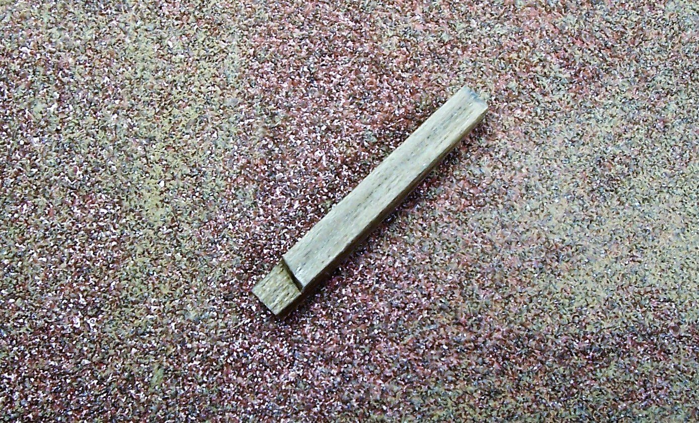
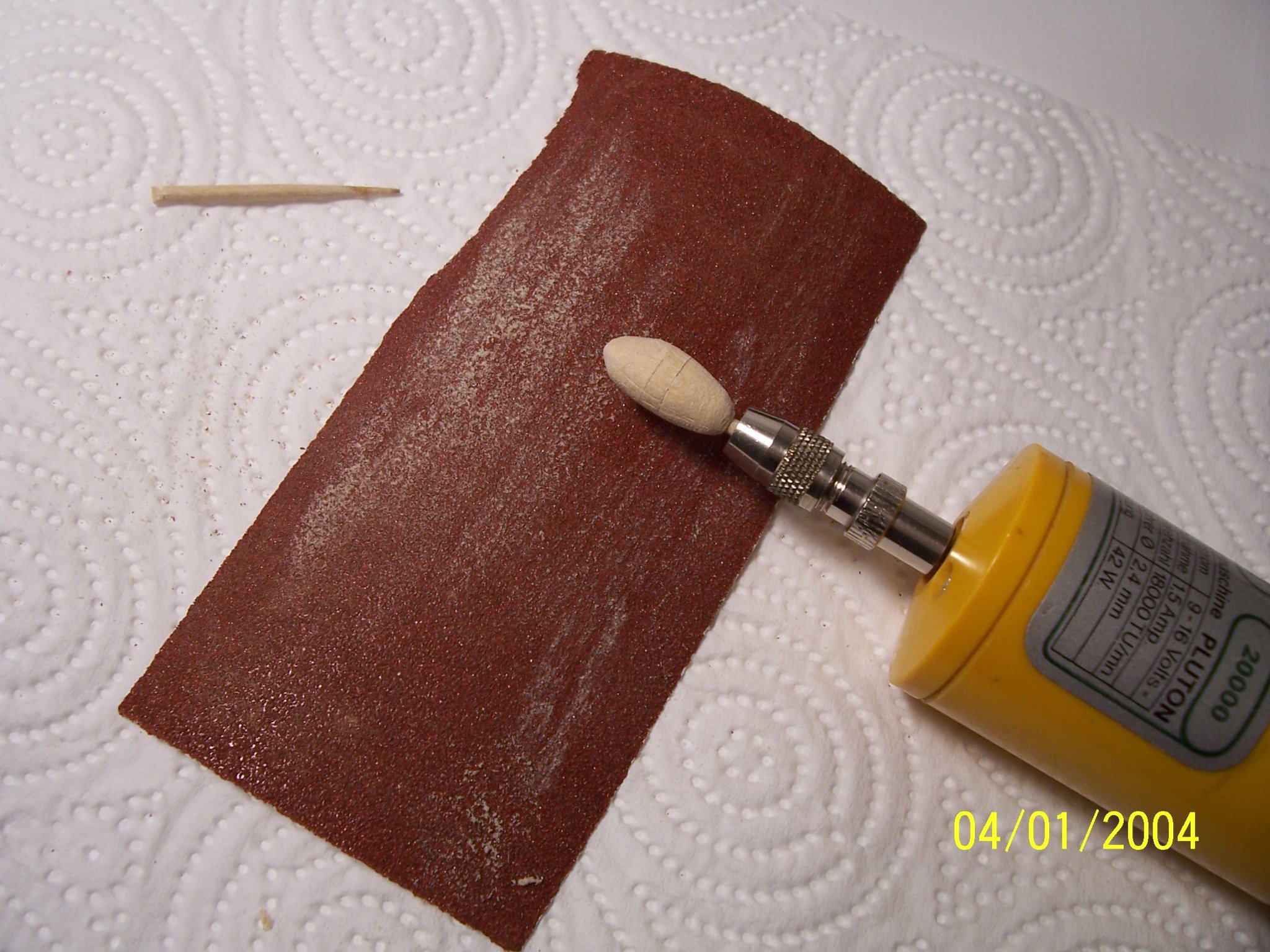
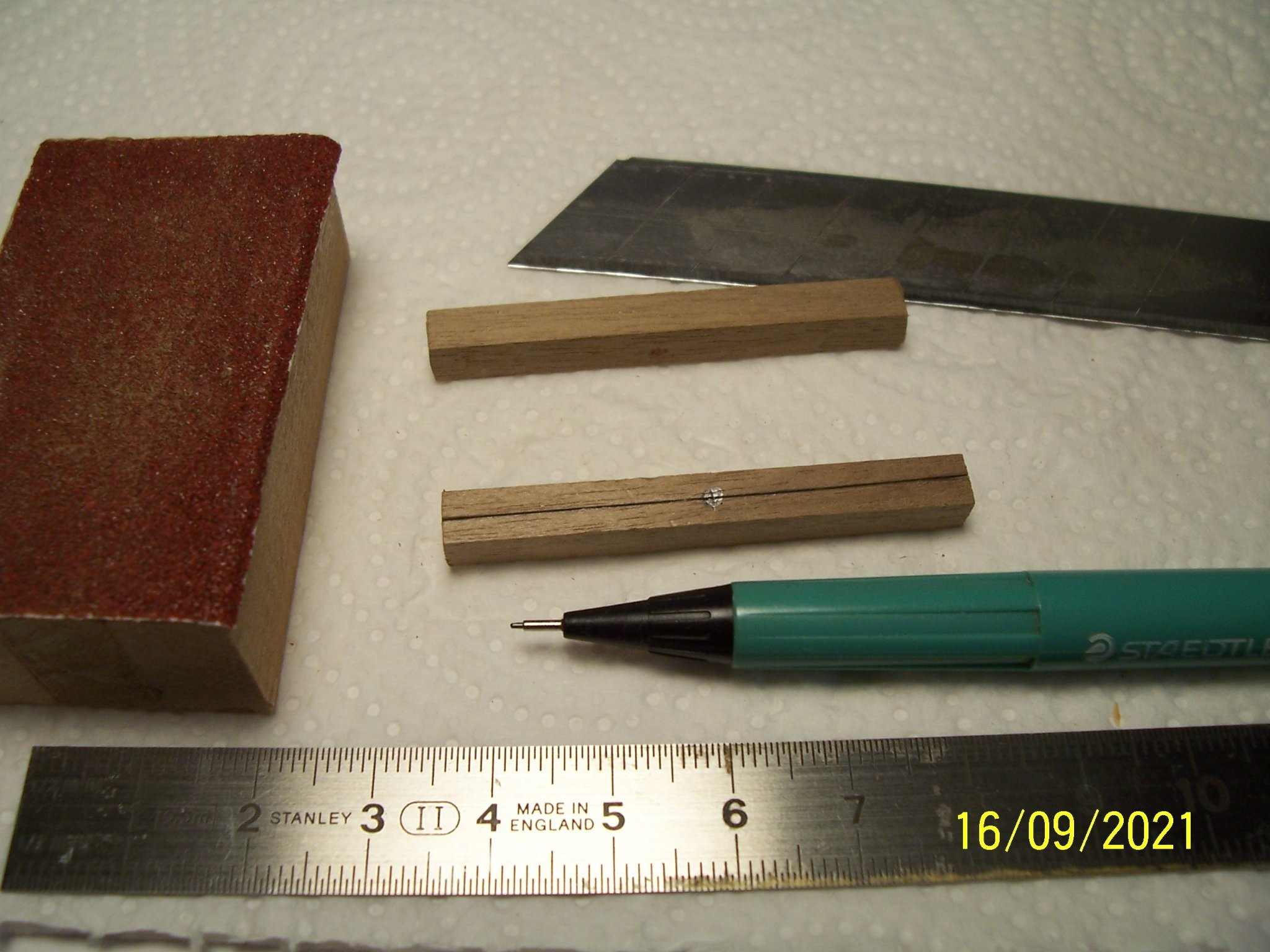
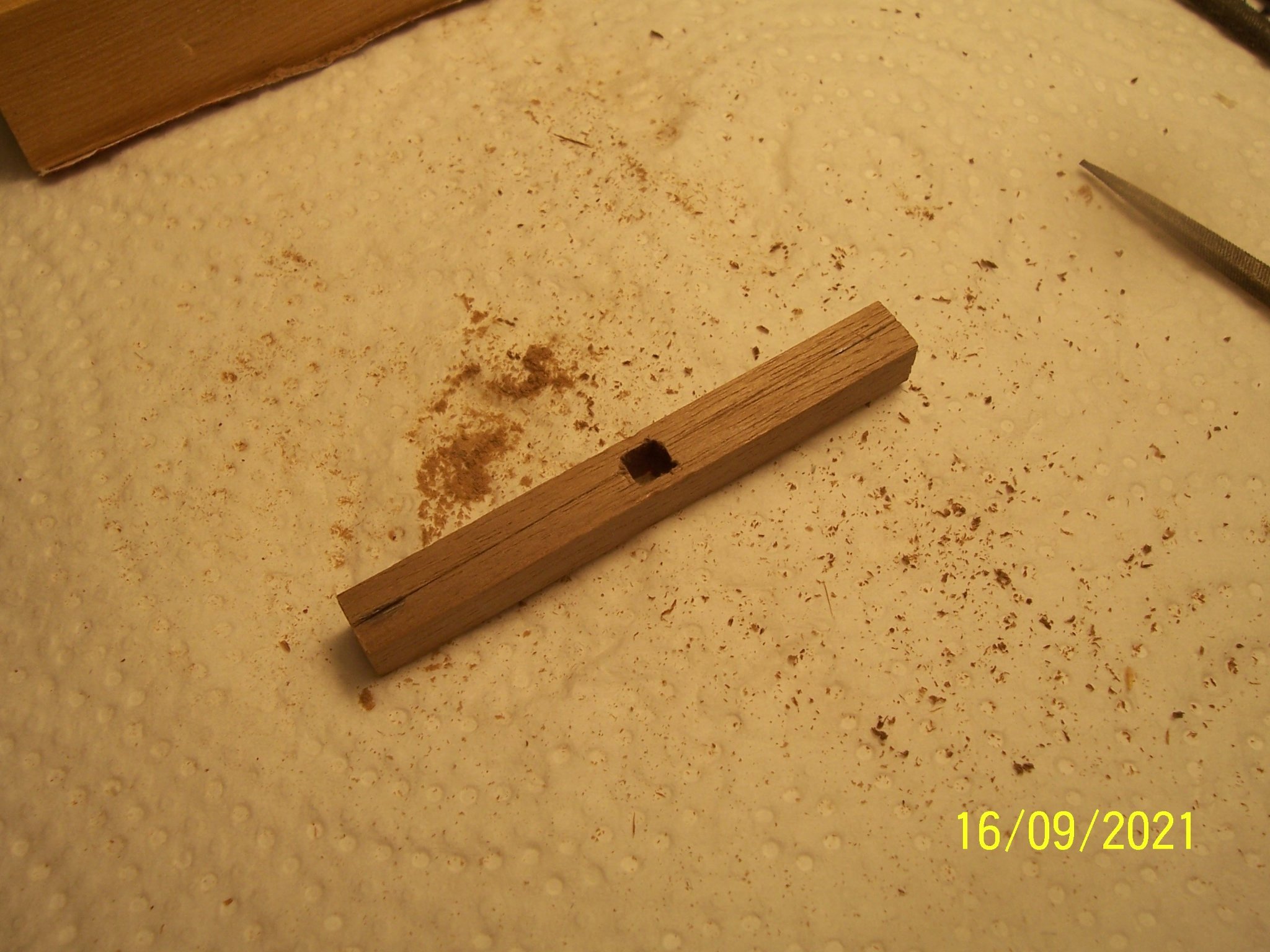
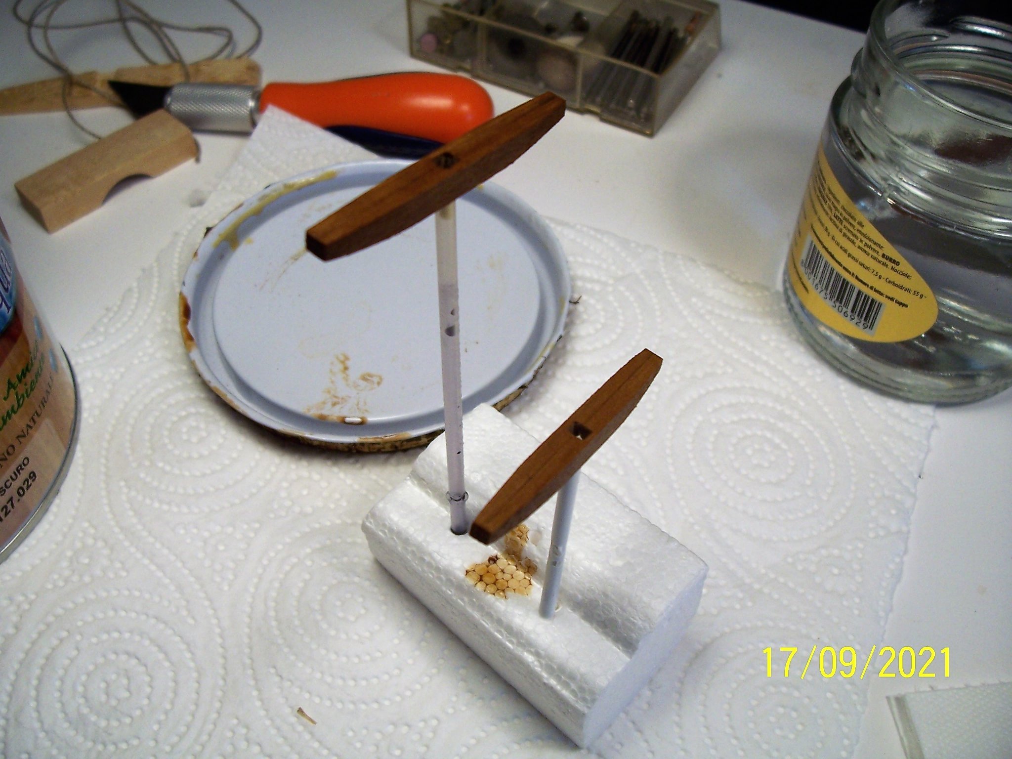
 To make the anchor buoys I used the remainder of the 10 mm rod used for the mast. Not having a lathe, I had to use a pencil sharpener to make the two cones and a small hacksaw to make the center disk. With a blade you can make vertical and horizontal incisions. Then they need to be drilled at the ends to accommodate the rings. The dimensions seemed excessive to me and I proceeded to reduce and shape with sandpaper and drill until I got a result that seemed satisfactory. Next step we'll finish this object. See you soon! Rodolfo
.thumb.JPG.4f686886e8b7a84752add7240f1a97e8.JPG)
.thumb.JPG.55b511dd0a7c8c73ca2a6ad04923bbef.JPG)
.thumb.JPG.8622cf43130e6234ceaa7d36134b14fe.JPG)
.thumb.JPG.af0166daf45e1501f48863b40b3fd19f.JPG)
.thumb.JPG.09f37d70728769c96ddc8668f0e243b2.JPG)
-
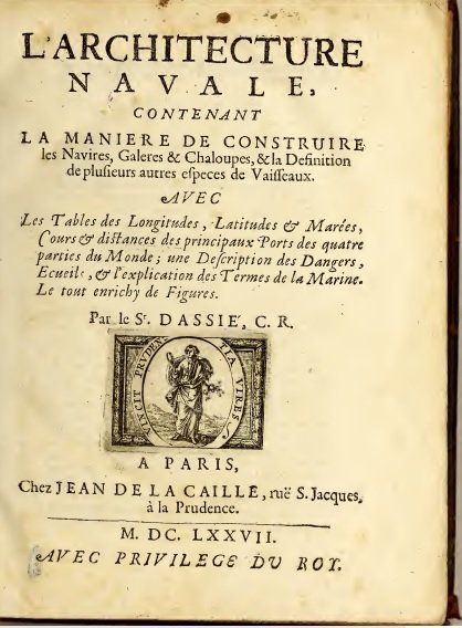
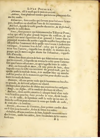
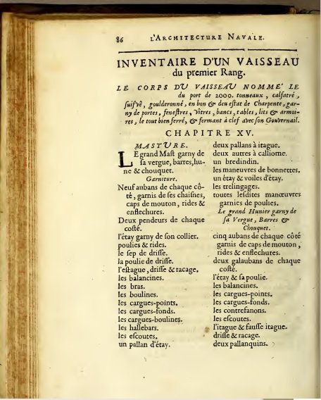
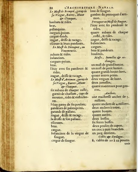
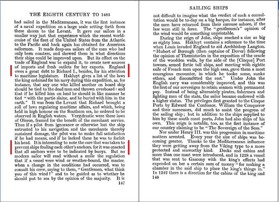
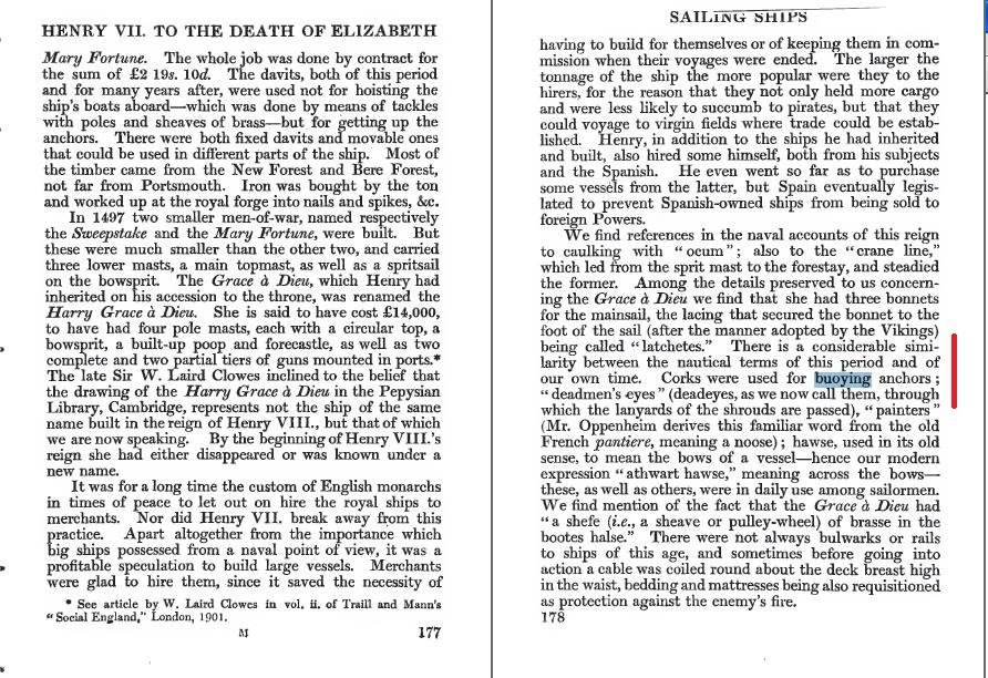
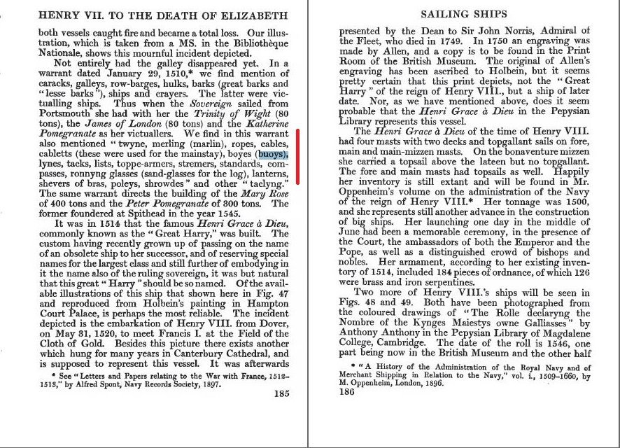
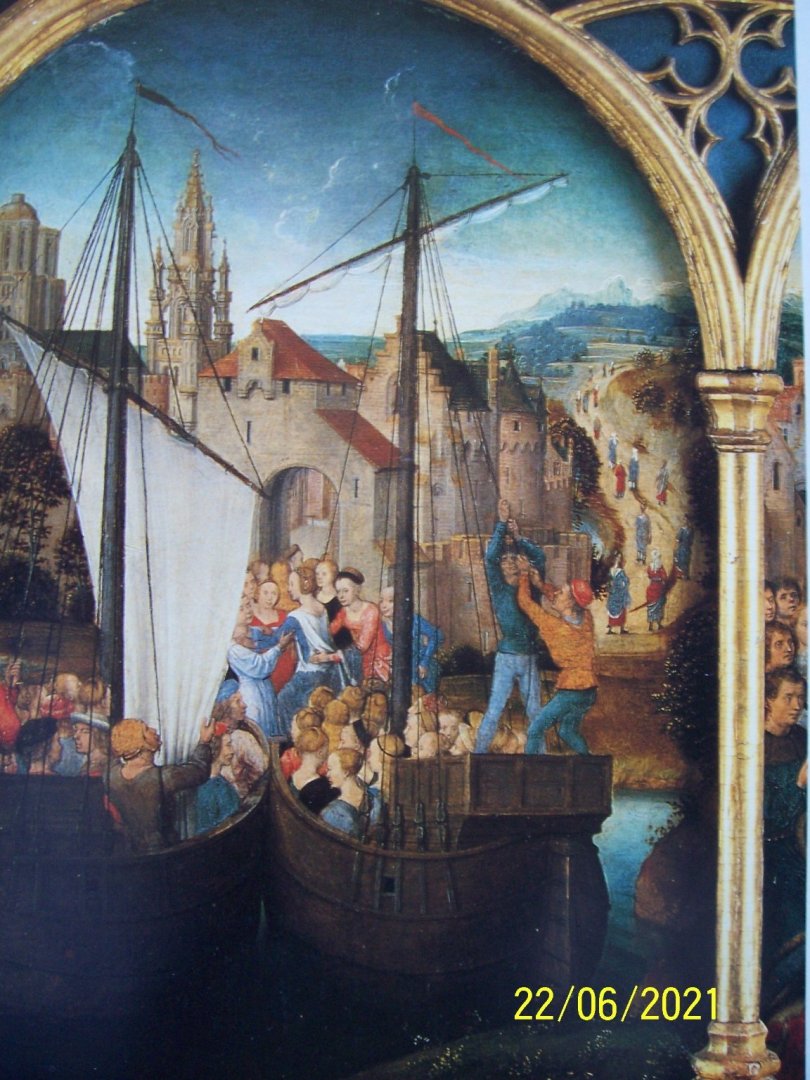
Thank you Steven and Patrick, and a warm welcome to our ship modelers friends! Regarding the presence or absence of anchor buoys on medieval ships, there is a certain discordance of opinions. Many say that since there are no images of these objects before 1700, they were not used in the fifteenth century. Regarding the historical fidelity of the buoys on medieval ships, it is true that there does not seem to exist figurative documentation at that time, but it is also true that they were probably considered of little interest, so much so that not even in a French book of 1677 they don't appear in the alphabetical list: They are not listed among Bordage, Bouge, Boulines, Brevils and so on. However, in the same volume "L'architecture Navale" by Dassié in 1677 there is a reference to the buoys, called "bouyes" (only one reference in more than three hundred pages, demonstrating the little interest of contemporaries). It is found in the inventory of a first-rate vessel, to which four buoys (quatre bouyes) compete for seven anchors in total: But in another volume, "Sailing Ship" - by E. K. Chatterton of 1909, there are some very interesting indications. On page 147 is written that anchor buoys were used to "prevent ship fouling each other anchors" at the time of Richard I and his crusade: The buoys are still mentioned on page 178, revealing the material from which they were made: To conclude, on page 185, buoys are listed as normal shipboard equipment, along with lanterns, etc.: I am not a historical, so I am unable to assess Mr. Chatterton's expertise and thoroughness, however, I am glad to have found something that supports my choice. And now we're going to build our anchor buoys. Rodolfo
-
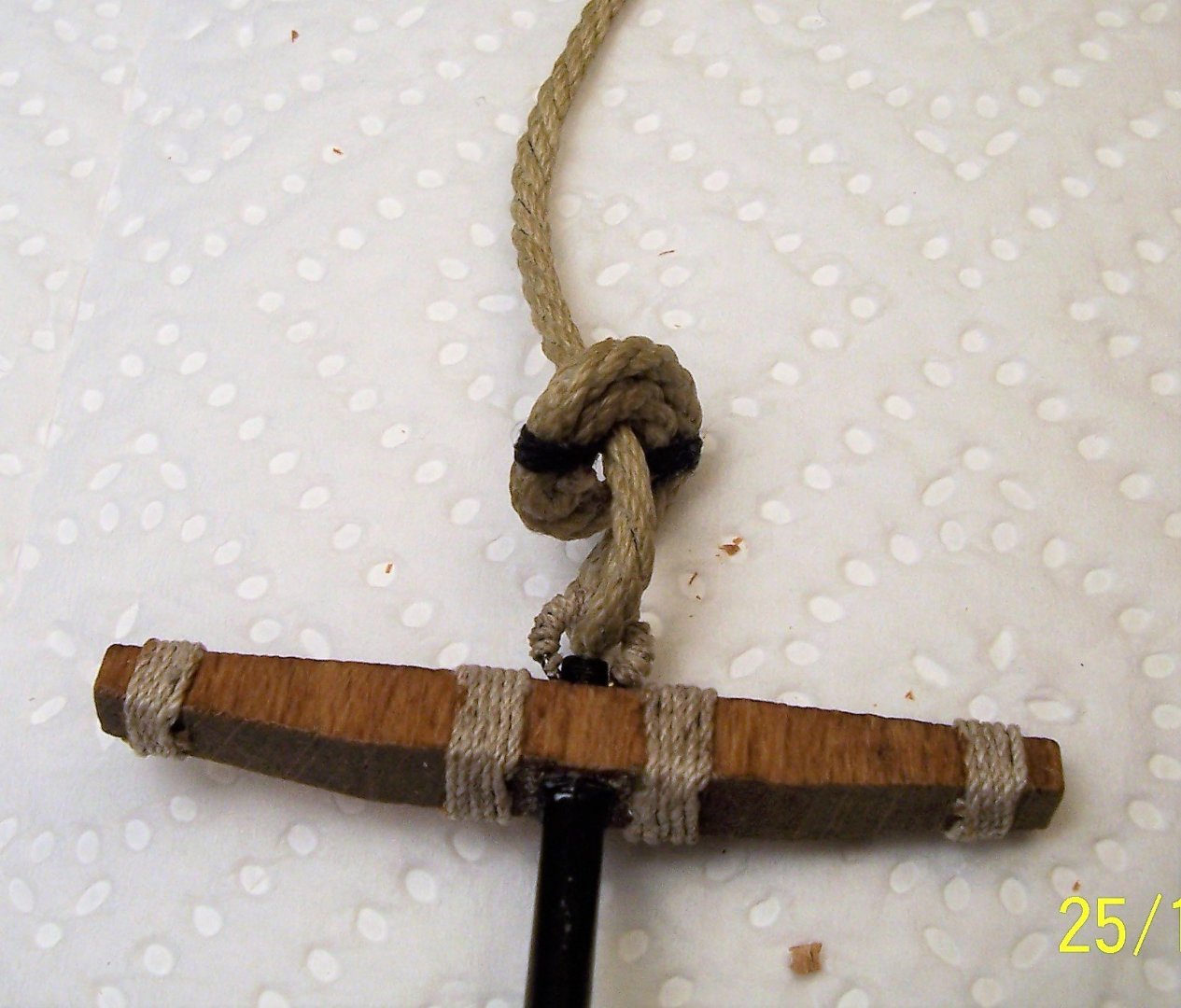
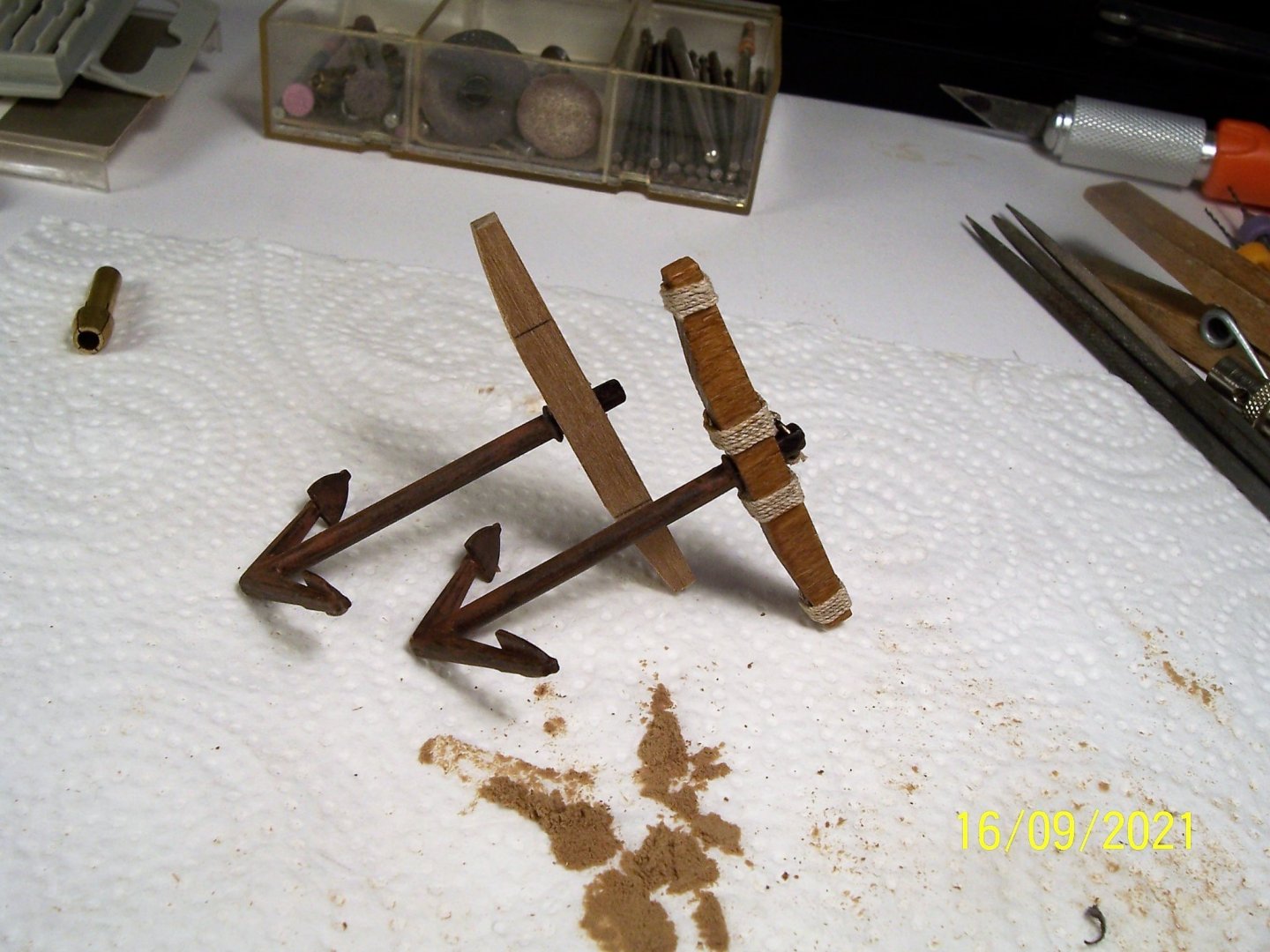
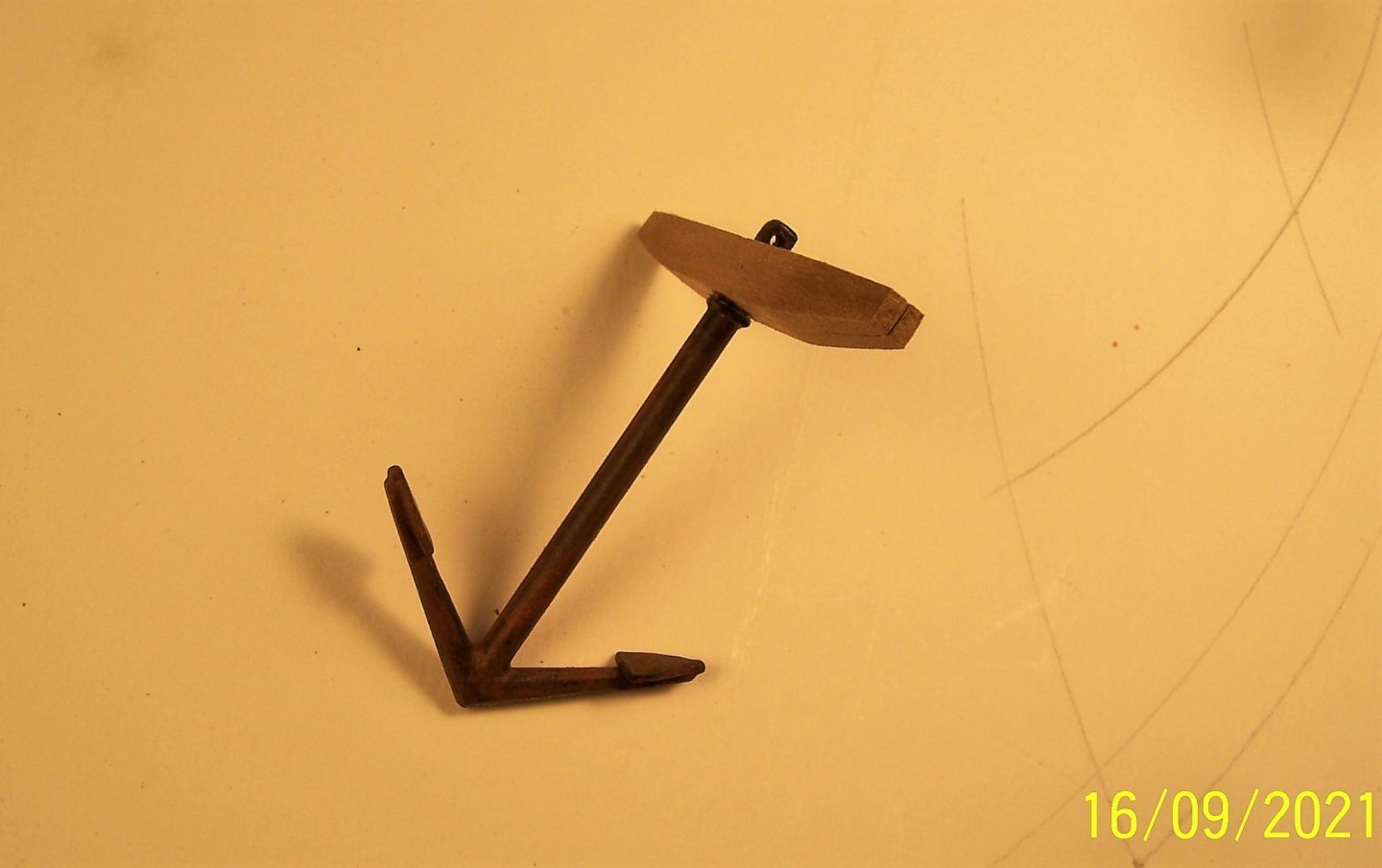
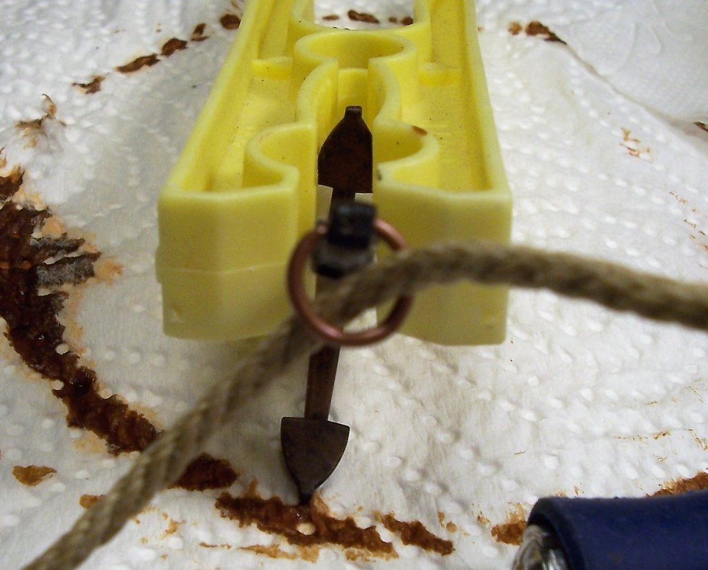
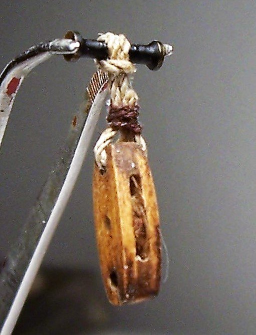
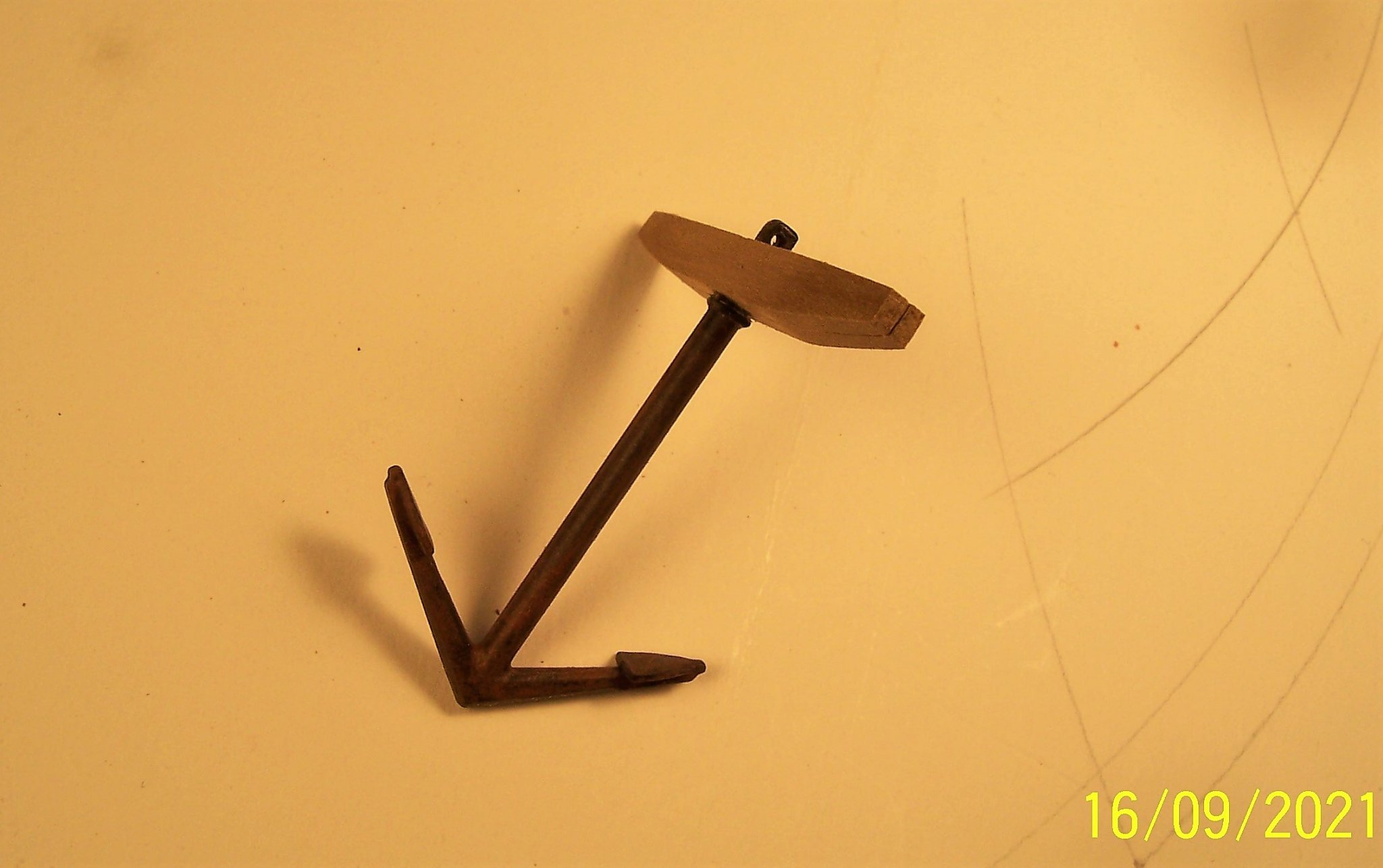
Since it is difficult to cover the closed ring with rope, I preferred to wrap some 0.3 mm grey wire around the straight rod, put a very small veil of cyanoacrylate adhesive, let it dry and then fold it: It's best to wrap plenty of wire to make several rings, as they can also come out wrong, especially the first ones: This is the final aspect of this rather important component: Connected the tow rope to the anchor using the system shown: Next Step: the anchor buoy. See you soon! Rodolfo
.thumb.JPG.d96df3514232707a3642f3c9895e7ca1.JPG)
-
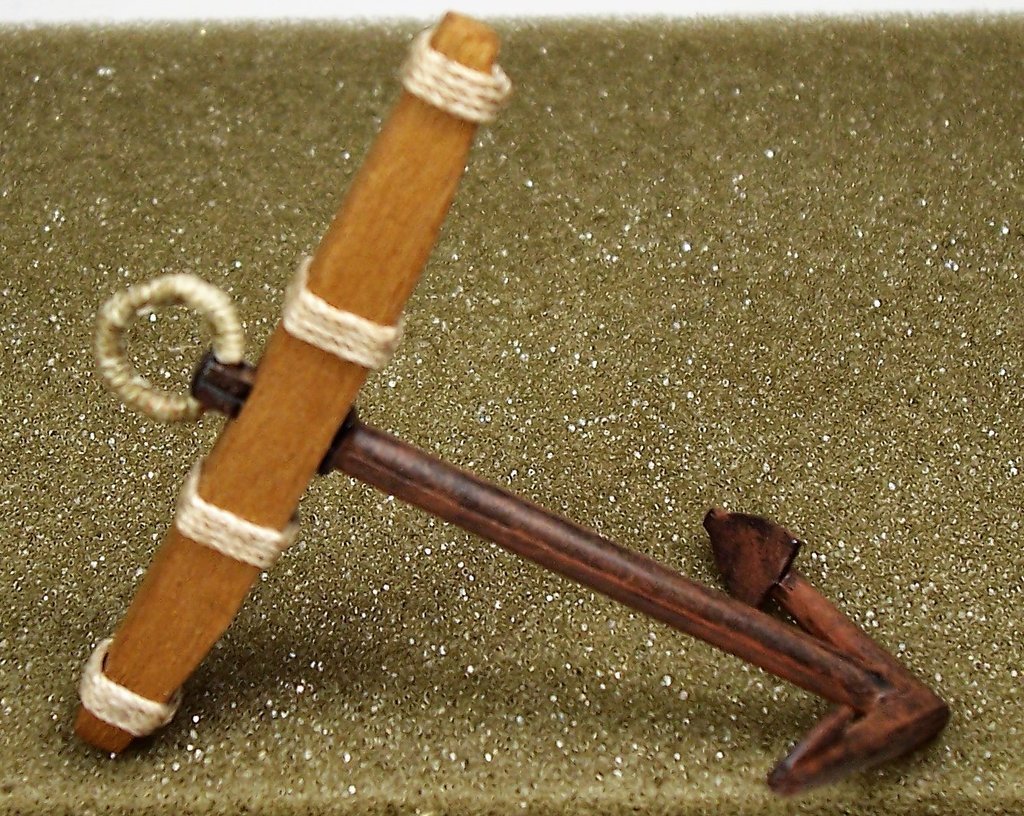
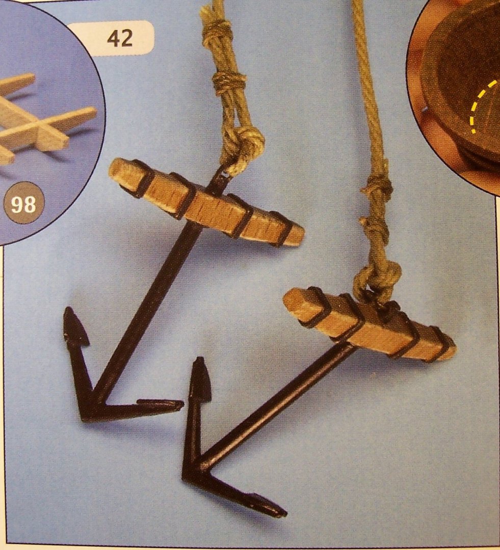
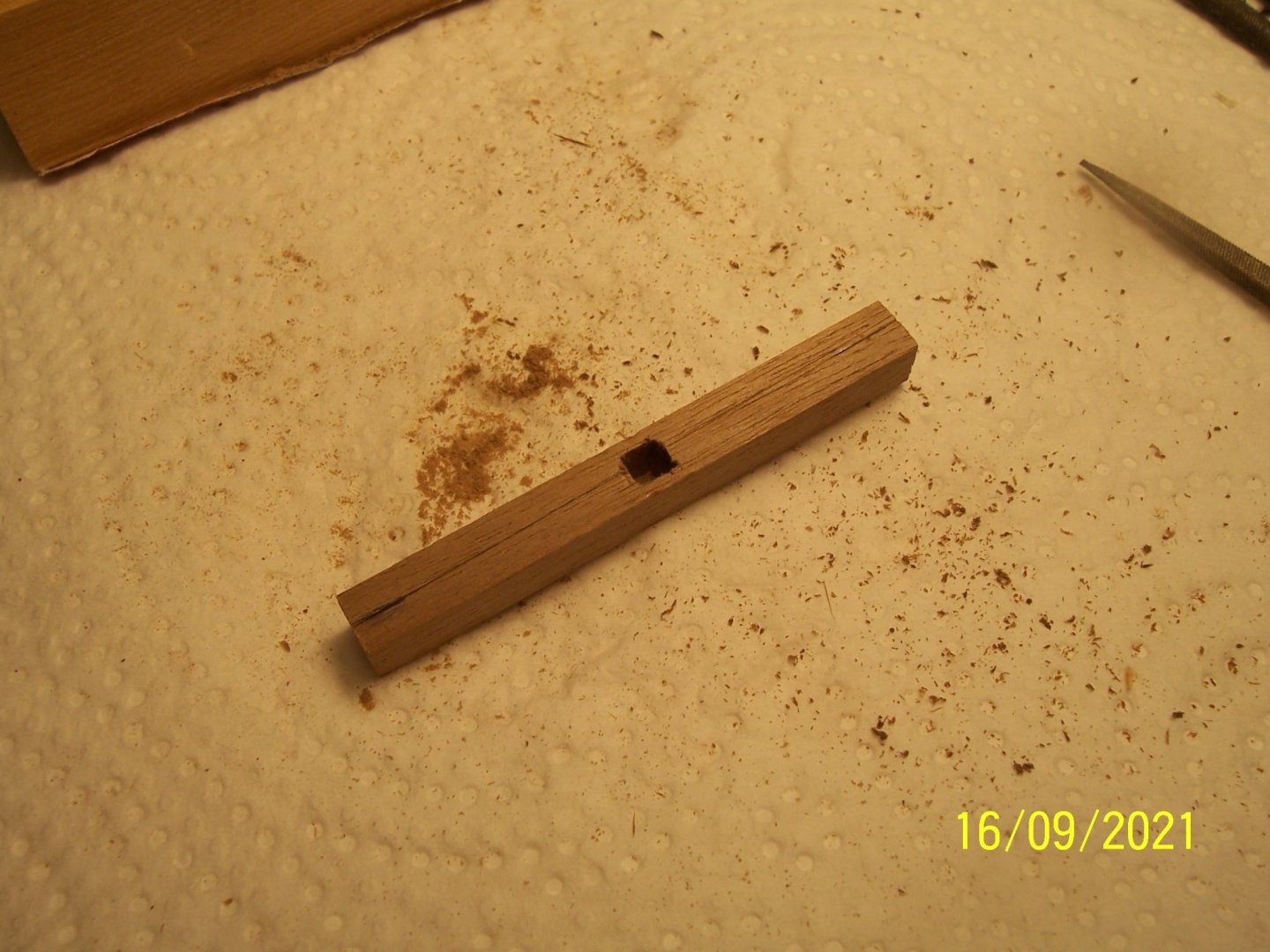
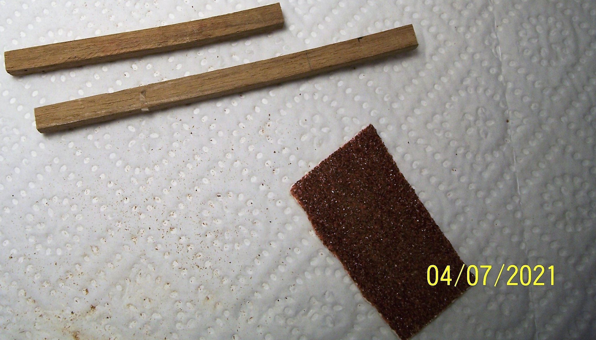
A sincere welcome back to all ship modelers! The anchors were assembled in the early days, while I was assembling the structure. I did some changes but now I don't like them anymore: The stock is a single piece, instead of two laths side by side, the veining of the side doesn't seem realistic, the top and bottom are unnatural, for the bindings I used a too large rope and the palms have an unreal relief due to the joint of the molding. First I filed away the relief of the palms, then I painted the metal with matte black and a layer of rust: Since I didn't have two 2.5 mm thick laths to couple, I used a 5.1 x 5.2 lath, drilled it in the center, engraved in the middle and shaped it: The bindings on the stock are made with a smaller diameter rope than on the previous anchors: The original anchor ring seemed too narrow for the large cable supplied by AMATI, so I made a new one with a 1 mm brass rod, bent over a 4.85 mm screw shank: However, it is difficult to cover the closed ring with rope. In the next post we will complete the anchor. See you soon! Rodolfo
.thumb.JPG.3e6d3af4b4b985918acd6f9cc7796157.JPG)

-
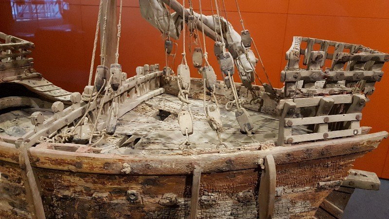
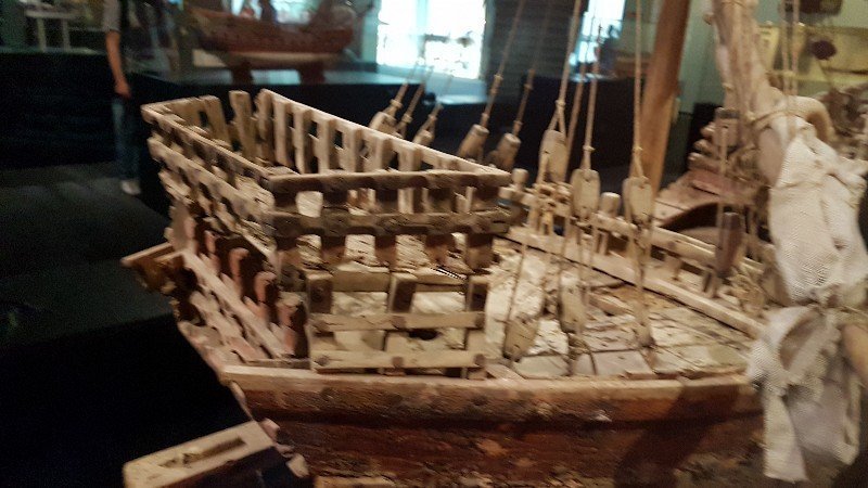
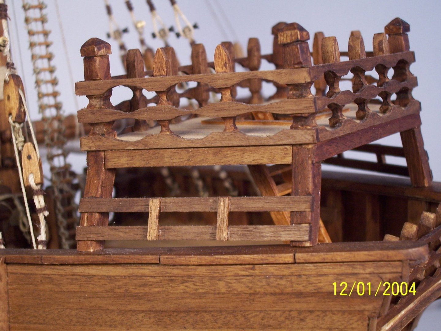
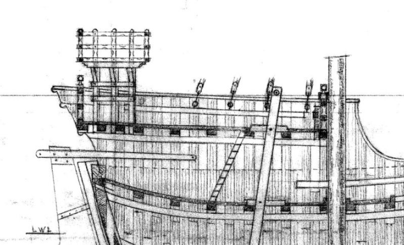
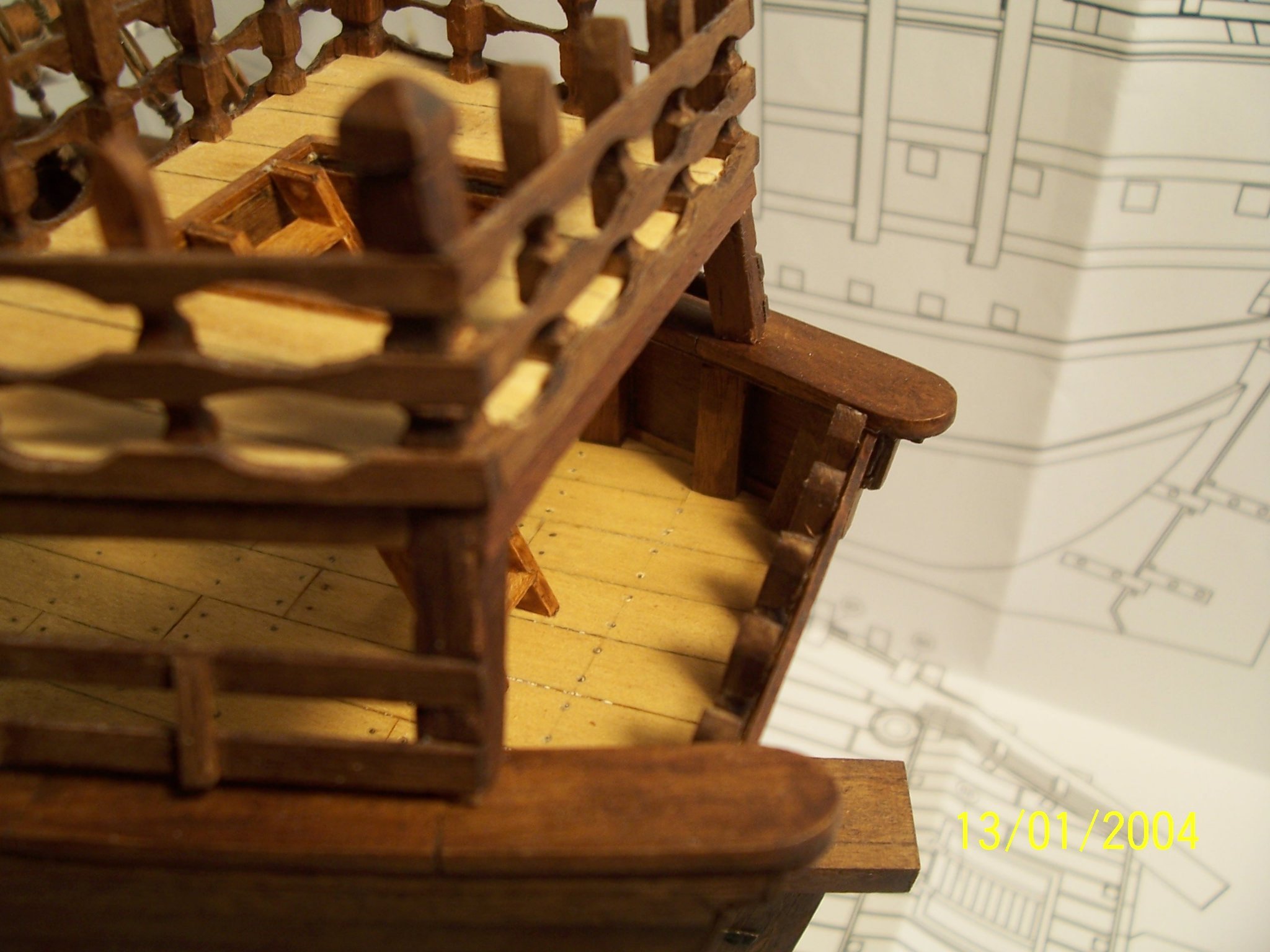
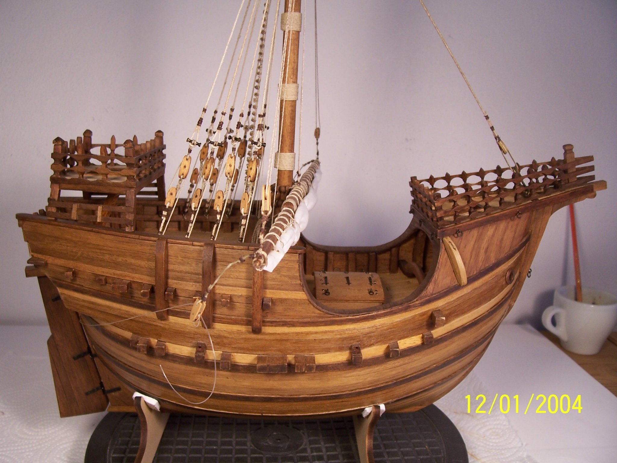
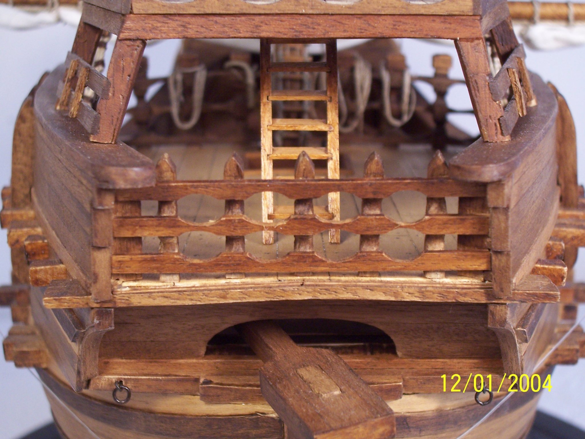
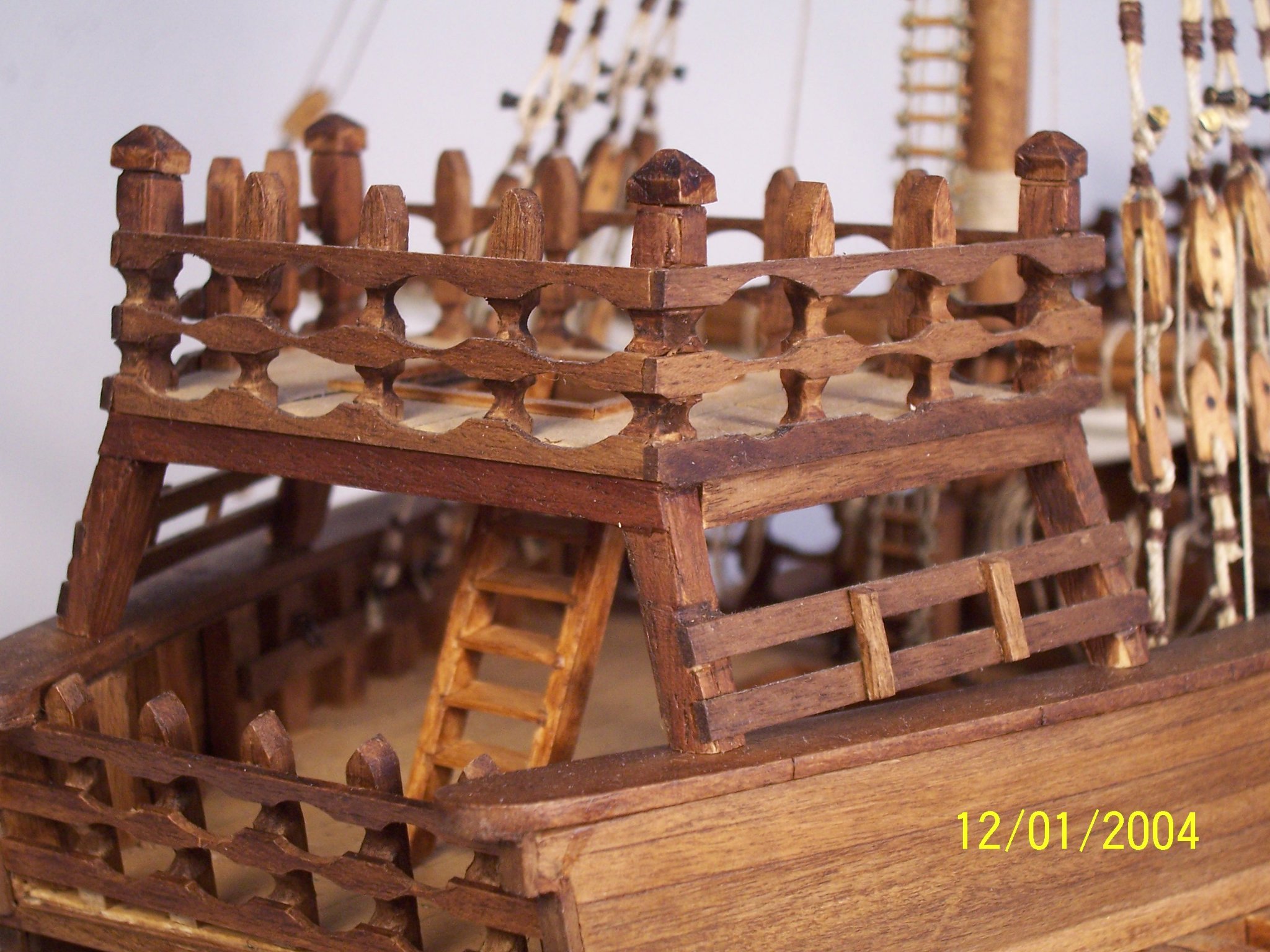
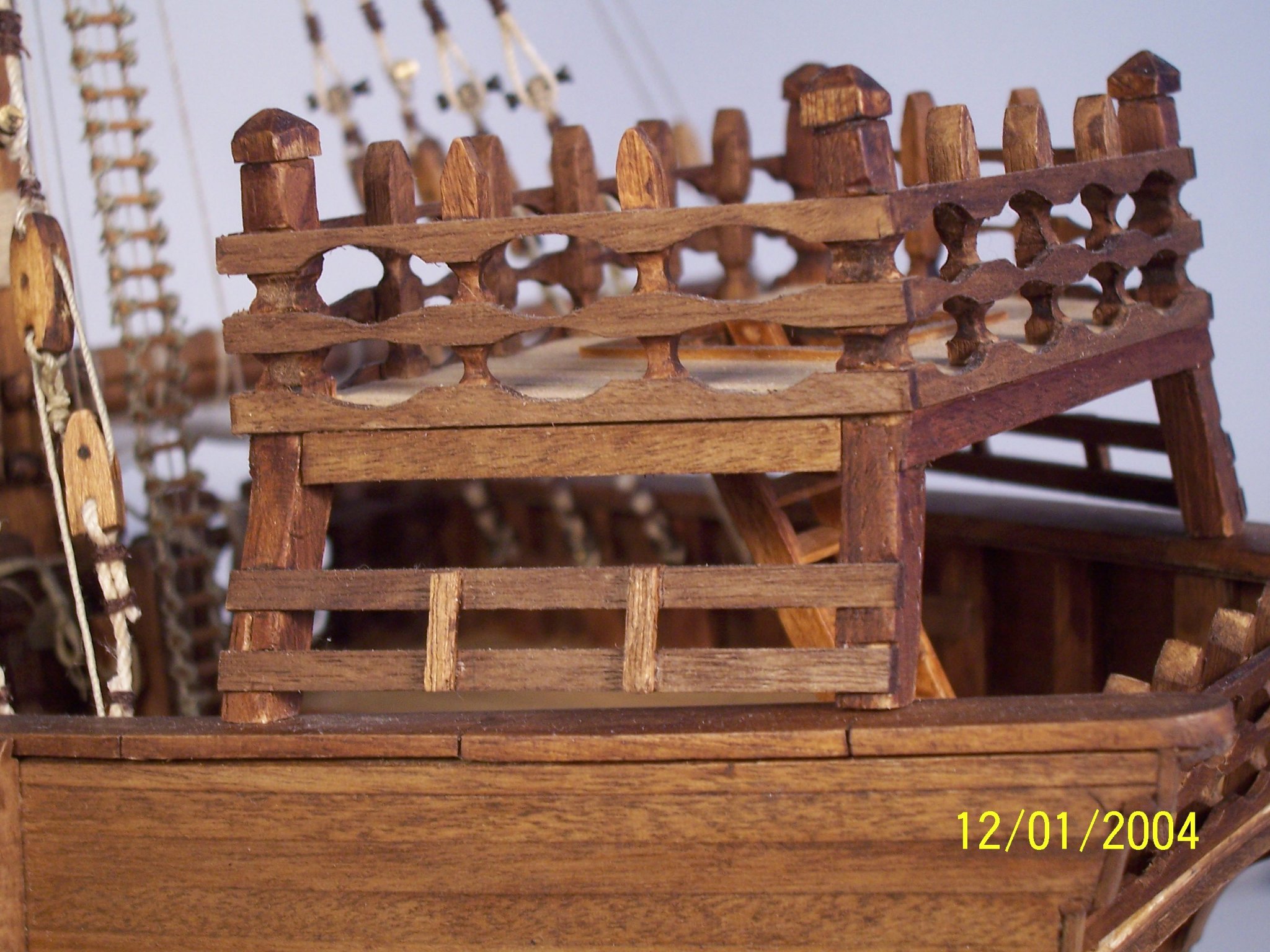
In truth, the stern castle of the Nao of Matarò is more displaced towards the stern, it is also narrower and has three supports per side, instead of two: We can see it is clearly close and inside the stern handrail. Because the Nao does not have visible stanchions, since the sides have been inside and outside planked, it can be deduced that the supports of the castle are in the interspace between the inner and outer planking: Unfortunately, in my model, I was forced to the solution previously illustrated by the initial setting of wanting to lengthen the deck aft (see post # 5), combined with the insertion of false stanchions halfway between those protruding from the frames. At this point the alternative was to move the castle aft, making it lean on the mainrail (unrealistic) or put it where it is now, giving the impression of bearing on the stanchions. I preferred the smaller evil: which after all, is not very different from what the instructions suggest: One solution might have been to add additional stanchions under the mainrail, but space isn't too much and perhaps the vision would have left something to be desired....Obviously, with hindsight, I would make from scratch a stand-alone structure for the castle, with the mainrail prepared with the appropriate slots for the supports; now for me it's too late ... See you soon! Rodolfo


-
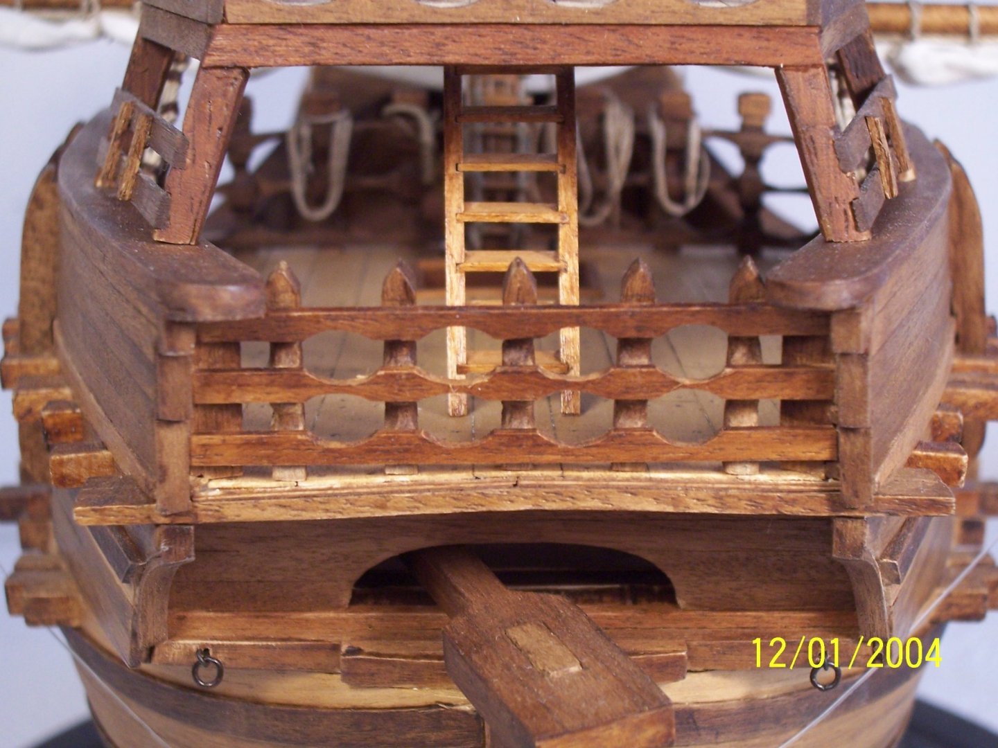
A warm welcome to all modeling friends! The sterncastle was already prepared previously (see posts #67). The AMATI instructions recommend making four square incisions in the main rail, within which to insert the bases of the castle supports themselves: Because I doubt I have the talent to carve the main rail perfectly to accommodate the bases of the castle, I then drilled four holes in the bases of the castle itself, into which I injected two-component epoxy glue, so it wouldn't dribble out at the end of the gluing. Then I laid the castle down trying to make the bases look like they were resting on the bulwark stanchions: The solution I adopted does not correspond to that of Nao of Matarò; in the next post the suggestions for a better job, I hope. See you soon! Rodolfo


.thumb.JPG.165e7057a293419d97e71bf6c6280ddd.JPG)

-
Thank you very much, Steven! Dear friends, I finally finished the shrouds; it was quite difficult for me to attempt to present them neat, parallel and coplanar: It is useful to twist the cable that connects the block with the toggle until they are more or less perpendicular. But then, all things considered, perhaps not even a great deal of precision is required, which might even seem forced. In the Nao of Mataro they are not very tidy.... The rope between the blocks was held taut while the shroud was smeared with diluted vinyl glue, to keep it straight: It seems to me that four shrouds on each side makes a better visual effect, compared to the AMATI instructions: Next step: the stern castle. Good work to all the modelers! Rodolfo
.thumb.JPG.7ac3a633cc0185451925371b4db124a4.JPG)
.thumb.JPG.4c4c6bf11f62f82b46503deb5c39b90a.JPG)
.thumb.JPG.f10174181671df1e1e1d89e83bb12d65.JPG)
.thumb.JPG.c44c329e29c0317d3f909ba048e14fb8.JPG)
.thumb.JPG.b148f9a571104e619a200cf707bcfc18.JPG)
.thumb.JPG.2215dd2226ef0fecb8a881ac921454c1.JPG)
-
Thank you dear friends for your encouragement! This time only a little progress: the fixing of the mainstay. And now we can finally move on to the setting up of the shrouds... See you soon! Rodolfo
.thumb.JPG.9377ab88794917a0866c3e87195f394d.JPG)
-
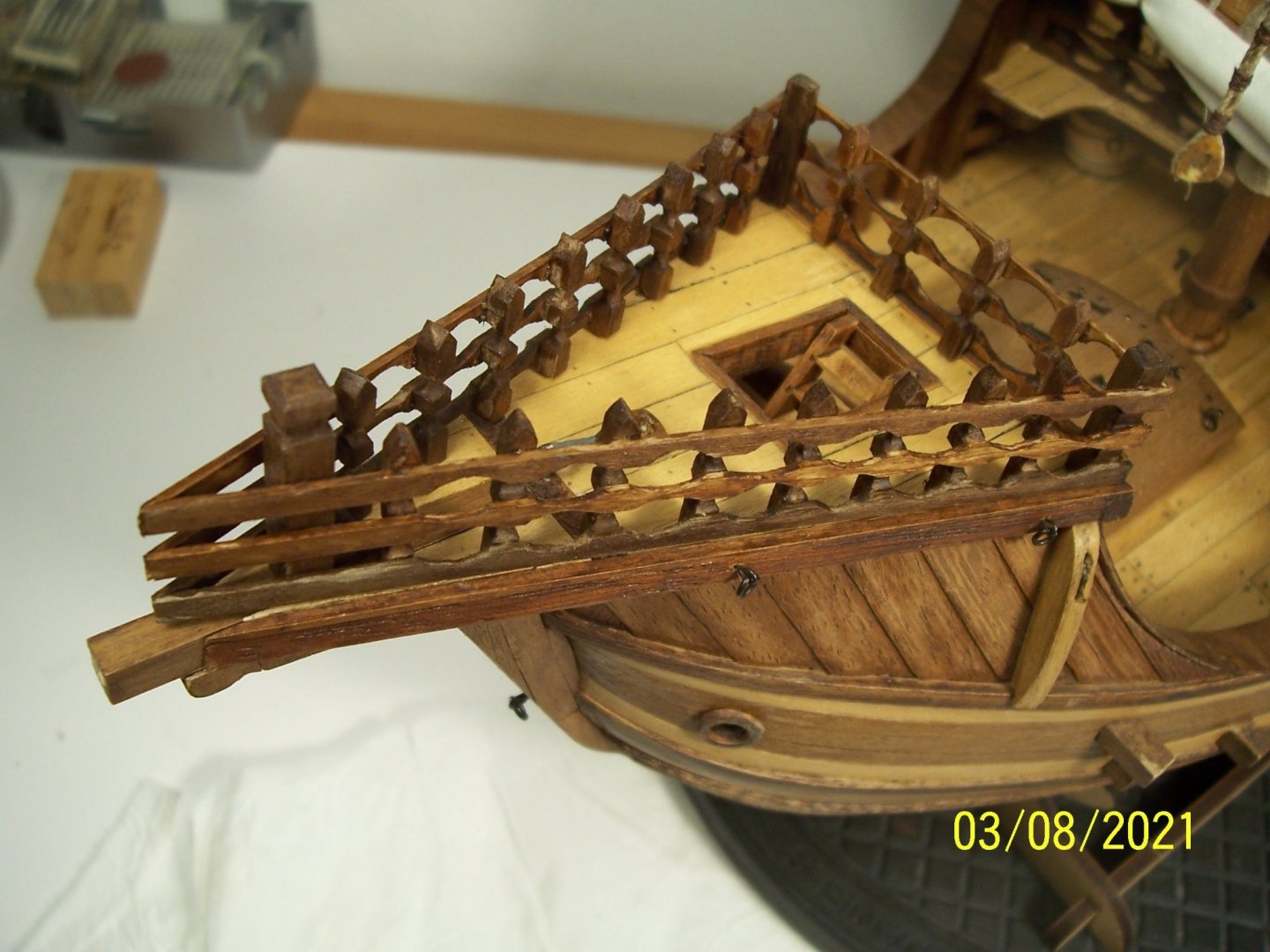
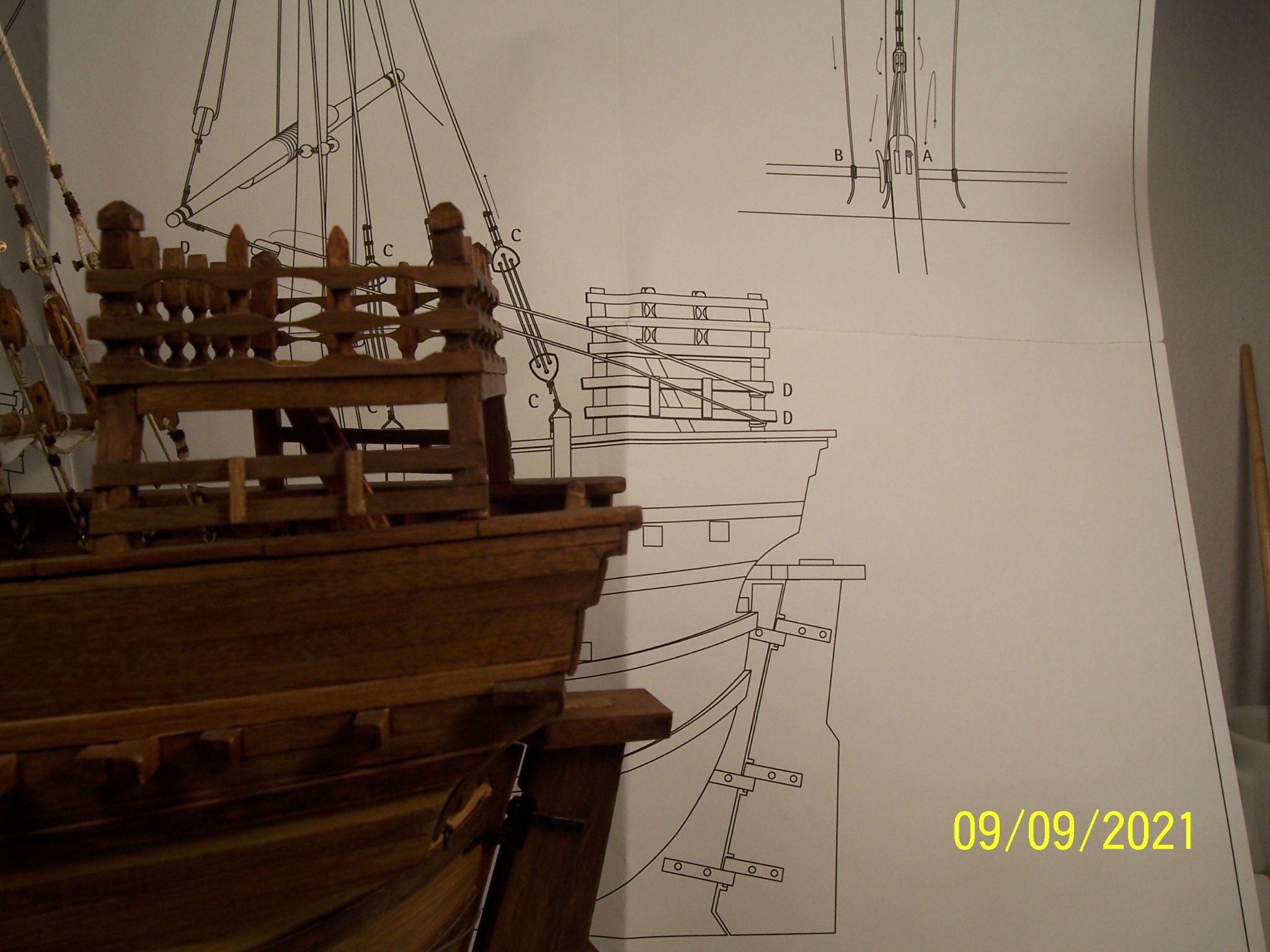
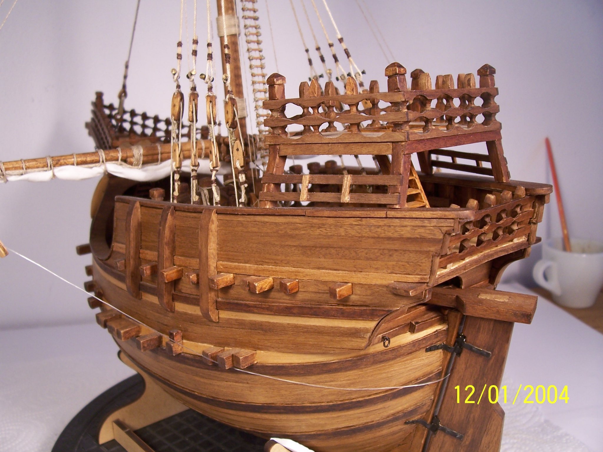
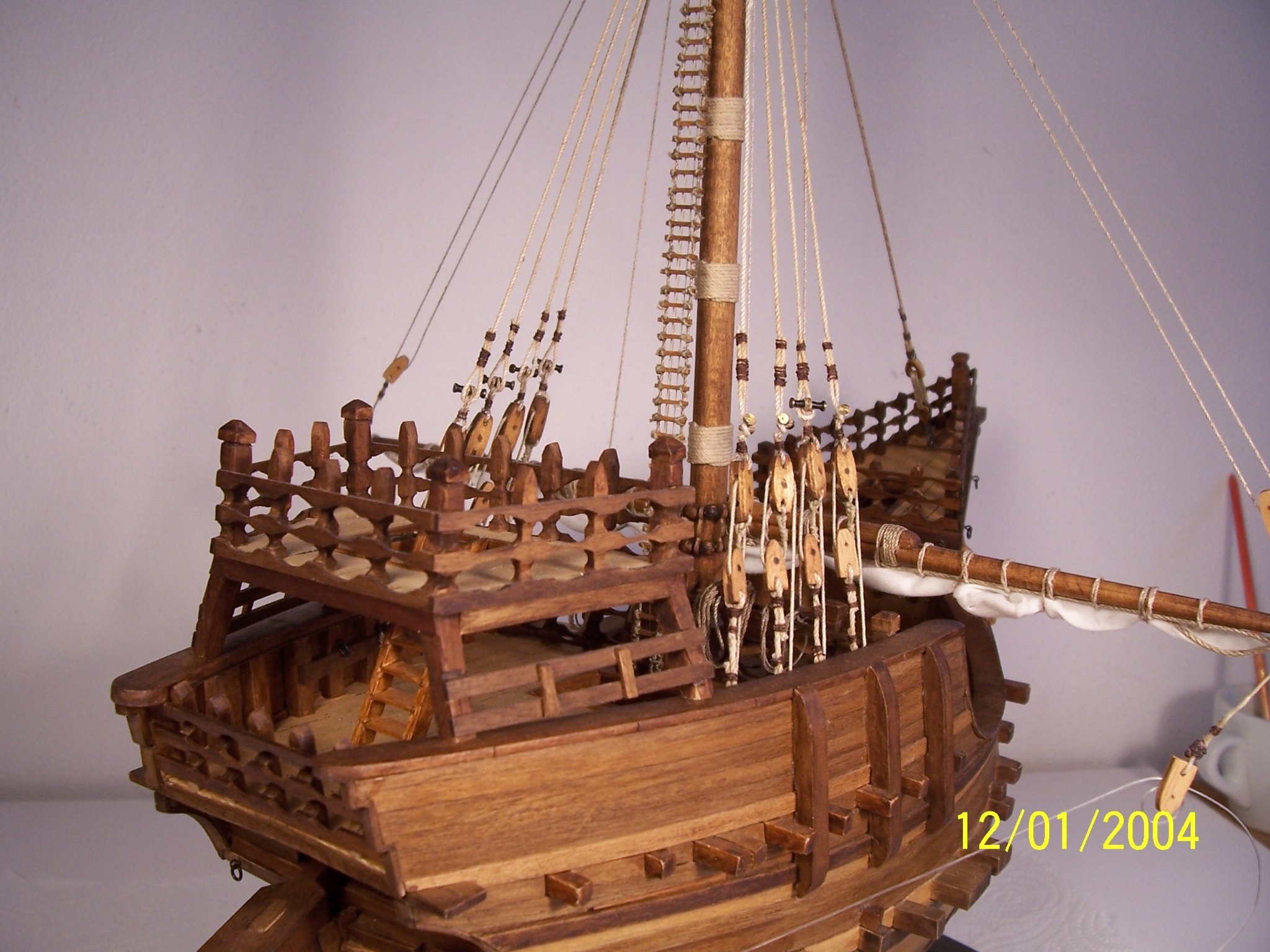
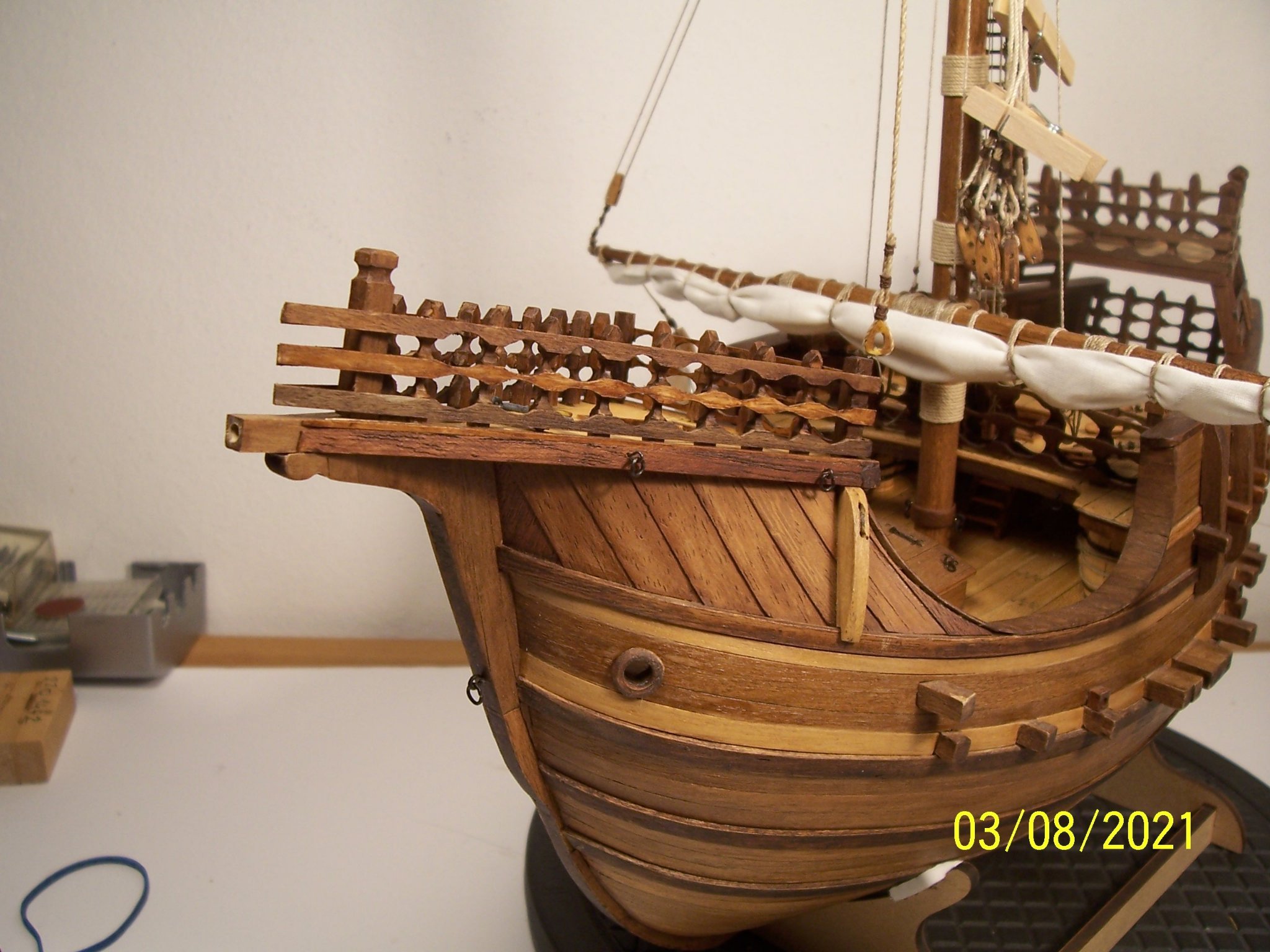
A warm greeting to the friends of the forum; I am very grateful for the attention you give to this model. The bow handrails of the AMATI project are very simple and linear; on the opposite the Nao of Matarò has them much more complex: An attempt will be made to reproduce the effect of the Spanish model. First of all it is necessary to cut to size and shape the supports; the corner ones are 4x4 or 5x5 mm and the others 3x3. Then select the ones that look the most like each other and glue them to the battens. After that, we glue the three sections together, after shaping the ones that end in a point at the bow extremity. Shape the laths with a round and half round file: Varnish with walnut impregnation, let it dry and finally glue the rails to the fore deck: The next works will be the laying of the main stay and the positioning of the shrouds. See you later and have a wonderful Sunday! Rodolfo
.JPG.256457eb0f014fd9e97d4796f64cea9b.JPG)
.jpg.df95e8df3b32e59059065c9c31748008.jpg)
.thumb.JPG.7724a2f30ced1cd4aa34762fb5d0d255.JPG)
.thumb.JPG.167b5b8267d61e767f77a8dab24dbd76.JPG)
.thumb.JPG.19476b2a5bf8847975e94b53bdcaa90c.JPG)
.thumb.JPG.796af0660a9506fa92cf1abb521dd50a.JPG)

.thumb.JPG.fa7cb274e9591ab6371a640b5276fc03.JPG)
-
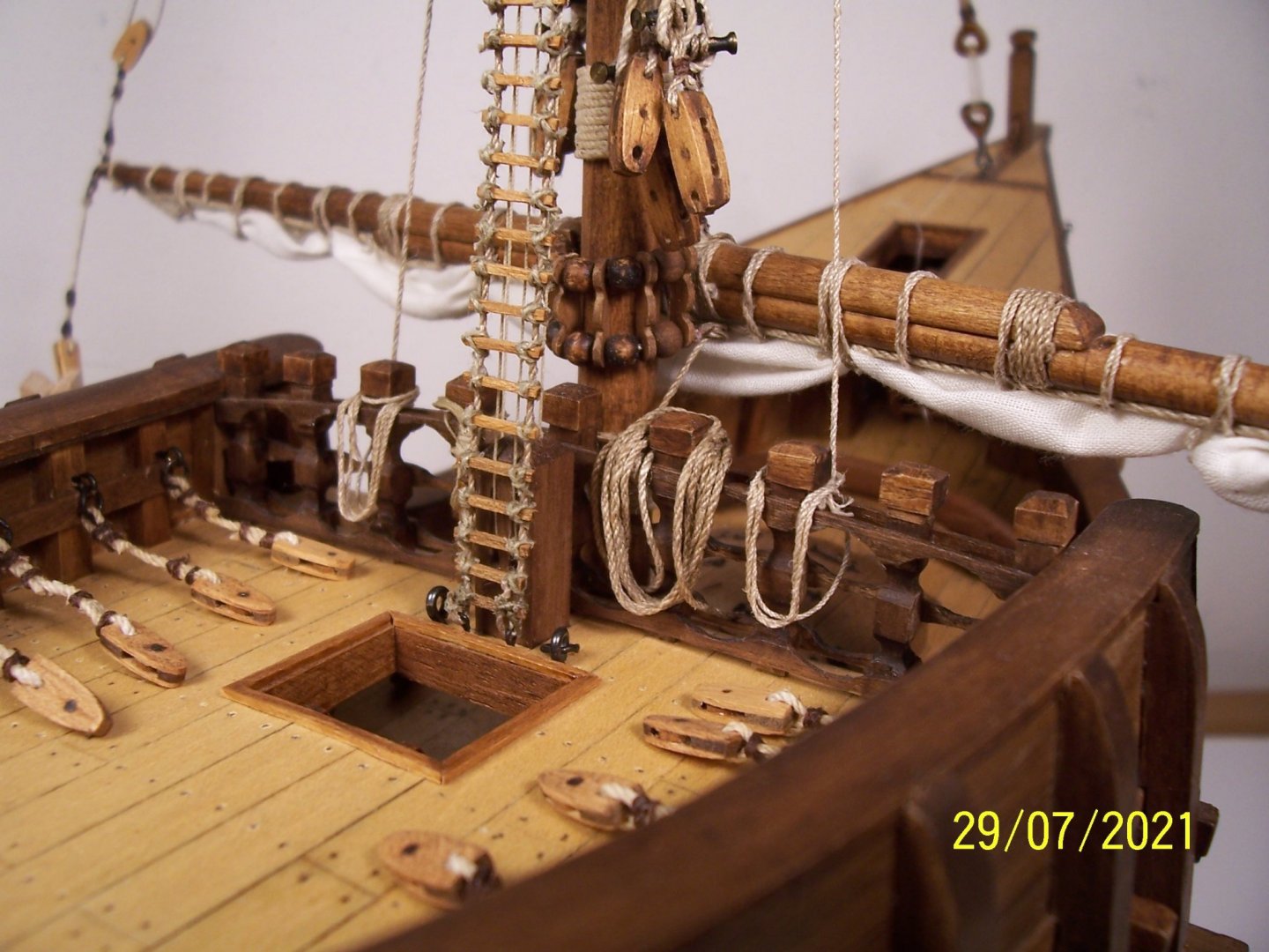
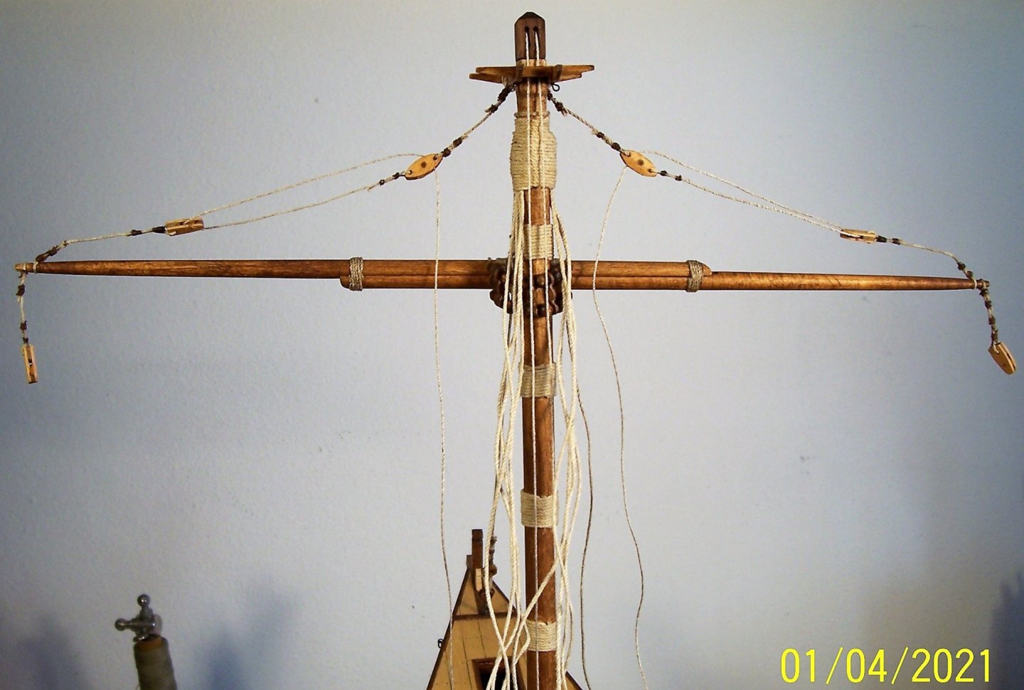
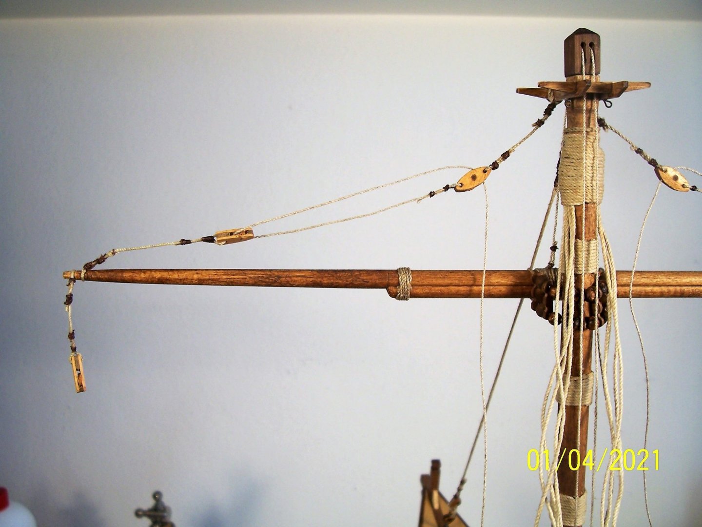
Warm Greetings to all friends of the forum! Finally starting to get the first rigging in place: the main mast lifts. The ropes have been tensioned and then smeared with diluted vinyl glue using a brush. The next step will be the three rails at bow, which look quite laborious. Good work everyone! Rodolfo
.thumb.JPG.41ea50ed2c7688f6f8b36be807183d2f.JPG)
.thumb.JPG.c834c77a9ad9e884d3812f2e4470392c.JPG)
.thumb.JPG.255e828b519279f3cb4f536519e102c7.JPG)

-
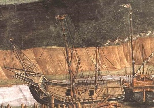
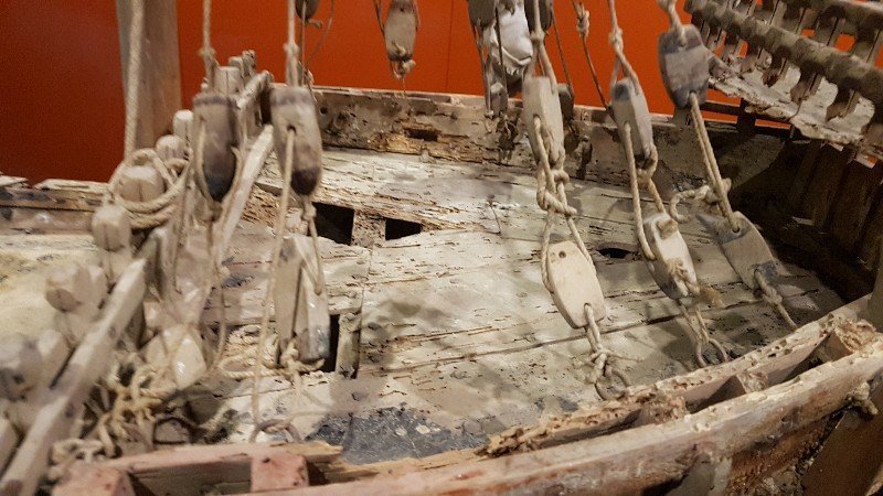
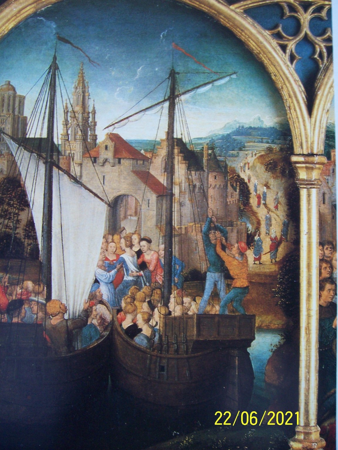
Dear modeler friends, at this point it is useful to think about how to put the catheads. The Nao of Mataro has a couple well detailed (and the accuracy of the work makes me think that the builder was skilled): As we can see, the problem arises that Nao of Matarò has one cathead in a more advanced position and the other more backward. The doubt is if it had four catheads and two were lost or if someone made a wrong repair (not very likely, also because dimensions are different). Yet I haven't come across any drawings or paintings with four (there are few even with two...among them a Botticelli's painting ). Someone has built a ship with four catheads: but, in conclusion, I thought that for such a small ship, one cathead per side was adequate. I preferred a simple solution, shaping with file and sandpaper slightly curved strips of walnut 6x6 mm. The pulley is only outlined by carving the wood a bit between the holes. To glue the catheads, it is necessary to lightly sand the clinker area, and this is the result after painting with oak color impregnating agent: See you soon! Rodolfo
.jpg.9e222259f1d7fd47691b64fe99ec5b82.jpg)
.jpg.eb0ca7442aec5db92c47e52c912c746b.jpg)
.jpg.0536ccd22e8ad210946c55cd81d955e1.jpg)

.thumb.JPG.93e8faee693b66b10b13555e9facfda0.JPG)
.thumb.JPG.8392ab541721ea96d4922739fa71ee3e.JPG)
-
Thanks Steven, unfortunately I've forgotten to give a bit of color to the sail; maybe a drop of gray...but now it's too late.
-
Greetings to everyone! After the first attempt, I then made two more. In the last one, I drilled the holes through the fabric with a glowing needle and, in my opinion, the result is much better as the burn around the hole simulates stitching. Here is the result of the third attempt; unfortunately I did not take pictures of the sail before putting it on the yard. Next step will be: the cathead. See you soon! Rodolfo
.thumb.JPG.47a6f266b460ab4aa517c6bca0856e54.JPG)
.thumb.JPG.f9be4370c9154ef0c16056eb86550688.JPG)
.thumb.JPG.c4e0efc864caa18b3ac34aaf13737d5d.JPG)
.thumb.JPG.fbecb8c8ccaaf3518ca90d142151a7fa.JPG)
-
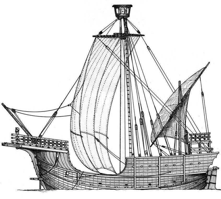
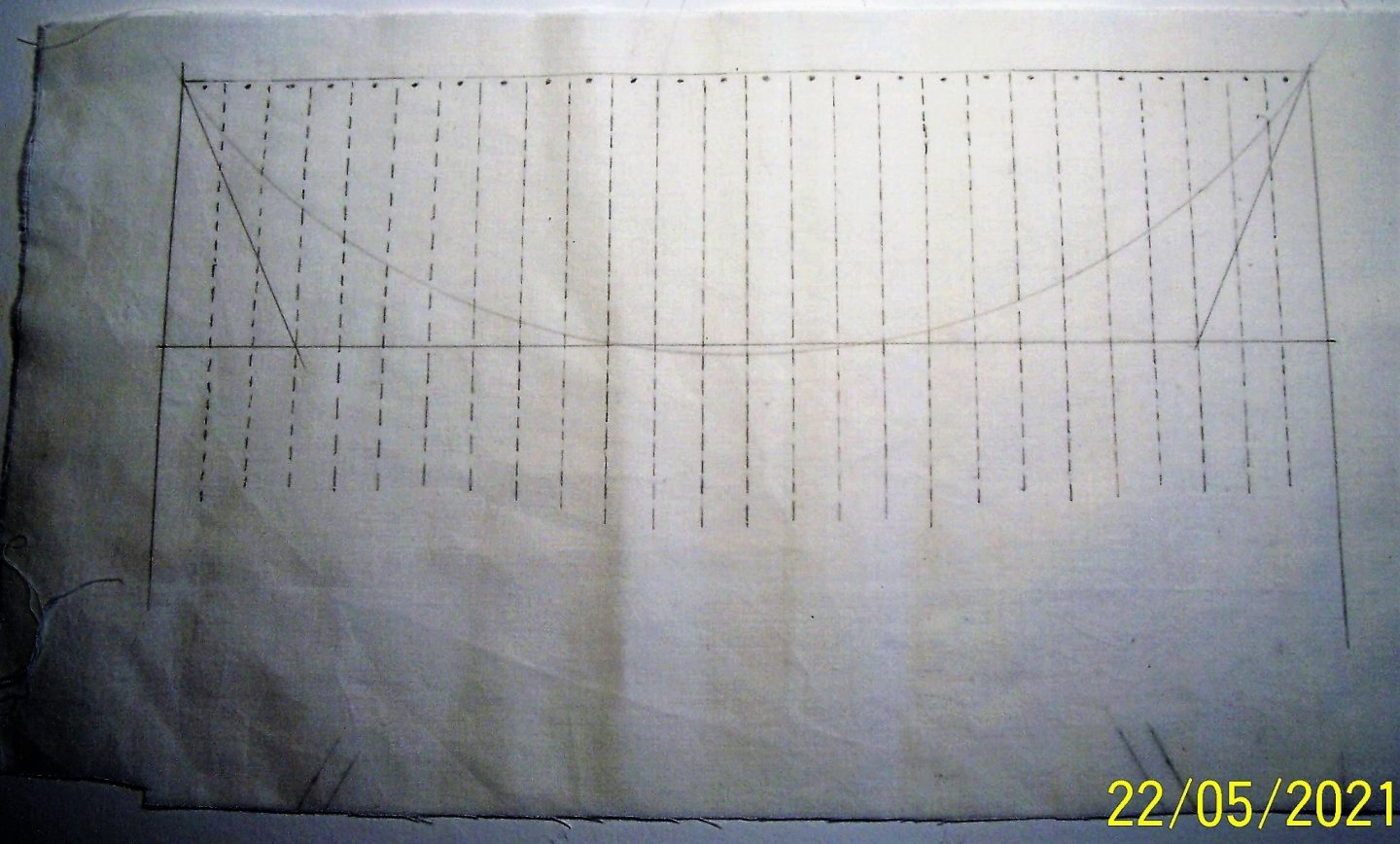
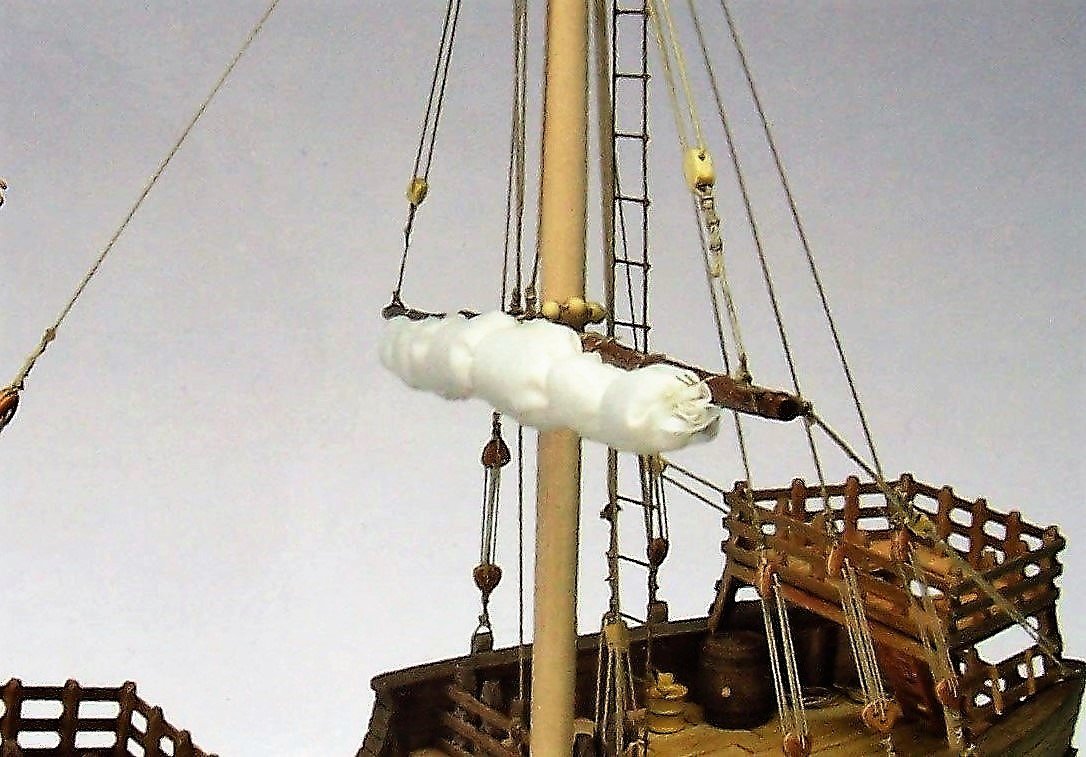
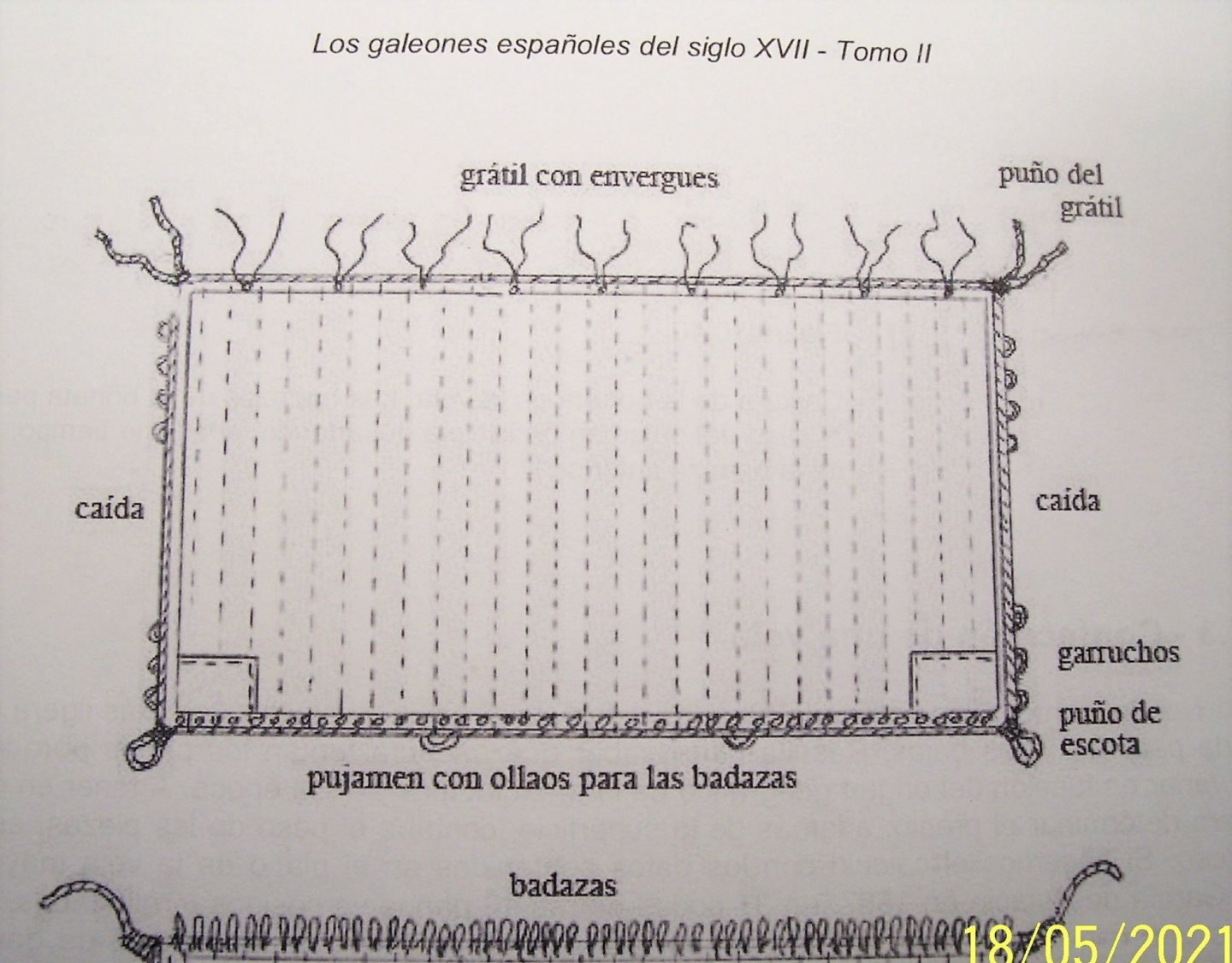
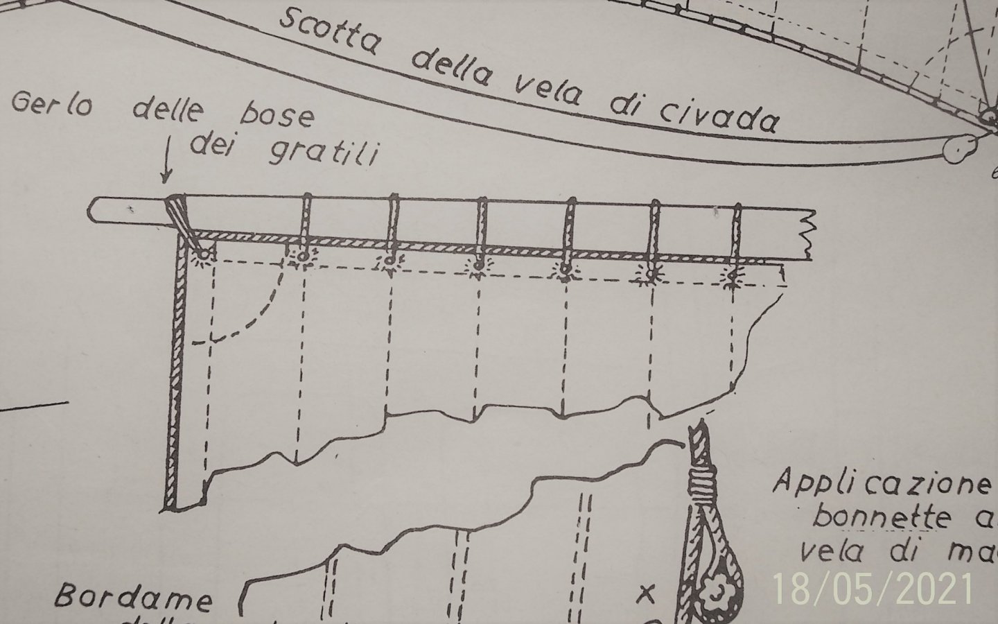
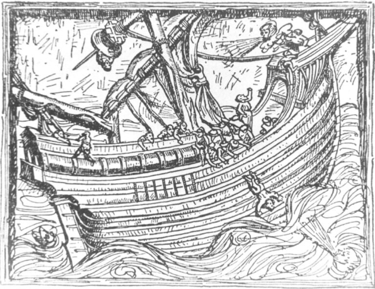
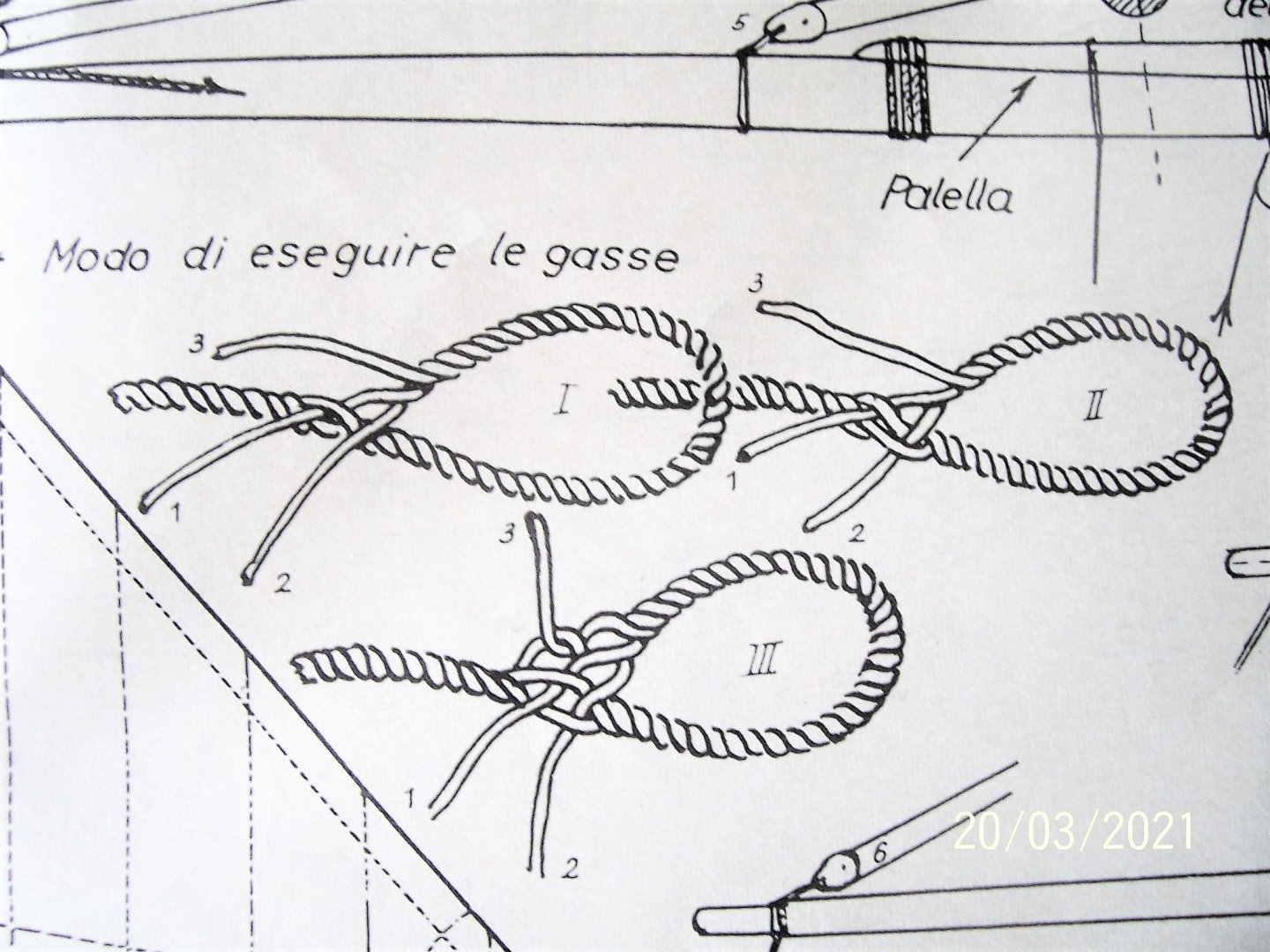
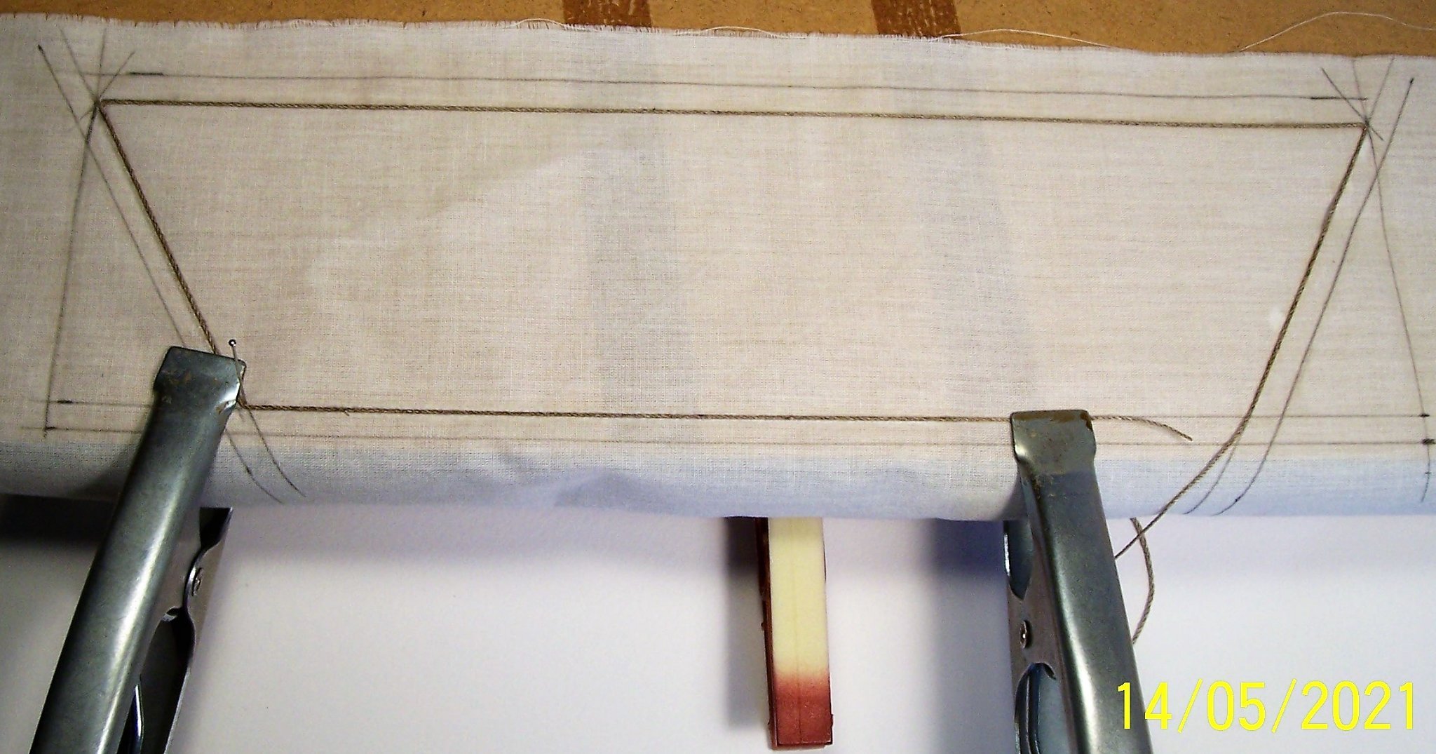
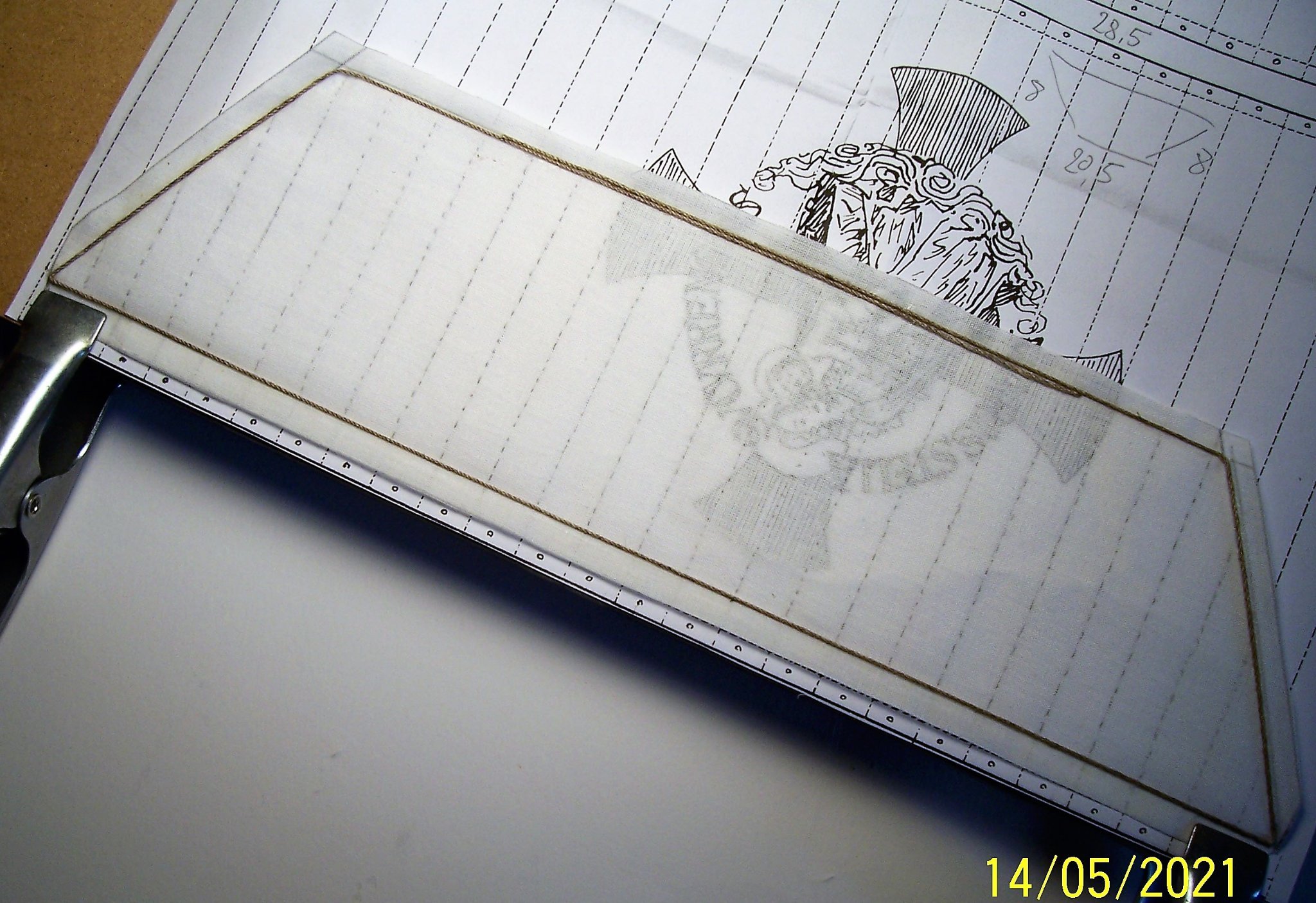
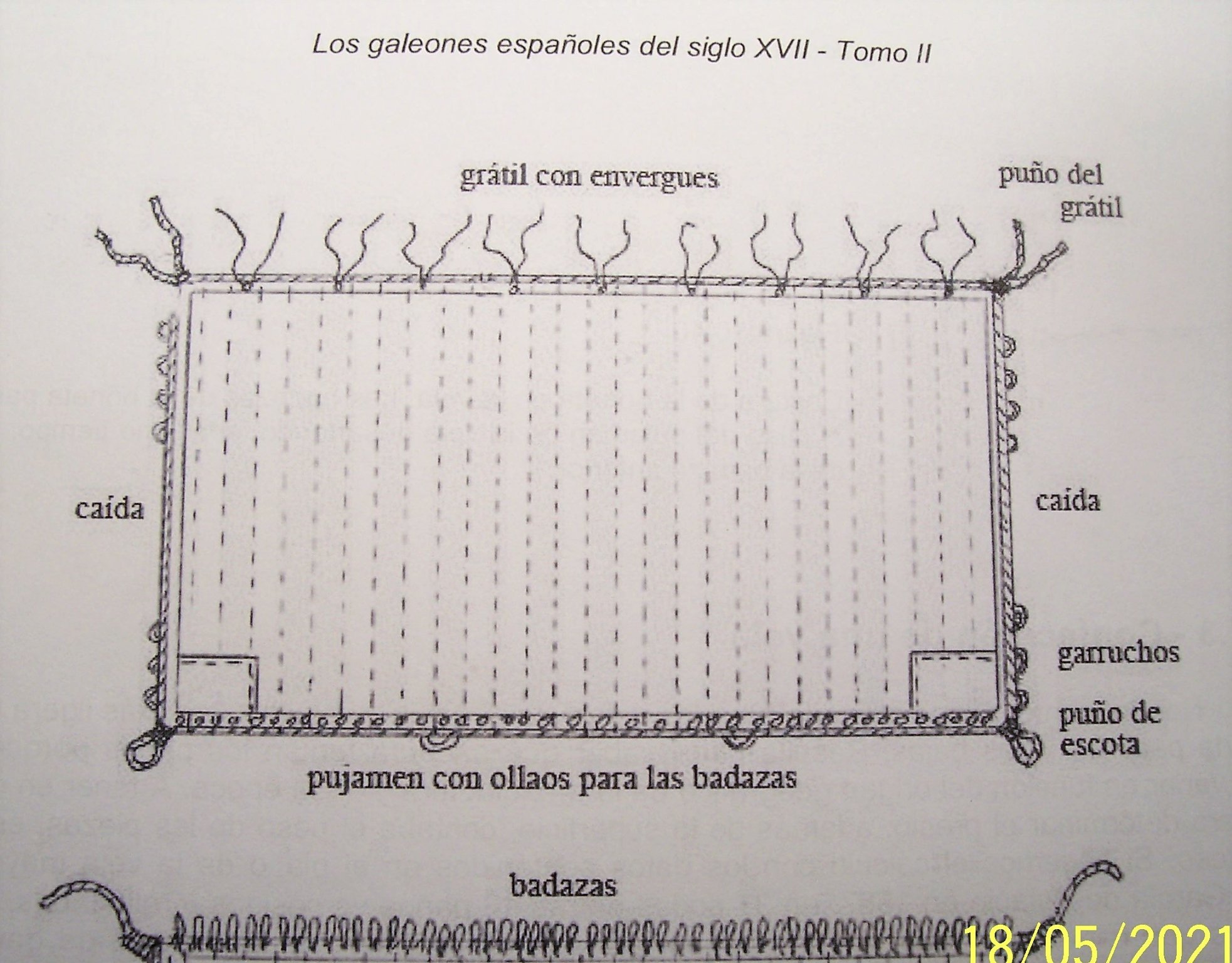
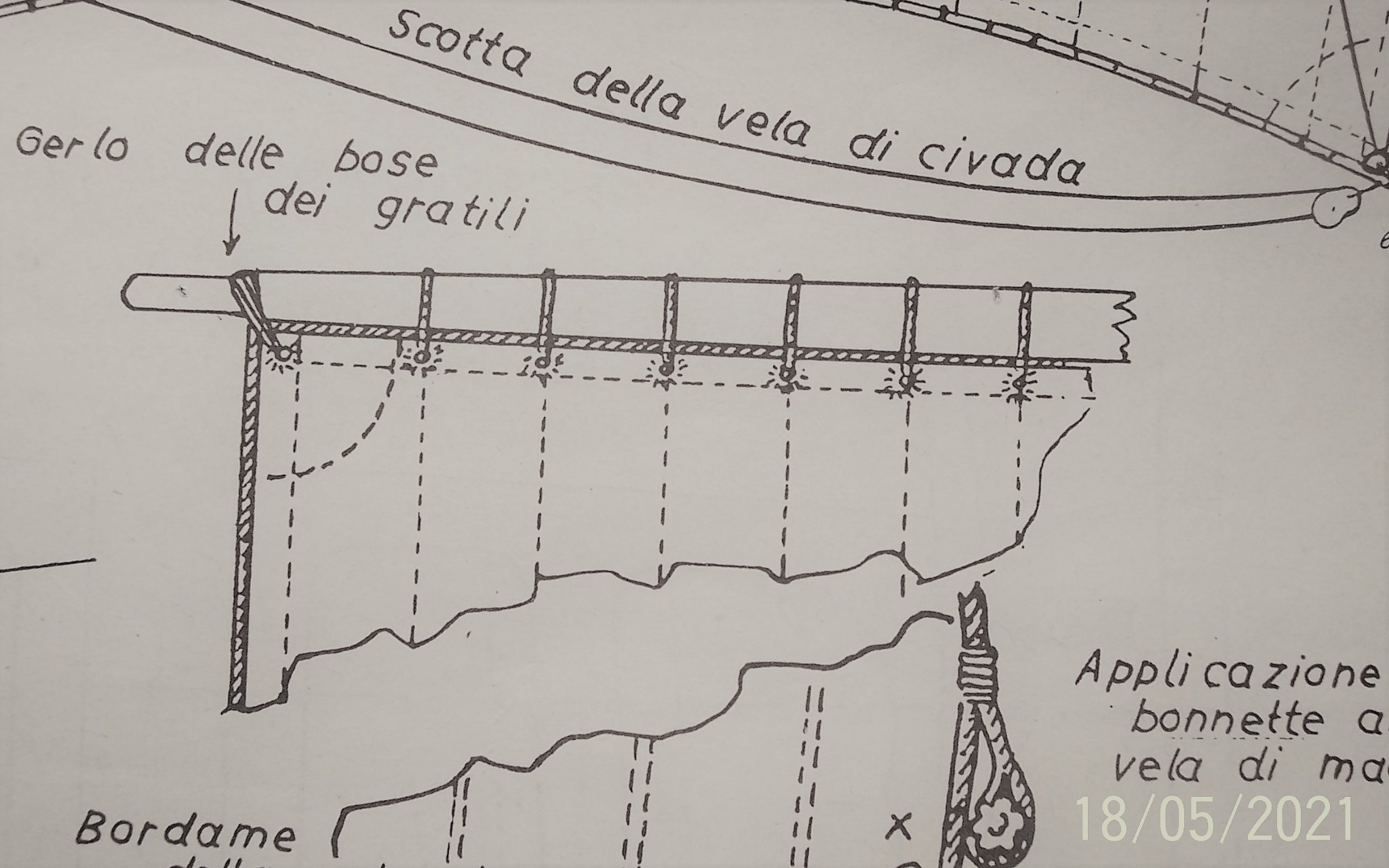
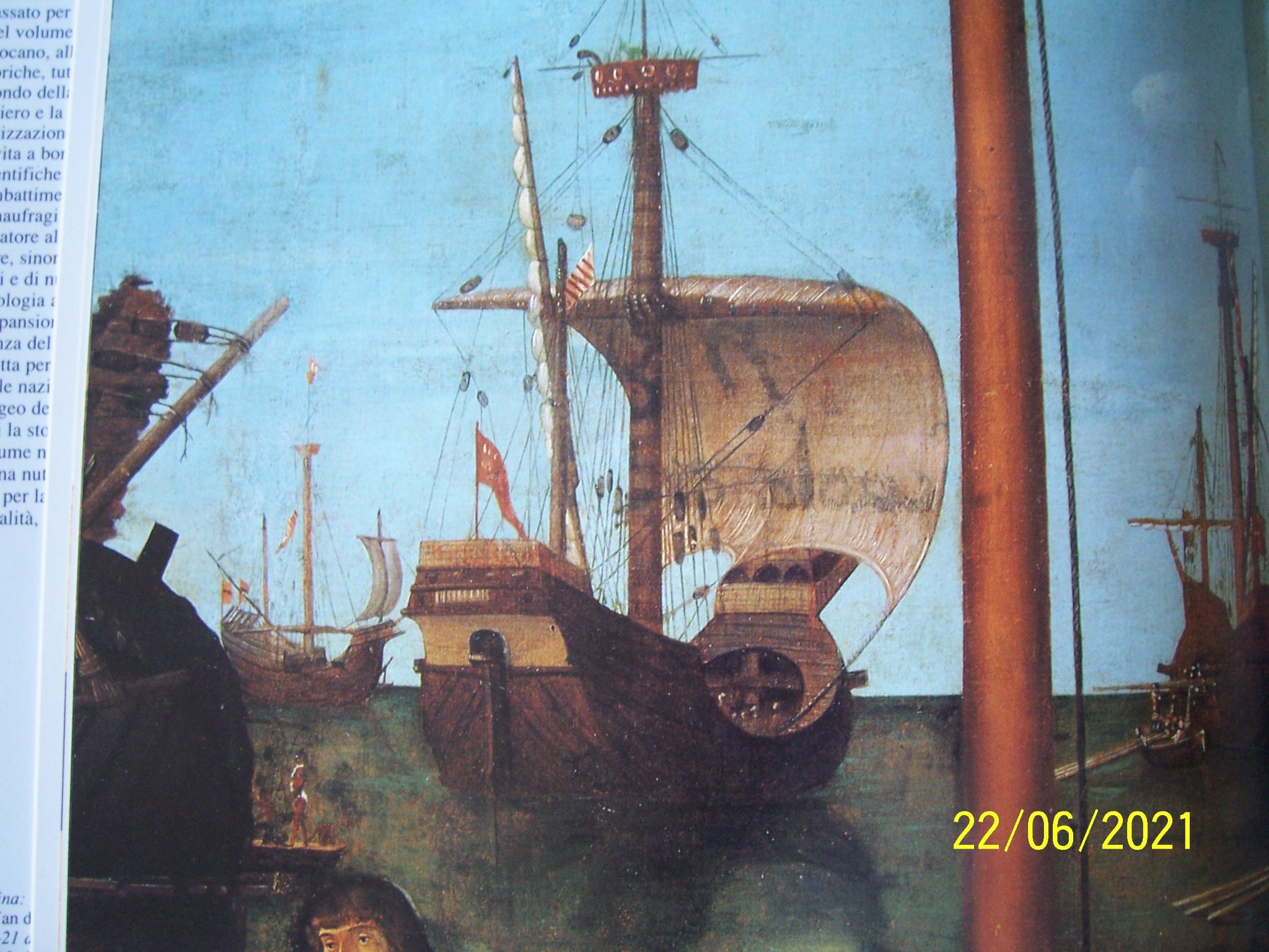
Dear Friends, AMATI puts the picture of the ship with the sail only on the cover of the box: it is a kind of sausage with six laces that bind it to the yard. The technical drawing does not report anything about the shape and size of the sail, so we have to arrange: Pictures from the period show that the sails wrapped around the yards show a very slim shape: Obviously, the wrapped sail model cannot be reproduced in perfect scale because it is too thick compared to the original. Different would be the case for the unfurled sail. For that reason I cut the fabric in a reduced way compared to the theoretical sail (I took as reference the mainsail of the Santa Maria of Adametz' drawings in proportion to the yard of the Cocca). The shape will be an "inverse" trapezium: The sail cloths are simulated on the back of the sail with a pencil. I glued a 0.5 mm wire along the inside perimeter, cut out the sail leaving a side margin along the perimeter, and then folded the outside overhang gluing it and embedding the inner string. Next, I glued another cord (the luff cord) of about 0.8 mm diameter to the outside, with rings at the lower corners. This is the result of the first attempt (The holes were bored with the tool in the photo): As for the way to mount the sail on the yard, I chose what is described in: "Los galeones españoles del siglo XVII - Tomo II" authors Cayetano Hormaechea, Isidro Rivera and Manuel Derqui, Ediz. "Associació d'Amics del Museu Marítim de Barcelona" with the addition of a drawing by H.E. Adametz (for his Santa Maria): In retrospect, though, I think it's better to put a loop of rope at each corner: it saves the trouble of tying the sail to the ends of the yardarm. Moreover, the work will be easier if the blocks will be fixed after the sail. See you soon! Rodolfo


.thumb.JPG.a6441de93502fa95d3ef694ddf6455b1.JPG)
.thumb.JPG.f268ca9dd3293433c5071b675c96971b.JPG)
-
Dear friends, The work continued trying to fix the blocks in a uniform way, but it is not very easy. Pictures of the time show both blocks fixed close to the bulwark and far away; runners can be short or long as well. So there is a lot of freedom of action: As a first step, I shaped a steel wire to keep the distance constant. Then I tied the block to the rigging removing the excess rope at the end. At the end, a runner of clear elastic wire temporarily joined the upper and lower blocks so I could get an overview. If I could go back, I would tie the blocks to the deck via rings attached directly to it or to a rafter; but it's done now. In any case it is an improvement over the three shrouds proposed by AMATI. After that I will cut away the elastic thread, remove the blocks with the toggles and lower the yard down to try to put the sail on. See you soon! Rodolfo


.thumb.JPG.9bac839d6e3243789373a0352961a2be.JPG)
.thumb.JPG.873cadb5fef5dae1fa7ad73854e9f4c1.JPG)
-
You're right Steven, wooden or metal toggles were still used on sailing boats in the Mediterranean Sea during the last century, as described in a beautiful Italian book "Vele italiane della costa occidentale" by Sergio Bellabarba and Edoardo Guerreri, as seen in this drawing: Rodolfo
.JPG.57357df595c41e039a171f85171d9086.JPG)
-
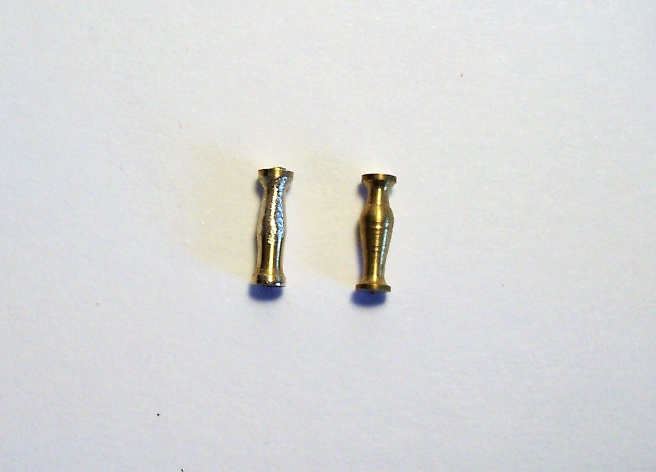
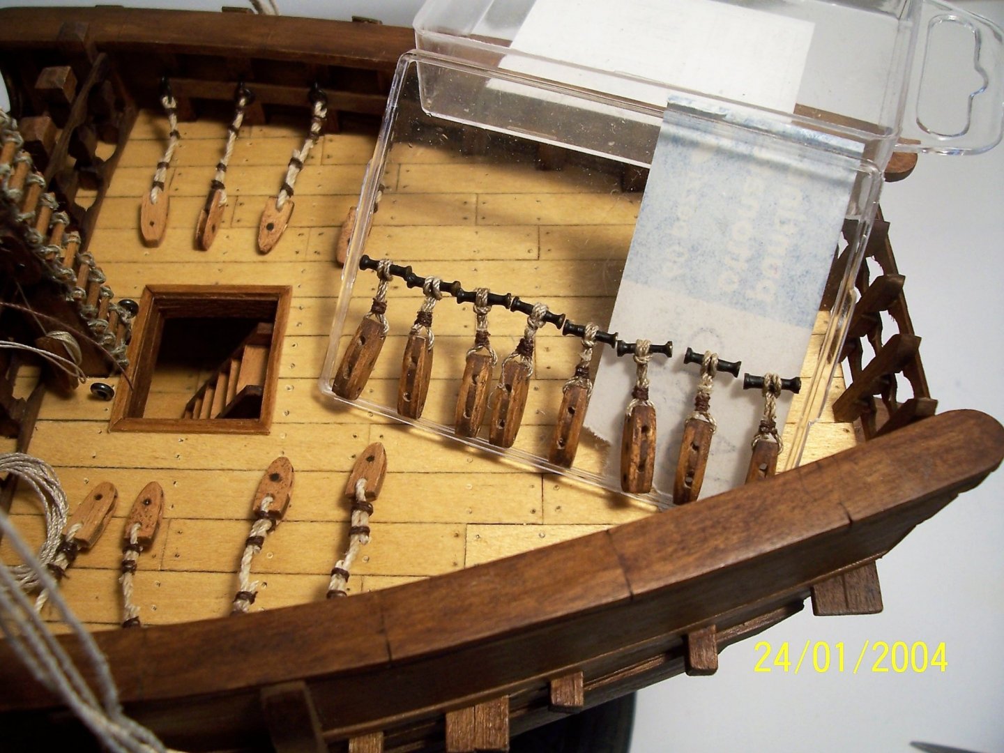
Dear friends, here we are! Having read that the taggle was made of metal, I then shaped some brass columns to try and fit them. Then I colored them black. I also used blocks with a single hole for those attached to the bulwark and two holes for those tied to the shrouds. I have made a simple tool to obtain ties of equal length for the upper blocks: Now all that's missing is the connection between them, trying to maintain a certain linearity and symmetry: See you later! Rodolfo


-
Congratulations! You've done a super work, even considering that repairing is more difficult than starting from the beginning.
- 740 replies
-
- 3
-

-
- Tudor
- restoration
- (and 4 more)
-
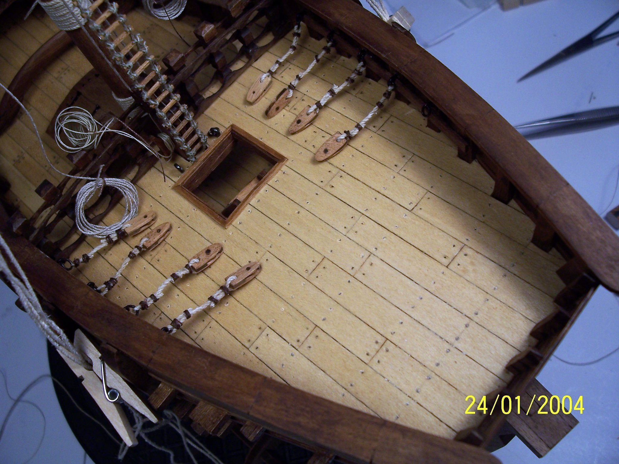
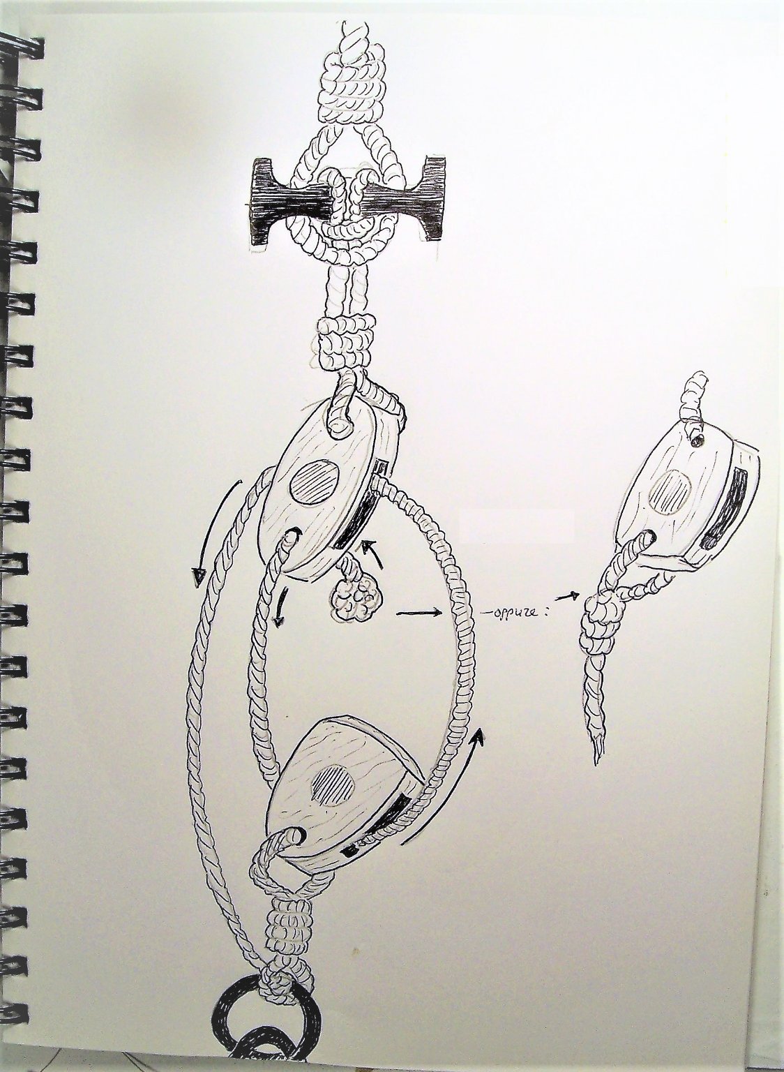
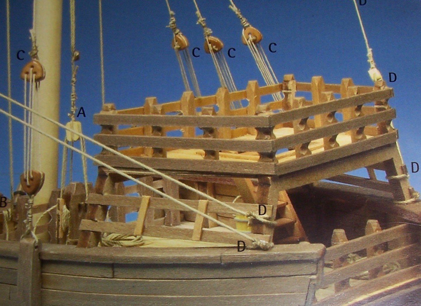
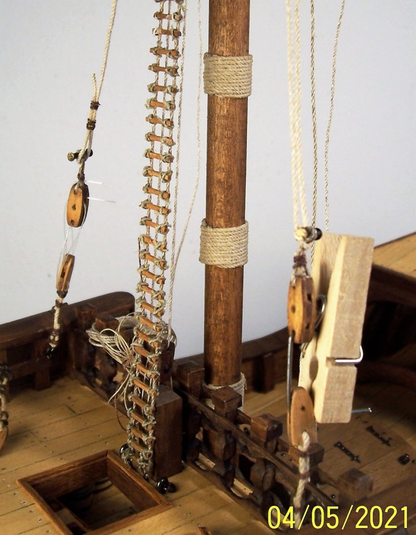
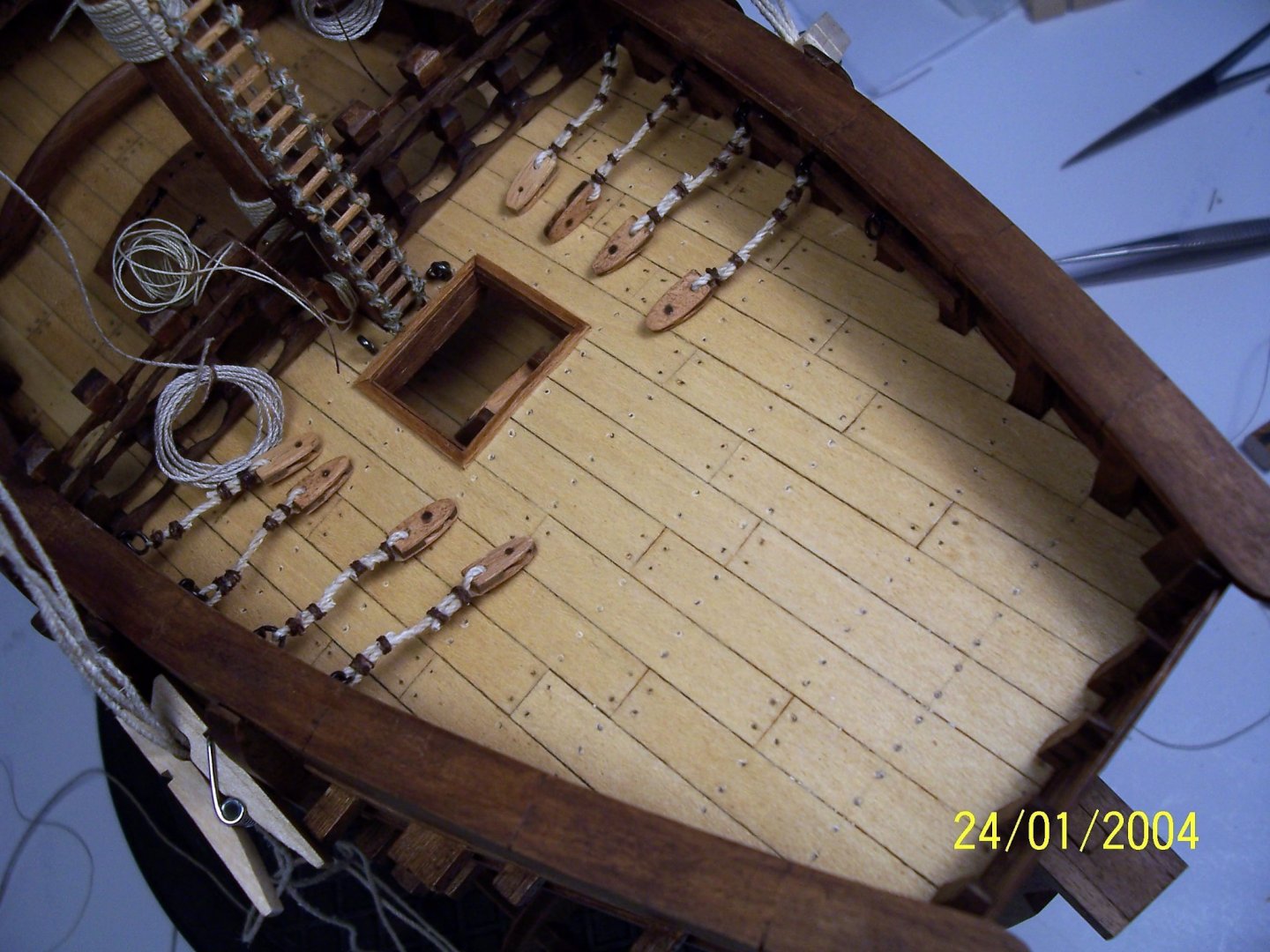
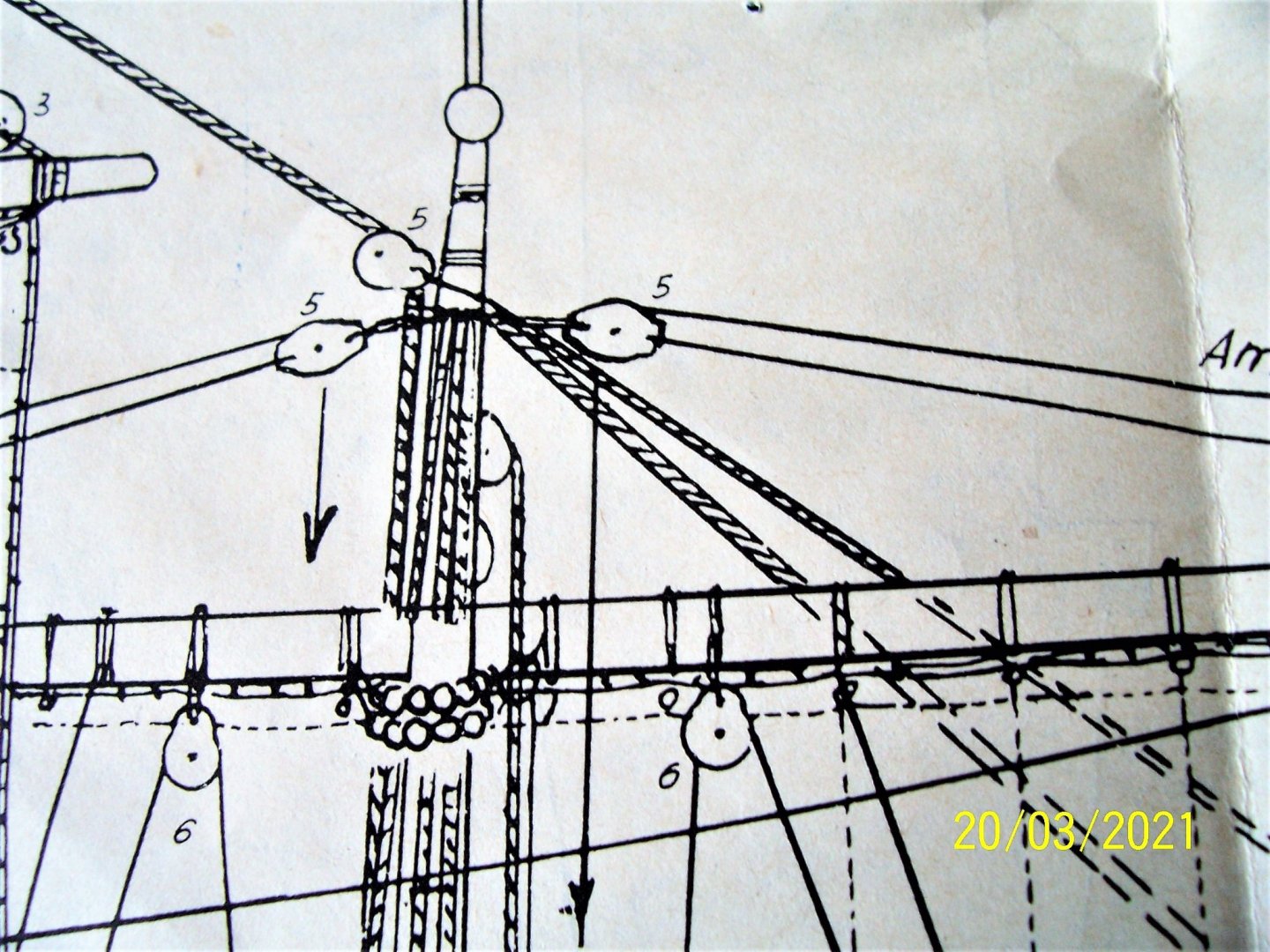
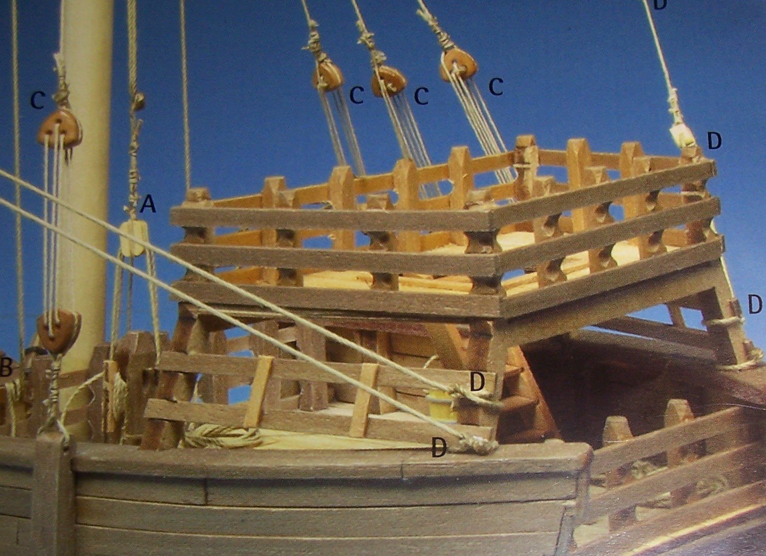
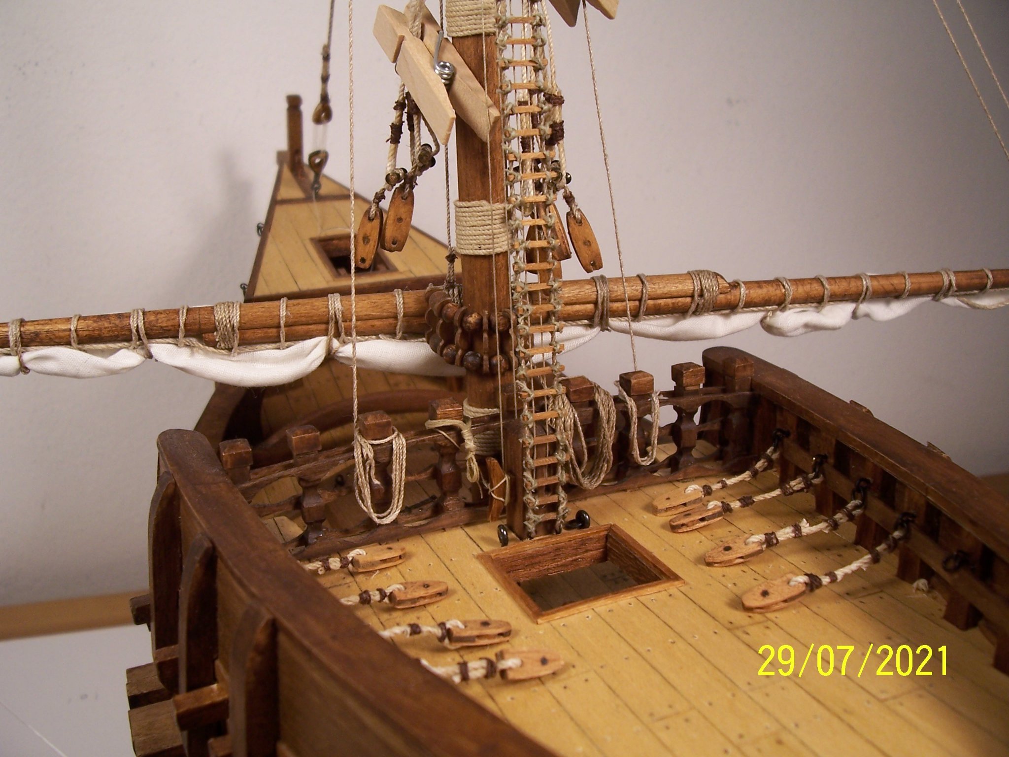
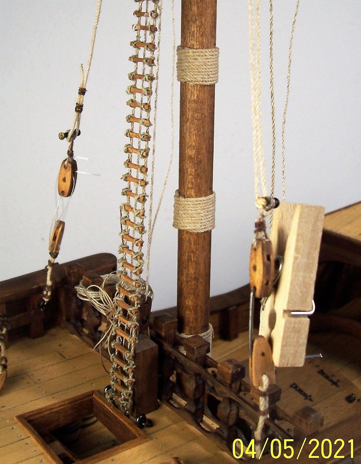
Dear friends, now we've to move on to laying down the shrouds. First of all, if I could start now, I would put some rings directly on the deck, close to the bulwark. Alternatively, I would put four/five rings on a beam fixed to the stanchions of the bulwark with metal bars to support the lower blocks. Instead, I attached the rings directly to the stanchions, copying the solution adopted in the Nao of Matarò: she also has their blocks tied to the rings with a rope: Then, lower blocks were attached to the rings with a rope. In order to maintain a constant distance between the blocks and the main rail, I used a screw compass: I put four shrouds on each side, but it is also possible to put more (but you have to think about it at the beginning; now it is late): Obviously the date is wrong! Regarding the connection between the blocks, after having seen many solutions, I was inspired by this one, described by the following drawing for elucidation: That sort of black colored "handlebar" is the taggle also said "borello or borrello" in Italian and can be made of wood or metal. I preferred to made them of metal. This will be the topic of the next post...see you soon! Rodolfo
.jpg.e63b76a1ebc3230b5829ea941dbf42c1.jpg)


-
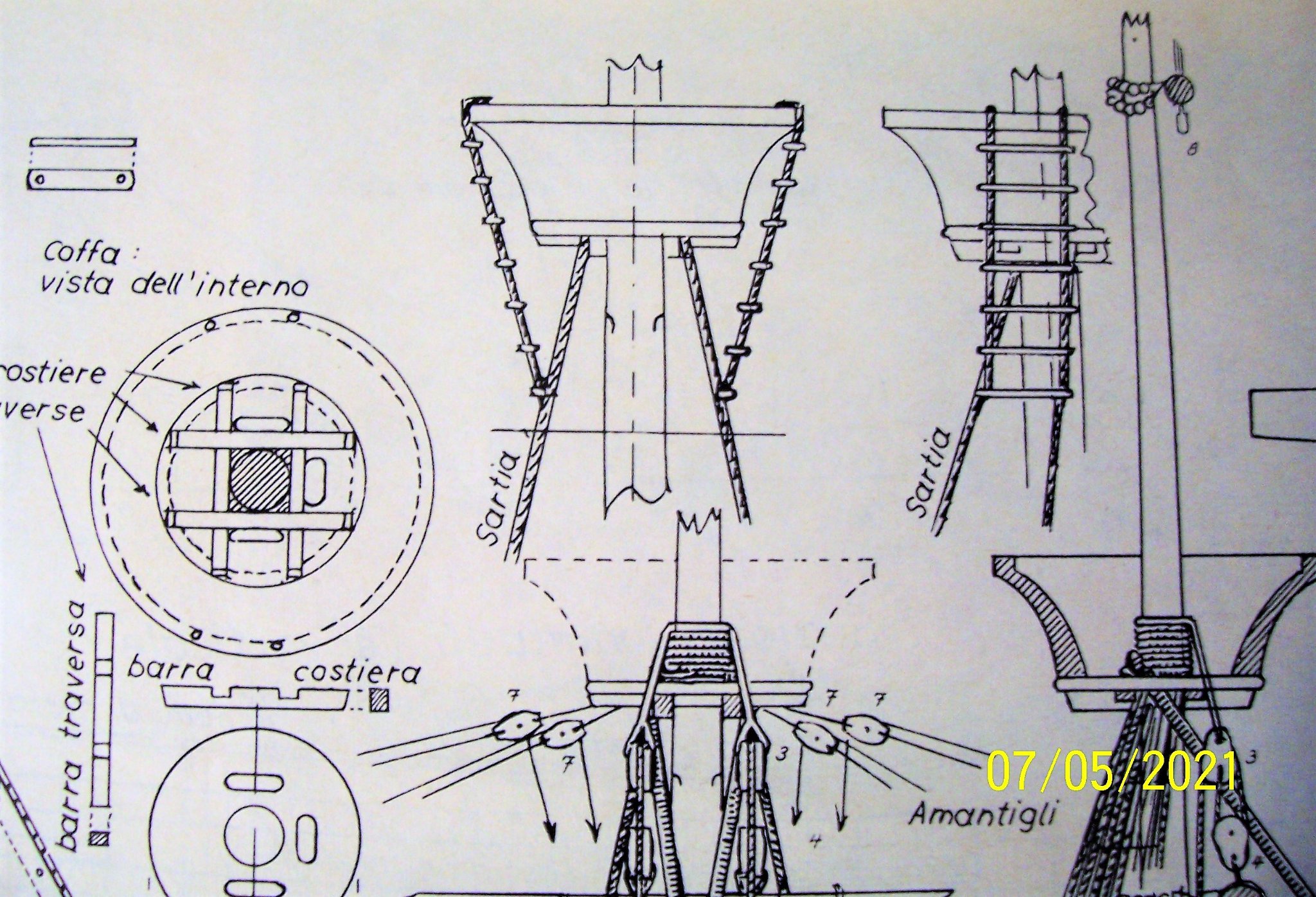
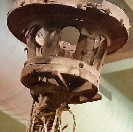
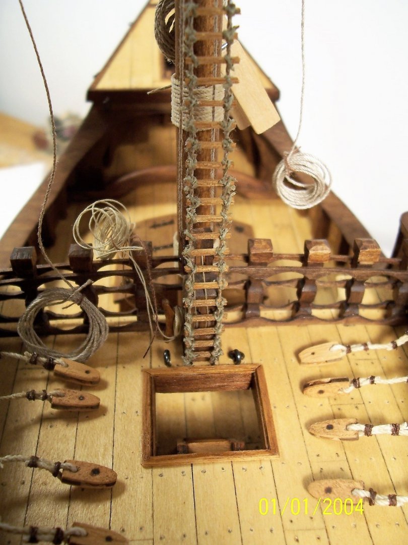
Dear ship-modeler friends, now it's time to build the ladder that leads from the deck to the top. AMATI instructions are not very clear: Documents of the time show that the top could be closed at the bottom: in others it could be opened, like in this one "Schlusselfelder Schiff" from 1503: In H.E. Adametz's drawings for his Santa Maria, the top was closed: but in our Nao it seems to be open or perhaps it has broken at the bottom over the centuries: After that, I've decided to build a Jakob's ladder ending in a hole in the bottom of the top. After three or four attempts, this is the least worst I've come up with: See you soon! Rodolfo
.JPG.e8a3bb2c199eb6a72792d2d2866d45e1.JPG)


-
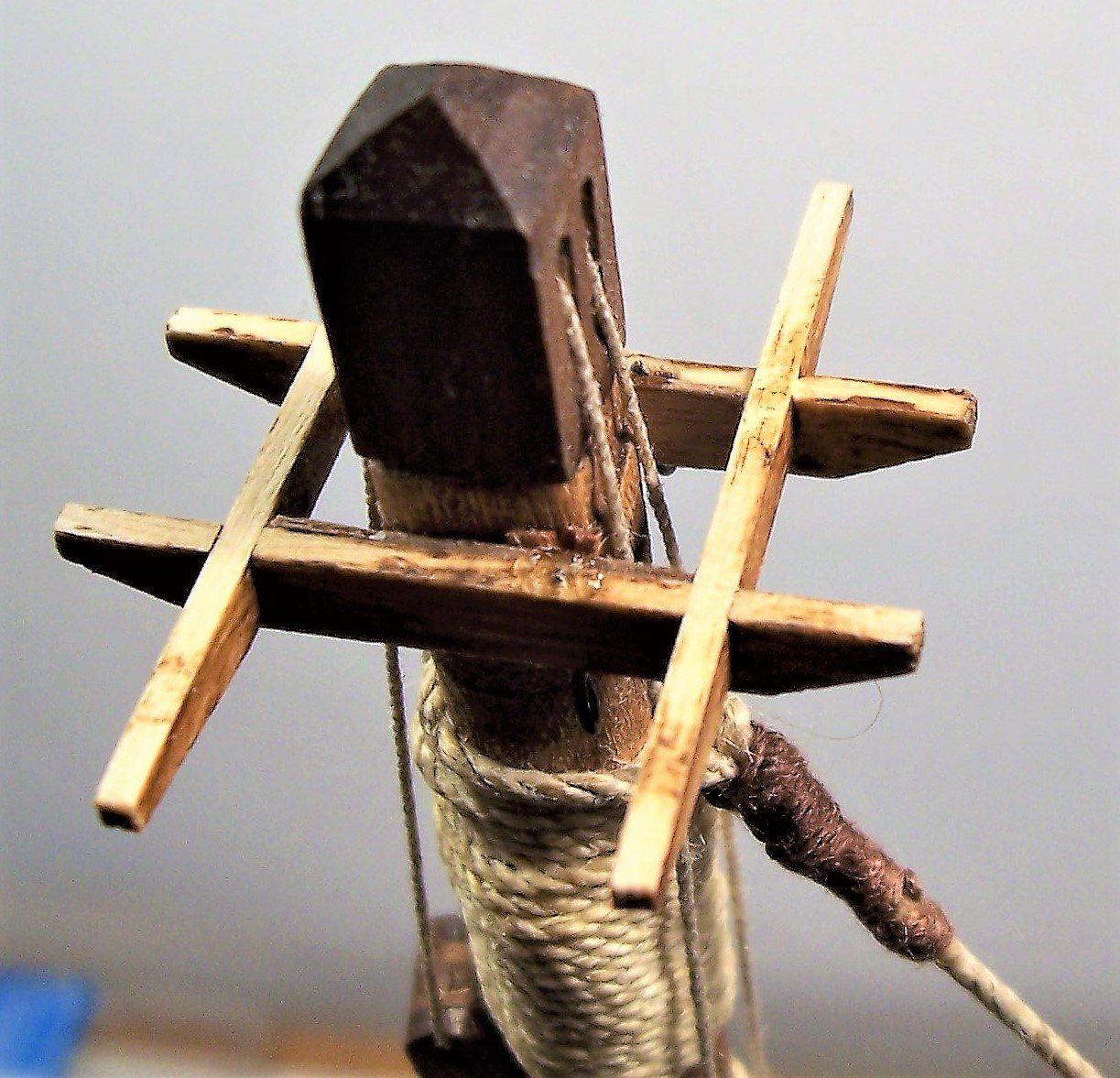
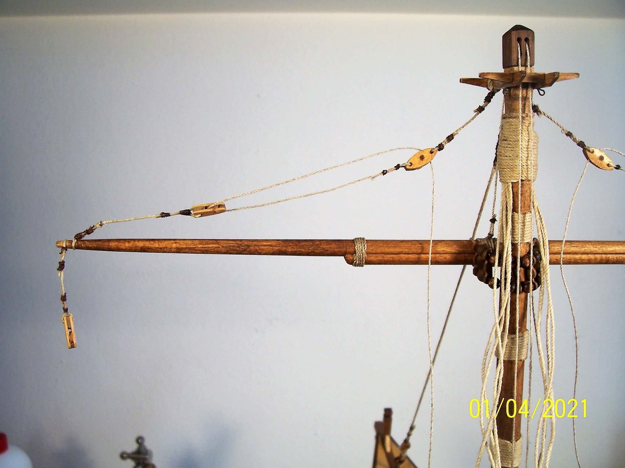
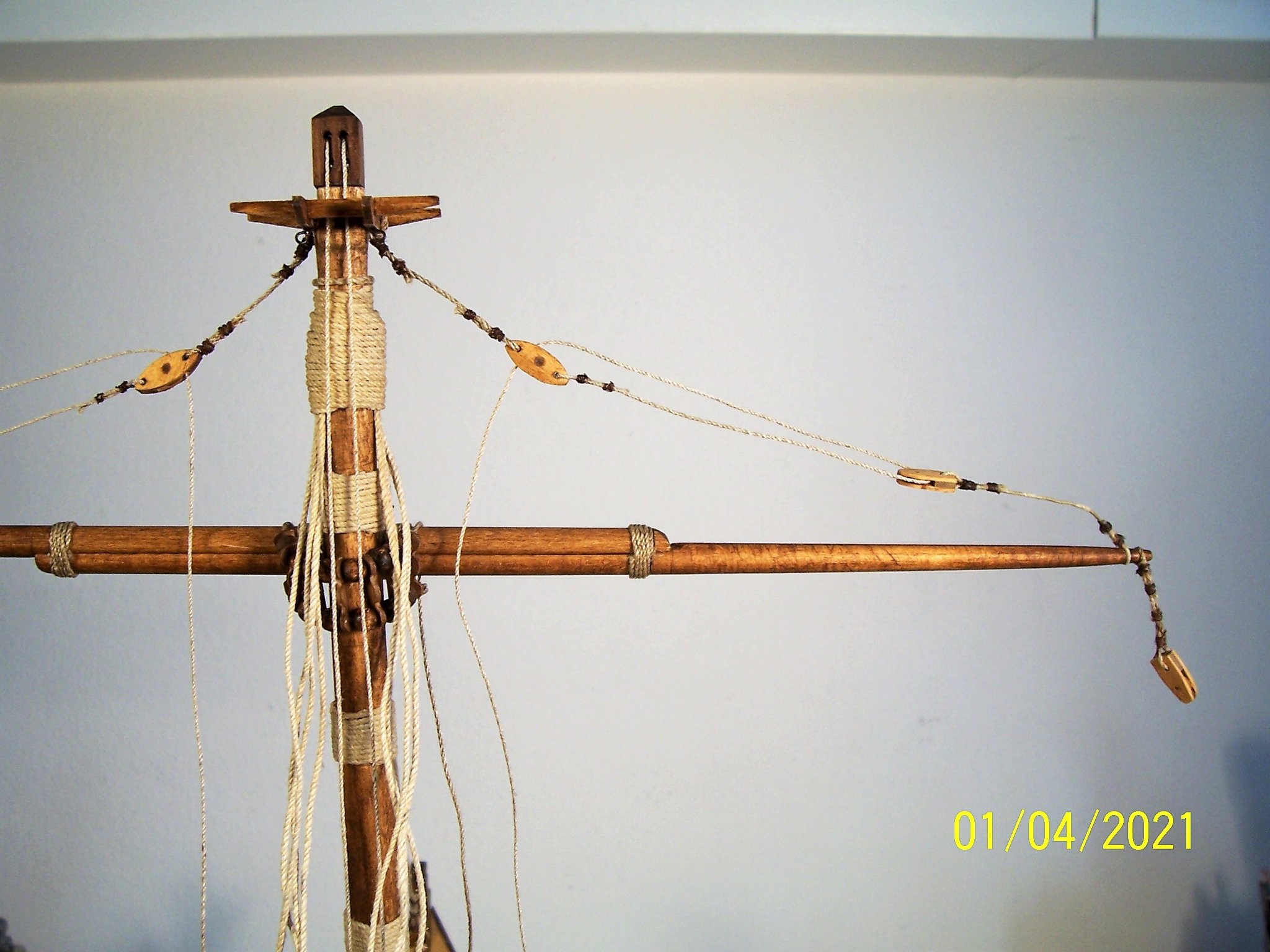
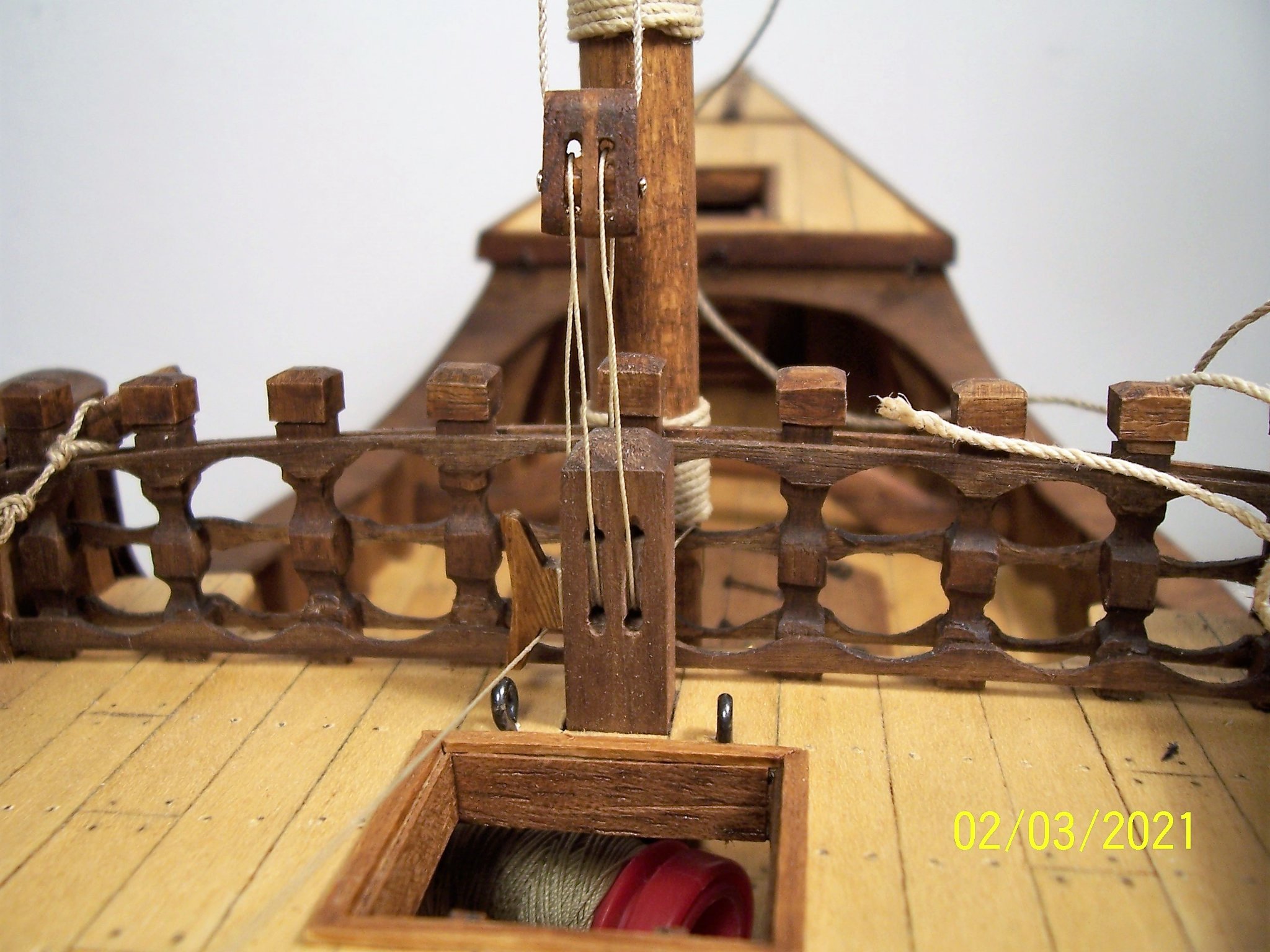
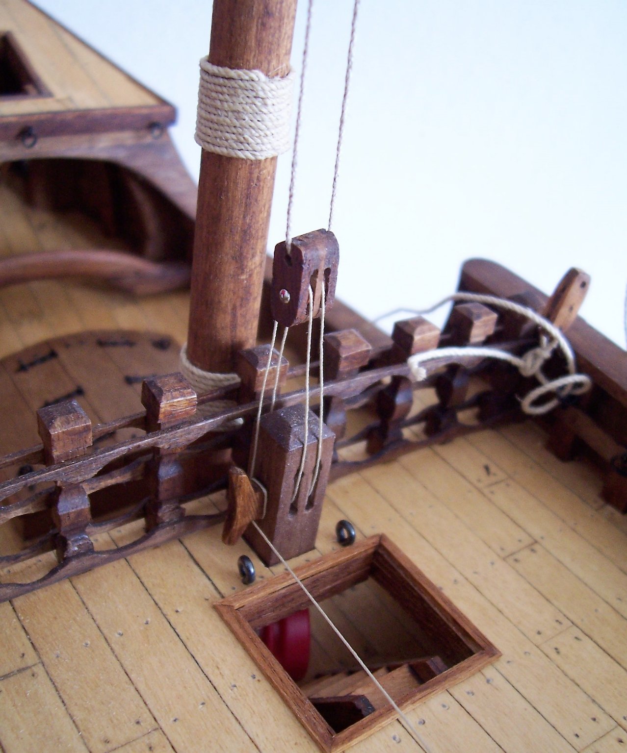
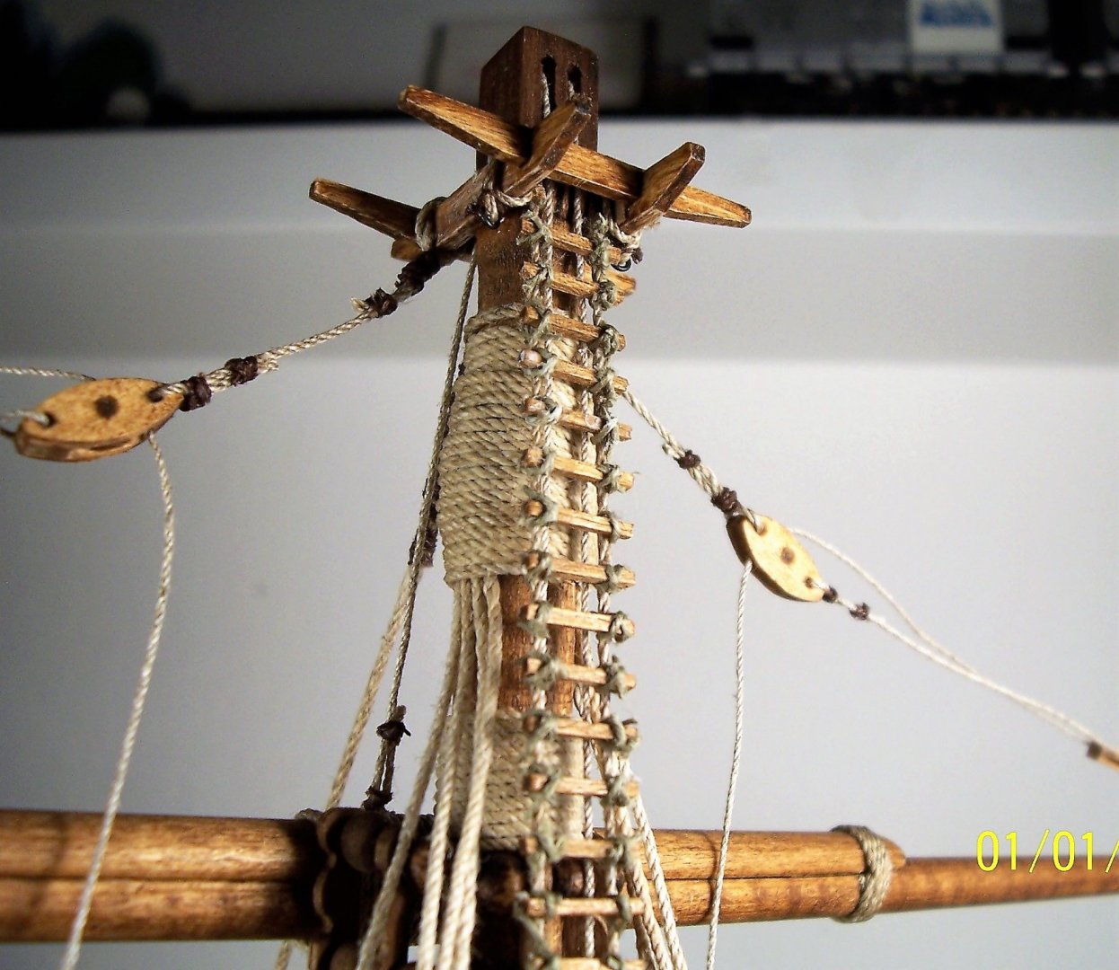
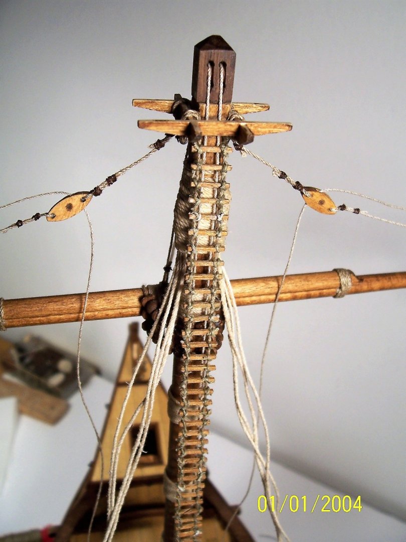
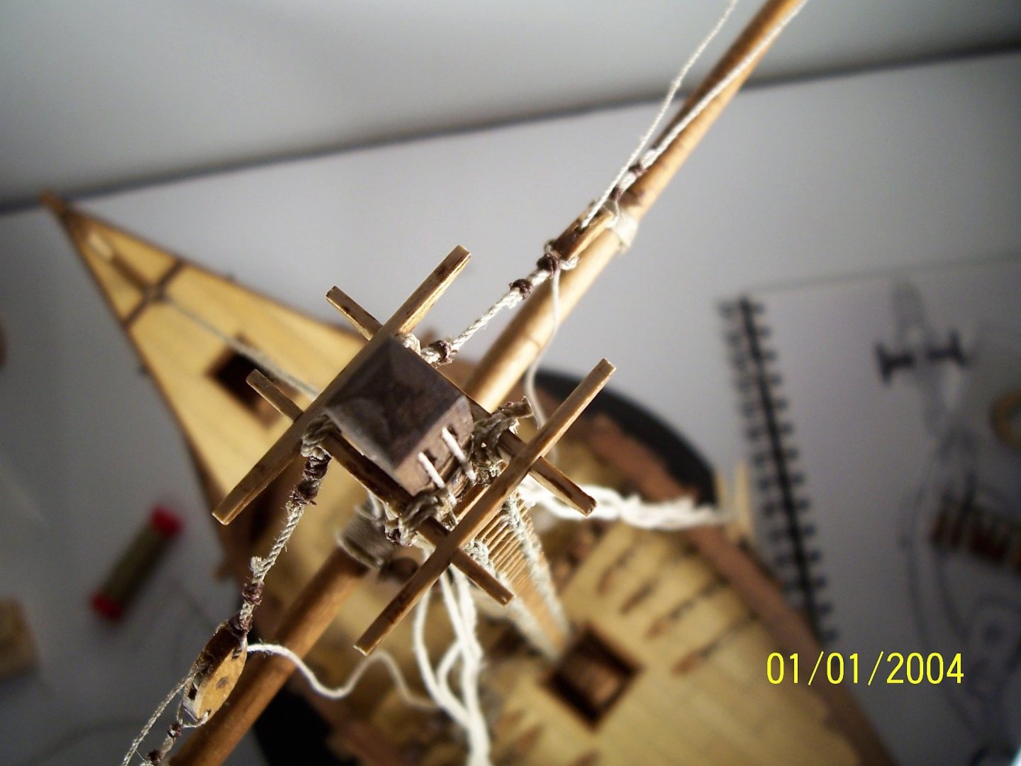
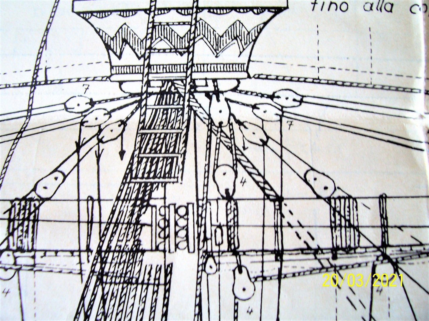
Dear friends, I finally have prepared the cross-tree: and glued it on the upper side of the mast: At the end, after examined a lot of documents, I decided to tie the blocks at both sides of the crosstree, like AMATI's instructions: After that, the rigging starts from the mast block and then runs through hole of the yard block, goes back to the hole of mast block and finally it goes to the quarterdeck rail: Rigging is not yet in tension, because ultimately the yardarm will be positioned at the bottom. Obviously all the blocks are self-made. See you later! Rodolfo


-
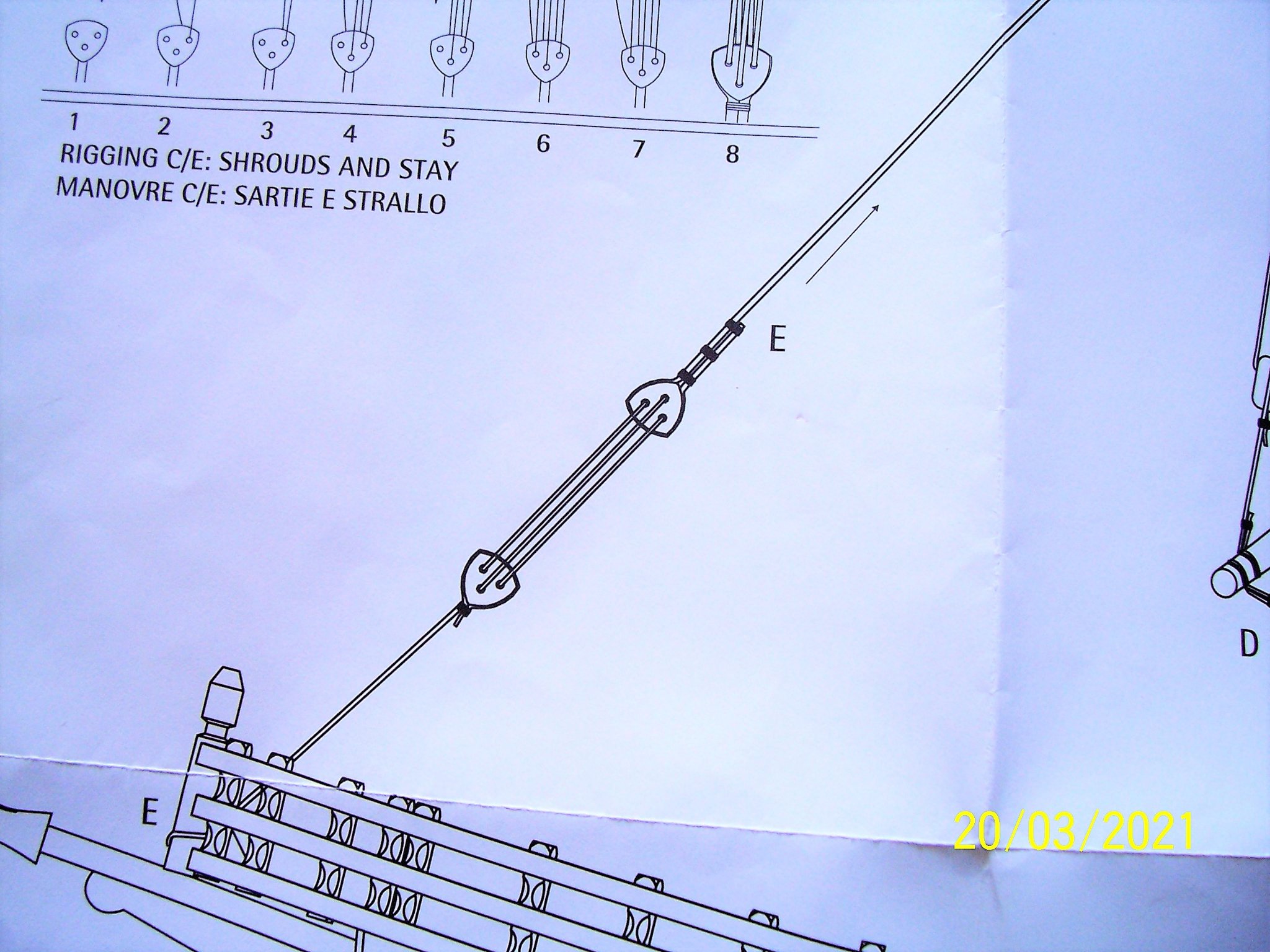
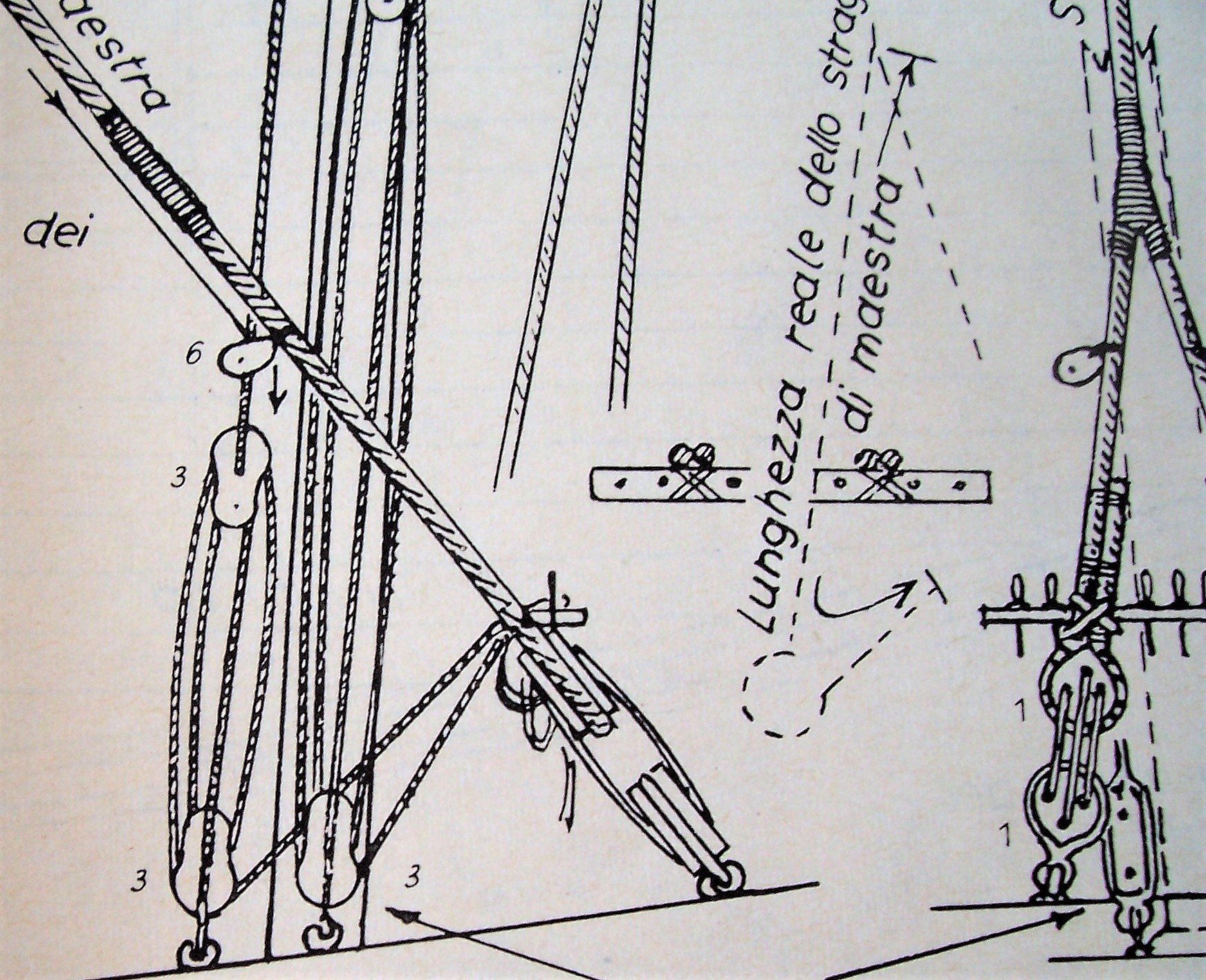
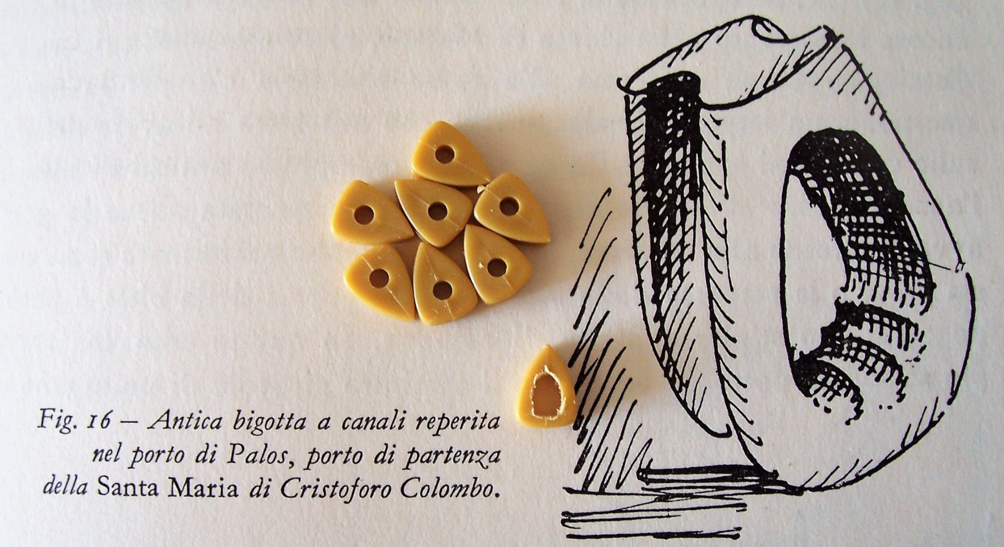
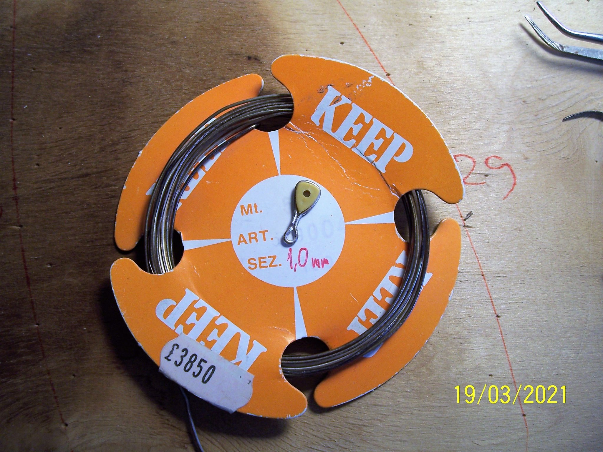
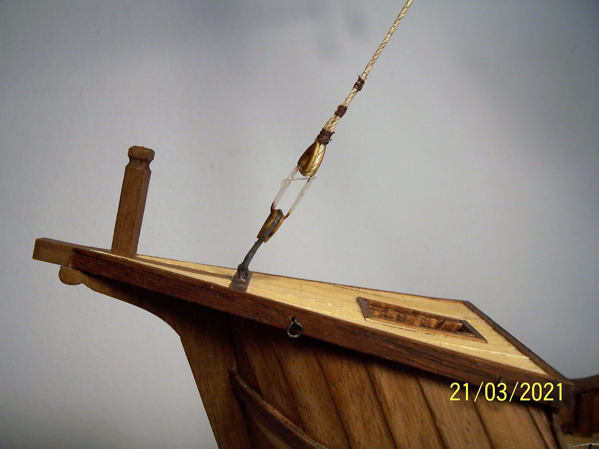
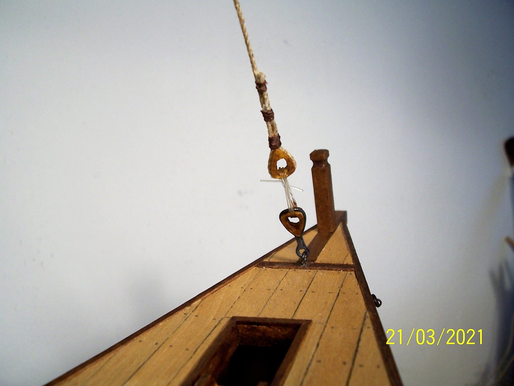
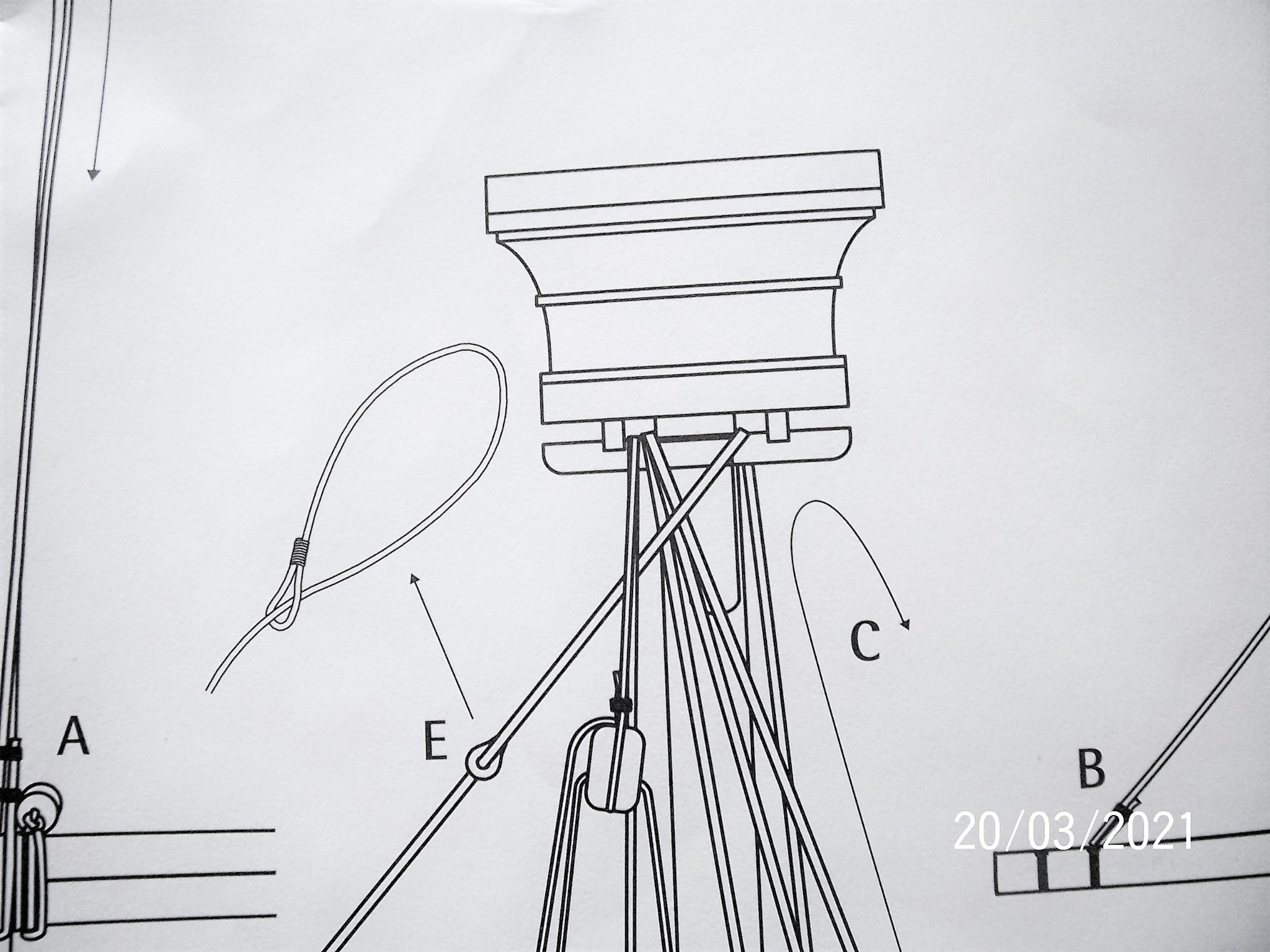
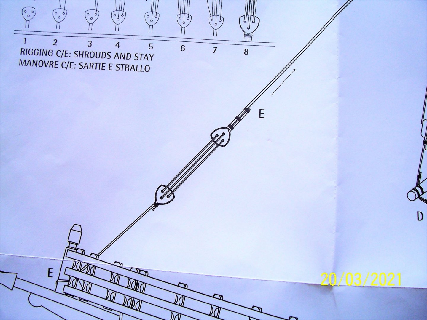
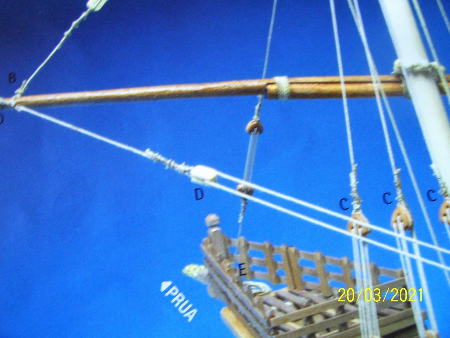
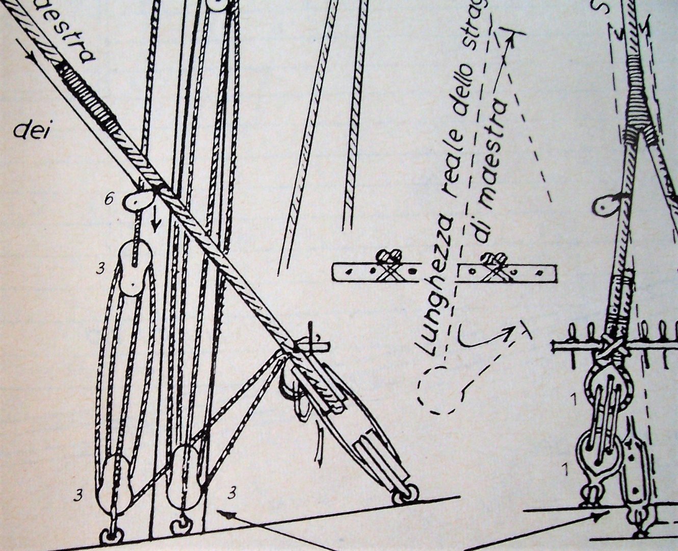
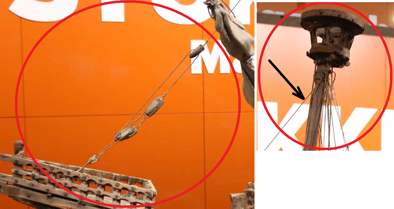
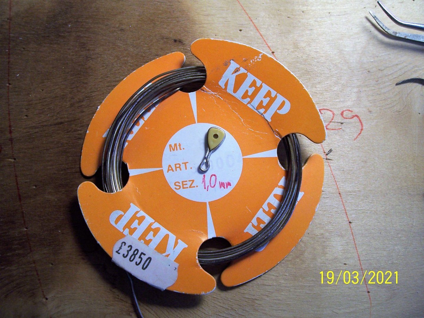
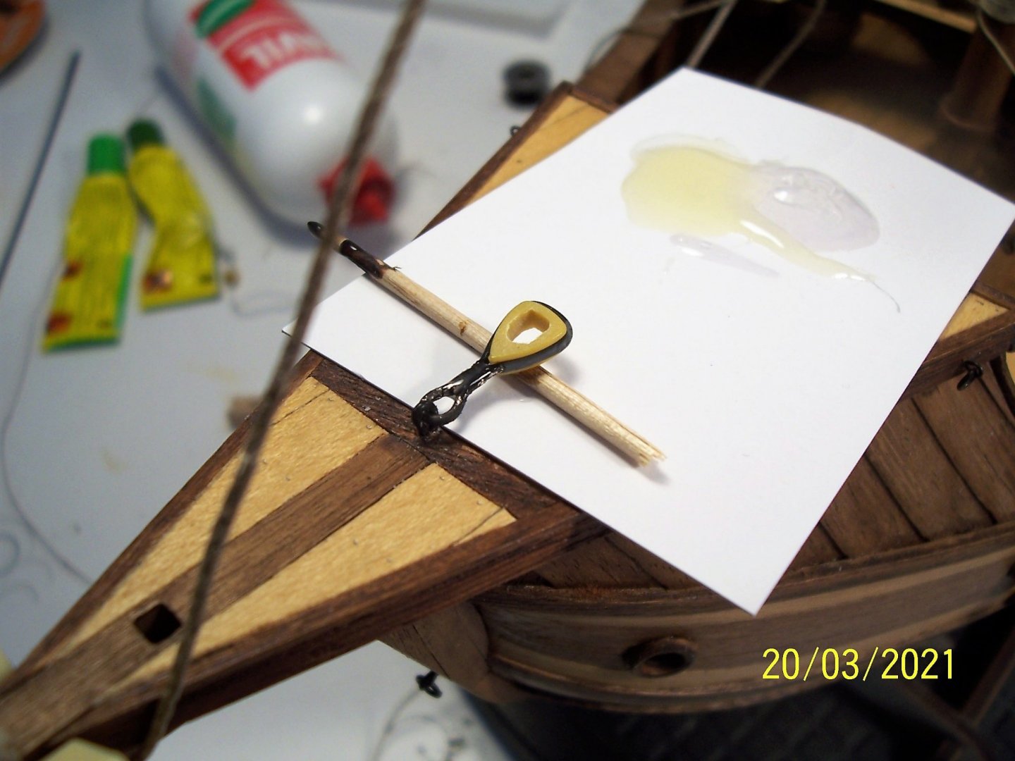
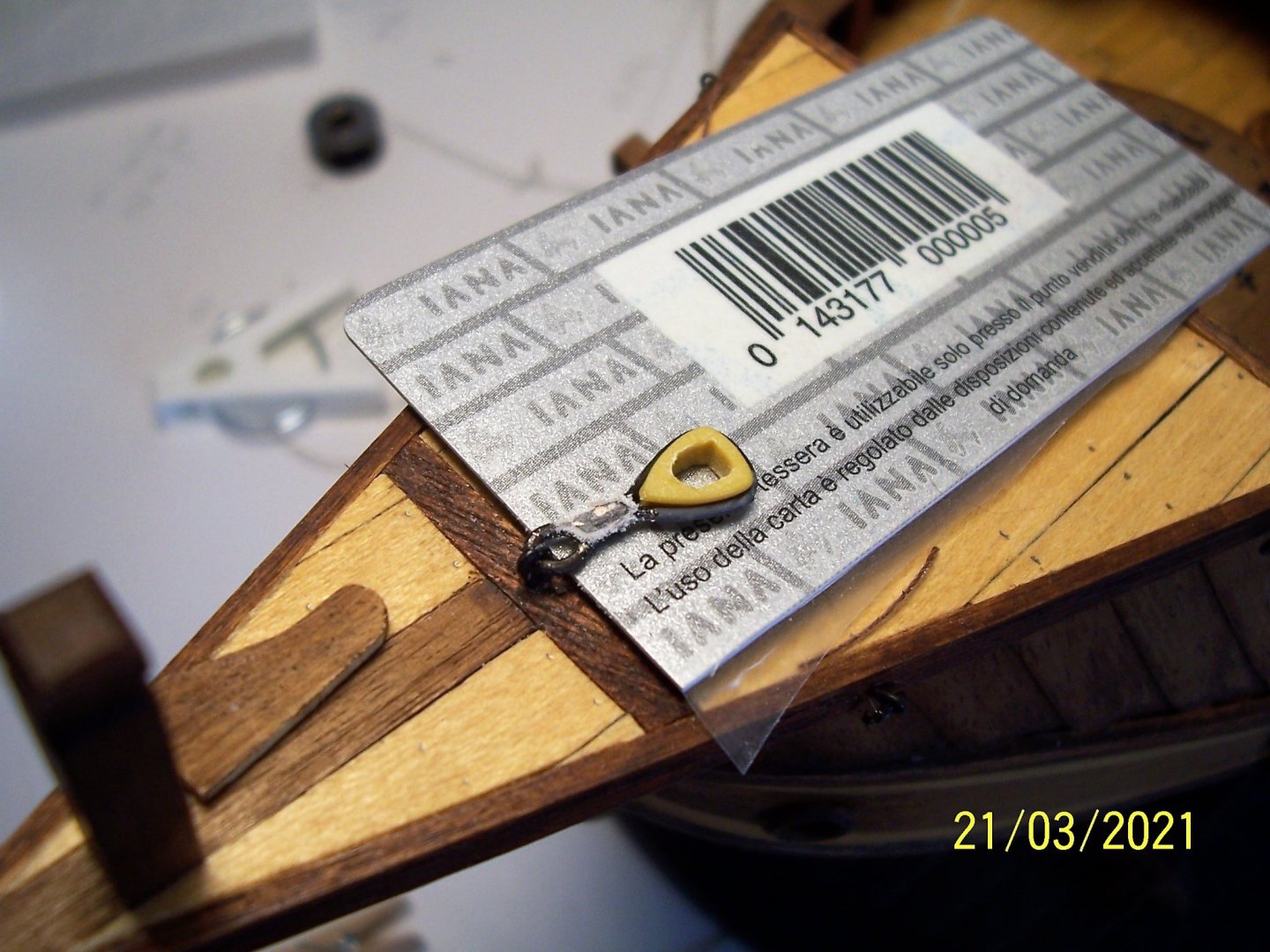
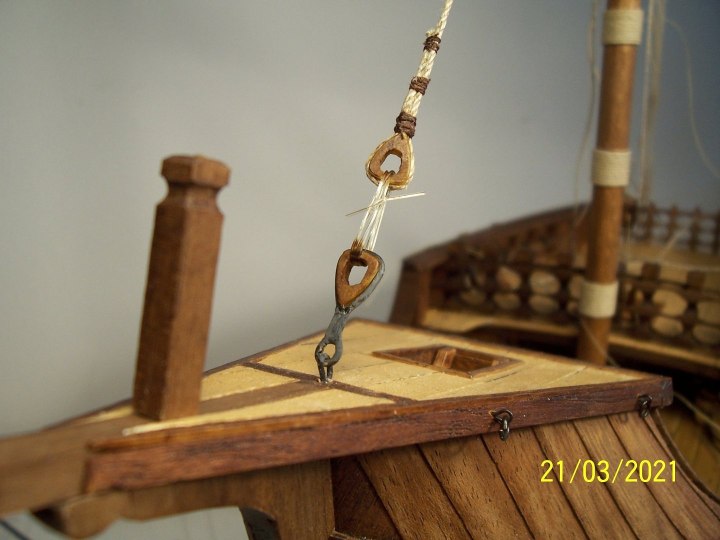
Dear Friends, for the fastening to the deck, AMATI proposes the same three-hole deadeyes that he also uses for the shrouds and it seems to me that he ties the stay to the bowsprit pole (and this seems a not very sturdy fixing): Perhaps this is not absolutely wrong, since H. E. Adametz too, in his plans of Santa Maria (a few decades more recent than the Nao), has put deadeyes on the forestay, but binds it (split) to the deck with rings. The stay and the forestay of the foremast obviously end up on the bowsprit: The Nao of Matarò has a system of hoists and blocks, and it too ends in a ring on the deck: However, since the lateral shrouds will be made with hoists and blocks, too, for the bow I wanted something different, aesthetically pleasing and plausibly not historically incorrect. From H. Winter's book on the Santa Maria, I found a drawing of a deadeye that may have been used for the same purpose (Spanish : bigota de estay😞 At this point I thought about adopting it and enlarged the inner cavity with the file. For the fixing of the deadeye at the deck I chose a metal wire of unknown origin used as a current conductor for the model railways, dating back to the days of the Italian Lira, about twenty years ago. It is not brass as even filing it remains metallic gray. It is very easy to work: Once I cut and shaped the wire, I coated it with two-component epoxy and filed it down to a single bar, then painted it matte black: Obviously the other deadeye is secured with normal bindings. The stay rope is the thickest I had available, about 1,1 mm : A little wood stain to the deadeyes also finished the work. Of course, the clear elastic wire is only there temporarily: See you soon! Rodolfo


-
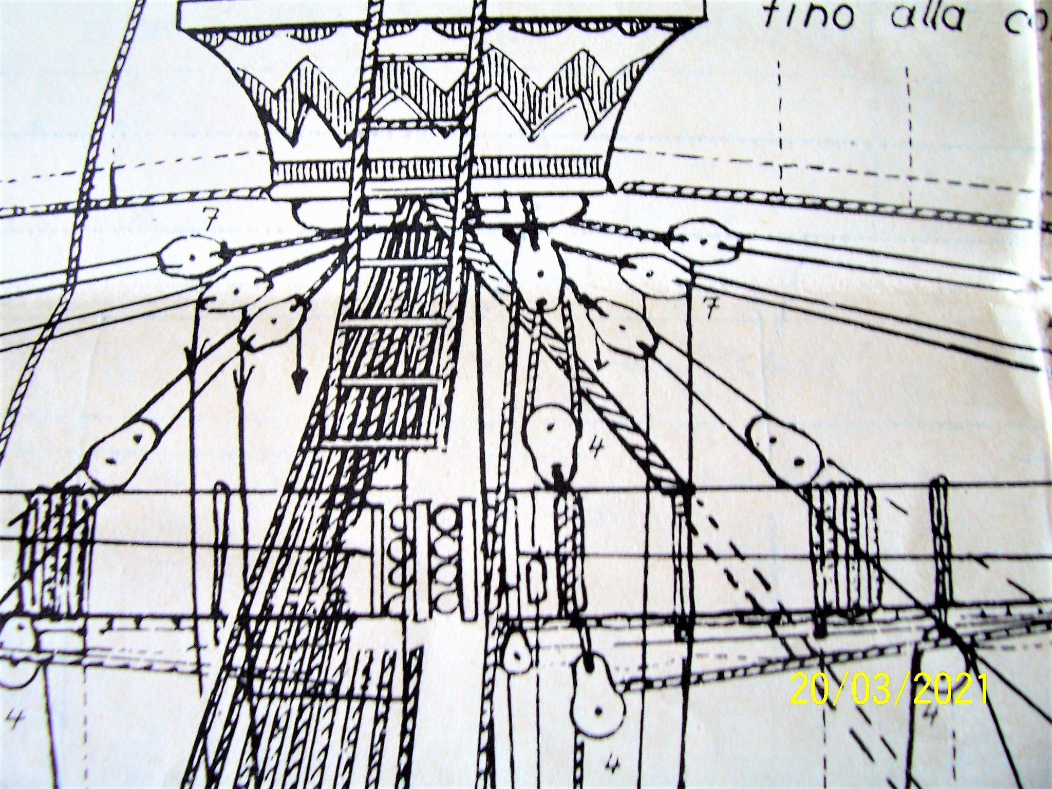
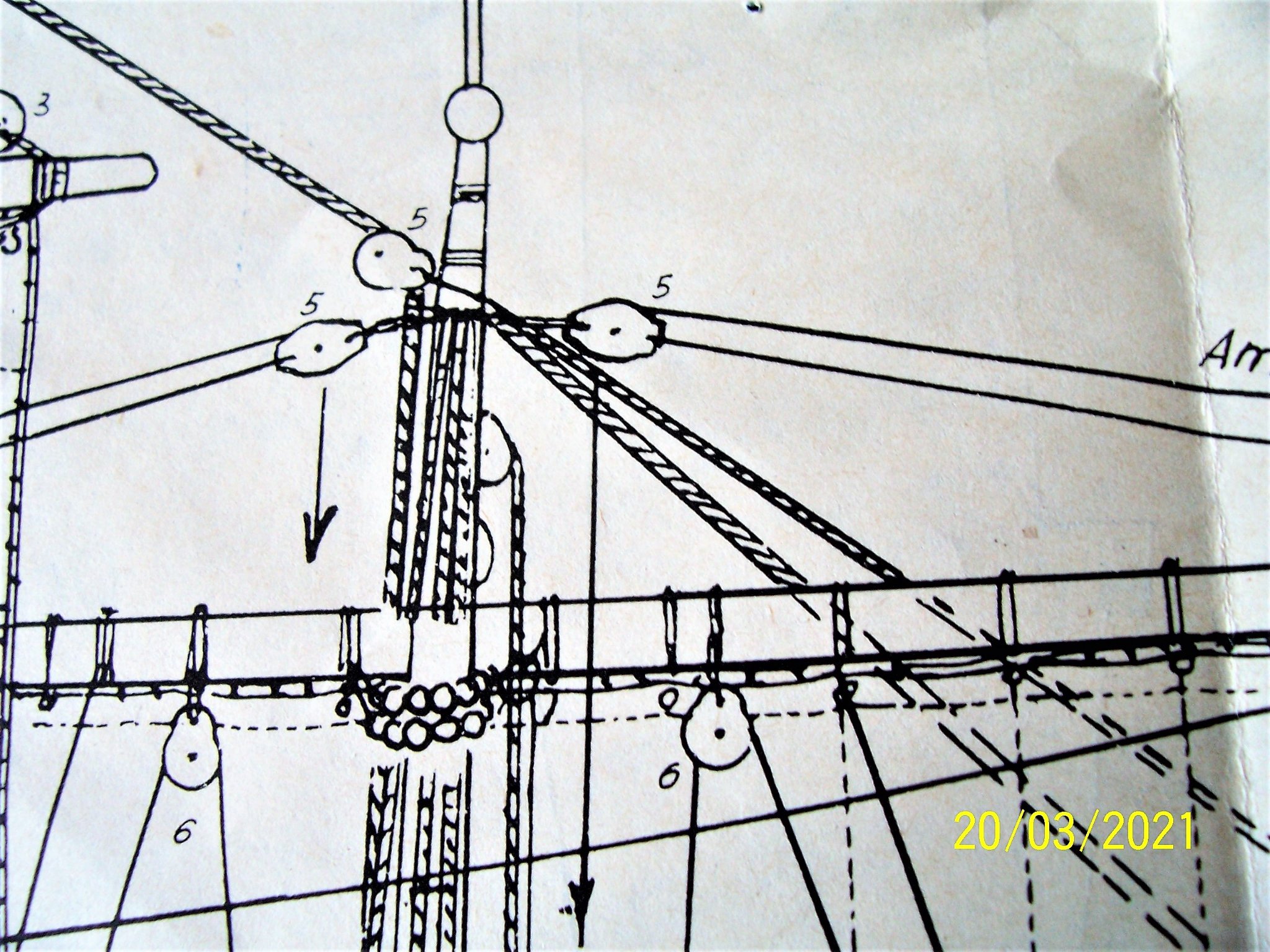
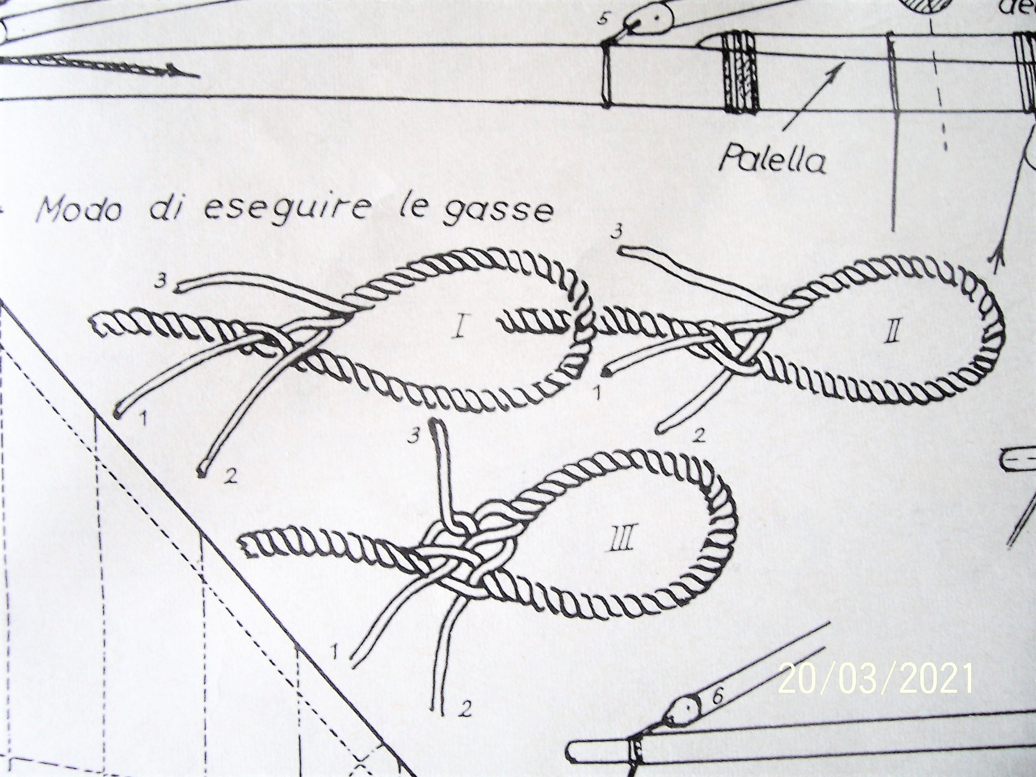
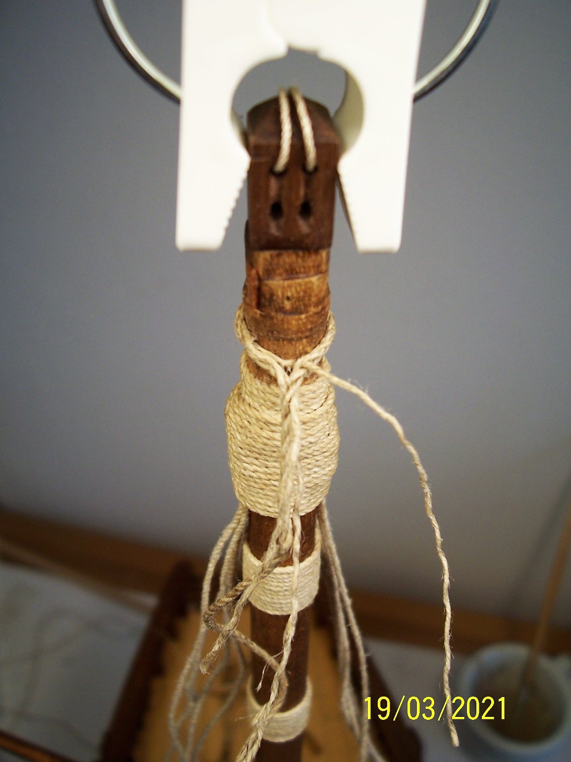
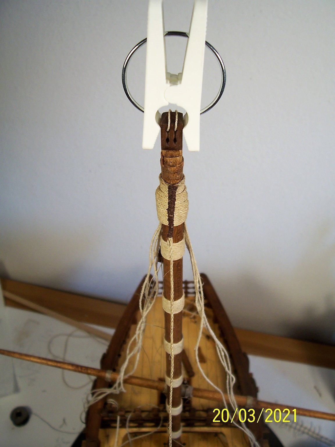
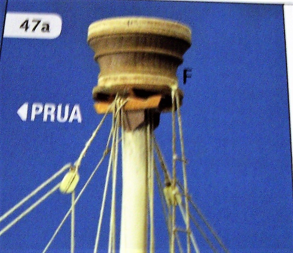
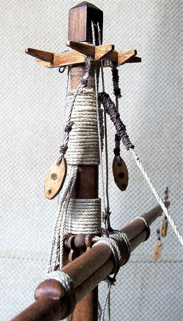
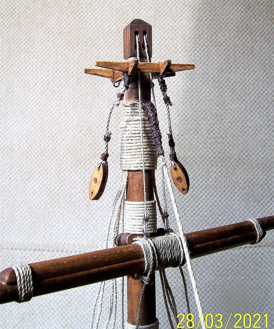
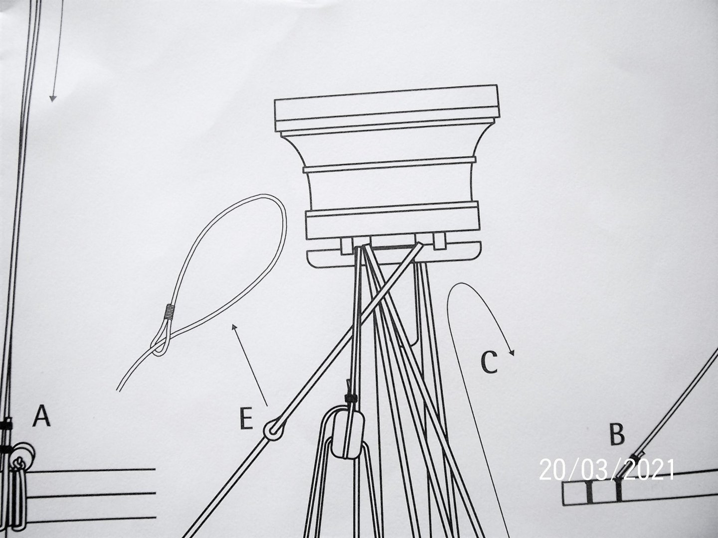
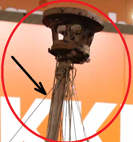
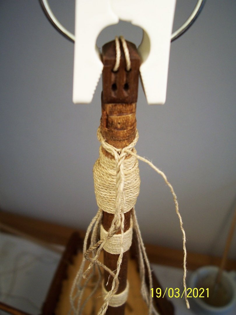
A warm welcome to all! First of all thanks to Patrick and Steven for their words. I have set aside the yardarm to work on the main stay, which is also the only one. For fixing to the mast, the supplier suggests a simple "loop", if I am not mistaken in the terminology, over its top : The Nao of Matarò, on the other hand, has a simple rope emerging out of the tangle of cables under the top: Looking at what H. E. Adametz has done on his Santa Maria, which is a little more recent, we will find a very impressive binding on the main mast, but something much smaller on the foremast, perhaps done with a bowline: I thought it might also fit on my Cocca: Next step: the attachment to the bow deck. See you soon! Rodolfo

-
Hi Chuck, I had a similar problem myself. I solved with a second layer of varnish on the lighter wood; it could make the difference much more nuanced. A very light sanding on the darker woods would make them lighter... Rodolfo
- 130 replies
-
- 3
-
-
- wütender hund
- hanseatic
- (and 2 more)
-
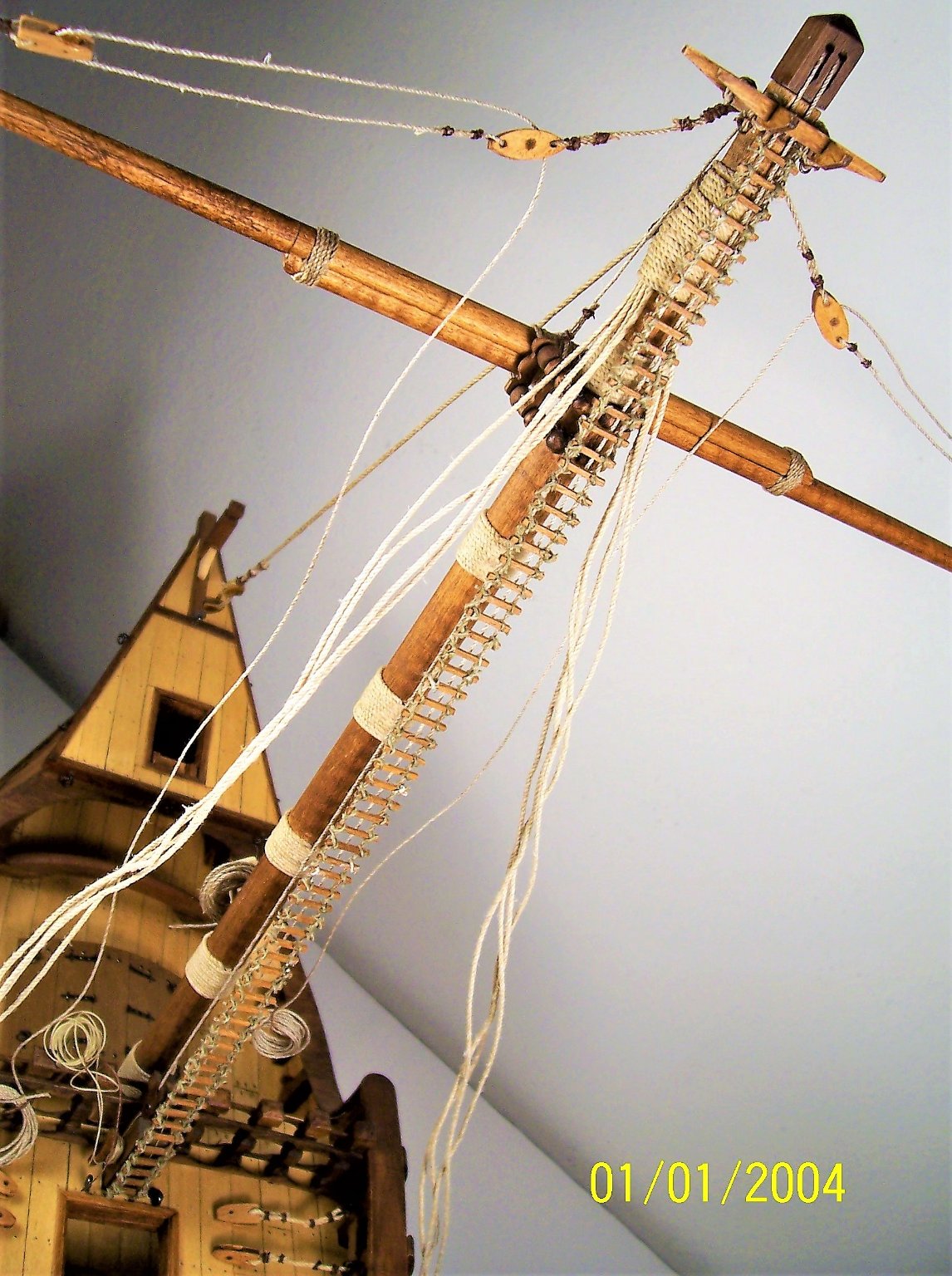
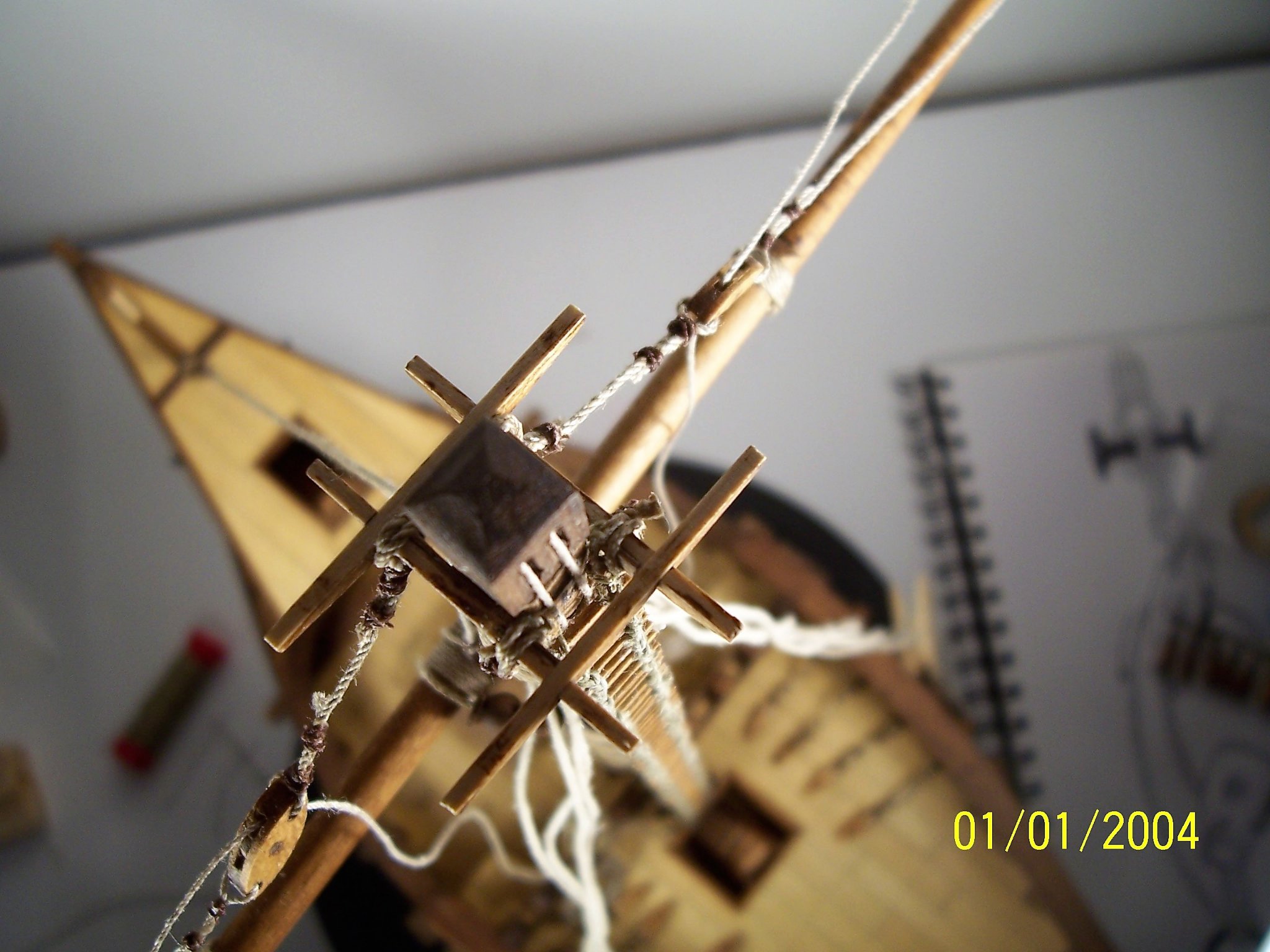
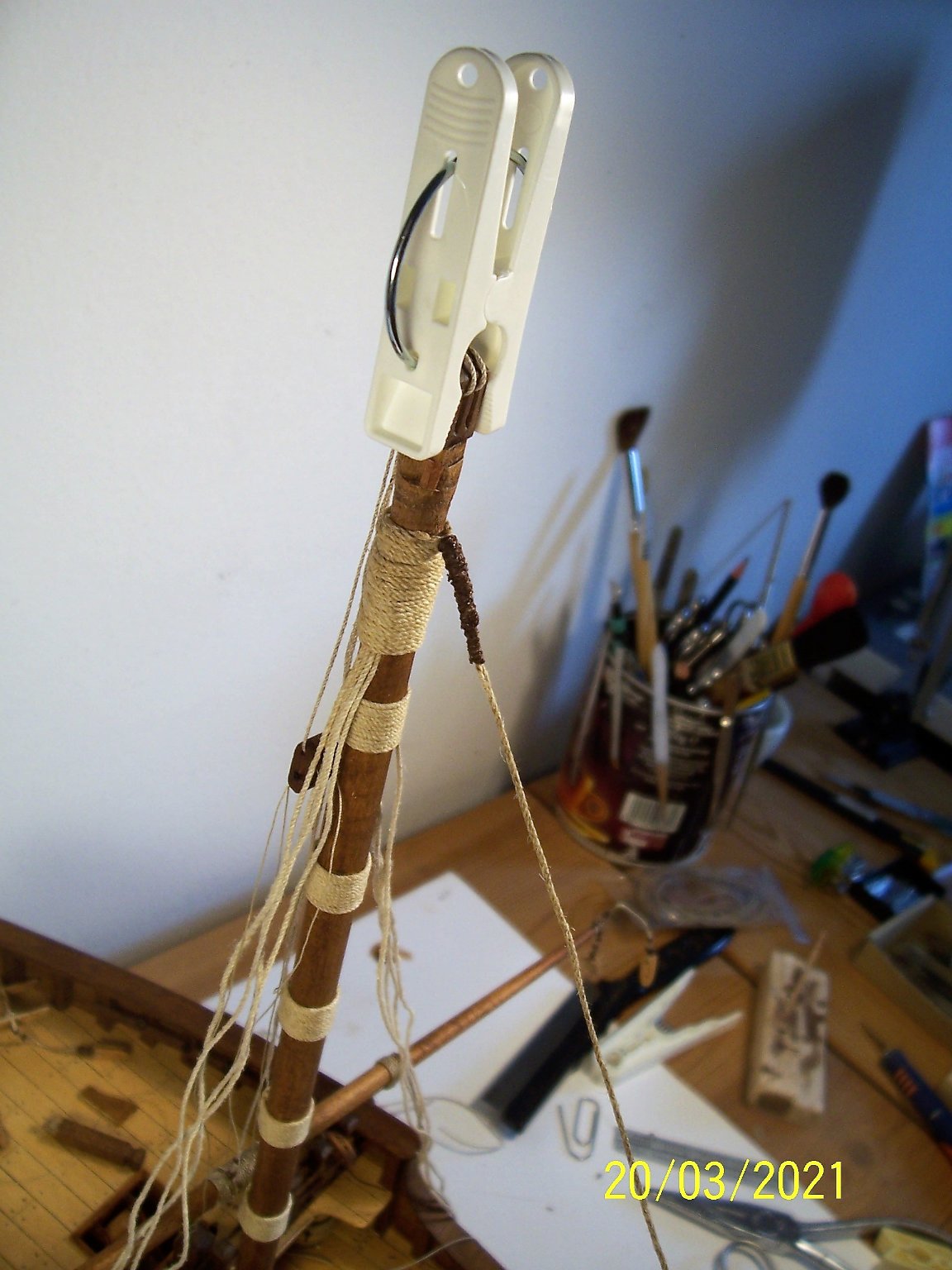
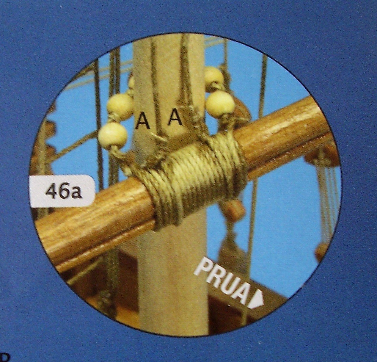
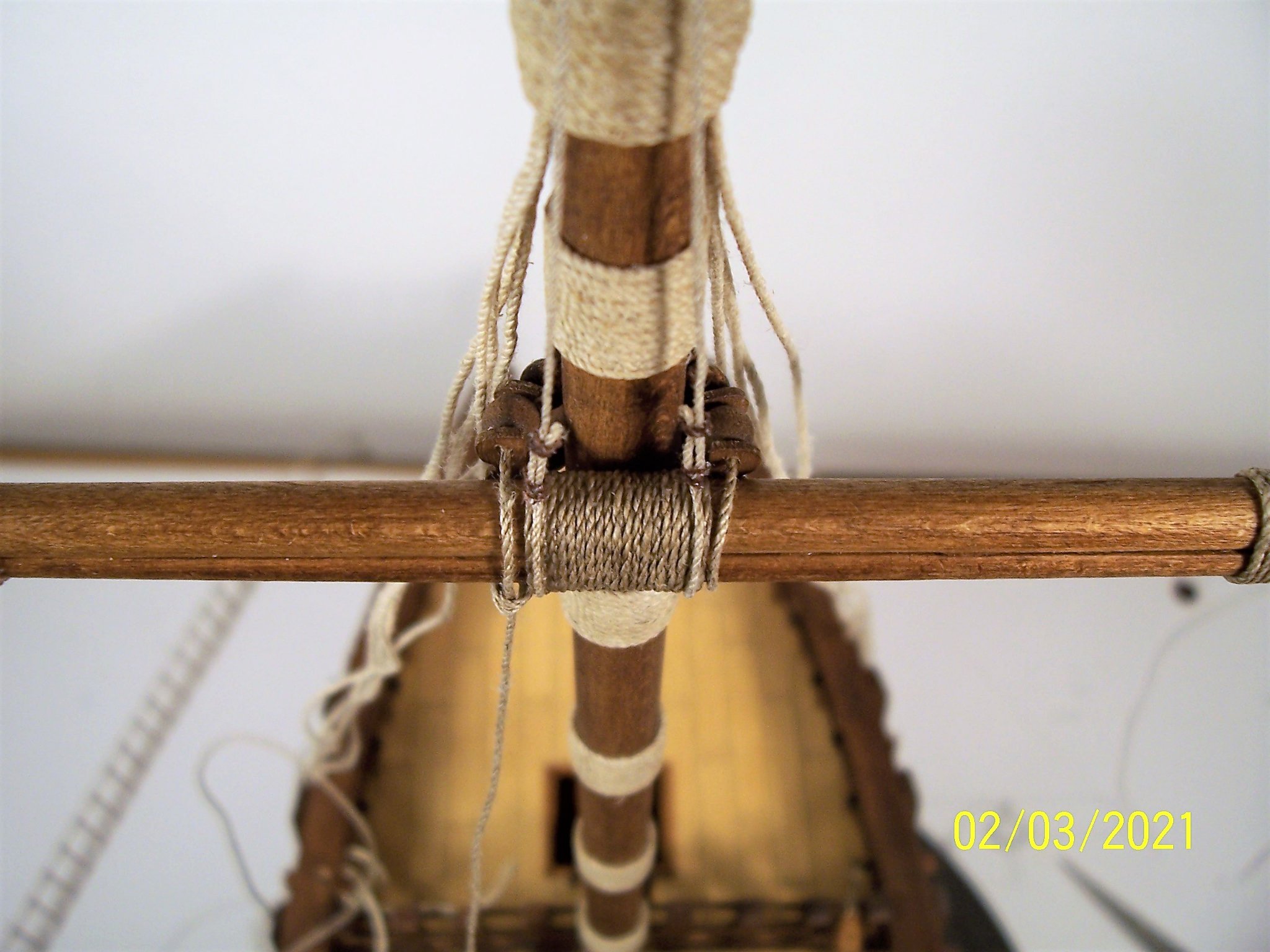
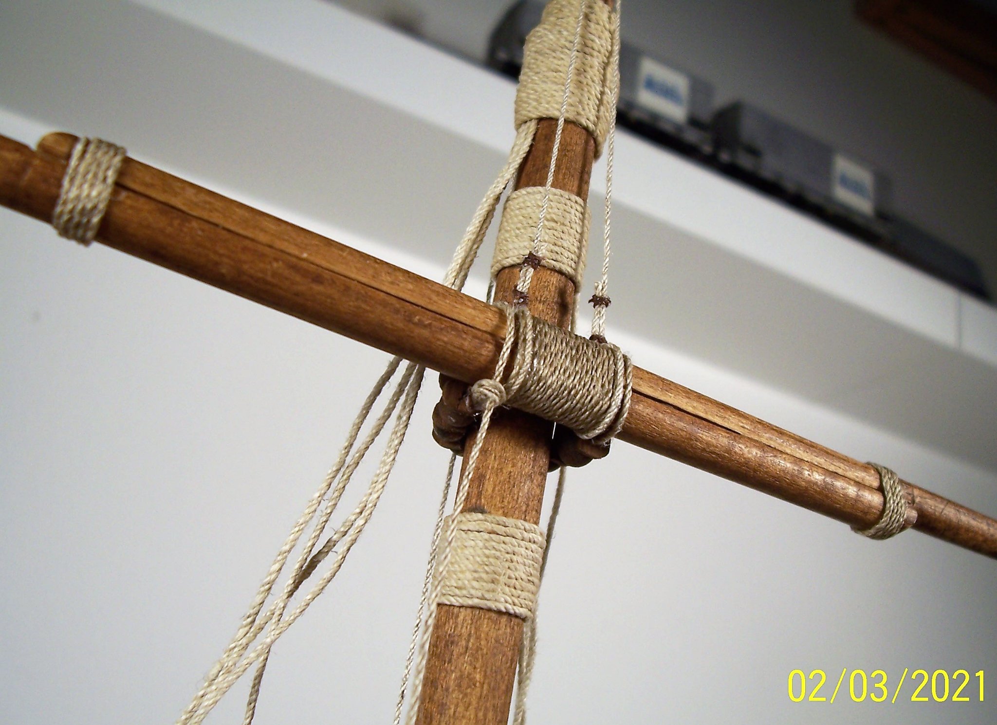
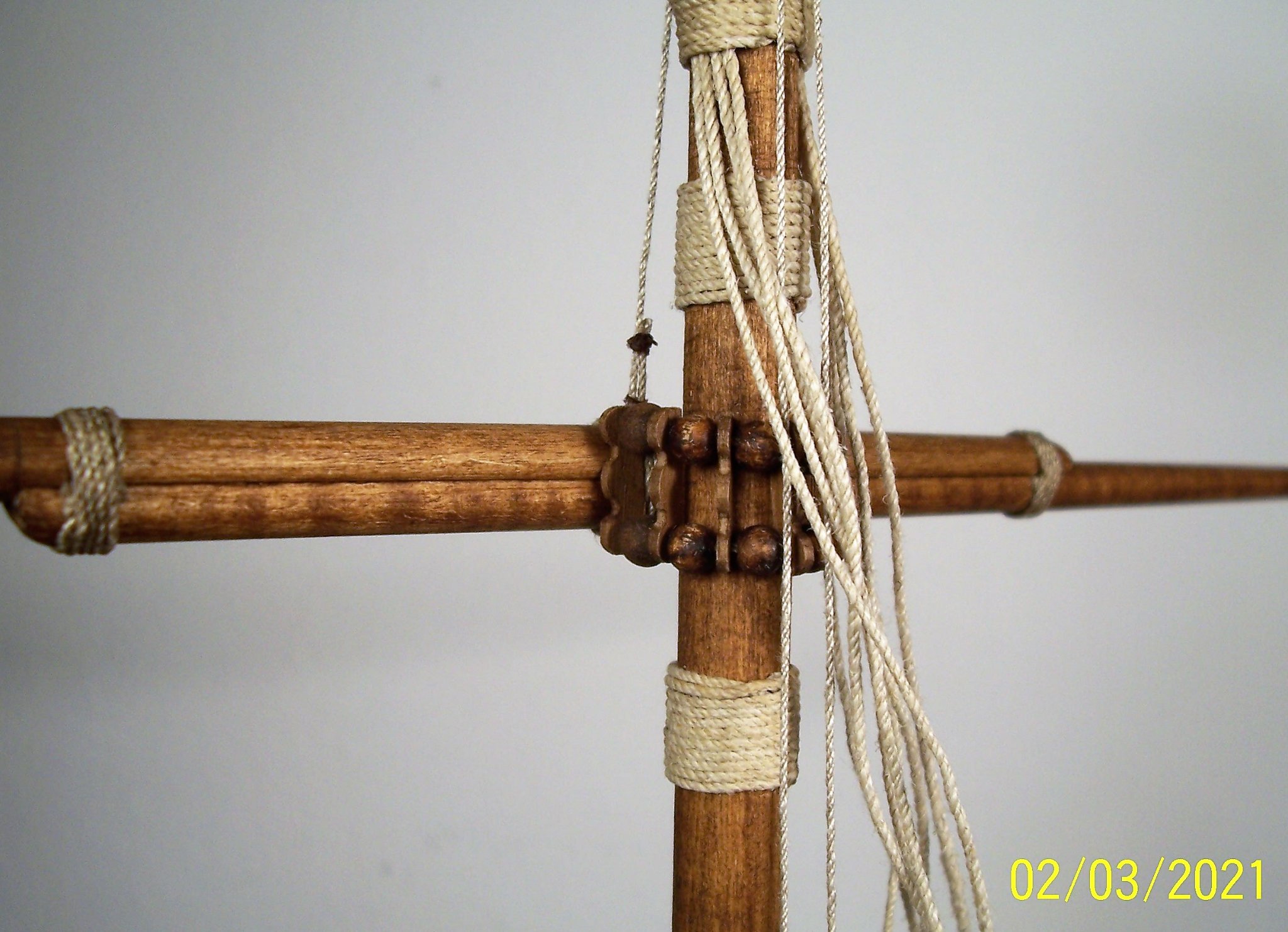
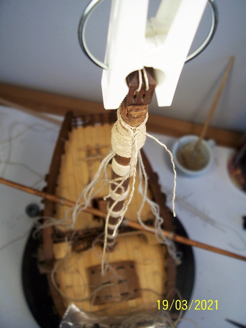
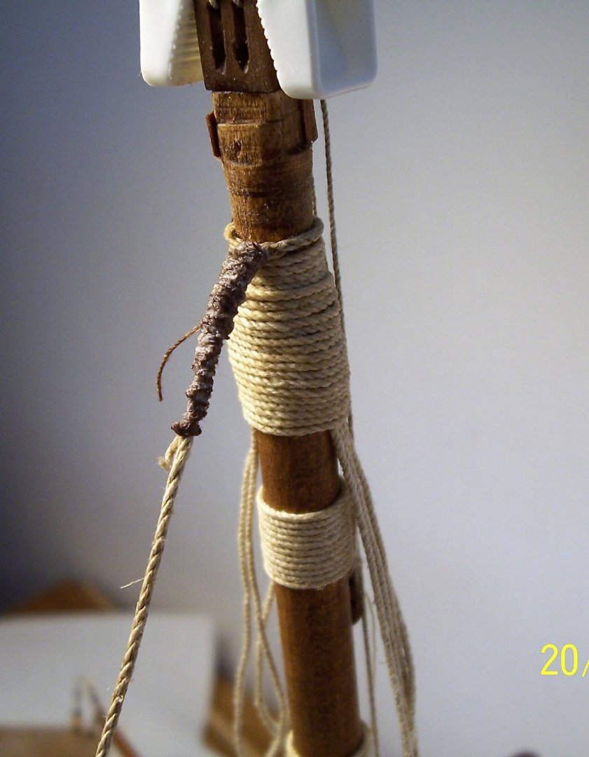
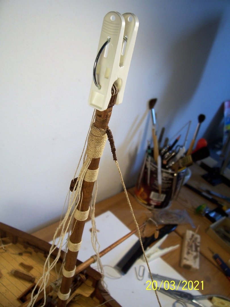
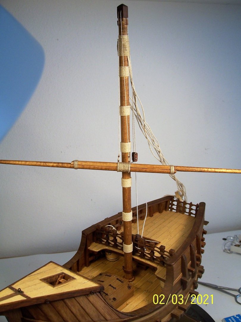
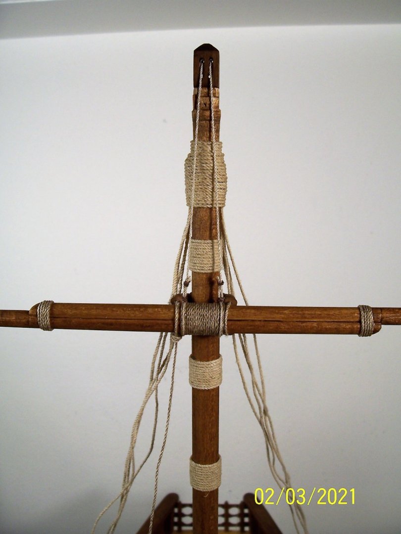
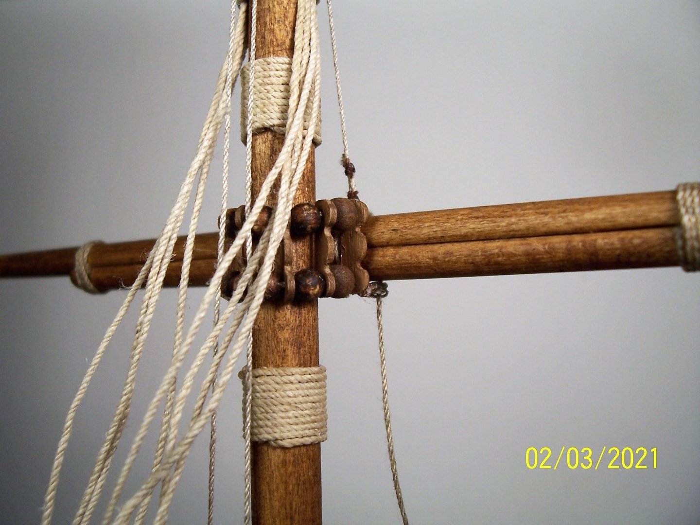
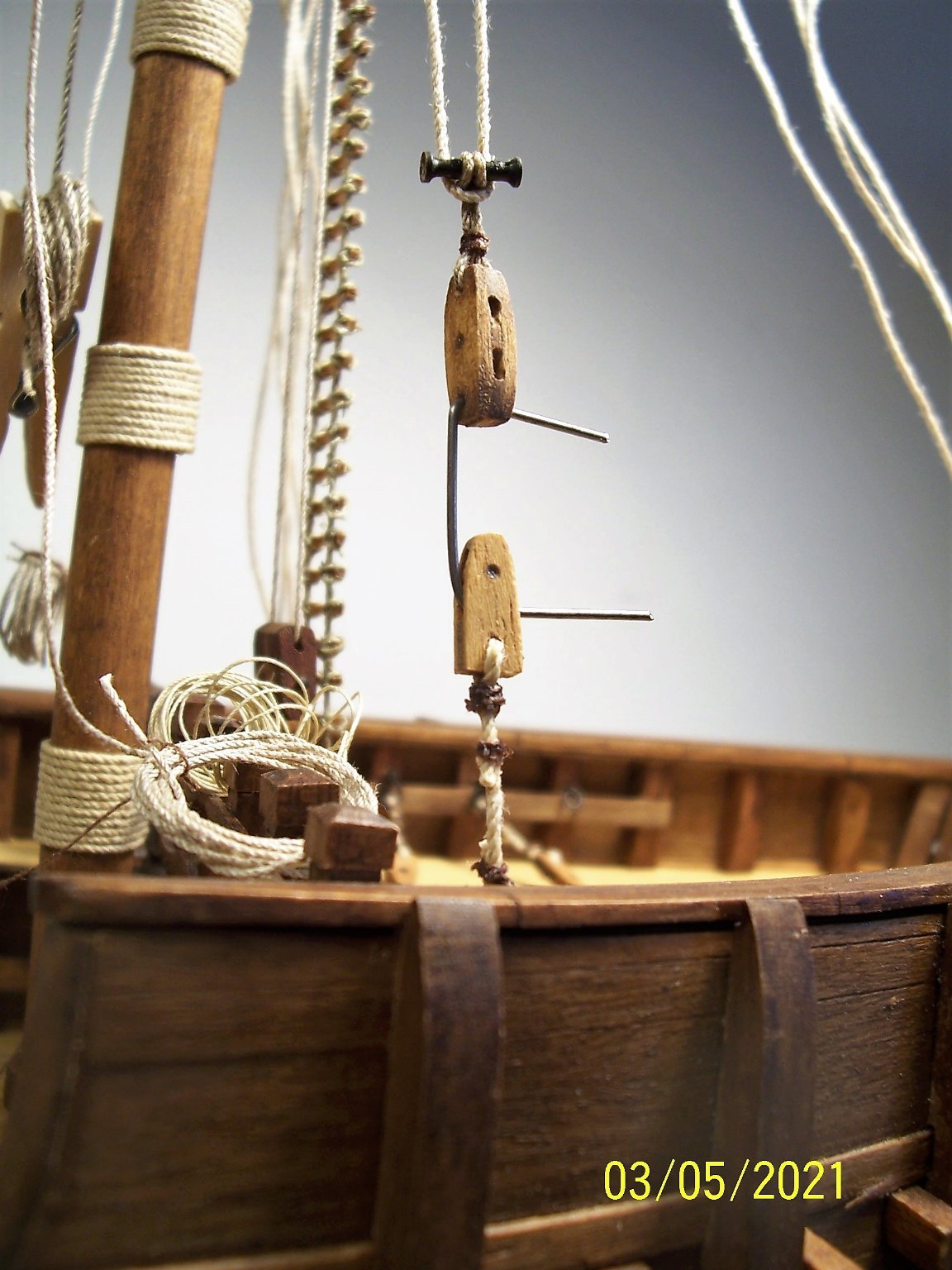
A Welcome back everyone! I'm now on my fourth attempt at mounting the yard. First, I arranged for the halyard to be long enough so that the yard and block would cross at mid-mast height, considering that I'll be setting it very low and with the sail folded (if I'm able to do so, otherwise it will remain without sail): Since it is clear from the instructions that the halyard is tied on top of the ligature: I increased the length of the ligature: Also, the bindings depicted in the instructions look a little coarse to me and I modified them using a thin wire of another color that was in the package. After that, I put the parrel, for now only leaning against mast and yard. I will glue it only at the end. Moving on to the halyard tackle, here depicted in instructions: I used a thinner wire than the halyard itself and I think I'll color the pinheads that simulate the pivot of the pulleys black: Now I have to tie a few knots on top of the block to secure the rigging... See you soon and happy sawdust to you all! Rodolfo.


.JPG.212fef067b672b29f02178a23a1e75ca.JPG)
.JPG.48d199913f4bc610e2cd5081d205cf77.JPG)
.JPG.bfc435fcf31d0c2ffb8a8032fa876f78.JPG)
.JPG.4497fef9ce26c555d24edd606c9d81ae.JPG)
.JPG.fa897f1c6d1551e35503ac3648d3b146.JPG)
.JPG.5eb8861f1c9459d9c119c9c9e21c7a86.JPG)


.JPG.aee20a004b566f3caaccf68e60b38c39.JPG)


.JPG.ee0b3e9c1a5b7944da1be36e022e5430.JPG)
.JPG.02cb2b2dba03a95b68dae15978534271.JPG)
.JPG.8aefdc0b3a6d6c9dfb06b8a23c665d31.JPG)
.JPG.e3c8d2996feea0058766e5759a3c588b.JPG)
.JPG.398a5f09a7c2cbe5330d383960a4e92f.JPG)
.JPG.6ca096ae9739db987d012243f674479a.JPG)
.JPG.48ef07156effb0bac374a70dc44d9804.JPG)
.JPG.108bb87820a41ea5302132e65a9e719b.JPG)
.JPG.357d5ff4a860285efc190406acbfe616.JPG)
.JPG.aede162d0a8cce6606733eea84392f45.JPG)
.JPG.27a2dfdc53530ee5f485c9636123ccae.JPG)
.JPG.aed19451596254e19a1efc18e5bcd3e0.JPG)

.JPG.e14839062b3e9ef1f9e9c594f3918588.JPG)
.JPG.71bfcad275598946ef04e571702b8832.JPG)
.JPG.f462ba748454547c88a46951db348844.JPG)
.JPG.0d2fa035900376a1c5c183e29dd43f62.JPG)

.JPG.0161e3a34611311f48879e89b9762927.JPG)
.JPG.e4bb6ee9dd12a423a001fa321fd55fed.JPG)
.JPG.3345f8b7f0e5007d361929cc535c5367.JPG)
.JPG.19eeaa4940350784d453a172f9fe092f.JPG)
.JPG.5f2ebe12b390ede197da2c92c3b78989.JPG)
.JPG.f63b083c39ea22537e48be8b3c2c508d.JPG)


.JPG.8d43958aee5cabf48cc8ec1c81b8a0f0.JPG)
.JPG.69c6263108a1b336eb57bf6b6cff6ee6.JPG)
.JPG.be2172bef9e80fc0fd426f51de115dd8.JPG)
.JPG.ee7937402bfaf324e667d6e089802fe0.JPG)