Rodolfo Bigoni
-
Posts
118 -
Joined
-
Last visited
Content Type
Profiles
Forums
Gallery
Events
Everything posted by Rodolfo Bigoni
-
 Hi Kev, to avoid bleeding of the colors I used a very fine brush and great care where there was a separation between the two types of strips and a regular brush where there was wide space. An alternative that I haven't tried, could be to paint (only) the external visible part of the strips before gluing them. Have a good work! Rodolfo
 -
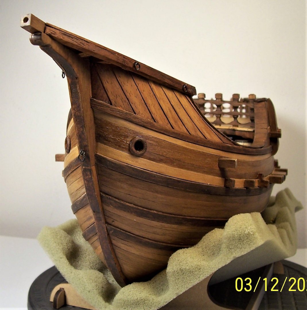
Hi Steven, I'm glad to have been helpful! Hi Kev, no magic tricks. As you may have seen, the first planking was laid very carefully trying to achieve the maximum of the symmetry. This is important because in this way you have the references for the laying of the wales. The wales are painted with the remainder in the bottom of a can of dark walnut impregnating agent. In fact, the bottom of the jar is very rich in pigments and gives a very dark, almost black shade. The second planking is made of walnut strips, inserted in the space between the wales. They were varnished with the same impregnating agent used for the wales, but taken from a new package, with the pigments well dispersed in the liquid. This gives the lighter walnut color of the strips. The paler strips are made from lime wood, varnished with oak-colored wood impregnating agent, very clear. Be careful to avoid traces of glue, which leave stains between the painted surface! Until next time! Rodolfo
-
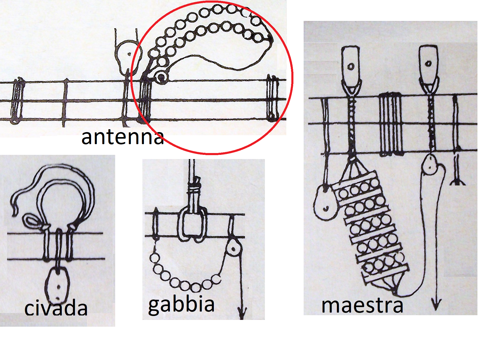
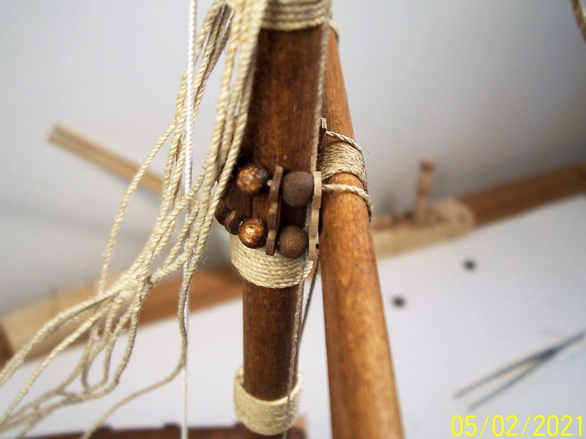
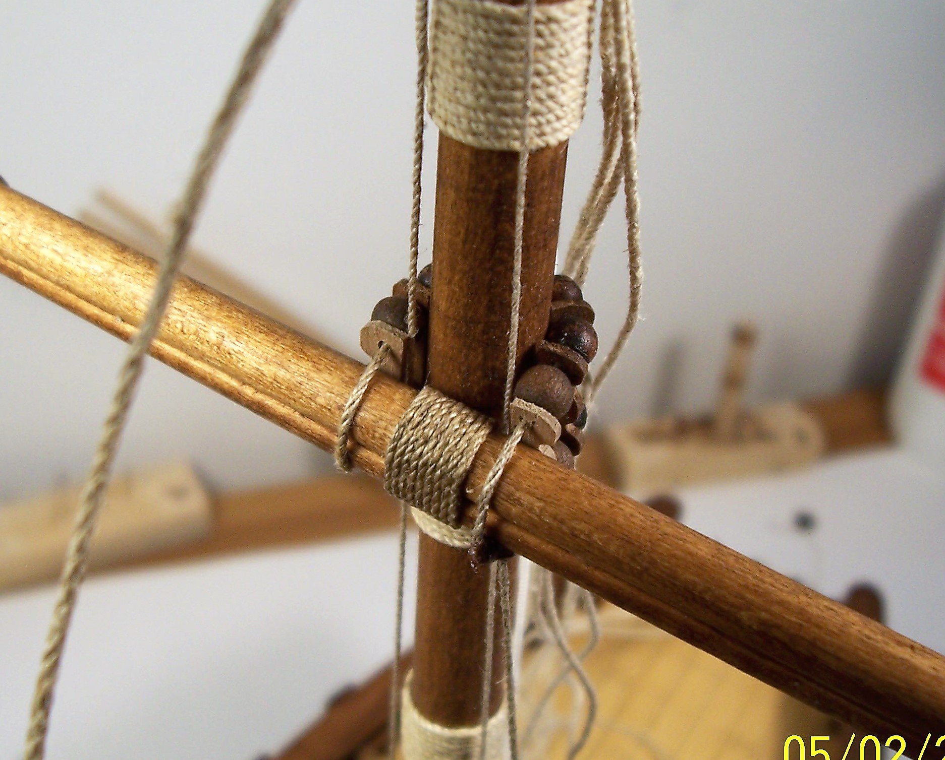
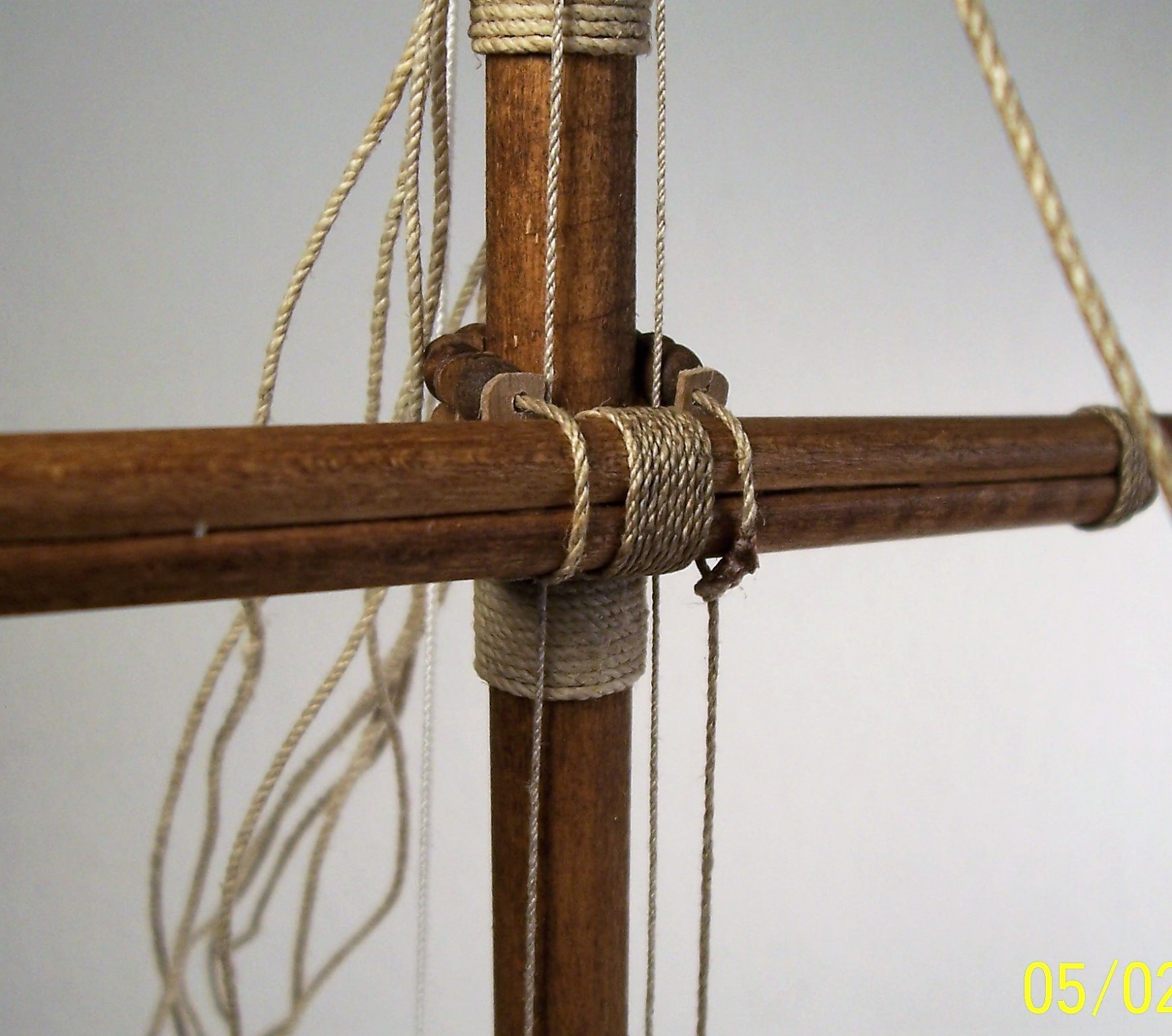
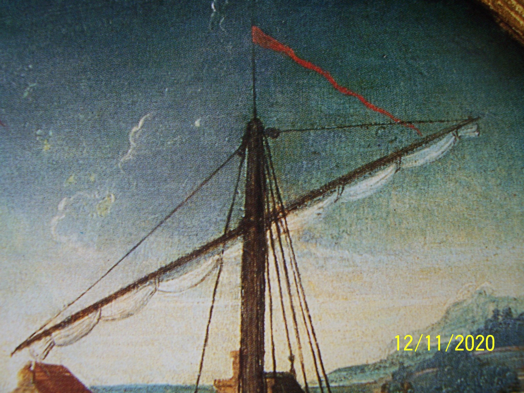
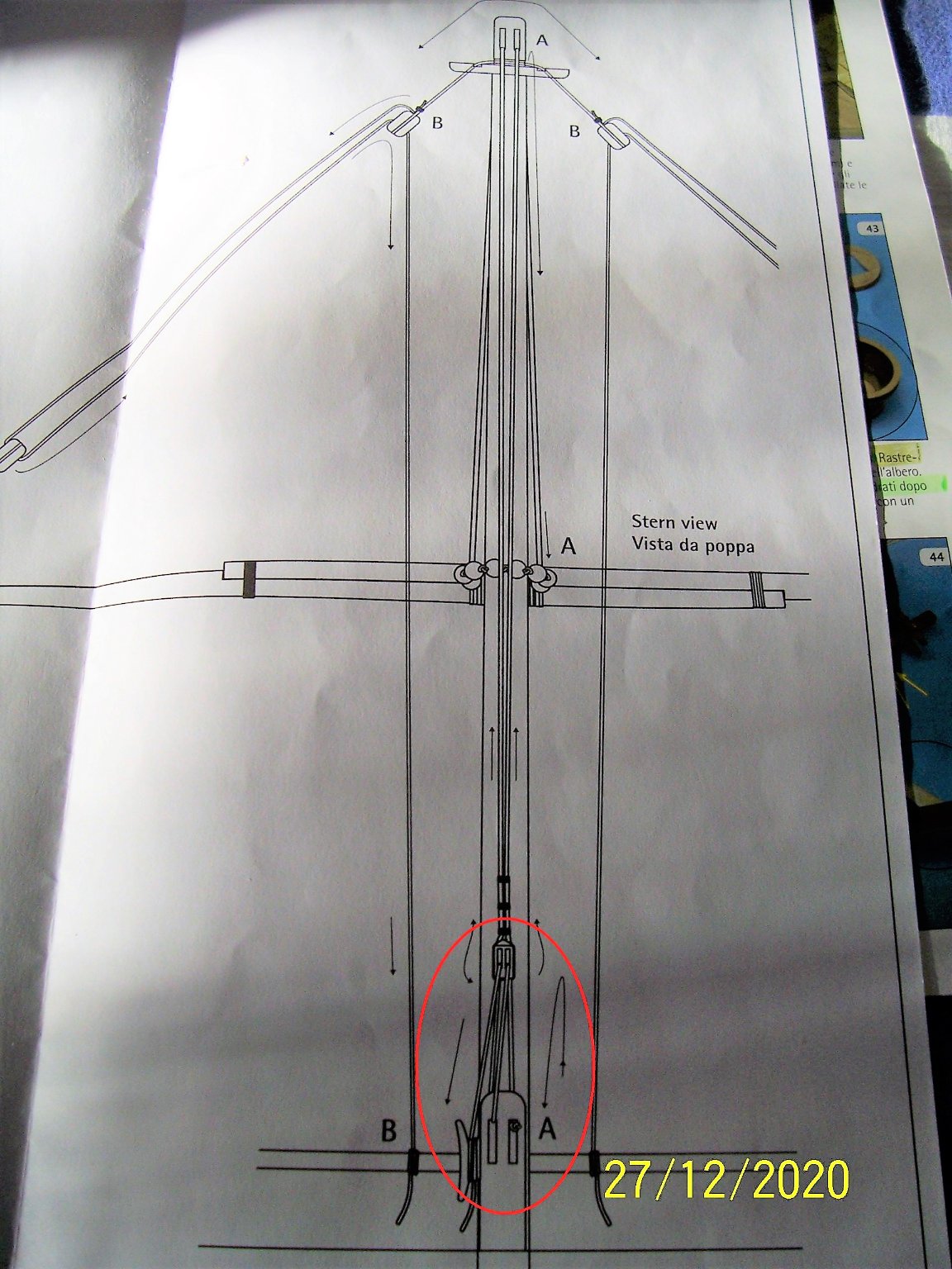
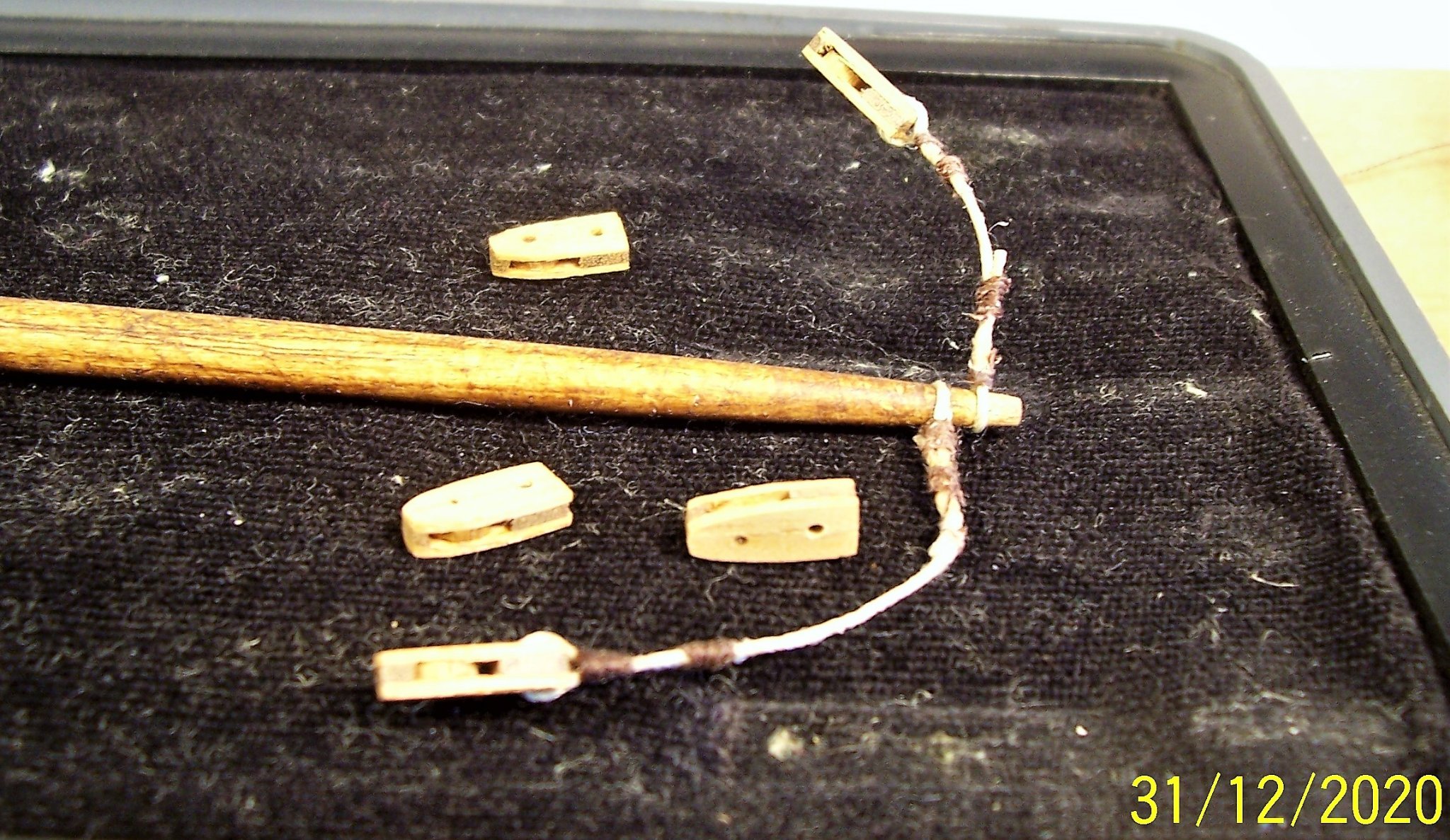
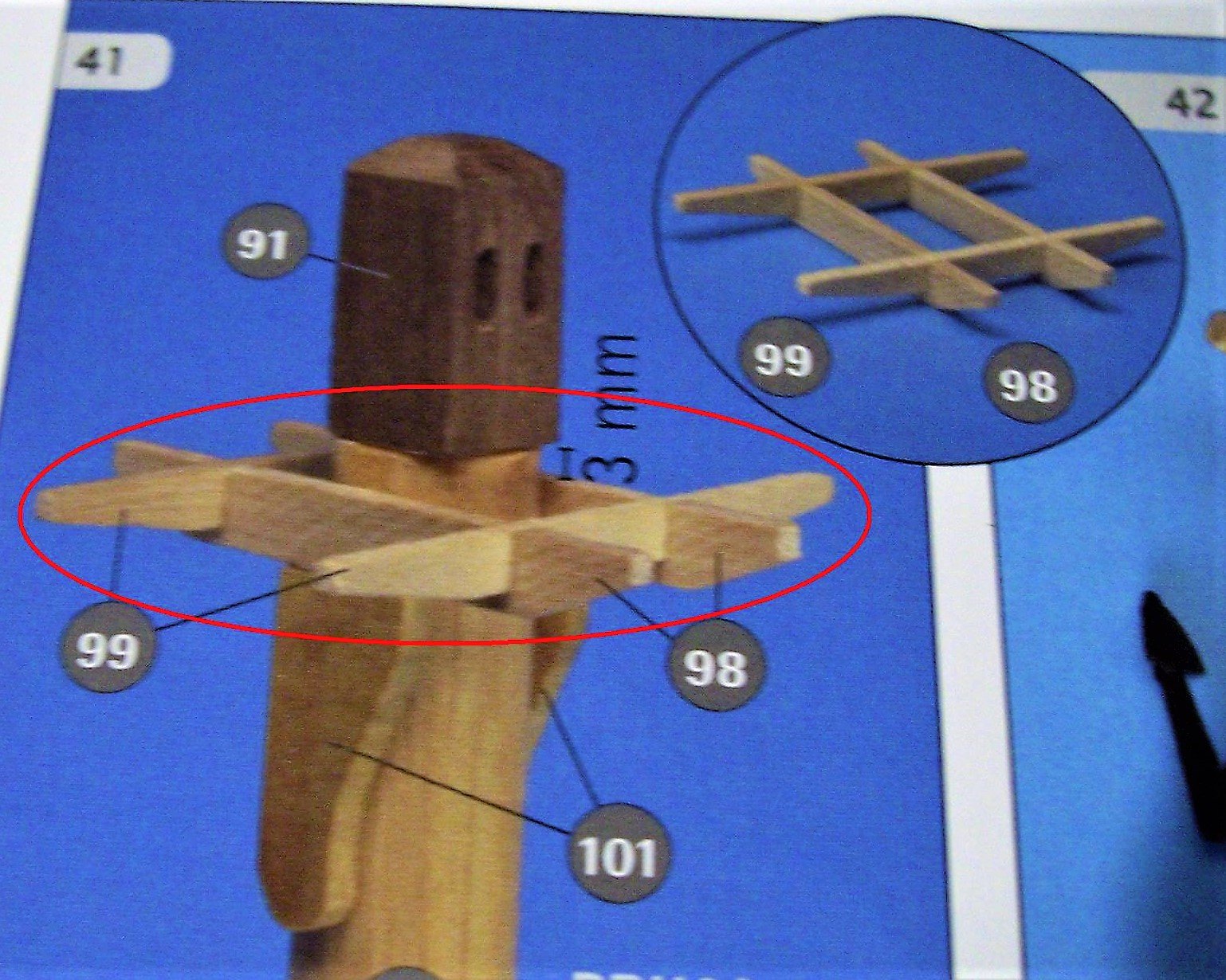
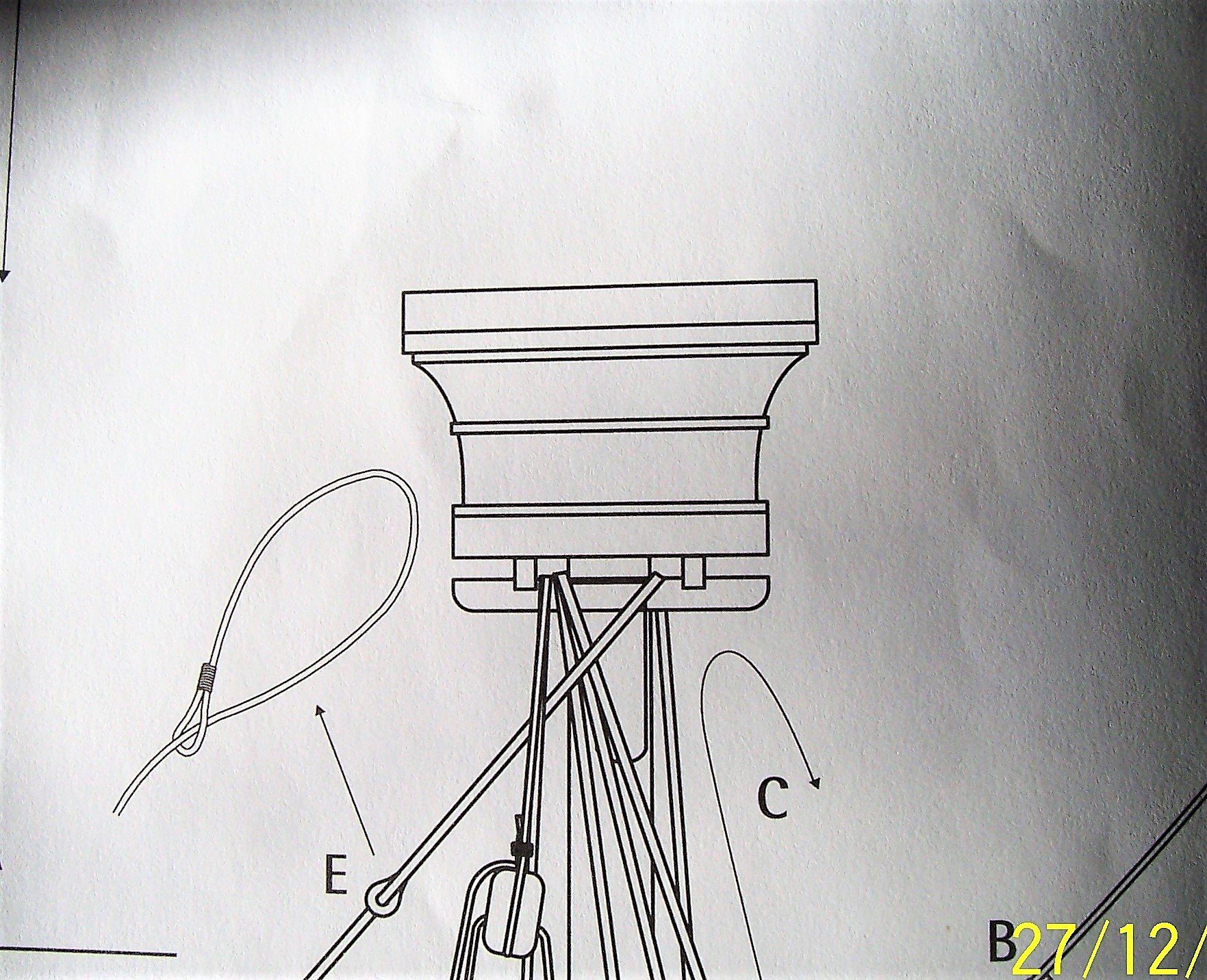
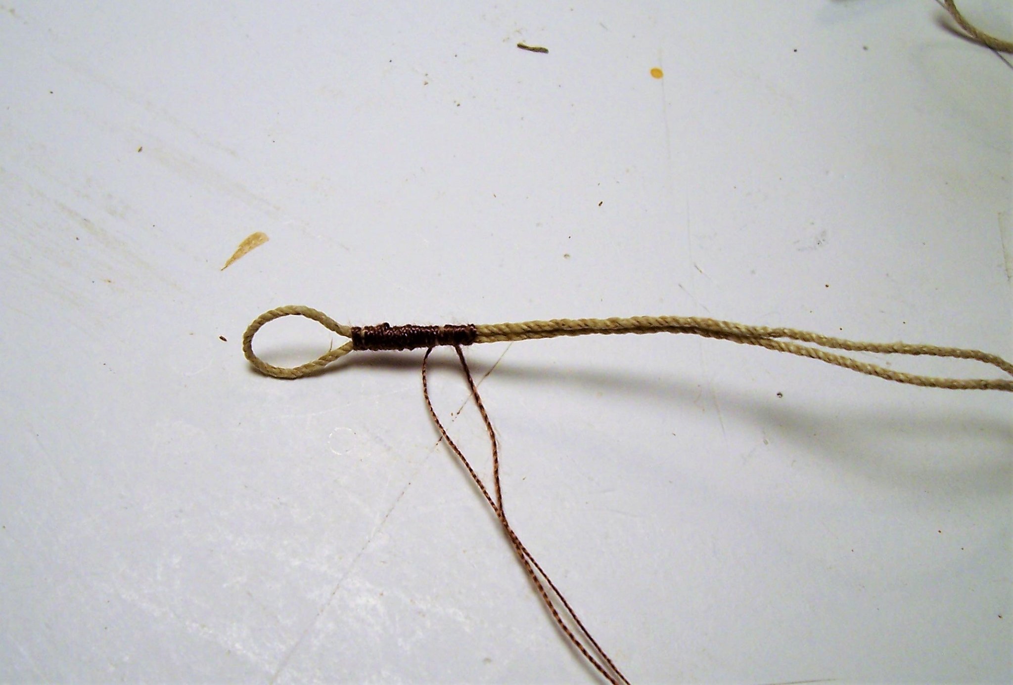
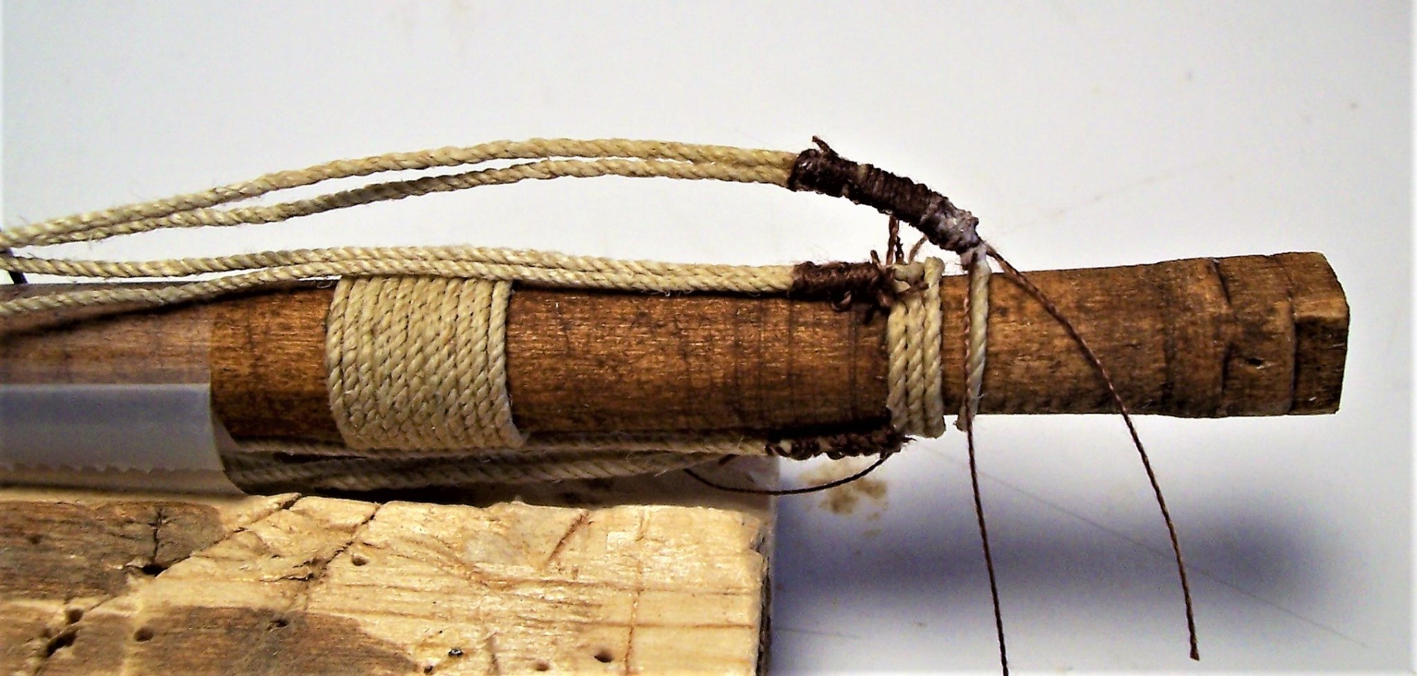
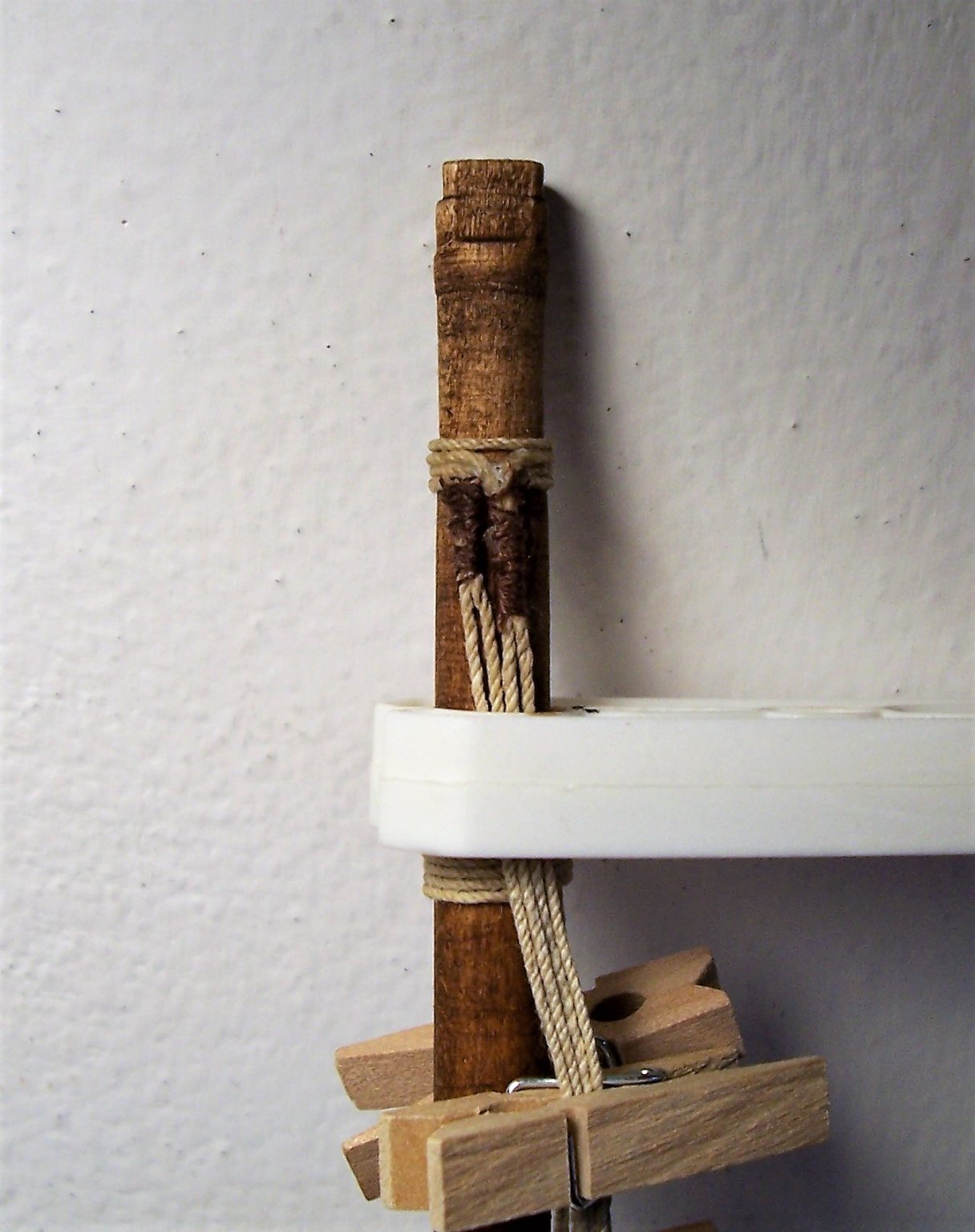
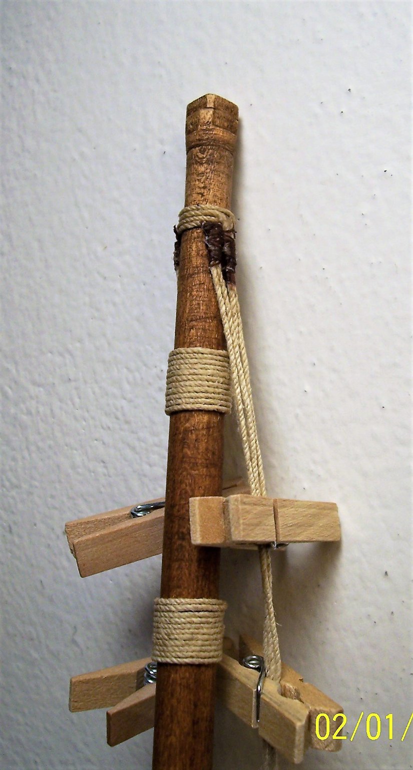
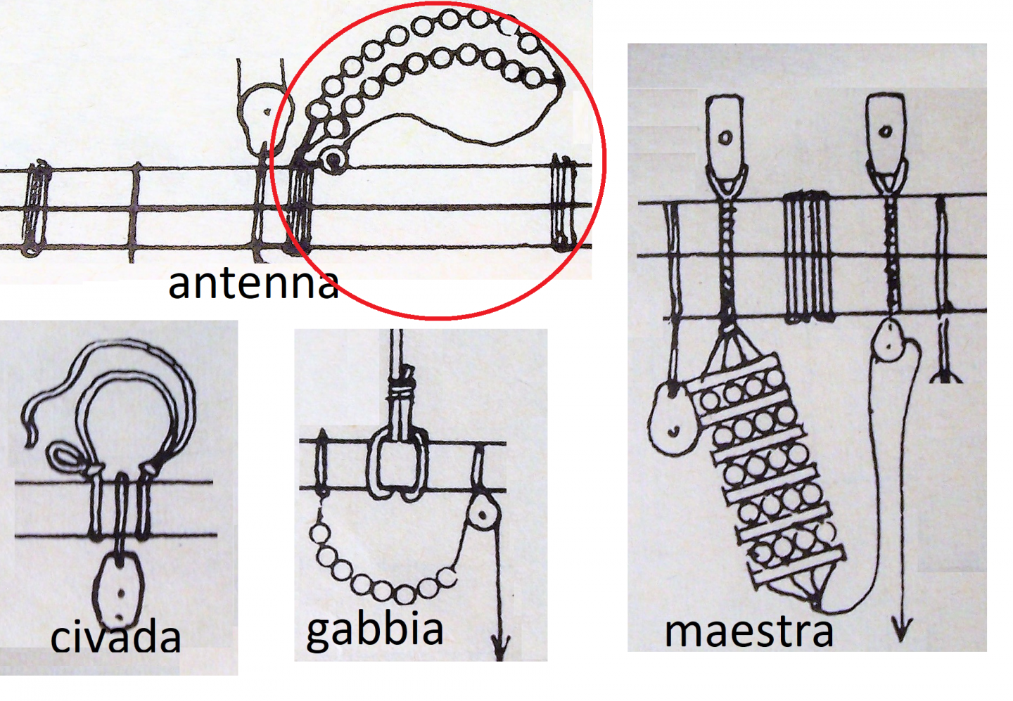
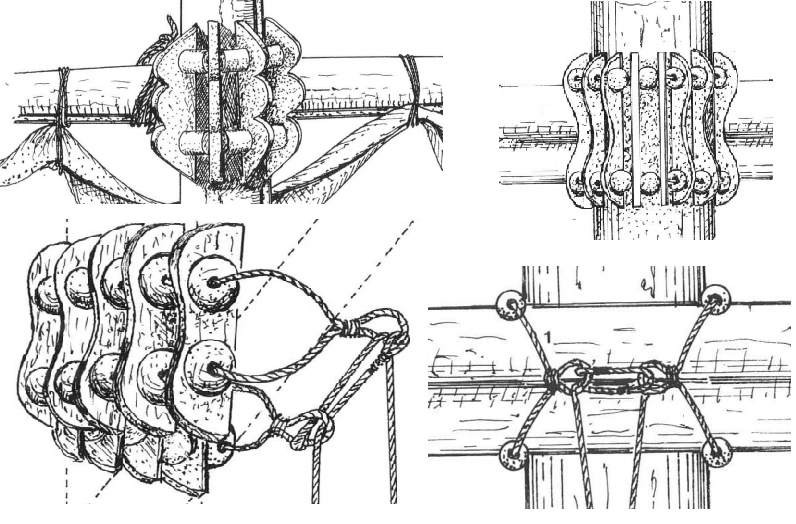
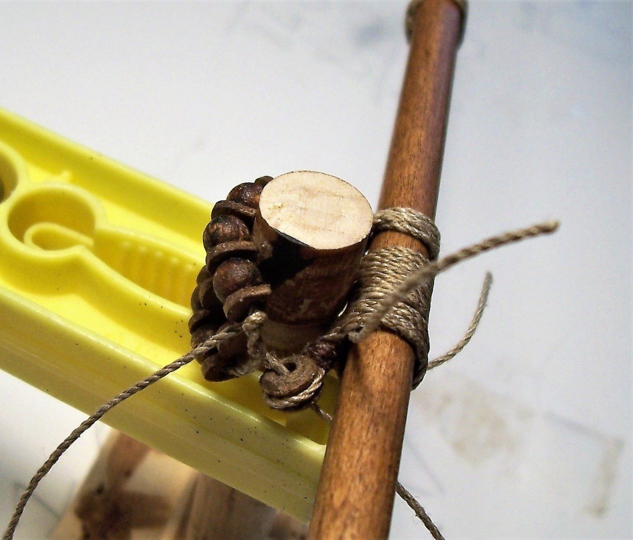
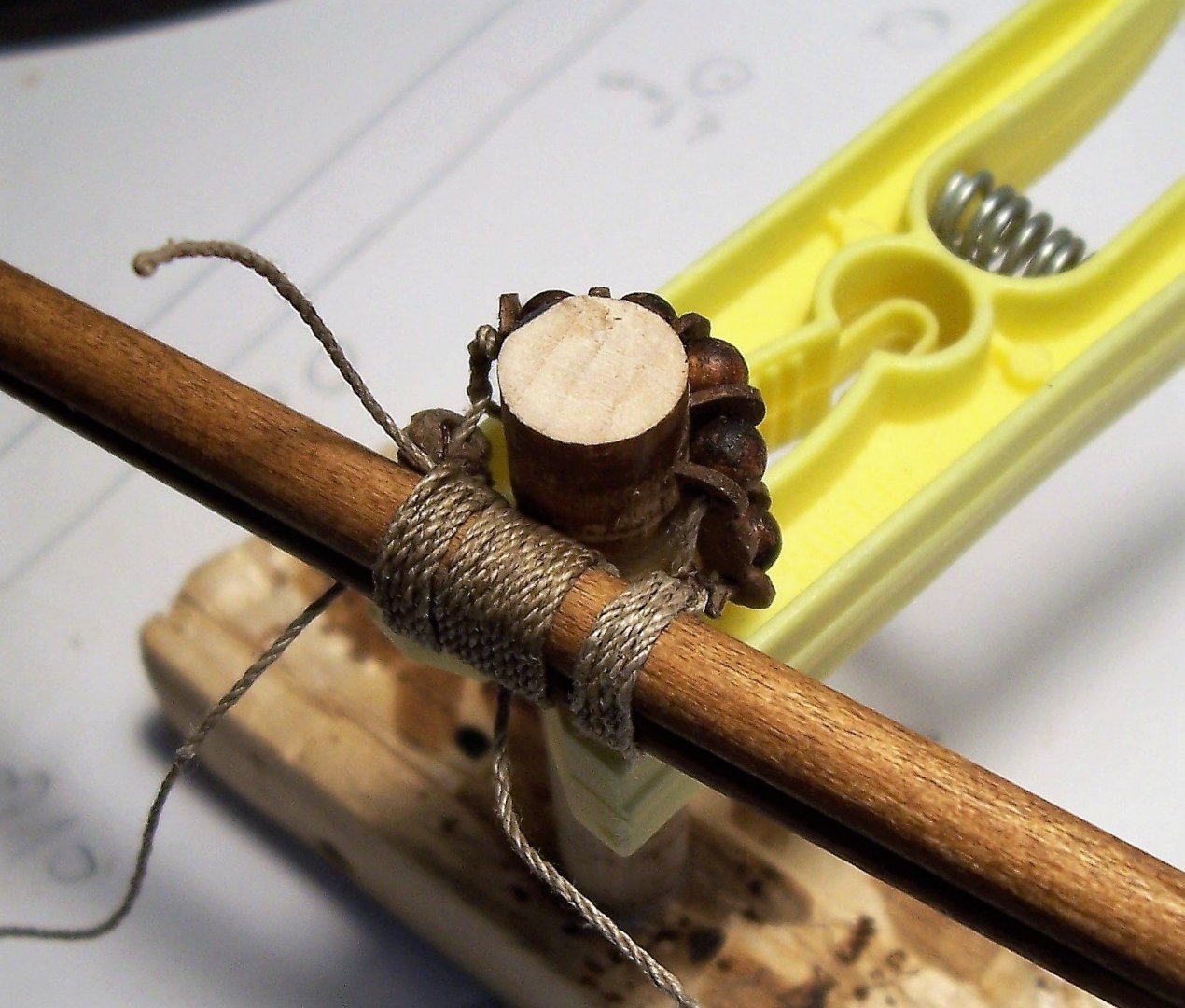
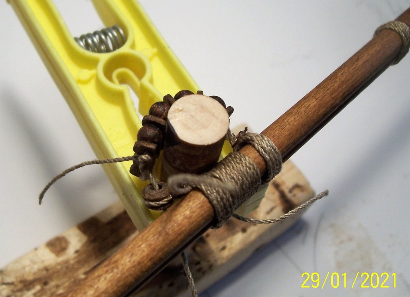
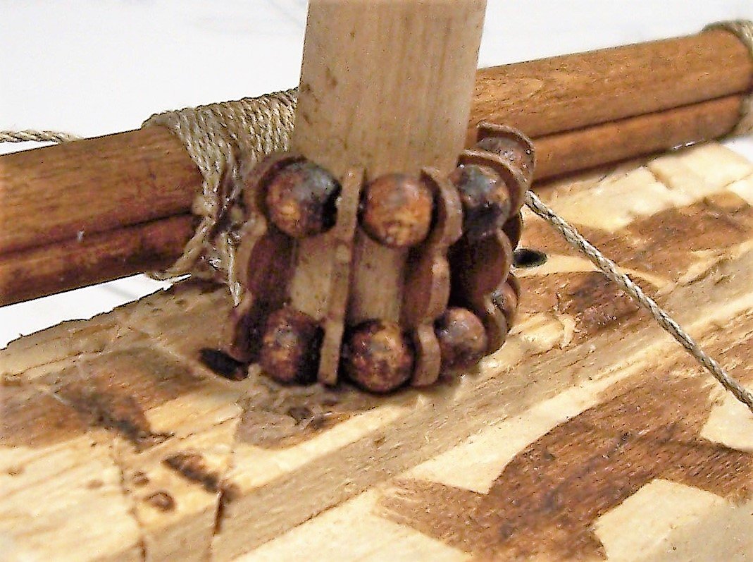
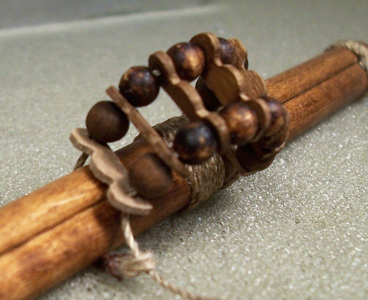
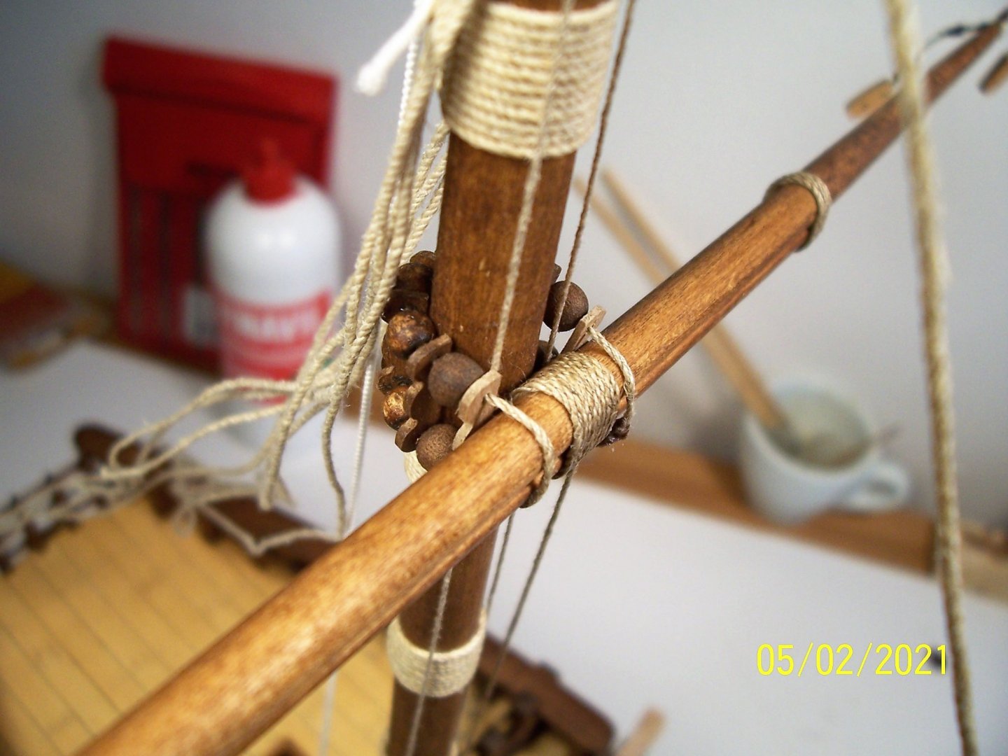
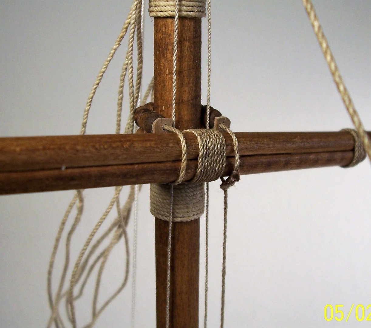
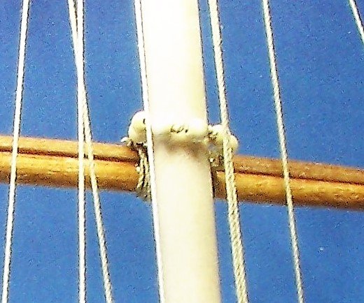
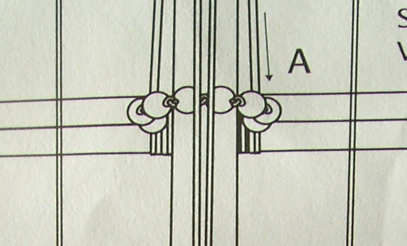
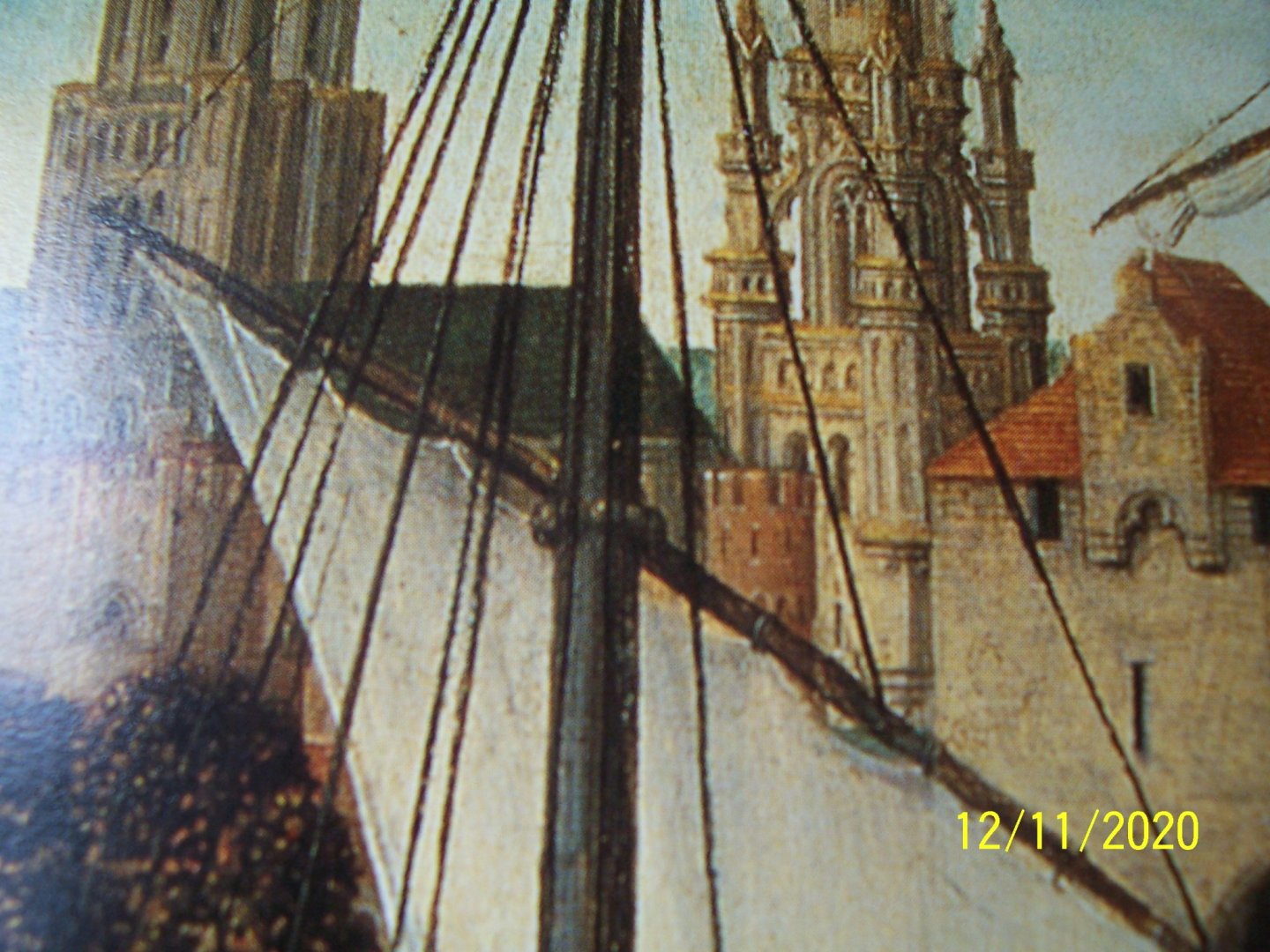
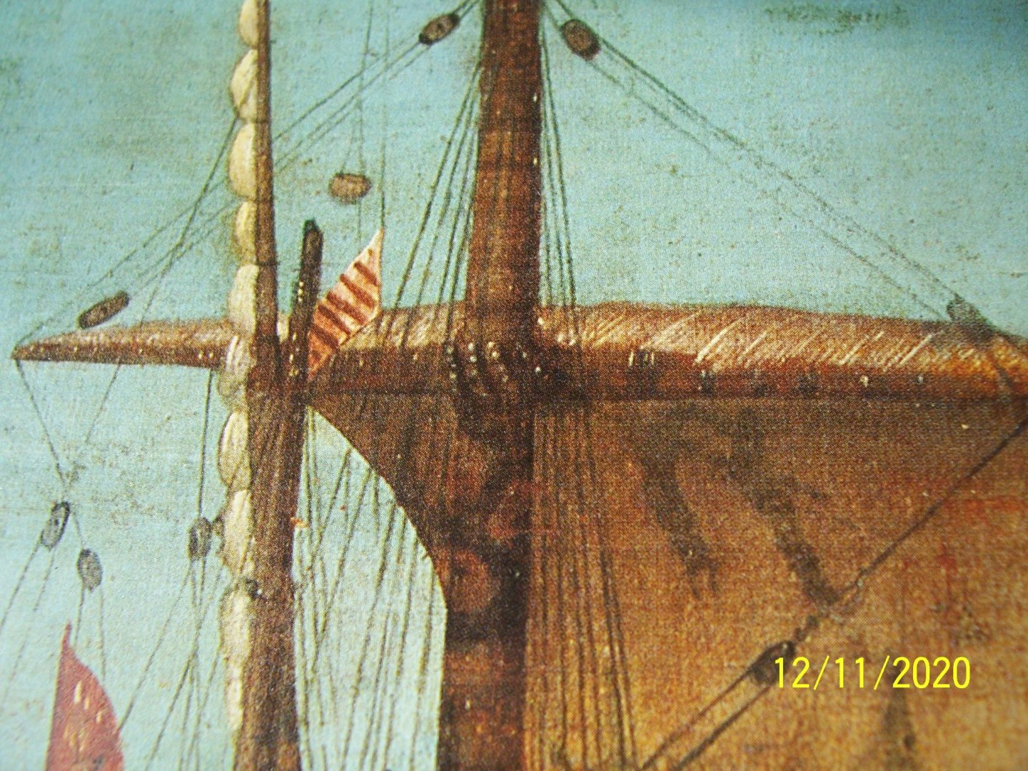
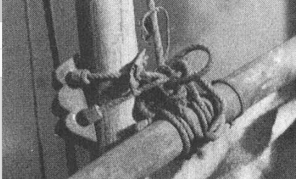
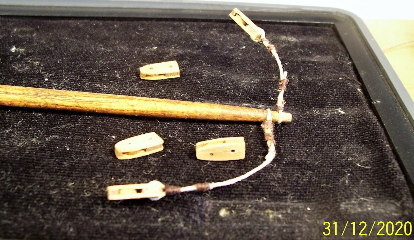
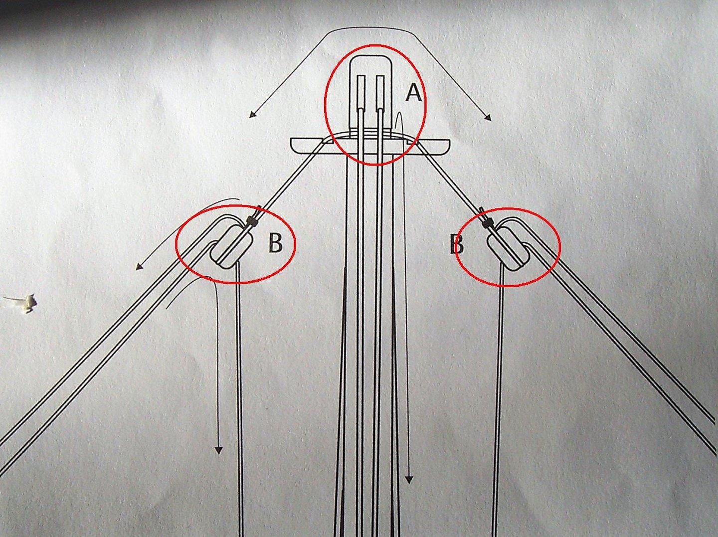
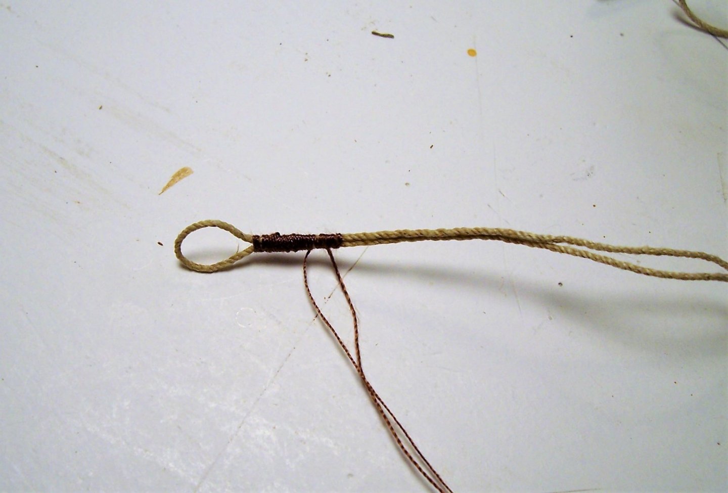
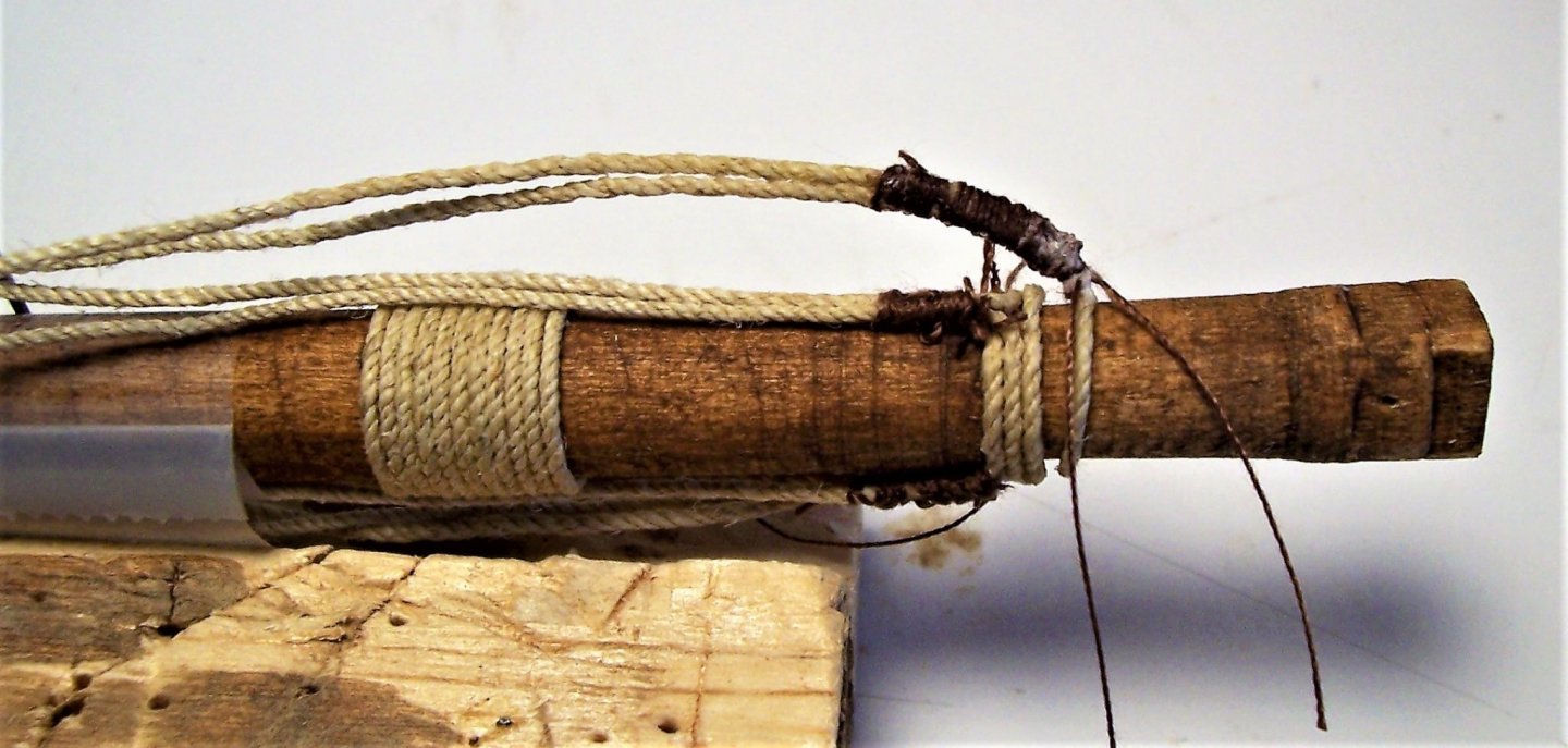
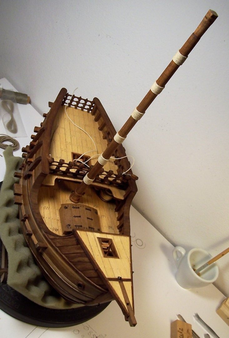
Dearest all, I have been looking for documentation about the fixing of the parrell in the fifteenth century. The most interesting books I've seen, they are: 1) Xavier Pastor - Anatomy Of The Ship- The Ships of-Christopher Columbus - CONWAY MARITIME PRESS 2) Heinrich Winter, Die Kolumbusschiffe (Magdeburg, 1944). The possibilities are numerous and I have collected them into two sets of drawings:, the first from Winter and the second from Pastor: As a first attempt, I tried the one circled in red: The result is not satisfactory, the parrel does not wrap around the mast well. After that, then I removed the wooden ring and replaced it with a double loop of rope, also adding ribs and trucks: In the pictures above, the parrel is only positioned but not yet fixed. The result seems acceptable to me. Now, the first thing to do will be to fix the halyard. See you again soon! Rodolfo


-
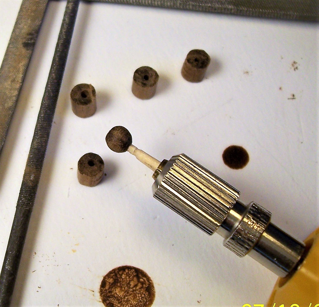
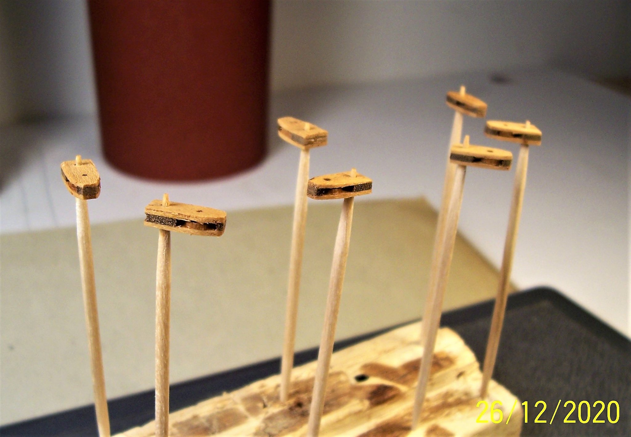
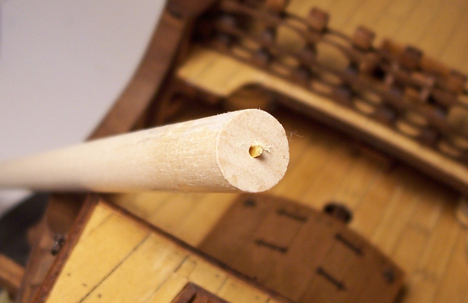
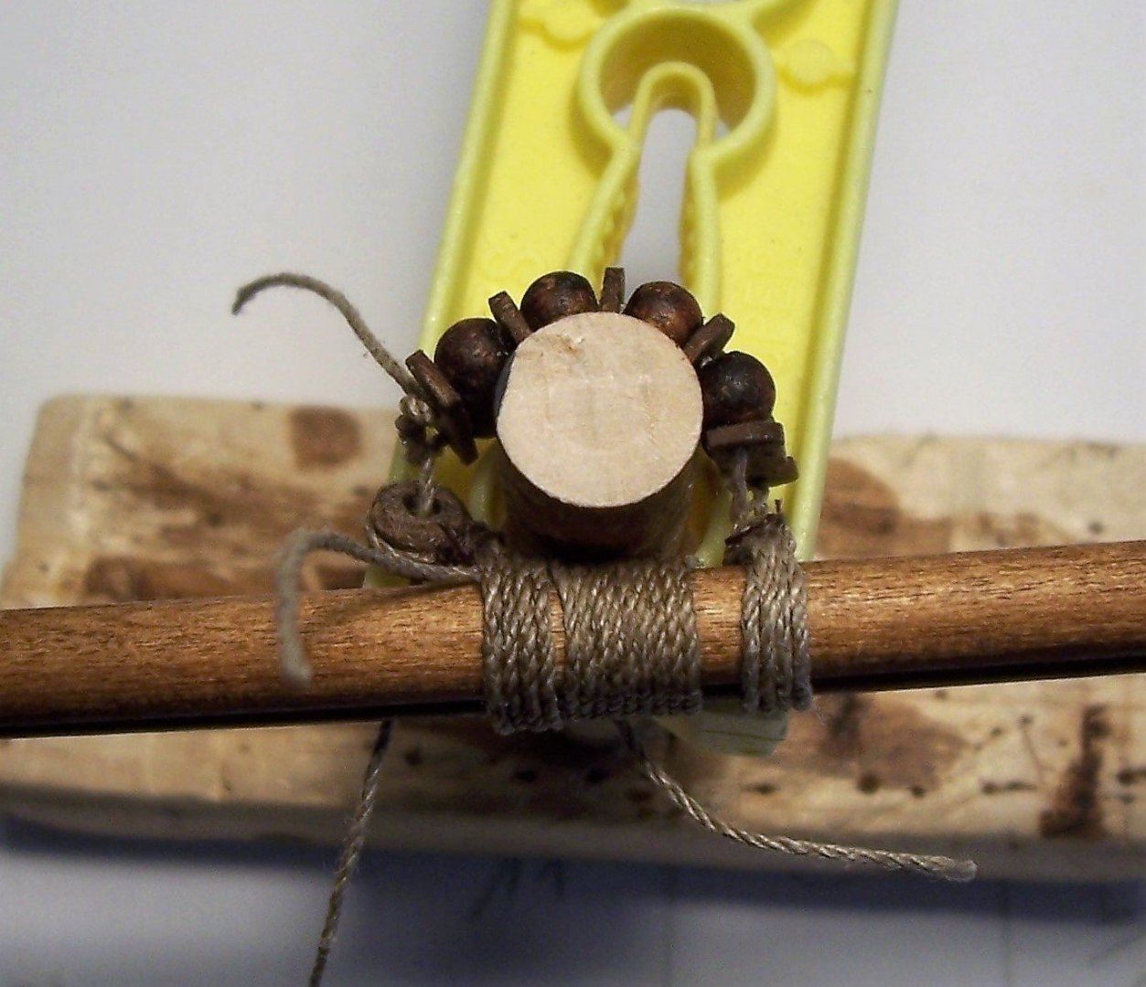
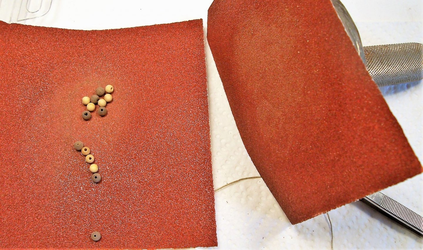
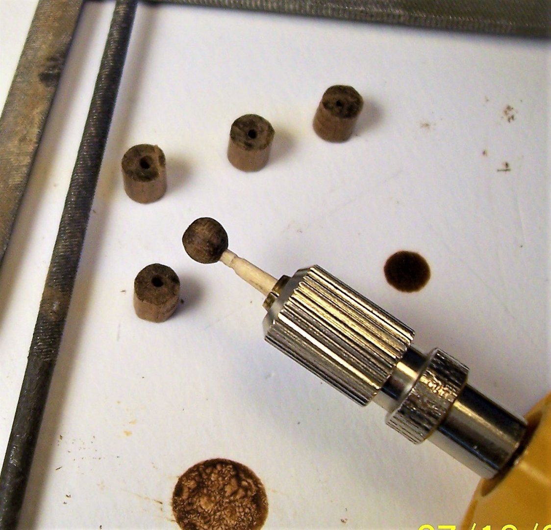
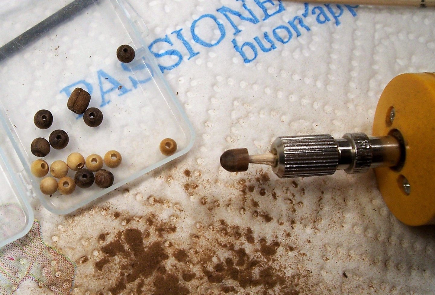
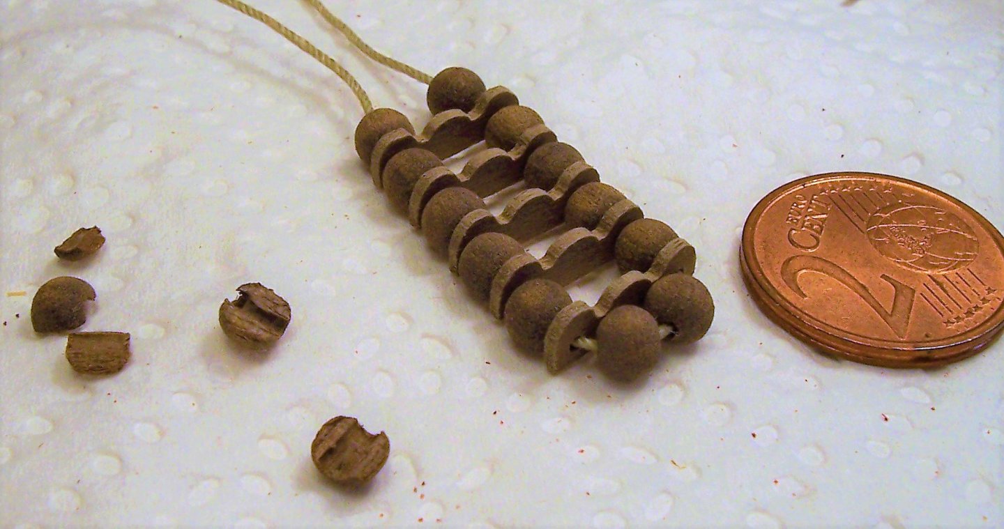
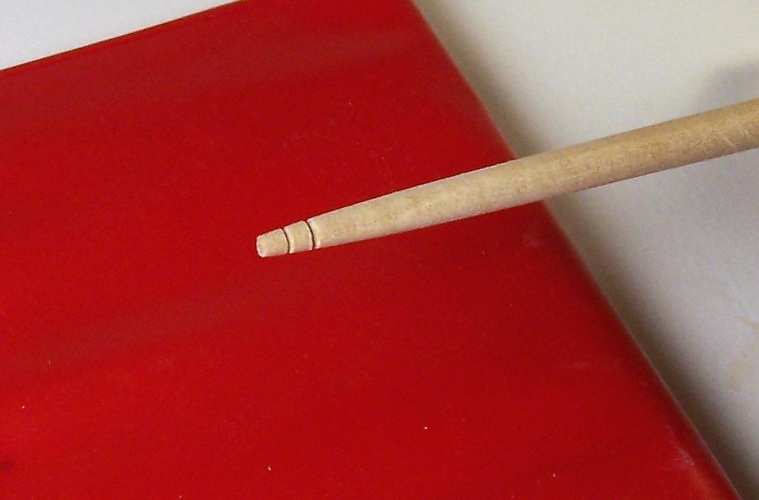
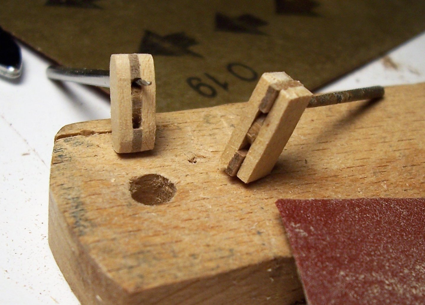
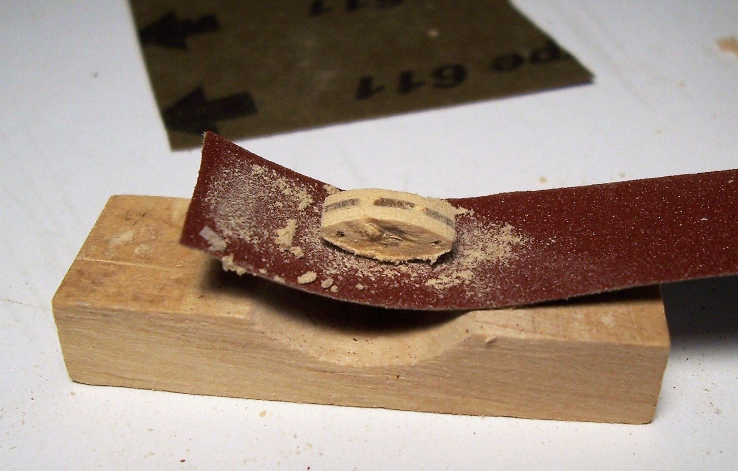
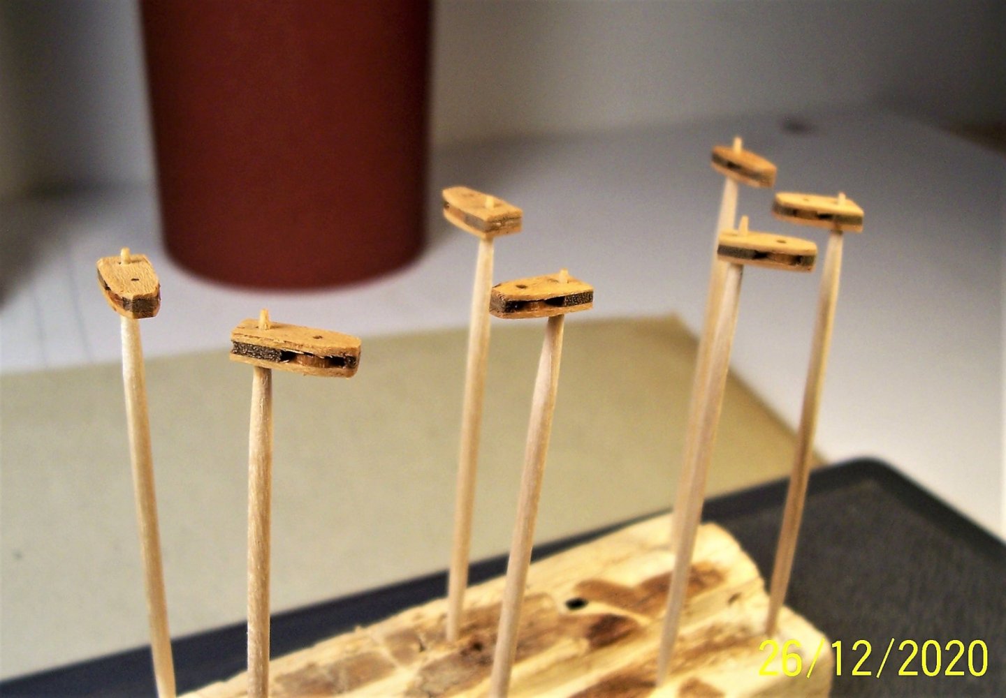
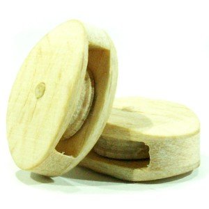
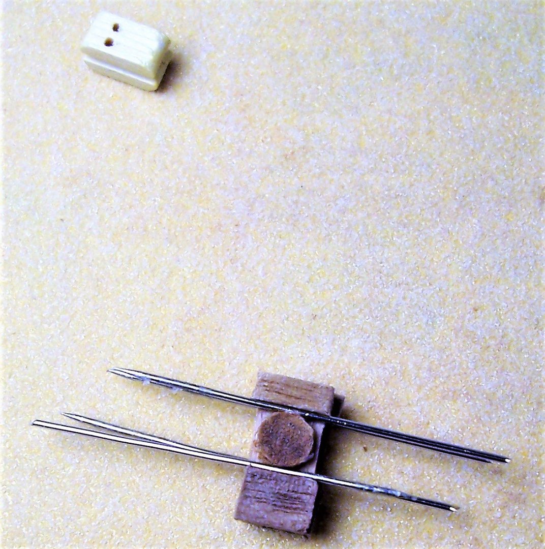
Dear Friends, to make the trucks I used a walnut rod drilled in the center 1.2 mm, then shaped with a file and sandpaper. Clear trucks are of AMATI:. Having everything necessary, we can try to build the parrel; here before painting: And now I'm going to tie it to the yard.... Have a nice weekend! Rodolfo
-
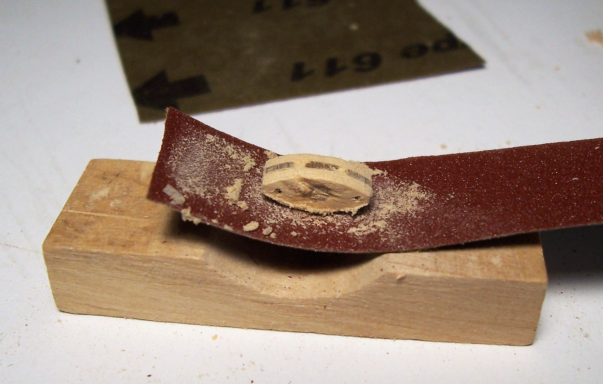
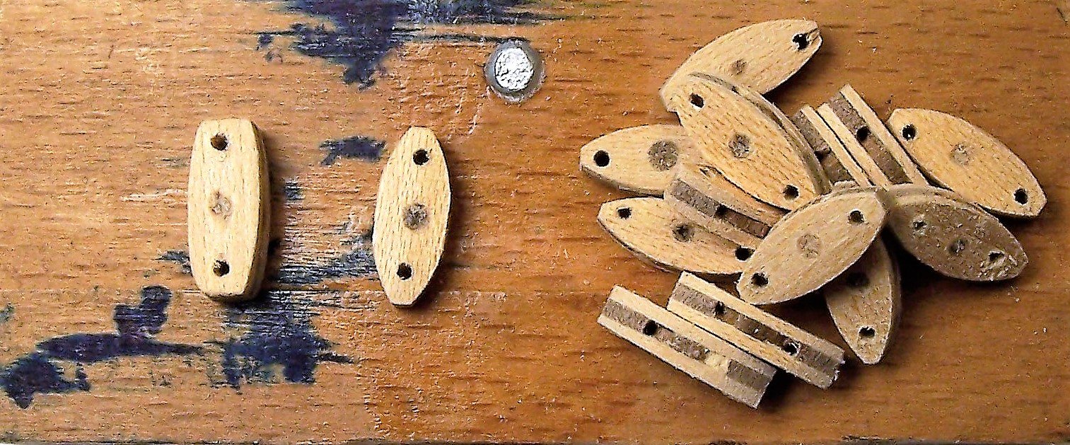
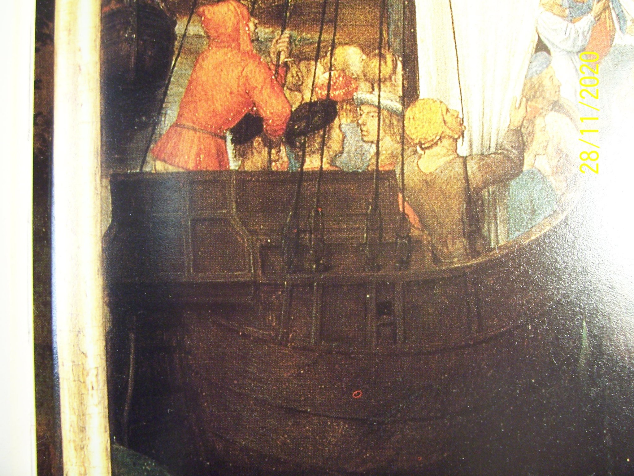
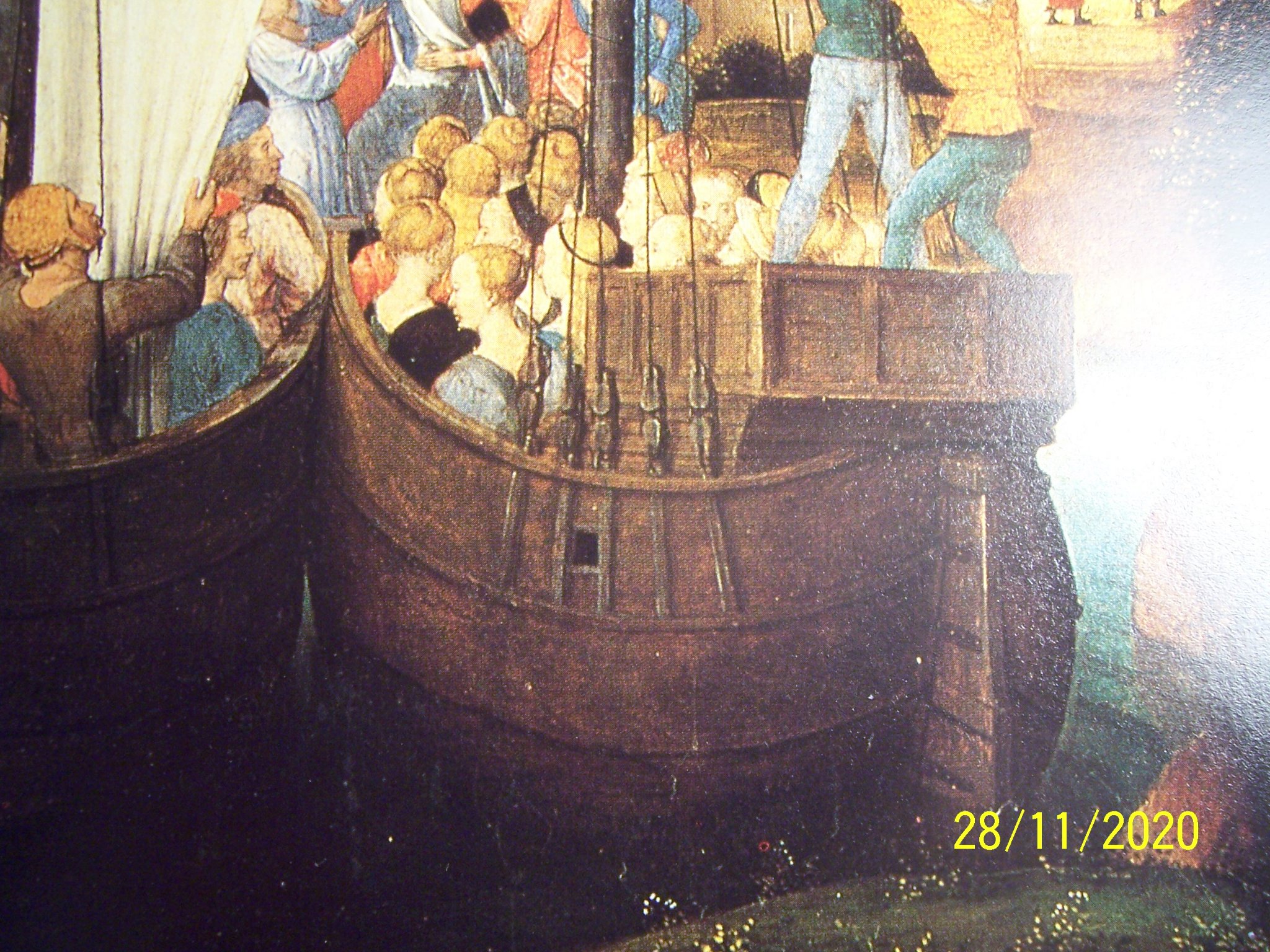
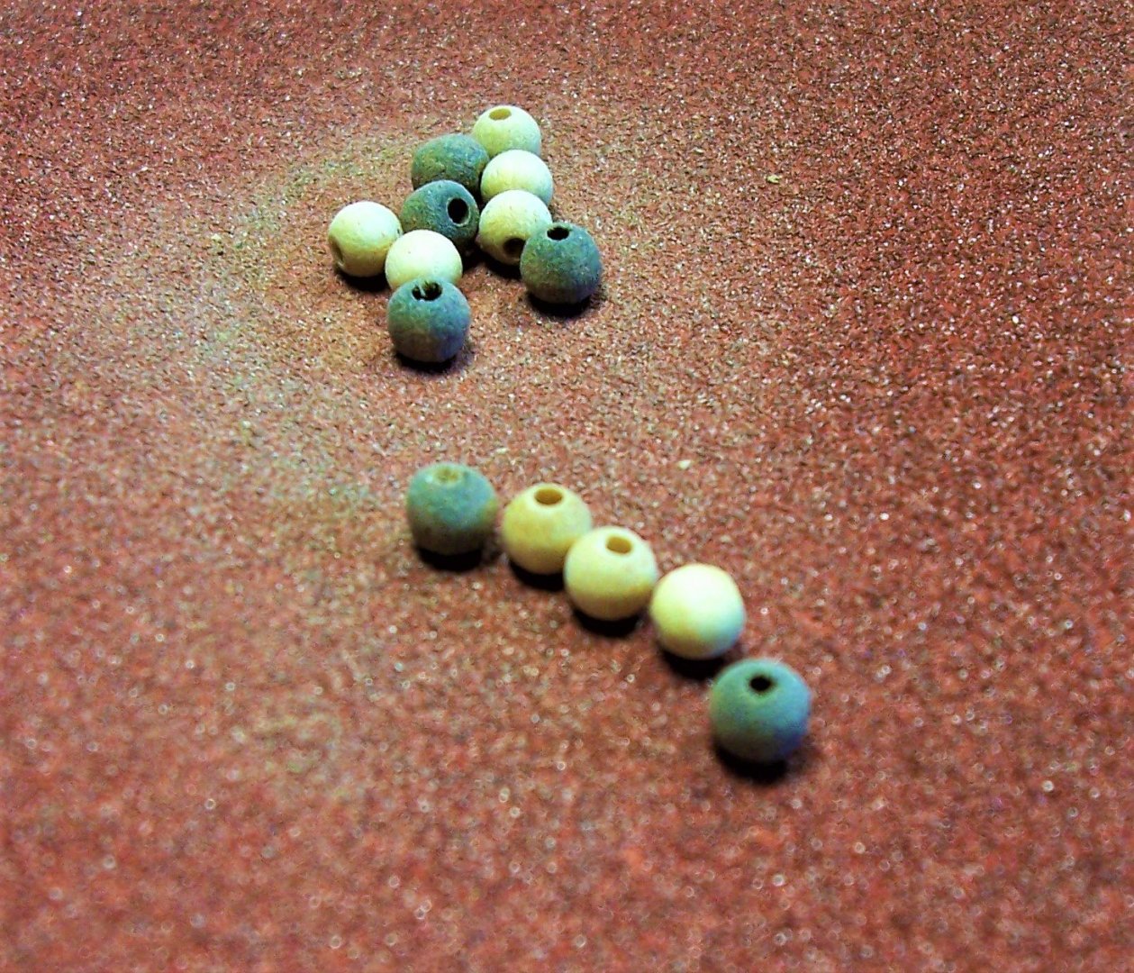
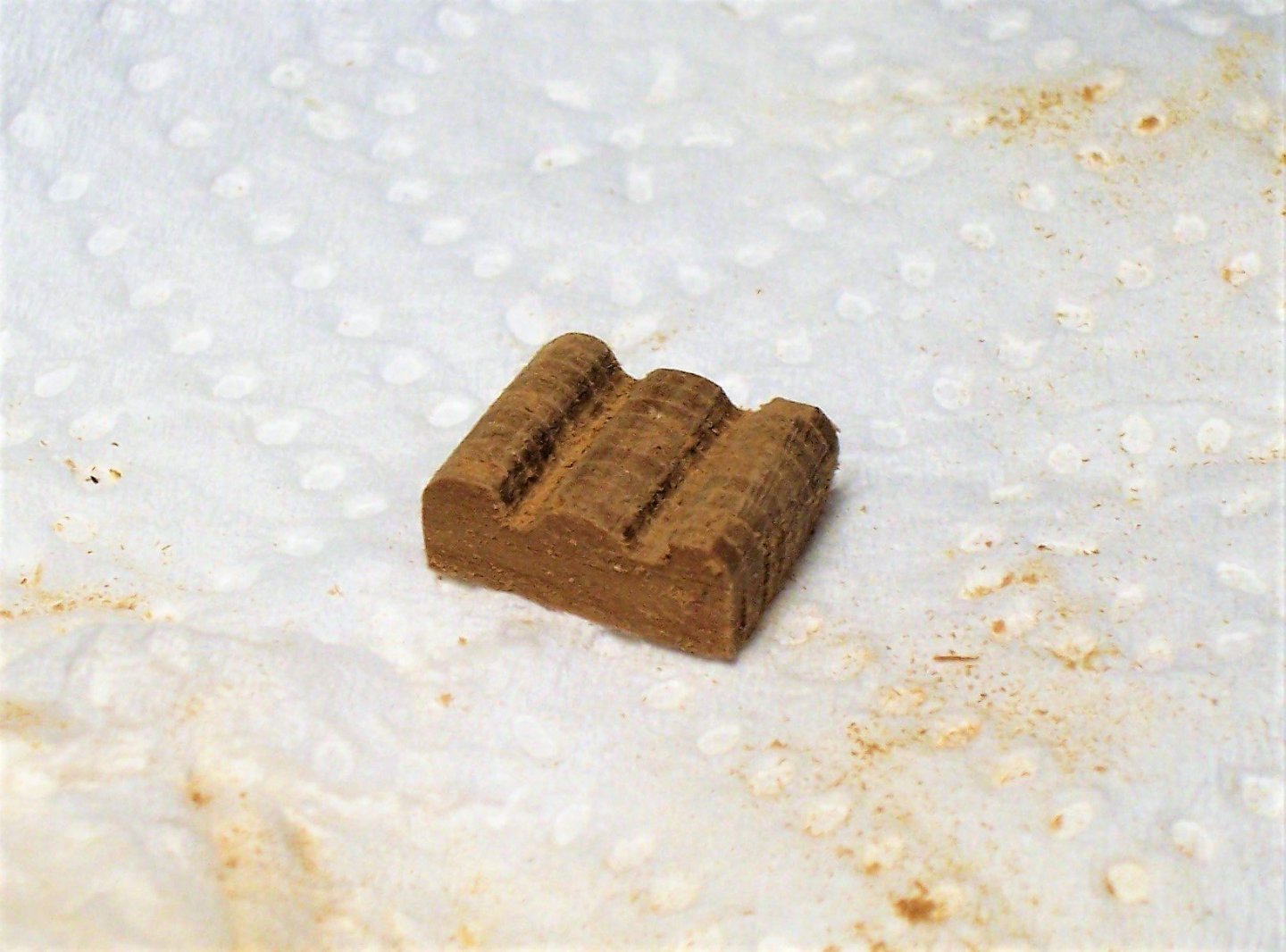
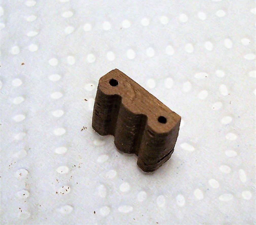
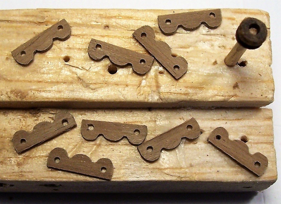
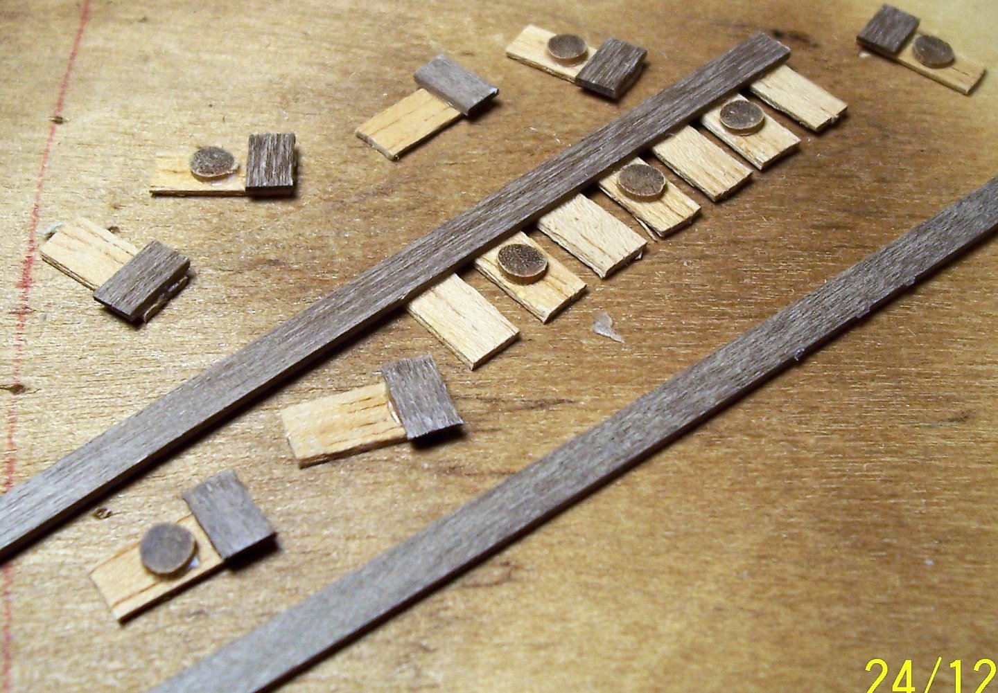
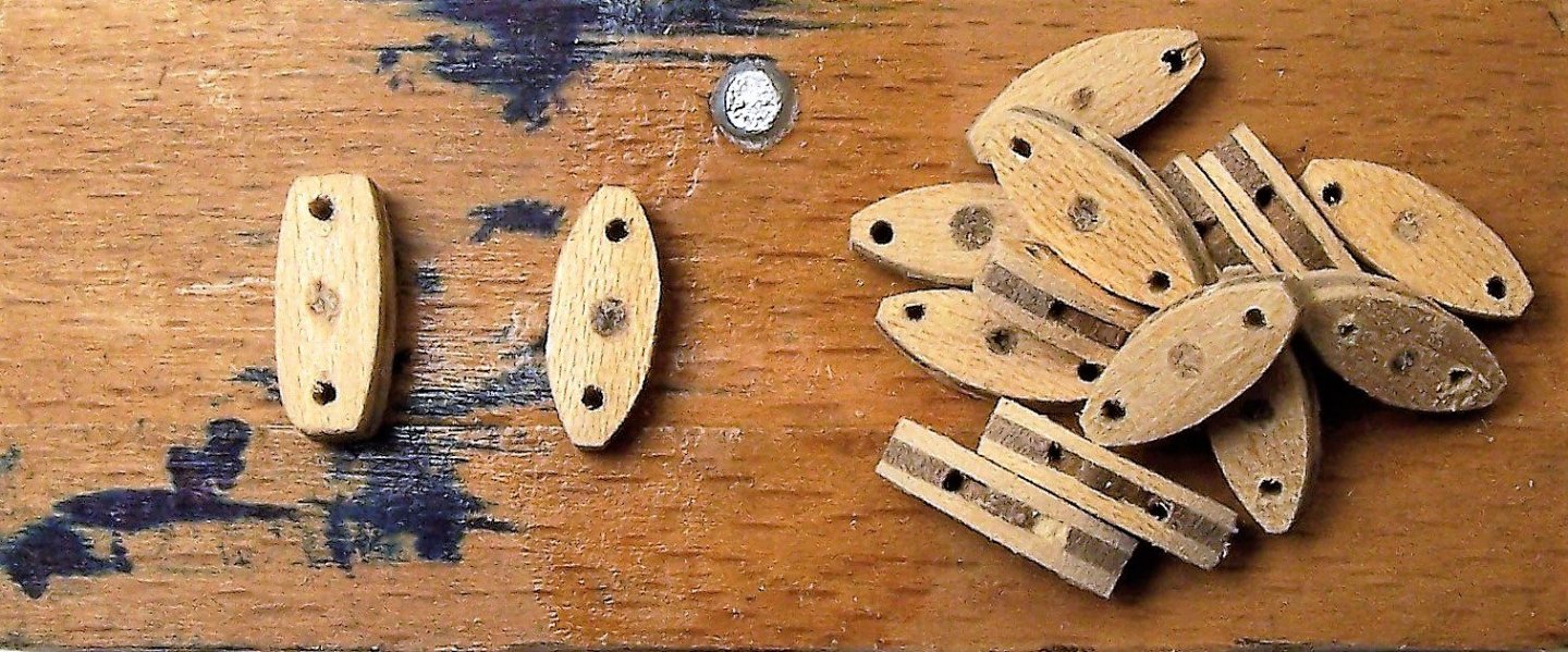
Dear All, to complete the yard it is necessary to prepare the parrel. The AMATI supplier solved the parrel problem simply with a row of spheres separated by knots. This solution is applicable, as demonstrated in this "Reliquary of St. Ursula" by Hans Memling dated pre-1489: However, it was probably only applicable to smaller ships because they are without a top. The larger ships had more rows of trucks, but the Nao of Mataro has only two rows: So the first step is building ribs and trucks. To make the ribs I glued a dozen pieces of a strip, shaped the block and drilled with a diameter of 1.2 mm; then I soaked the block in water and separated the individual ribs. Next step the trucks. See you again soon! Rodolfo

-
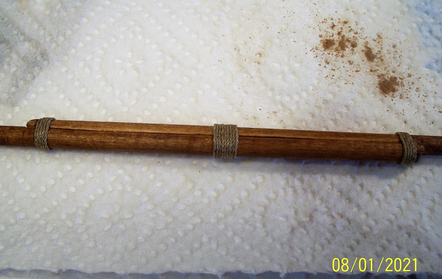
Welcome back to everyone! Work has continued with the construction of the yard, in two halves as can be seen from many illustrations of that time. The extremities are grooved for the fixing of the blocks. I've only followed instructions. Where the two halves overlap there are bindings. At the ends of the two halves, the first blocks, of the one-way type, were tied: At this point there will be the problem of the parrel.... See you soon! Rodolfo

-
Is it possible to see the keel and the frames free, not coupled ? May be it should be possible to evaluate the relative depth. Rodolfo
-
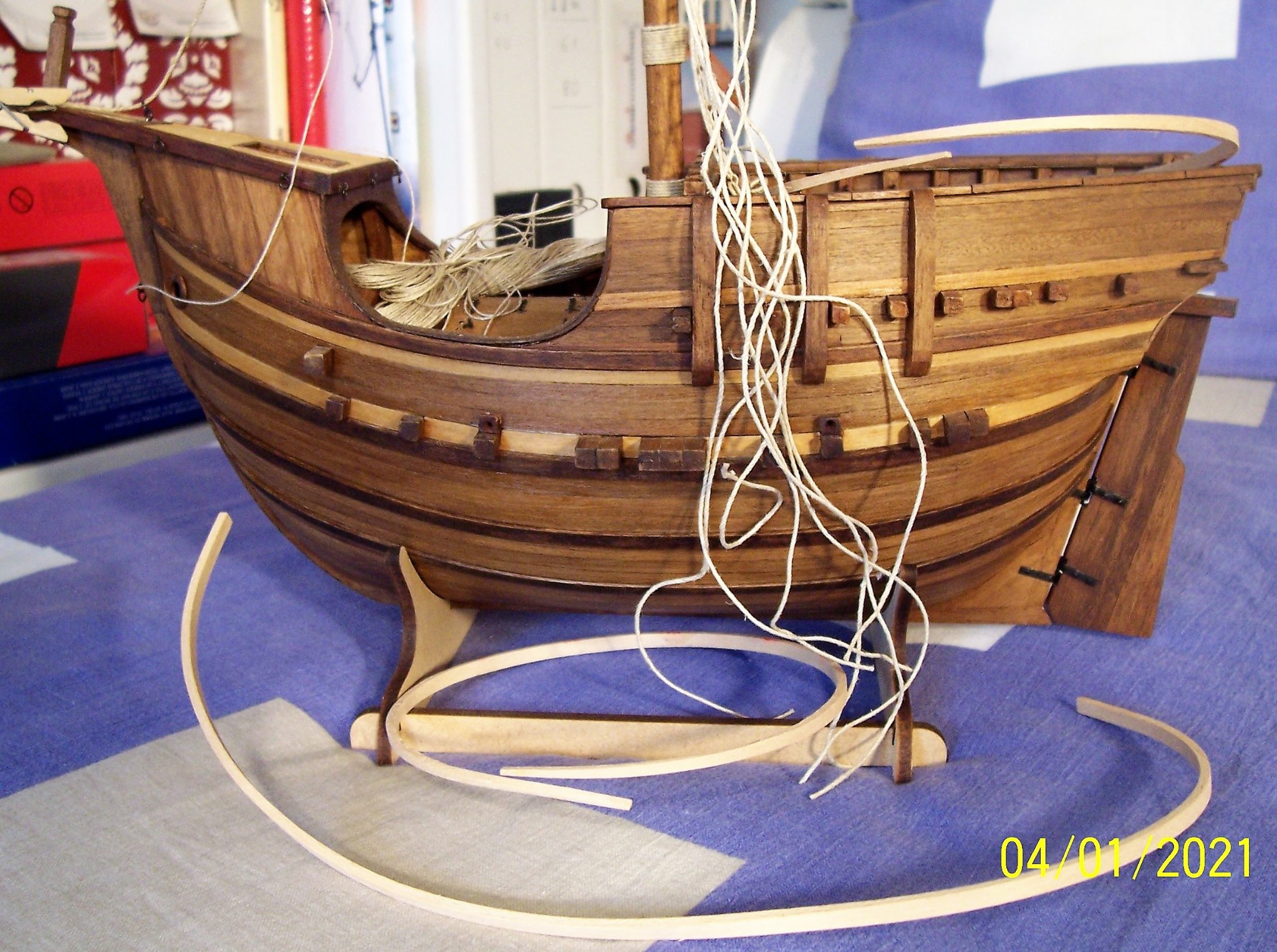
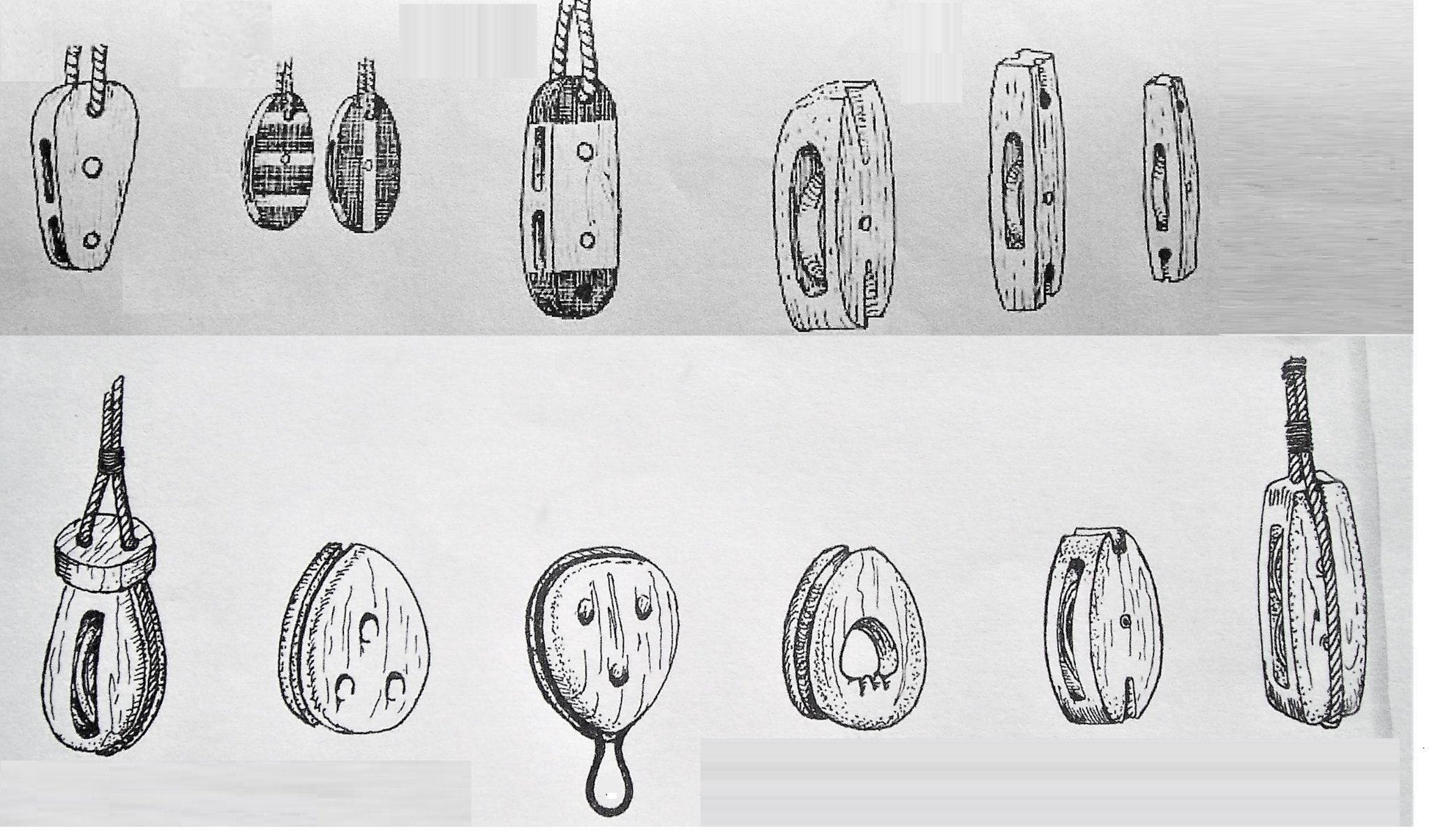
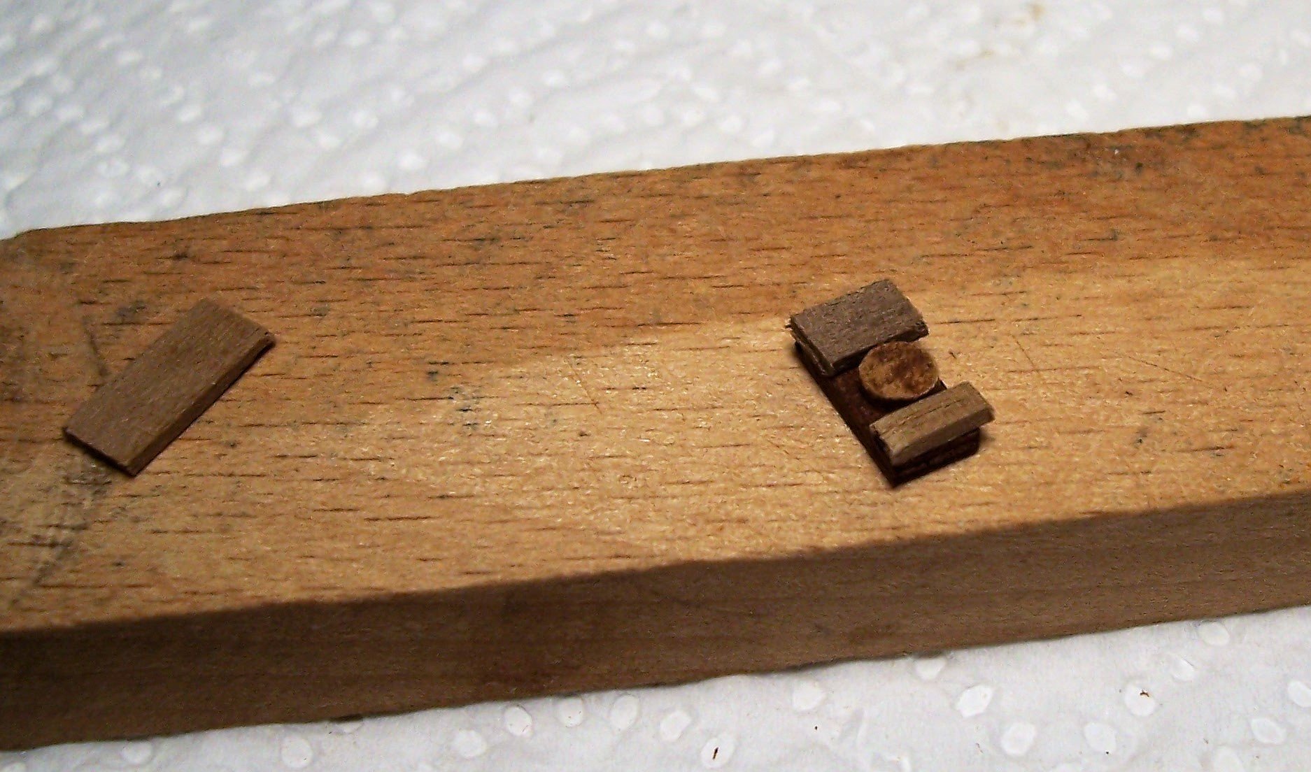
Hi Håkan, thank you for your positive comment. The round, belly shape of the hull made it tricky for me to lay the planking. In the end I got along fine by bending the planks (already tapered) in both directions. At the bow, the planking must rise more than at the stern. If the bending is more than necessary, the strip remains easily in its position, in contact with the keel. The 2X4 mm strips of basswood supplied by "AMATI" bend well, as shown by the photo of the leftovers after the first planking: Hi Steven, it seems to me that your solution is equally valid, because the pulley is always not visible ... By the way, over time I have collected in a sheet of Paint some various shapes of the blocks used in the ancient times. Perhaps it can be useful: See you soon and good sawdust to all! Rodolfo

-
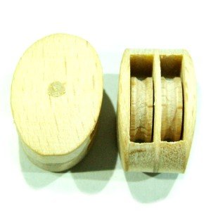
Thank Roger, for the encouragement. Hi Steven, I have only described the general order, but still on a theoretical level. I am now building the yardarm with the blocks, followed by the parrel (very different from that of AMATI), the blocks at the mast and the rope ladder. As soon as I have all the material ready, I will try to see the relative encumbrance in situ, before gluing. I mean, I'm still pretty much at high sea... About the sheaves they are glued. I'll glue also the rope inside the sheaves at the end of the work, because I prefer to avoid loosening during the course of time. But if you prefer, I think it should be possible make them swiveling by drilling a hole in the wooden disc and inserting a pin or wire of a suitable diameter. Maybe also need to make the inside walls of the block very smooth, with fine sandpaper, if you want to make the rigging often movable. See you soon! Rodolfo
-
Thanks Steven for your very helpful remarks and documents. I will undoubtedly take them into account for the prosecution: surely the mast crosstree will be planar. About the yard, although it was never intended to be hauled all the way to the top, with the block so low: I suppose it could reach maybe halfway up the mast. It is necessary a greater distance between block and rack. I have enough in mind how to proceed in order to have less obstacles and obstructions as possible: first the stay, then the installation of the yard with blocks and parrel, then the crosstree followed by the rope ladder, the two blocks on the mast for the yard and finally the side shrouds (Only the fixing at the bulwarks, because they are already tied at the top). It will really be a Work in Progress, evaluating step by step how to proceed. The problem about quality of the blocks can be solved by DIY; at least two different kinds. In the Nao of Mataro there are even more... In the meantime I've tied the first blocks to the yardarm. How useful it would be to have small hands ... I would like to conclude by wishing everyone a Happy New Year, even if the signs are not very good, unfortunately. Rodolfo
-
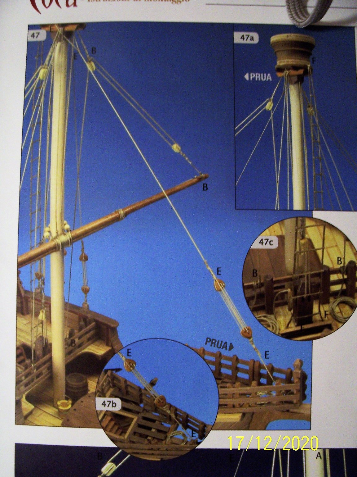
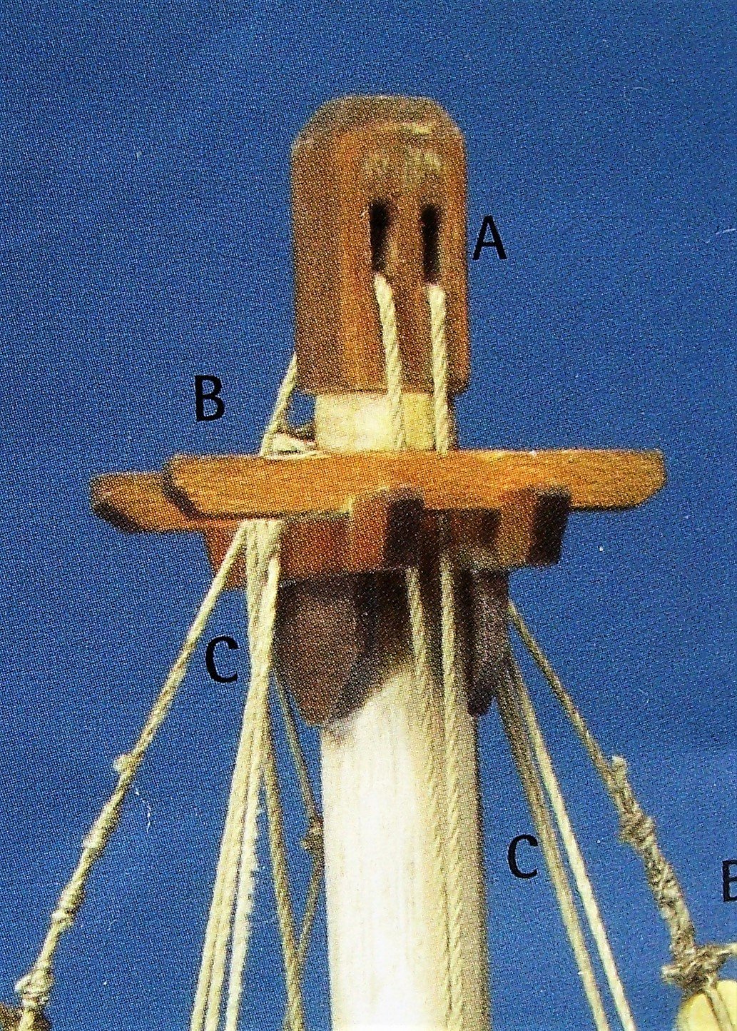
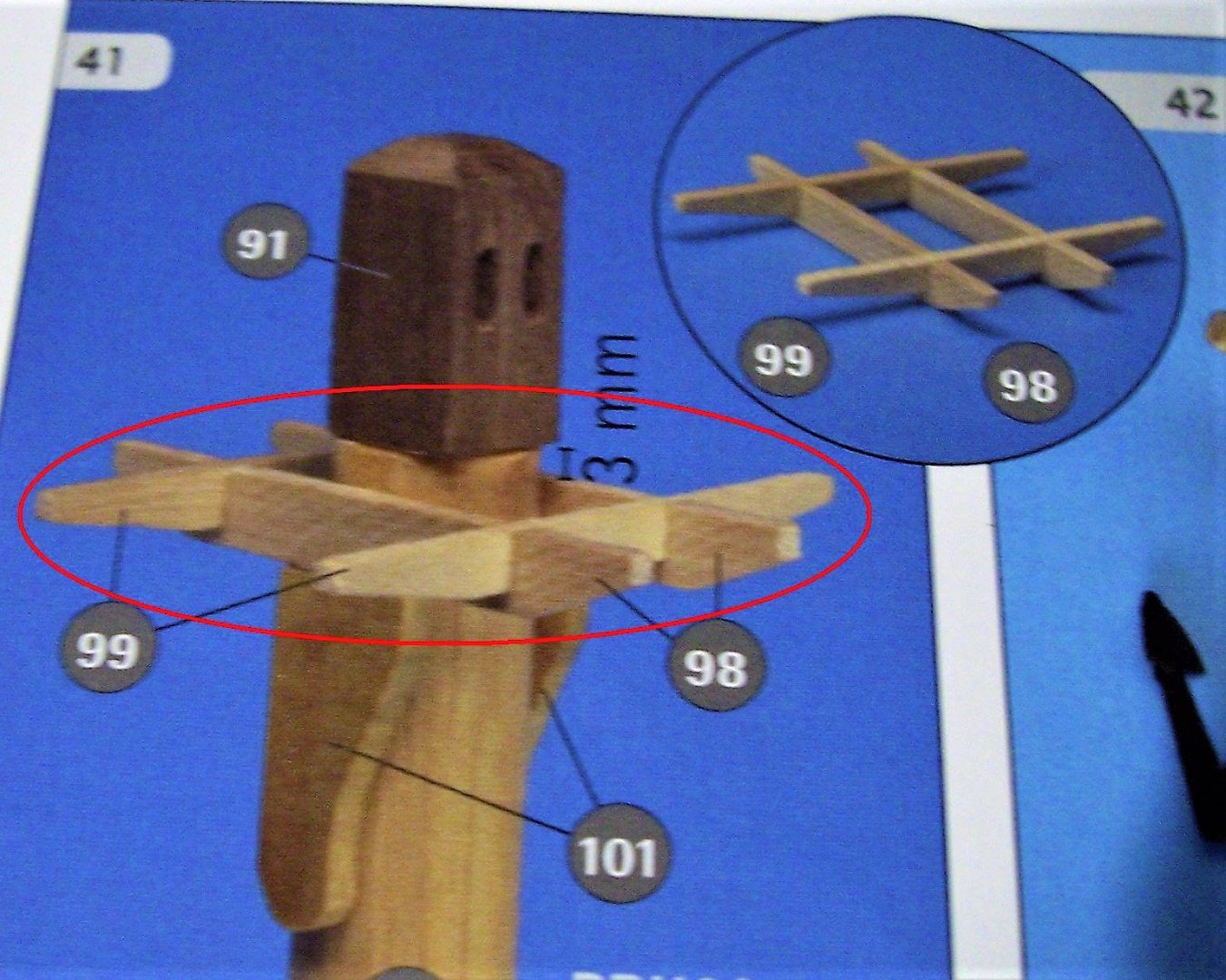
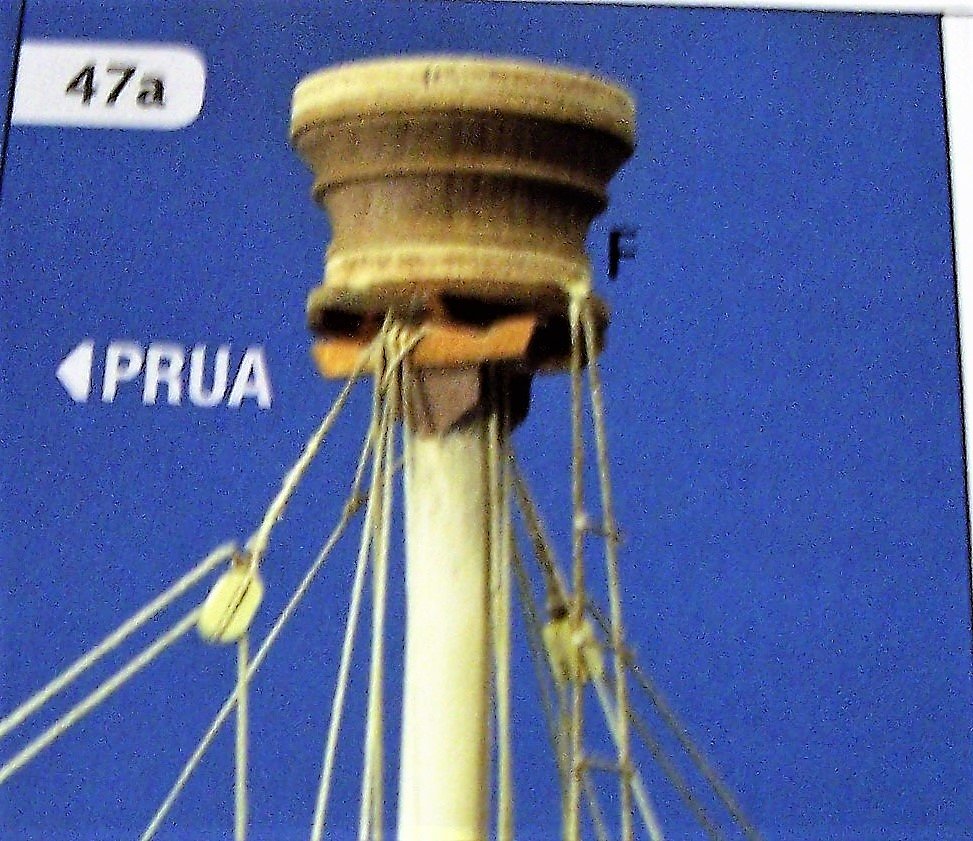
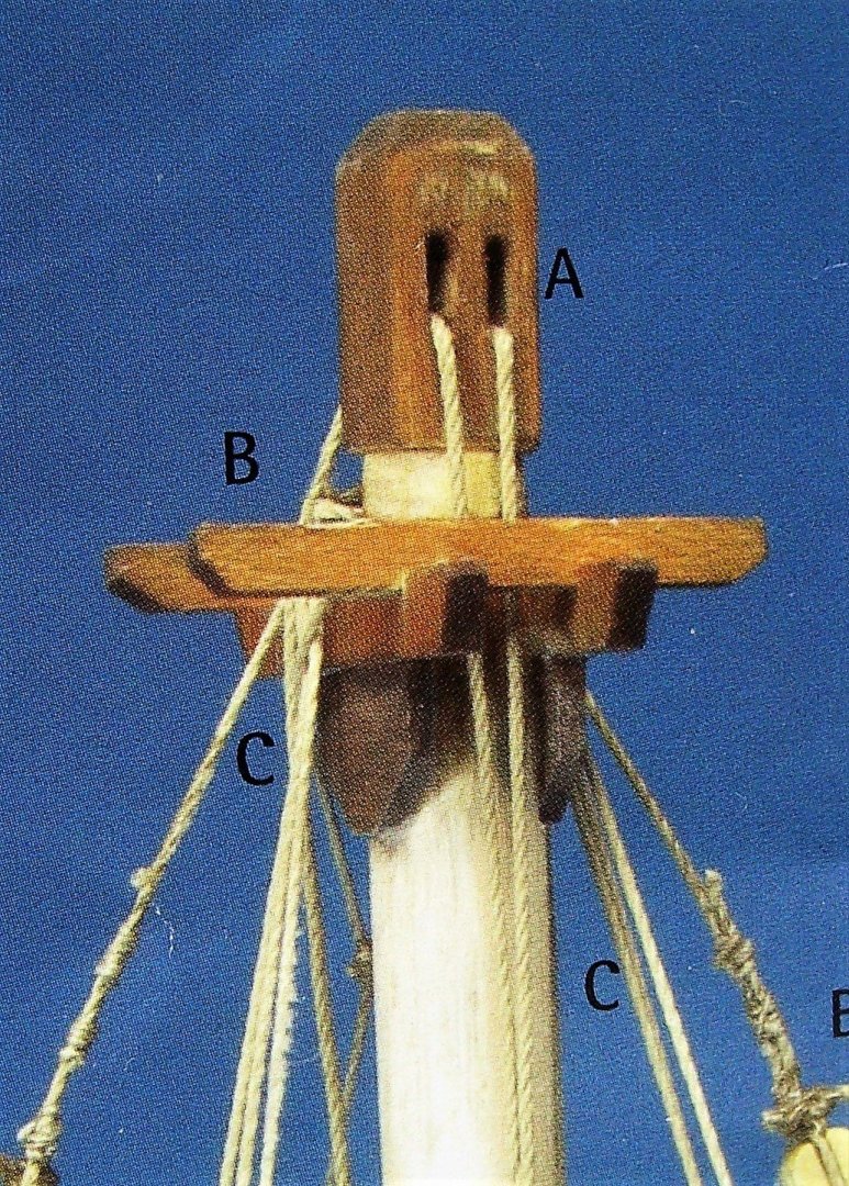
Greetings everybody! In this post I want to list some problematic aspects of the instructions, regarding next steps of the construction. THE MAST CROSSTREE: pictures give two contrasting views: in the first one it's almost flat, in the second one and in the drawing the trestletrees are at a different level from the transoms: This affects the positioning of the blocks, the stay and the rope ladder. THE PLACEMENT OF THE BLOCKS: from the drawing it seems that the current cable does not run along the sheave, as if the block were placed upside down: THE HALYARD: Based on the drawing, it would not seem possible to raise the yard to the top, as the block is too close to the rack: As I plan to put the yard at the bottom, I will have to put the block much higher. THE ROPE LADDER: it's not clear how it ends up: it seems nailed to the base of the mast top (point F), in a way that seems impossible to go inside: Anyway, all these problems can be solved with a bit of work and patience.... Have a nice evening everyone! Rodolfo


-
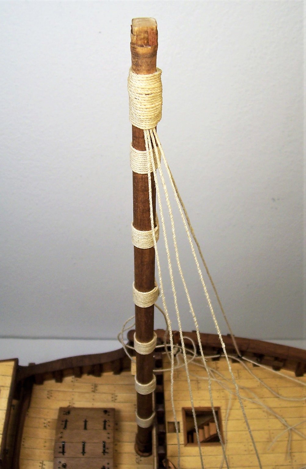
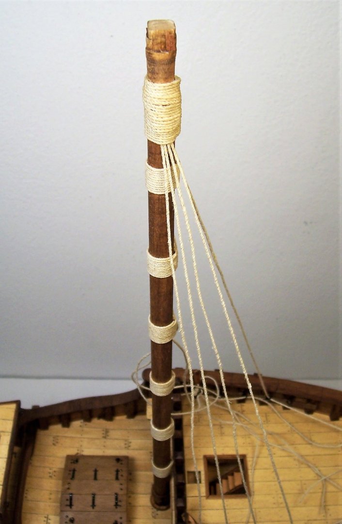
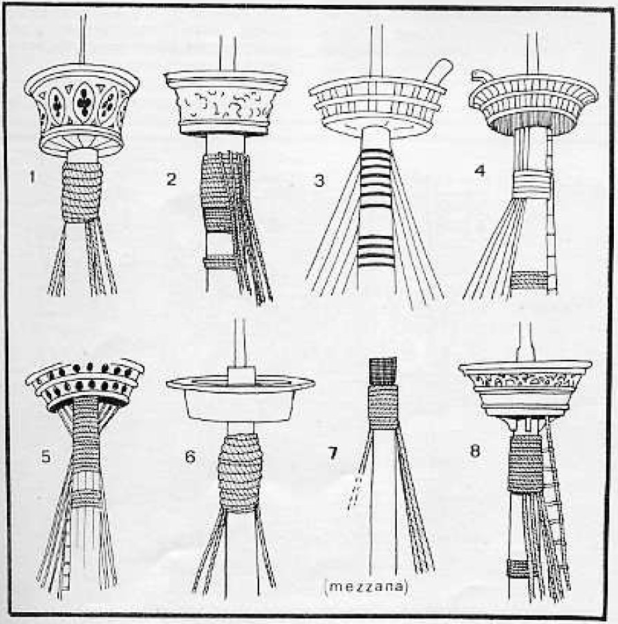
Merry Christmas to all the friends of the forum! The work has continued with rigging of the shrouds, according to fig.8 among the typical arrangements of that time, previously illustrated by Pino dall'Orco in "Sartie, stile mediterraneo": I made four pairs of shrouds, alternating them at the top and then wrapping the whole with rope: Next steps will be quite problematic: regarding the crosstree, there are some incongruences between drawings and figures in the instructions. Moreover we must consider that we've to place the stay, the rope ladder running from quarterdeck till to the top, the halyard and the ties for the blocks of main mast lift. And with all these things we need to leave a free passage for one person from the ladder inside the top. We'll see what can be done. Have a nice evening, Rodolfo


-
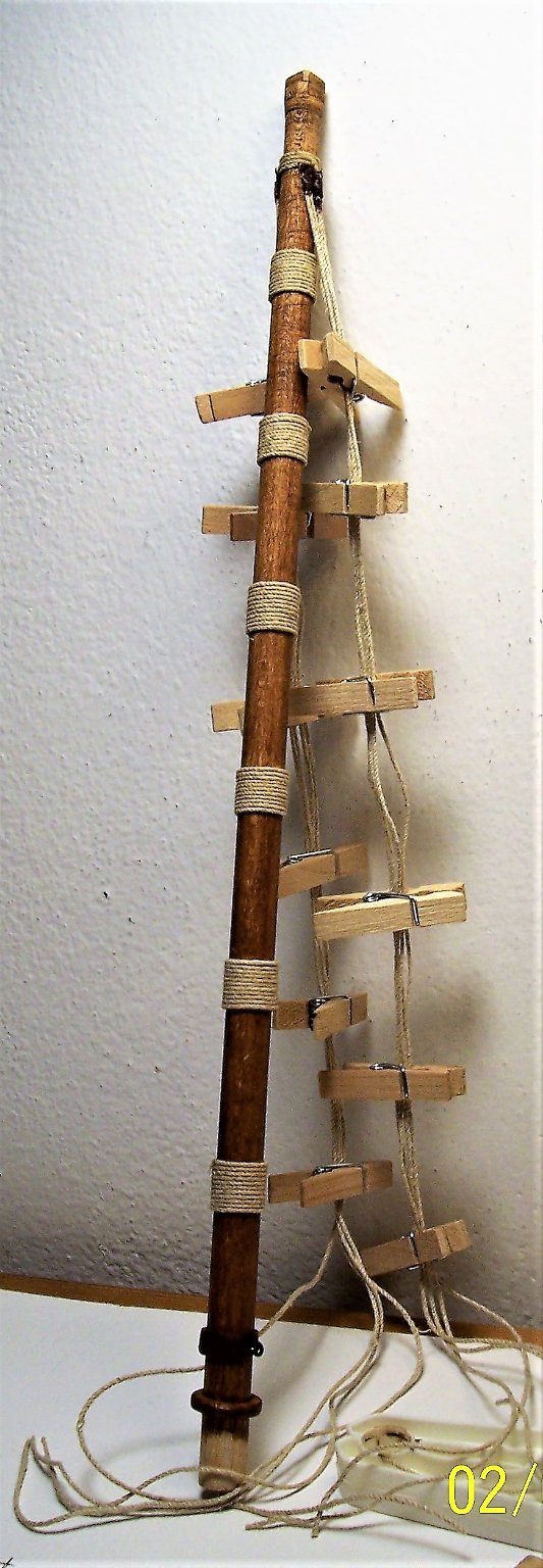
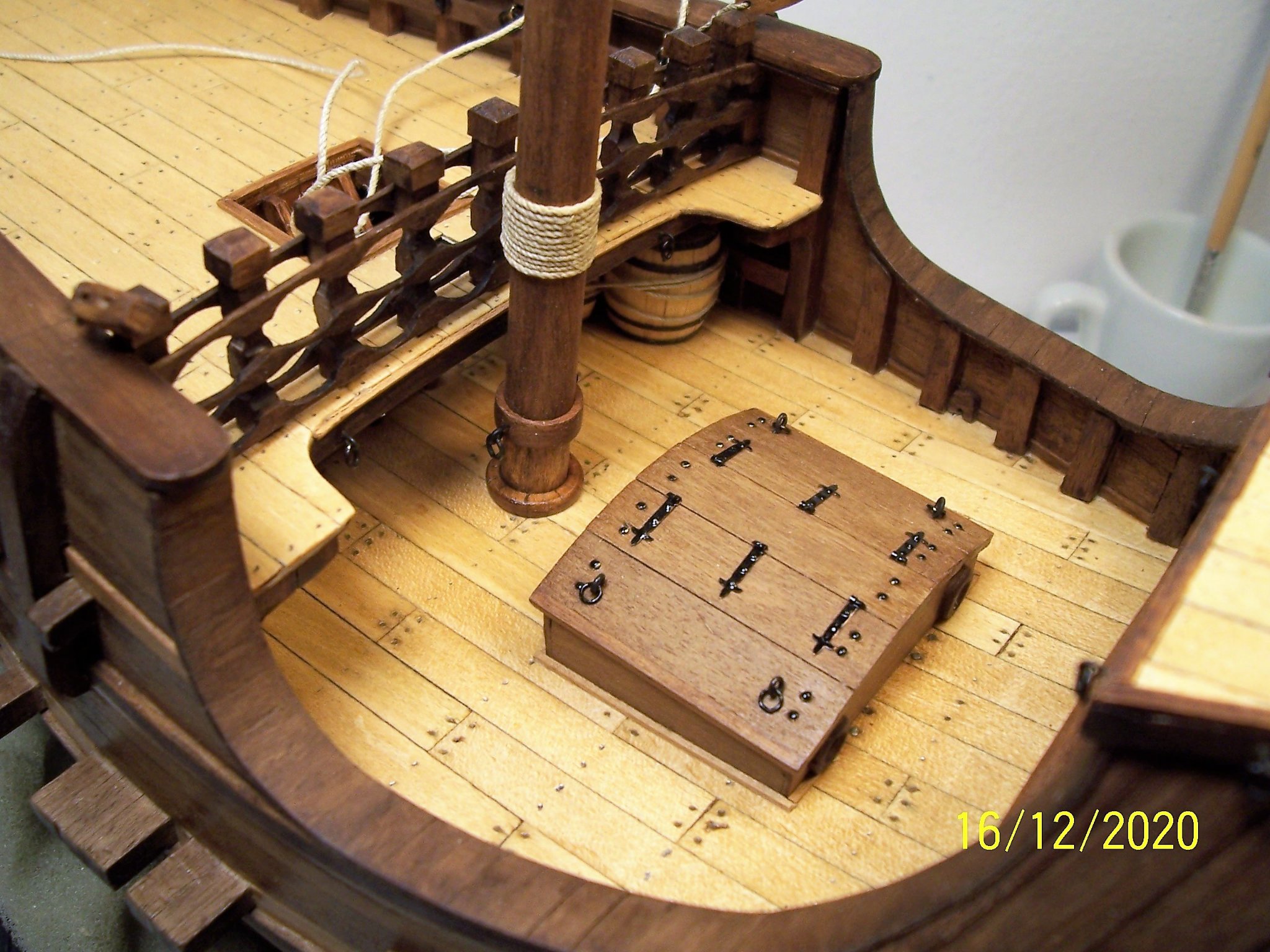
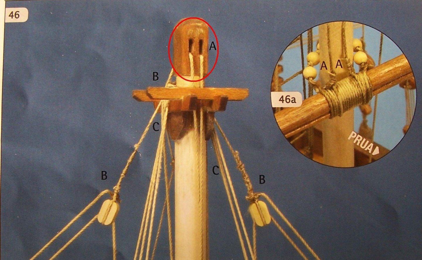
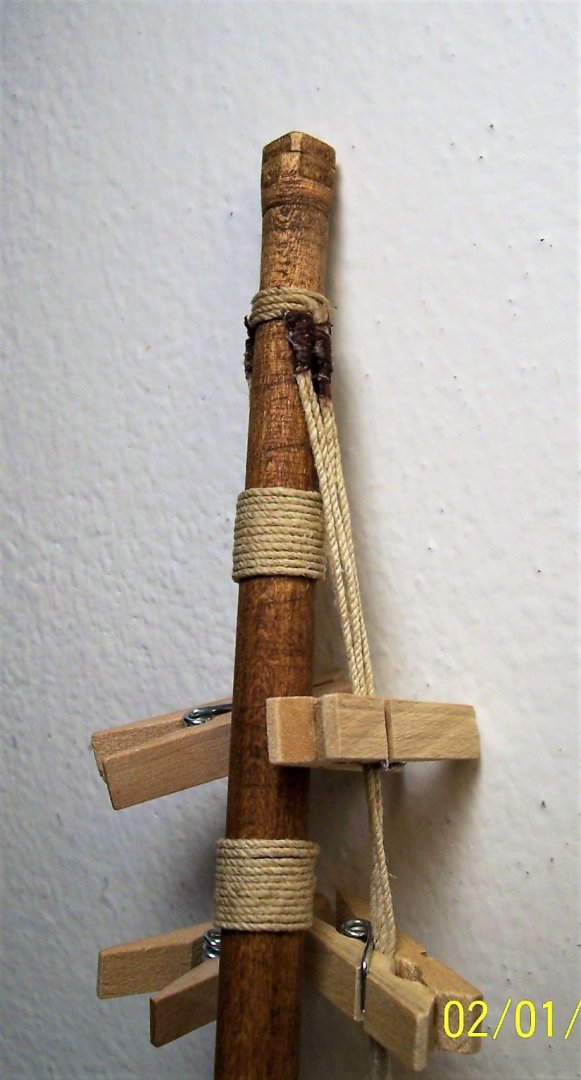
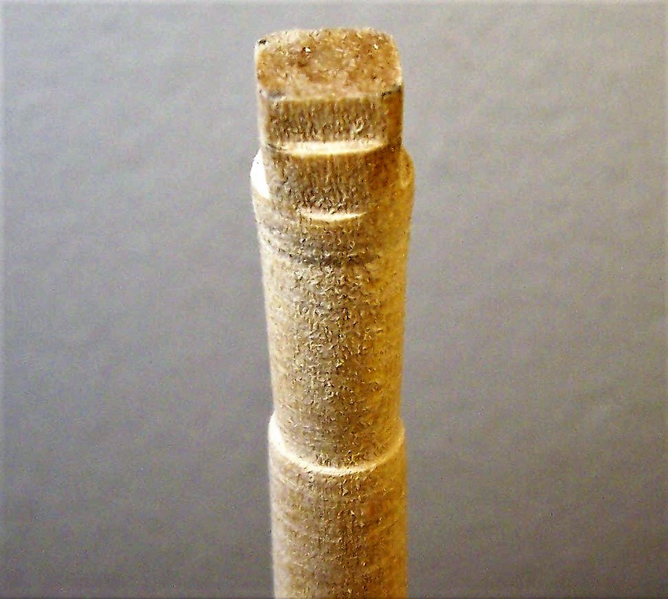
Greetings to all, As for the mast, I will not follow the instructions: here the shrouds pass through the hole in the bottom of mast top. Contra, I will tie the shrouds under the mast top, as in fig. 1, 6 or 8: from: "Sartie, stile mediterraneo" written by Pino dall'Orco. To provide a support for them, I shaped a slight dent. I also squared off the top for the mast hound support, and a little further down I filed the mast to create the supports for trestletrees and transoms: Since I did not prepare a suitable seat for the mast at first (like wisely did Clark Griswold in its Coca), I inserted the tip of a nail into the center of the mast and then pressed it onto the false keel. All in all, the mast is now already quite straight without the use of glue. Then with the shrouds we could do the final correction. The mast was painted dark walnut color. The manufacturer does not provide bindings around the mast. Since they are often represented in the images of that time, I thought to put them because I think they enrich the model, even if the tree is not composite: I also added some details to the base of the mast itself: And that's all for now; good work everyone! Rodolfo


-
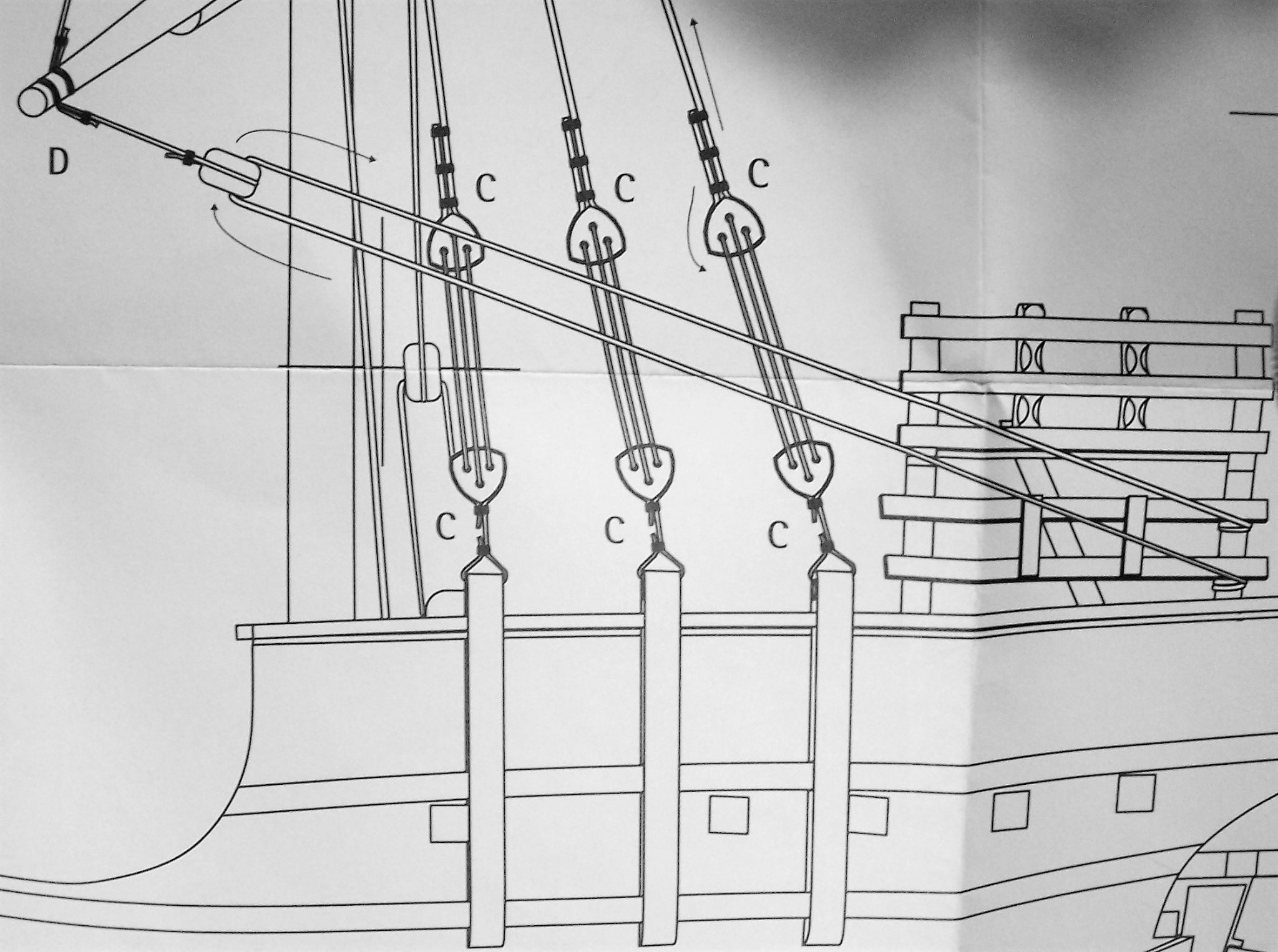
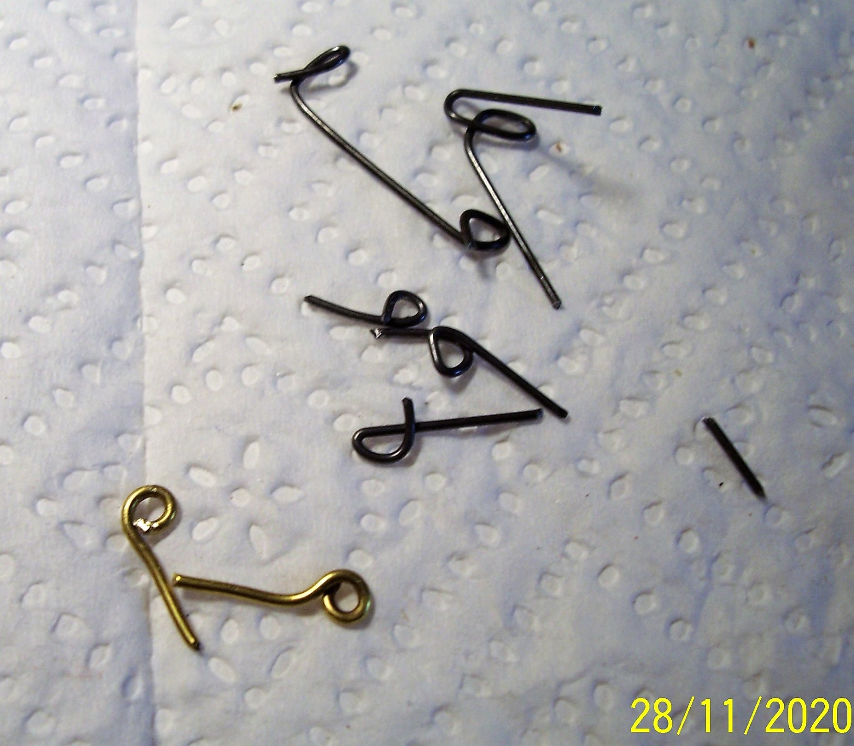
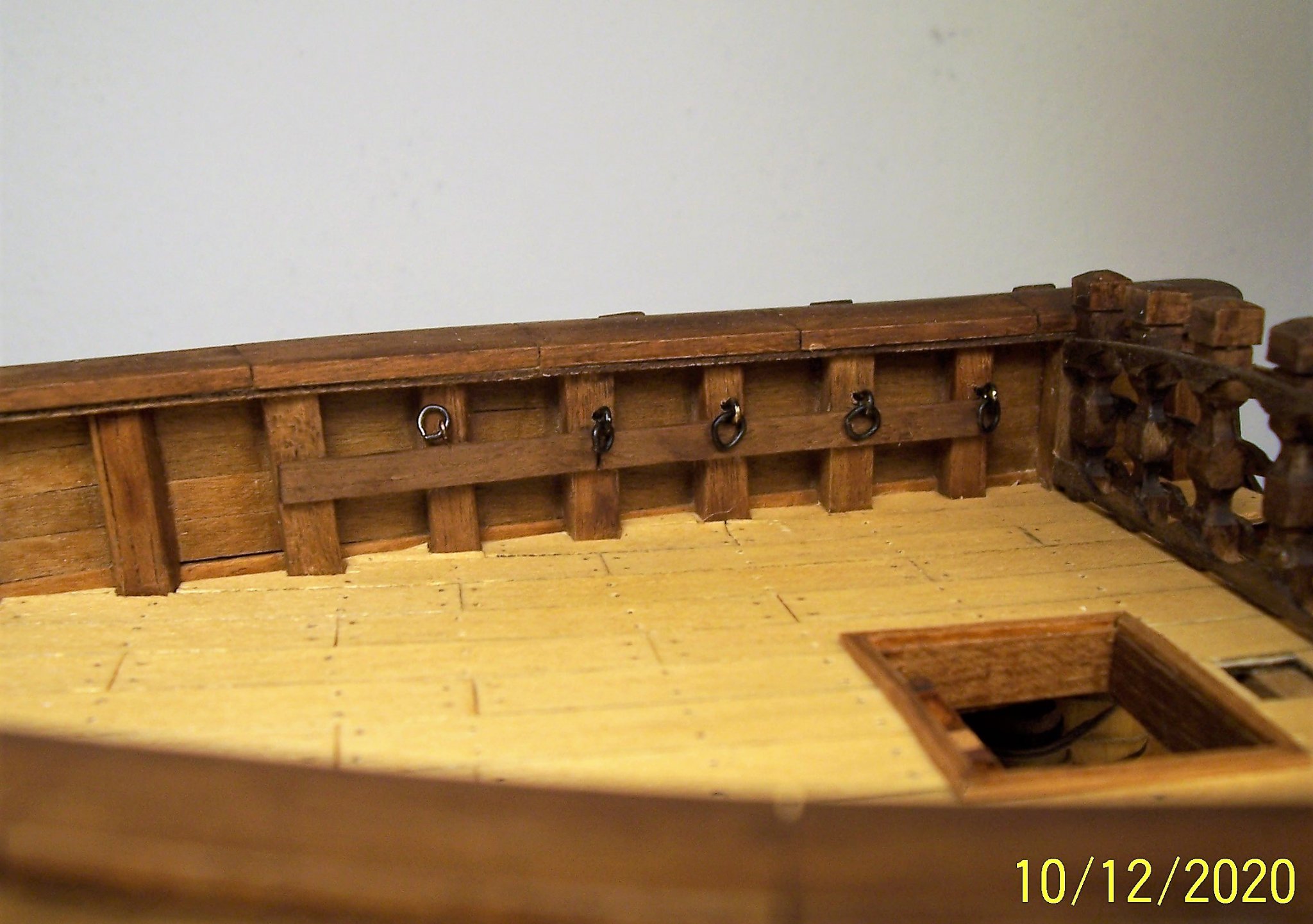
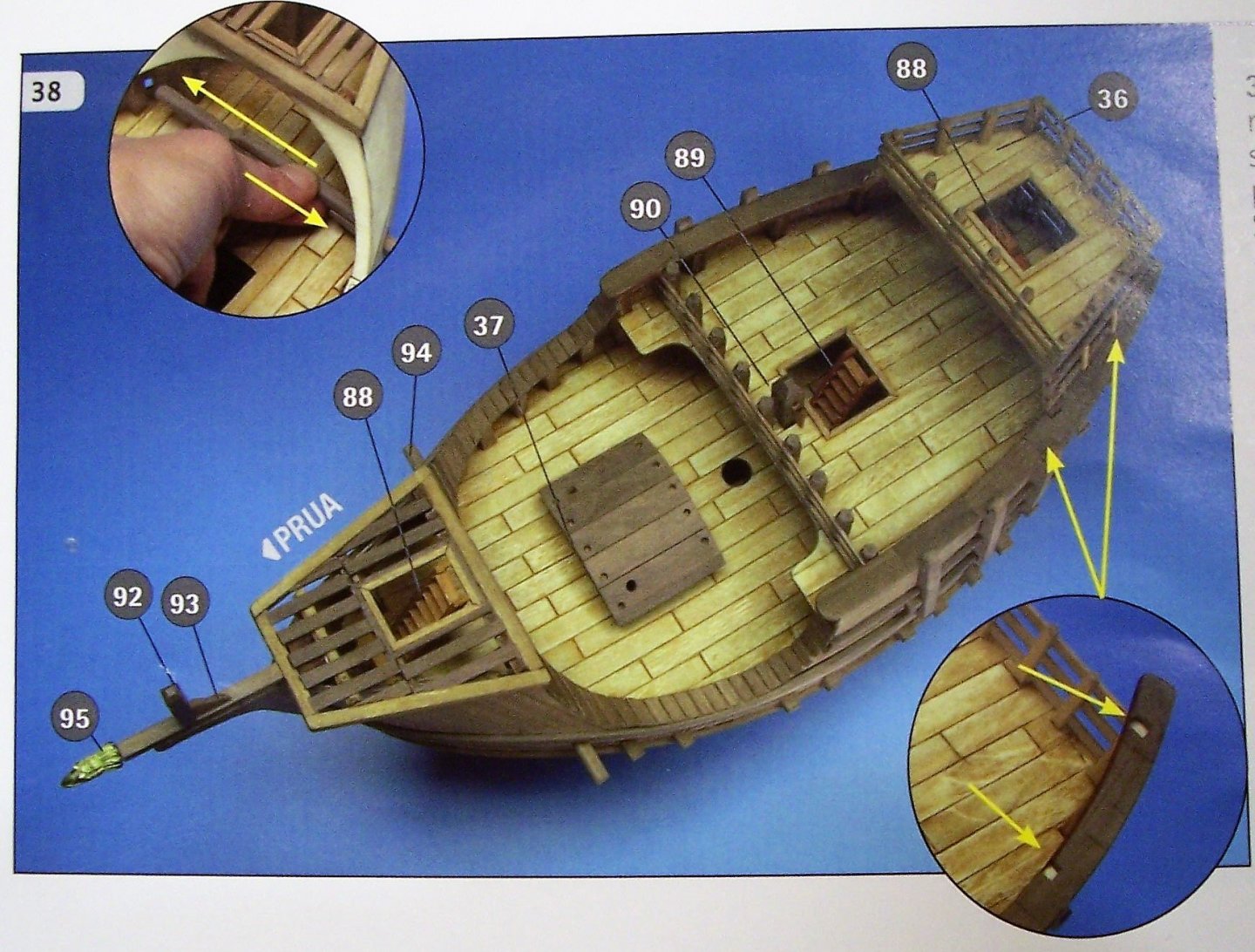
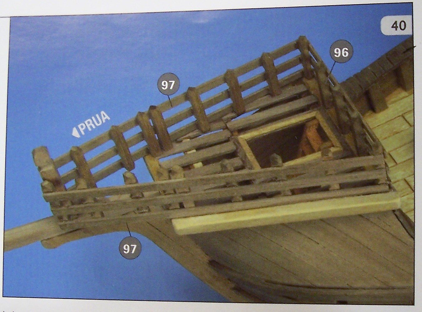
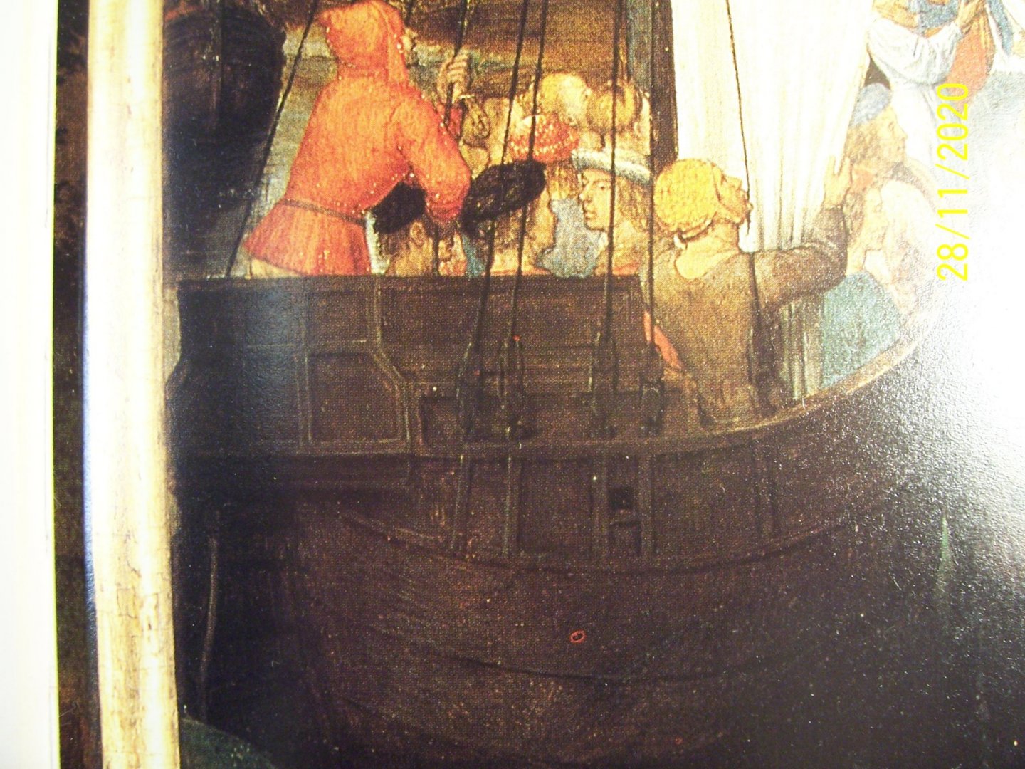
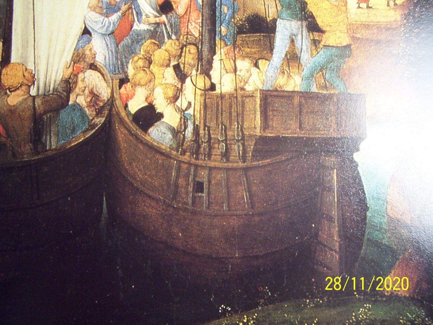
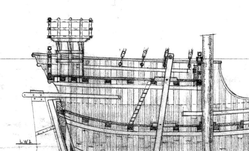
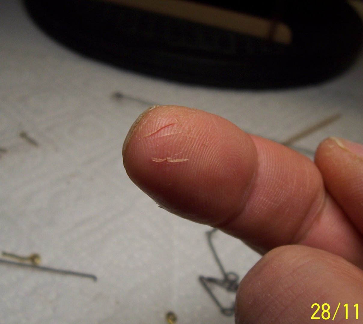
Greetings to all and Thanks to Bigpetr and Steven for the encouragement! Hi Steve, about the equipment for medieval ships, maybe searching with patience something can be found, like these blocks of a small Polish manufacturer: Unfortunately they are temporarily out-of-stock and so I have to build them myself. Returning to our Cocca, at this point AMATI suggests to assemble the stern castle, the rack with the cleat, the pole and its bracket, the figurehead and the rails at bow: . This procedure is correct if we build the shrouds according to the project AMATI, according to which they are fixed with rings on top of the vertical reinforcements: . This solution is also possible because a painting from before 1489 ("Reliquary of St. Ursula" by Hans Memling) shows a similar solution, although with blocks instead of deadeyes: However, the Nao di Matarò clearly has the shrouds fixed on the inside, so it remains to be decided whether to fix them to the deck or to the bulwark stanchions. Examining the photos of the Nao, I thought I saw a block fixed with a ring to the deck, but others seem to be fixed to the side. For this reason I decided to follow the solution shown in this picture, with the shrouds attached to a ring planted on a stanchion above a horizontal beam. In order to do this, it is necessary to postpone the positioning of the castle and the rails, which would interfere with the laying of the shrouds and the stay. In addition, eyebolts and rings are needed, which are not included in the AMATI package. Fortunately, they are easy to make, with steel, iron, brass or annealed copper wire: Be careful with the harmonic steel wire, it can injure your fingertips! The only one that came out right I'll put in the bow, where I will tie the stay; . The last photo shows the final layout of the horizontal beam and shroud attachment points (eyebolts plus rings): The three fixed cables per side proposed by AMATI seem to me a bit 'little ... I think I will put at least four. At this point we need to think about the blocks... Have a nice evening! Rodolfo


-
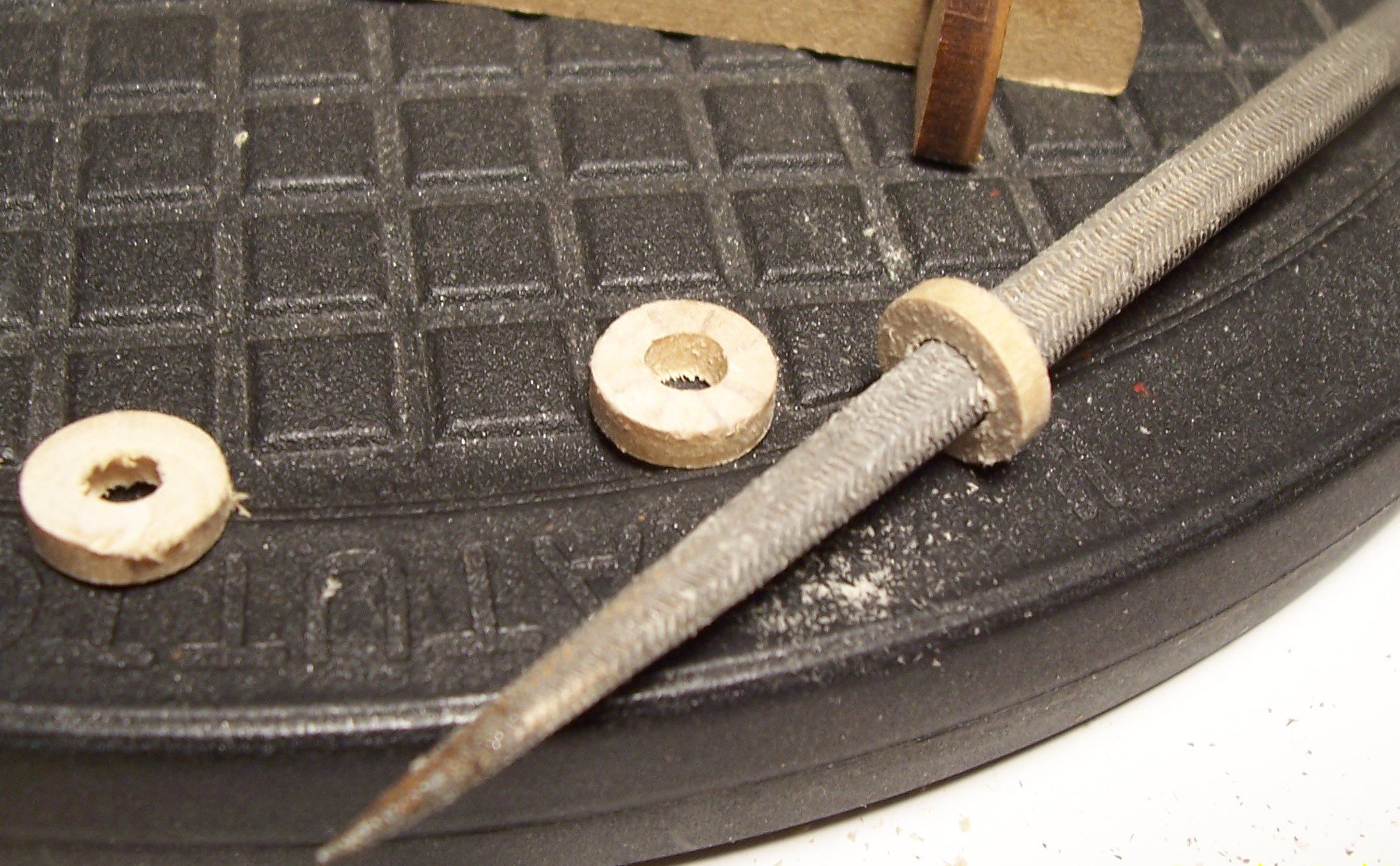
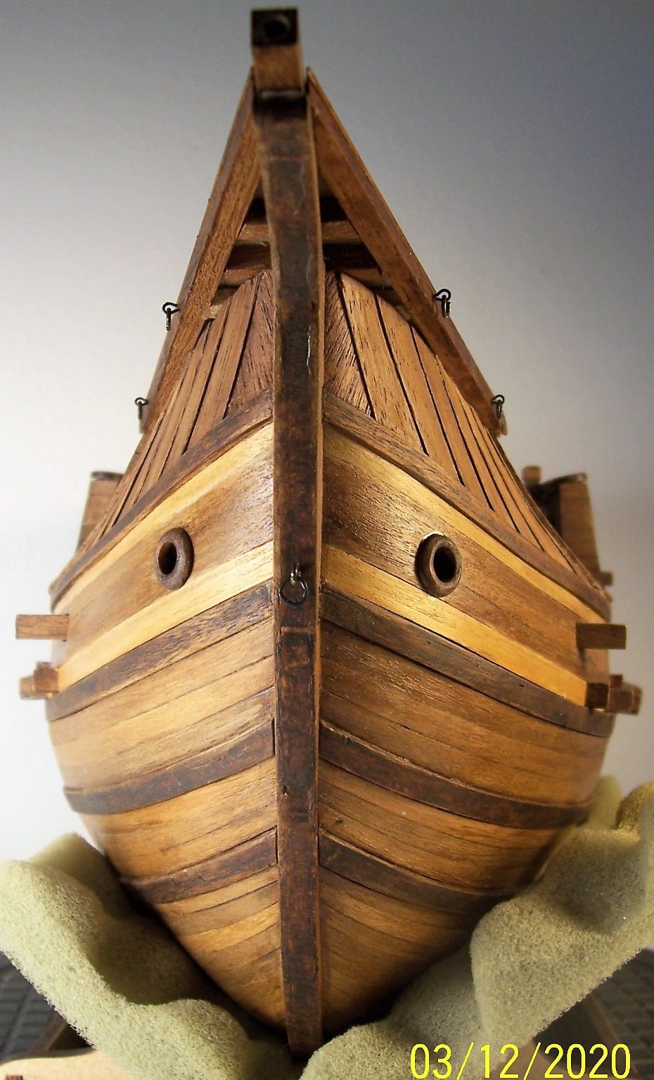
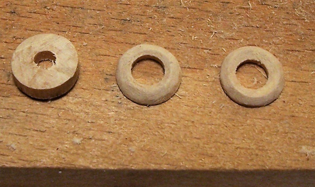
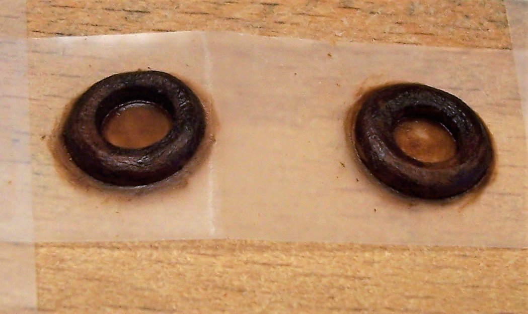
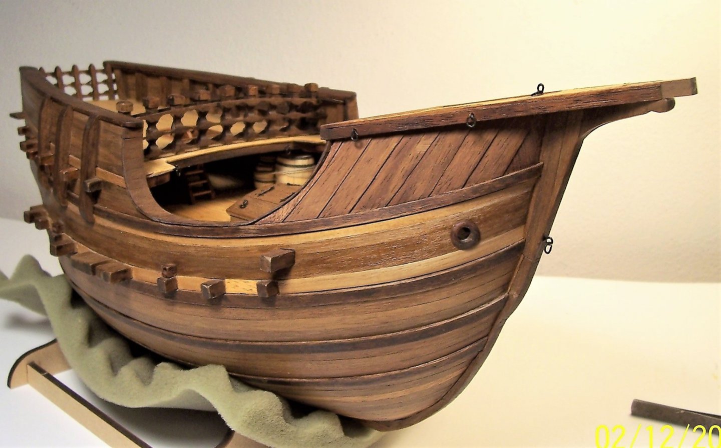
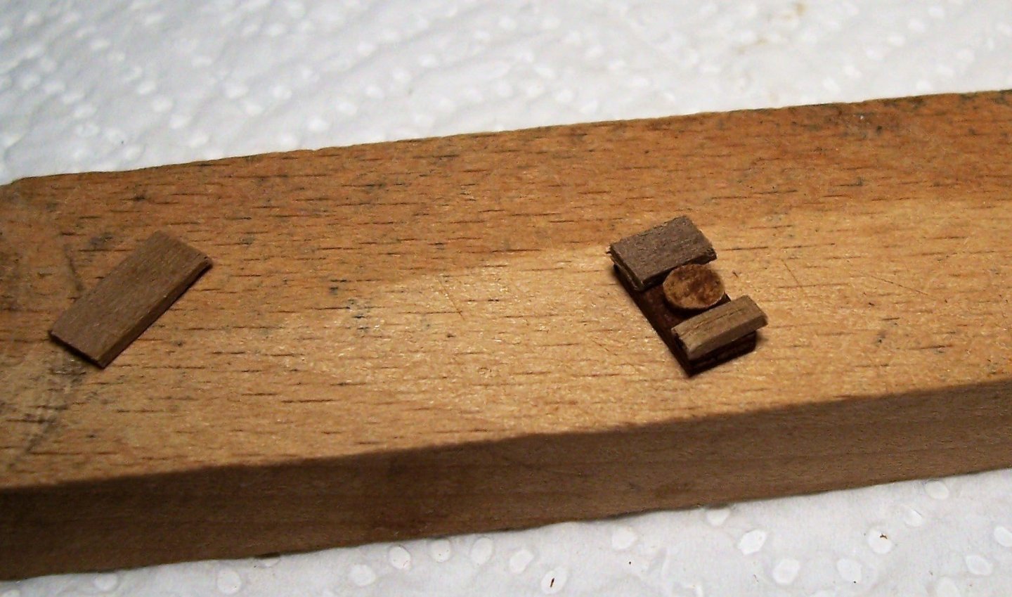
Greetings to all! In the meantime I have put on the hawse eyes, not foreseen in the AMATI plans and not always visible in contemporary illustrations. The 10 mm rod for the main mast is exceeding in length; I made a central hole with a diameter of 4 mm, cut two slices of 4 mm thickness and shaped them. Outside with file, round cutter and sandpaper; about the side that needs to be glued, I shaped it in situ placing a piece of sandpaper on the hull where it should have gone and rubbing until it acquired enough curvature. At the end, the thickness of the hawse eyes became 1.5 mm. The diameter of the internal hole obviously has to be brought to the size of the one on the hull with round file, once the glue has taken hold. Having used an impregnating agent for the wood of the hull, it follows that Vinavil makes a very poor grip; for this reason I used a two-component epoxy glue. Have a good job at your shipyards! Rodolfo


-
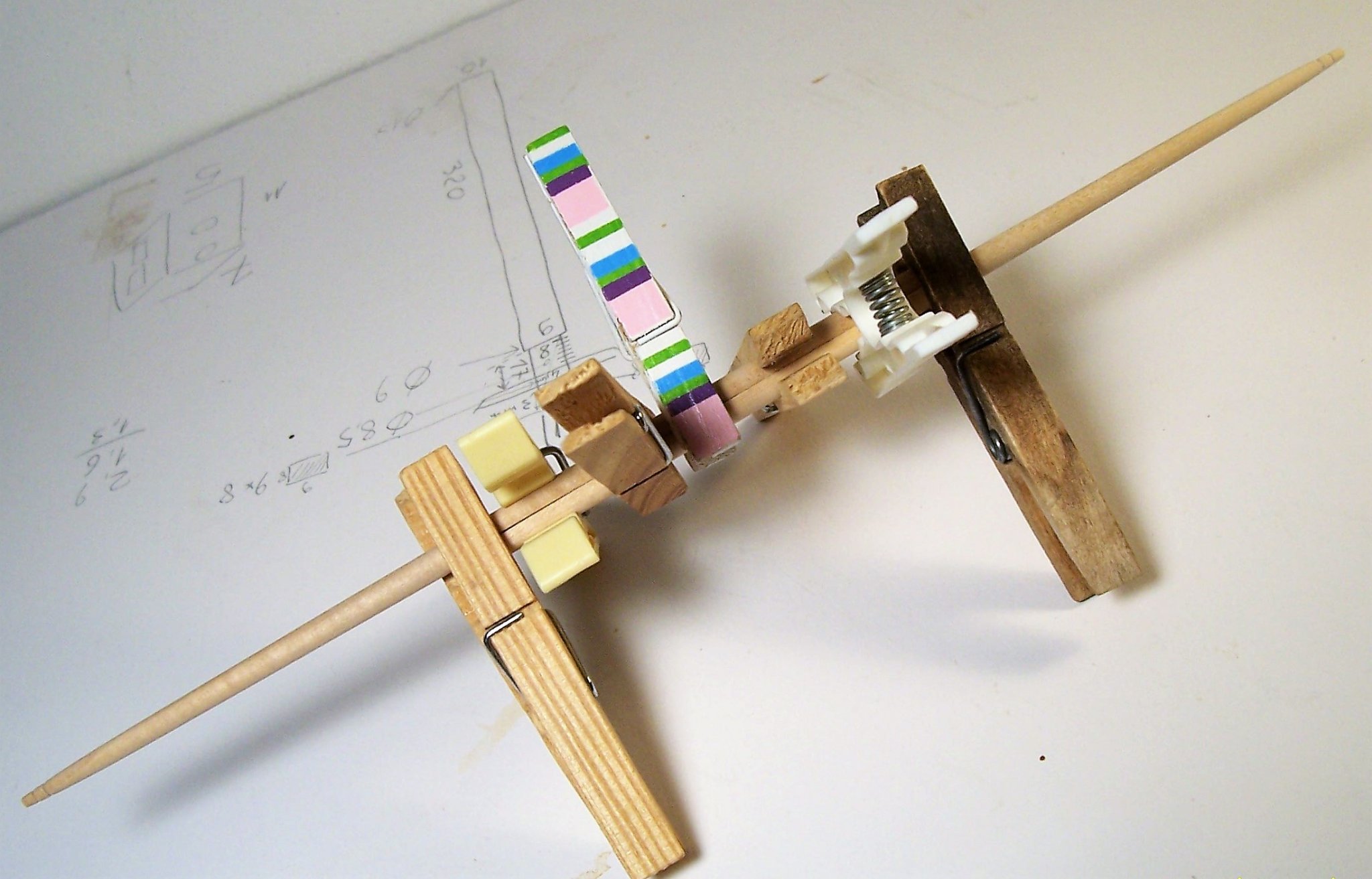
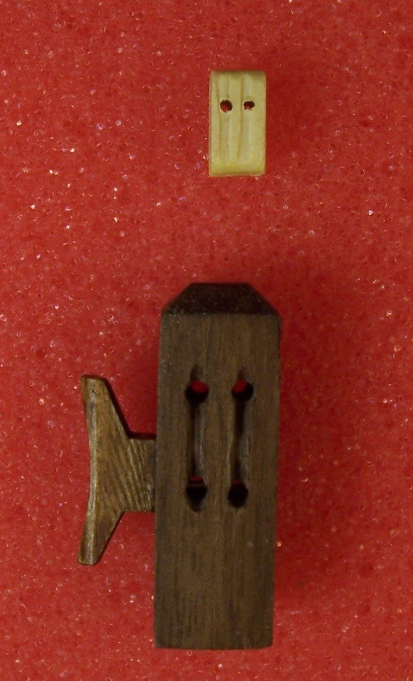
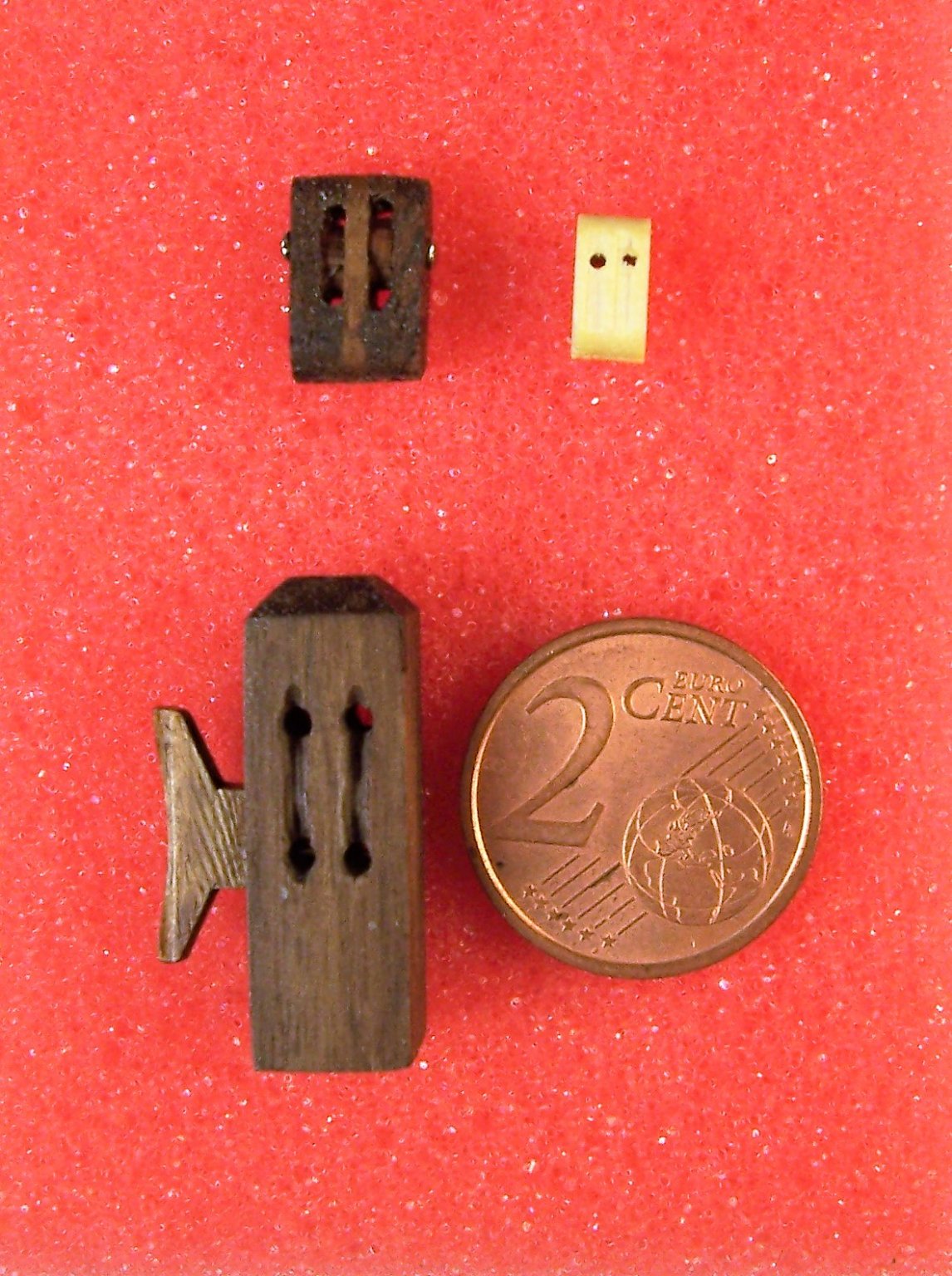
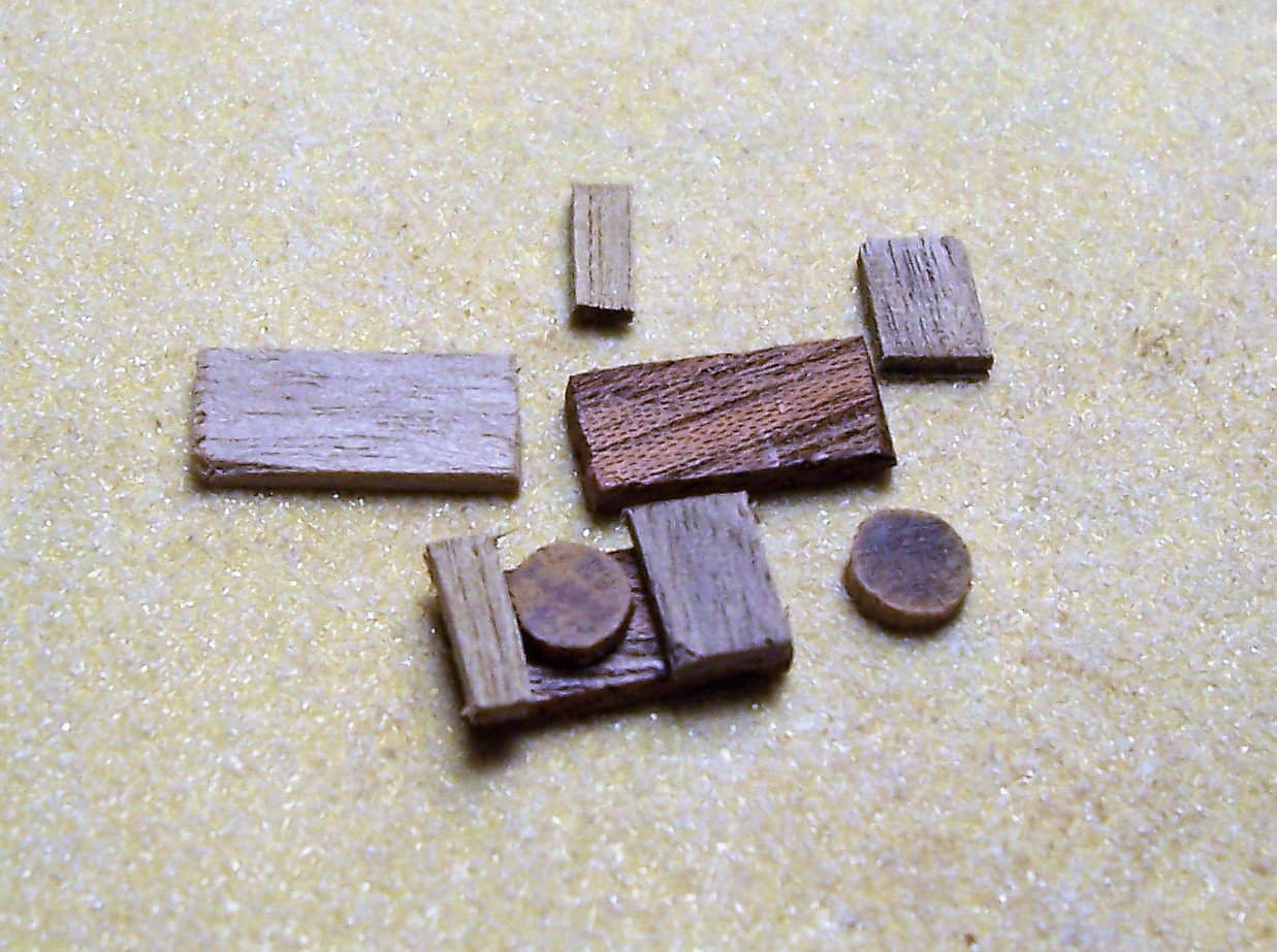
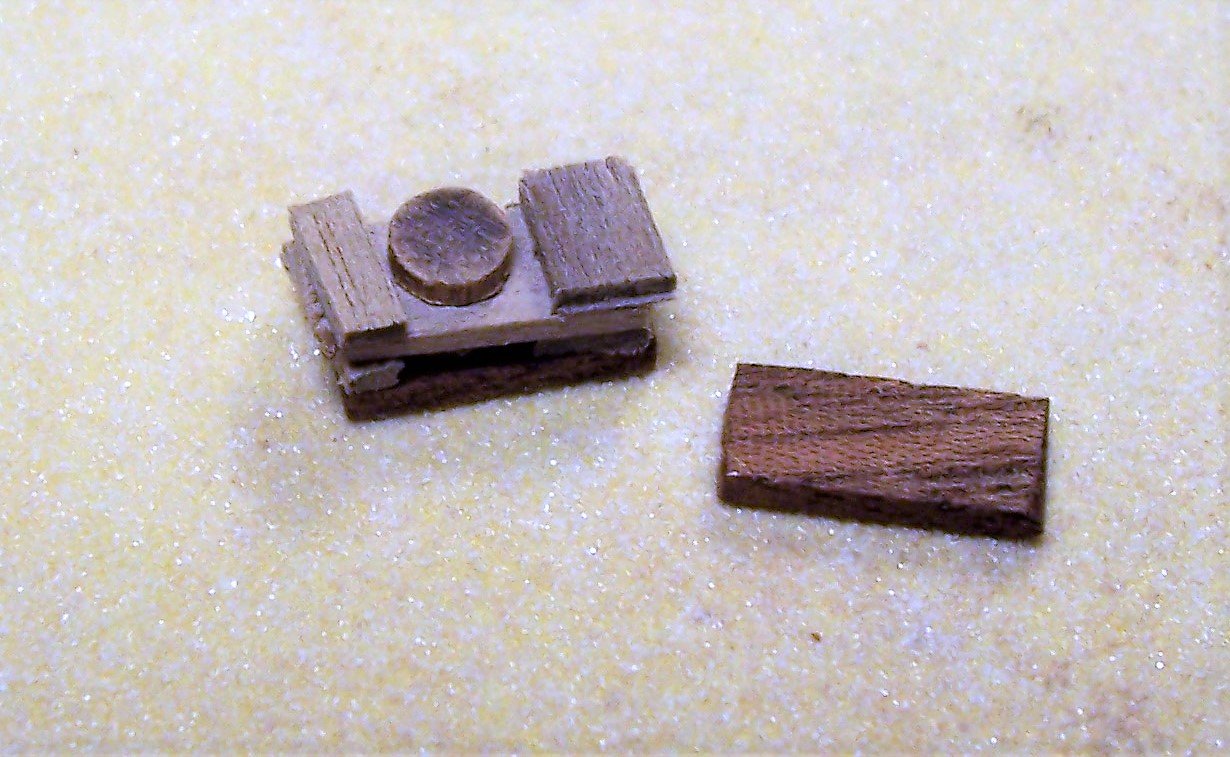
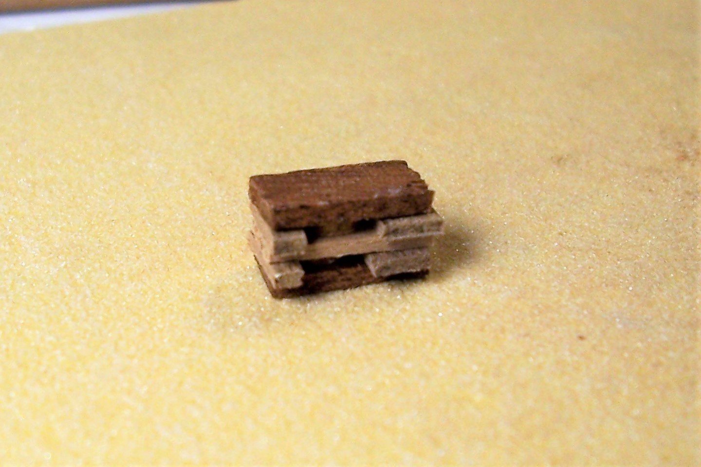
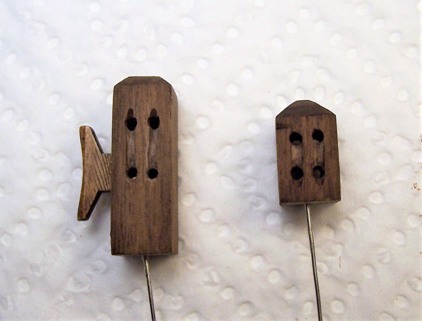
Welcome everybody! The construction of masting immediately presents the first problem, which is the size of the blocks. I think there is a disproportion (first photo) between the rack and the block of the halyard: In commerce I have not found blocks with the particular shape in medieval ships and so I decided to build it with pieces of wood, slices of wood rod and pin heads: The four pins serve as spacers between pulleys and edges during gluing: A through hole at the top, a countersink for the openings, a light scraping and a walnut impregnating paint complete the work: The head of the pin will be painted in matt black, of course. Final dimensions are 11x7x5 mm, (last photo). Of course this implies having to build from scratch all the blocks that I will need... Good job to everybody! Rodolfo

-
Congratulations! I think that restoring a sailing ship is more difficult than building it from scratch. You are doing a great job! Rodolfo
- 740 replies
-
- 7
-

-
- Tudor
- restoration
- (and 4 more)
-
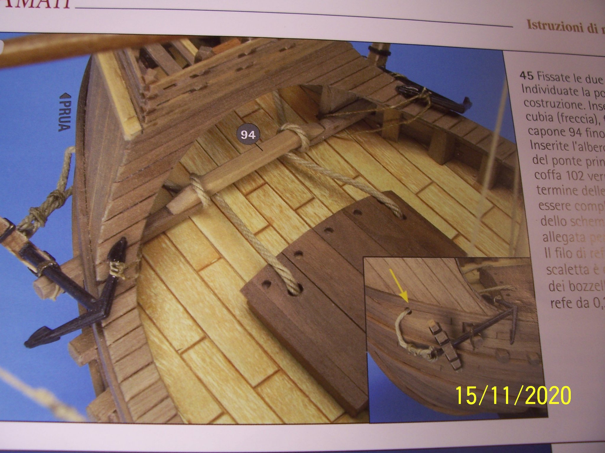
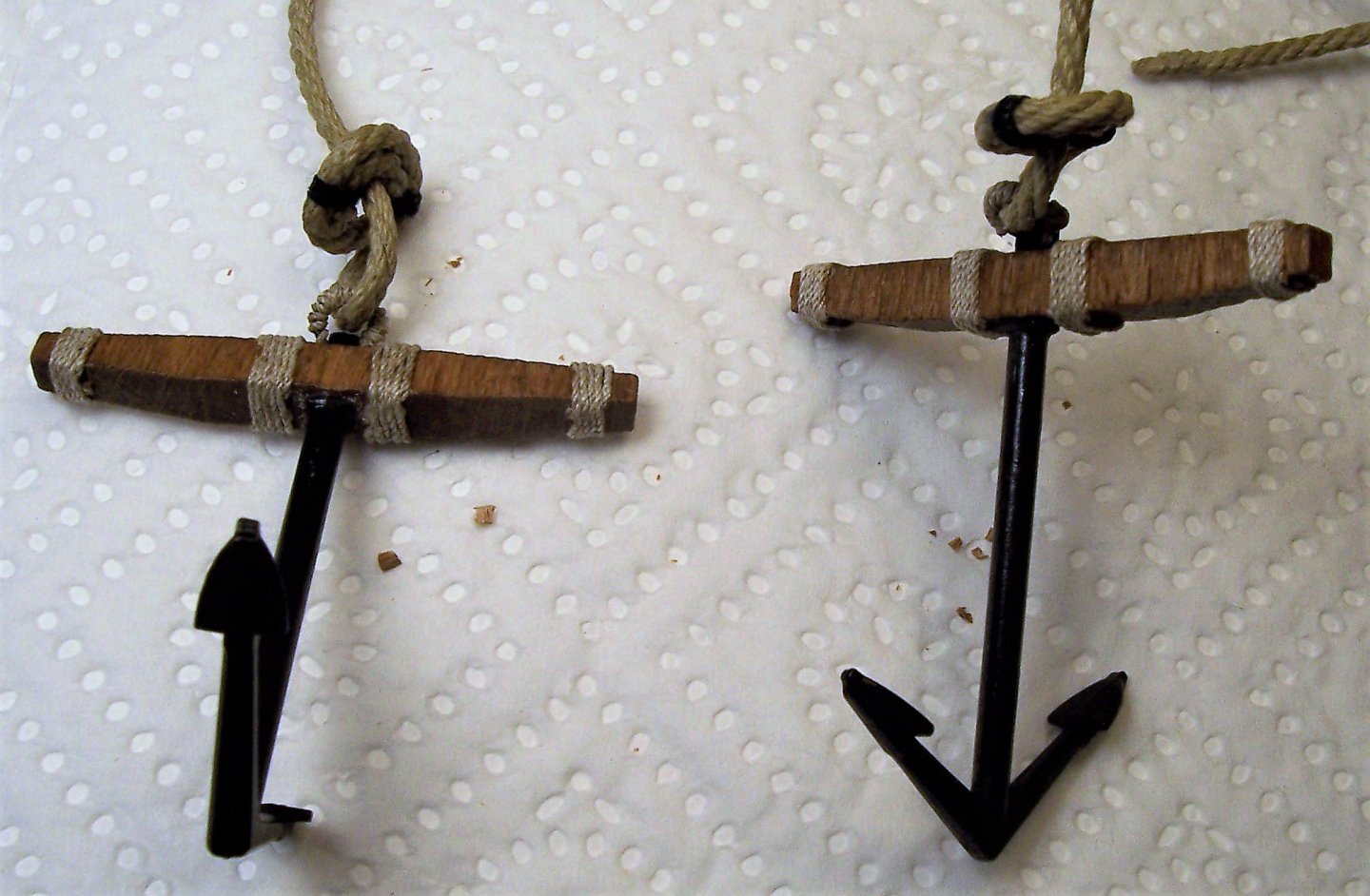
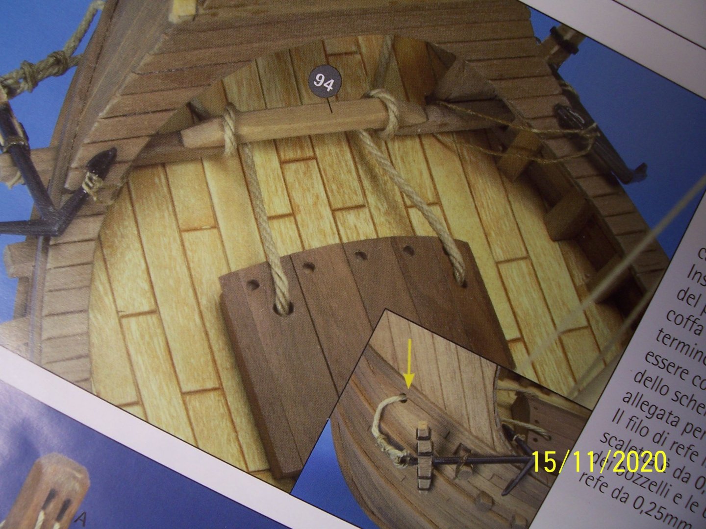
Thanks Louie and welcome you all! The anchors according to AMATI should have four square metal rings to keep the sections that make up the stock together: After covering the stock with walnut veneer, I preferred ligatures with ropes. At the anchor ring I preferred to tie a knot that I found on Luciano Santoro's manual "Il modellista navale" Ed. HOEPLI: Next we will try to guess the path of the anchor's ropes, since it's difficult to understand examining contemporary documents. Have a nice weekend! Rodolfo.
-
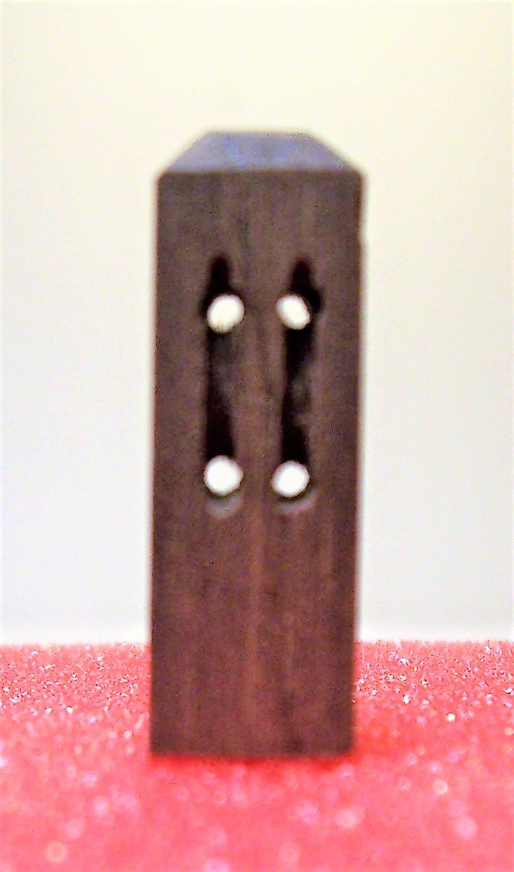
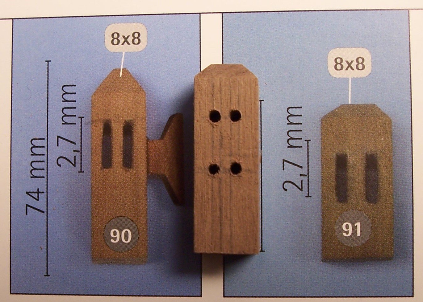
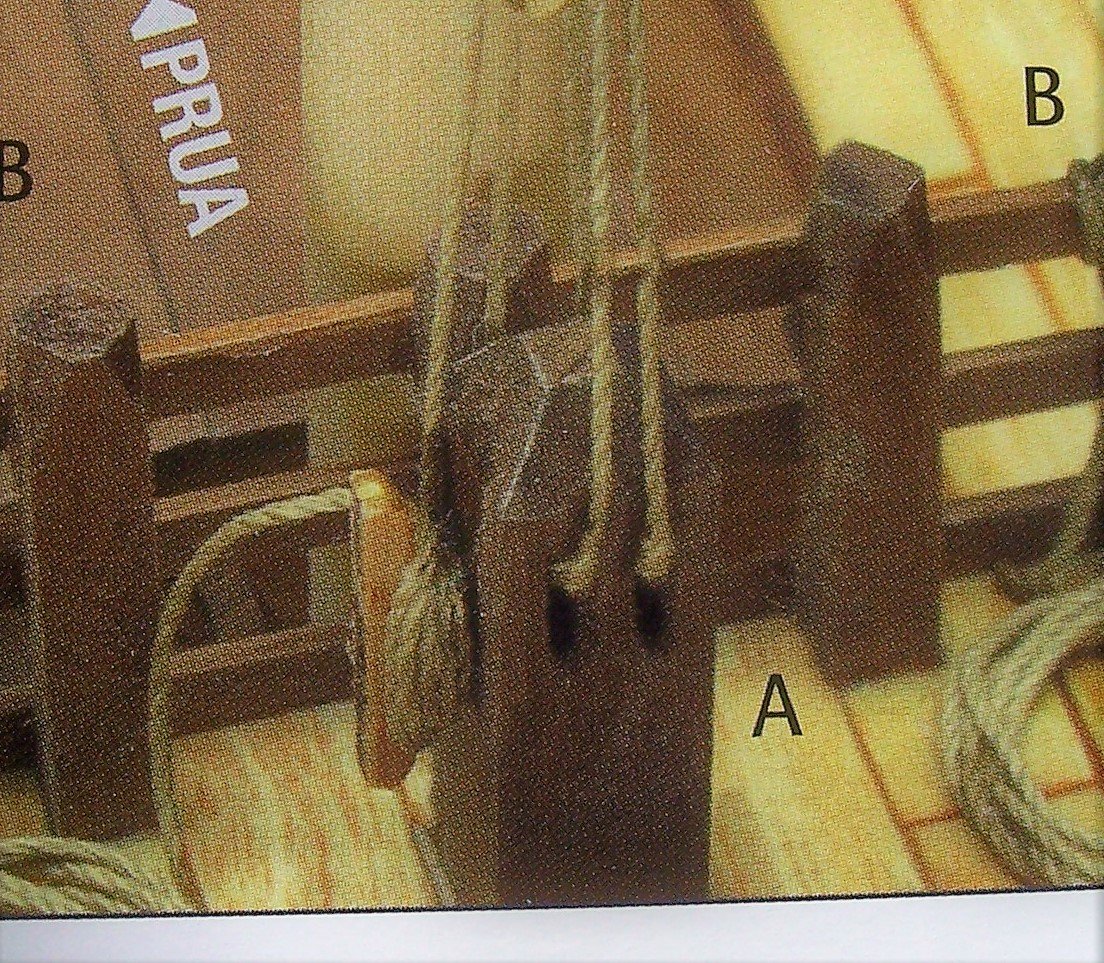
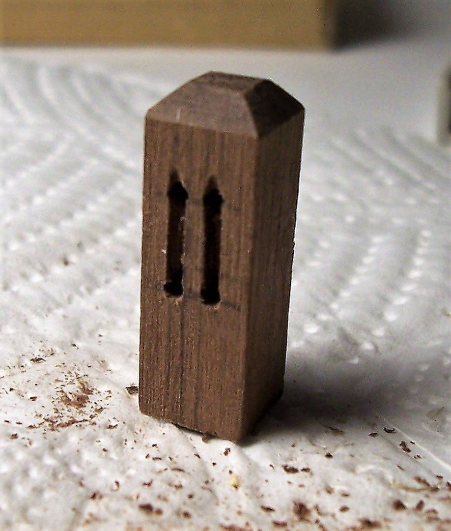
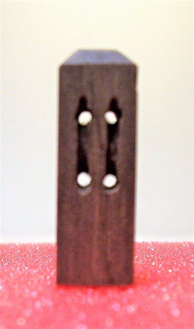
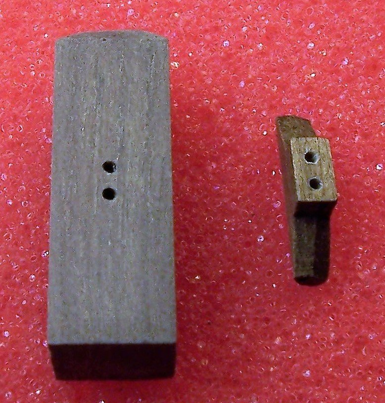
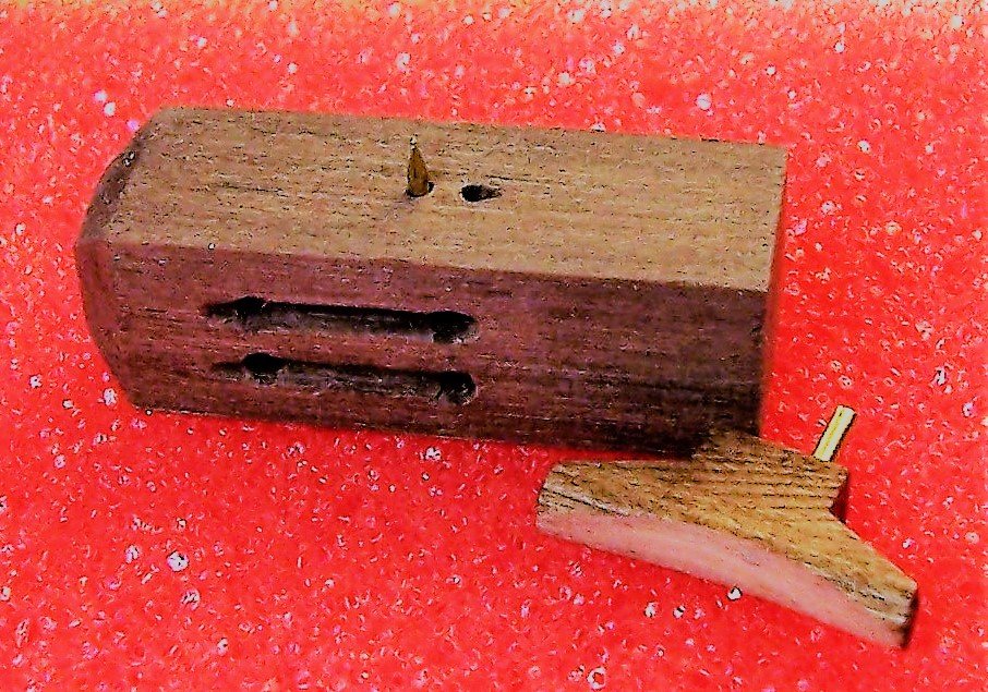
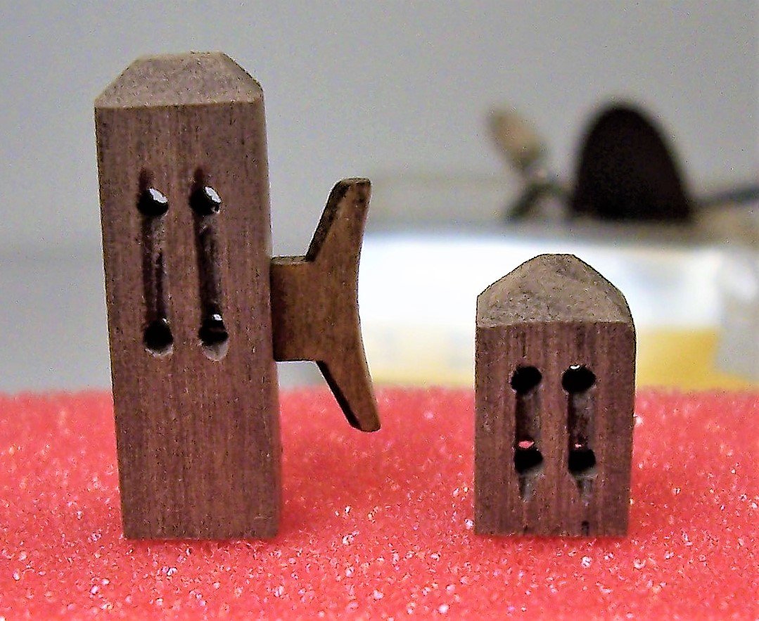
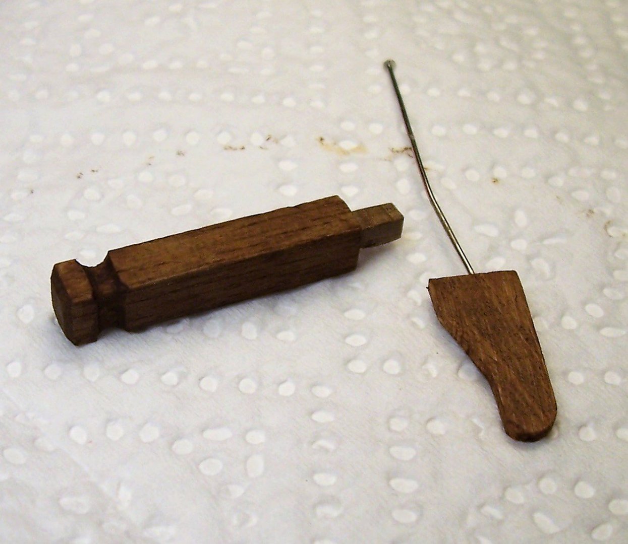
Thanks, Louie! Building the rack, instructions indicate a height of 74 mm: ; It's clearly a mistake, because a man 1m and 70 cm high in 1/60 scale is about 28 mm. I thought a printing error and then 74 was a 24. It also indicates two 2.7 mm slots; but in this way you DO NOT get the perception that the rope passes through the sheaves: Considering that the sheaves are generally not much smaller in diameter than the width of the case (here 8 mm) I preferred to make two slots of about 8 mm in length with holes above and below and an excavation to simulate the sheaves: The rack is associated with a cleat. Being the gluing area very small, it may be feared that it will not withstand stress. For this reason I made two small holes on the rack and on the cleat and I inserted two pieces of brass before gluing: For the mast hound I did the same work as for the rack, with the hollows and the fake sheaves inside: Here, too, the illustrations in the manual do not give the perception of ropes running over sheaves: Finally, the pole with its bracket (in this case a bracket for the mast, as I will not use any on this model): See you soon! Rodolfo
-
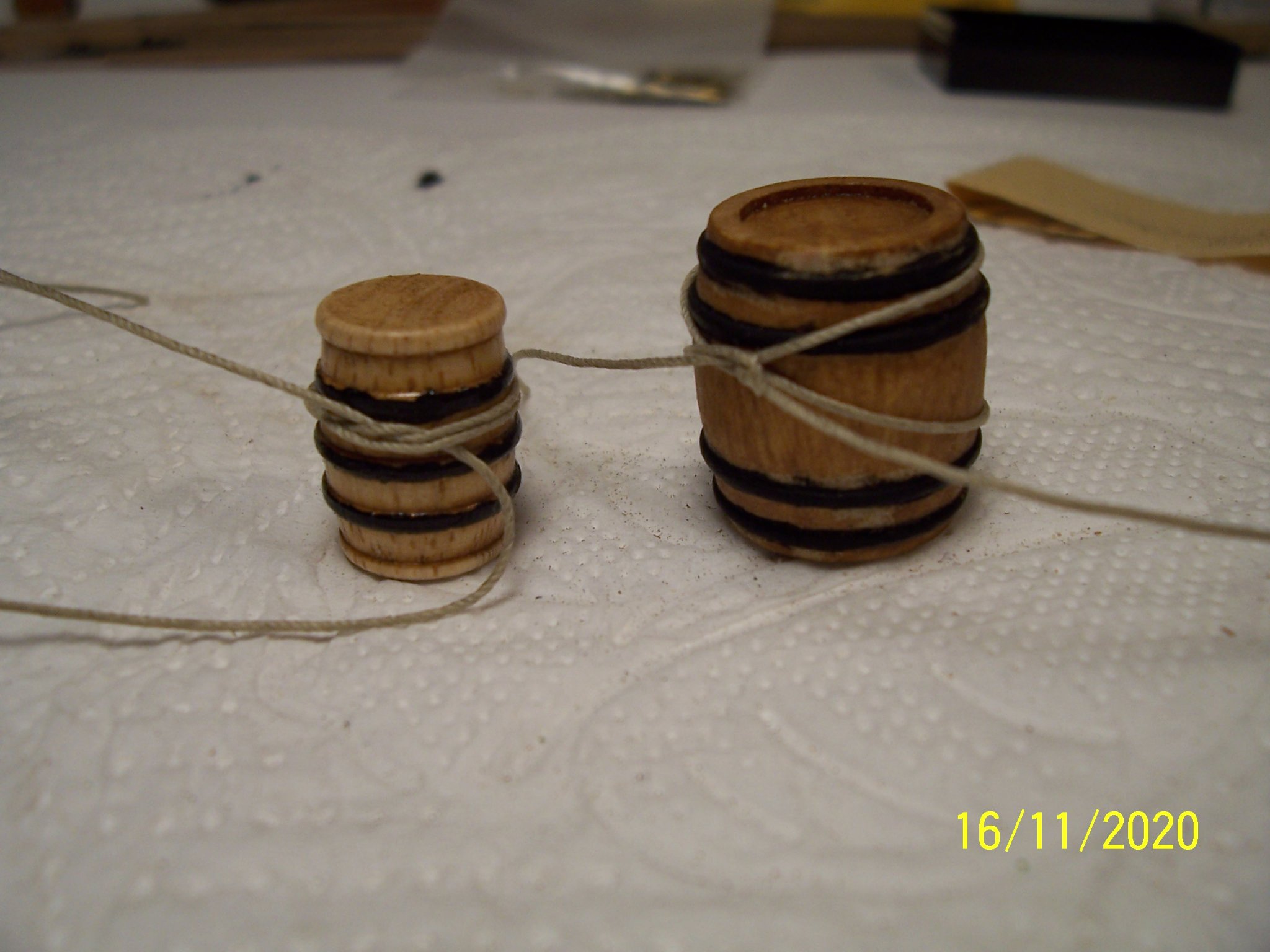
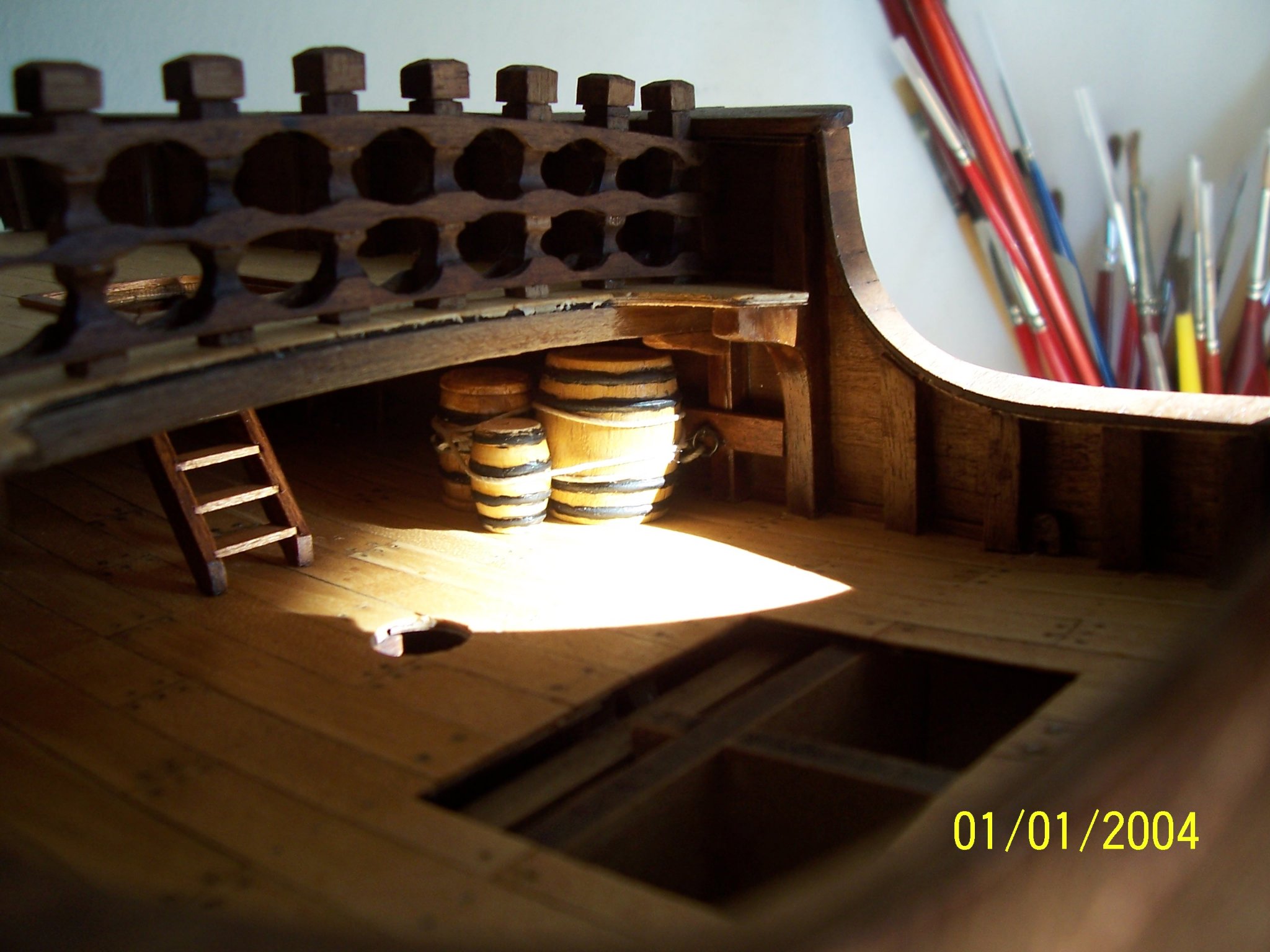
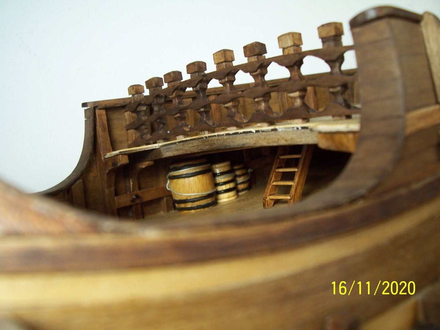
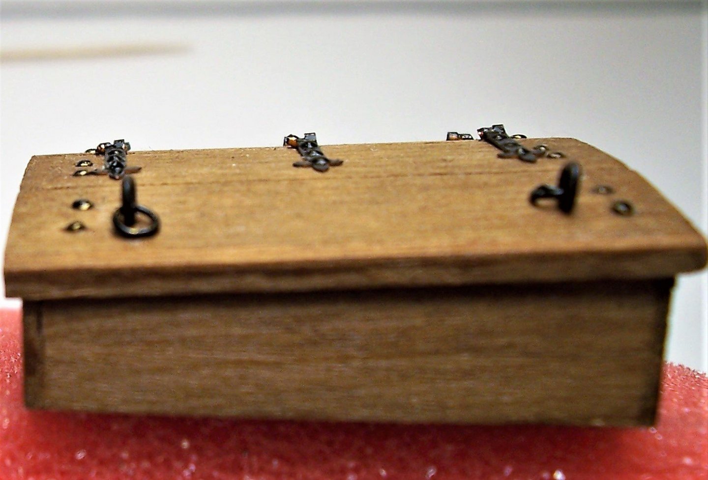
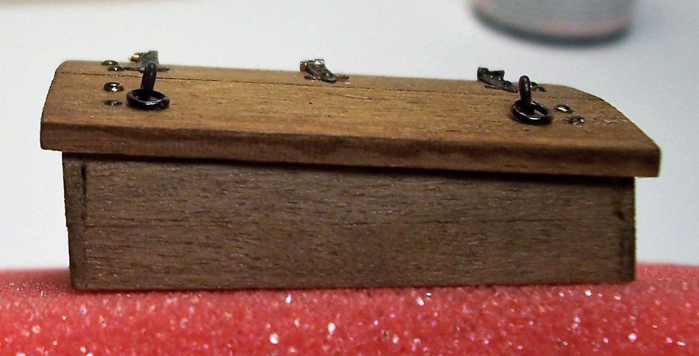
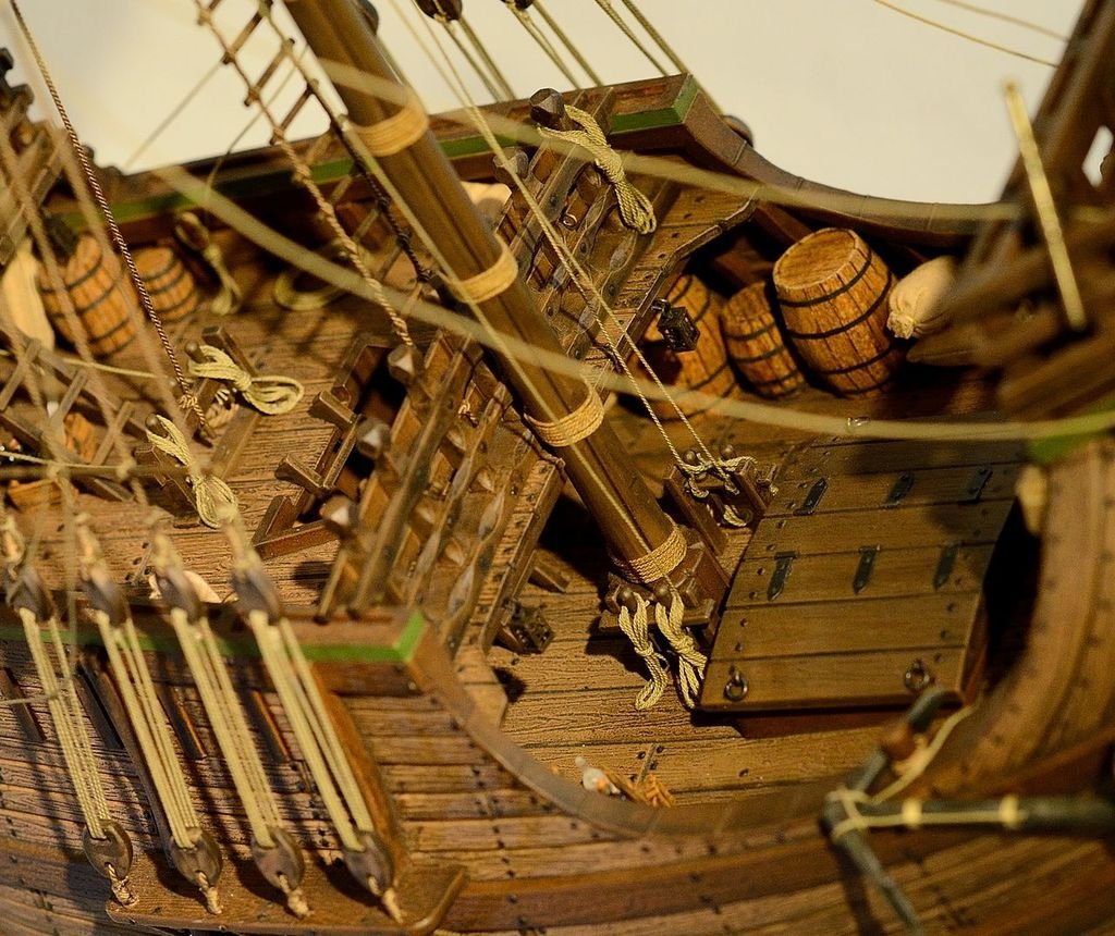
Hi Patrick, I've always slept like a hibernating bear! 🙂 Before continuing with the superstructures, it's better to secure the load; indeed, it is already late because now it has become difficult to get the ropes through the rings. With hindsight, I recommend fixing the barrels before covering the upper deck. I preferred a certain asymmetry, as if the operations were not finished yet. See you soon! Rodolfo


-
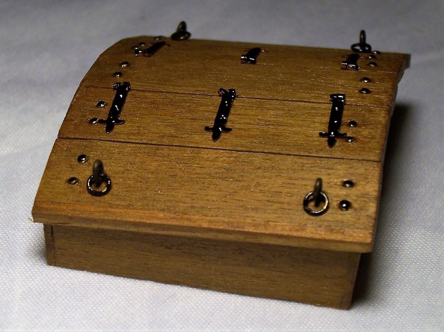
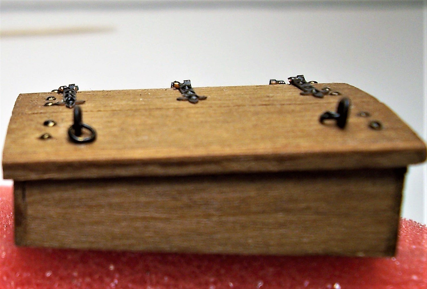
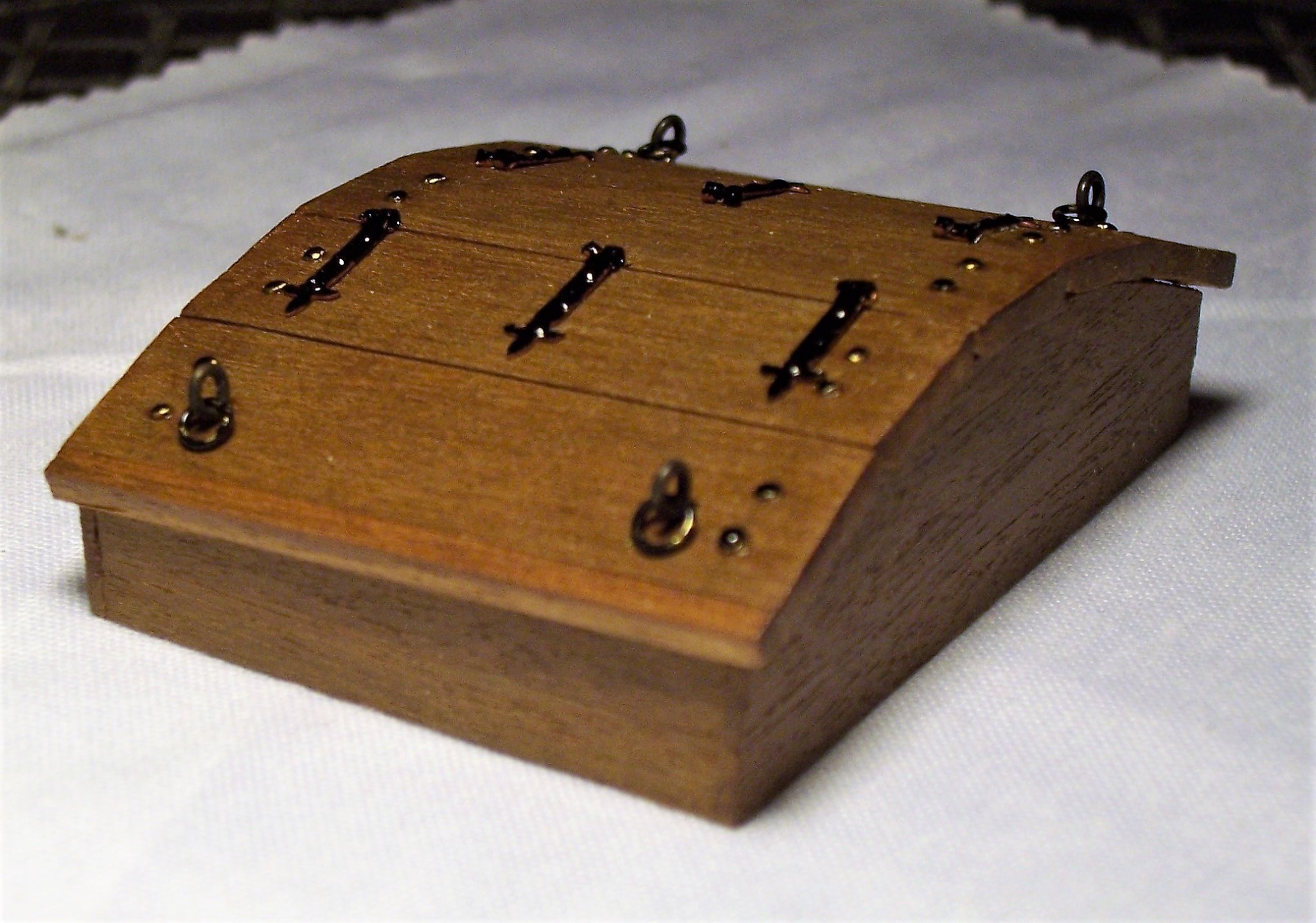
Hi Backer, I have examined the arrangement of the nails and, fortunately, it seems to me that there are no problems. If I had to modify it, maybe I could have damaged it and then rebuilt it. Examining the object sideways, you will see that the rows of nails are not above the side walls: They are shifted inwards; they are assumed to be planted on a support located underneath that holds the boards of the flaps together. I also remembered that the nails on the hinges were reproduced using drops of Vinavil, as I didn't have any so thin. Now, with my conscience in place, I can sleep peacefully and go back to work at my Coca. Rodolfo

-
Thanks to all of you for your comments and remarks always welcome! @ Backer: You're absolutely right! I hadn't thought about it: I saw this beautiful model: and then I copied it without thinking. After all, I'm just a railway modeler...and my commissioners (my family, which doesn't distinguish Bismarck from Titanic) just want a nice ornament, they have no idea of the historical fidelity. Nevertheless, since the piece is not yet in position, I think I will modify it in order to make it more plausible. I am sure that if I don't do it now, in the future I will be in pain... Rodolfo
-
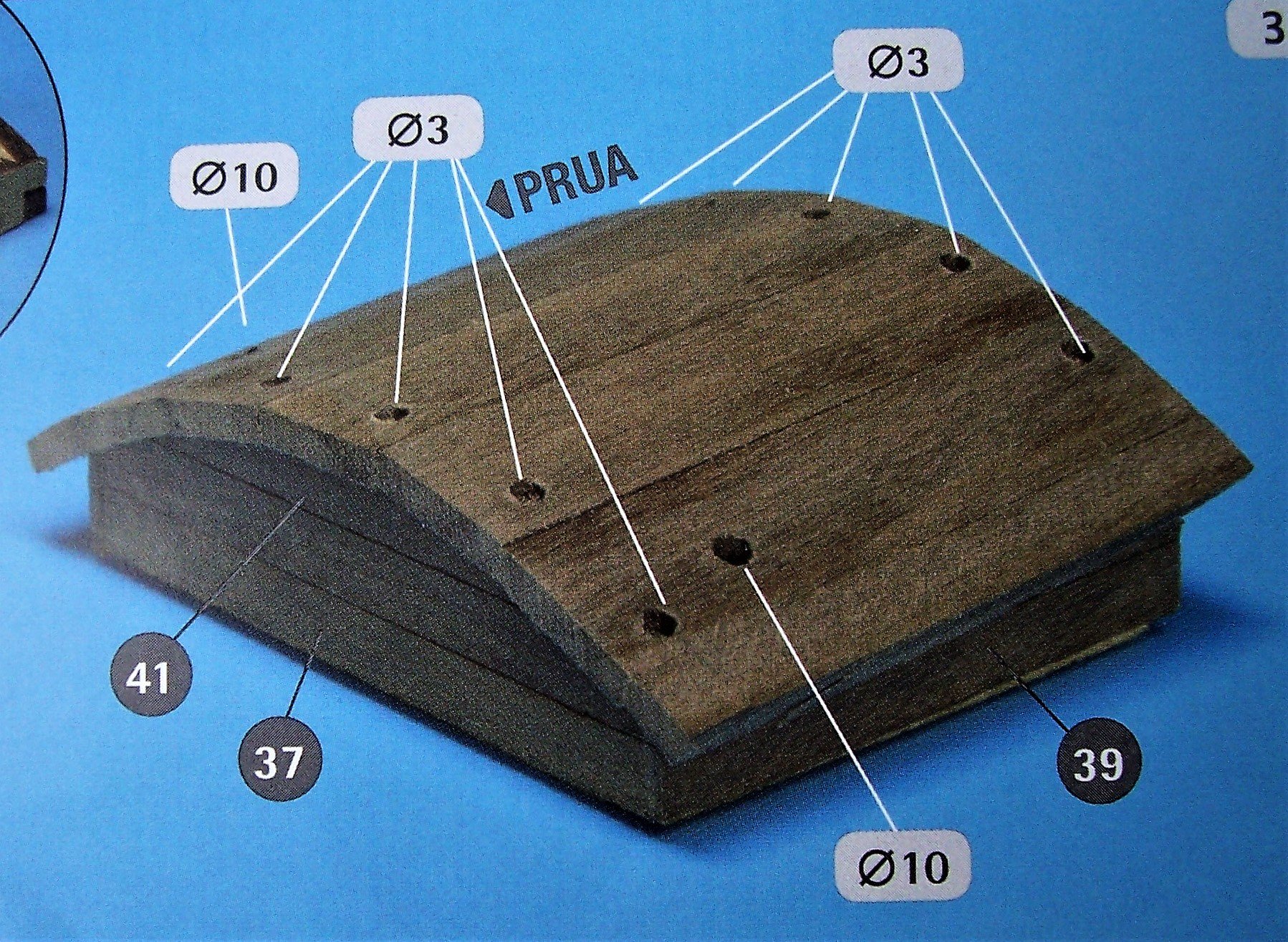
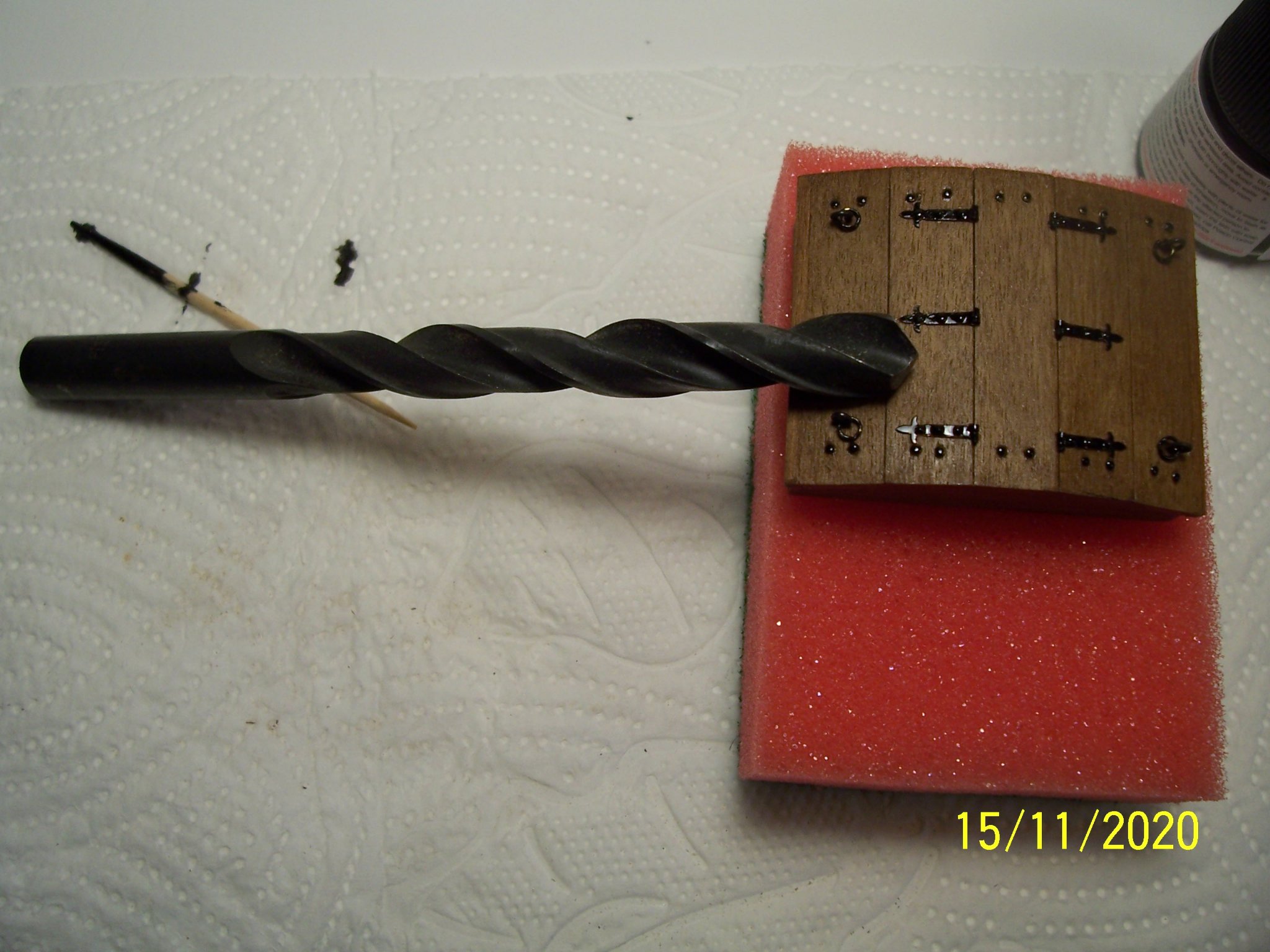
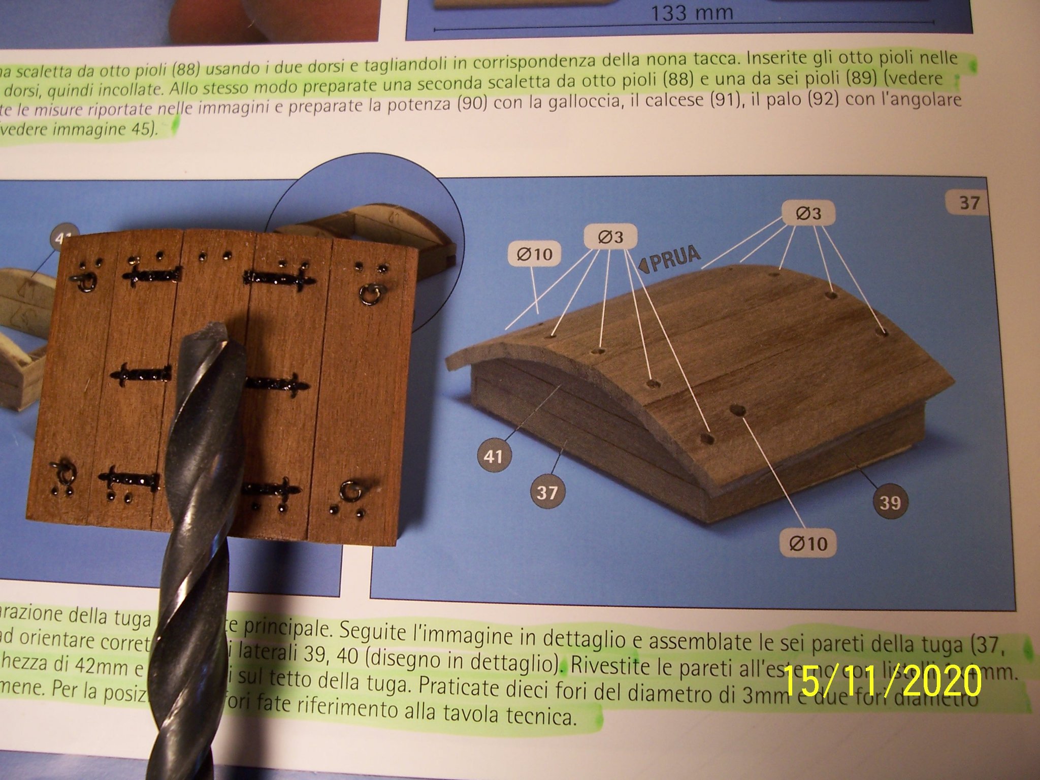
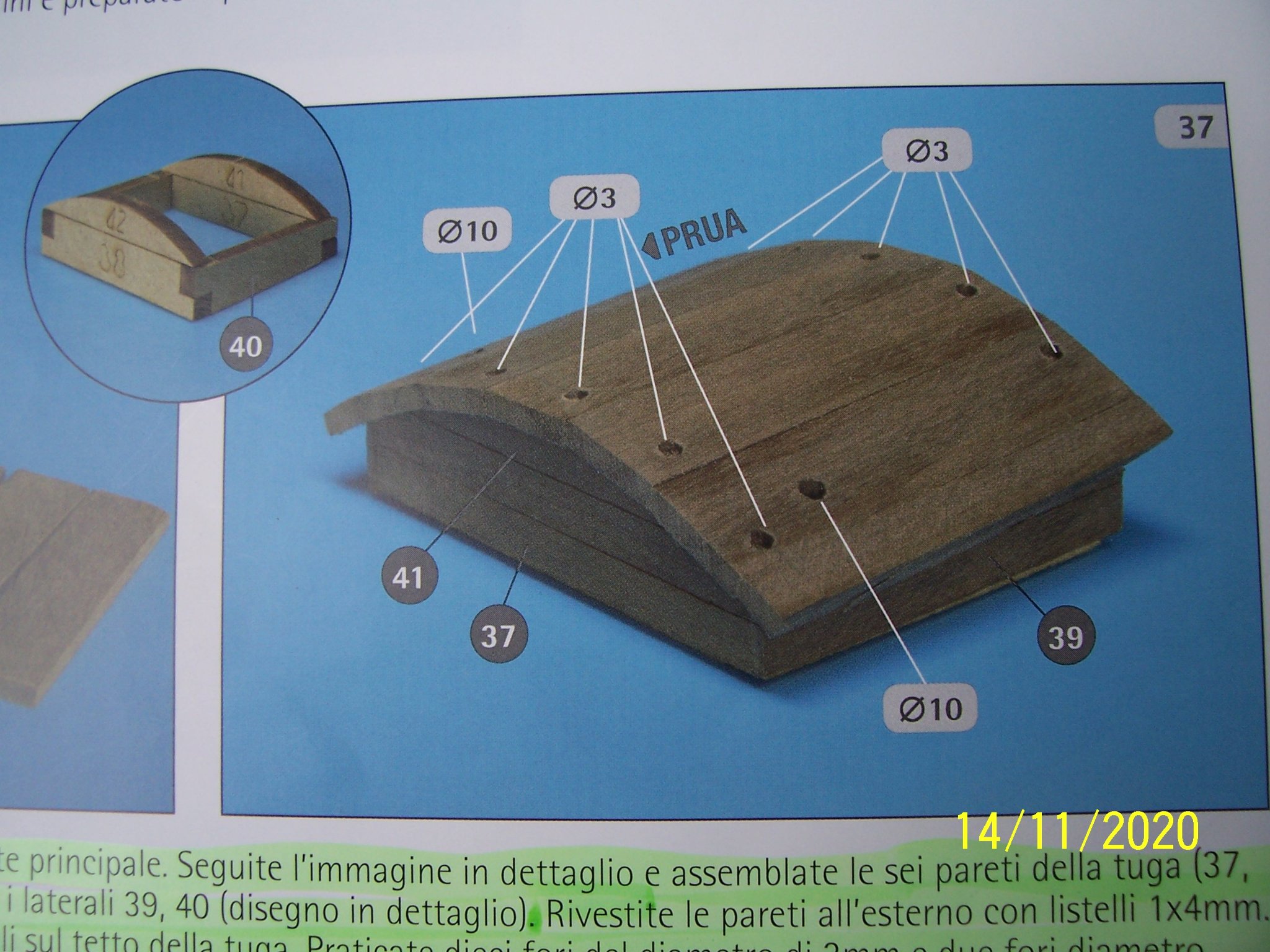
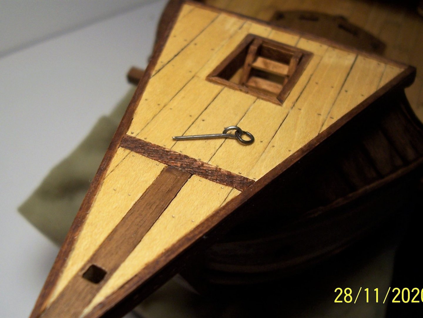
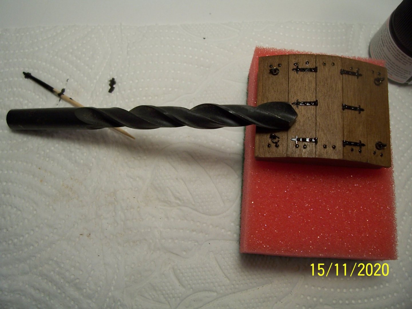
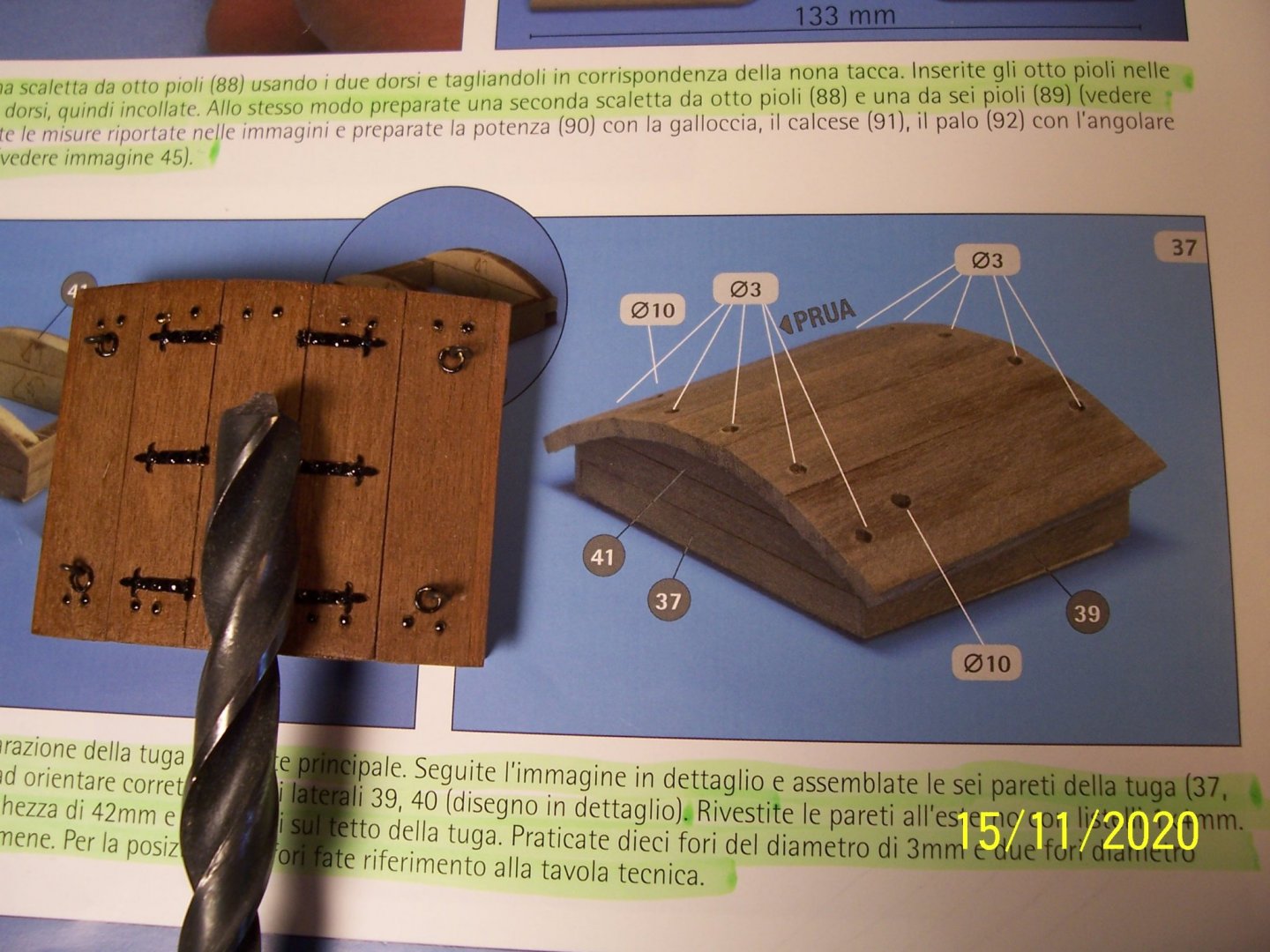
Thanks, Chuck. in my opinion, reading instructions and looking at the figures, it seems that the holes are just simple holes: The two major ones have been made for the passage of the anchors ropes and the others (maybe) for ventilation: But the Nao of Matarò has no hole on the roof of the deckhouse. Moreover, the hole with a diameter of 10 mm clearly seems to me a mistake: it would be too big, as shown in the photos with a 10 mm drill bit: They seem to me having a diameter about 4 or 5 mm. Rodolfo


-
Thanks Louie, now it's time for the main deckhouse. I made it at the beginning of the building. AMATI suggests a simple object, very similar to the Coca of Matarò: But I'm not sure about the holes in the roof. In Pinterest I saw a very nice ship and i tried to copy it: Next works: rack with cleat, mast hound, pole and bracket. See you later! Rodolfo