xodar461
-
Posts
172 -
Joined
-
Last visited
1 Follower

About xodar461

Recent Profile Visitors
2,761 profile views


-
 Egilman reacted to a post in a topic:
Foss Landing and The shipyard at Foss Landing by xodar461 - Sierra West Scale Models - 1/87
Egilman reacted to a post in a topic:
Foss Landing and The shipyard at Foss Landing by xodar461 - Sierra West Scale Models - 1/87
-
FriedClams reacted to a post in a topic:
Foss Landing and The shipyard at Foss Landing by xodar461 - Sierra West Scale Models - 1/87
-
 king derelict reacted to a post in a topic:
Foss Landing and The shipyard at Foss Landing by xodar461 - Sierra West Scale Models - 1/87
king derelict reacted to a post in a topic:
Foss Landing and The shipyard at Foss Landing by xodar461 - Sierra West Scale Models - 1/87
-
gjdale reacted to a post in a topic:
Foss Landing and The shipyard at Foss Landing by xodar461 - Sierra West Scale Models - 1/87
-
Old Collingwood reacted to a post in a topic:
Foss Landing and The shipyard at Foss Landing by xodar461 - Sierra West Scale Models - 1/87
-
Jack12477 reacted to a post in a topic:
Foss Landing and The shipyard at Foss Landing by xodar461 - Sierra West Scale Models - 1/87
-
Canute reacted to a post in a topic:
Foss Landing and The shipyard at Foss Landing by xodar461 - Sierra West Scale Models - 1/87
-
BLACK VIKING reacted to a post in a topic:
Foss Landing and The shipyard at Foss Landing by xodar461 - Sierra West Scale Models - 1/87
-
wefalck reacted to a post in a topic:
Foss Landing and The shipyard at Foss Landing by xodar461 - Sierra West Scale Models - 1/87
-
JacquesCousteau reacted to a post in a topic:
Foss Landing and The shipyard at Foss Landing by xodar461 - Sierra West Scale Models - 1/87
-
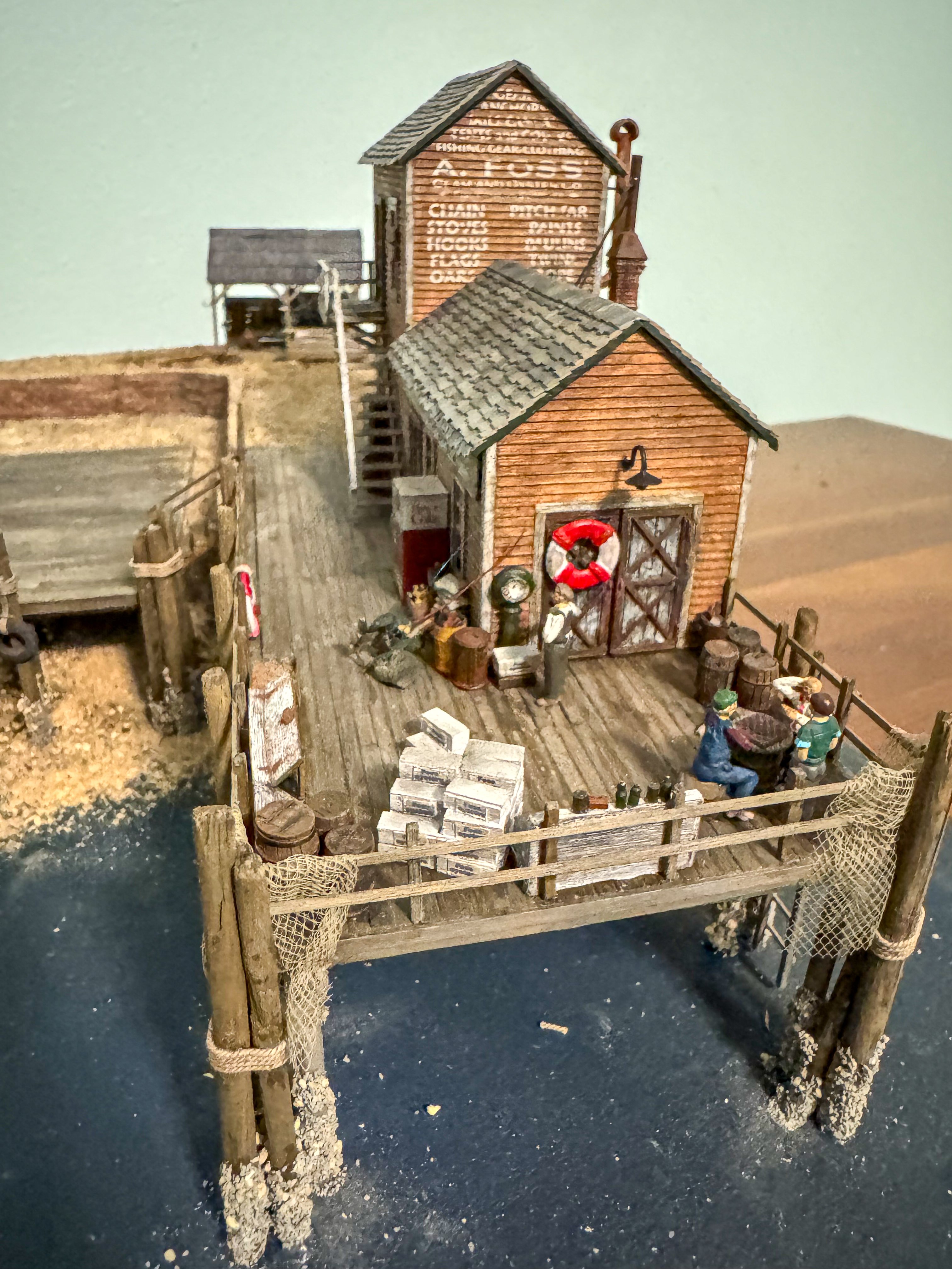
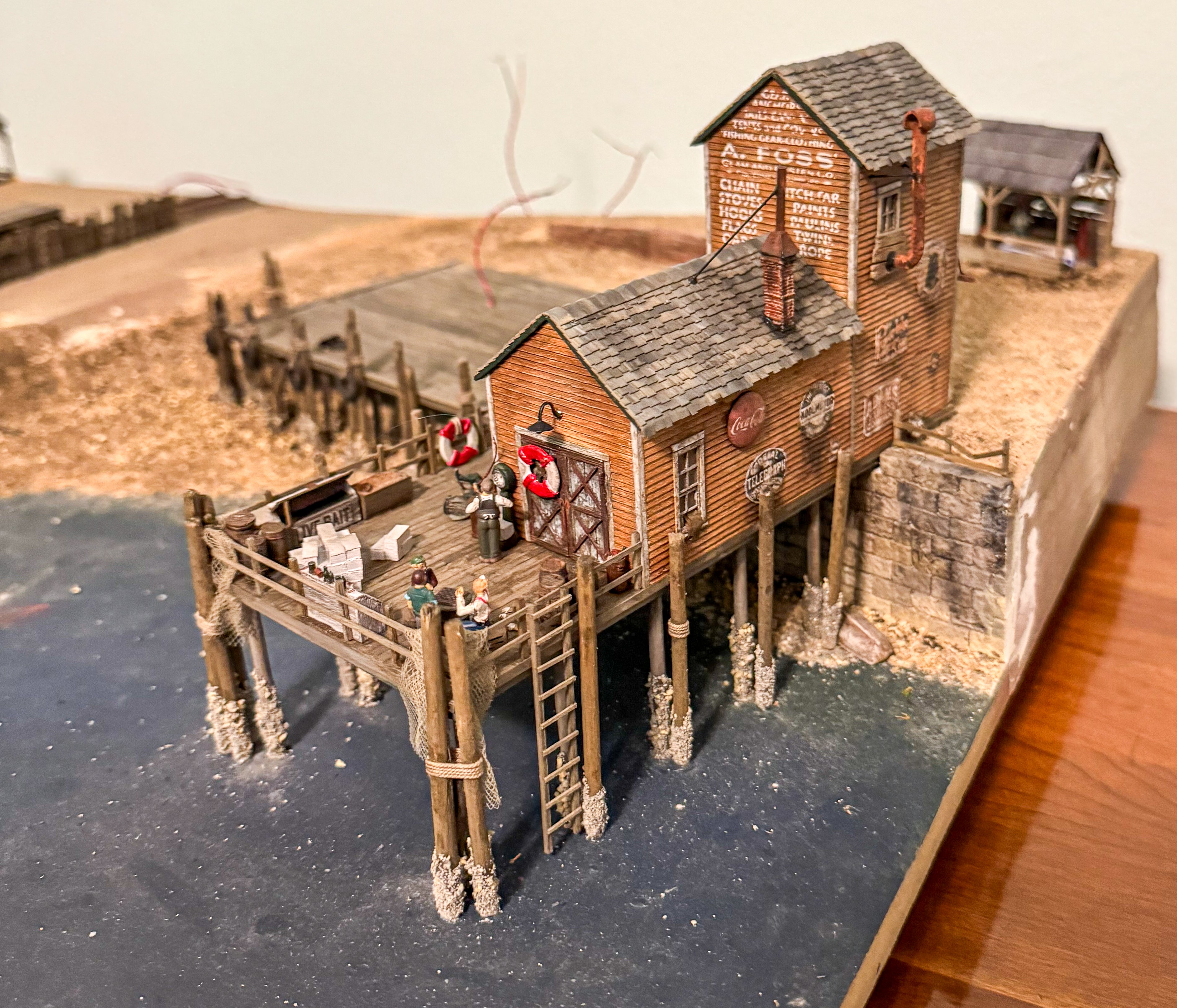
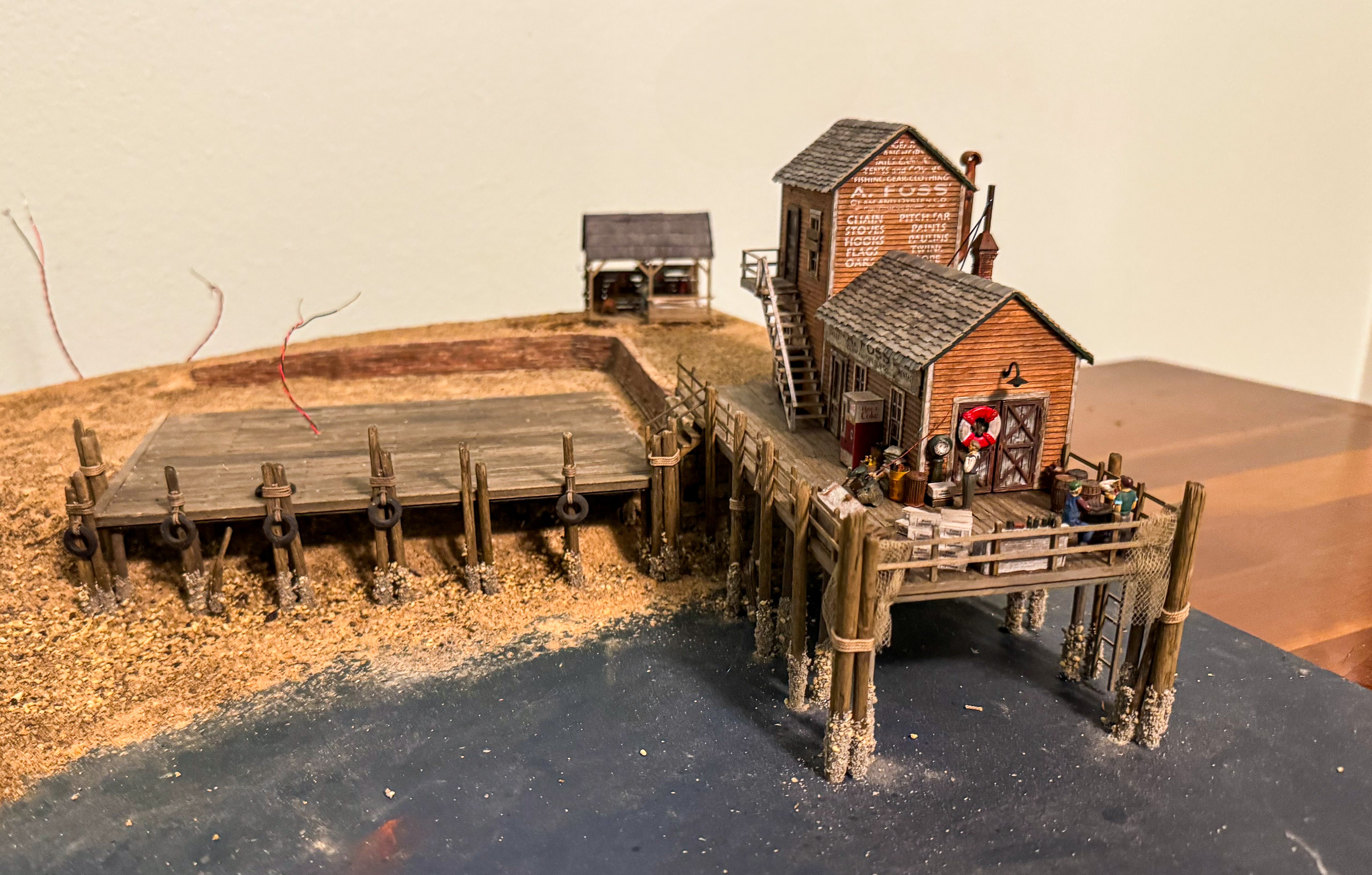
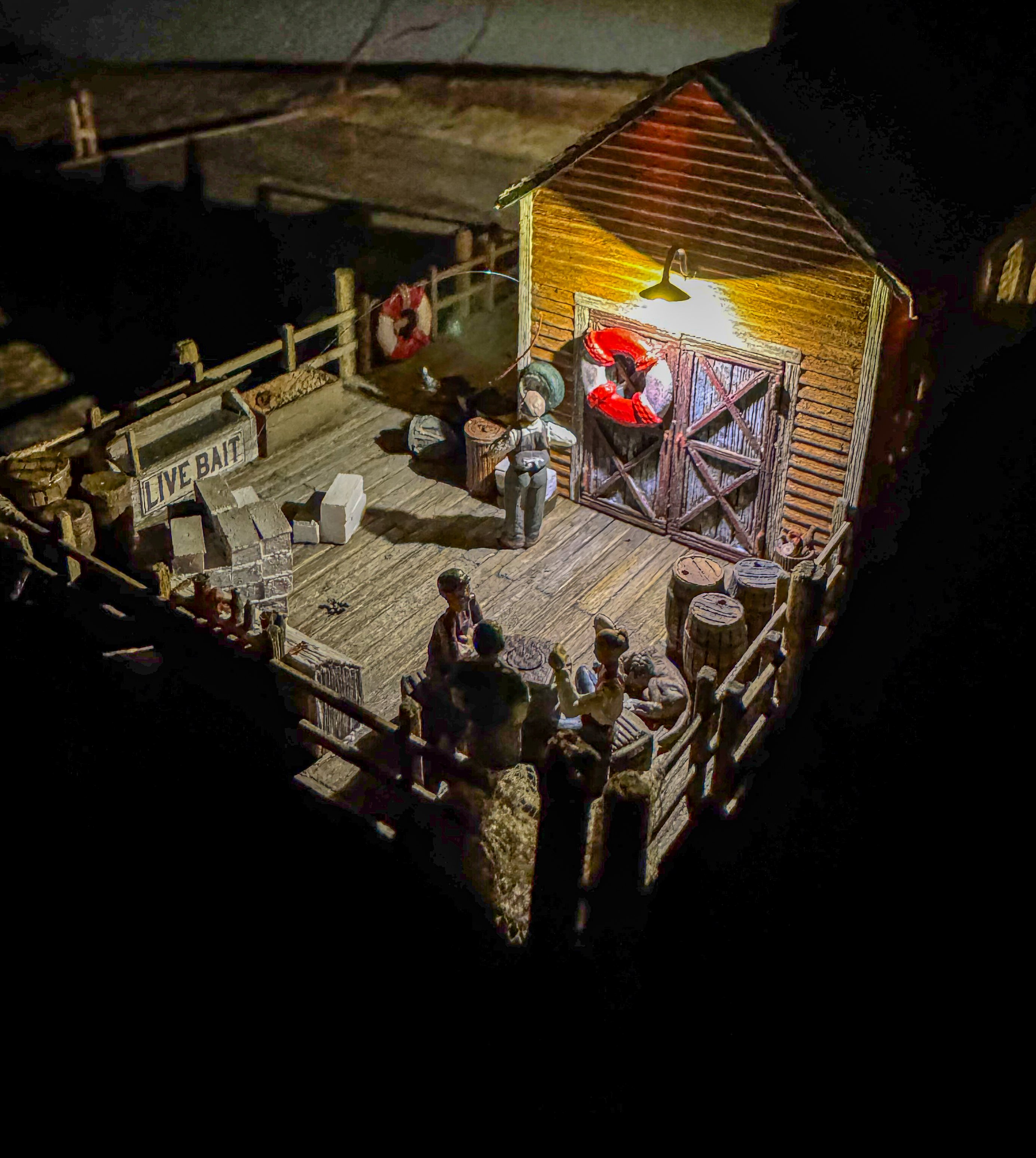
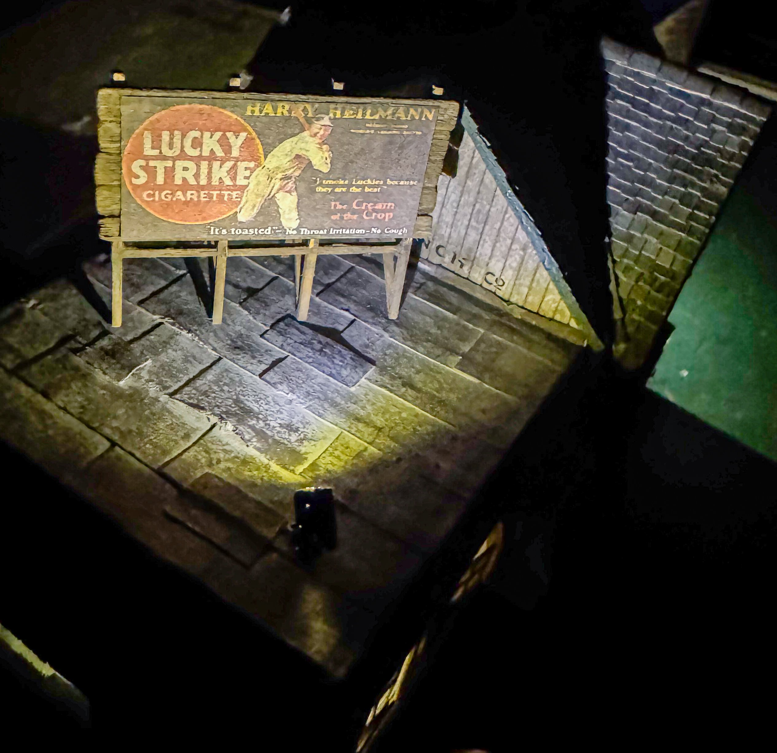
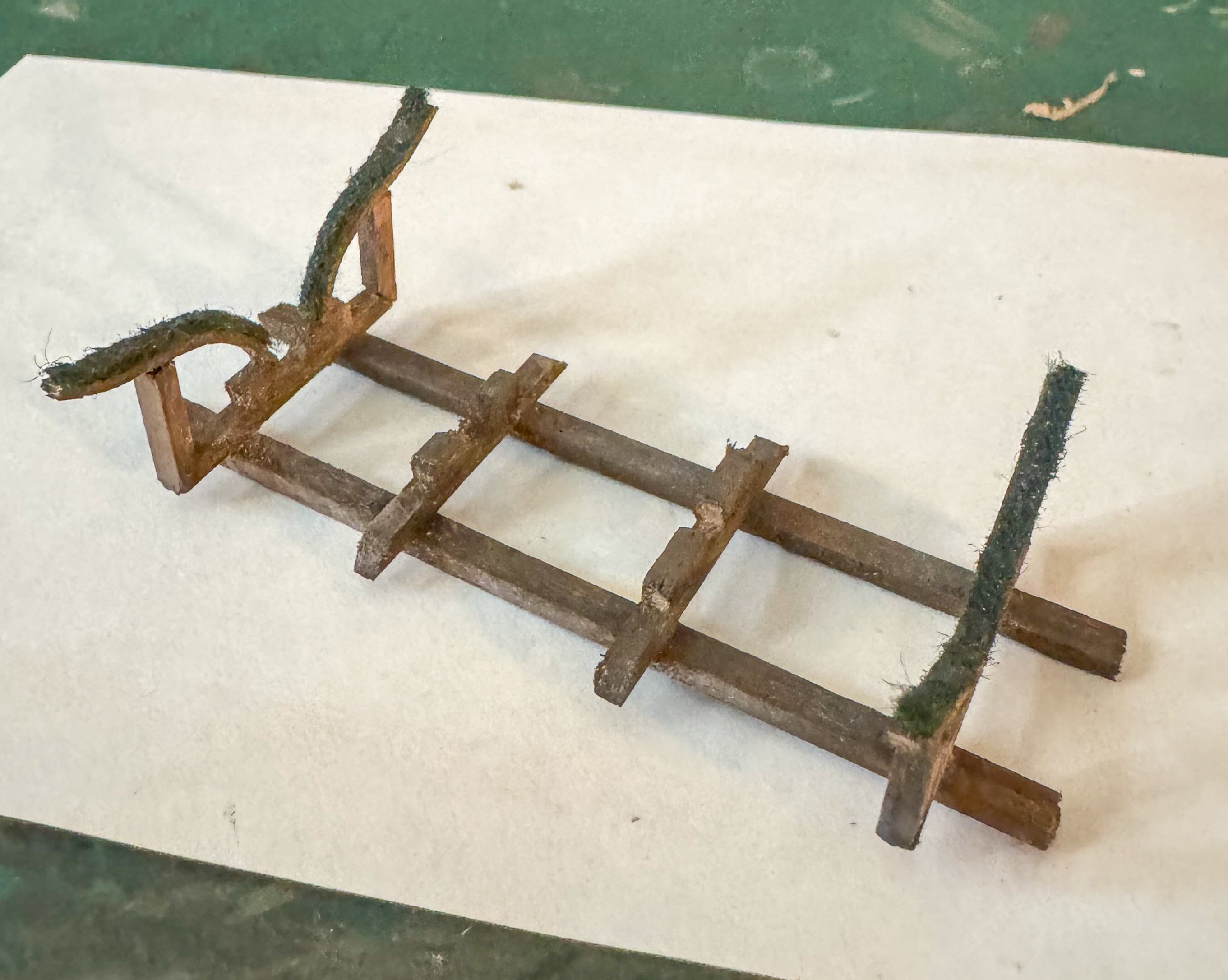
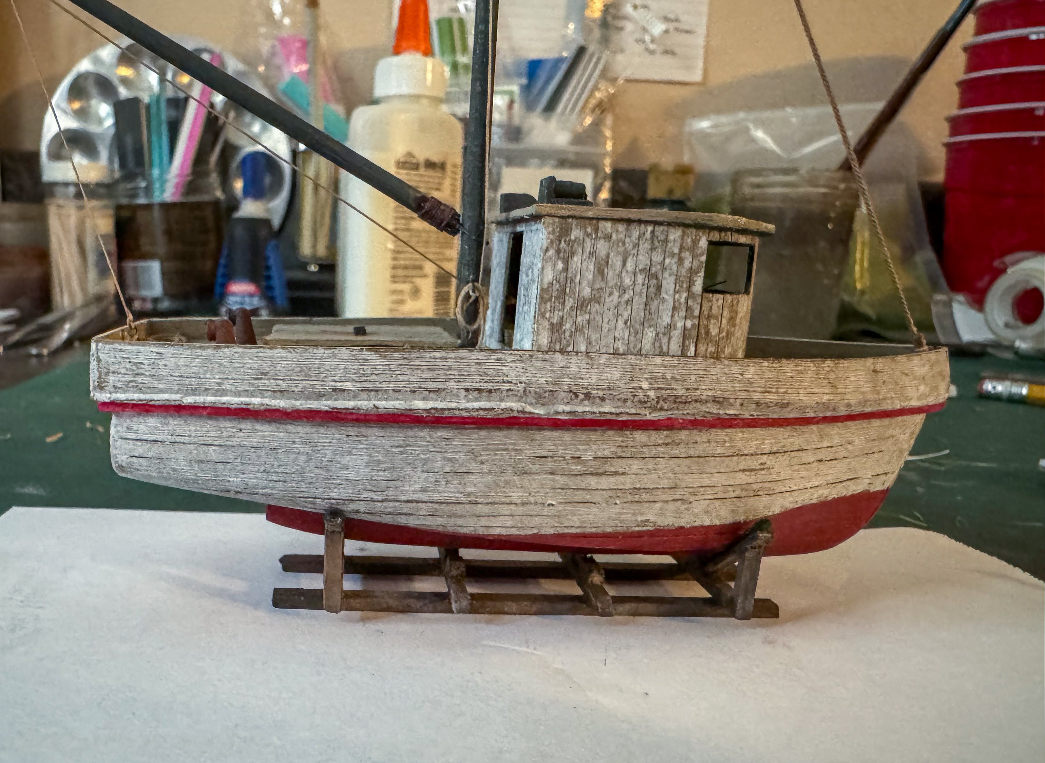
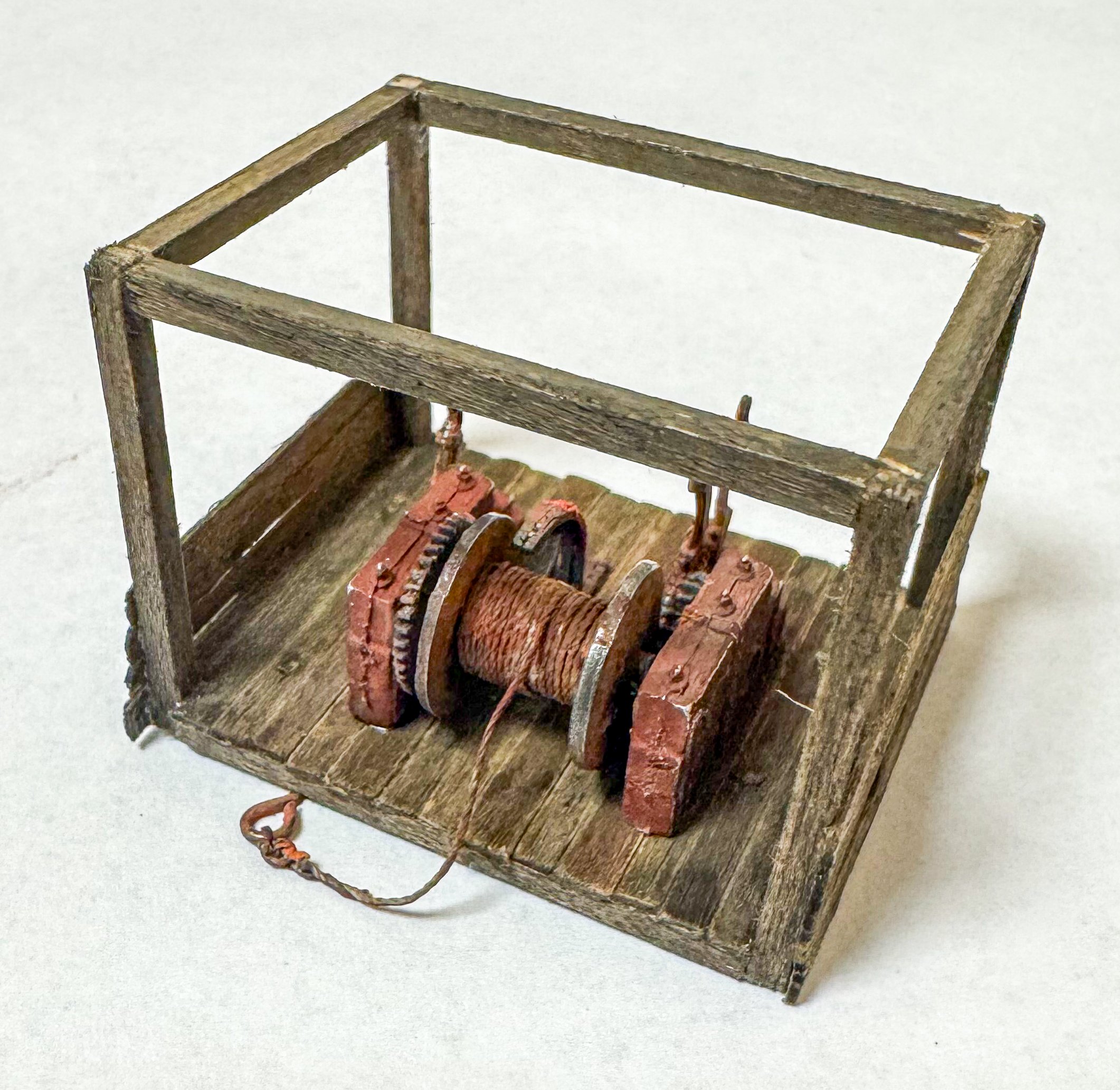
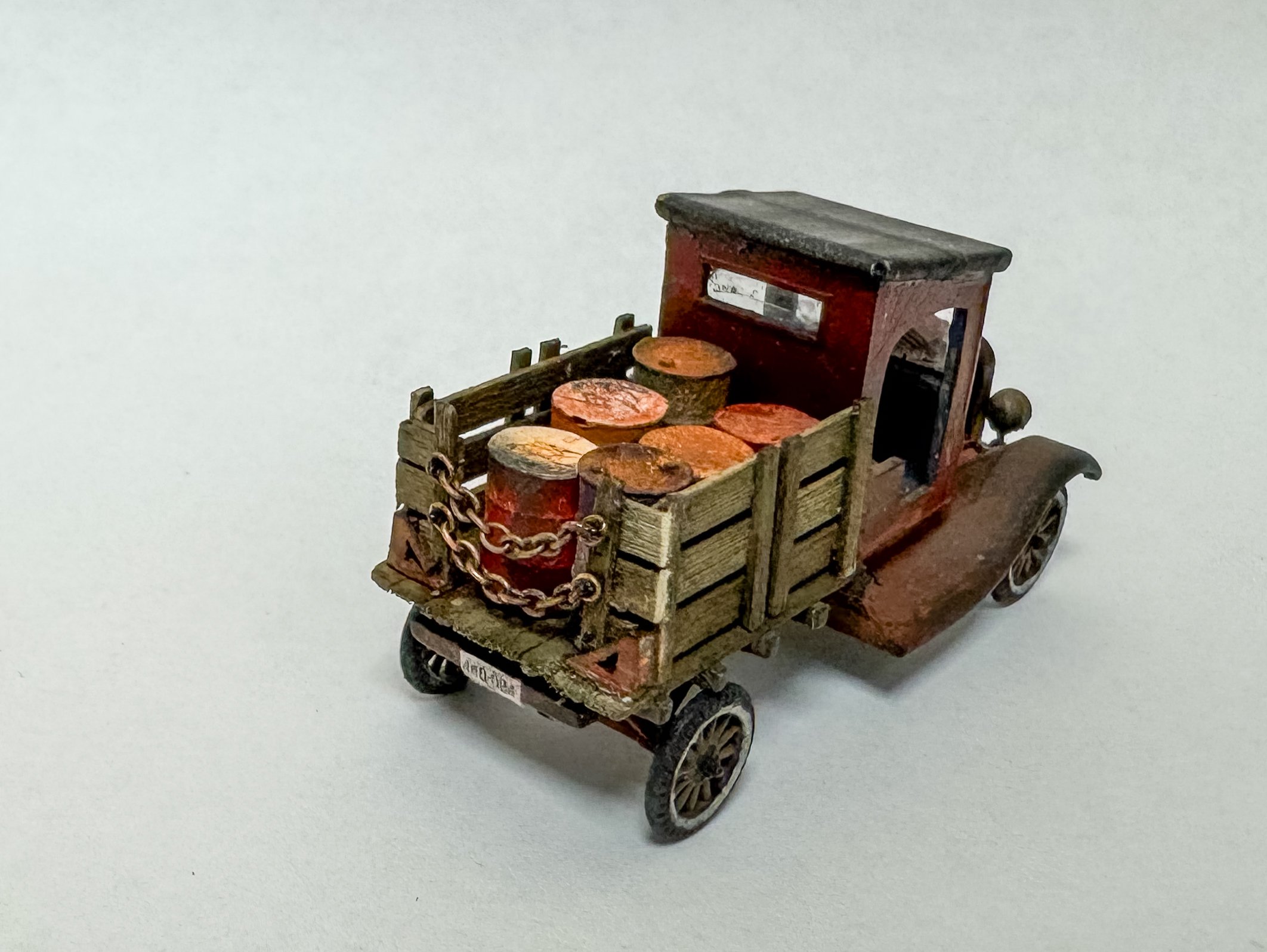
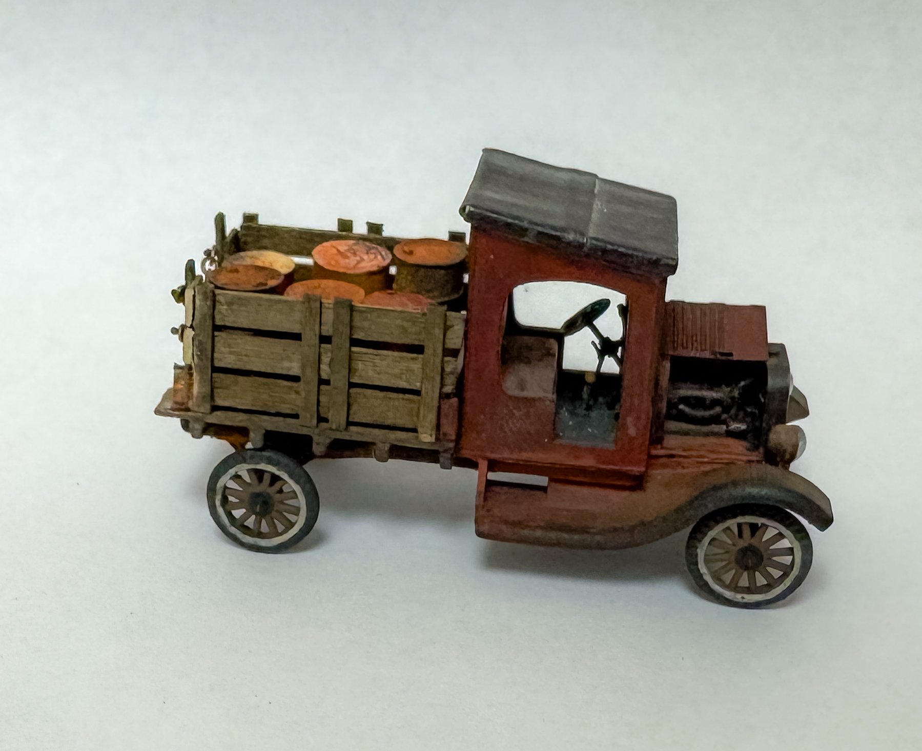
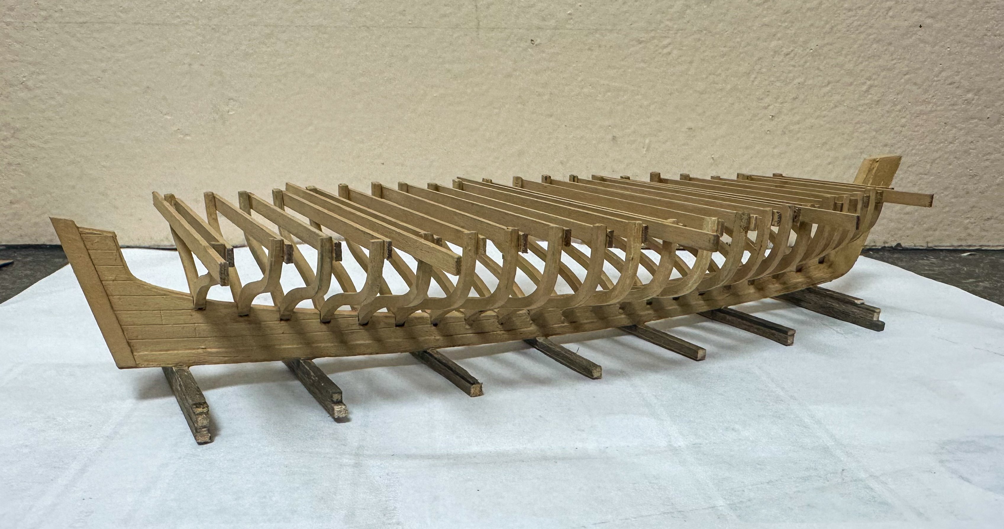
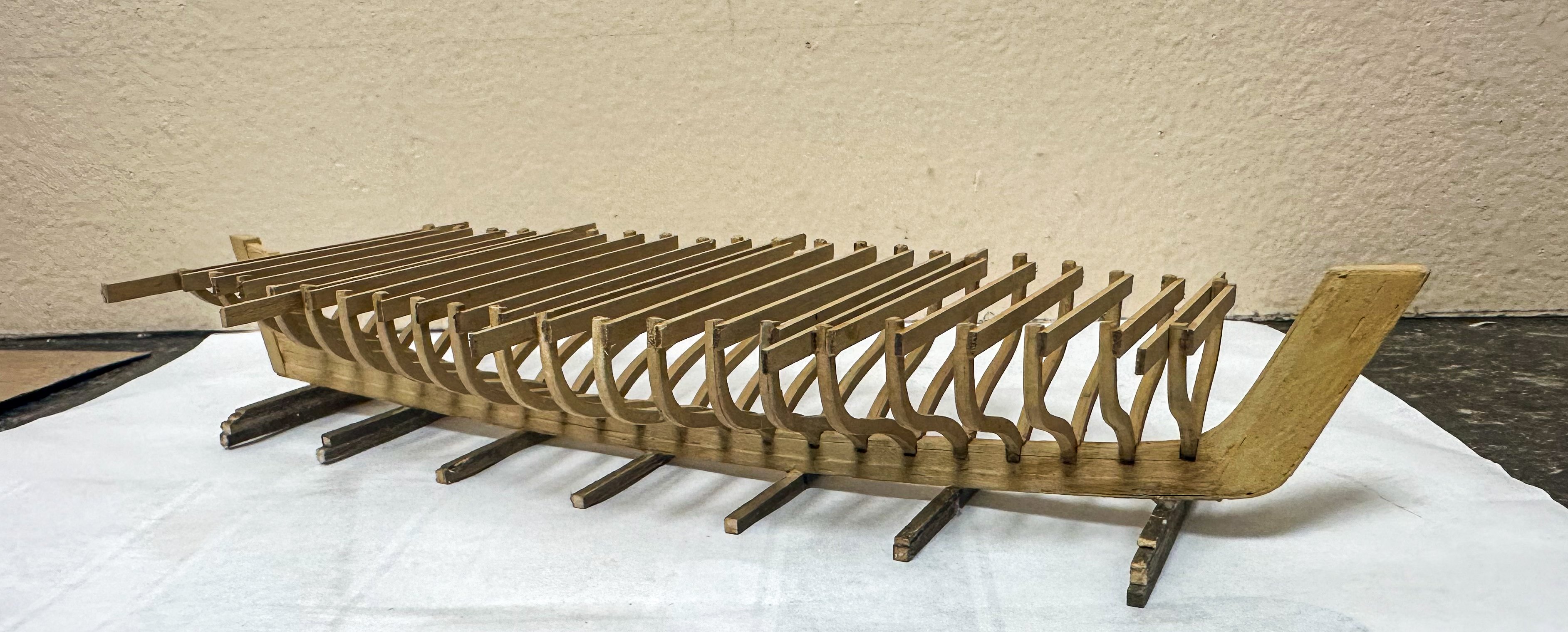
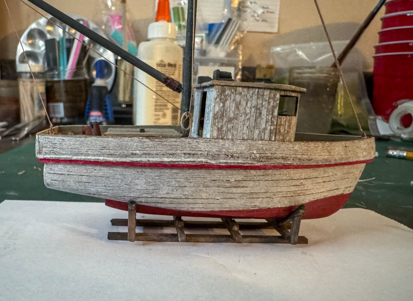
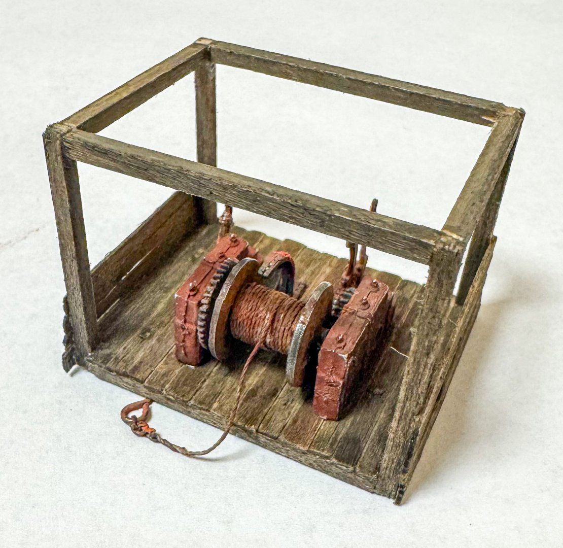
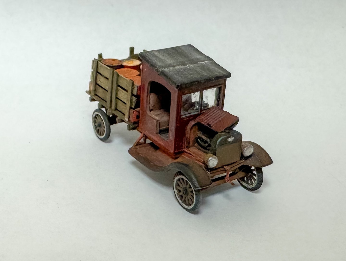
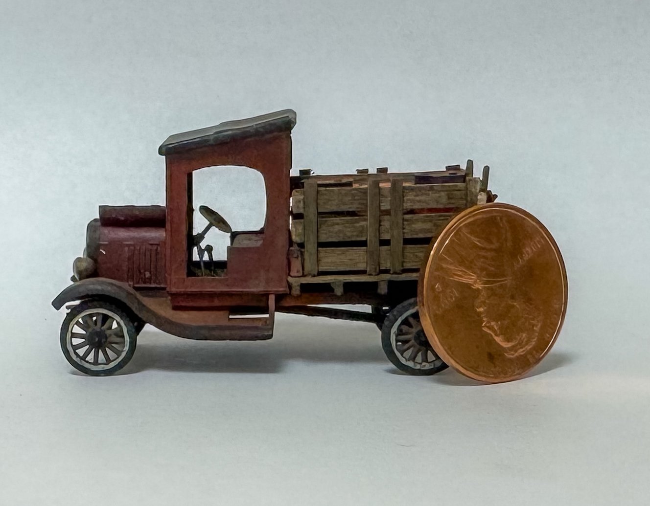
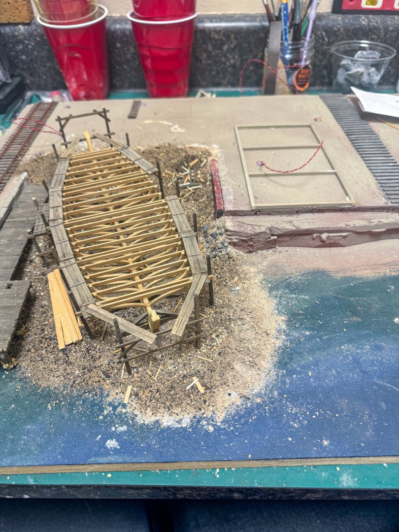
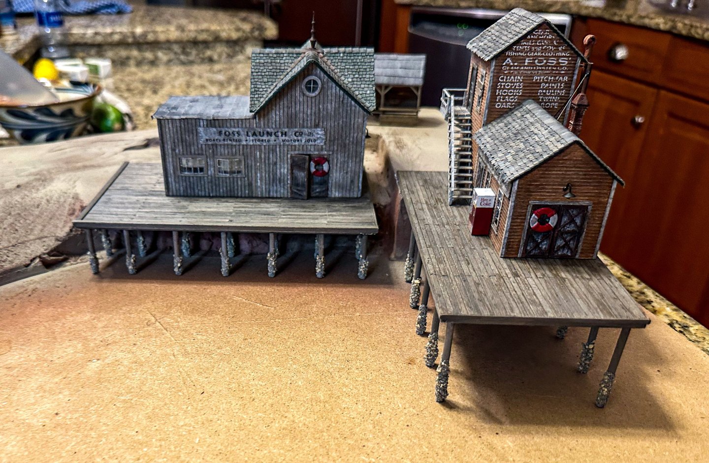
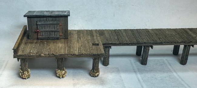
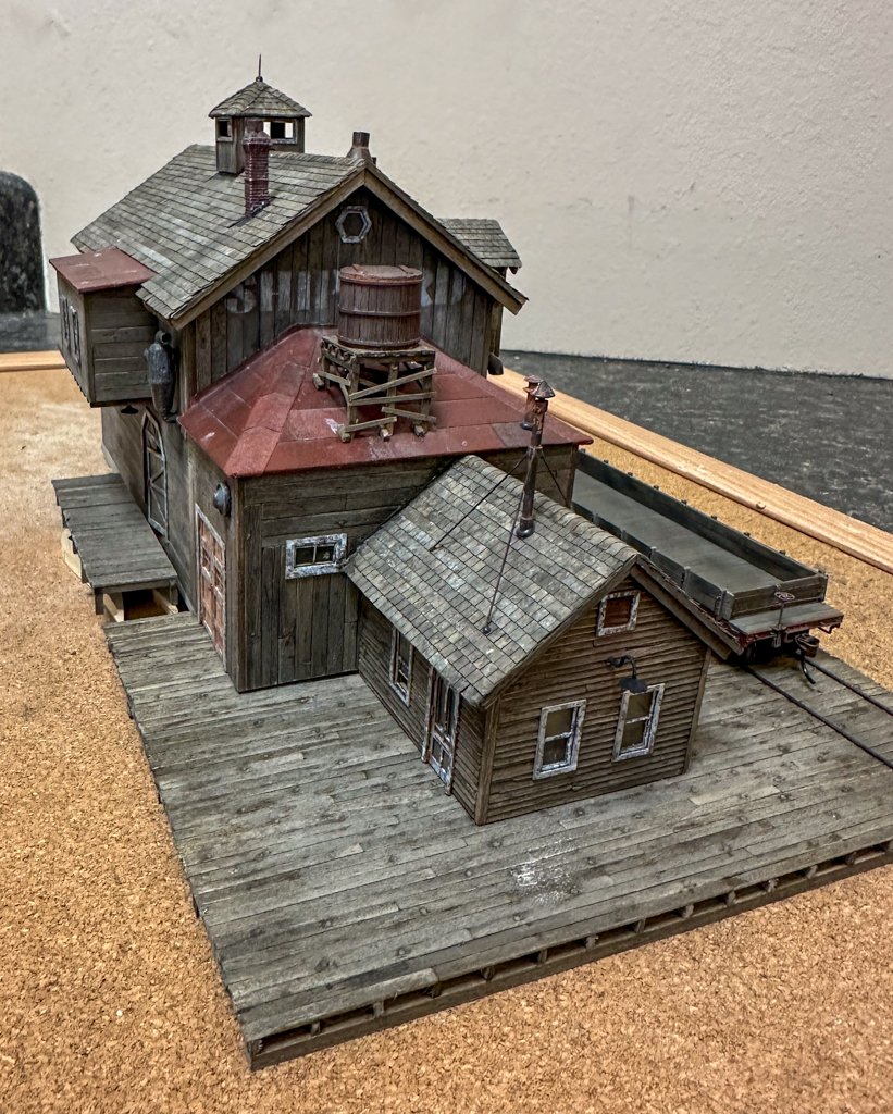
 Greetings! Back at it again. Time to start putting it all together. Before getting to the boat, I decided to glue the Oyster Co building to the dock and place the rowboat shed. Some items were placed on the dock (barrels, trash cans etc.). As this kit did not come with the decals for the oyster crates or the bait boxes, I printed some up and reduced them in size, a lot. There is also a fisherman on his back that will be eventually placed by the broken fence to the right of the building. As I envisioned the Oyster Co being a place to gather socially, there is also a group of figures at the front of the dock, 2 of whom are playing checkers. And now at night: A few photos of the rowboat shed: Some calendars from the paper decal sheet were placed on the wall by the work bench. The saw and utility sheds were also glued to the base. I also decided to wire up a spotlight for the billboard that will go on the roof of the Launch Co. On to my thoughts on the boat undergoing repairs. First question is how did it get up there? It would obviously be pretty heavy so I figured it would have to be pulled up somehow. Looking though some build logs here I came across Shelby's Marine. Here a boat is pulled up on trailer on tracks by a winch. Since I wanted this to an informal repair area, I decided to use some spare RR ties and make a wooden launch ramp and build a trailer for the boat. Here's a photo of the trailer and boat resting on it. green felt was added to the contact points of the boat to simulate protective bolsters. Wheels were added and we now have a boat trailer. But what to pull it up with? I was able to find a winch kit and so, after it was painted and assembled, a housing was built for it. And finally, a few pics of the Sierra West Ford Model T truck. Amazing detail for HO scale! Scenery around the rowboat shed and along the brick wall is next. I would like the grounds around the Oyster and Launch Co to have some grass and bushes vs the Shipyard area which will be a bit more sparse. So, we will see how that turns out. I'll also have some photos on the wooden launch ramp. Jeff


- 87 replies
-
- 10
-
-
-
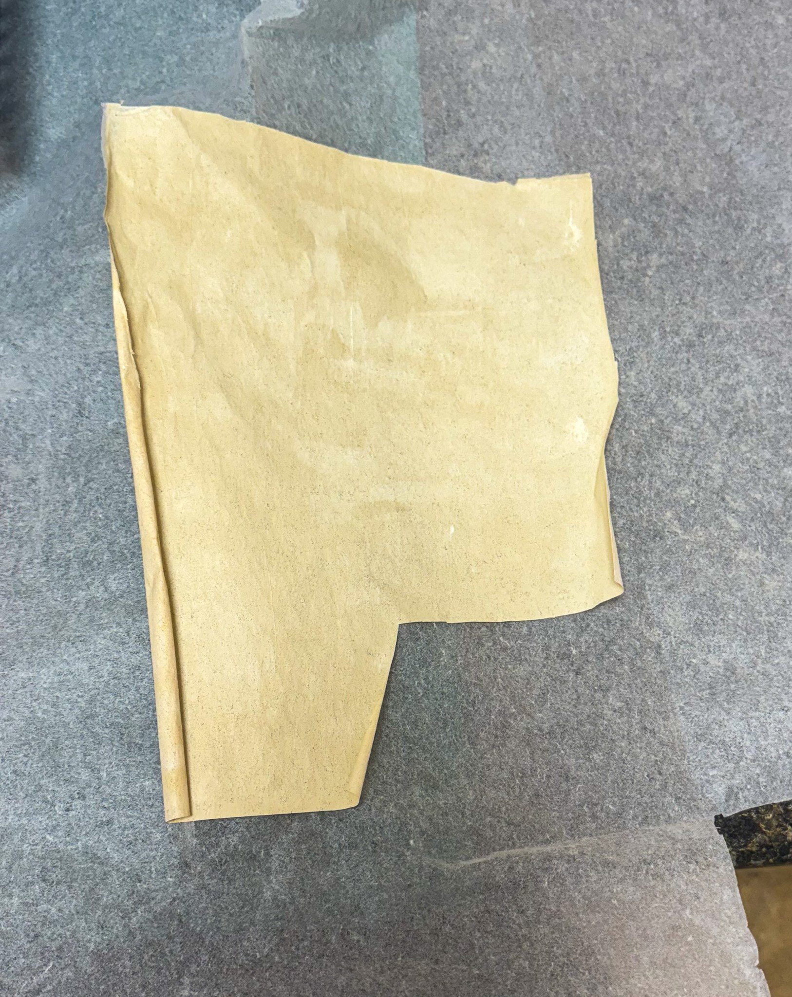
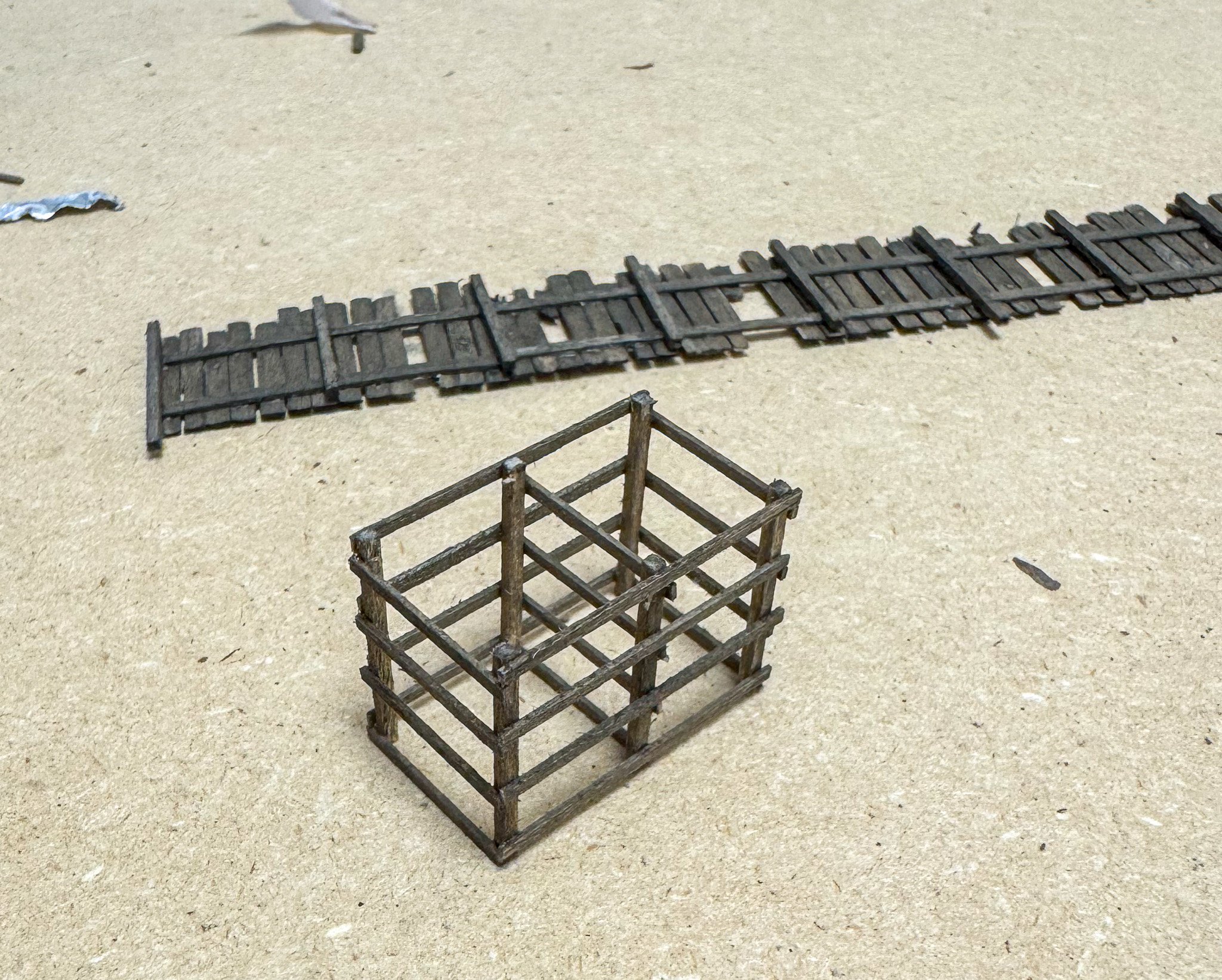
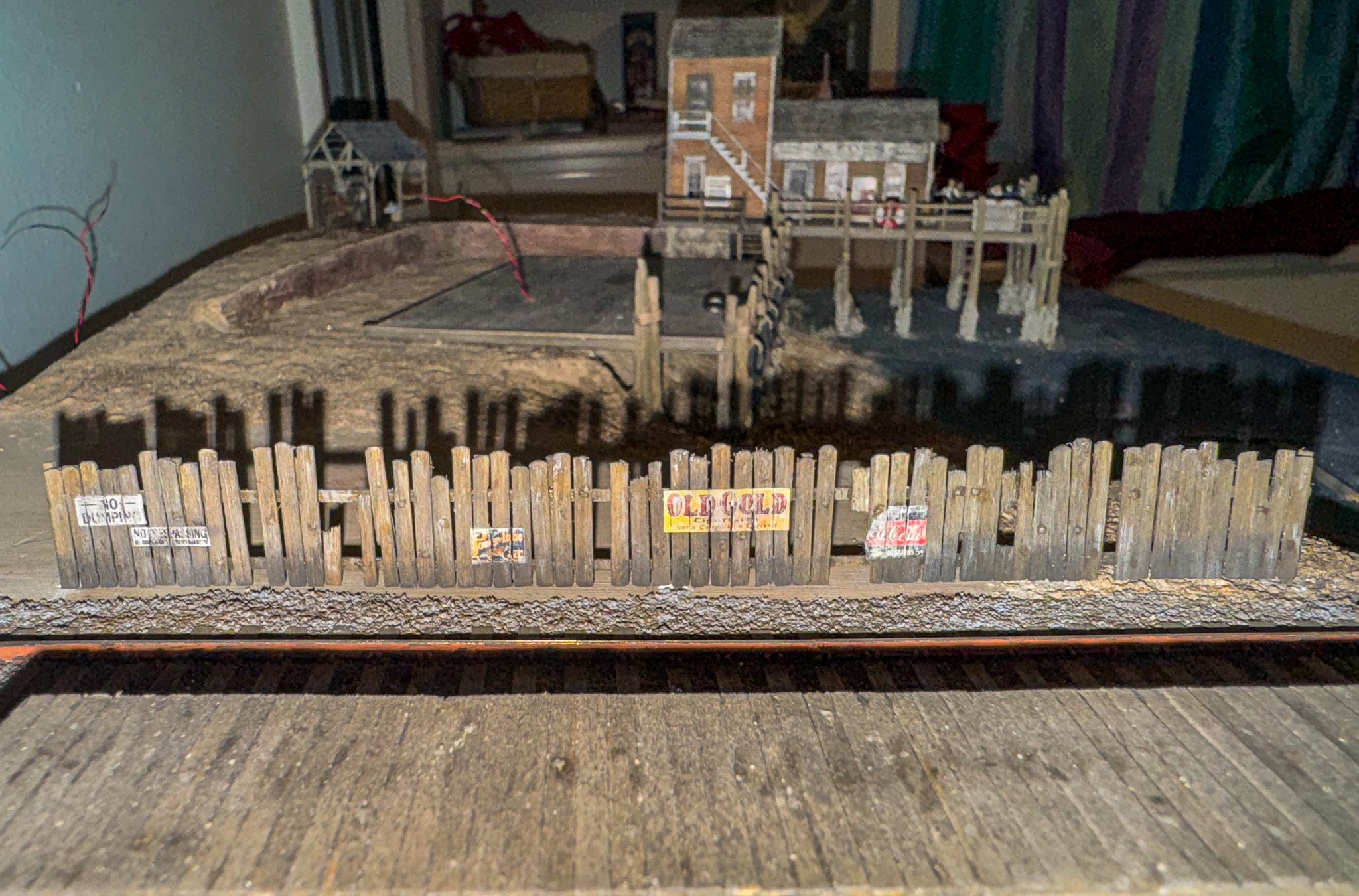
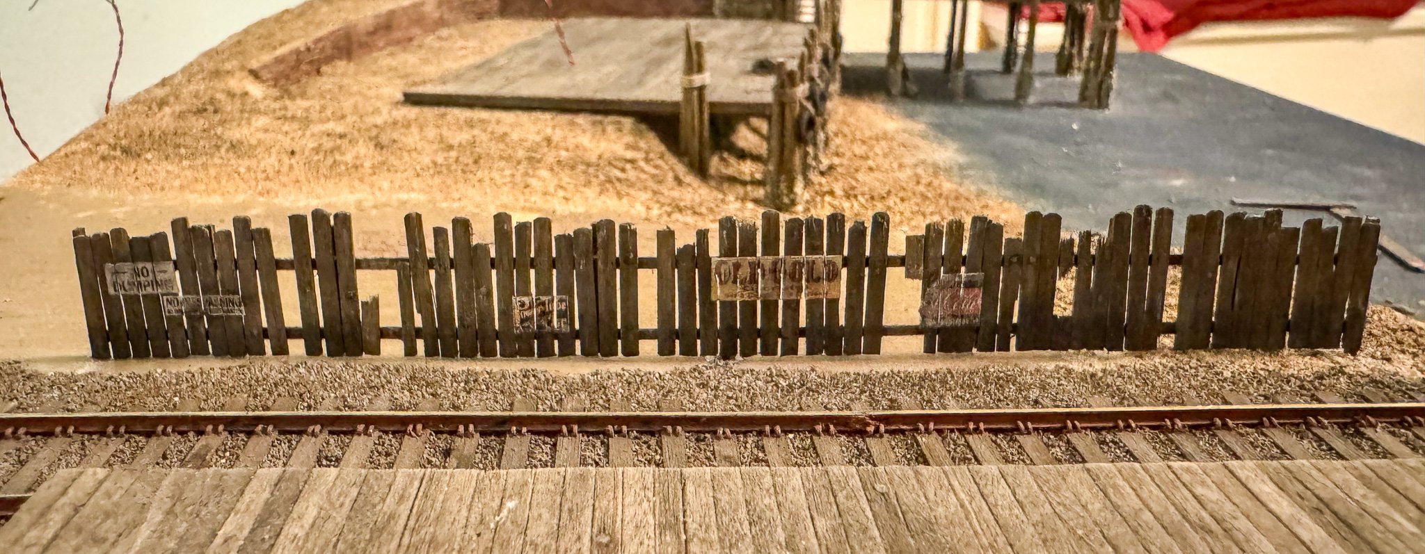
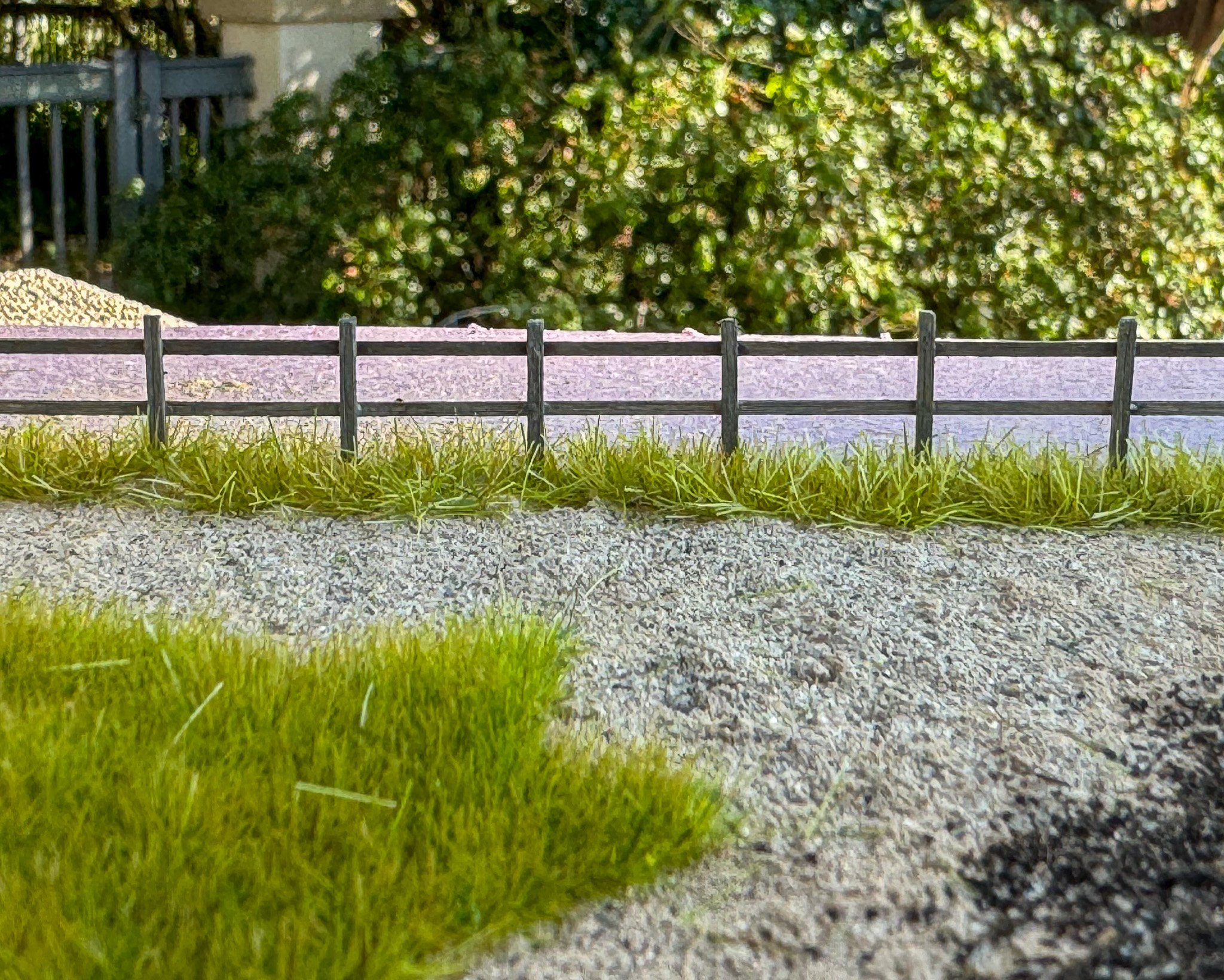
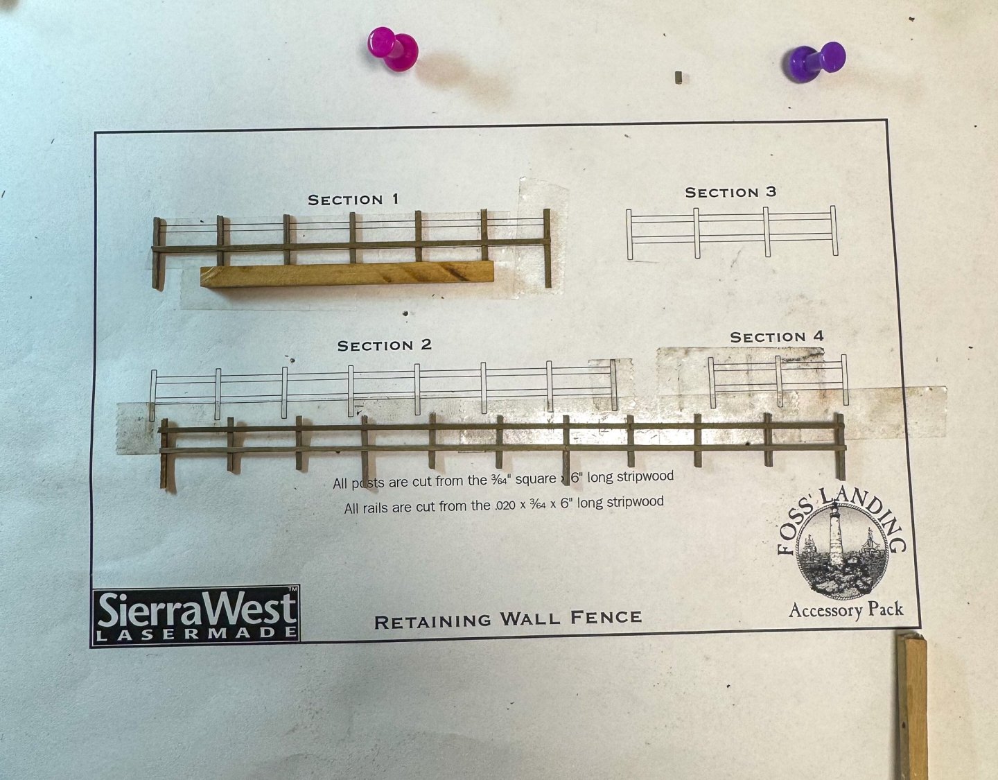
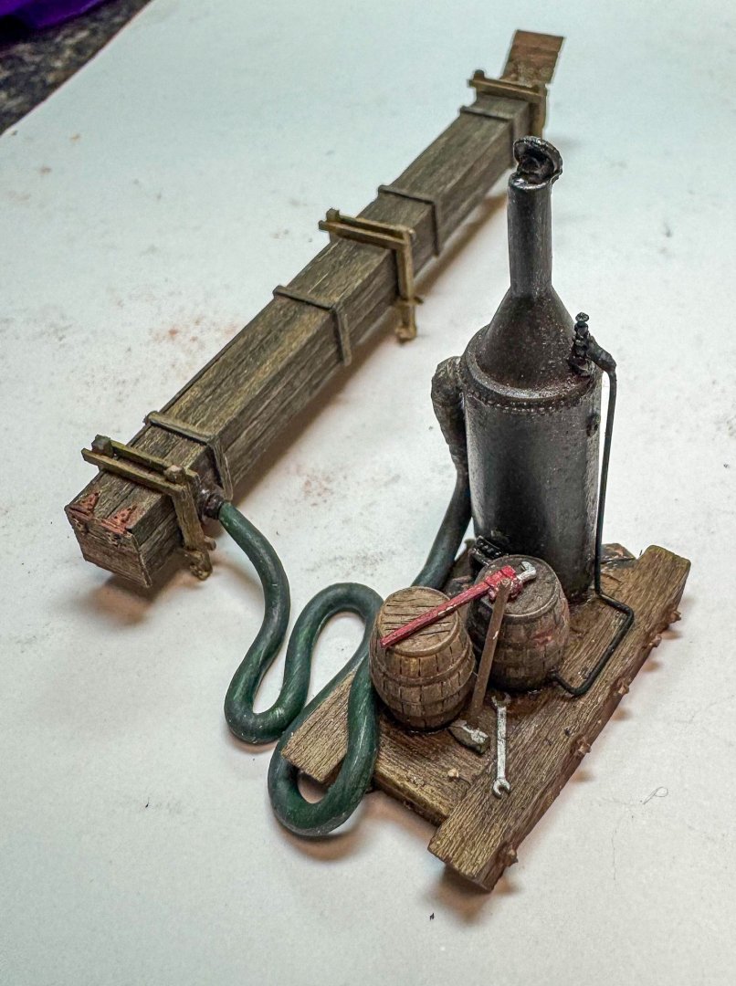
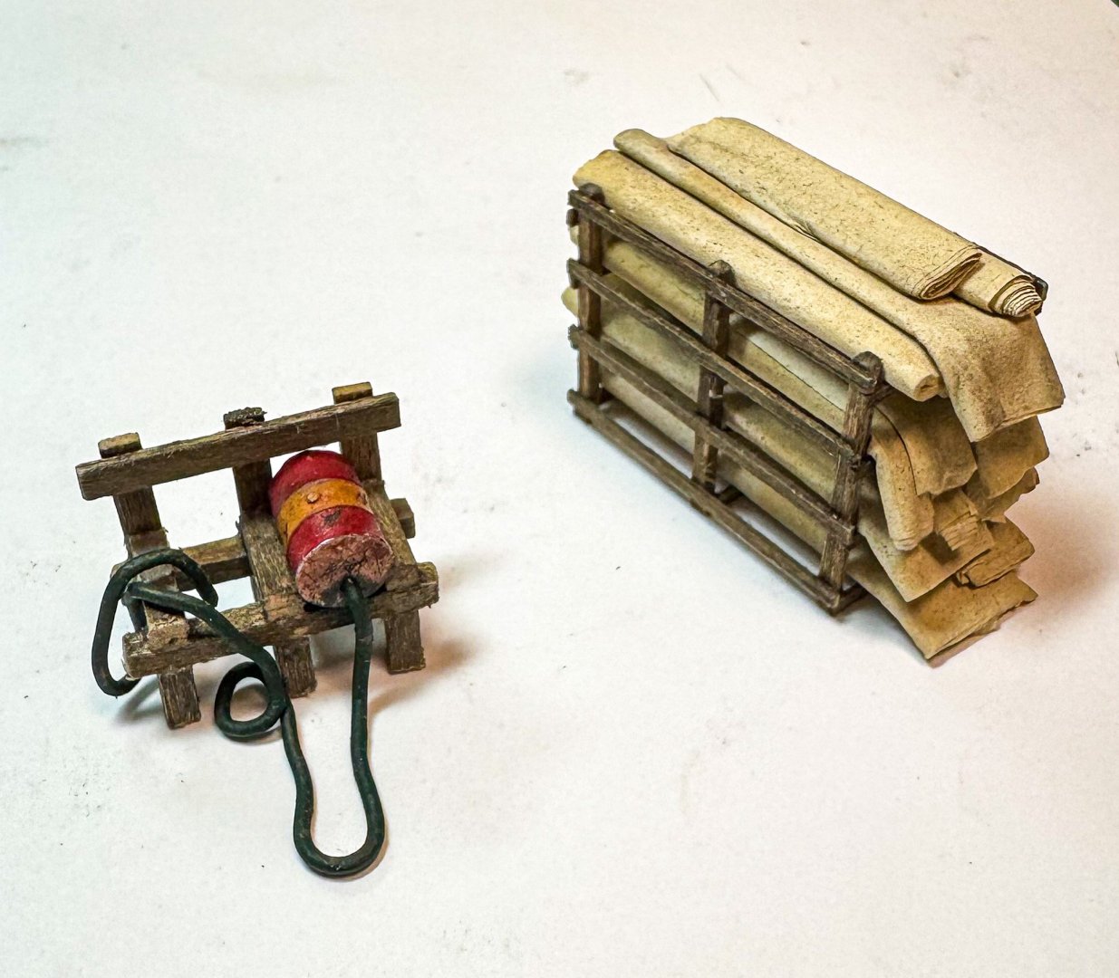
Greetings! It's been a while since my last update but construction continues. After the sculptamold and docks were placed, I decided to make some of the mini-kits included in the main kit, including the wooden fences (both Foss Landing and the shipyard), the steam box and boiler, canvas rack and the oil drum rack. For the simulated canvas, I used some leftover silkspan from my sail-making for the Revenge. The silkspan was first painted with an off white / light tan paint (leftover from some room in the house). Here is a photo of the white silkspan and the painted final product. Construction of the canvas rack was a bit fiddly given the very fine wood beams. The "canvas" was then rolled into a variety of sizes and placed in the rack. Also pictured above is the oil drum rack. The hose is a 1 mm brass wire which was annealed to soften it up so I could bend it to the shape seen. The steam box and boiler were fun to build. For the box doors, I used some leftover door hinges rather than the paper as suggested in the instructions. 2 mm solder was used for the boiler hose. The piping leading from a barrel to the boiler valve was interesting to fit. One suggestion for any future builders - attach the valve at the very end of construction as it is quite fine and will break off at the slightest pressure. The fences were straightforward however for the Foss Landing retaining wall fence, rather than several sections that step down, I made one longer section that will follow the slope of the brick wall. Note that several posts are longer so that they can be driven into the base, much like the boundary fence for the shipyard. The Shipyard fence is a bit different construction with vertical boards glued to horizontal stringers. This fence is heavily weathered with cracked and missing boards. I decided to use some of the Foss Landing paper advertising signs for the fence. Below are 2 photos, one with flash which highlights some features of the fence such as the darker bottom where the wood touches the ground. And lastly, I am starting to think about some of the landscaping around the buildings, fences and bare areas. I was thinking of using a product called static grass to give an effect of somewhat overgrown grass near the fence. The grass comes in different sizes and hues. I'm still experimenting but my thoughts are to have a bit of grass and shrubs near the Foss landing buildings, less so for the shipyard. Anyway, here is a photo of the Foss landing fence with some taller grass at the fence base. Shorter static grass can be seen in the foreground. Next up will be some thoughts on the boat which is undergoing repair at Foss landing and some photos of the first buildings placed on the base Jeff


- 87 replies
-
- 10
-
-
-
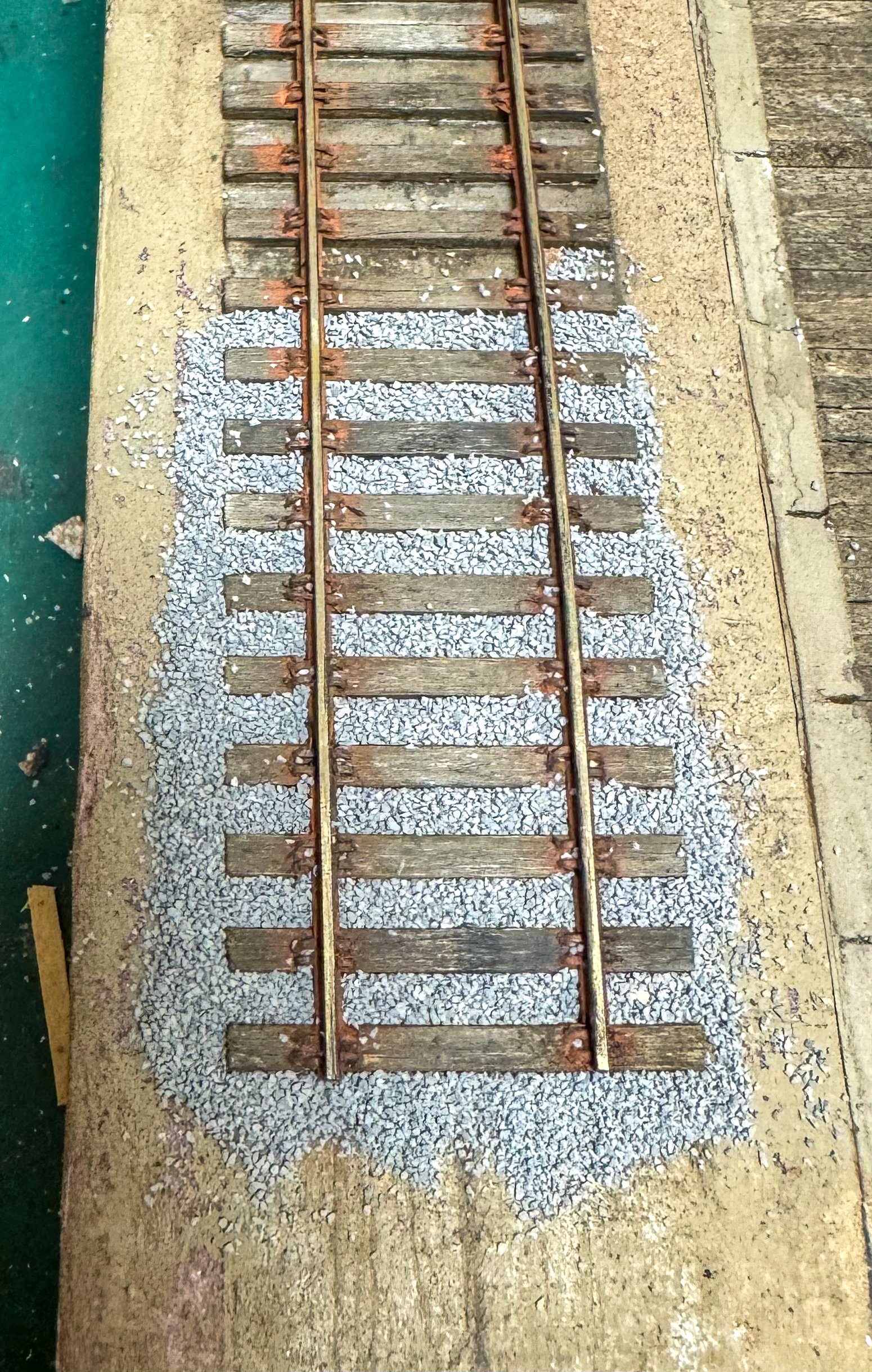
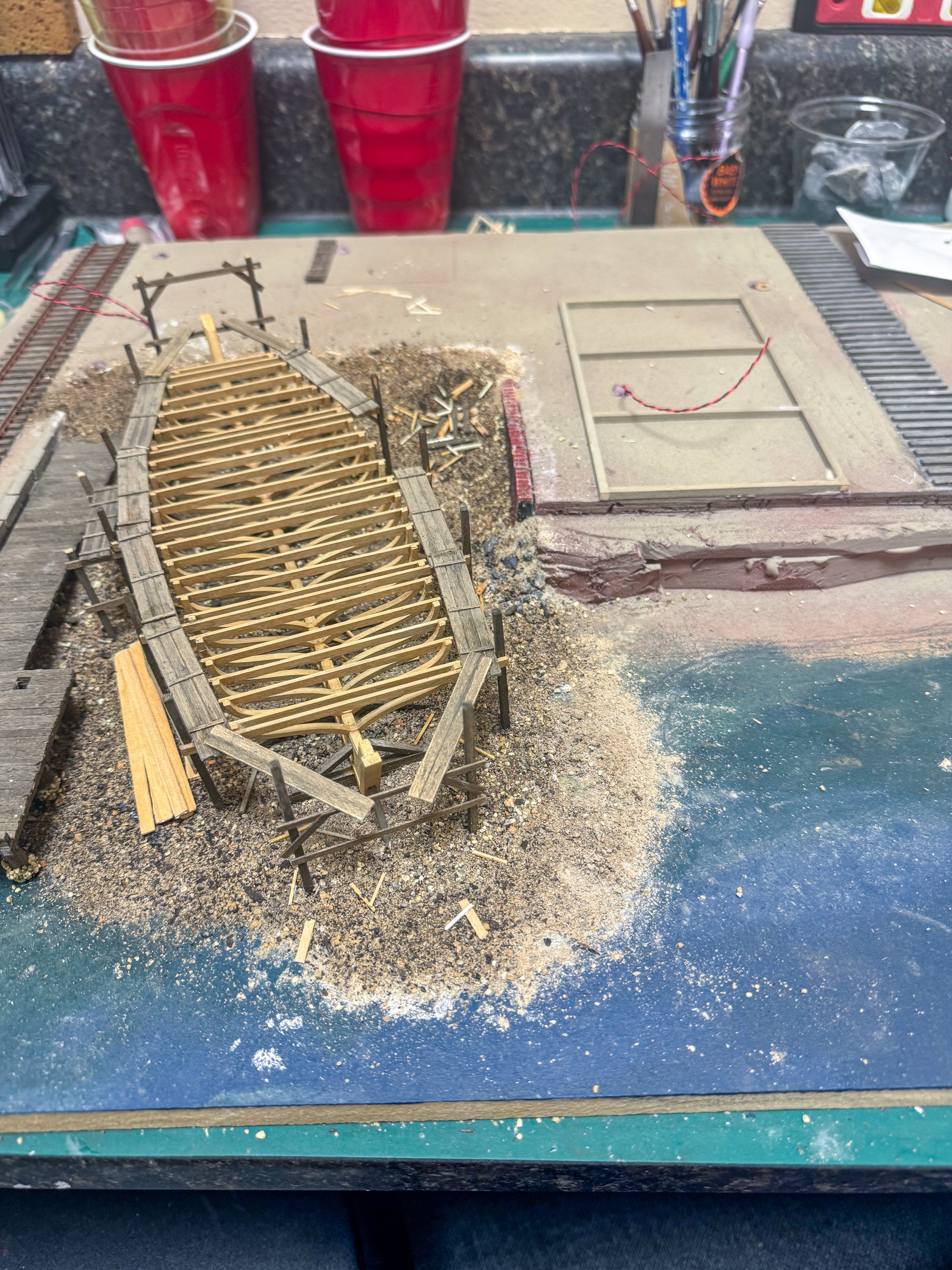
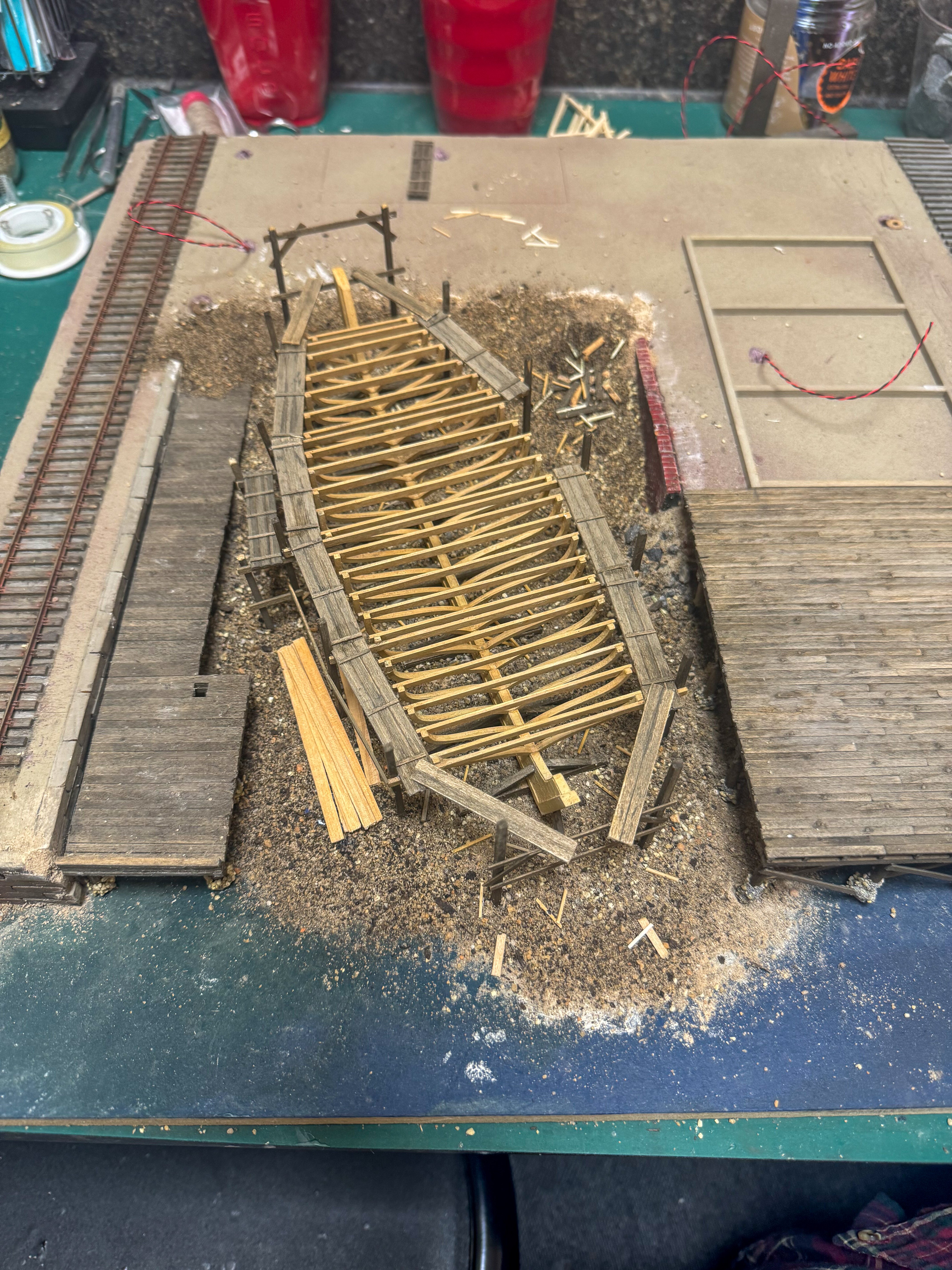
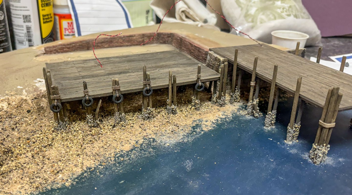
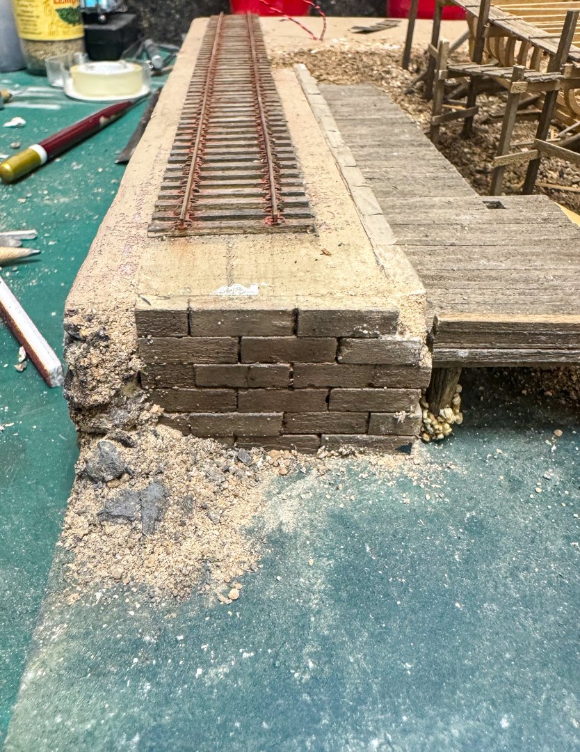
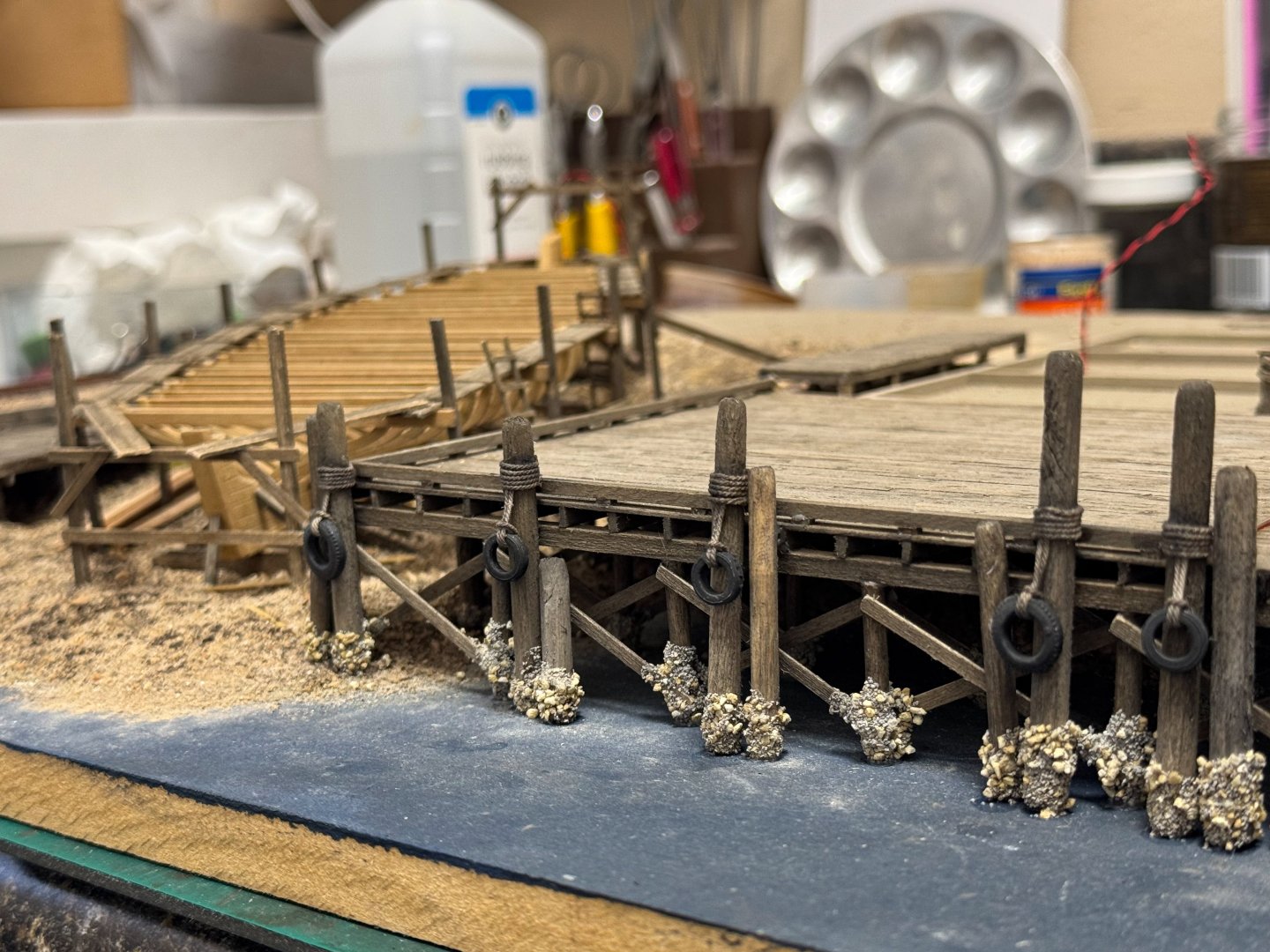
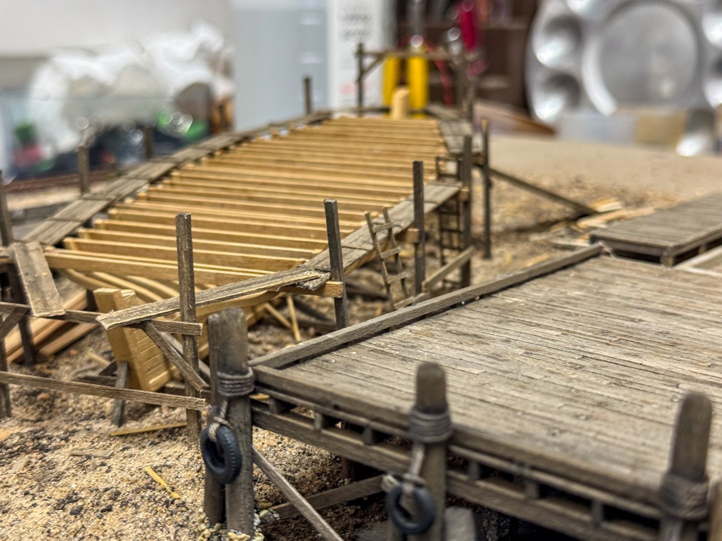
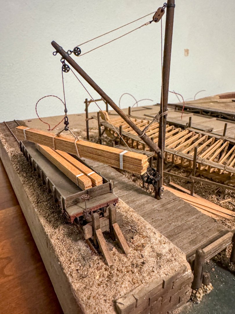
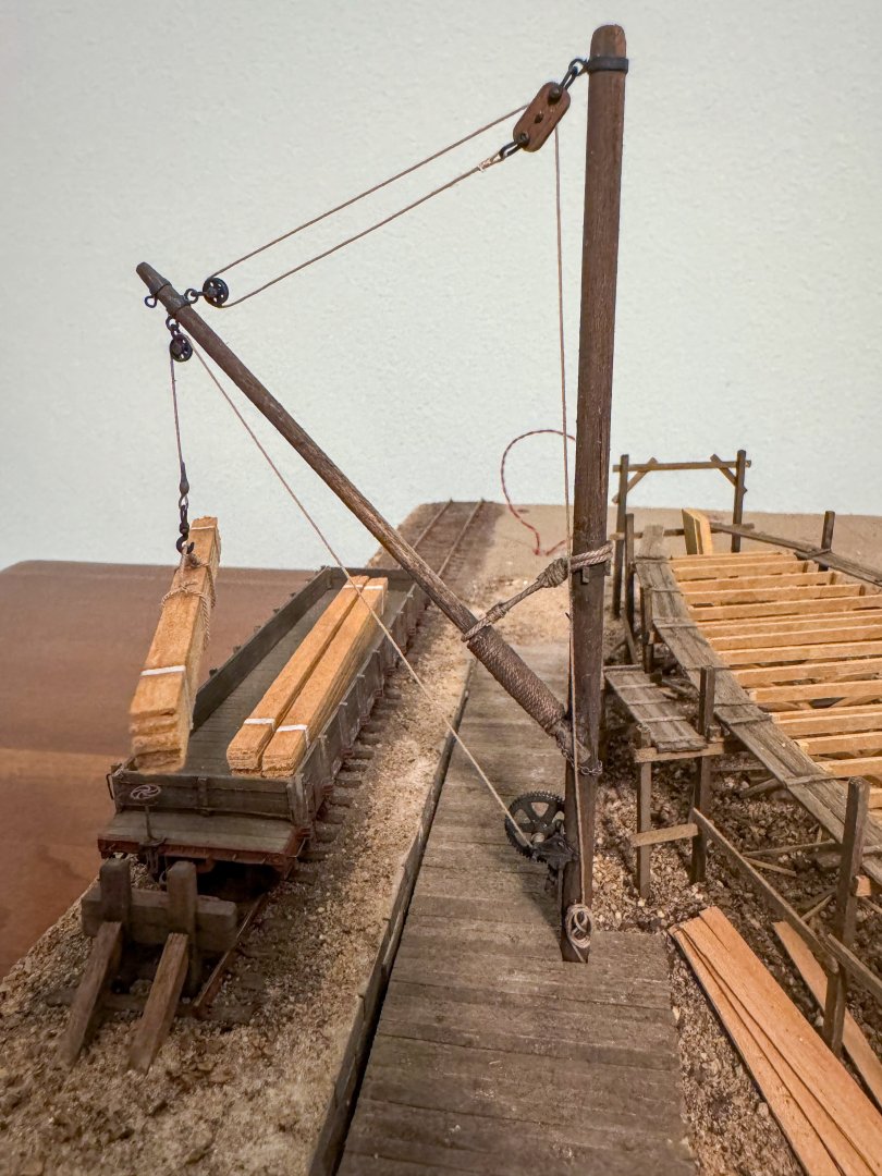
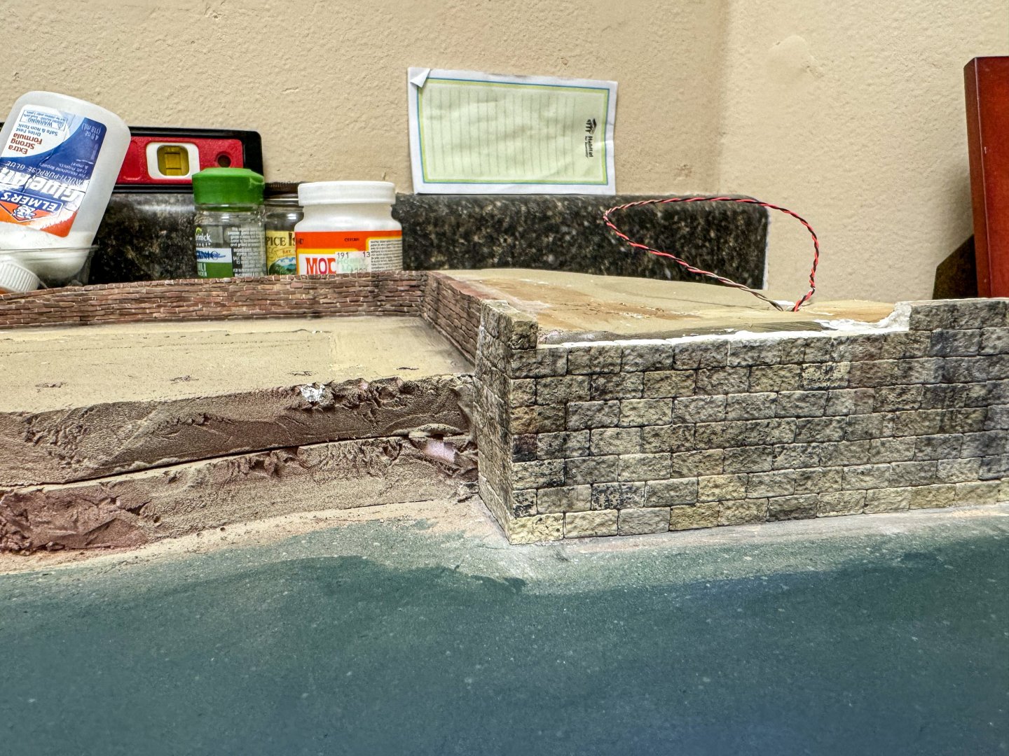
Meanwhile, back at the Shipyard... Prior to the sculptamold, I laid down the ballast for both tracks. The rails were already down on the left track, not so on the right. I don't really have an opinion as to which way is better although on the right, the ballast had to be glued then cleared from the ties before laying down the rails. Some color was then added to the ballast to tone down the rather bright grey. Some random oil stains were added as well. Here are some photos. Foss landing sculptamold was placed first. In preparation, the bumper pilings were made so that they could be placed before the mold hardened. I mixed the mold with some brownish paint and then placed the 2 landings in the soft mold, puling the wires through small holes in the decks. A mix of ground cover to simulate a slightly rock shoreline was then added. Tires were added to the pilings and here is the result. Next up was the mold for the Shipyard pit and beneath the dock. I ended up doing this in 2 stages as there is just too much going on with the ship and the surrounding supports and decks to try to get it all done at one time. Before mixing the mold, all of the details that have to be stuck in the mold were completed - scaffolding, supports for the ship base etc. The mold was then placed and the ship base placed onto to it. all the supports were placed, using the work decks to check placement. Additional ground cover was placed as well as discarded wood. The ground cover was glued and then it was all left to dry. The main dock was placed but not secured to ensure correct alignment of the ship. The dock at the left side of the pit was also placed at this time. Remember to push a rod through the dock into the mold for the derrick mast. Here is a shot of the wall at the end of the rail on the left showing a bit of collapse where there were no reinforcing stones. The mold beneath the dock was then placed followed by the dock. Pilings were then placed as were the tires. On another forum where I am posting this build, a suggestion was made to add a bull rail to the shipyard deck to keep stuff from rolling off the dock. seemed like a good idea so after doing some research on what this would look like it was added. Next, I constructed a bumper stop for the left rail based on some internet photos I found. Here's how things look now. The 2 docks on the side shipyard building have been glued. Here is a shot of where things stand so far. And finally, the derrick was constructed. from what I could find on the internet, the shipyard derrick is a "guy" derrick. With this type of derrick, the load is moved by either rotating the mast (not likely with this construction) or the boom. With boom rotation, there is an additional lashing between the boom and the mast for support. Derrick construction was straightforward. I decided to add a few bundles of wood to the flatcar and one being lifted by the boom. At this time the mast has not been fixed in place. The one support rope leading from the ring at the mast top will be added later. Jeff


- 87 replies
-
- 12
-
-
-
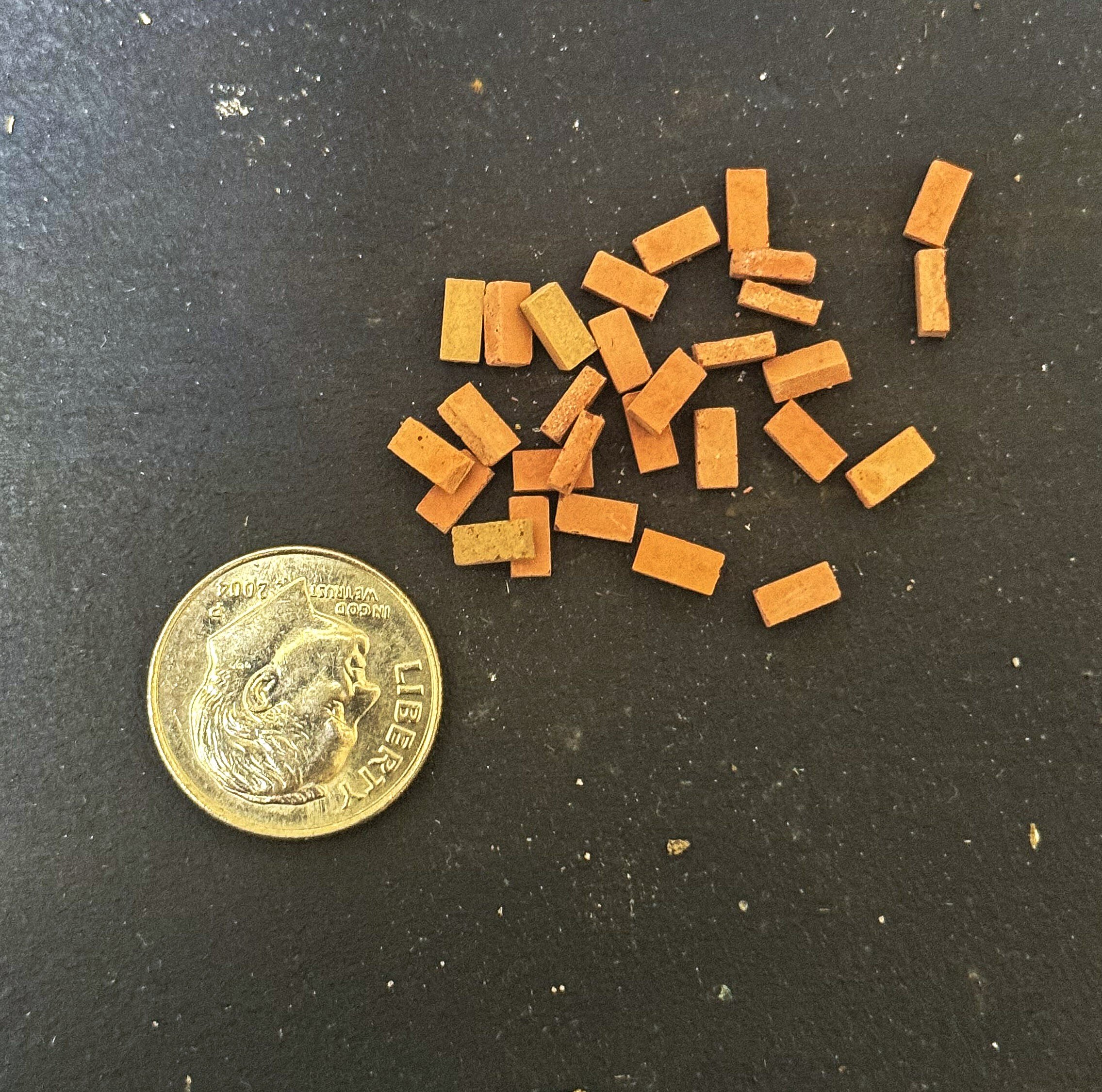
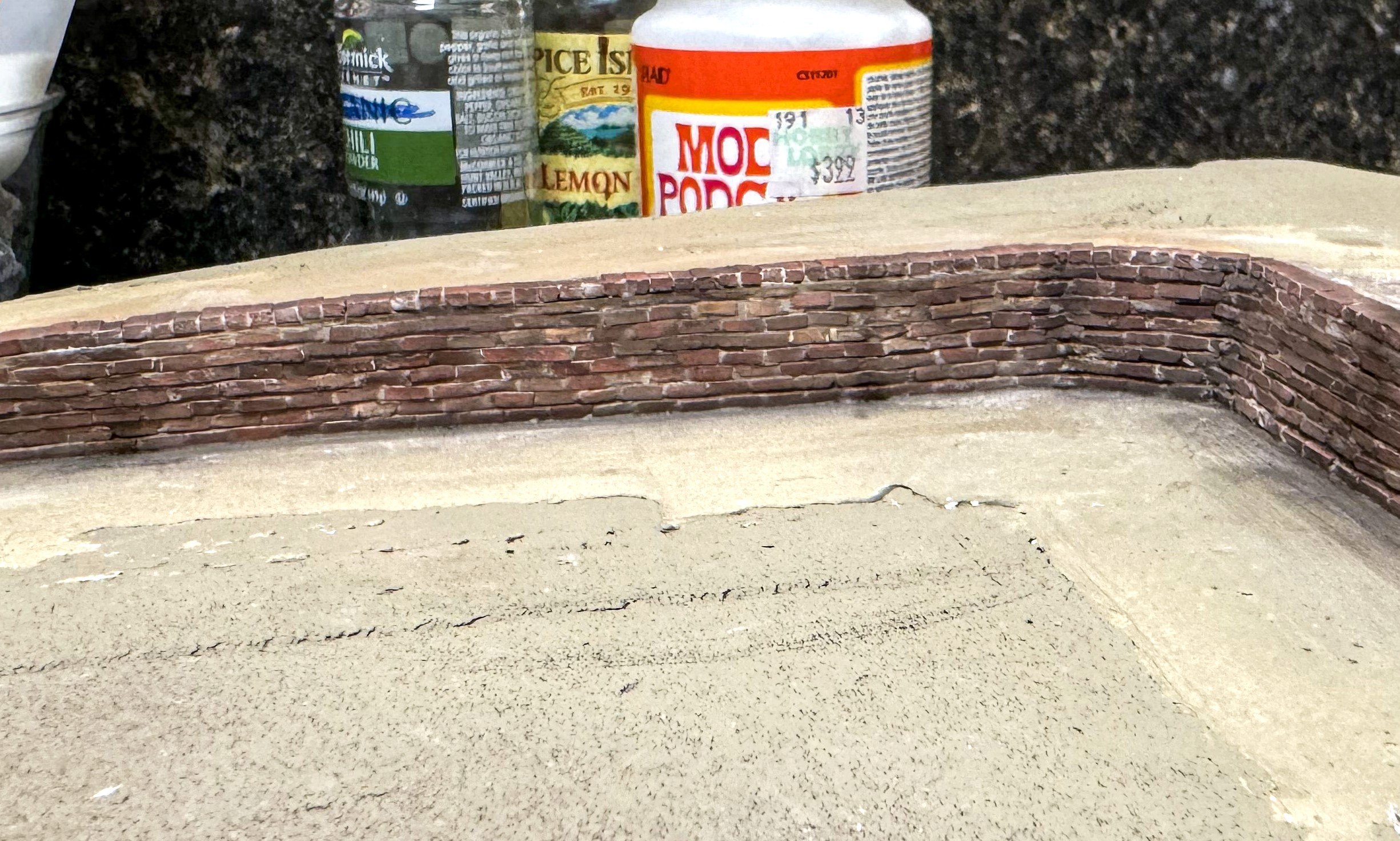
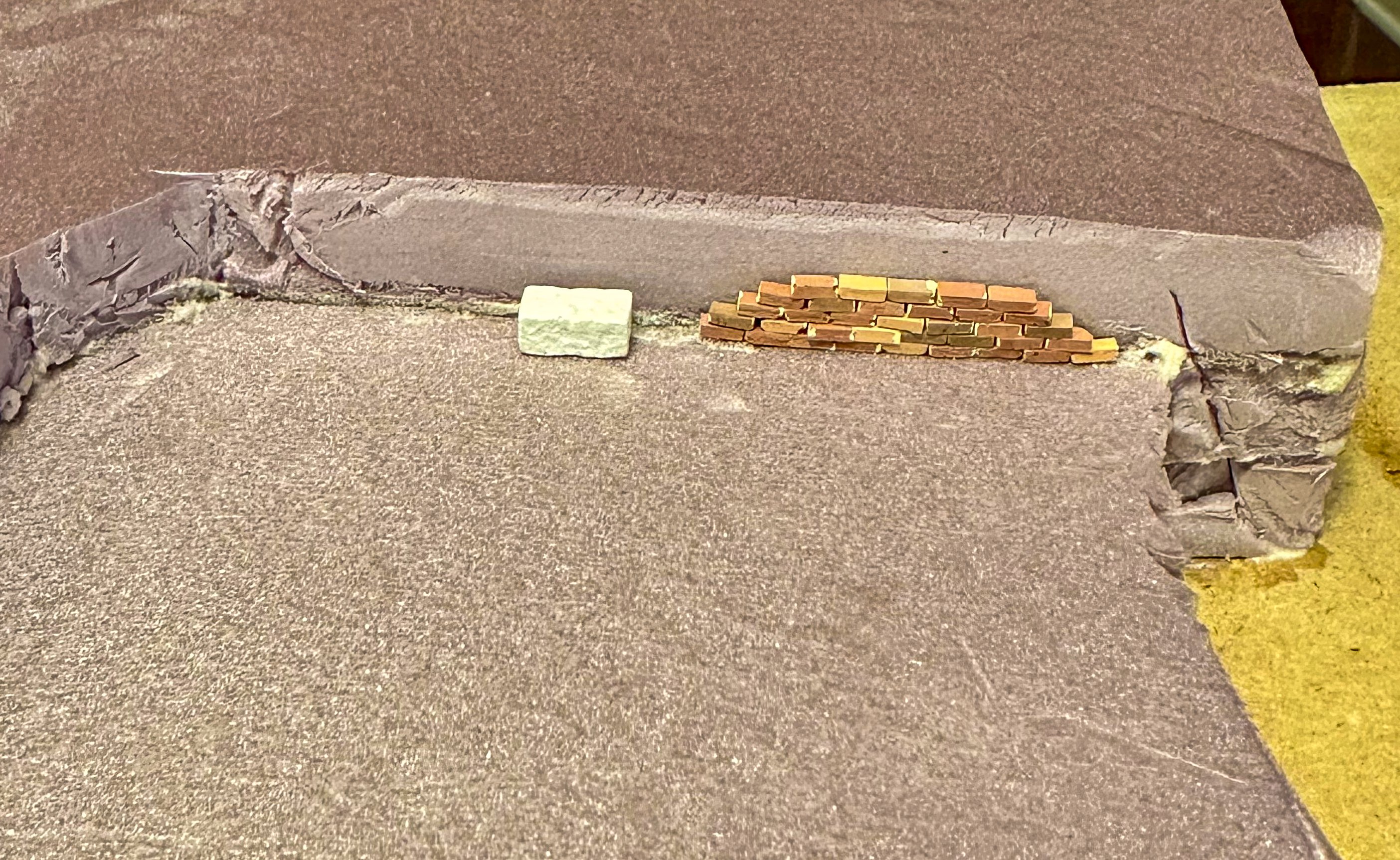
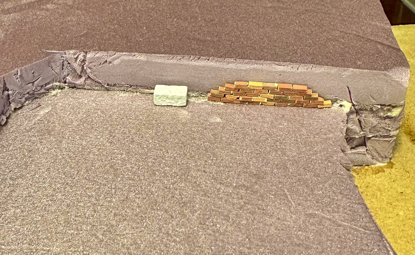
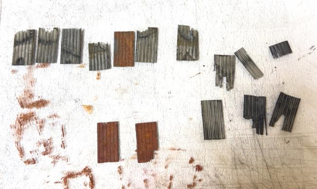
thanks for the comments. OC - the bricks I purchased on etsy. Just search for ho scale bricks and you will find them. I they were laid like full sized bricks, one at a time. White glue on the bottom and a small amount of joint compound on the side to simulate mortar. In between rows I used a thin strip cut from a 3x5 card for separation and some more joint compound when the wall was complete. Here is a sample of some loose bricks. Jeff

-
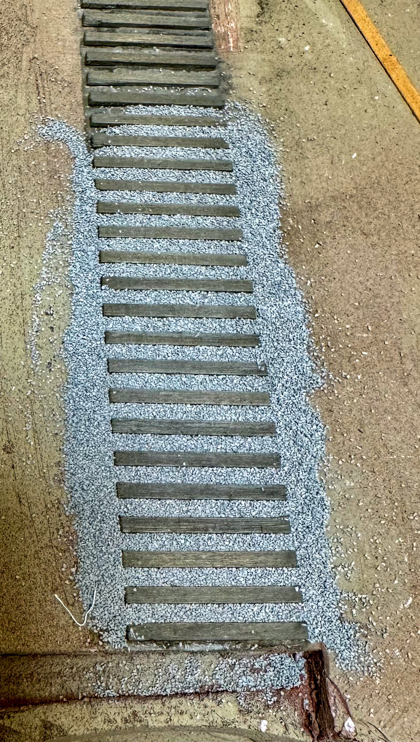
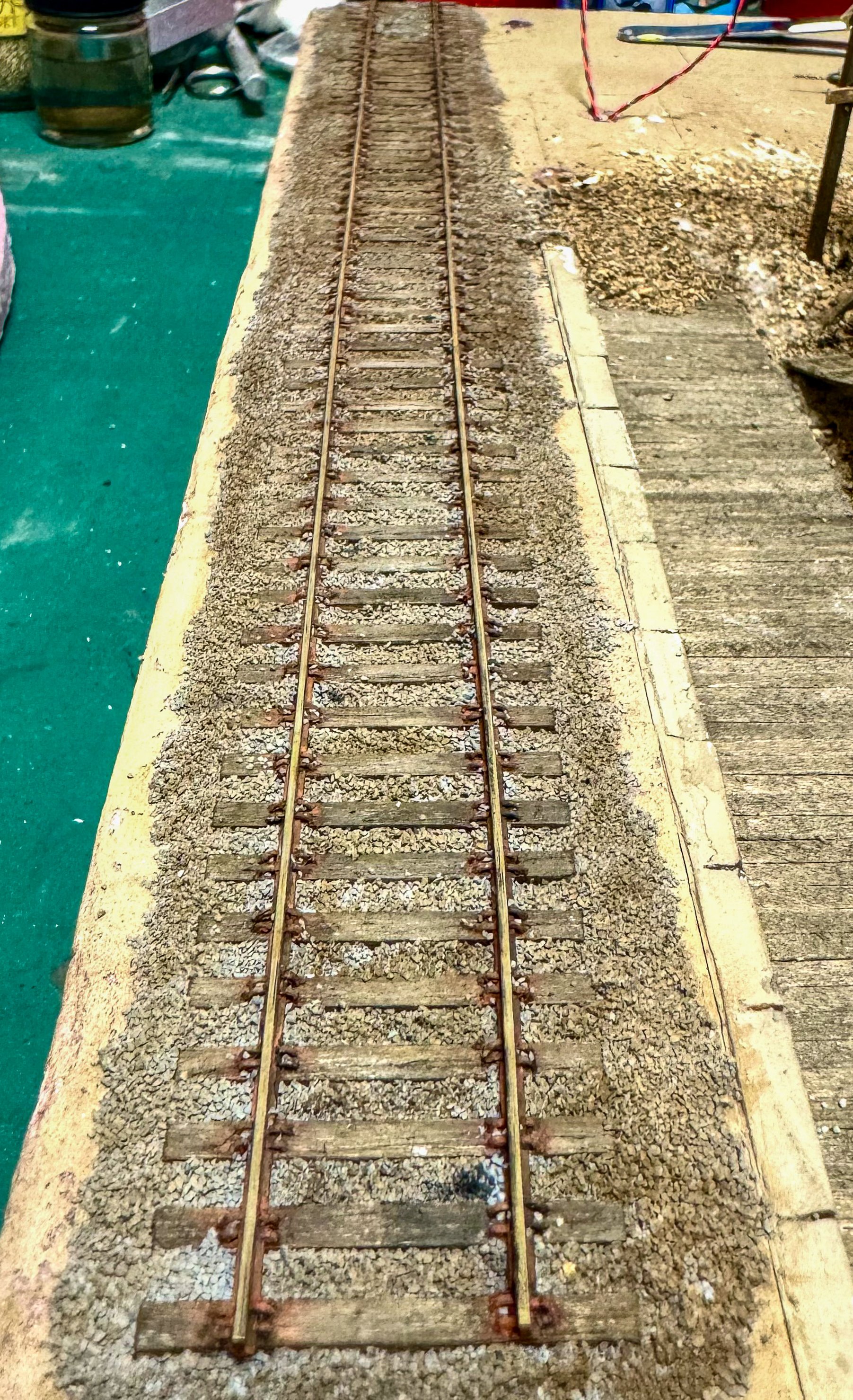
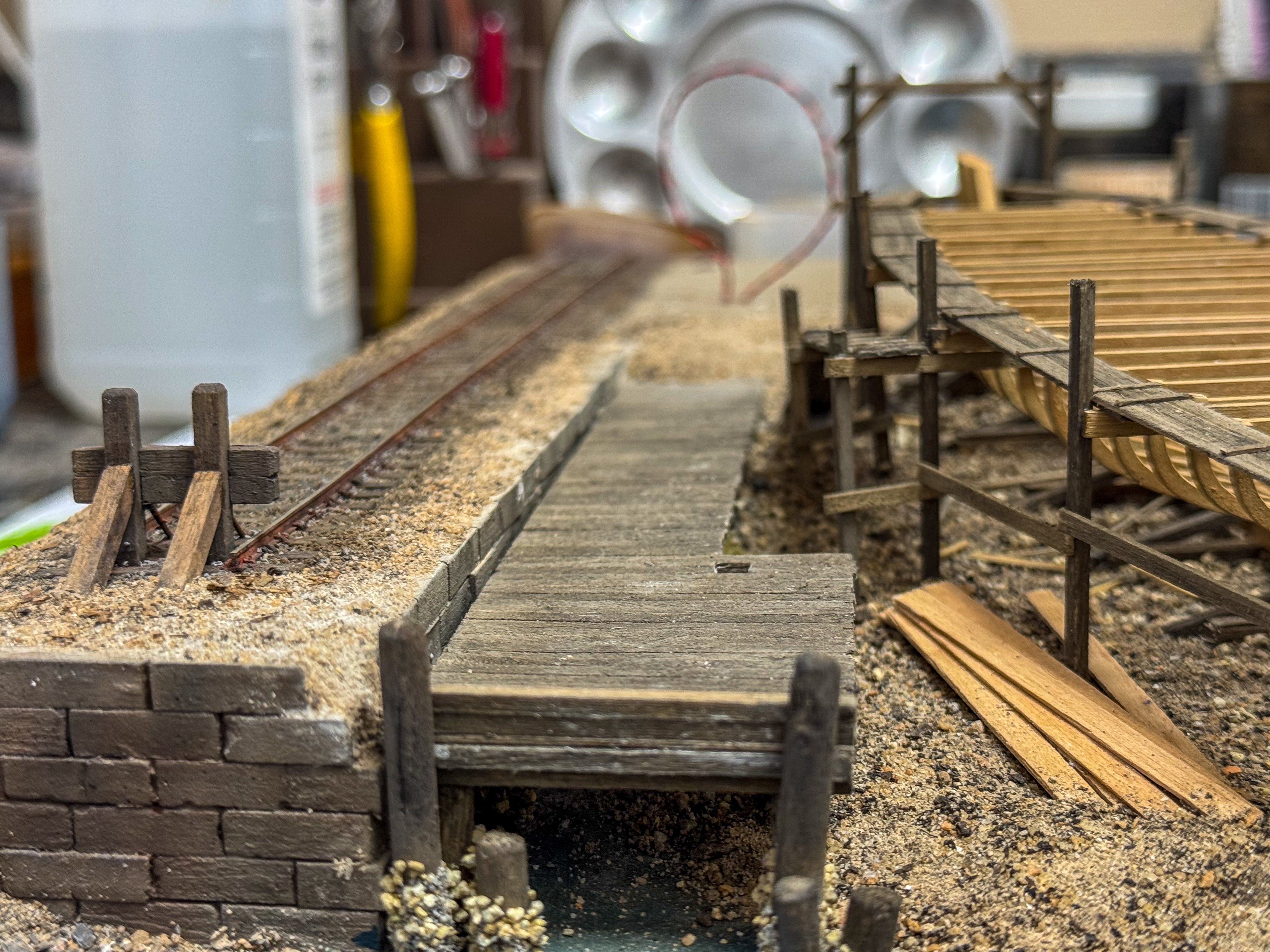
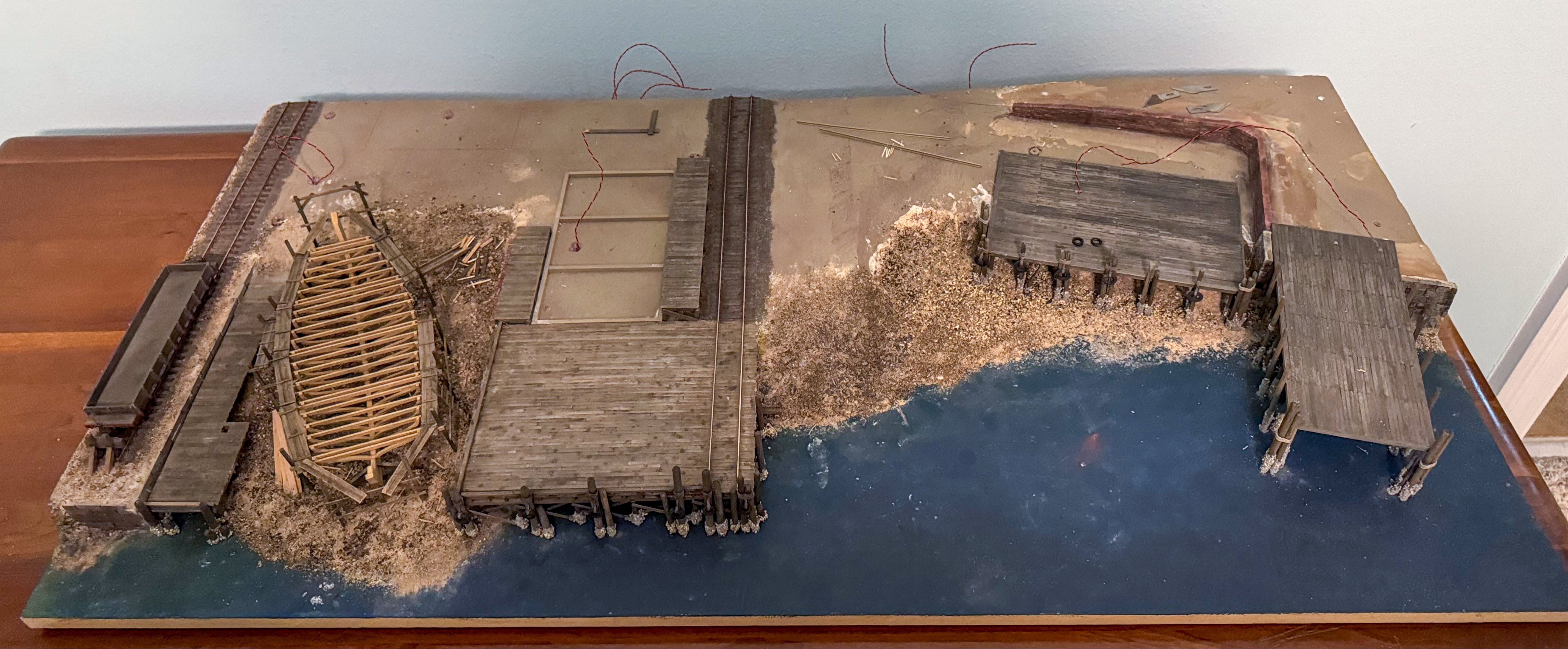
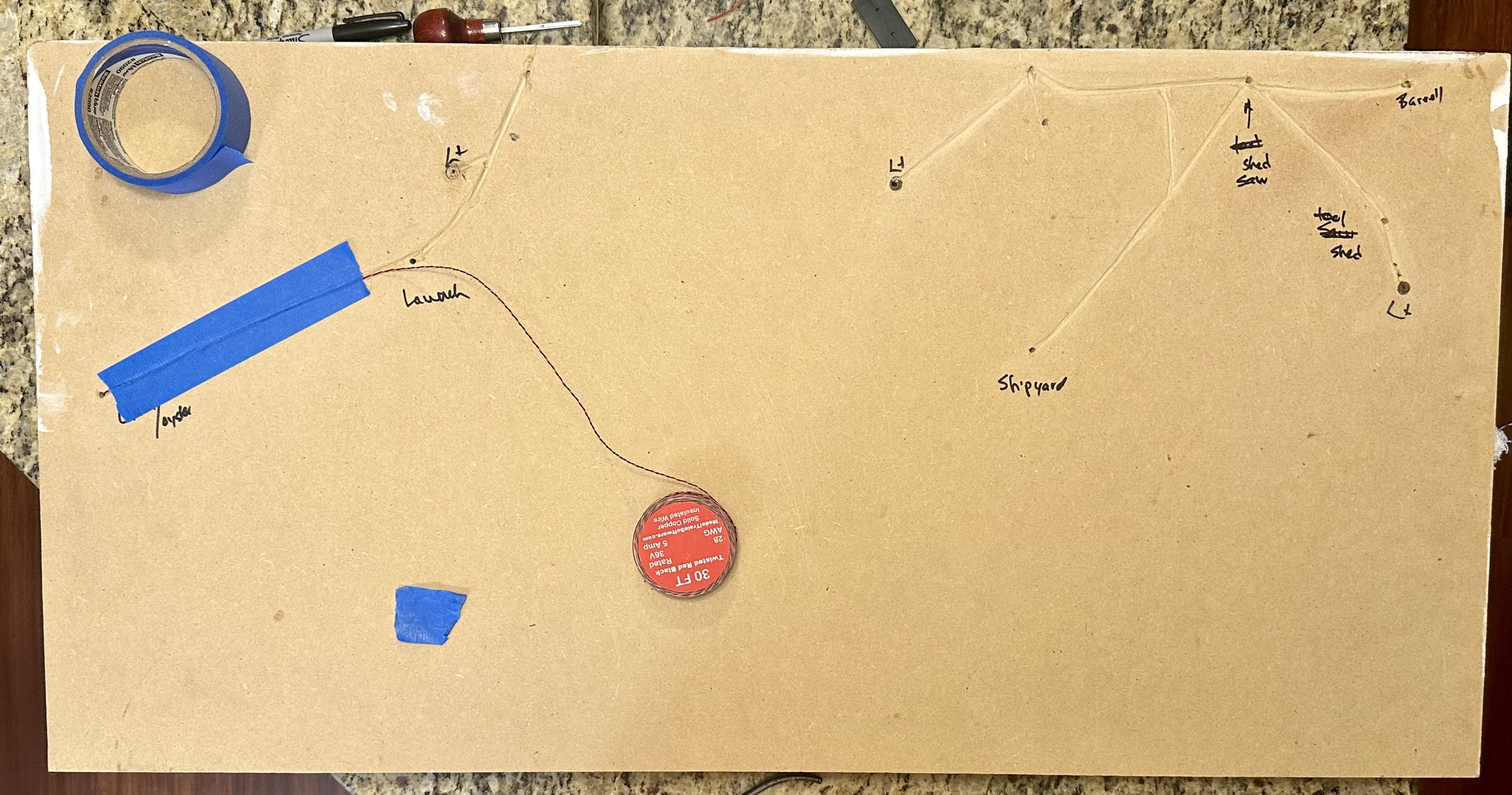
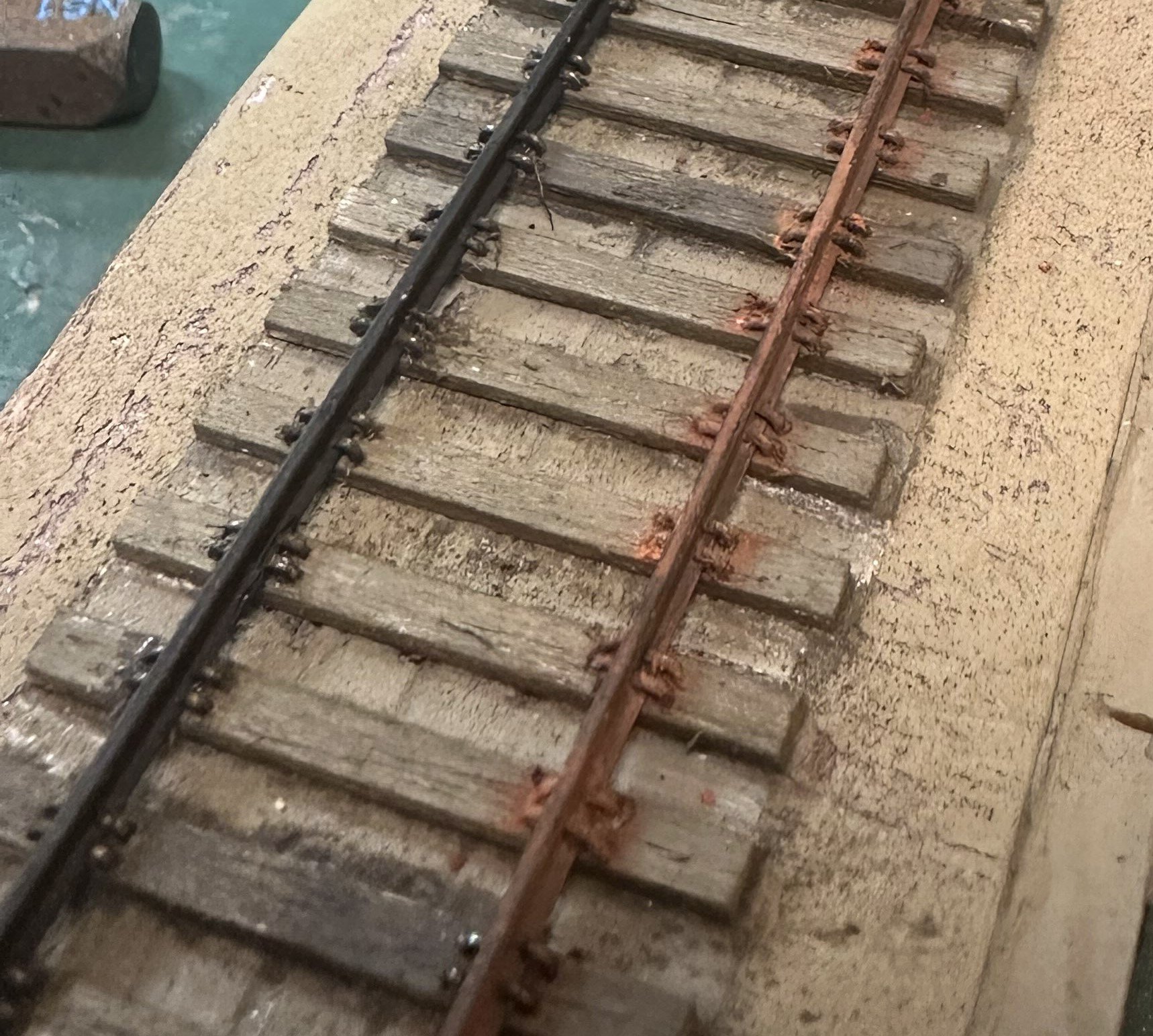
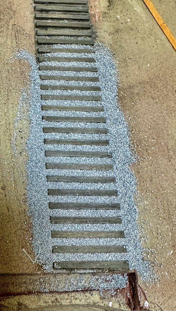
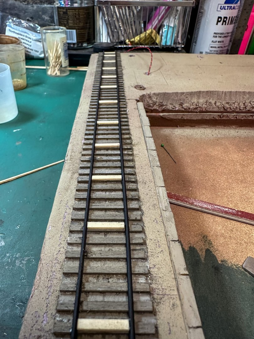
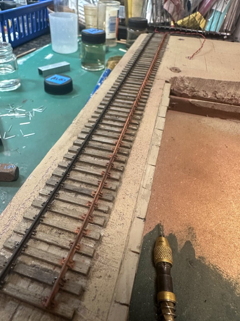
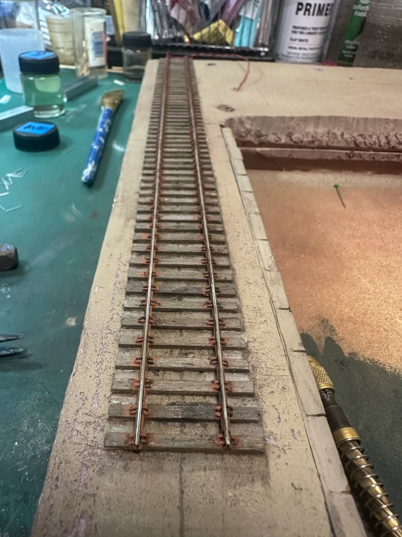
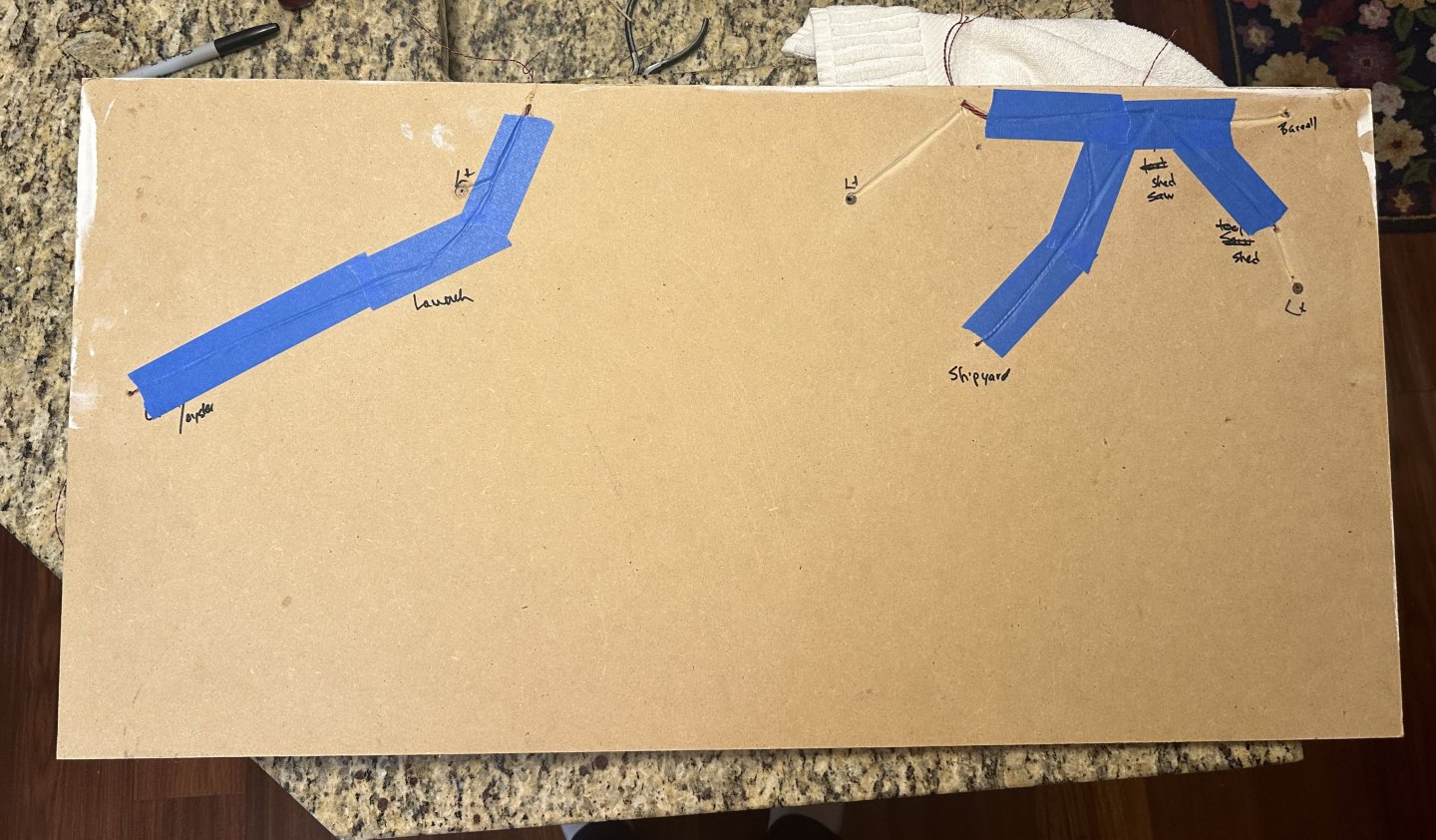
Greetings! Work continues with the shipyard. After all the RR ties are placed, the base was painted where the water will eventually go. There are wires poking through the MDF and insulation base. These will be spliced to the various buildings and light poles. Here are 2 photos of the underside of the base. MDF is perfect for gouging out small trenches for the wires which will then come out the back and eventually get spliced into 2 on/off switches. Each hole is marked to identify the structure associated with the wire. Next up was the brick wall that replaces the concrete one on Foss Landing. The wall below the Clam and Oyster building was made up of larger blocks, much like the wall near the RR tracks on the Shipyard kit. The RR track was next glued to the ties after they were weathered. The flex track I purchased came with plastic ties so, before the plastic ties were removed, the track was centered and marked on the weathered ties. One rail was glued first then spacers were used to keep the second track even with the first. When all was done it was tested with the RR car previously constructed - perfect fit. I wanted to add the rail spikes for extra security. However, what is commercially available looked out of scale. I ended up using standard paper staples - still a bit out of scale but closer, I think. He is a photo. It was a lot of drill holes and spikes! The rails were then weathered, and a sanding stick was run across the top. Next up is the sculptamold for the Foss Landing buildings, followed by the Shipyard pit. Jeff


- 87 replies
-
- 12
-
-
-
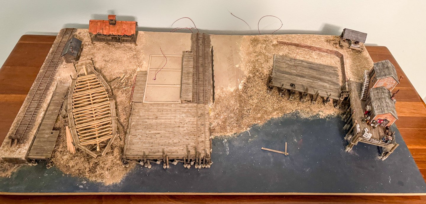
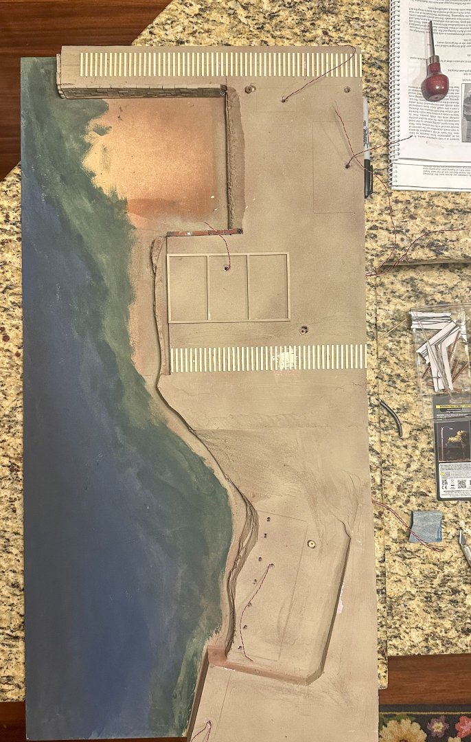
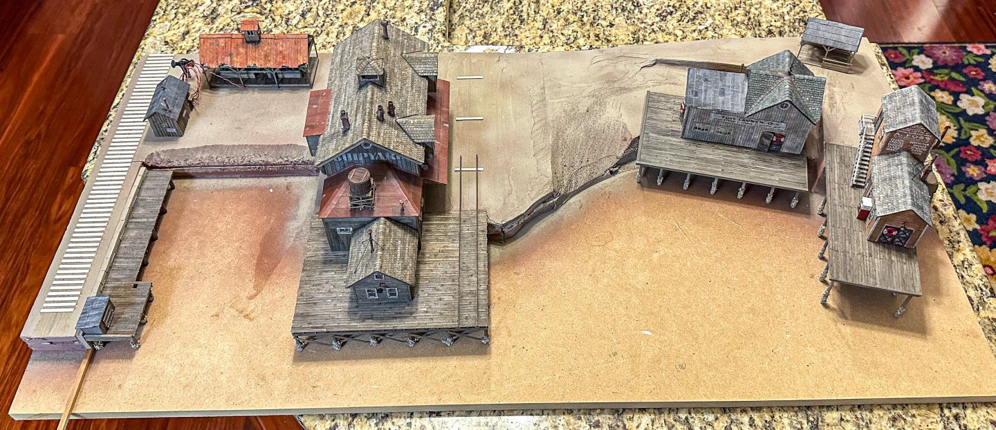
Greetings ! A few weeks have passed since my last post but progress continues. Now that all the structures are complete, it's time to work on the foundation. 1/2 inch foam board home insulation is used for the various levels, glued to the MDF base measuring ~ 36 in x 18 in). Some sheet-rock compound was used along the sides and the seams and to cover the upper level of the Foss landing side (right). Pilings and mussels were added to the 2 docks of Foss landing and the one for the Shipyard after the support boards were added to the pilings . After a coat of spray paint, the RR ties were laid down on the left. Rather than tape them to a template and glue them all at once (nicely demonstrated in Grant's Shipyard log), they were laid by hand using a long piece of wood for the boundary on the left and wood spacers to keep the distance between ties the same distance. Here is the work in progress: Before proceeding with the ties on the right of the shipyard, a bit of compound was used to build up the base so the ties would fit snugly under the rails. The "ship in progress" was also completed. As in Grant's log, the wood was left unstained to simulate newer, non weathered wood. Other things to think about is how to run the wiring from each structure through the base to the batteries. More on that later. Here are some photos of progress so far. I've been taking it slow as I have to go between the 2 instruction manuals so I don't get too far ahead on on side or the other. One modification of the Foss landing kit - a cement wall is called for that starts behind the launch Co building and goes to the side of that building and then forms a cement wall under the Clam and Oyster building below the dock. The Shipyard kit has 2 walls, one of brick and one with larger stones. To tie the 2 kits together, I've decided to replace the cement wall with bricks at the back and side of the launch co and larger stones for the wall under the Oyster Co dock. Here's a sample of the bricks and one stone: Jeff


- 87 replies
-
- 13
-
-
-
Fixed it = "metal roof". The material supplied was aluminum. jeff
-
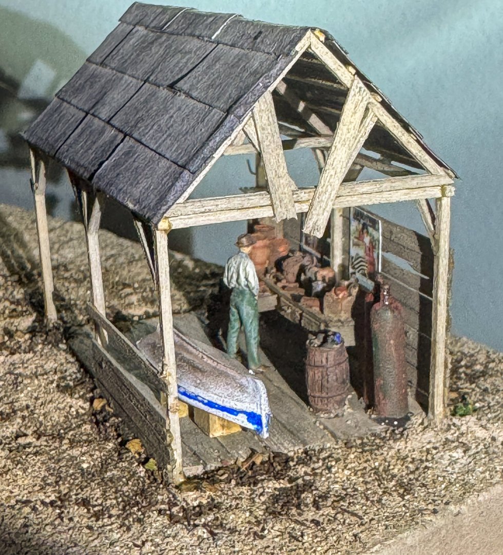
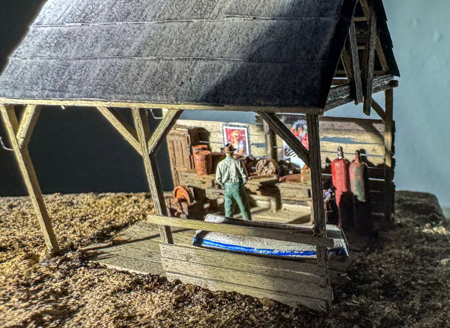
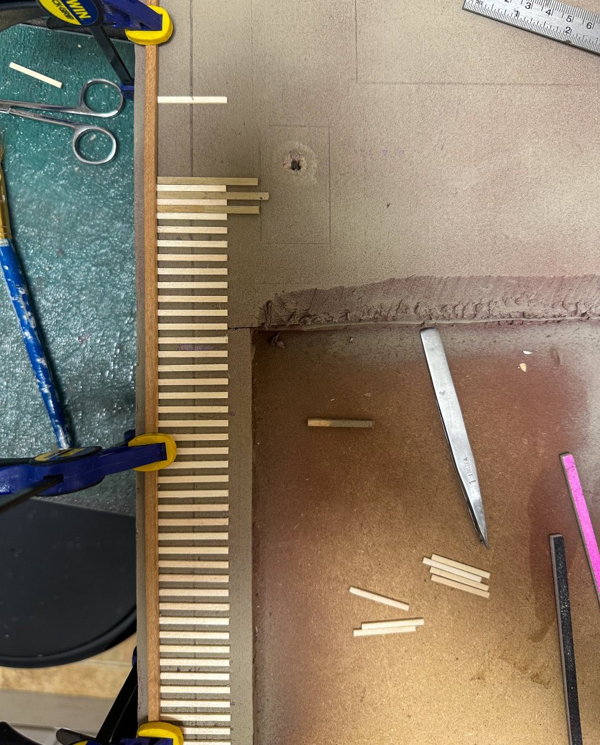
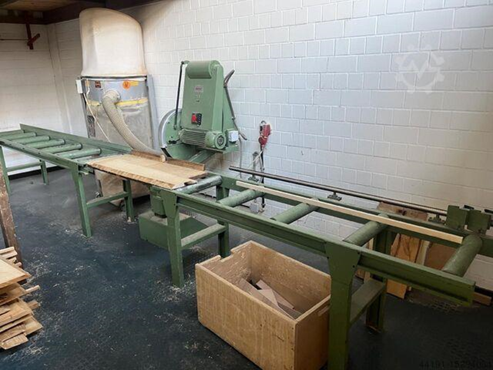
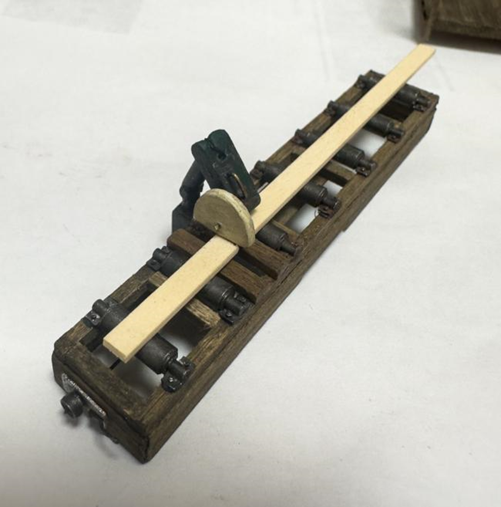
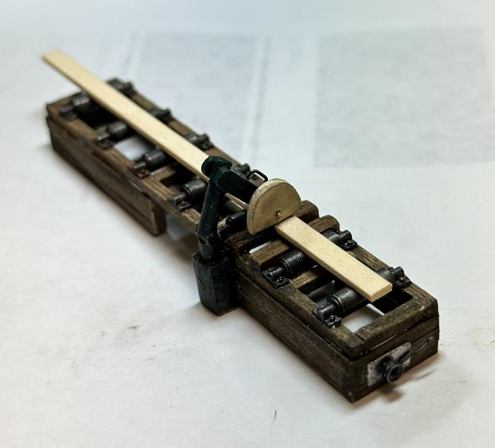
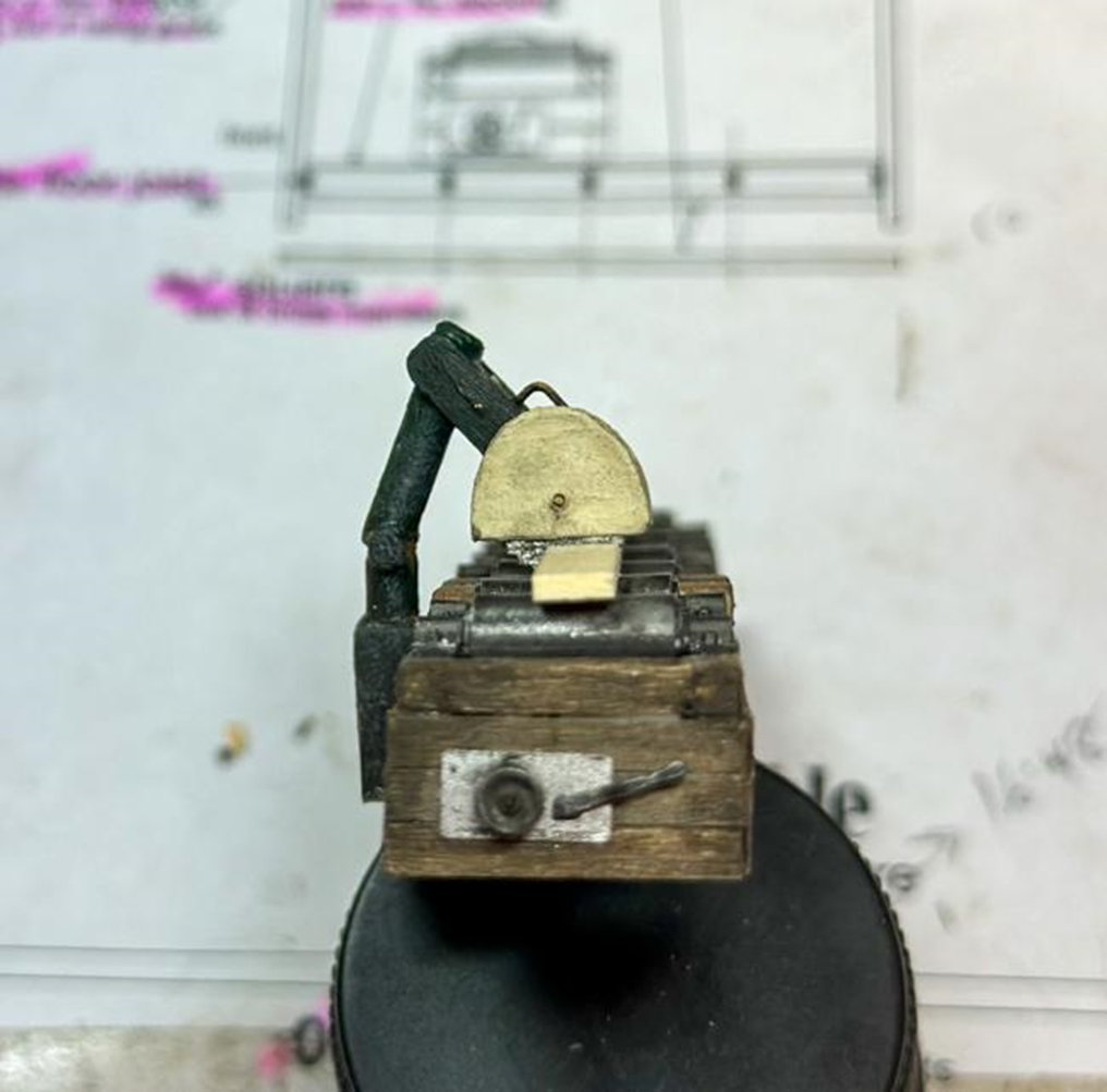
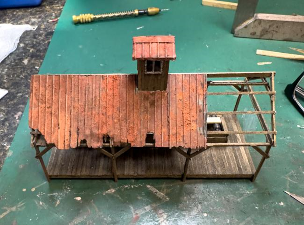
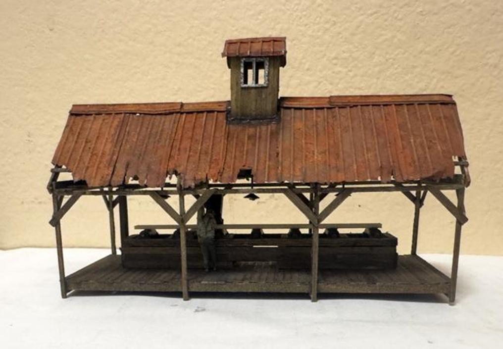
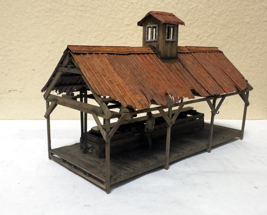
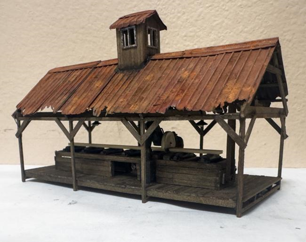
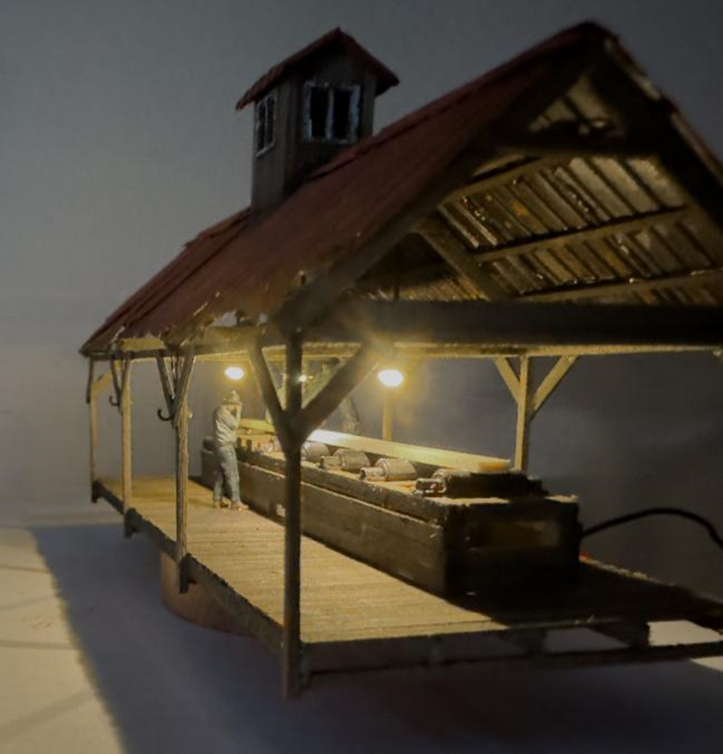
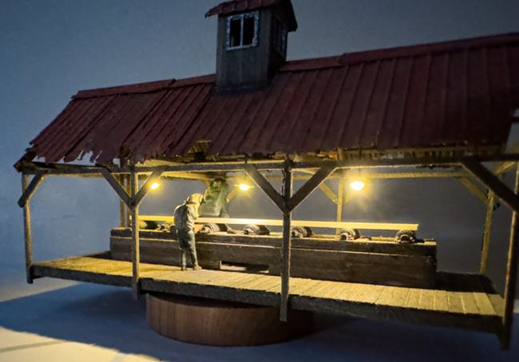
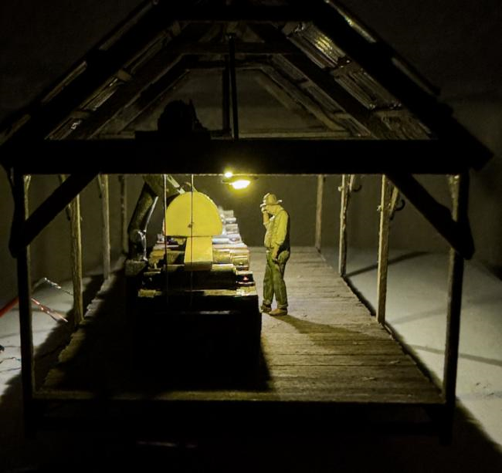
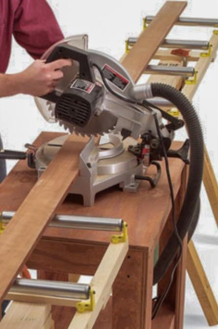
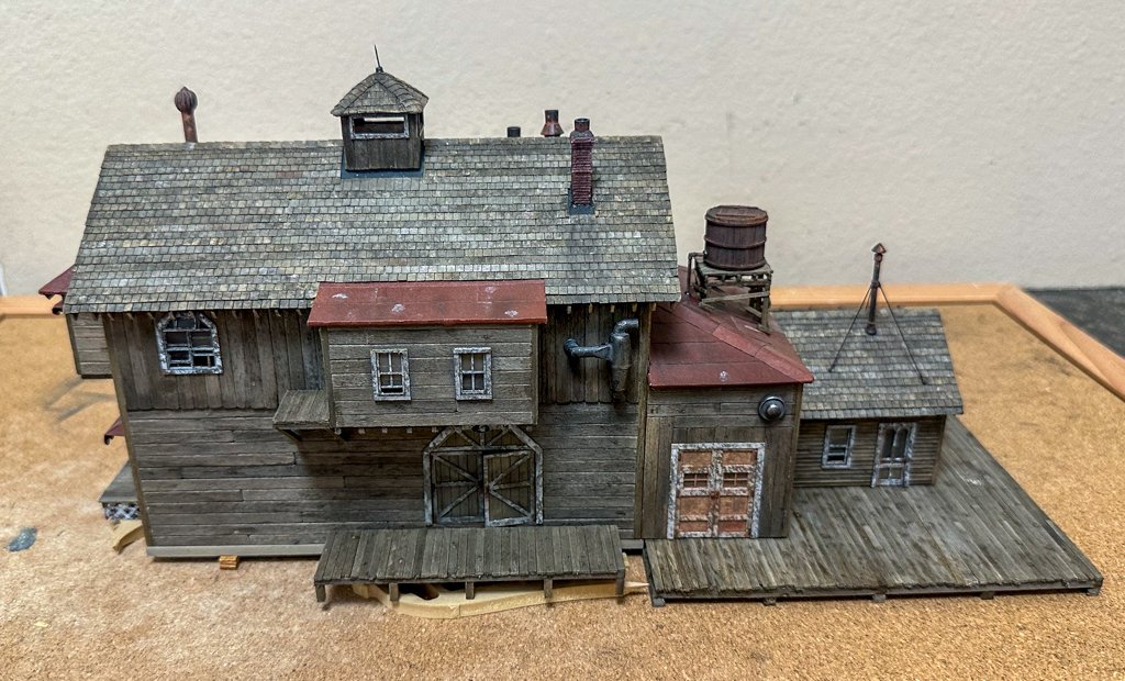
Greetings: Having finally decided how I want to deal with the saw, here's what I came up with. A pendulum saw would be appropriate for the type of roller table featured in the saw shed. Here is an example: With this in mind, it was time to go to the scrap box to see what I could come up with: The wood plank sits nicely on the rollers with just a bare minimum of clearance of the 2 wooden beams on either side of the saw. The saw machine is double hinged allowing it to be pulled across the table to saw the plank. The remaining features of the saw shed (upper level, motor, drive shaft and belt) were next completed. These are all very well described in Grant's log so I won't repeat. There was no variation from the instructions. The final steps were construction of the cupola and the rusted metal roof. Here's a photo of some of the roof pieces after etching and some rust chalk applied. Roofing in progress with cupola installed: Prior to placing the roof supports and roof, I added 3 LED hanging lights. The wires are so small i just glued them to the overhead supports and vertical beams so the wires end up under the floor. These can be seen in some of the photos below of the completed saw shed. And here are some photos with the lights on (with a worker wiping his brow): Next up is the base which will begin the process of combining Foss landing and the Shipyard at Foss Landing. jeff
- 87 replies
-
- 13
-
-
-
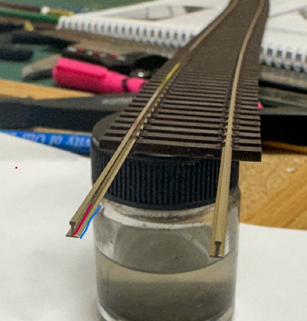
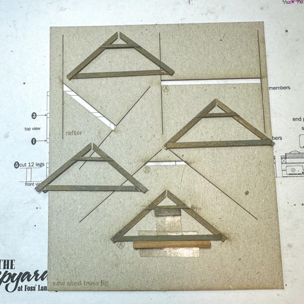
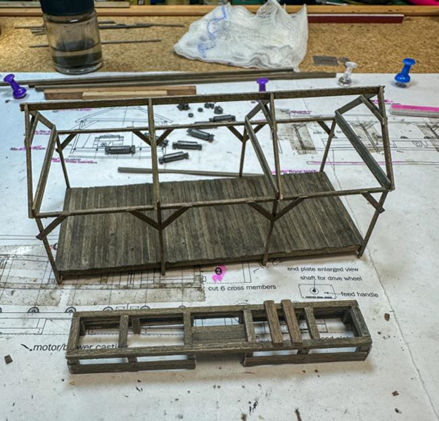
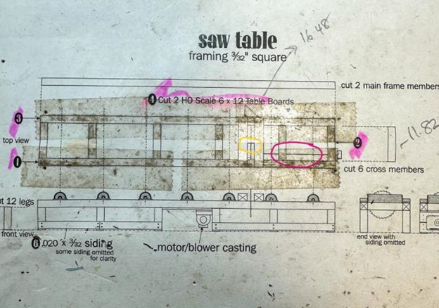
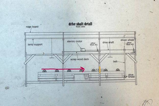
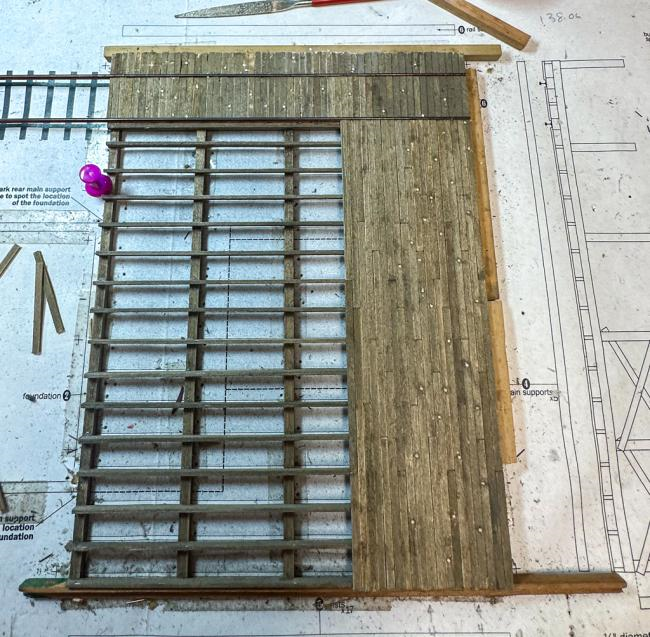
Greetings! Work continues on the saw shed. The floor was next. Instructions were a bit contradictory as the floor boards are to be the same length as the crossbeams however you are instructed to cut a notch in the boards to accommodate the vertical beams. This notch would not be needed if the boards are as long as the crossbeam so I did not do this. The 4 trusses were easy to construct using the template. The trusses were then glued to the upper crossbeams. That takes us to constructions of the saw table. Construction was straightforward using the supplied plans as a template. Some logs show 3 boards used to cover the table sides however I just used 2, similar to what is shown on the plans. 3 were used on the side where the end plate will be placed. Next up is the hardware. I have several questions I hope someone on the forum can answer. 1. There is motor that sits on a platform above the table that has a drive shaft that is connected to a pulley and belt. The belt connects with the drive shaft wheel on the end-plate of the saw table. Connected to this pulley there is another drive shaft (pink circle in photo below). What would this shaft be connected to? The exact layout is not described in the instructions as it is hidden under the table so no need to build it. However this leads to the problem of how exactly does the saw / roller system work (see Q2 below). I am assuming the motor runs the saw, but maybe not? If it is the saw, wouldn't it be more appropriate to line up the end-plate with the center hole of the saw (yellow circle)? I guess it could be offset with another set of pulleys and a belt to drive the saw. 2. Given the layout of the saw table rollers, I assume the path of the wood along the table would be the pink arrow in the photo below. The yellow line represent the saw blade. If this were the case, would there not be a mechanism to move the blade up and down to accommodate movement of the wood? Either the blade would have to move downward to allow the wood to roll past and cut the wood as it is moving back up, or the blade move up and cuts when moved down like the illustration below. My assumptions at this point are the drive shaft runs the blade and there is another set of pulleys and a belt under the table. As such, the blade would have to move downward to allow for the planks to roll past and be crosscut. It seems to be an unusual set up and when looking at other build logs of this kit, I've always wondered how this set up would work I am probably over thinking this but I would like to hear some opinions before i start to glue the gear on. If you want to see a detailed description of how the motor and drive shafts are set up, refer to the log by gdale thanks Jeff
-
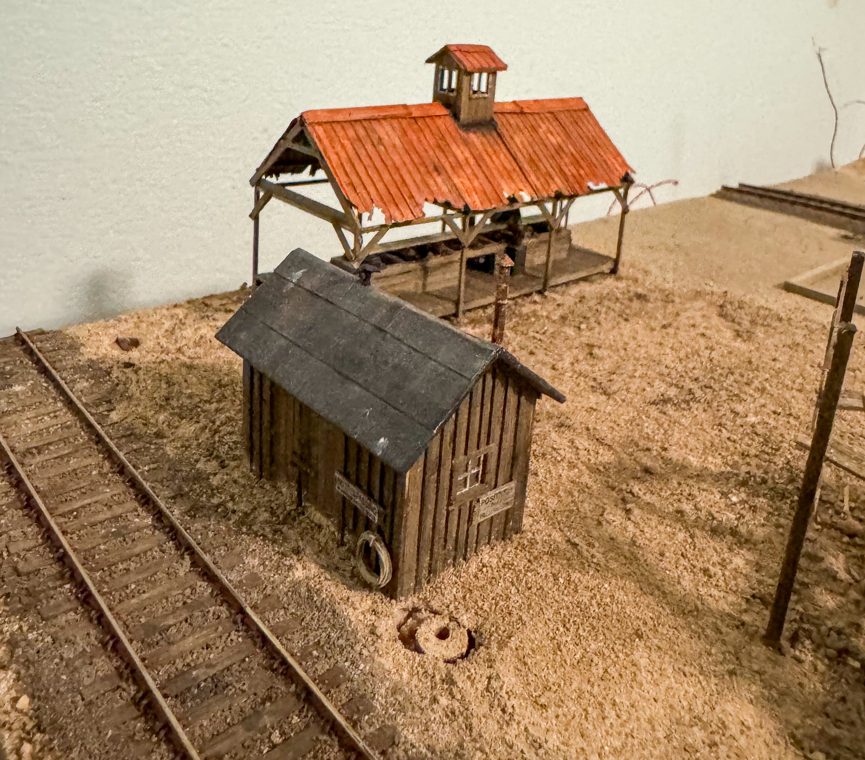
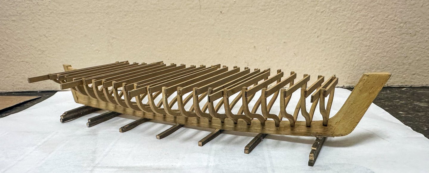
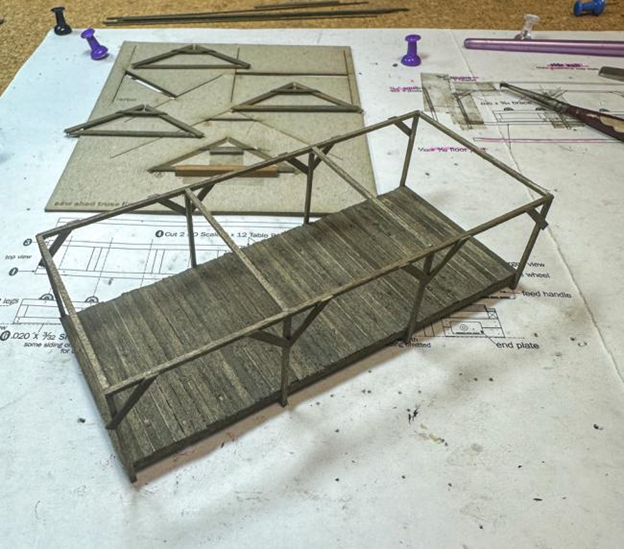
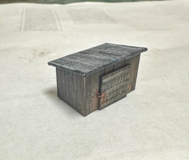
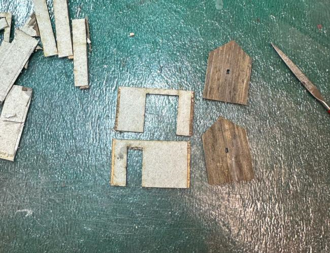
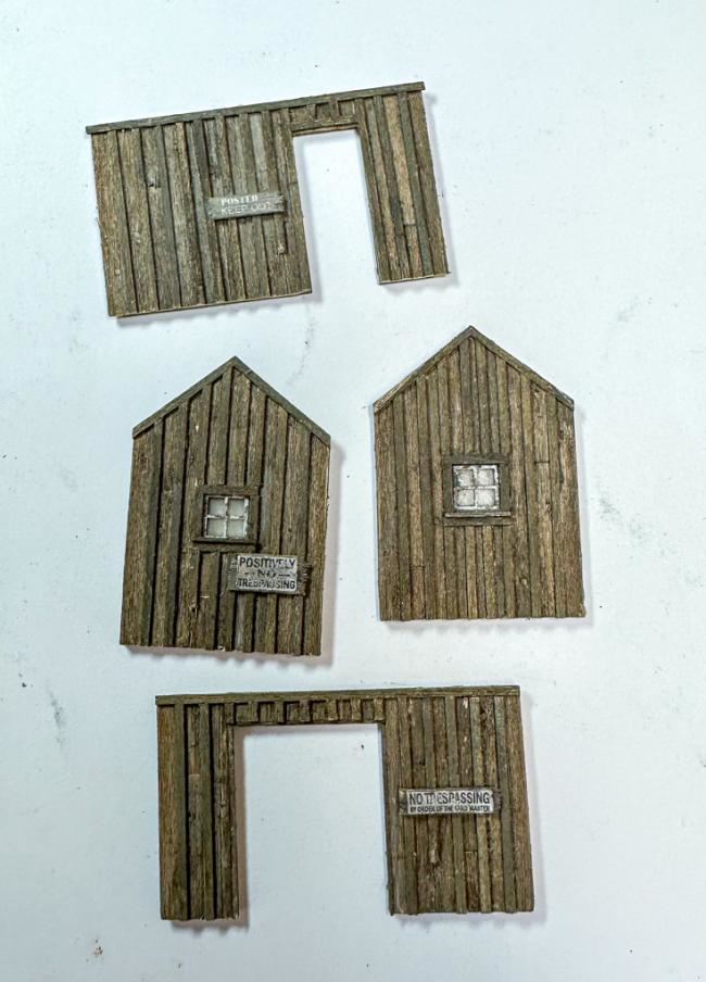
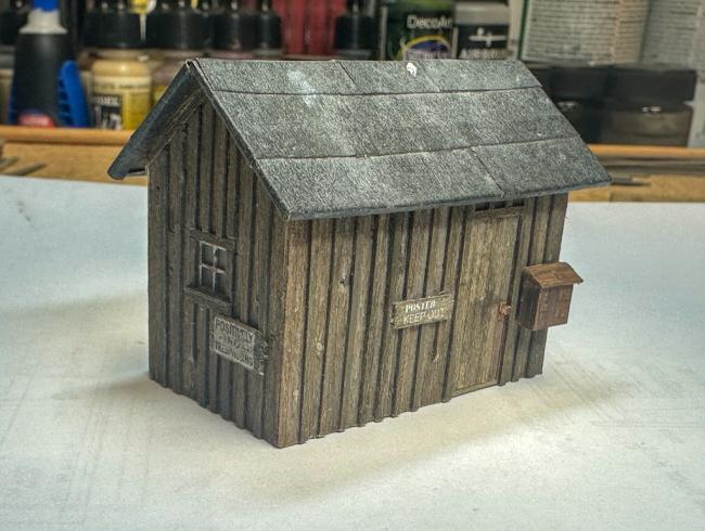
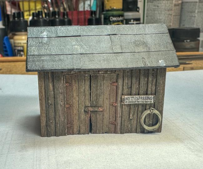
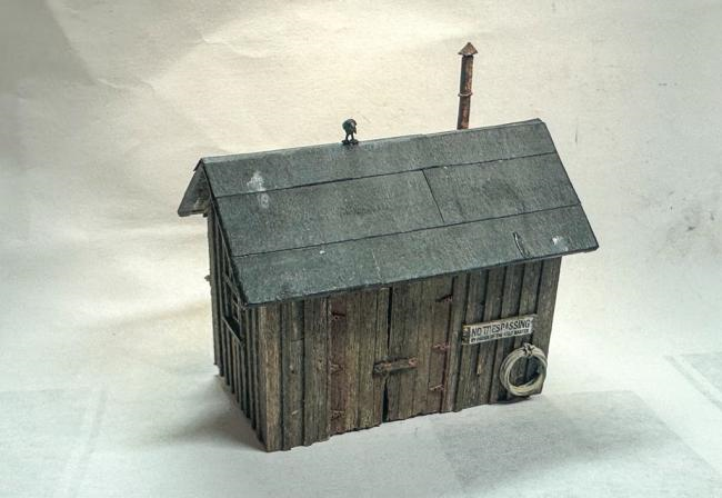
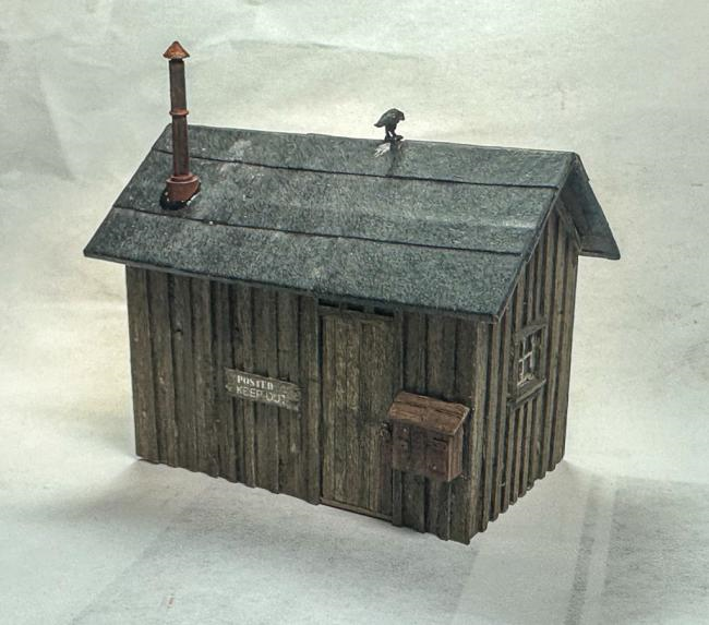
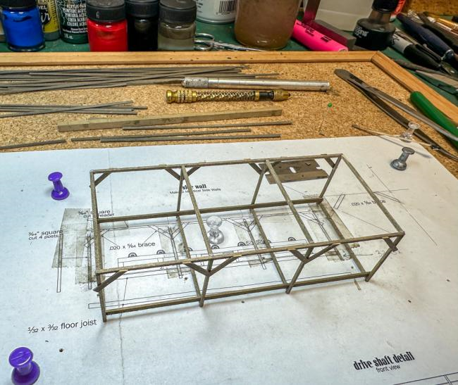
Greetings! The derrick dock shed and the upper yard storage shed have been completed. Not much to add as the instructions and construction are both very straightforward. Here's the derrick dock shed... ...and the upper yard shed below (the first photo shows the "strip wood trap" where just a mm or 2 of the first plank is glued to the underlying template, thus creating a space where the side walls will be glued. The joint between the walls is barely visible in the photos below.)... note the crow resting on the roof. Onto the saw shed. The frame has been completed. It is quite delicate at this stage. Jeff
- 87 replies
-
- 12
-
-
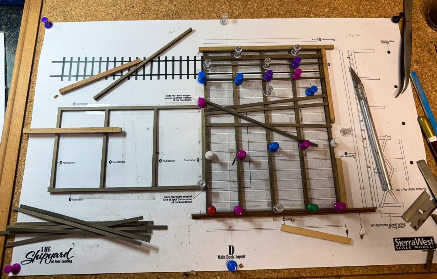
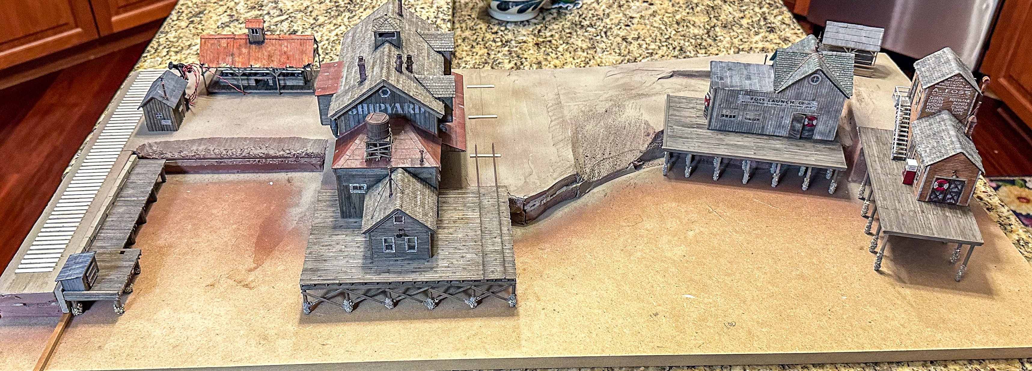
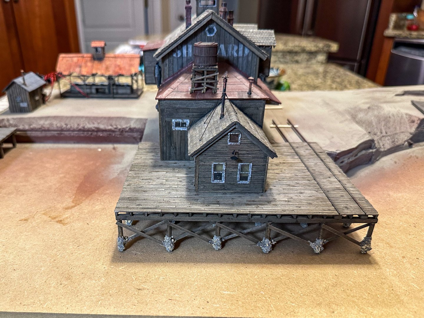
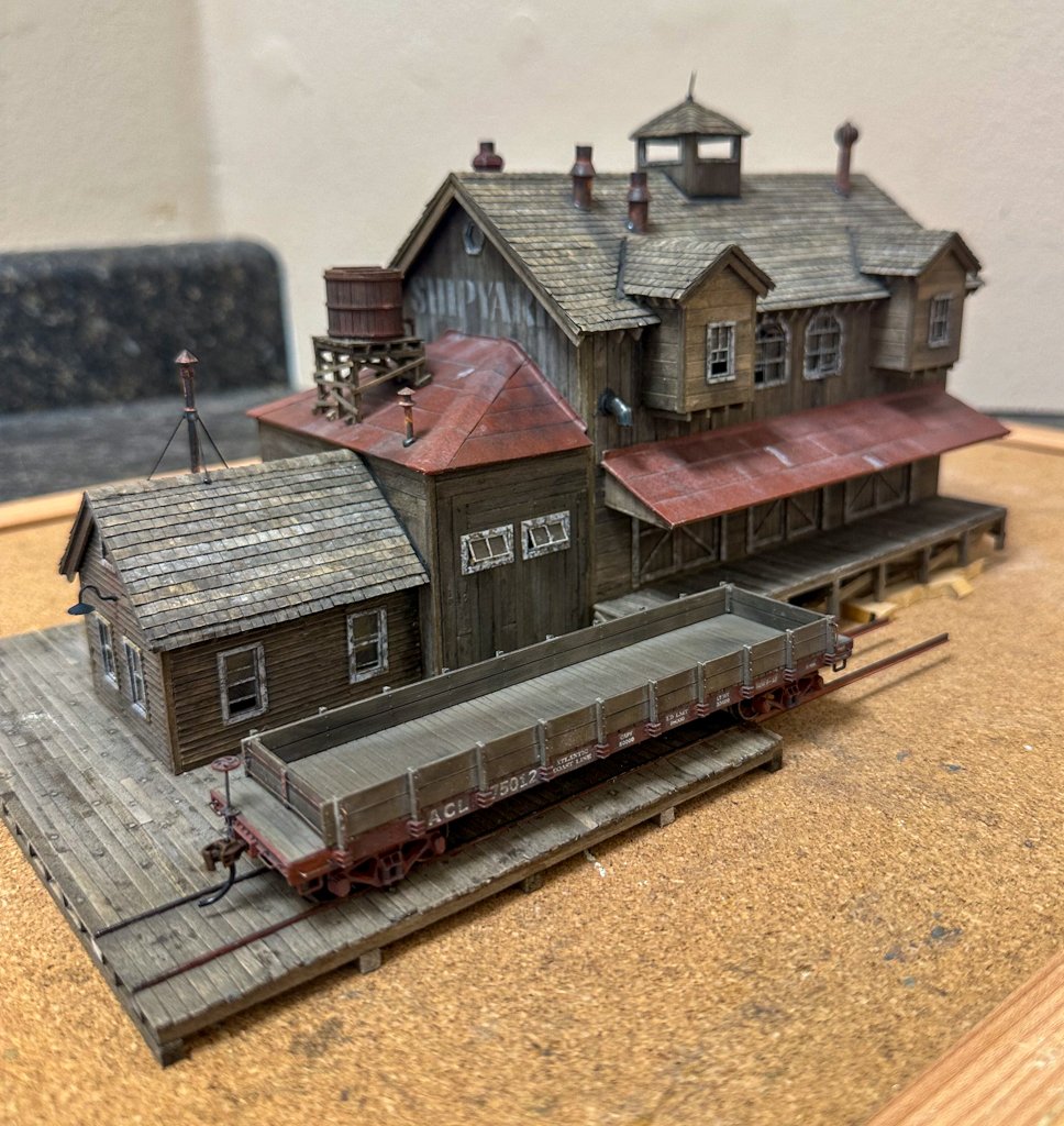
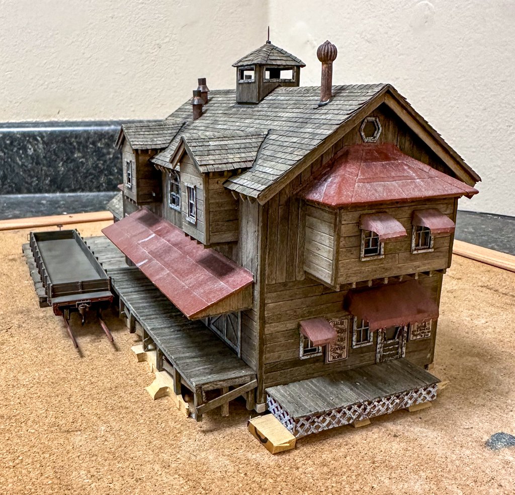
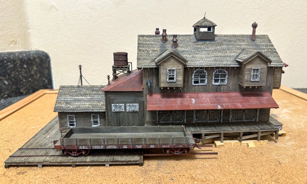
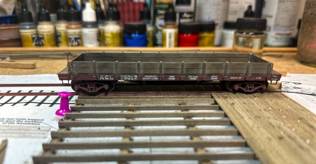
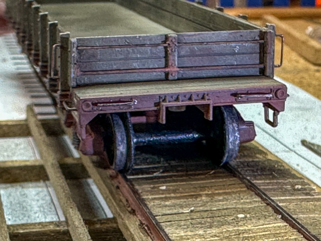
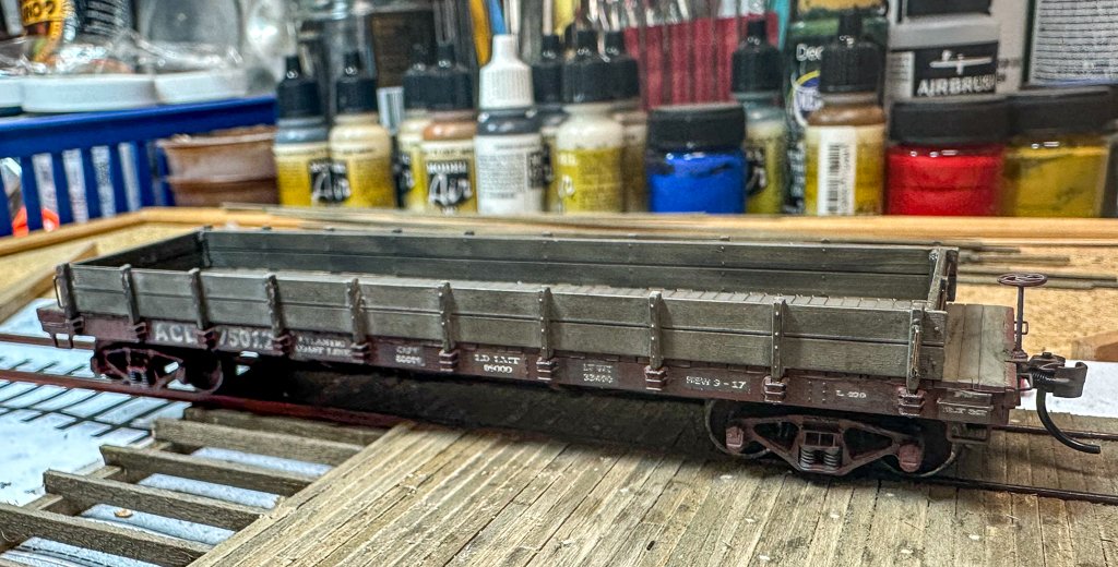
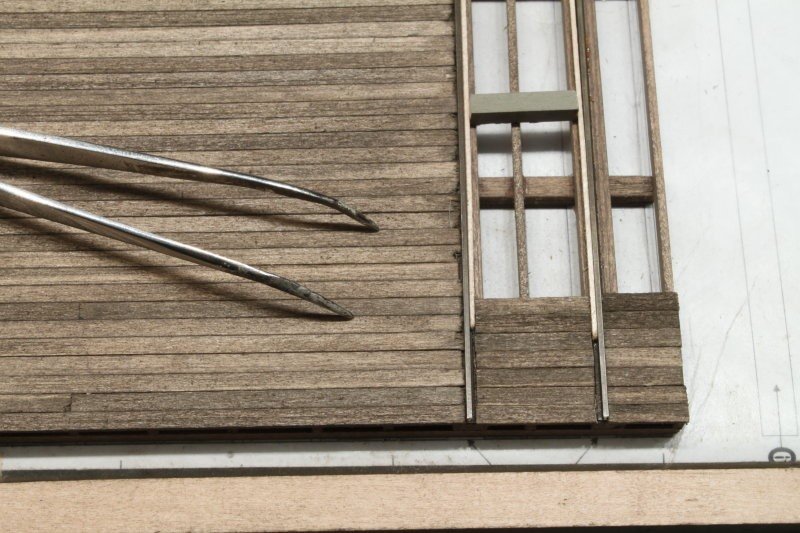
Greetings! Work continues on the main dock. The knots in the boards were randomly placed after the boards were glued to the beams. When all the boards are down, they will be given a wash with A/E to darken the knots. I decided to lay the planks to the red line (see photo, last post). I put together a scale 40-foot flat car and the trucks run quite smoothly over the tacks with the wood placed so. I also like the look of the track "buried" in the deck. Here are a few photos. And finally, the main building on the foundation beams and the deck. Some wood scraps were used beneath the foundation and the various platforms to get them all at the correct height. I need to straighten the rod at the top of the cupola as it seems to be off in one axis. Next up, 2 small sheds and the saw shed. jeff
- 87 replies
-
- 15
-
-
-
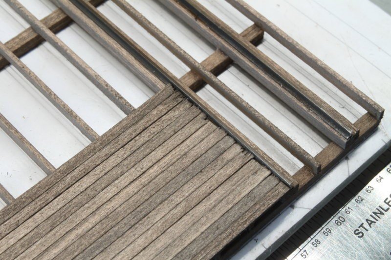
Welfack and Ken, thanks for the advice. I did a test by placing a plank between the rails covering the base and there was no interference with the wheel as it rolled freely down the track, so I'll forgo any spacer for the inner planks (the white plank seen in photo above) and have the boards go right up to the rail. I will post some in progress photos when I get to that part. Jeff
-
These photos were taken from a log on the SW forum and shows how the rails go on the planks. On the outside of the rail, the boards cover part of the rail base almost up to the rail. On the inner part a plank is used as a spacer to allow for the wheel flanges. I'm building a flatcar that will be incorporated into the diorama, so I'll see if there is enough clearance for the wheel flange if boards cover the rail base on both sides. It seems to me that if only half of the base is covered, the rail would be unstable. And a dock / platform like this does not seem to be an optimal location for spikes. I'll see if I get any answers from the SW forum. jeff
-
Thanks for the replies. Welfack, when I copied and pasted the post from the Sierra West Forum, initially the URL was seen and not the photos. I think you got to the post before I edited it as now the photos are visible. As far as where the planking ends at the rail, if it stops at the edge of the rail, then I would assume that you would then need spikes to hold the track down like you would have with RR ties. None of the build logs on the SW forum mention this. Re: comment by Canute, I was not implying to remove any of the rail base, but rather should the wood planking cover the flange part of the base up to the rail itself. The multiple planks would server to keep the rail anchored and obviate the need for spikes. I am not sure the wheel flanges would go low enough the hit the wood. I have a rail flatcar that will be part of the diorama so I may test this out. Jeff
-
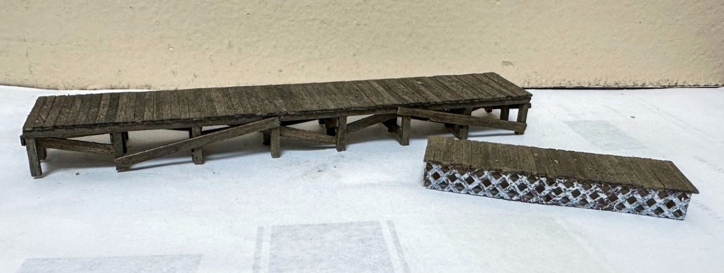
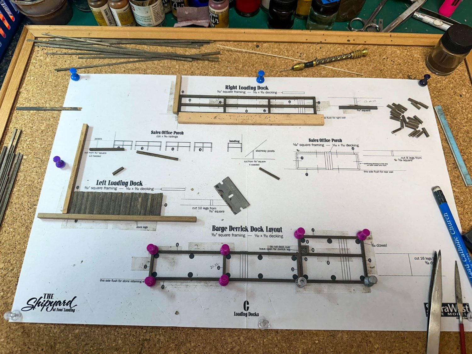
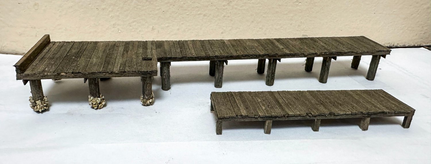
Greetings! Work continues with the docks. Template C has the right, left and derrick docks and the sales porch, all done simultaneously. Here is some early progress. The completed docks below. Instructions are very clear cut. Fine ballast was used to create the barnacles on the supports that will be underwater. One variation from the instructions - I decided to paint the skirting speckled white. I found that on many porches, this part was white. I'll probably make the railing white to match. This will be similar to the stairs and railing of Foss Landing. Note that on the derrick dock, I made the height of the "barnacles" less as the dock went inland as the water level would be lower. Now onto the main dock. Here is some preliminary work. I have a question for the any RR enthusiasts out there (not sure there are many here at MSW) - for the rails that are on the dock, where should I terminate the deck planking - at the blue line or red one? I can't seem to find many photos of this online and the pic in other build logs are too low resolution. As always, thanks for the kind comments and thanks in advance for any help on my questions. Jeff