Brinkman
-
Posts
154 -
Joined
-
Last visited
Content Type
Profiles
Forums
Gallery
Events
Everything posted by Brinkman
-
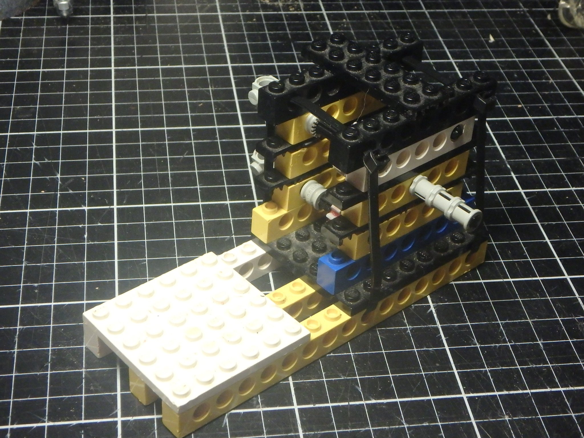
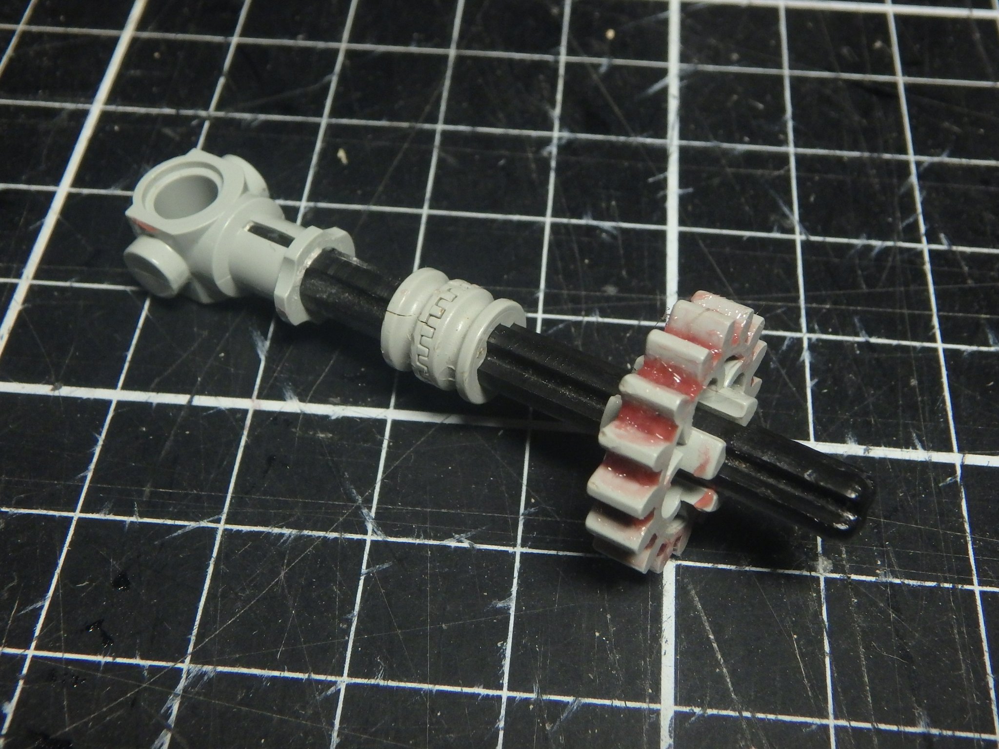
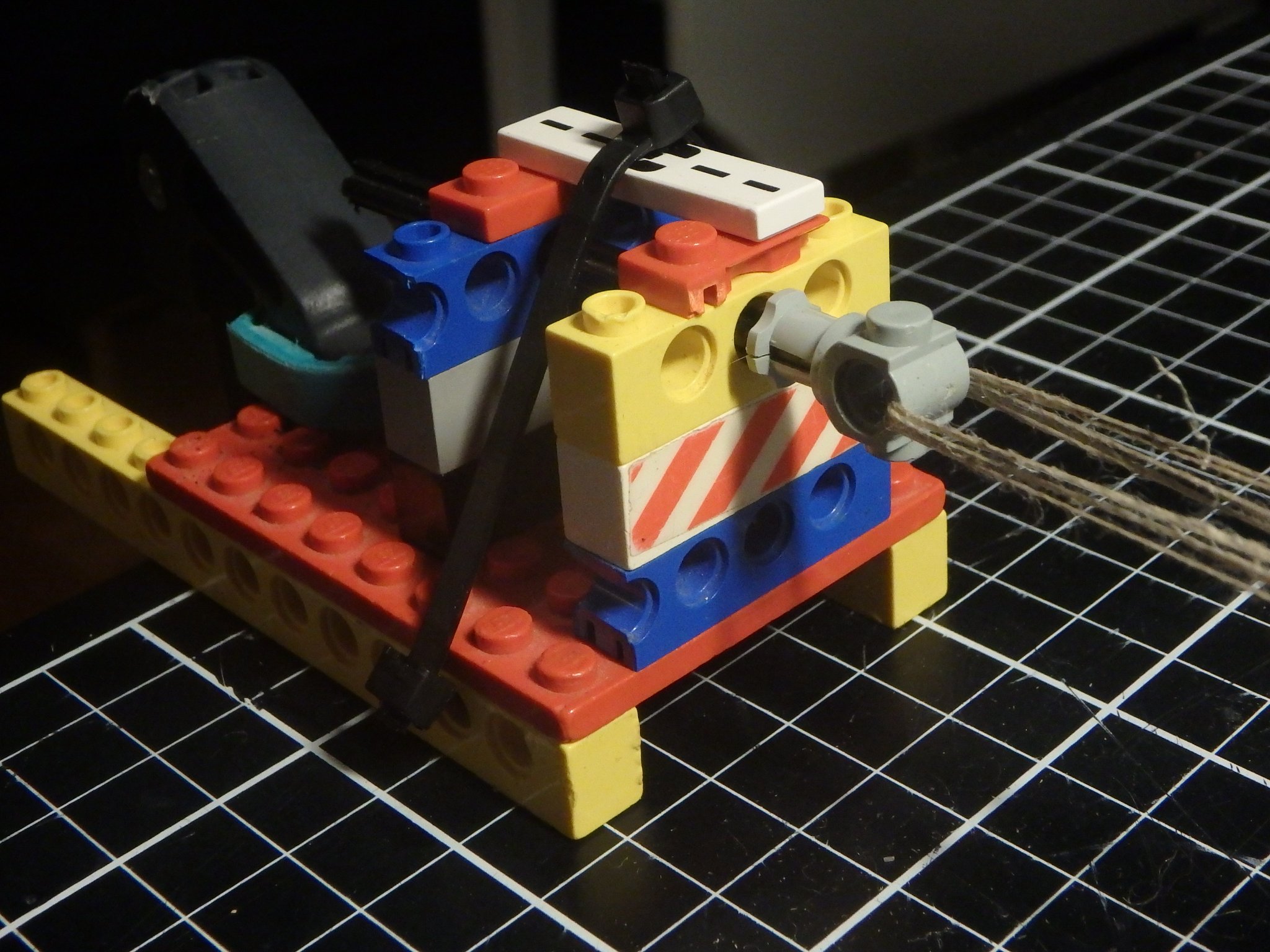
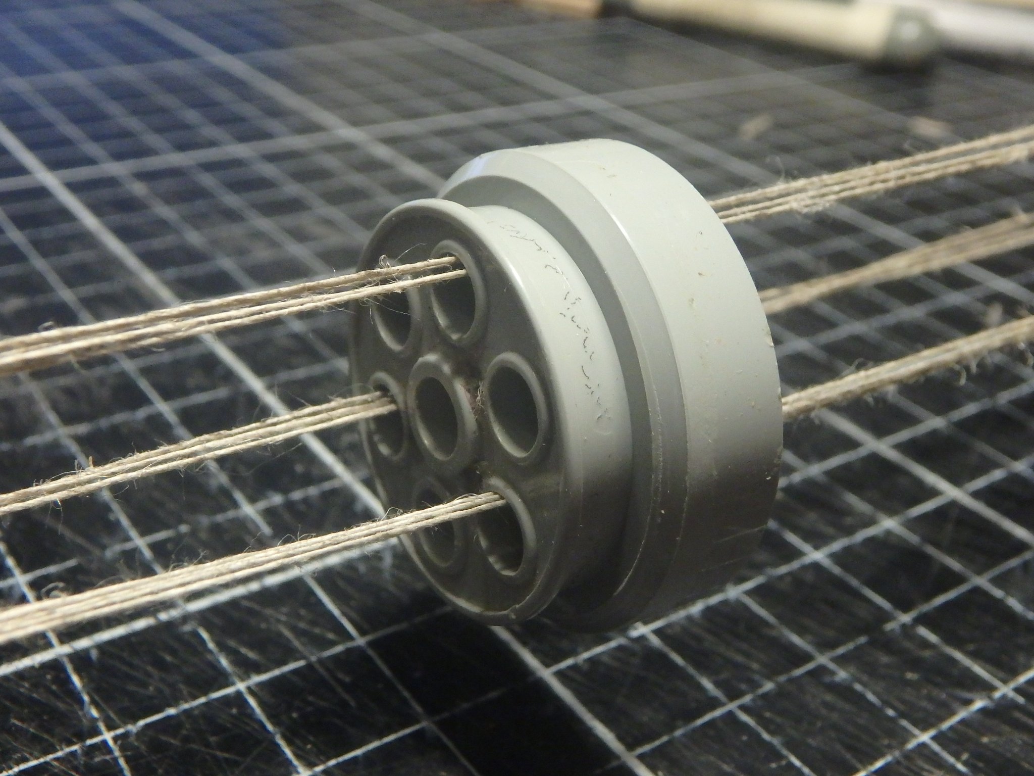
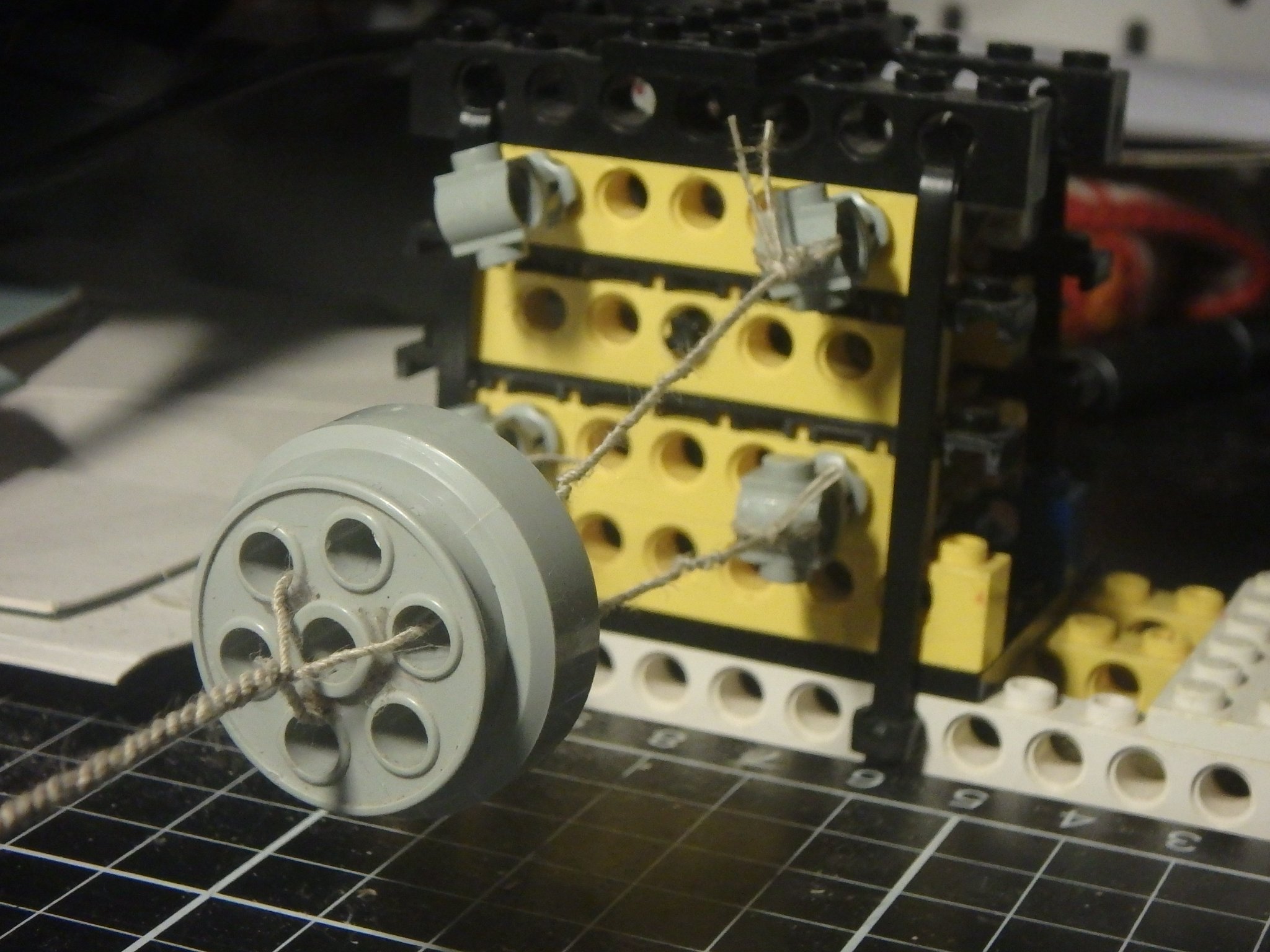
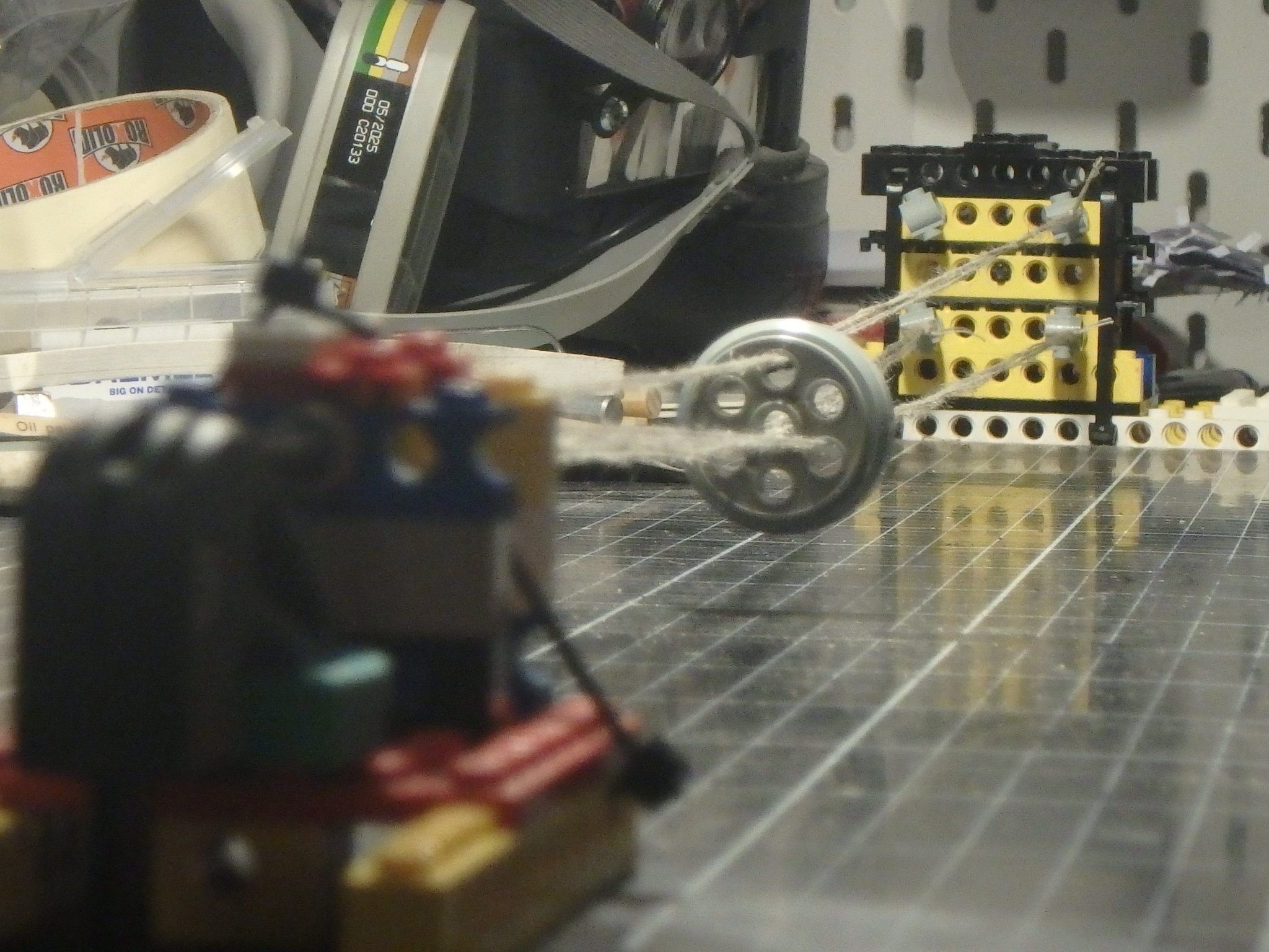
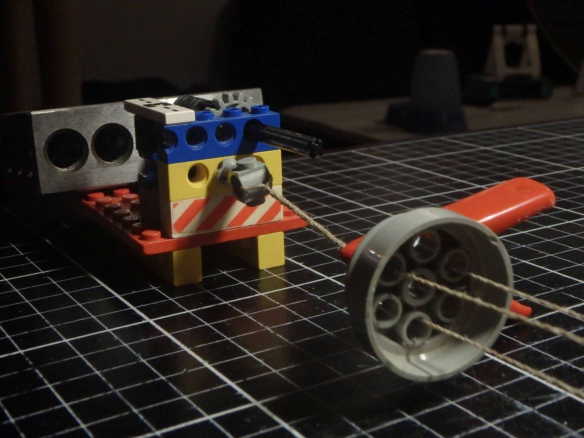
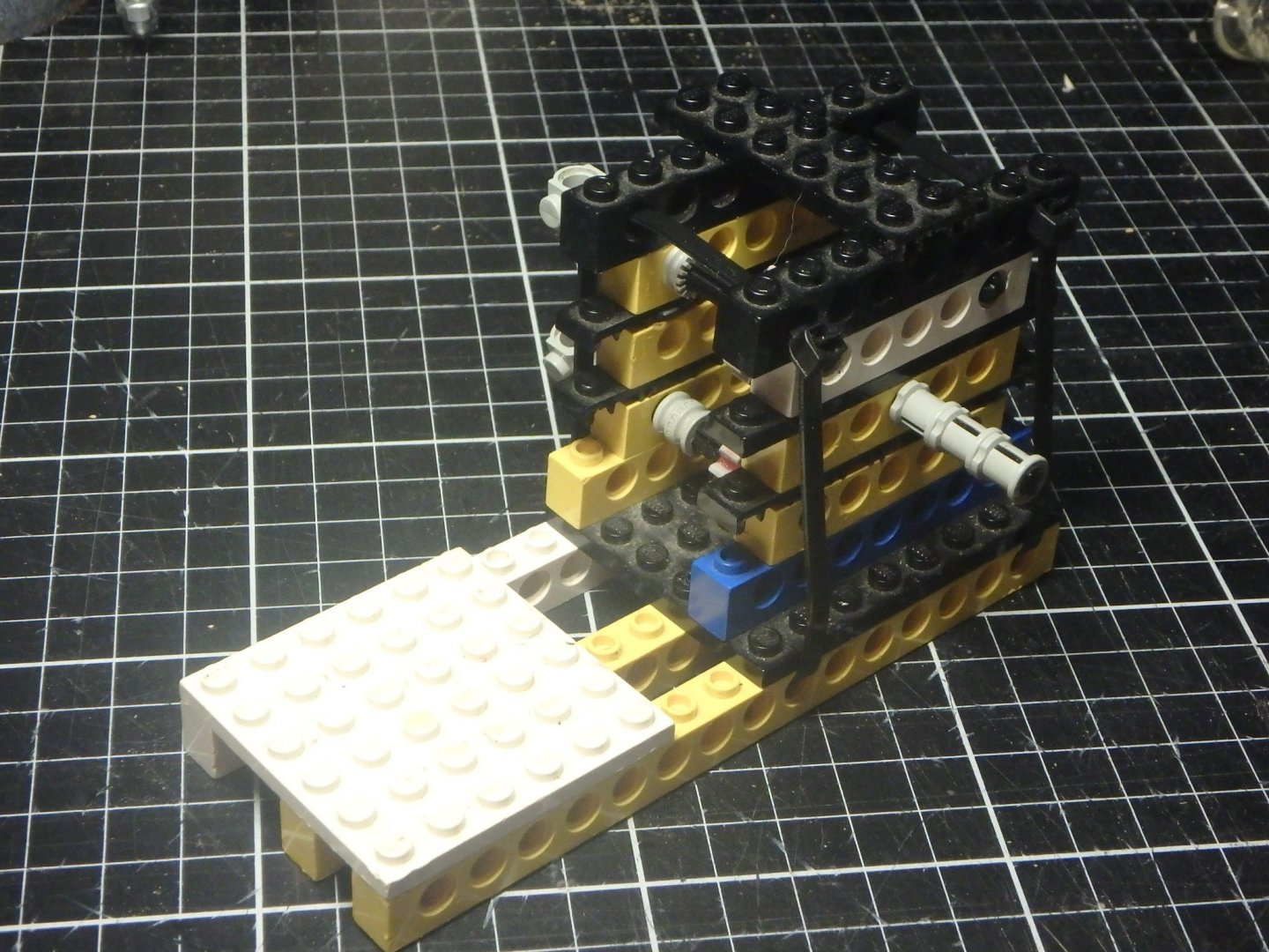
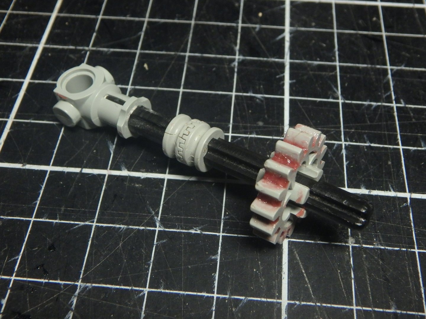
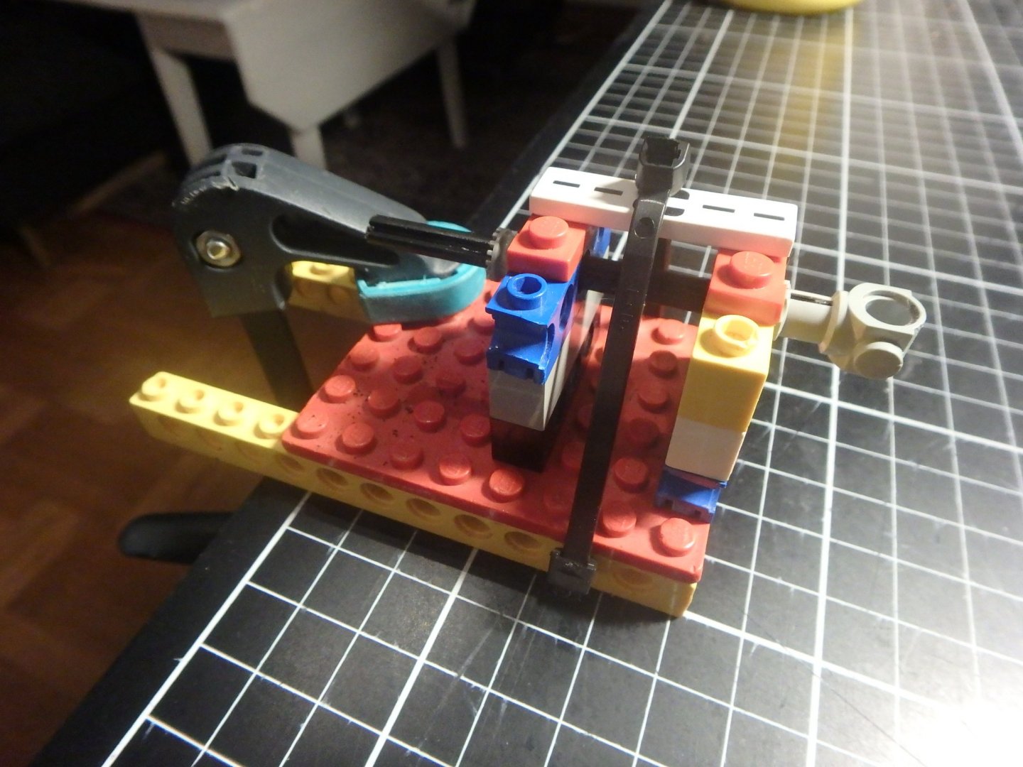
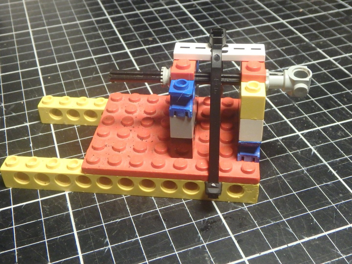
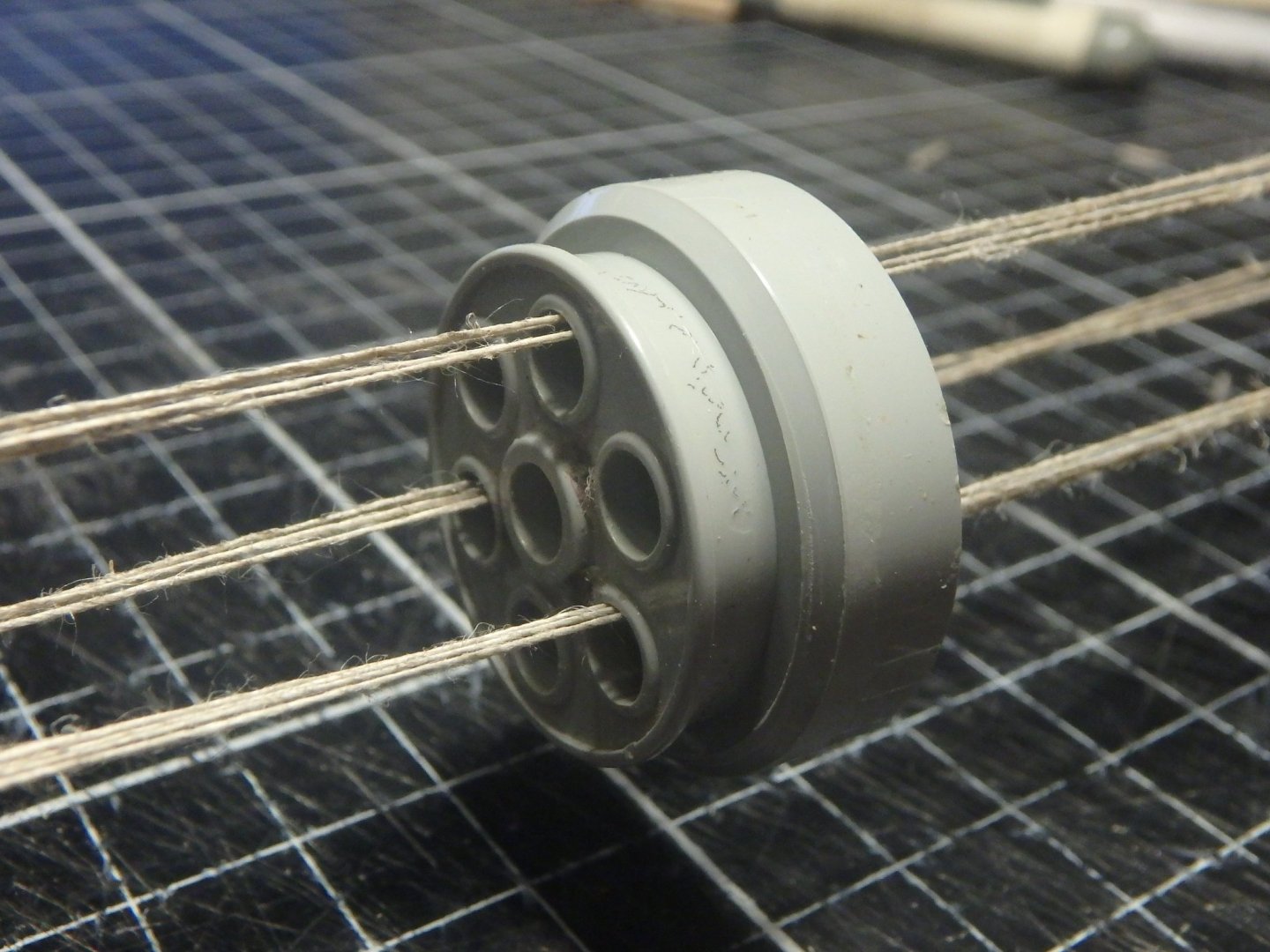
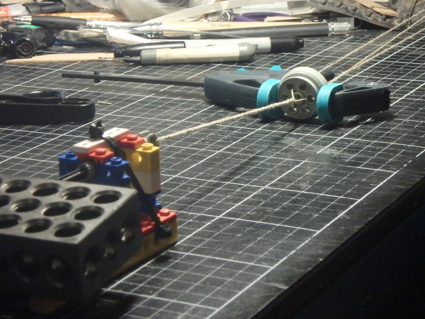
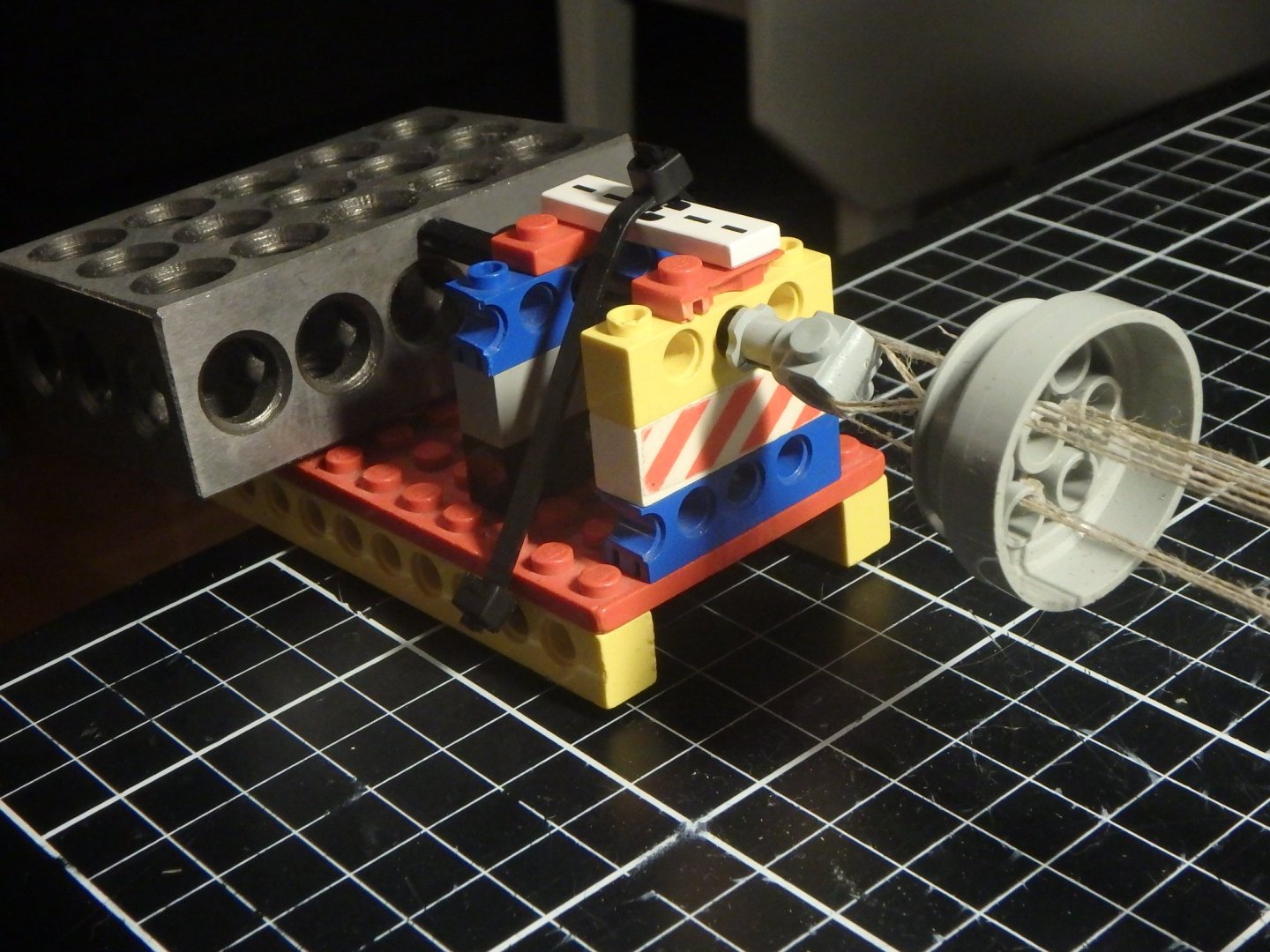
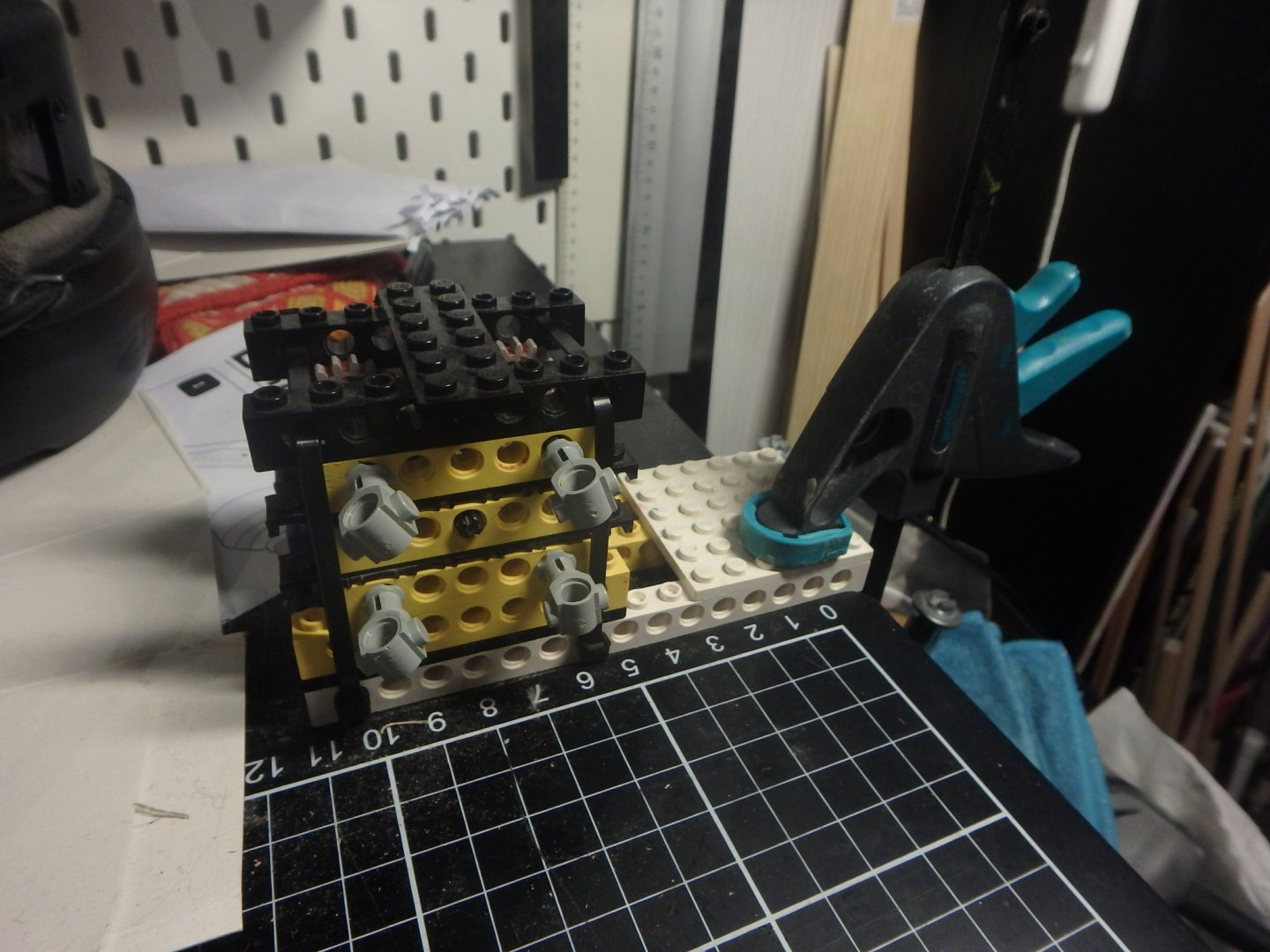
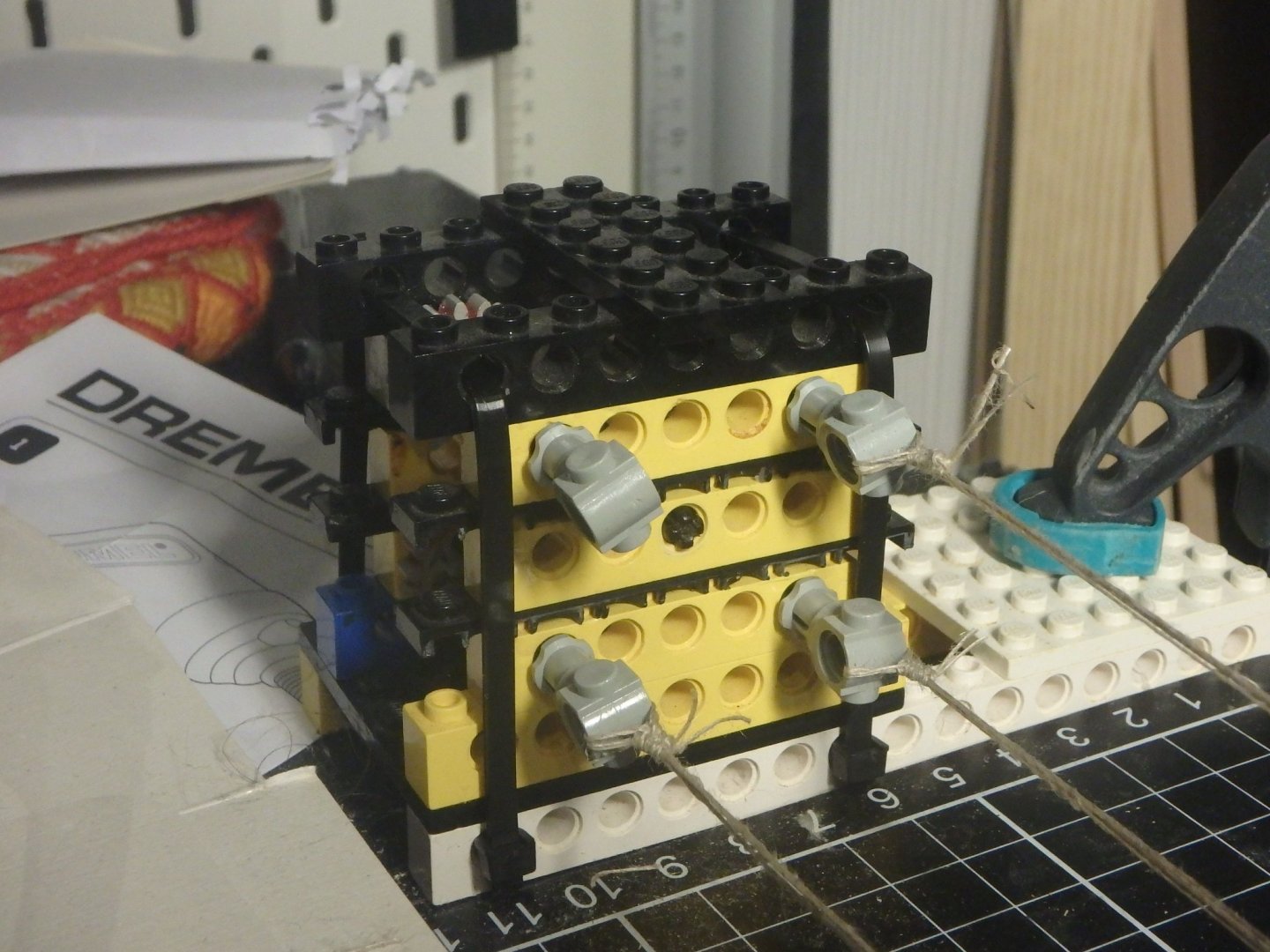
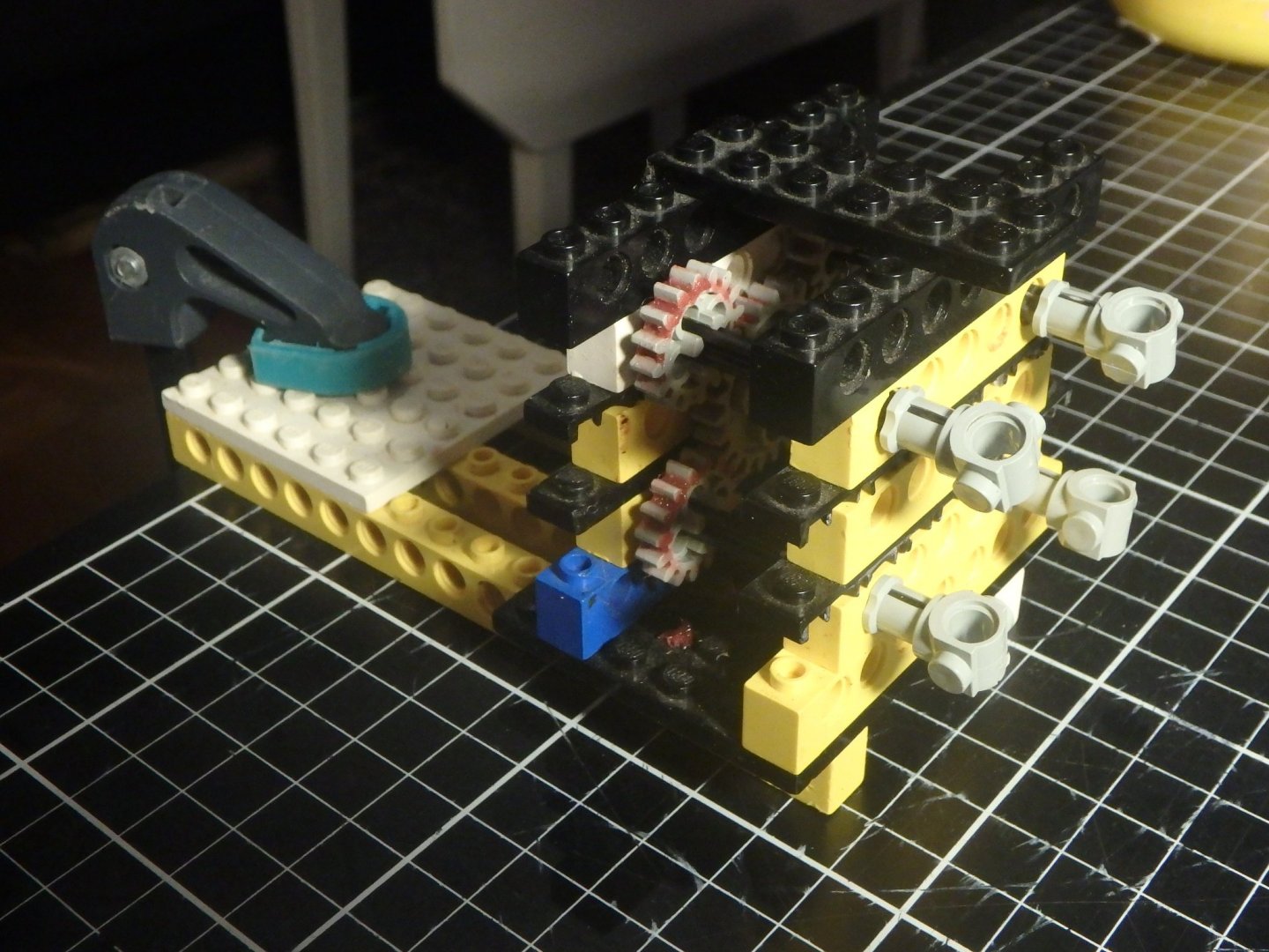
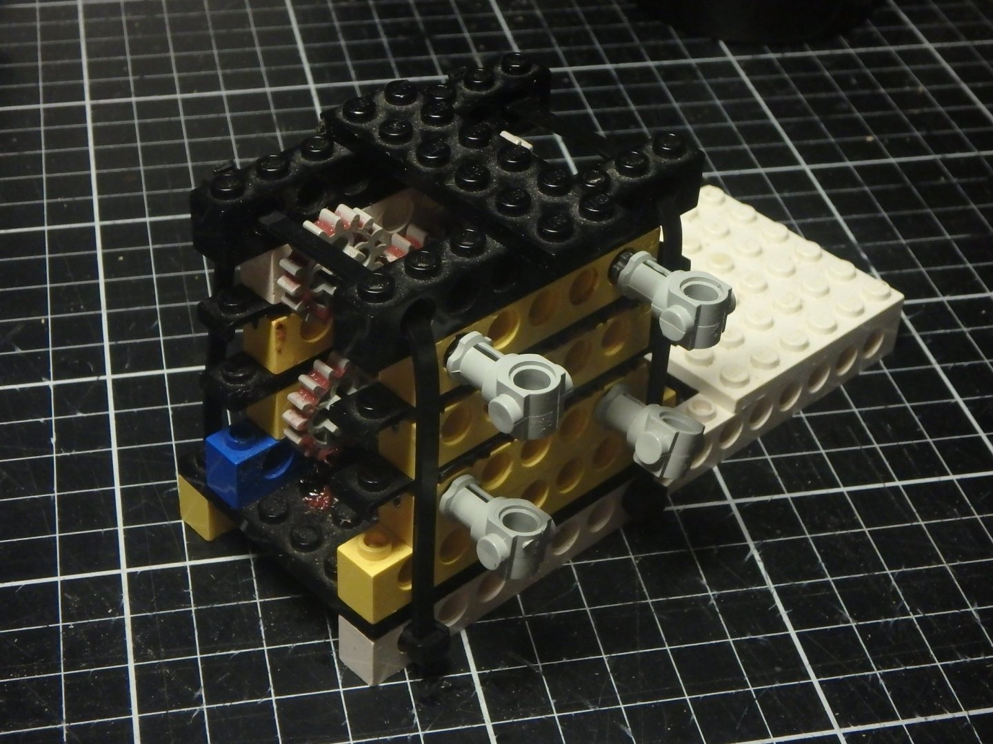
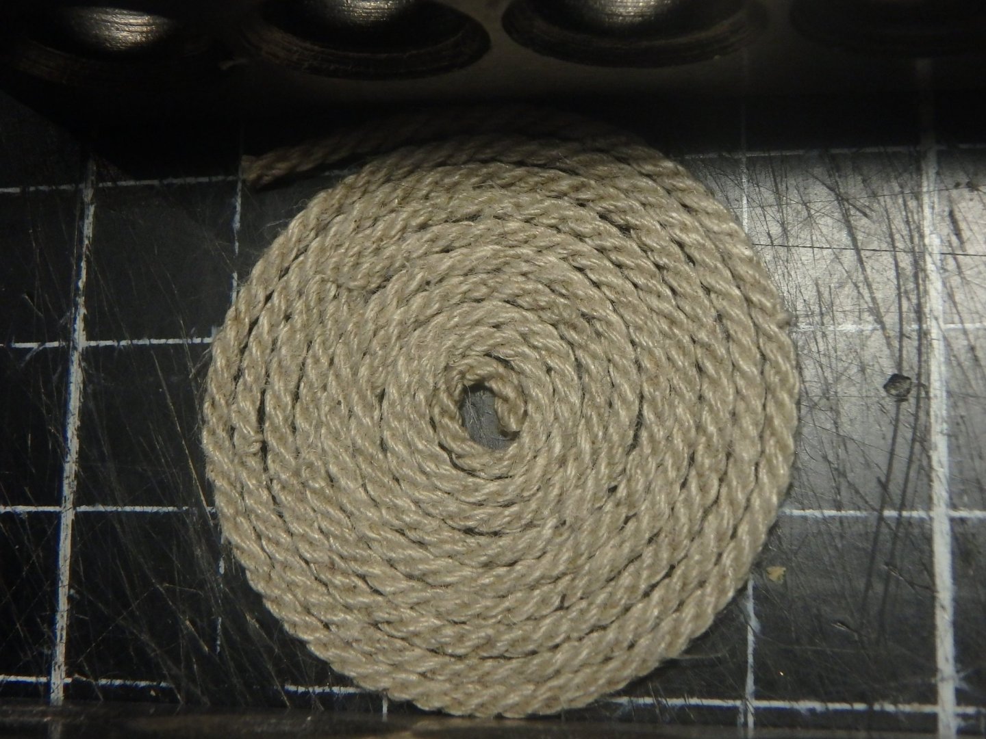
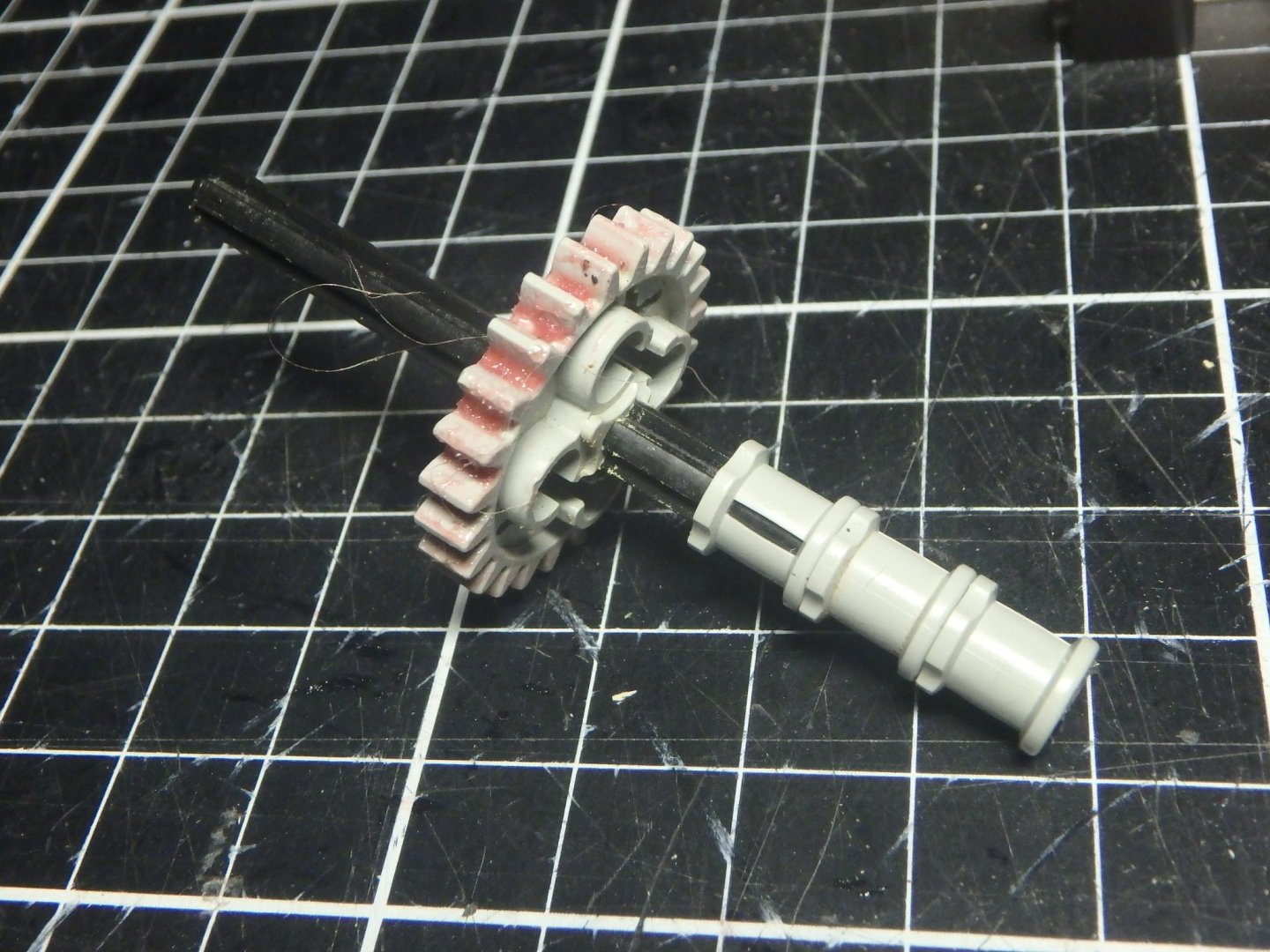
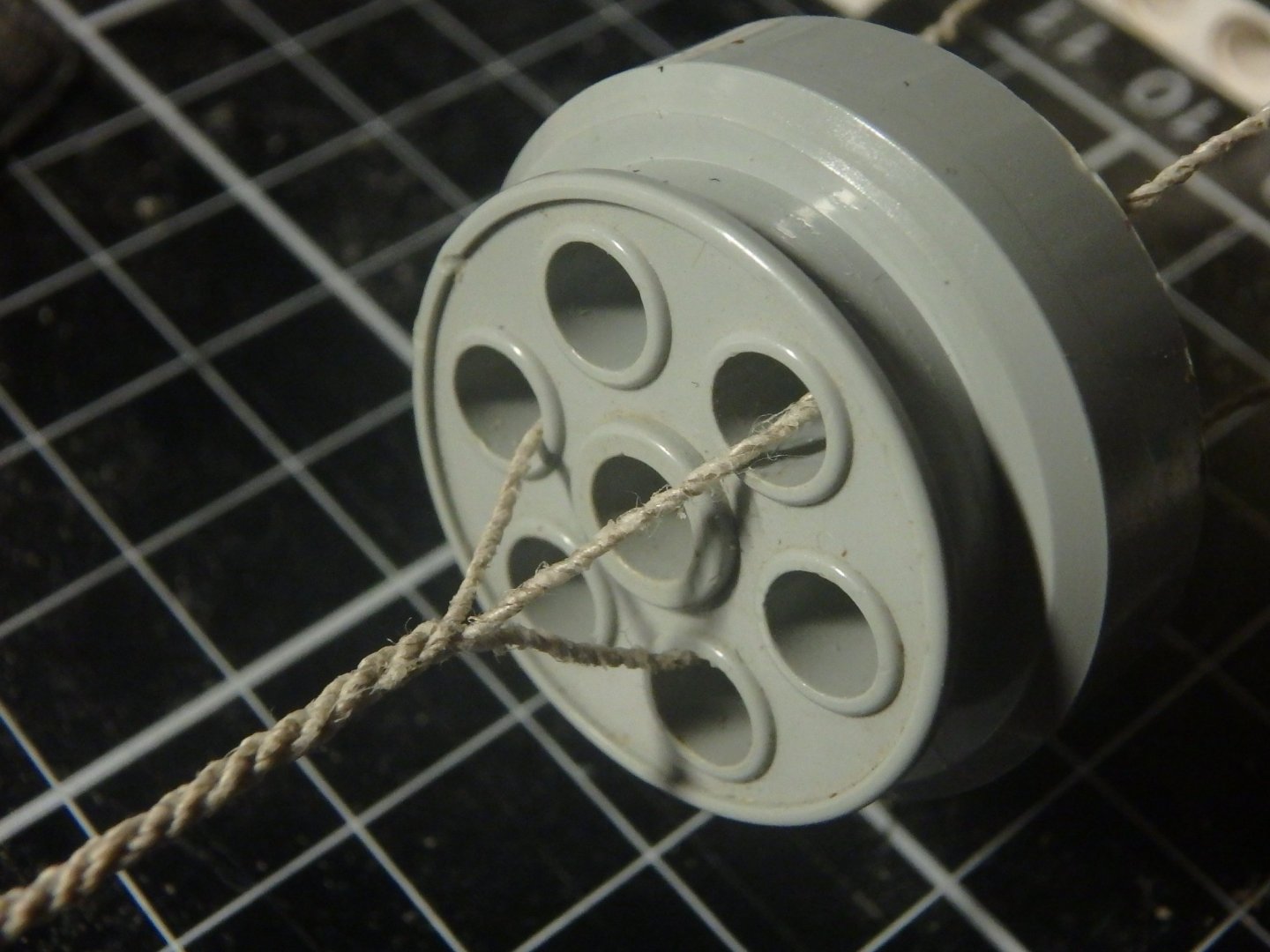
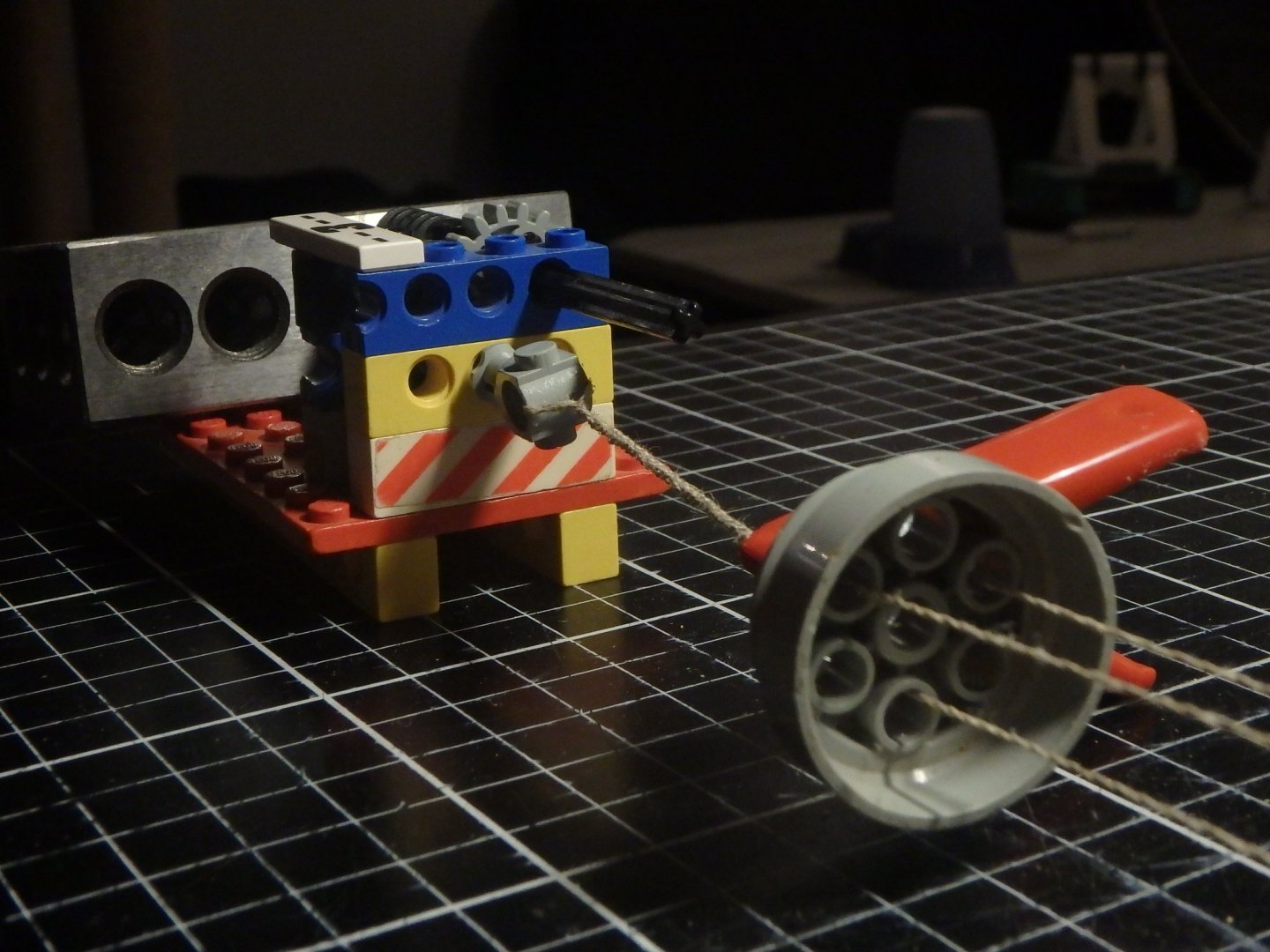
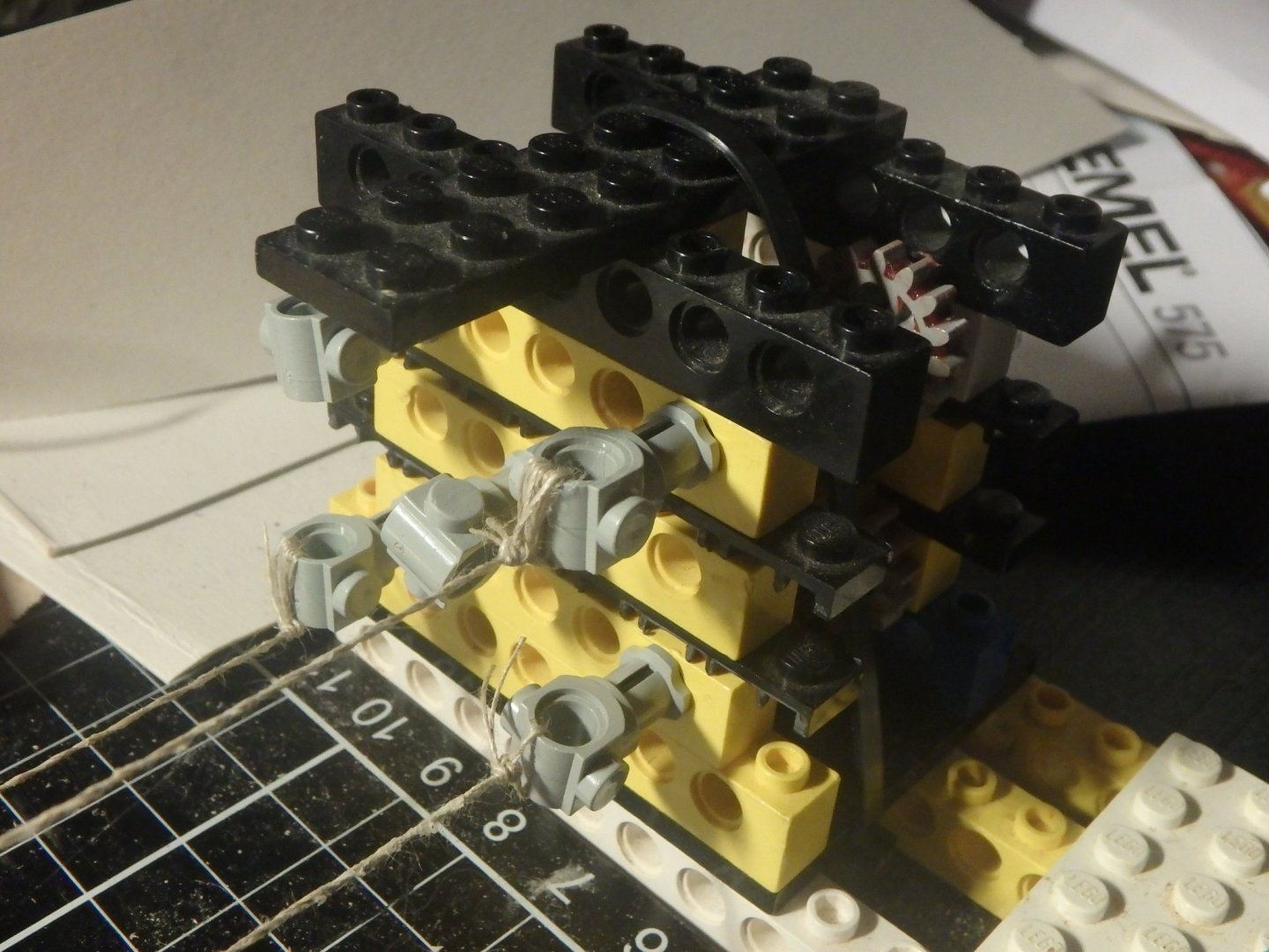
I showed my smallest ropemachine I built out of Lego in my buildthread and was asked for instructions on building it and thought that it would be good to create a new thread for it. There are many here with much more rope making experience then me, but I wanted to show this simple and cheap way of making ropes. Maybe someone else also gets bitten by the ropemaking bug. You can use this to make three or four stranded ropes up to a diameter of about 5mm, 3/16". I had a lot of Lego as a kid but got rid of it as I grew up so this is cobbled together with parts from a fleemarket and parts from a friend so it looks a bit odd. I havn't built with lego for over twenty years so you could optimize it a lot, but it gets the job done. And Lego Technic has apperantly changed a lot too, but this only uses old parts. I used LegoLink for reference and it seems to be lots of shops where you can buy individual bricks. https://www.bricklink.com/ Sorry for the red goo on the gears but grease makes it run better. This is the main unit It has four axles that each consists of 1x Technic, Axle 6 1x Technic, Axle and Pin Connector 1x Technic, Gear 16 Tooth 2x Technic, Bush 1/2 Toothed Type I Superglue the connector to the axle. The drive axle 1x Technic, Axle 8 1x Technic, Gear 24 Tooth 3x Technic, Bush The superstructure 10x Technic, Brick 1 x 8 with Holes 4x Technic, Brick 1 x 16 with Holes 3x Plate 6 x 8 4x Plate 1 x 8 The changes I did with this list compared to my build is that the width of the standing part is unified and has a better roof. There is an extra beam in the base. Use cable ties to hold it together. On the other end of the ropewalk we will have the sleigh (I can't find the english word for it now, but I think this is what it's called in swedish) that is built from 4x Technic, Brick 1 x 16 with Holes 6x Technic, Brick 1 x 6 with Holes 2x Plate 6 x 8 1x Plate 4 x 6 1x Technic, Axle 8 2x Technic, Bush 1/2 Toothed Type I 1x Technic, Axle and Pin Connector The changes here are a longer base, wider standing part, a better roof and an extra beam in the base. Use cable ties to hold it together and again superglue the connector to the axle. The rope comes together at the top that is a Wheel 30mm D. x 13mm (13 x 24 Model Team) But you could use anything with preferably six equally spaced holes. Using the ropemaking machine This is just a really quick guide and just like always - practise makes perfect. Please also watch videos of how people do this. Clamp the main unit to the table, you can do this either like this Or this by rotating the standing part like this Clamp the sleigh to the table Tie up the strands using thread. You can use any number of of threads per strand, but it requires a bit of practise to use a single thread in a strand. Thread the threads through the top. Each strand is tied to _one_ "hook" on the main unit, goes through _one_ hole in the top and all strands connects at the sleigh. Remove the clamp on the sleigh and replace it with a weight. The size of this depends on the thickness of the rope. Now the ropemaking can start. Move the top to the sleigh. Turn the drive axle on the main unit. This twists each strand. Hold on to the top to prevent it from rotating. The strands will get shorter as they twist and the sleigh will move. Twist the strands until you see that the strands wants to twist together on the far side of the top. Continue twisting the strands and begin to move the top away from the sleigh. The sleigh hook will start to turn and the strands twist into a rope. It is tempting to twist the sleigh hook too much and thus twist the rope, but it is important to let twist come from the strands. But sometimes you need to also help the twist from the sleigh side. Too much turning on the main unit will make the strands knot and too much twisting from the sleigh will make rope that unravels. Perfectly balanced rope does not unravel when cut. Continue until the whole rope is formed. And stretch the rope well when it is finished and cut from the ropewalk. This rope for example strecthed from 53cm to 58cm. The strands were 82cm before twisting. Its good to wax the rope if it will not be painted and I like to wax the strands with beeswax before the rope is formed. Please ask questions as I see how unclear this long post became...


- 5 replies
-
- 20
-

-
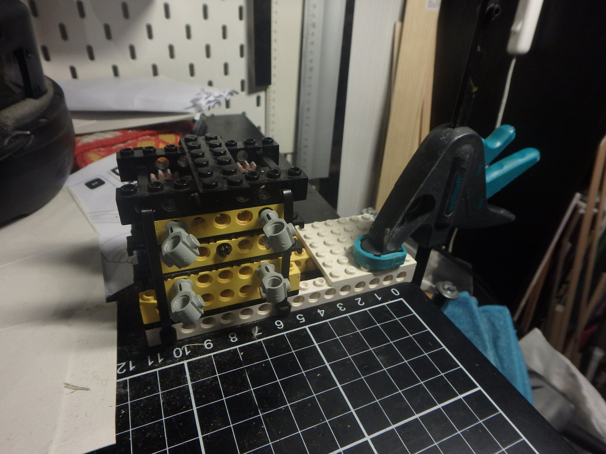
 Thanks you for the comments! The ropemaking machine is a really simple build and looks like this on the inside. The red goo is grease. I regretfully got rid of my childhood lego a long time ago and bougth most of this at a fleemarket (they had a big bag for $30 and I just took what I wanted and gave back the rest, the money went to a cat shelter so it was ok) and got some parts from a friend. You can nowerdays buy just the parts you want from some vendors and I could make a partlist if someone wants it.
-
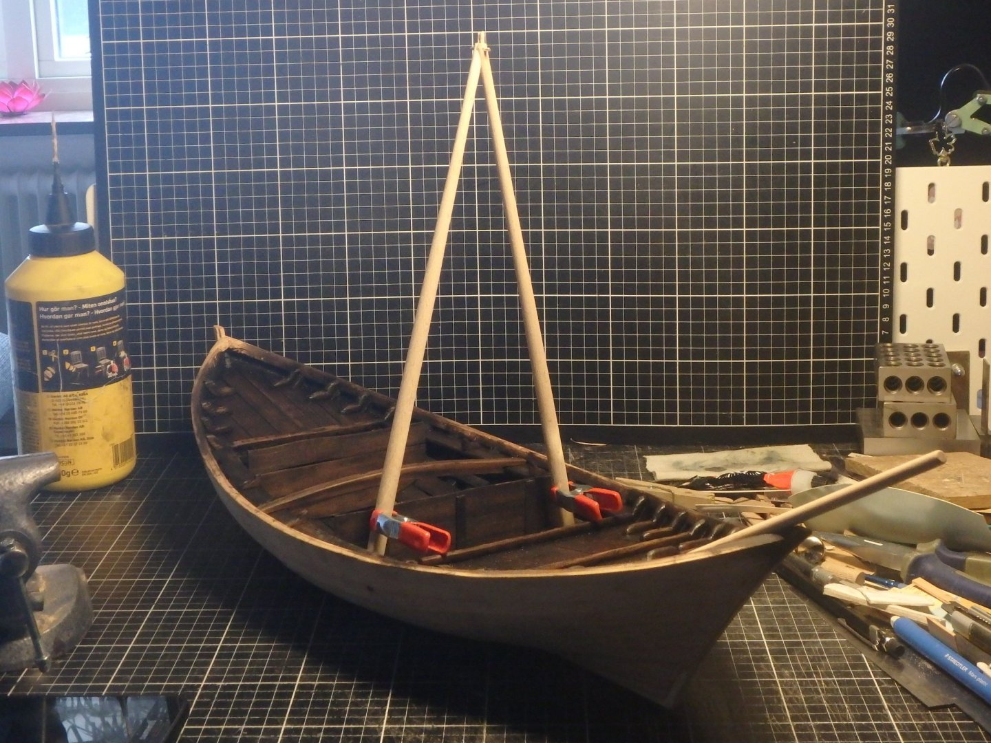
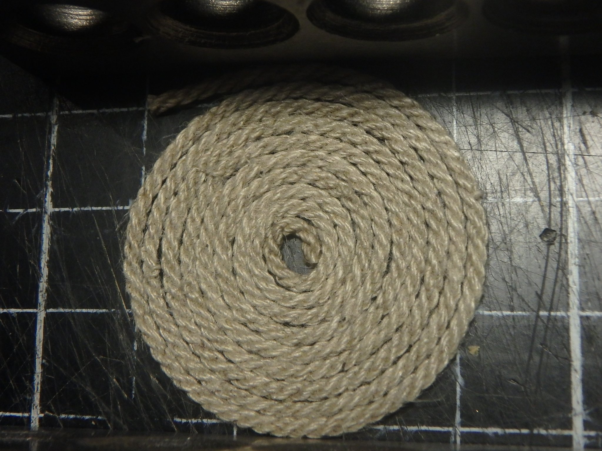
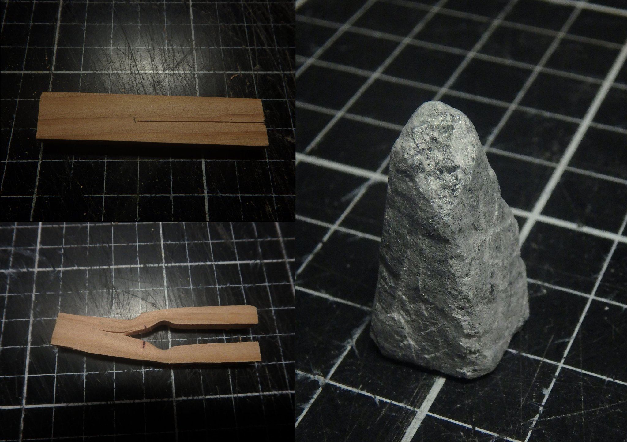
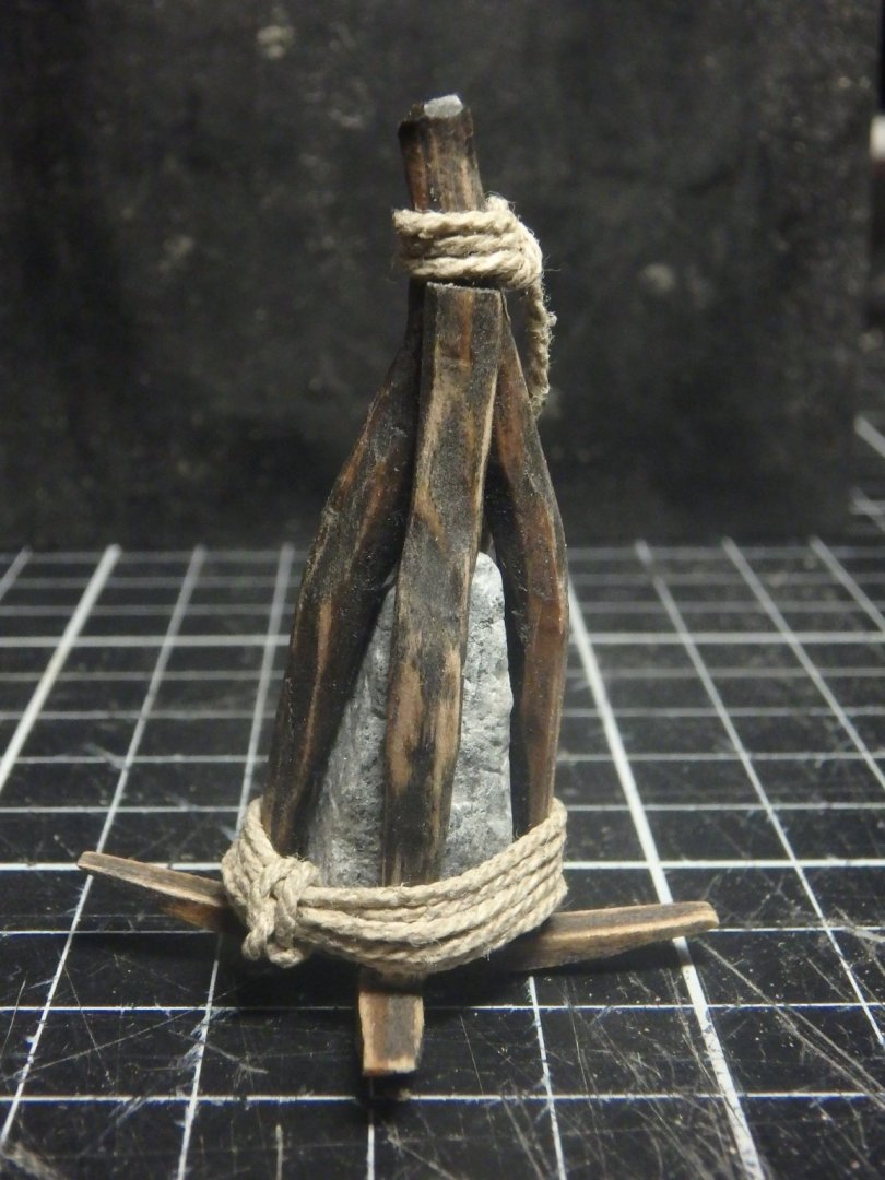
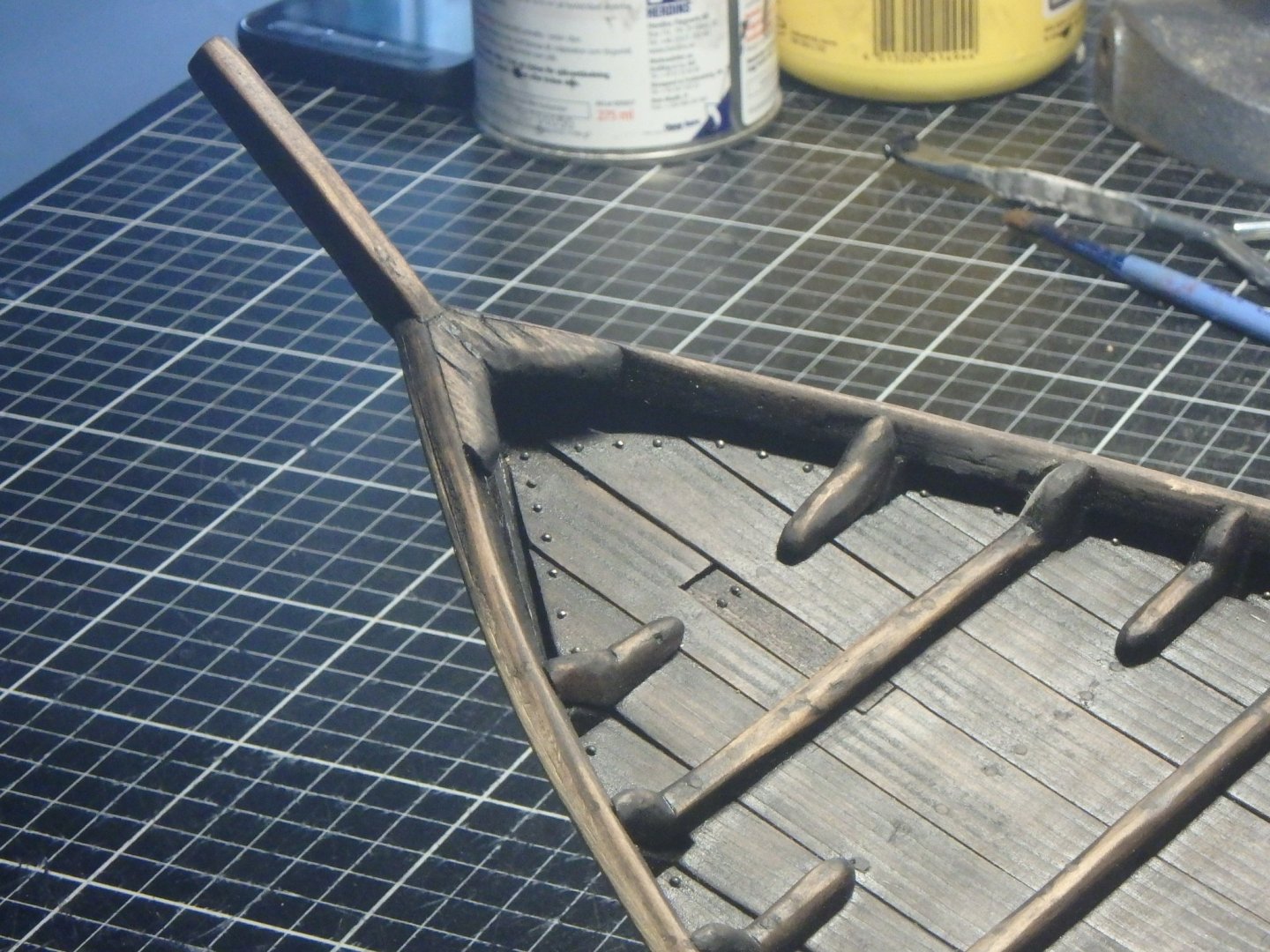
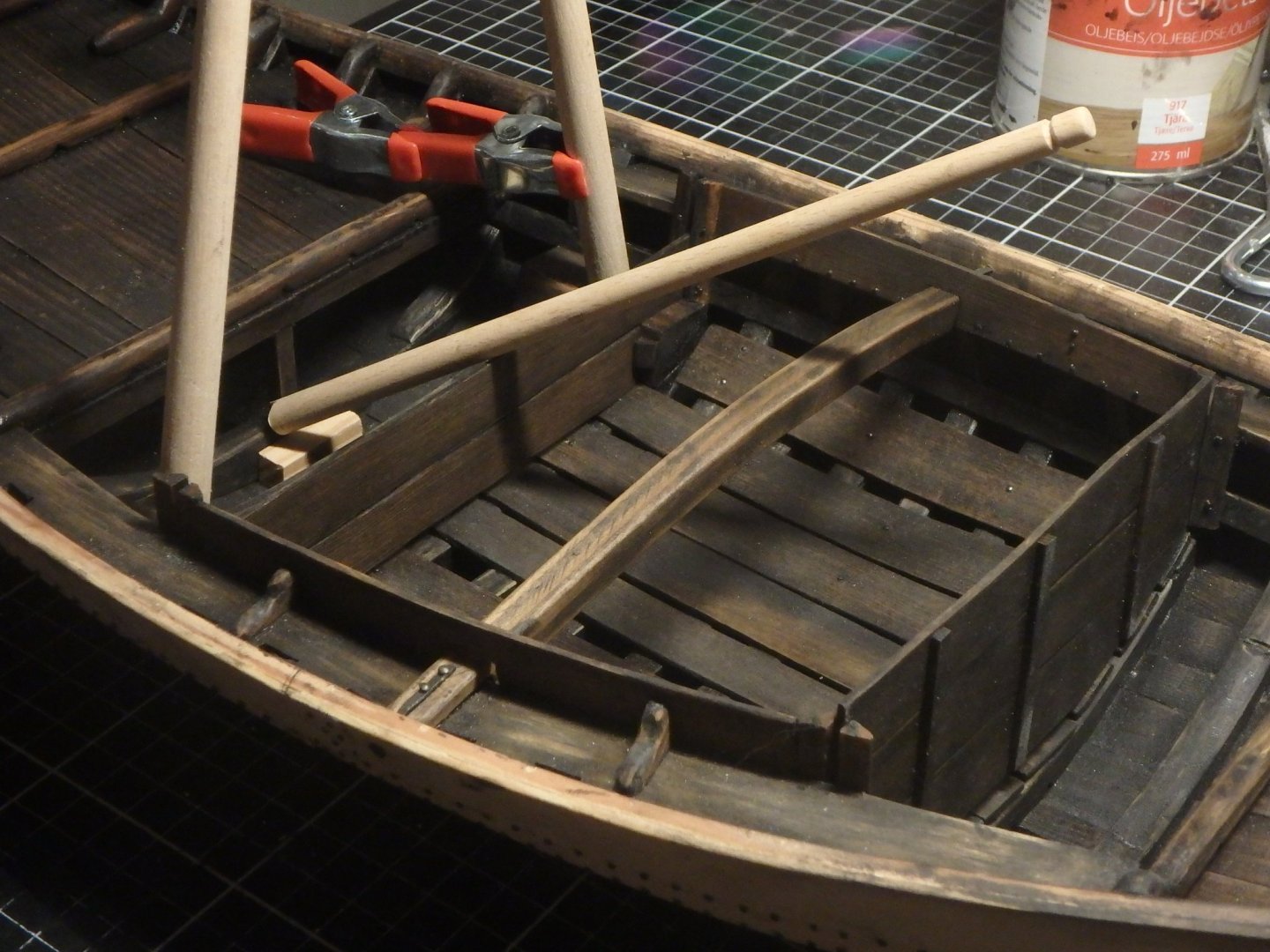
I was intrigued by the use of carving stone by the egyptian fellows here and I wanted to try it out so my secondary anchor is a stone anchor. A wreck of a similar cog to mine was found with a bit of wood with a strange shape that the author of a thesis thought could be a bit of a stone anchor and Kalmar 1 from 150 years before my ship had one. But they were used in Sweden and England well into the last century so I guess I could have one as well. I tried to copy the one from Kalmar 1 that looked like this. I bent a bit of wood to form the crotch. I think my stone would weight about 30kg in real size. It can be stored under the aft deck. The rope was made on a small lego ropewalk I built a couple of years ago The rope is made of six linen threads and waxed with beeswax.
-
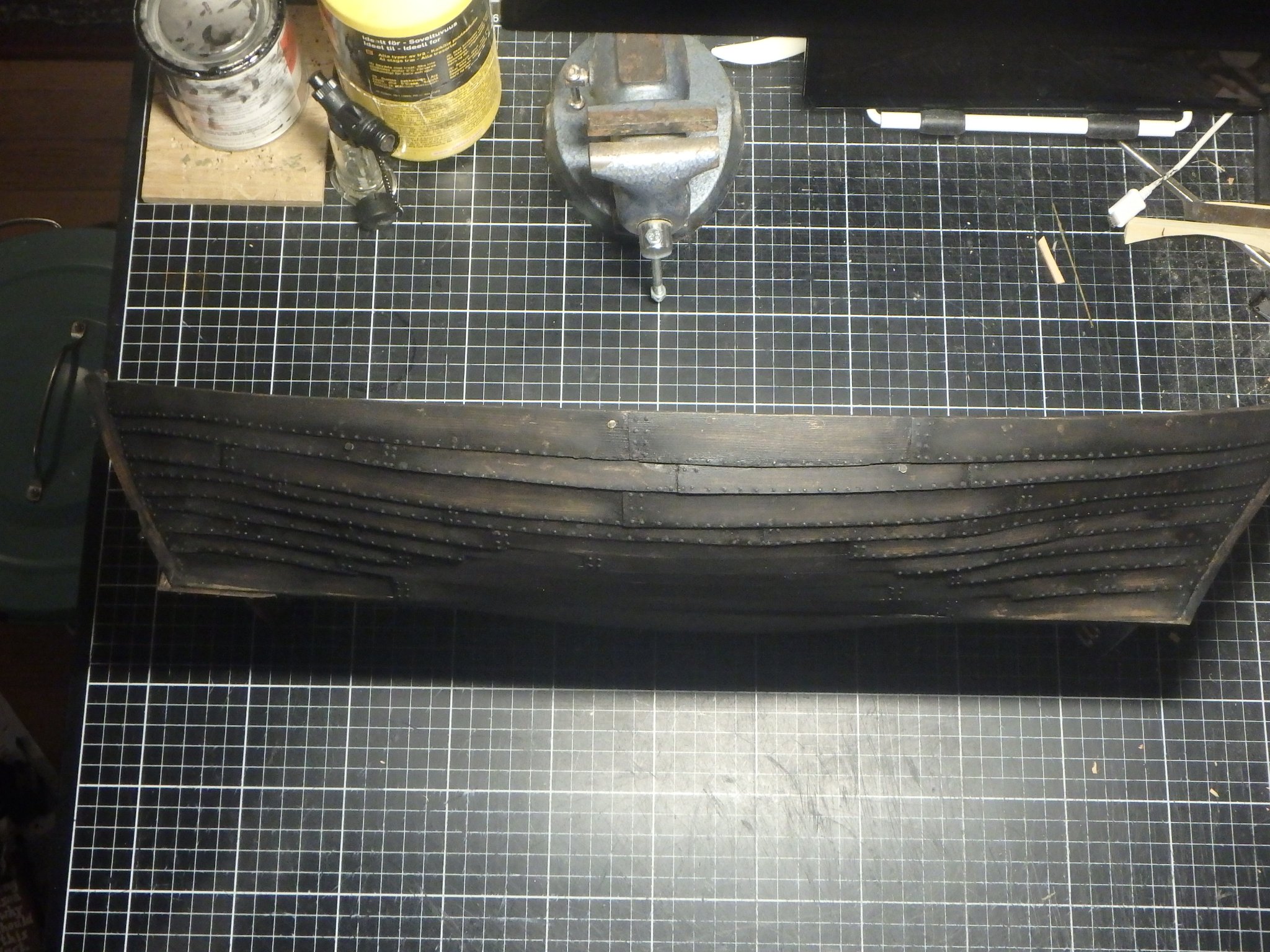
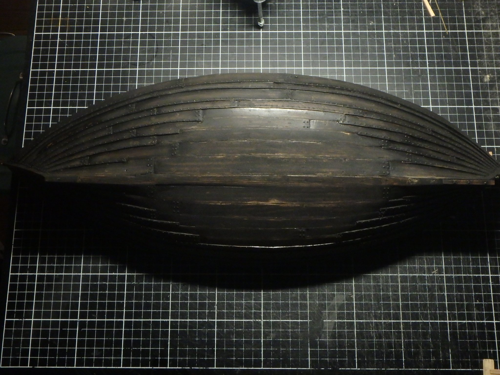
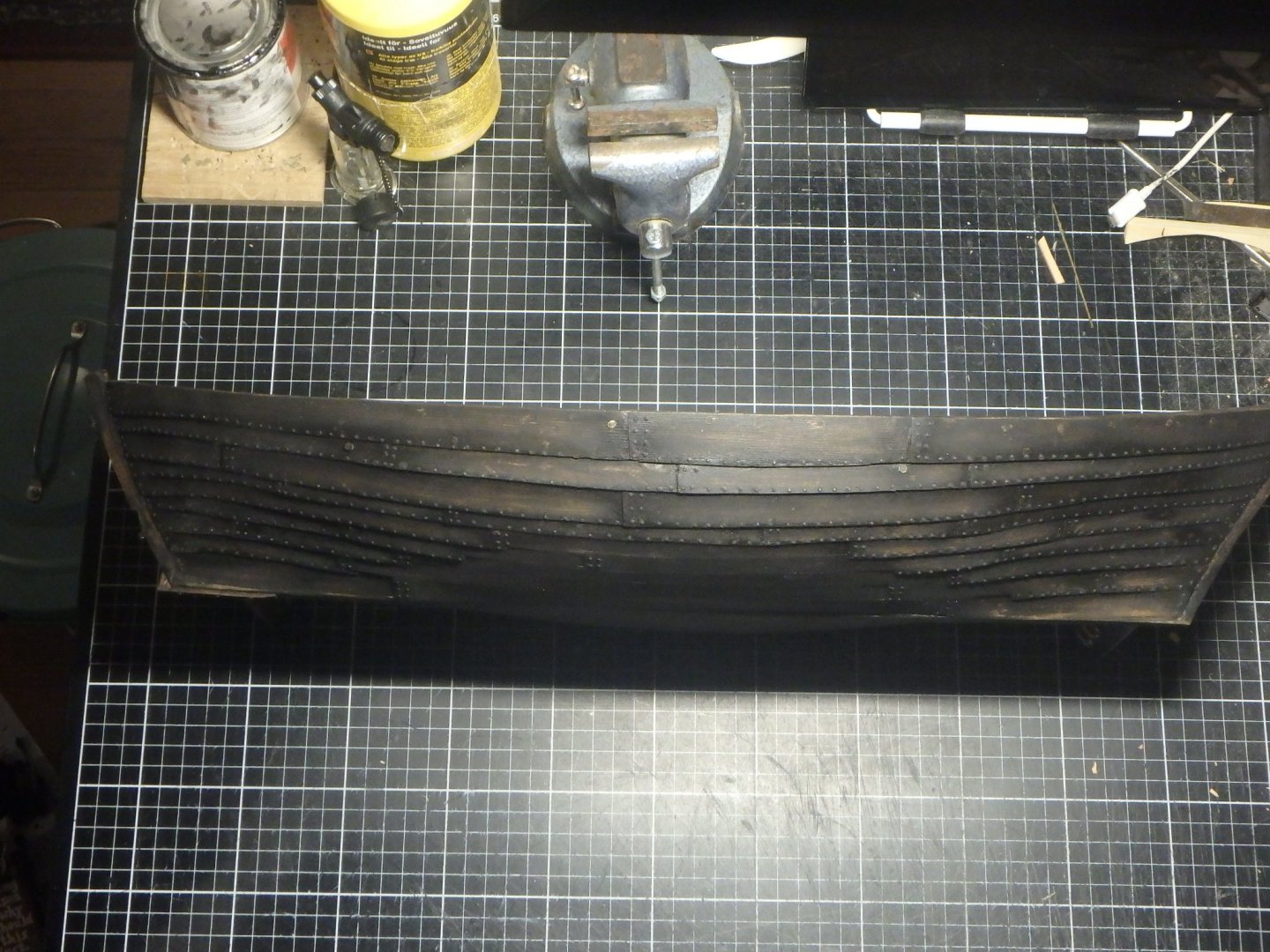
Thank you all for the nice comments! I started nailing the hull almost a month ago and it has taken time as it is over a thousand nails. I have done other areas inbetween as you have seen and I really liked the outcome of the nailing of the decks so I looked forward of the hull being completed. But when the last nail was set and the painting started it looked all wrong. The paint got blotched! I did just like before; painted and after a wait I wiped off the excess and then used steel wool. But the nails was a dabbed in cyan glue and of course small speckles of it got on the planks and the paint didn't stick there. It looked awful. Then it hit me. The decking was first painted, then nailed and then painted again meaning that you didn't see the blotching because of the first layer of paint. So I covered the hull in a thick layer of paint and let it dry for three days and then went over it with steel wool to create highlights. Which polished the nails. So I painted them in a really flat black paint. The impression I have been after is the viewer to first look at the planking and after that notice the nailing. It's a bit blotchy but good enough for now. Over to anchors. The ship will have a main anchor (I guess it can be called a sheet but it feels wrong for such a small vessel) and a smaller secondary anchor. There are very few medieval anchor finds and the wreck this is based on didn't have one; maybe it was salvaged as it was just a few meters of depth there. But the literary sources say that large ships had several and images also show smaller vessels with them. And the wreck of a similar ship to this had a small piece of an anchor, a fluke, in it. But what size? Two sources, a dutch and a british in the the 17th and 18th century, said that the anchor length should be 2/5 of the ship's beam making mine 1.6 meters. A 10 tonnage ship should according to an 19th century source have a 53 kg anchor and another source from the same time says that an 51kg anchor should be 1.7 meters. It's really good that all three sources converge at the same length, but that's awfully big. I guess this is for seagoing vessels. A modern source gives 2 pounds for each foot of waterline which would make mine 30kg. I guess I will have something in between. I have already started on the smaller secondary anchor which is a really fun build and more about that in the next post. I'm writing these long winding posts as I think my girlfriend is sick and tired of all this talk about ships and anchors...

-
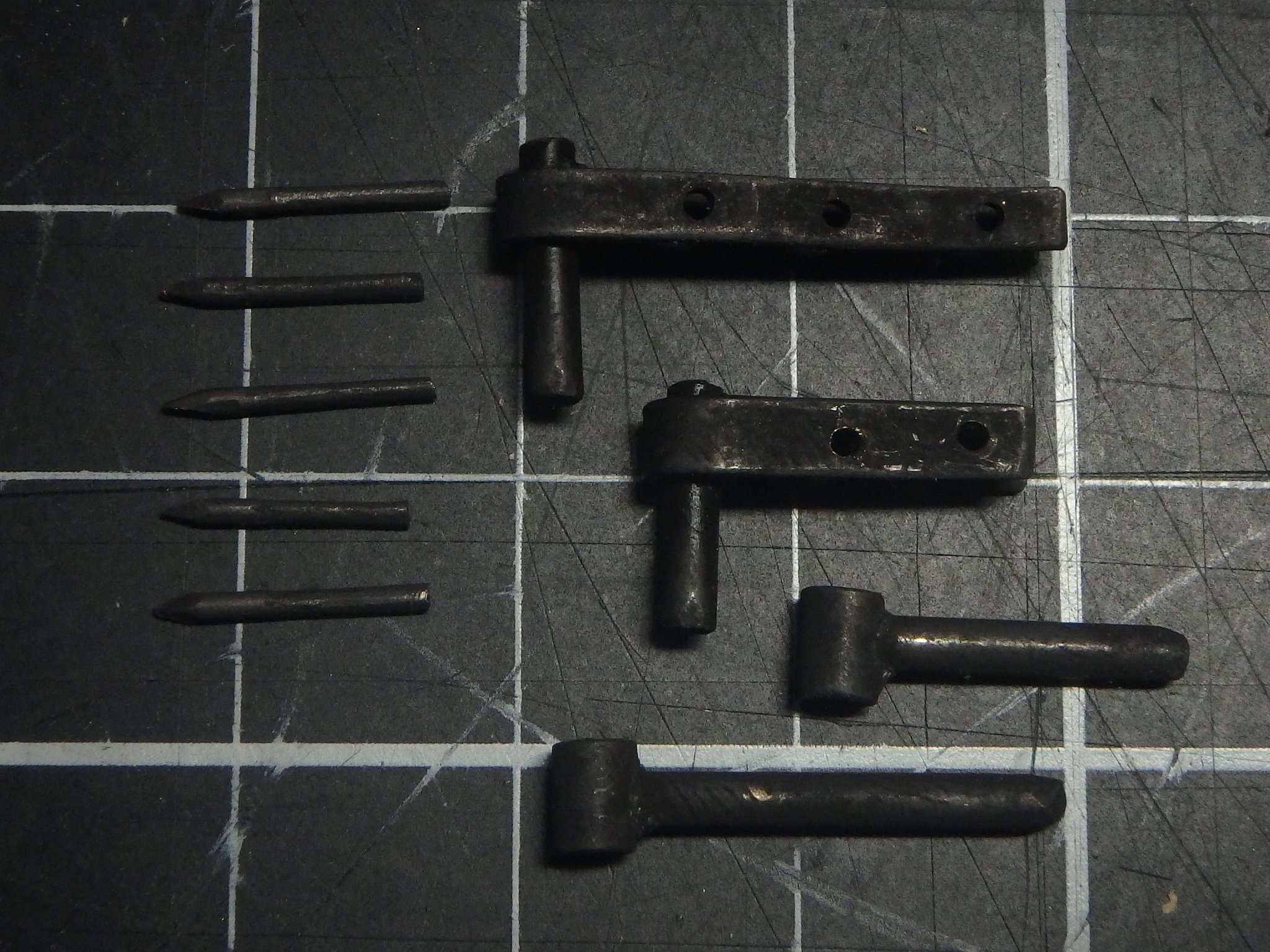
Thank you so much Ab, Chuck and Steven! Perhaps the nails after all looks better than I thought. The windlass is from a book I found when reading up on anchors. It's "Fartygsfynden i den forna hamnen i Kalmar" (The ship finds in the old harbour of Kalmar) by Åkerlund, 1951. It describes many finds and has really good plates in the end with drawings. The book is in swedish but has a seven page summary in English. Anyone can just ask me if you want something translated or clarified. The book can be downloaded here https://sjohistoriskasamfundet.files.wordpress.com/2017/08/skrift05.pdf The author built models of the finds that can be viewed here https://digitaltmuseum.se/search/?q=Fartygsmodell+medeltid But I'm not a big fan of the details as I think they borrow a bit too much from much later ships to be fully convincing.
-
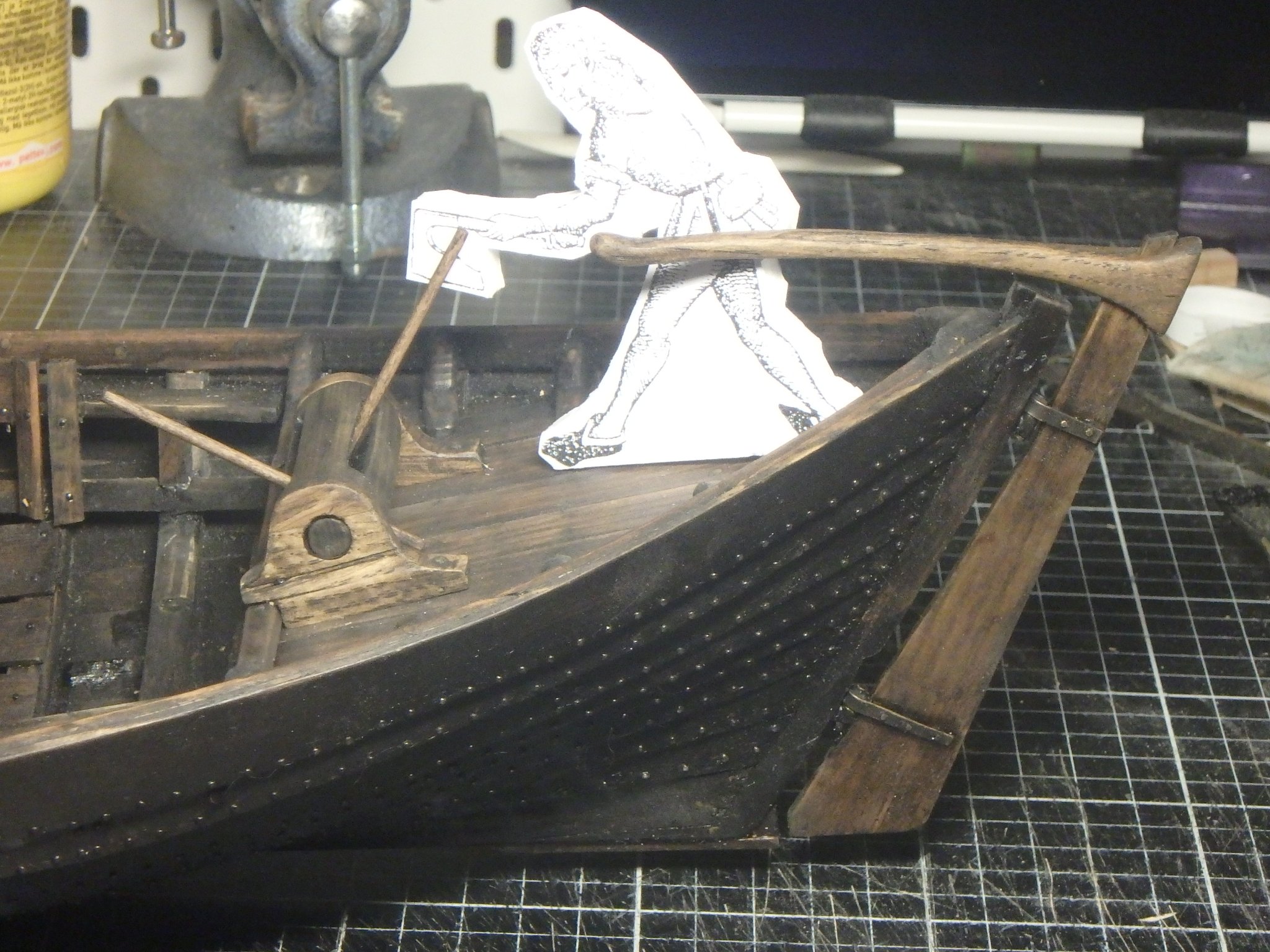
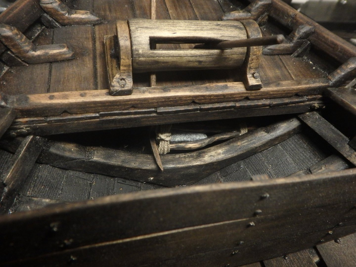
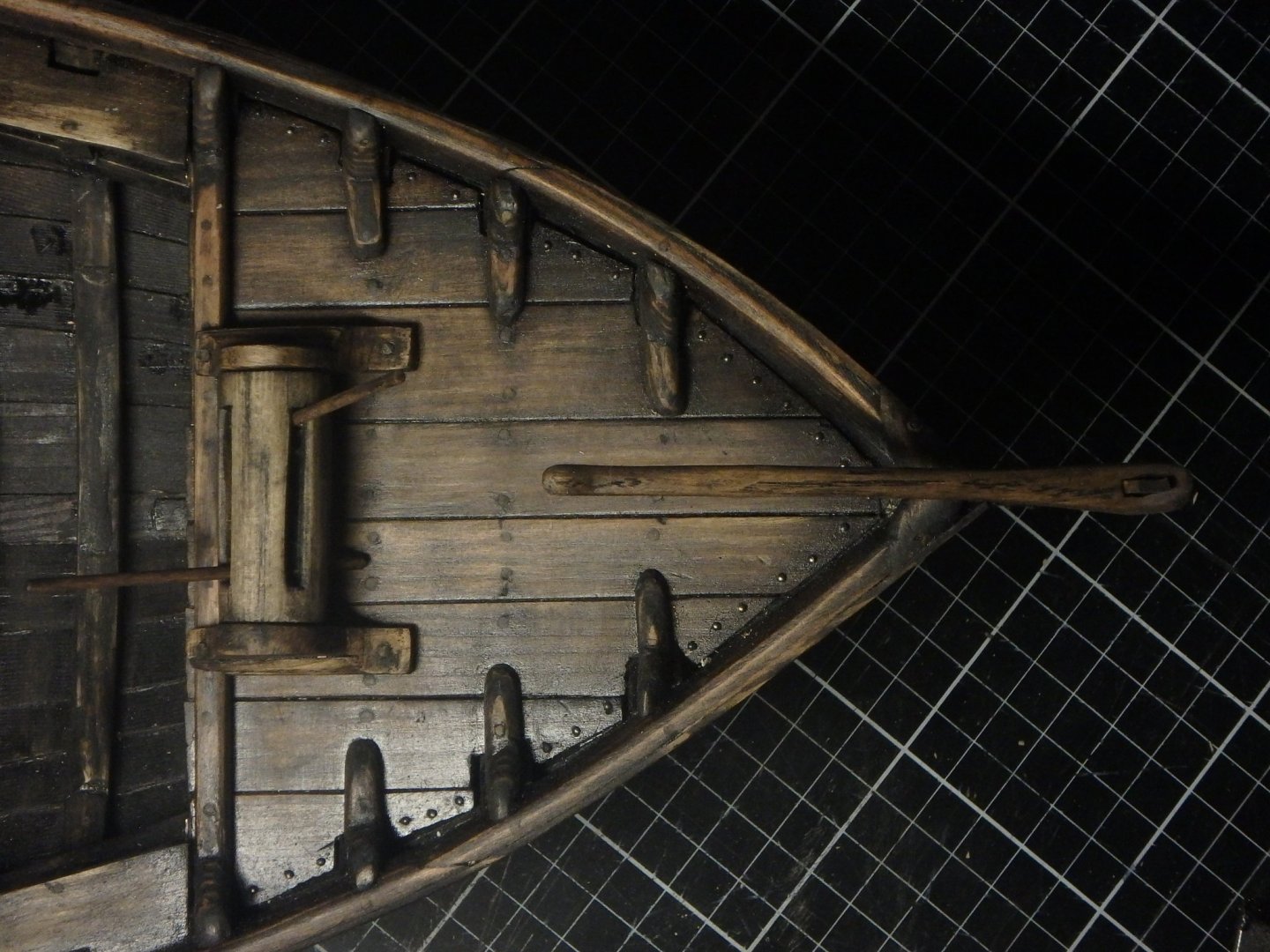
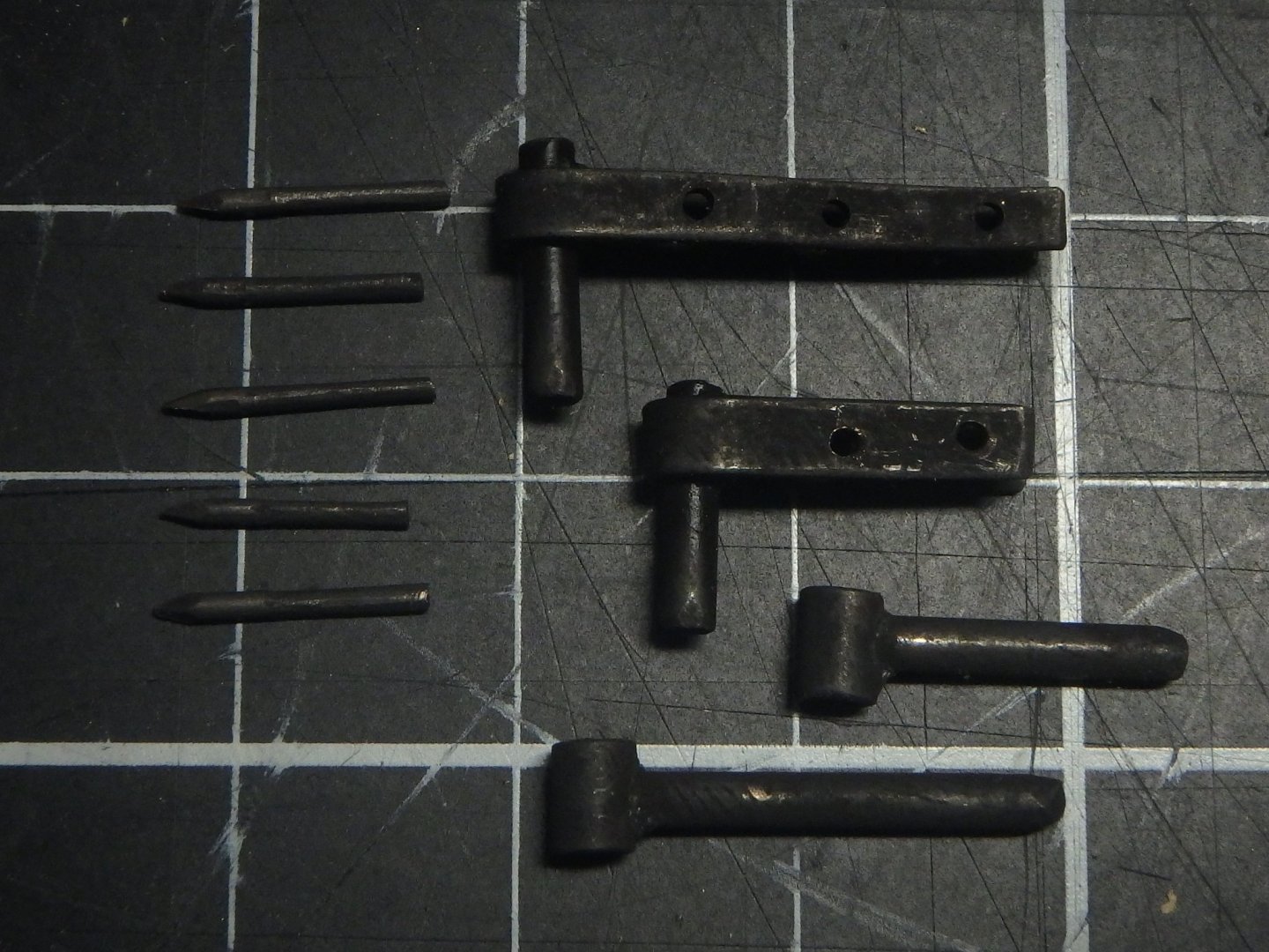
I feel as if treading water in the build as it goes so slowly. The main reason I think is all the work with finishing the hull, it will hopefully soon be finished and I'll talk more about the trials and tribulations then. Please ignore how all the nails are highlighted... But the rudder and windlass is done! The tiller and the sides of the windlass are carved in oak and it was a nice change from the fir, I definitely now see why one should build in harder woods. The drum of the windlass is based on the Kalmar 1 find. I have always struggled with soldering but after reading up a bit I now understand the use of flux and now it went much better.

-
This is just an amazing build! It must feel great, and strange, to have it finished now. I'm reading through the whole log now and learns a lot, eg. the pump in the front is not a waterpump as I thought but a flame thrower!
-
Nice to see how the build comes along! And nice picture of the forestay with the hearts! That's an idea I think I'll steal to my ship.
-
Amazing build! It's very interesting to follow and thank you for posting the GIFs, they are very helpful!
-
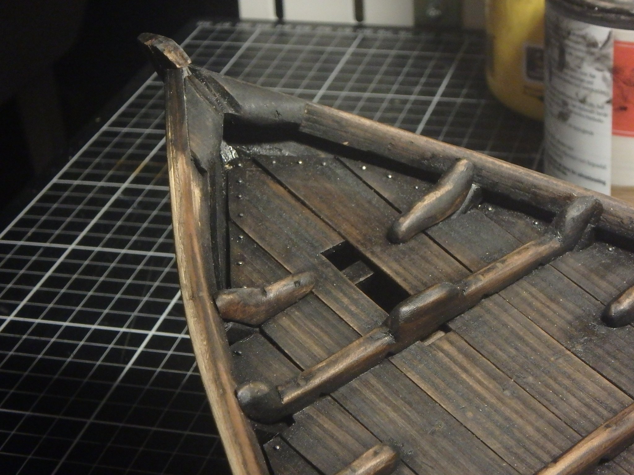
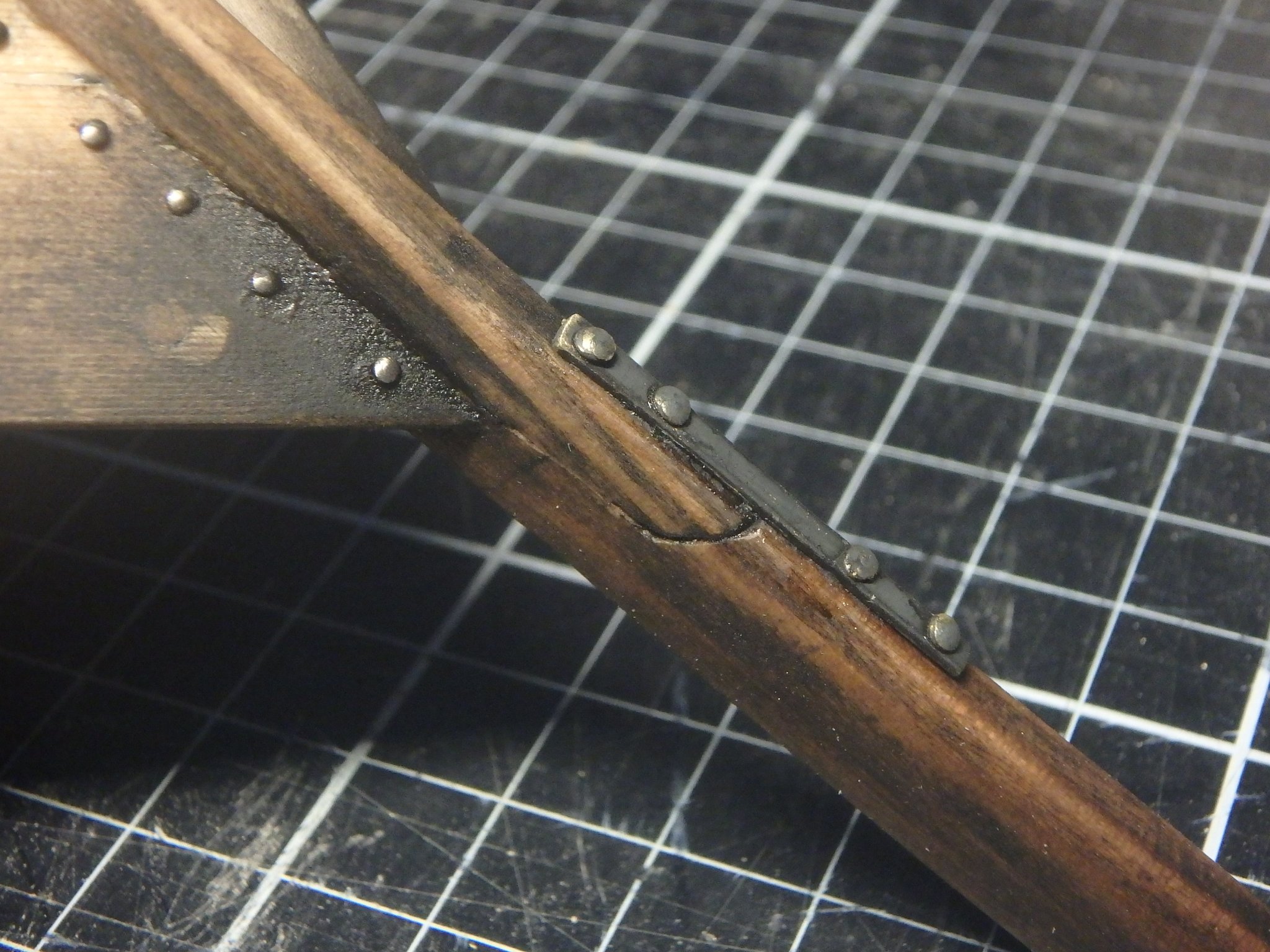
The foredeck looked like this to recieve a seperate bowsprit But instead I extended the stempost and remade bits of the deck. We can say that part of that plank on the deck was damaged and a new insert was nailed there. I can not imagine a worse place on the ship for a scarf joint as the forces here are quite severe. So I nailed an iron plate (made of brass) as reinforcement to addition to two treenails. The funny thing is that the stempost used to be almost of this lenght. My original plan was to have an integrated bowsprit like this, but I changed my mind and sawed it off. And now changed it back again. Let us say that the ship ran into something and broke off the stempost/bowsprit if somebody asks about the joint.


-
Nice to see a build of a swedish boat! It will be most interesting to see how the longboat developed and what solutions you come up with for the rigging.
- 179 replies
-
- 2
-
-
- longship
- Helga Holm
- (and 1 more)
-
I have slept on this and practically all cogs have bowsprits. And so must mine. But I think I got a solution that I like - I'll extend the stempost and use that as a short bowsprit. That will both fit with finds and my design intentions. And in other news: I have got a tattoo of my ship! It's not a tattoo depicting the ship but a tattoo that the ship gave me. A splinter got pretty deep in a finger a week ago and left a fair amount of the dark paint when removed and I guess the dot will be there for a couple of years.
-
Steven, thank you for your thoughts on this! Yeah, I see this ship as provincial and they wouldn't bother with flags and stuff. Thinking more about it I think I will remove the bowsprit altogether, it will require rebuilding the foredeck, but I want to understand all the features I have on the ship and at this point I simply don't understand why it would have a bowsprit. I also want the ship to have a sturdy feeling to it and this pointy thing in front doesn't fit in.
-
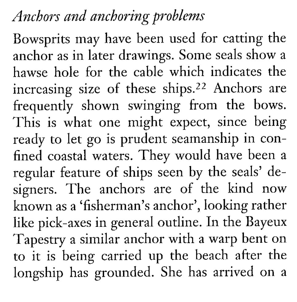
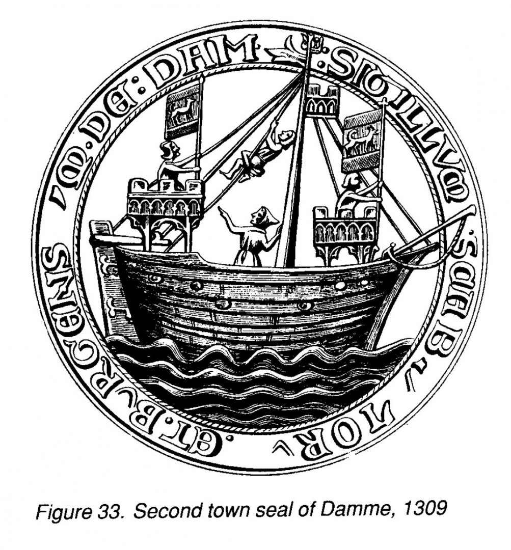
Thank you Steven and Binho! Yes Steven, I got really good help in the other thread. This is a really good forum for advice, and I need some more later in this post if you have the time. I got a simple solution for the problem with the forward bulkhead blocking movement of the boom - the three planks of the bulkhead are each individually removable. I once again used the bowsprit as a stand in for the boom. And whilst on the topic of the bowsprit I've been thinking more about why I even have one. I thought earlier that I would have bowlines running to it, but they have now been removed from the plans and I now only have the forestay on the bowsprit - which hardly justify it's existence. What about having an anchor on it? The book Cogs, Caravels and Galleons has this to say about this: This image if from another source Should the anchor line go through a block in the end of the bowsprit? That feels a bit weak, what about a short chain in the end of the bowsprit with a ring that the line goes through? What do you, dear reader, think? Or could it be that it was warships that had grappling hooks on the bowsprit?
-
Problems with a medieval bipod mast
Brinkman replied to Brinkman's topic in Masting, rigging and sails
Good thougths regarding timing, I'm stuck in the modern concept of just in time delivery and have a hard time imagining a ship waiting for days for favorable winds, but yeah, you are right about it. There have been three replicas built of the bremen cog and they seem to also have lifts and braces, but no bowlines. They are also bigger then my cog and I don't think the lifts will be necessary but I think it could have been good to have braces as most square sailed ships my size seem to have them. I think I'll skip the bowlines. I partly planned to have them as the bowsprit otherwise would just have the forestay, but I guess that's ok. -
Problems with a medieval bipod mast
Brinkman replied to Brinkman's topic in Masting, rigging and sails
Thank you Roger for the input and as I'm new to sailing I want to make sure that I understand you correctly; you mean that the only running rigging should be halyard and sheets? I thought I also would add braces and bowlines. Thank you Jan, you are of course correct that the ship couldn't be drawn on the Zuiderzee, but not even along the rivers as they also must have had very soft edges. I wonder how they did it as it sounds hard to punt a 20 ton ship. -
Incredible work! I love the interior details, thank you for sharing.
-
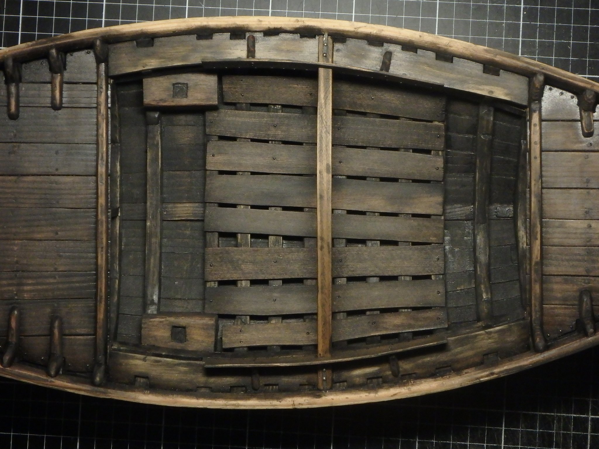
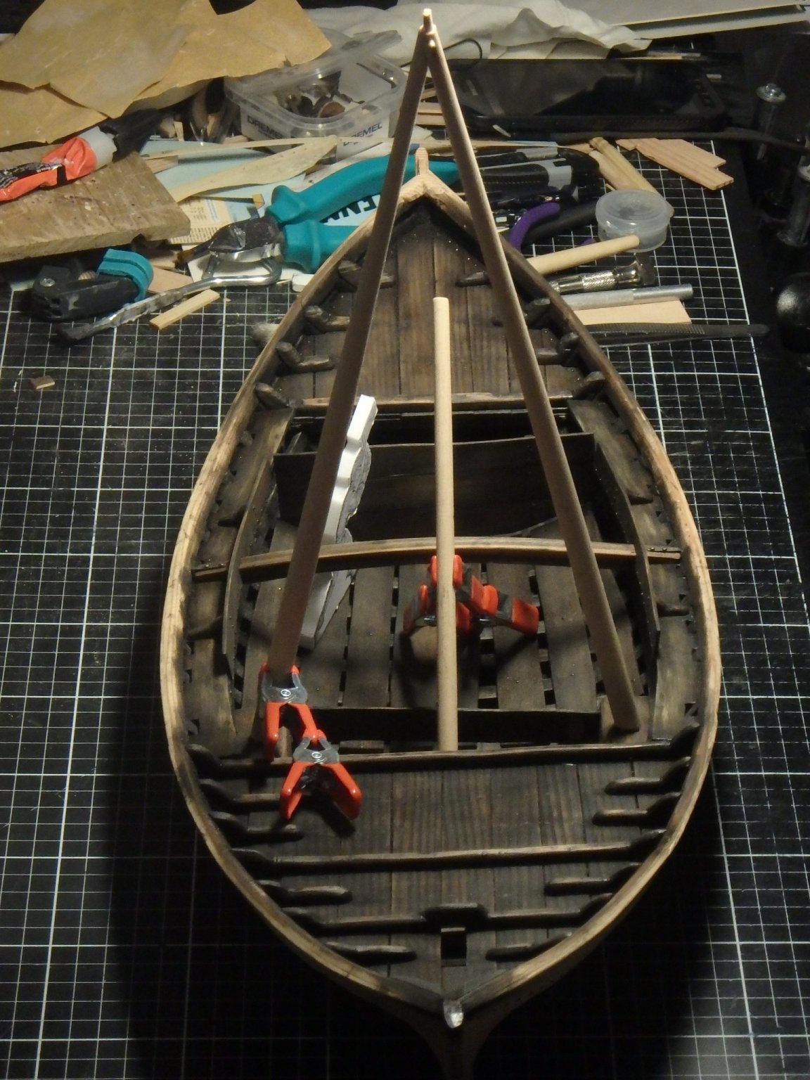
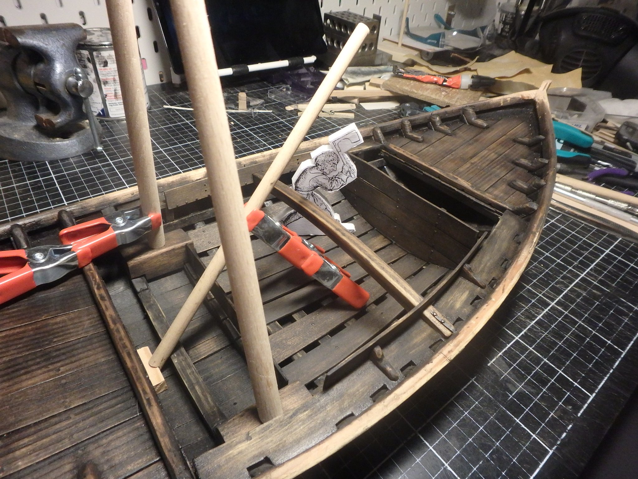
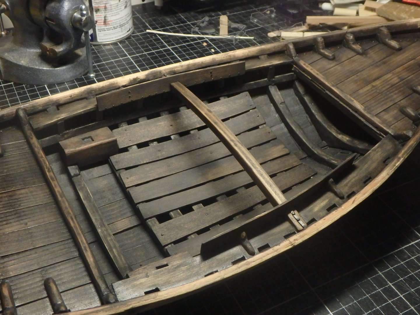
The gangways lets the crew cross the hold without having to crawl over the cargo and a sturdy beam spans the hold to keep the hull from bulging out. Rosebolts keeps it in place. The twin mast steps for the bipod mast are in place, and they act as steps to get up on the gangways. The hold has a nailed down ceiling to keep the cargo out of the bilge, but the planks in the middle are loose for cleaning out dirt. The planks are roughly sawn with natural edges. I've started with the mast and will have a boom for lifting cargo, here shown with the bowsprit in its place. Calculations in the thesis about the wreck calculates that the ship reaches it's cargo limit when filling up the hold with bricks, so I imagine the ship was made for smaller amounts of high density cargo rather than large amounts of light. And then a lifting boom would make sense and the bipod mast could be there as support. Bulkheads are of course needed to keep the cargo in place and I did sides for the gangways for this purpose and a simple bulkhead aft of the hold. But it's hard to fit a bulkhead in front as the boom intervenes with anything higher than 40cm ( 1 1/3'). I must come up with a better solution here.


-
Problems with a medieval bipod mast
Brinkman replied to Brinkman's topic in Masting, rigging and sails
Thank you Roger and Bolin, it sounds as if I don't have to worry about a parrel and maybe just add a trozza if I see the need. Thank you! I havn't seen any signs of oars in these wrecks and imagine the ships running with a minimal crew and probably waiting for favorable winds, or maybe finding a farmer with oxen to drag them? -
Problems with a medieval bipod mast
Brinkman replied to Brinkman's topic in Masting, rigging and sails
Bolin, thank you so much for the added details! Interesting idea to switch which leg the parrel is on! Now I have some more ideas to play with when planning this, thank you both. -
Problems with a medieval bipod mast
Brinkman replied to Brinkman's topic in Masting, rigging and sails
Steven, I think lowering the whole mast egyptian style would be too much work for the crew but the idea of using a trozza sounds like a simple solution that probably would work, thanks! Bolin, I'm sorry but I'm too new to this whole sailing business to follow. What is a down haul in this context? And what do you mean by lowering the sail while tacking? -
Problems with a medieval bipod mast
Brinkman replied to Brinkman's topic in Masting, rigging and sails
One possible reason for not having a single mast step could be the weak bottom. The keelplank is very thin and perhaps it buckled when they tried using a single step? I like your idea of a crane, but I think it would have been placed much further forward to reach in front of the ship. But a possible reason could be that the bipod mast was holding a lifting boom, something like this (I'm just using the yard here for show).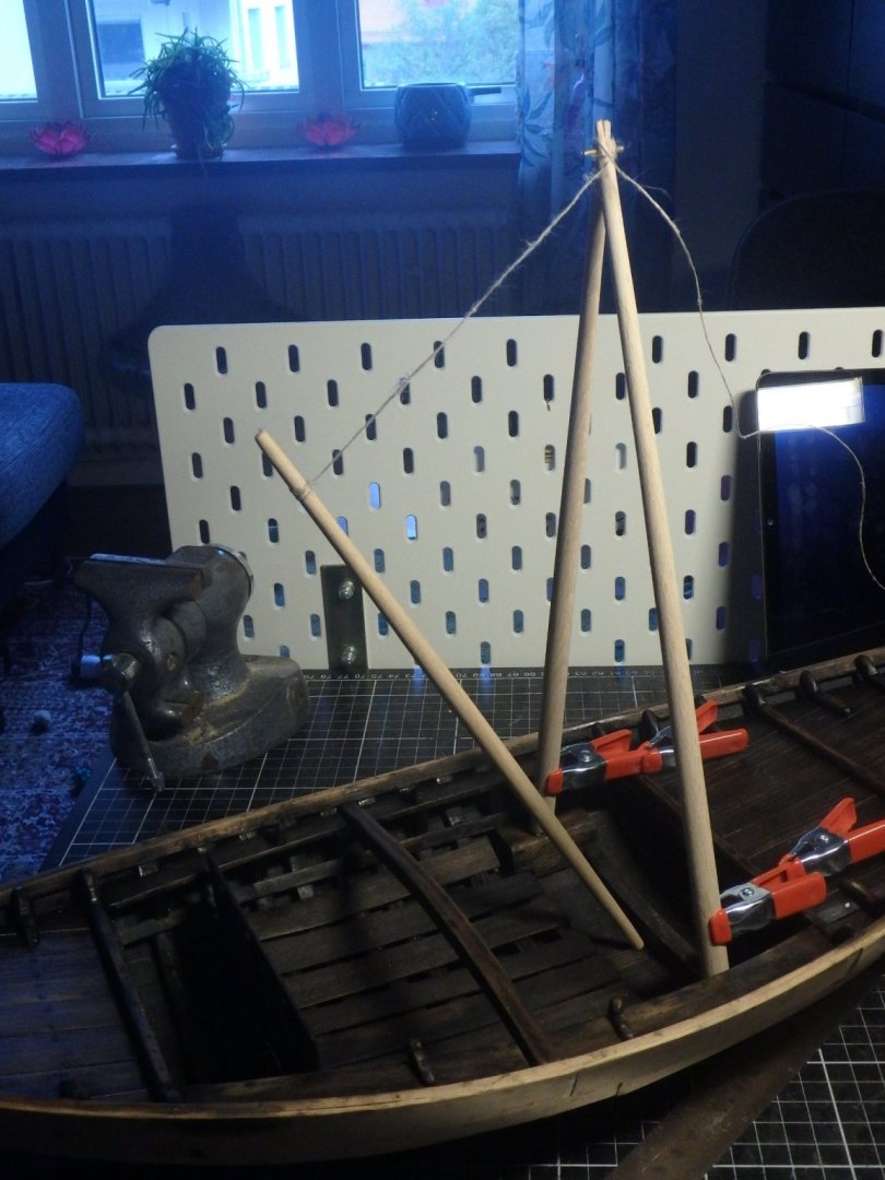
-
The work with furnishing the hold continuous, but I'm also looking into the mast and just can't figure out how to fasten the yard to it. I created a thread for it and would be grateful if anybody has any ideas of how to solve it.
-
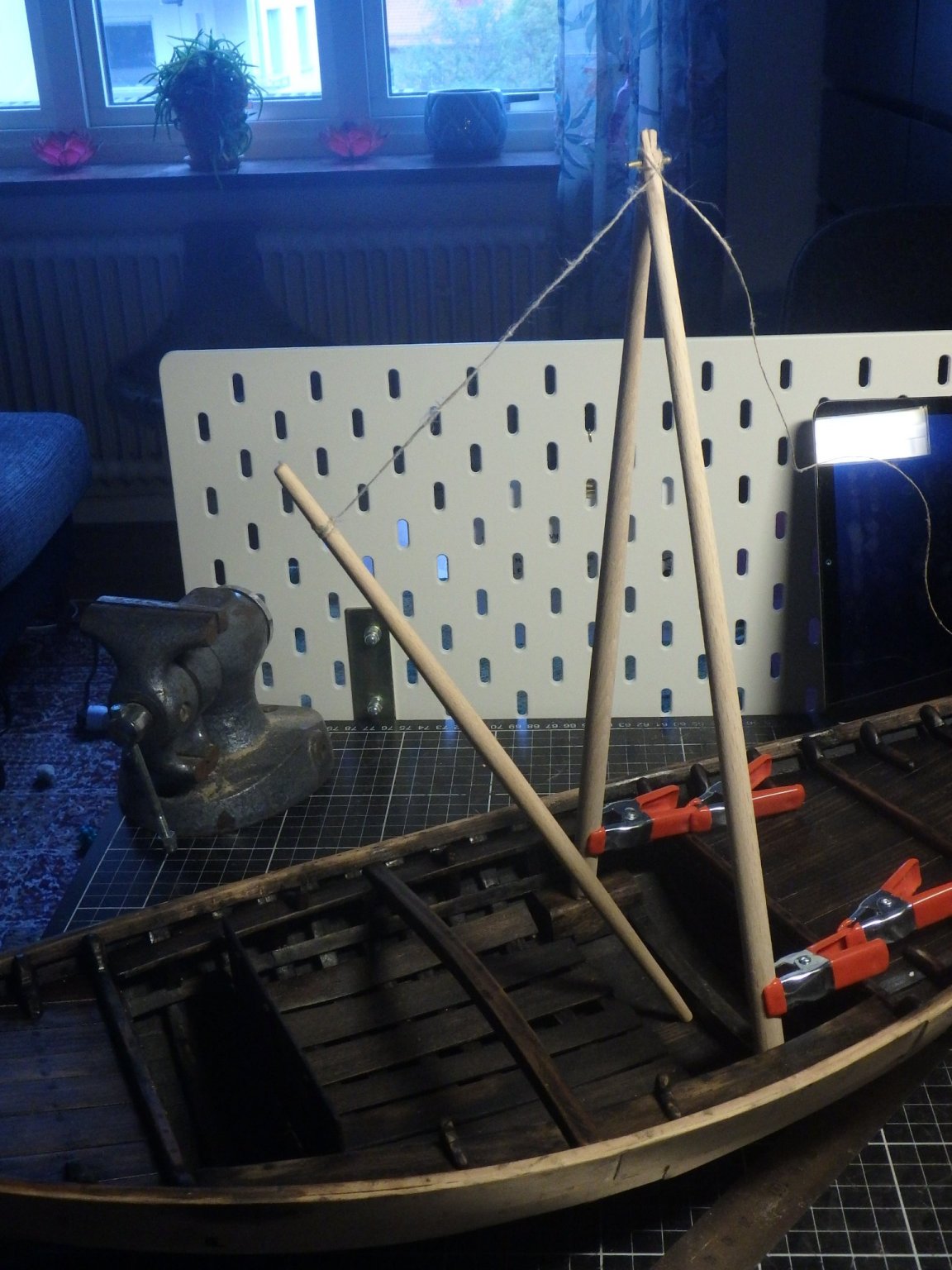
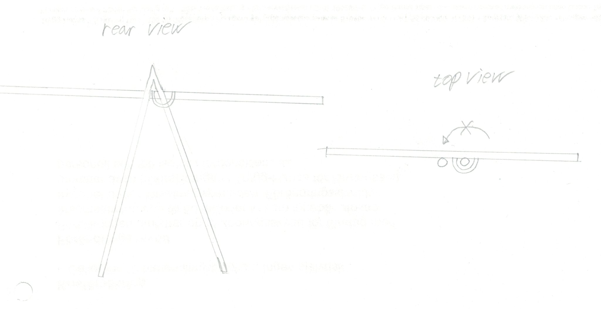
I'm scratchbuilding a small cog based on a thesis about a wreck of a medieval cog. The ship is just 11 meters (36') and the author hypotheses that it maybe had a bipod mast. This is based on the two mast steps in the wreck and a medieval image that maybe shows this kind of mast. Bipod masts are almost unheard of except for egyptian ships and modern catamarans and I find it hard to fasten the yard. It will have a square sail. If it has a parrel on one leg than the yard can't really swing to the other side. But is it possible to skip the parrel and just pull the halyard tight? This doesn't feel particularly secure. The bipod mast didn't catch on, if it ever existed in the medieval period at all, and this could be one of the reasons. But imaging a shipwright that thinks that he got the best idea ever - a bipod mast! How would he solve this? I have a thread of the build over at