


AnobiumPunctatum
-
Posts
1,233 -
Joined
-
Last visited
Reputation Activity
-
 AnobiumPunctatum reacted to Chuck in Sloop Speedwell 1752 by Chuck - Ketch Rigged Sloop - POF - prototype build
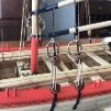
I finished the first layer for the wales. Basically I added two more strakes below the first that was added. I show this image because its the first that gives you a good indication of what the hull will eventually look like. This is as low as the planking will reach on the hull. Everything you see below the wales is left unplanked and these frames will remain visible. I do love a fully planked hull though. Its my preference actually. But like everyone else, I would be crazy to cover up all of that hard work with the frames.
I will add two more strakes now above the wales. They are also 7/32" wide. Then it will be time to remove all of the top jigs. Yippeee!!!
Chuck
-
AnobiumPunctatum reacted to Chuck in Sloop Speedwell 1752 by Chuck - Ketch Rigged Sloop - POF - prototype build
The first thing that needs to be done in preparation for planking is to paint the port openings. It is much easier to do so now and those familiar with all of my Syren projects will recognize this step. I am using the same Crimson Acrylic red for this model that I use for all of them.
One note however, rather than just start painting, this model has many laser cut sweep ports. The insides of the sweep ports have laser char on them. You really cant successfully just paint over that. The red wont cover it and will appear too dark. You dont want to sand it off. That would be bad. It would change the precision shape of those port openings.
Instead of sanding, I painted the insides of the sweep ports with a very light tan first. This will cover the char without compromising the shape of the sweep ports. I mixed Titanium White with some brown and yellow Ochre. Once that paint dried I switched to the Crimson.
One additional note....The quarter badge opening and window area was painted tan and will NOT be painted red. This will be left tan as the great cabin will remain unpainted.
Once the painting was complete I taped the two templates into position on both sides of the model.
This is a VERY important step. Just like when using a batten, you must view the hull at all angles. Ensure that the template is even on both sides of the hull. The bottom edge of the templates represent the top edge of the wales. You will be carefully tracing along the bottom edge of each template to mark the location for the first planking strake to be placed on the hull.
Make sure the run is good and at equal height at the bow and stern both port and starboard.
I forgot to mention that you should cut out all of the sweep ports and gunports from the template before taping it on the hull. In addition, cut out the fixed blocks on the templates too. You will be tracing and marking the exact locations for the fixed blocks and the sweep port covers as well as the bottom edge of the templates.
We will be adding the sweep port covers to the hull soon so we can plank around them. The same is true for the fixed block shells.
Use a hard lead pencil so it keeps a sharp point longer. Yes the lead will leave a lighter line but it will be more precise. Use a 4H or even a 6H pencil for marking the hull.
When you are done tracing these elements and the bottom edge of the templates, remove the them carefully. We will be using them again many times. Cut away any tape that hangs over the edges of the template. Dont try and remove it...the template will tear. Then store the templates safely for later use.
Here is what the hull looks like after removing the templates.
You can hopefully see my reference line that shows the top edge of the wales. But its hard to see the sweep port lines in the photo. Thats OK. Just know that they are there. You can see the locations of the fixed blocks.
We will be adding the first strake which represents the first layer for the top of the wales. This is probably the most crucial of planking steps. So take you time with it. If the run and fit for this first plank is wrong then all of your planking will be wrong. It will be hard to recover from that.
The strips are 7/32" x 3/64" Yellow cedar. I have a whole bunch of them ready to go. All have been matched for color. All three strakes for the wales are 7/32" wide. Try really hard to align the top of the strip with your reference line on the hull. Make sure you match the placement port and starboard.
I wont rehash how to plank and how to bend the strips. I have done that so many times. Just refer to the tutorials and many logs on this site. Or download the respective chapters for the Cheerful or the Winchelsea. I am using a travel iron and bending and twisting as usual. The first strake or the upper wales have been completed. At least the first layer. I prefer to use two layers. You could however just use a thicker strip and complete the upper and lower strakes in one layer instead. Its up to you. But I personally prefer two layers because I think I can do a much better and cleaner job with the painting and placement.
With this upper wale in place...now its time to add two more strakes of the same width and thickness below this one. It sounds easy enough, but remember to get a good tight fit against the strakes already on the hull. I am also using a #2 pencil to shade one edge of each strake to simulate the caulking. Although on the upper and lower wales its not important. Its only the first layer. I would however simulate the caulking on the middle layer of the wales because it is only one layer thick. I a referring to the butt joints only.
One last very important note: When gluing these three strakes for the wales onto the hull, make sure you glue the strips to each and every frame. Its the planking that will hold the hull together when we remove the top jigs. So the frames need to be really secure to the planking. Place a drop of glue (your choice of PVA or CA) to each and every frame as you proceed. When we complete two or three strakes above the wales later, thats when we will remove the top jigs and establish the sheer properly. So thats coming up soon. If the planks arent secured to the frames it might be a disaster in the making. But maybe not. I am just a nervous Nelly.
-
AnobiumPunctatum reacted to Chuck in Sloop Speedwell 1752 by Chuck - Ketch Rigged Sloop - POF - prototype build
The Speedwell castings arrived. Just like the Winnie these are cast in a very light Tan. Almost white but not. This is a big help for the finishing. They were treated just like those on the Winnie. See the unfinished quarter badge on the can of gel stain?
I used Old Masters gel stain. The color is Fruitwood. This is the best color for our purposes in my opinion. Just brush it on and let sit for a few minutes. The longer you leave it on the deeper and darker your color will be. Dont leave it on too long...you can always add another coat after it dries.
Brush it off before it dries however with a soft clean brush. Almost buff it. The more you brush the more you will remove. This evens it all out while leaving darker bits in the deeper areas. But not overly so.
The one drawback with this method is the parts tend to get shiny. But a quick spray with some dull coat after it dries does the trick. The color matches quite well as you can see. This preserves all the detail as well because unlike paint, this does not build up and obscure the small details.
-
AnobiumPunctatum reacted to uss frolick in Sloop Speedwell 1752 by Chuck - Ketch Rigged Sloop - POF - prototype build
The model is indeed of the Endymion 44, of 1785, a later sister to the Serapis/Roebuck, etc, owned by the Science Museum, in London. The central window arch in the stern gallery is certainly unique. She later wrecked in the Bahamas, striking was to become known as Endymion Rock. The later Endymion 40, of 1797, was built to the lines of the captured French La Pomone, and in addition to fighting the USS President in 1815, she was the fastest frigate in the RN.
-
AnobiumPunctatum reacted to giampieroricci in HMS PEGASUS by giampieroricci - Scale 1:36 - Swan-Class Sloop from plans by David Antscherl & Greg Herbert
a slight difficulty for these hinges:
everything is provisional still, I have to prepare the right-hand doors before fixing the bulkhead and beam
-
AnobiumPunctatum reacted to AON in HMS Bellerophon 1786 by AON – scale 1:64 – 74-gun 3rd Rate Man of War - Arrogant-Class
Had to get some yard work done. Cut the grass. Install a new 1000 litre tote box/ rain water collector for the garden. Move three yards of mulch.
My shop needs cleaning and the wife's new out door dory wooden flower pot is cut, steamed and bent and sitting on the bench for more than a week now waiting to be assembled so she can paint it.
But the sun was out... raining buckets today.
Got my crutches/oar lock pockets cut into the washstrakes using files and mini chisels.
Rudder installed with blackened paper gudgeons and pintles.
Tiller made and installed.
Just the sweeps/oars left to do. I've got all pertinent dimensions and am ready to move... but I better get the dory done first.
The tiller is a black jewellery wire dabbed in Weldbond PVA glue to create the balled end. When dry this was painted black with acrylic paint.
This was cut to length and glued to the rudder.
The rudder is mounted to the boat with blackened paper bands and jewellery wire pins.
The fastener heads on the bands are simulated with dabs of Weldbond PVA glue using a fine point straight pin.
The glue goes on white but dries crystal clear so it seems to be black as the paper under it is black.
-
AnobiumPunctatum reacted to Chuck in Sloop Speedwell 1752 by Chuck - Ketch Rigged Sloop - POF - prototype build
I will probably provide both. I like more of the blue field without them.
Here is a pdf if folks want to print one out and see what I am working on.
They are far from finished. I am still working on the colors and details...
sternfrieze.pdf
-
AnobiumPunctatum reacted to Chuck in Sloop Speedwell 1752 by Chuck - Ketch Rigged Sloop - POF - prototype build
Well I am starting to feel much better although I am not making any rope or blocks yet. Still very exhausted. So my inventory will have to wait. But I did spend a relaxing day yesterday working on Speedwell. Mostly out of boredom. I dont know how some folks can sit around all day doing nothing.
Anyway...this starts chapter 3.
The square tuck and counter planking.
Everyone knows a square tuck can be very very tricky to make so it looks good. Rather than fart around with individual elements I decided to take a shot at doing it the exact same way the model builder of the contemporary model did his square tuck. Unfortunately for him...he didnt have a laser cutter.
It took a really long time to get the shape absolutely correct so I liked how it fit. But once that was done, it took about 15 minutes to bevel the outside edge. There is a laser etched line for that so it was easy.
I also added the planking within that tricky framework as laser etched lines. This included treenails. But the treenails are for placement only. They are same size as we will treenail the hull planking. So you can drill them and use 15 pound black or dark brown fishing line for your treenails. OR...just use the laser etched ones as the final because it still looks pretty darn good.
Then glue them on the model making sure they are lined up port and starboard.
Keep in mind how a square tuck was used and its purpose. The plank ends would butt against this frame on the forward side. So it needs to stand proud of the frame already on the model when positioned. This should be by about 3/64" all the way down.
Then its time to plank the counter. The counter planks are laser cut just like on the Winchelsea model. They are pretty straight forward. Sand the sides flush when dont with the hull so planking the sides of the hull will be nice and neat.
With that done I wanted to take a stab at seeing what the colors of the model will eventually look like. The contemporary model is painted with solid areas. The counter being almost a dark blue gray...almost black. A dark blue stripe down the sides of the hull with a read stripe above that.
I wanted to see what a frieze might look like keeping the same color scheme rather than just paint solid areas like the Contemporary model.
So in my sick boredom state...I colorized the template and made a first go at a stern frieze and hull frieze. Just to see how they would look. They are just taped on. Now I realize this might look weird with not seeing the black wales present, but it actually does give you a good sense of what this color scheme might look like. Once the moldings and wales and stern carvings are added it might look very good. Imagine the insides of the ports red and the bulwarks as well....In fact I think I like this far better than just painting the hull with solid colors. What are your thoughts...Any comments?
-
AnobiumPunctatum reacted to garyshipwright in HMS Montague 1779 bygaryshipwright - 74-gun Alfred-class
Hi Tobias and thank you for the compliments. Yes I drafted the plans of her, the half breadth plan and then her frames from that. I also drafted the lay out of her deck lines from the shear plans. One does have to be very careful because after many years the plans have enlarge, grown and redrafting this parts, help's straighten this out. Makes her easier to build. I do thank you for your kind words.
-
 AnobiumPunctatum got a reaction from Chuck in Sloop Speedwell 1752 by Chuck - Ketch Rigged Sloop - POF - prototype build
Definitly not. But to learn from Chuck and some other producers can help to make it possible or much easier to build the ship you like to have.
-
 AnobiumPunctatum reacted to whitejamest in Sloop Speedwell 1752 by Chuck - Ketch Rigged Sloop - POF - prototype build
Rumors confirmed: Syren Ship Models to produce Millenium Falcon kit in Alaskan yellow cedar.
Future plans for boxwood Death Star in 3/32 scale uncertain.
-
 AnobiumPunctatum got a reaction from mtaylor in Sloop Speedwell 1752 by Chuck - Ketch Rigged Sloop - POF - prototype build
Definitly not. But to learn from Chuck and some other producers can help to make it possible or much easier to build the ship you like to have.
-
AnobiumPunctatum reacted to Chuck in Sloop Speedwell 1752 by Chuck - Ketch Rigged Sloop - POF - prototype build
Laser cut parts...CNC parts...3D printed parts
They can only get you so far. This is certainly not like a lego set of the Millennium Falcon....LOL
But having said this, the goal is to have it NOT look like a kit when you are done. I strive to make my projects look as close to a scratch built model and contemporary model as possible. Otherwise I wouldnt make them. But I admit they are more advanced and more deceptively finicky than other MFGs.
But yes...it looks real easy in the pictures. Wait till you see the miniature model take shape.
Chuck
-
AnobiumPunctatum reacted to garyshipwright in HMS Montague 1779 bygaryshipwright - 74-gun Alfred-class
Hello every one. It's been awhile since I posted any thing on Montague/Alfred but wanted to get the the planking done on the Winchelsea and after 6 month's or so of building the bulkhead's and planking her in boxwood I finally went back to work on Montague/Alfred. Been slowly working on adding more beams to the upper deck. I added a few photo's of the Winchelasea and do hope you enjoy the photo's. Sorry about the delay on getting back to her. Gary
-
 AnobiumPunctatum got a reaction from Ryland Craze in Sloop Speedwell 1752 by Chuck - Ketch Rigged Sloop - POF - prototype build
Definitly not. But to learn from Chuck and some other producers can help to make it possible or much easier to build the ship you like to have.
-
 AnobiumPunctatum got a reaction from James G in Sloop Speedwell 1752 by Chuck - Ketch Rigged Sloop - POF - prototype build
Definitly not. But to learn from Chuck and some other producers can help to make it possible or much easier to build the ship you like to have.
-
AnobiumPunctatum reacted to giampieroricci in Sloop Speedwell 1752 by Chuck - Ketch Rigged Sloop - POF - prototype build
Chuck, what you are doing for this model of yours is something amazing, with unmatched precision and detail!
This proves that when there is synergy between man and machine you can get the best out of both! I follow you with great interest!
-
 AnobiumPunctatum got a reaction from Razer in Sloop Speedwell 1752 by Chuck - Ketch Rigged Sloop - POF - prototype build
Congratulations for reaching this very impressive milestone.
-
AnobiumPunctatum reacted to Chuck in Sloop Speedwell 1752 by Chuck - Ketch Rigged Sloop - POF - prototype build
Chapter two has been completed...
I managed to complete the stern framing. Its much easier than a larger frigate like the Winnie. Its just a matter of going slow and taking careful measurements. I have also added some features which will make alignment pretty tough to do wrong.
Here are the steps...sorry for the long post but these are my notes for the instructions while I remember them.
To begin...take the two center stern frames. Sand the laser char from the forward side and the the sides. No reason to do the aft side.
There are slots on the top of the wing transom where the bottom of these frames will be positioned. The forward edge of the stern frames should be flush with the forward edge of the wing transom. You will notice how the aft edge of the stern frames hang over the aft edge of the wing transom. This is by design.
The top of each stern frame will rest in the notches laser cut into the jig on the top of the hull. Just rest them in the notches but dont glue them here. The stern frames are only glued onto the wing transom. A rubber band holds the top of the two center stern frames together and in the notches of the jig. Put one or even both of the keys back into the jig (the keys for centering the stern post earlier) to help pull the stern frames forward so they sit firmly in the notches of the jig.
Then slide the laser cut spacer (3/64" thick) between the two center stern frames. This may cause the stern frames to spread apart a little. That is fine. The filler are a perfect fit. Dont sand anything off the filler. Have it sit flush with the aft edge of the stern frames. The bottom edge should also sit flush to the bottom of the stern frames as shown. Note the laser etched reference line for the stern window sill along the bottom. This will be important really soon.
Then add the two remaining fillers on either side. You may have to tape these in position. If you didnt fair the inboard side of your quarter pieces enough they may be too tight. Dont sand the filler pieces to fit. Sand the inboard side of those quarter pieces on the hull so they fit. Use apencil to precisely mark where the stern light (window) sills will be placed. Just draw a reference line on the stern frames and quarter pieces.
We will now add the stern window sills between the stern frames. These are laser cut for you. Clean the laser char from the top and bottom of these pieces. They have been laser cut slightly longer than need.
There are paper templates on the plans for these three pieces. They are used to shape the gentle curve of the transom. Glue these to the top of each piece. Sand them to shape. The one on the left has been sanded already....remove the template and get ready to install them.
Leave the center filler between the two stern frames for now. We will add the outer sills first with these in position. Install these using your pencil reference lines for their proper placement. Sand the sides to get them to fit snug as they are laser cut slightly longer. Make sure you dont spread the open space apart because your sills are too long. That would be bad. Make sure they fit snug but with no movement in the frames or quarter pieces. See below.
Then remove the center filler and do the same with the center windowsill. Note how I removed the aft jig on the top of the hull at this point and set it aside. This will be important in the next step. I also sanded the the outboard edge of the sills to fair them into the general shape needed. You want the transom to sit flush against the stern frames in the next step.
OK were going to add the laser cut transom next. You may want to do a test run with just tape initially. It is 3/64" thick. One side of the transom has laser etched reference lines on it. This is the INBOARD side. Those lines are to help you position it correctly. In fact, it is more important that use look at the inboard side while you test fit this. Maybe with some tape first.
This is how it looks outboard...
But inboard is where the magic happens. Its how you will position it properly. If you look really closely...at the back edge of the sills you will seethe laser etched reference line on the transom. That line is used to establish the height. If you placed your sills properly then you can align the transom so this reference line follows the top edge of the sills. This will leave a nice lip above it for inserting the stern windows later. Ihope that makes sense as I explained it.
There are also etched lines for the two center stern frames. They may be harder to see above but they are there. This will help you position the transom port to starboard.
So after this test fit you know what you need to do to get this positioned correctly. Its time to glue it on. BUT
Dont just add some glue to the aft side of every stern frame and quarter piece and the sills and go for it. That would certainly be a huge mistake. There is no way you can get this positioned correctly in one shot before the glue sets.
So...do it in stages.
Step one....Only apply glue to the aft side of the transom below the reference line for the sills. You should only glue the bottom of the transom in place first. Make sure the etched line is flush with the top of the sills. Make sure the center stern frames are "centered" between the reference for them. There is no glue on these so just use it to center to the transom port and starboard. At least down low where the sills are. Maybe your alignment is perfect for these toward the top of the transom and that is just fine right now. The cedar is soft and the frames are flexible as you are probably aware by now. Let that glue set firmly.
Step 2....Glue the sides of the transom to the quarter pieces. NOT the center frames yet. You can easily get a toothpick with some glue on it between the transom and the quarter pieces. Glue one side at a time. You only need glue on about 1/4" down the aft side of the quarter pieces.
With the sides of the transom secured...
Step 3...glue the center stern frames. Apply some glue on the aft edge of the stern frames....between the frames and transom. No need to apply glue all the way down to the sills. Just about a quarter inch down the stern frames is fine. Flex the stern frames so they fall right between the laser etched lines on the transom for them. Hold or clamp until the glue sets. Repeat for the remaining center stern frame.
This is how I managed to position it so perfectly. Dont be impatient and try to glue it on in one shot...it wont end well.
Now as long as your sills were positioned properly your transom will be as well.
One last thing in this chapter....two small "triangular pieces" laser cut need to be added. You can see it below. They sit on top of the quarter piece and against the transom to complete the run of the qdeck bulwarks. You do have to bevel the aft edge so they sit flush against the transom. They also sit flush with the outboard side of the hull. You can sand them flush with the outboard side when you are done. Also sand the top edge smooth so you get a nice run into the quarter piece.
Note....you may have noticed that I didnt sand the laser char of the transom edges. I am specifically talking about the inside edges of the window openings. I did this on purpose because I dont want to alter their shape. I will leave the char or paint it later. Better to have a good shaped window opening. That is more important. I also slipped that top jig back into position. You dont have to but it couldn't hurt to have more support at this stage. Just remember that if you turn the hull upside down from here on out, you will need to prop up the hull first. You dont want to damage the stern transom and stern framing.
Thats it for chapter two...the framing is completely done. Next up will be planking. I will start with the square tuck and counter. Then I will plank from the wales up.
-
 AnobiumPunctatum got a reaction from Obormotov in HMS Victory by guraus - scale 1:48 - plank on frame
Wonderful model and a really nice website
-
AnobiumPunctatum got a reaction from Obormotov in HMS Victory by guraus - scale 1:48 - plank on frame
There exist a second contemporary drawing of HMS Victory in the Danish Orlogbasen. Click on B18
-
AnobiumPunctatum got a reaction from mtaylor in Sloop Speedwell 1752 by Chuck - Ketch Rigged Sloop - POF - prototype build
Congratulations for reaching this very impressive milestone.
-
AnobiumPunctatum got a reaction from Chuck in Sloop Speedwell 1752 by Chuck - Ketch Rigged Sloop - POF - prototype build
Congratulations for reaching this very impressive milestone.
-
 AnobiumPunctatum got a reaction from Jack12477 in Sloop Speedwell 1752 by Chuck - Ketch Rigged Sloop - POF - prototype build
Congratulations for reaching this very impressive milestone.
-
AnobiumPunctatum reacted to Chuck in Sloop Speedwell 1752 by Chuck - Ketch Rigged Sloop - POF - prototype build
Yes it looks like that will happen. But keep in mind this is all new to me. So how viable it will be will be determined after I am assured I can do it. I will start a new build log for the mini speedwell once I get started. I have to start over and take pictures...I will also need to do some redrafting to incorporate what I learned from from experiments up to this point. I will also also admit that I dont own any of his books or any books on making miniature models. So I will just wing it and see how it turns out. I could start reading up on how everyone else does these extreme miniature models but I have decided to stay pure to my own unpolluted experiments. We shall see how it turns out.
Getting back to the full sized 3/8" scale version....another first for me as I have never built a POF model before....
Work continues on the framing.
The last two cant frames number 28 and 29 were added. These looked very challenging after reading Greg's account of building them. But once the proper shapes were drafted after about 5 attempts at tweaking them, they were surprising easily to bevel and add.
Here is a look at the two aft cant frames after shaping.
They are laser cut of course. With etched reference lines for the bevels required. The first ...number 28...was easy enough. Just a bevel along the top. This illustration should explain it better than I can describe in writing.
Then it was glued into place using the last remaining slot in the deadwood.
Aft cant frame 29 or as Greg and David describe it...a filler frame, was done just the same. But there are more bevels that were sanded into them with a sanding stick. I disc sander would do the trick in about 30 seconds. But as I mentioned, I am building this entirely by hand without power tools as I know many folks dont have those.
Its beveled to sit against the wing transom. But it is also beveled to sit against the deadwood. There is no slot created by those wedges for this one. The heel must be beveled in the traditional way. Laser etched lines show you exactly were to start the bevels. It doesnt take very long to do.
Lastly a bottom of the heel was sanded on a curve to match the bearding line. Then it was tested in position. Tweak it if you need to but mine fit rather well on the first go. I got lucky. Glue them in and fair the hull frames for one final last time. Here is a picture of those last two aft cant frames which you can see. This was taken after fairing. I also added the treenails for all of the frames to finish it up.
This completed all of the hull framing except for the upper port sills. So that was next.
These are also laser cut and rather simple to glue into position. I also laser cut a spacer that is the correct height. You can make your own that stretches all the way from port to starboard but this small length worked just as well. The spacer is laser cut in two layers. Just glue the layers together so you have a nice wide spacer. Rest it on the lower sill and position the upper. Its really very easy.
Do this for the six upper sills on each side. They were laser cut slightly longer than needed. Just sand it to fit nice and tight and glue them in. Then fair it into the hull.
This actually finishes up all the hull frames. All done and it took 5 1/2 months from design to completion at this point.
I only have the stern framing left to finish up chapter two. Then its on to planking. Here are some pictures. I am actually quite pleased since I had never built a POF model before. It was like diving right in the deep end. But surprisingly it all worked out according to plan. Withought any major challenges or redesigns.
I have posted an image of the framing plan right beneath the last photo so you can see how it all followed the plan as developed quite well. Who would have thought!!
And one last drawing......showing the difference in scales between the 3/8" and 3/32" scale Speedwell models.