


AnobiumPunctatum
-
Posts
1,232 -
Joined
-
Last visited
Reputation Activity
-

 AnobiumPunctatum got a reaction from FrankWouts in Sloop Speedwell 1752 by Chuck - Ketch Rigged Sloop - POF - prototype build
It is looking really nice. One question: I miss the different knees, especially where the guns are situated. David has shown them in his drawings. Why do you have omitted them?
-
AnobiumPunctatum got a reaction from FrankWouts in Sloop Speedwell 1752 by Chuck - Ketch Rigged Sloop - POF - prototype build
Thanks for the information. I fully understand your motivation not to make the knees
-
 AnobiumPunctatum got a reaction from Stuntflyer in Sloop Speedwell 1752 by Chuck - Ketch Rigged Sloop - POF - prototype build
Thanks for the information. I fully understand your motivation not to make the knees
-
 AnobiumPunctatum got a reaction from mtaylor in Sloop Speedwell 1752 by Chuck - Ketch Rigged Sloop - POF - prototype build
Thanks for the information. I fully understand your motivation not to make the knees
-
-
AnobiumPunctatum reacted to Chuck in Sloop Speedwell 1752 by Chuck - Ketch Rigged Sloop - POF - prototype build
The knees wont be seen so they will be omitted. Its easy enough for folks to add should they want to. Thats a benefit of having Davids book while building the kit. But it will really complicate and make adding all of those ledges take forever. And all for something that will never be seen. I think most folks will be relieved not to make them.
the contemporary model doesnt have them either. My guess is for the very same reason.
It also reduces the cost and time to manufacture the kit quite a bit. I did add them on the fcastle however because the ends of the knees will be slightly visible in the open area left unplanked. So once the gun deck is planked…the casual viewer will actually assume you did add all of those knees for the entire model. LOL
I will take a picture with the planking templates in position. You will see what I am talking about pretty clearly. The same is true of all the ledges down the center line. They will not be seen either. The contemporary model also omits these..whats the point really.
-
AnobiumPunctatum reacted to Chuck in Sloop Speedwell 1752 by Chuck - Ketch Rigged Sloop - POF - prototype build
I have reached another small milestone. All of the below deck fittings and cabins are completed. The gun deck is fully framed as well. Next up I will start planking the inboard bulwarks. That should make a huge difference.
I hope to see many of you this weekend at the New London show. It should be a very enjoyable weekend. I am looking forward to it.
Chuck
-
AnobiumPunctatum got a reaction from mtaylor in Beavers Prize 1777 by Mike Y - 1:48 - POF - Hahn style
I don't think so. In my opinion is the purpose of the drawing to show the differences between the standard frameing sheme (doulble frame followed by two single frames) and the sheme which was used for Kingfisher in the midship area. Interesting is also the triple frame midships.
-
AnobiumPunctatum got a reaction from mtaylor in Beavers Prize 1777 by Mike Y - 1:48 - POF - Hahn style
Ah, the midship frames from Kingfisher. For the first. Ships of the class the frameing design, which was introduced with Cygnet is not correct.
I am busy with another Swan Class Fly. For this ship the Cygnet design is with some small adjustments possible.
-
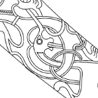
AnobiumPunctatum got a reaction from mtaylor in Redoing Oseberg
Hi Kris,
I am really happy that you continue with your reconstruction of ths beautyful viking ship. I will follow as in the last years with great interest.
-
 AnobiumPunctatum got a reaction from Mike Y in Beavers Prize 1777 by Mike Y - 1:48 - POF - Hahn style
Ah, the midship frames from Kingfisher. For the first. Ships of the class the frameing design, which was introduced with Cygnet is not correct.
I am busy with another Swan Class Fly. For this ship the Cygnet design is with some small adjustments possible.
-
AnobiumPunctatum reacted to Mr Pleasant in HMS Mercury 1779 by Mr Pleasant - 1:64 - based on Shipyard paper model
Hi All
Thanks for the likes.
Onto fitting the bulkheads
A quick jig was made to keep the spine vertical whilst the bulkheads were fitted. Bulkheads kept square using Lego and clamps
Once all bulkheads were fitted I added spacers to keep everything square, this is simply achieved by taking measurements of the gaps between the same bulkheads on either side of the spine and taking the average, two pieces of stock are then cut to that length and glued in place between the bulkheads
The 3mm ply spine is still flimsy at this point so bracing pieces are required. These are cut from the templates provided and 3mm ply is used. I cut the bracing pieces roughly 5mm less wide than the templates so that the edge of the bracing pieces were clear of the bulkhead edges..
Following shows a couple of the bracing pieces cut and installed clear of the bulkhead edges
Gaps in the bulkheads are plugged with some pine and sanded flush
The frame is now rock solid and straight
Thanks for dropping by
Mark
-
AnobiumPunctatum reacted to Curieux in Beavers Prize 1777 by Mike Y - 1:48 - POF - Hahn style
Either I start again the same model (without mistakes) or the HMS Beaver itself. In both cases, we have no framing plan (my guess, see photo).
HMS Beaver => french design but english built. Slade , the best english naval architect, was very keen on french design.
Date : 1770
-
 AnobiumPunctatum got a reaction from KrisWood in Redoing Oseberg
Hi Kris,
I am really happy that you continue with your reconstruction of ths beautyful viking ship. I will follow as in the last years with great interest.
-
 AnobiumPunctatum got a reaction from Rustyj in Sloop Speedwell 1752 by Rustyj - Syren Ship Model Company - 1:32 Scale - POF Sloop
This looks like a very promising start. I will follow with great interest.
-
AnobiumPunctatum got a reaction from Stuntflyer in Sloop Speedwell 1752 by Stuntflyer (Mike) - Ketch Rigged Sloop - POF
This is looking really really good.
-
AnobiumPunctatum reacted to Richard Braithwaite in Trireme Olympias by Richard Braithwaite
Putting it all back together:
Som images showing how the main units go back together after varnishing.
The main deck unit is placed inside the main hull unit and bolted together using a couple of brass screwdrives I made for the purpose (some of the bolts are quite fiddly to get at now all the seats are in place... The photo shows one of these screwdrivers accessing one of the difficult to get at bolts securing the base stringer.
I made a couple of "Link Seats" to connect the thranite seats at the aft end of the main deck unit to the ones fixed under the quarterdeck:
Then its a case of securing all 12 Canopy Units:
The assembly with all main units in place:
There are a number of other loose outfit fittings, like ladders to go in:
Complete assembly takes me about 1 hour at this stage. Hopefully I wont need to take it appart again for some time...
-
 AnobiumPunctatum reacted to Richard Braithwaite in Trireme Olympias by Richard Braithwaite
Current stage of varnishing complete. Please to say, none of my fears materialised:
1. The older work didnt look any different from the fresh stuff.
2. I managed to avoid blocking up the threads of all the captive nuts
3. The lightweight structure didnt distort.
Composite image of all the main components after sealing:
As an aside Ive got myself a new umbrella reflector kit to use for flash photography. It came with 2 umbrellas. These photos were its first outing, so still getting used to it... Im alreadyquite pleased with the "soft" white one which seems to give quite an even illumination (when I point it in the right direction!) with nice soft shadows...
-
AnobiumPunctatum reacted to Richard Braithwaite in Trireme Olympias by Richard Braithwaite
Main hull unit and main deck unit now coated with 5 coats of Polyurethane Matt (thinned 25% with White spirit) and Ive started the first coat on the deck canopy units, ladders and other misc bits and pieces. It took me four full days to sand where I could (600 grit) before I started and 7 full days to apply the 5 coats to the 2 main units with a brush (sanding between coats with 1500 grit paper). Very fiddly work, there are a lot of brackets, stanchions etc that are quite difficult to brush around - even with the model fully dissasembled. I could probably have done it quicker with an airbrush, but dont have much experience using them so went for the brush in the end. I am quite pleased with the finish I achieved. Even the older wood (worked over 10 years ago) has some up nicely and is indestinguishable from the fresh wood (e.d. tabernacles and stowage racks). I was really relieved to find I could fit the deck unit back inside the hull unit (after varnishing) and bolt it down with out any difficulty. I had managed to keep the threads of the captive nuts free of varnish and there was very little distortion of the two units from varnish absorbtion (the hull had opened up about 2mm - which I was easily able to pull back with the bolts to the beam shelf on the deck unit. Hopefully the canopy sections (even lighter built - and so even more sensitive to distortion) will behave as well.
Photo below shows how the wood like looks now...
-
AnobiumPunctatum reacted to Richard Braithwaite in Trireme Olympias by Richard Braithwaite
Forward tabernacle fitted complete with single steps to foredeck and braces...
-
AnobiumPunctatum reacted to Richard Braithwaite in Trireme Olympias by Richard Braithwaite
Simpler at the fore end where the forward most seats on the upper level sit on the removable section. Luckily the bolts that I put in this area cleared them (well almost...). At one point I wasn't planning to fit seats so these bolts were placed without thinking about them...
-
AnobiumPunctatum reacted to Rustyj in Sloop Speedwell 1752 by Rustyj - Syren Ship Model Company - 1:32 Scale - POF Sloop
Moving along I've finished the boxing joint and the first parts of the keel.
Next I'll add the false keel and the pieces on top of the keel for the rabbet strip.
-
AnobiumPunctatum reacted to Chuck in Sloop Speedwell 1752 by Chuck - Ketch Rigged Sloop - POF - prototype build
Thank You...
The cabins on the aft lower platform are completed. No detailed explanation since they are built exactly like the others. Each partition wall is built up with two layers glued together. Then they are detailed with hinges and door handles as required along with any upright timbers 1/8" x 1/8" strips. Their heights and widths are adjusted to fit under the deck beams etc. Finally they are assembled and glued into position.
Here is the tiny powder and filling rooms completed. These walls are slightly thicker than the other cabins as was normally the case. An extra laser cut sheet of parts shows how all the cabins are prepared for you. They are all numbered and shown on the plans. I built them in the order that they are numbered.
All of the cabins completed.
Next up is to complete the remaining deck beams carlings and ledges.
-
 AnobiumPunctatum got a reaction from Saburo in Naval Cutter Alert by AnobiumPuncatum - Scale 1/36 - POF
After the drawing works it was time to make sawdust.
First part is the keel, which is a little bit tricky. The keel has a light curvature and the joints are perpendicular to the base line.
I cut some small stripes with my cirular saw, make the joints and glue the parts together. Next I added the parts for the stem.
The picture shows the step on the building board. I use Tamiya Tape to avoid that the keel glues on the paper during the build.
The next pictures show the complete assembled backbone for the small vessel,
the stem with with the changed layout of the parts,
the keel and the rising wood,
and the stern post with the after deadwood.
The next steps are cutting the rabbet, the keelson and the building board. Then I can start with the frames.
-
AnobiumPunctatum got a reaction from Saburo in Naval Cutter Alert by AnobiumPuncatum - Scale 1/36 - POF
I was really suprised that I did not find a build log about the Naval Cutter Alert on MSW 2.0. I know that there exist some pictures of a model on the old MSW
The first source for building a model of this small vessel are Peter Goodwins book "The Naval Cutter Alert, 1777", published by PhoenixPublications Inc. 1991 and the two original drawing of her sister Rattlesnake (1776) which you will find on the homepage of the NMM.
There also exist two paintings of Joseph Marshall of the ship, which are exhibited in the Science Museum, London.
I found also an Sheer and Profile drawing of Alert which was published by the NRG.
The sheer and profile of the NRG and Goodwin differ from the original drawing. They show the maximum width of the ship not at frame 0. Perhaps my Engish is to bad, but I could not find any reason for this. So I decide to draw my own lines. which were based on Goodwin and the original drawing.
The drawing is not finished, because I decided only to draw what I need for my build.
Next step was the keel. Goodwin shows for the pass between keel and lower apron a solution which I could not find on any original cutter drawings.
For the after deadwood he does not offer any possible solution
I decide to follow the original drawing of Cheerful 1806 for the pass between keel and lower apron. The flat joint at the foremost keel part is shown on original drawings of this period (for example on HMS Triton). For the after deadwood I decided to use a bearing line. I am not sure if this is common for ships of this period.
The next picture shows my completed keel drawing:
Goodwin uses for his design the common frameing pattern of double and single frames. I am not sure that this design was used for the original ship. For the Swan class sloops only single frames were used. This you will also find on the drawing of Cheerful and other cutters. Also the wide of the frame parts are not clear. In his drawing he uses much smaller futtocks than he descibed in the text part of the book. In his "Construction and Fitting of Sailing Man of War" he gives a third solution.
What now? Alert is a practice model for me to get the experience to continue my HMS Fly build. Marshall shows on his paintings an simplified frameing design, so I decided to use this. Every frame is 8'' width followed by 8'' space. For the port side I like to show the clinker planking.
On my drawing the final design for the last frame and the hawse pieces is missing in the moment.
The drawings for every 31frames and 21cant frames are finished.
I am not sure in the moment if I will use the original practice with chocks or the simplified method of Harold Hahn for my build.
It will be very nice if you have further information about the cutters of this time. I found the Marmaduke Stalkartt on Google-books, but they didn't scan the plates. Perhaps one of the MSW user can help me to confirm my decisions.