


Gabek
-
Posts
309 -
Joined
-
Last visited
Reputation Activity
-

 Gabek reacted to Jim Lad in Shot Locker
Antony,
Sorry for the late reply, but here's a photo of the shot locker on the preserved frigate Trincomalee.
John
-
Gabek reacted to KJackson in Hello from Alberta Canada 🇨🇦
Welcome to MSW, Ken! It's fitting you're building the Bluenose 2, a beautiful Canadian ship. Will follow along with your build log.
I've just finished the Artesania Latina Bluenose 2 and have some good resources (books, practicum, plans) of her if you're interested? DM me if so and I'll share photos and links.
-
Gabek reacted to mtaylor in Hello from Alberta Canada 🇨🇦
Welcome to MSW, Ken. You've come to a good harbor with members willing to help. I suggest you open a build log for her as it'll help you meet others and also let folks follow along.
-
Gabek reacted to Jim Lad in Hello from Alberta Canada 🇨🇦
Hello ken, and a warm welcome to the forum from 'Down Under'.
John
-
 Gabek got a reaction from Dave_E in Hello from Alberta Canada 🇨🇦
Welcome aboard, Ken! You've come to the right place for advice…and the Bluenose is a popular model (of course!🇨🇦) so there will be lots of ideas and help available.
Clear skies and sharp tools!
- Gabe
-
 Gabek got a reaction from Peanut6 in Hello from Alberta Canada 🇨🇦
Welcome aboard, Ken! You've come to the right place for advice…and the Bluenose is a popular model (of course!🇨🇦) so there will be lots of ideas and help available.
Clear skies and sharp tools!
- Gabe
-
 Gabek got a reaction from Ryland Craze in Hello from Alberta Canada 🇨🇦
Welcome aboard, Ken! You've come to the right place for advice…and the Bluenose is a popular model (of course!🇨🇦) so there will be lots of ideas and help available.
Clear skies and sharp tools!
- Gabe
-
 Gabek got a reaction from mtaylor in Hello from Alberta Canada 🇨🇦
Welcome aboard, Ken! You've come to the right place for advice…and the Bluenose is a popular model (of course!🇨🇦) so there will be lots of ideas and help available.
Clear skies and sharp tools!
- Gabe
-
 Gabek got a reaction from Keith Black in Hello from Alberta Canada 🇨🇦
Welcome aboard, Ken! You've come to the right place for advice…and the Bluenose is a popular model (of course!🇨🇦) so there will be lots of ideas and help available.
Clear skies and sharp tools!
- Gabe
-
Gabek reacted to 4 Strong Winds in Hello from Alberta Canada 🇨🇦
Hello folks I am new to this forum and model boat building. I have recently acquired a Billing’s Boats model 576 Bluenose and I have to say that the instructions certainly do not fill me with confidence about this build. A little history, the boat came to me as a partial build from a fellow who acquired it from the original buyer/builder so I’m the third owner of the boat.
After spending some time looking at the boat and studying it’s construction I’m almost regretting ever getting it. What looks ok at a glance becomes a poor start as I studied it. I noticed that some things were broken, parts not meeting up completely and so on. So after a bit of deliberation I have decided to partially disassemble the boat and try to fix them as best as I’m able.
Now I have never built a boat before but I am/was a finish carpenter with what’s left of a decent eye and good hands so I undertook the disassembly with care and I managed to break the glue joints with patience and finesse. It sure helps to know what you can do with glue to make it give in without taking a big chunk of “oh no!” along with it. There was a spot or two where the deck didn’t touch the bulkhead thus making it seem to have shorter Stanchions than the rest of its mates on the raised aft deck which looked really bad to me.
Anyway I currently have the deck removed and the glue cleaned up and I’m ready to get going on it again. I’m hoping to be able to get some assistance on the process of building the boat as I had mentioned before I’m struggling with the instructions that came with the package.
I would like to thank everyone for having me join you group and look forward to meeting you here in the forum.
Ken.
-

 Gabek got a reaction from Nirvana in HMS Triton by Gabek - 1:96 - cross-section
Hello folks,
I posted the .stl files that I created for the ballast in the 3d section of the forums, plus a bit more info. Thanks!
-
Gabek reacted to mtaylor in HMS Triton by Gabek - 1:96 - cross-section
Thanks, Gabe. I hope other builders find them to be beneficial and as well as encouraging them to post their parts STL's.
-
Gabek got a reaction from mtaylor in Iron Ballast .stl files
Hello folks!
I really enjoy playing around with my Elegoo Mars resin printer which I purchased primarily to build parts for models. So, I decided to experiment with some printed pieces in my HMS Triton build (link in the signature). One of my reference books for the Triton is Anatomy of the Ship: The Frigate Diana by David White and it includes the layout of the iron ballast (aka kentledge, iron pigs). Simple geometric shapes seemed like a good beginner's project so I used this as my tutorial for Fusion 360 software (free for non-commercial use). Included in this post are two .stl files for full- and half-pigs, complete with the British broad arrow. I have also uploaded them to the pantheon of 3d printing - Thingiverse.com.
https://www.thingiverse.com/thing:5360861
Full Iron Ballast with Broad Arrow .stl
Half Pig Iron Ballast with Broad Arrow v2.stl
The ballast was drawn to a 100mm length so these files will need to be scaled to your model. A reduction to 20% of this size would be suitable for a 1:48 model. For my 1:96 Triton I scaled the original down to 10%.
<<< The 3d ballast object at 100%; 20% (1:48); and 10% (1:96)
I tried out three different resins - ending with eSun's black, plant-based for the final product. I tried different combinations of printing these in "gangs" to make gluing them into my 1:96 model a little easier. According to several diagrams I have seen, the first row of ballast was placed perpendicular to the keelson while the subsequent rows would have been laid parallel. I chamferred the edges of single ballast files so that lines demarking separate pigs would show up when printing them in gangs. I thought it would have been a cruel officer or, more likely, a vicious bosun who would demand that these 300 lbs blocks of iron be oriented with the broad arrows facing up and in the same direction - so I generated a table of random numbers to help me orient these in a random manner. I am unsure if there would be vast differences between countries but if you wanted to use these for a ship of a different nationality just make sure the arrows are turned away from sight. I did not upload these "gang" files since each model will have different requirements.
If you find these useful and actually try them out at some time, please send me a PM and perhaps share a photo.
Clear skies,
Gabe
-
Gabek got a reaction from mtaylor in HMS Triton by Gabek - 1:96 - cross-section
Hello folks,
I posted the .stl files that I created for the ballast in the 3d section of the forums, plus a bit more info. Thanks!
-
Gabek got a reaction from mtaylor in HMS Triton by Gabek - 1:96 - cross-section
Third time a charm…
Thanks to everyone for their comments, likes and views!
Well, I decided to remake the mast step. First attempt did not fit well, there was a gap that bugged me. The second attempt fit nicely but the mortise looked too shallow…when I realized I had flipped the block and cut the wrong faces! Third time…FINALLY!
[Number One pointing out the one to use.]
Clear skies!
- Gabe
-
 Gabek got a reaction from Edwardkenway in HMS Triton by Gabek - 1:96 - cross-section
Third time a charm…
Thanks to everyone for their comments, likes and views!
Well, I decided to remake the mast step. First attempt did not fit well, there was a gap that bugged me. The second attempt fit nicely but the mortise looked too shallow…when I realized I had flipped the block and cut the wrong faces! Third time…FINALLY!
[Number One pointing out the one to use.]
Clear skies!
- Gabe
-
 Gabek got a reaction from bruce d in HMS Triton by Gabek - 1:96 - cross-section
Third time a charm…
Thanks to everyone for their comments, likes and views!
Well, I decided to remake the mast step. First attempt did not fit well, there was a gap that bugged me. The second attempt fit nicely but the mortise looked too shallow…when I realized I had flipped the block and cut the wrong faces! Third time…FINALLY!
[Number One pointing out the one to use.]
Clear skies!
- Gabe
-
Gabek got a reaction from mtaylor in HMS Triton by Gabek - 1:96 - cross-section
To be honest, Per, I think an FDM printer might produce these simple, geometric shapes much easier than a resin printer. Printing objects flat on the build plate of a resin printer often results in failures. So, the objects need to be tilted and supported. It takes time to create and clean these resin pieces.
You'll be frustrated at times but I'm enjoying this medium!
Clear skies!
Gabe
-
Gabek got a reaction from bruce d in HMS Triton by Gabek - 1:96 - cross-section
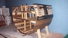
Backwards step…big step…little step
I was a bit disappointed when I painted all the ballast I had printed. In pictures of the HMS Victory the broad arrows on the iron pigs appear to be filled with dust from the shingle ballast. On the HMS Trincomalee the arrows are painted. Regardless, the arrows are noticeable so, after priming and painting all the pieces black, I experimented using some white weathering powder to fill the broad arrows. I was totally frustrated with poor results. I couldn’t keep the white off of the areas that needed to be black: washing, sanding, scraping all led to mottled grey
So…I bought black resin and printed all the ballast again. For those of you unfamiliar with resin 3D printing, there are many manufacturers of UV resin and many different formulations. Because of this variability there is always a bit of a learning phase to get good results with new resins. (This particular resin was eSUN’s plant-based product. If you want the settings I used please let me know). After several mediocre results I was able to start up the resin foundry into full production again.
I did find that some pieces were slightly bent after I cured them and I wasn’t sure which stage of the process was causing this. They appeared fine before I cut them off the supports, so I printed several more than I needed and experimented with post-printing procedures. (Again, if you’re interested just ask and I’ll fill you in on what I ended up doing.) Another perplexing issue was that there was an artifact from printing - diagonal lines on the larger ballast pieces that were printed facing in one direction - but the pieces printed in an opposite direction were smooth. In the resin world there is speculation that this is caused by the software used to prepare a 3d file for printing.
When time came to add the ballast to the model I realized that the first row, which runs perpendicular to the keel, was too long for my future plans so I had to cut it back. While this doesn’t seem to be a big deal to many, standard UV resins are remarkably brittle so I anticipated trouble. Either plant-based resins are more resilient than the standard formulae or I was careful enough to manage shortening them without mishap.
Something else became bothersome - sanding this resin produces a very fine, white (light grey?) powder that clung to everything. It almost became like paint and I had to scrub the ballast clean using water.
If I thought painting the hold was nerve-wracking enough, gluing these ballast pieces into place required a BIG gulp. I could always sand off paint, but once these are installed there’s no going back. It all worked fine. I didn’t bother painting the broad arrows on these starter rows because they will be hidden by a second tier - but parts of the rest of the ballast on this first tier will be visible in places. Therefore, I painted them using thinned, water-based Vallejo white and, once dry, scraped the paint off the surface of the ballast.
Now that I know the extent of the ballast I won’t install the second tier until later after some more work in the hold is done. Namely…
…the well and shot locker are next. It all starts with a cutaway main mast step. Poring over diagrams in Anatomy of the Ship: The Frigate Diana and AotS: The 23-Gun Frigate Pandora plus photos of the HMS Victory in Longridge’s The Anatomy of Nelson’s Ships - they seemed to indicate that the mortise for the main mast was cut through the mast step and the heel of the mast would sit on the keelson. Starting with a block of birch 4.0 mm x 3.0 mm x 15.0 mm, I carefully marked lines with a knife and, with a very sharp chisel and xacto knife, managed to fit it quite nicely around the keelson and limber strakes - complete with a mortise through to the keelson. In this process I discovered that there was a small warp in the keelson! A bit of filing messed up the paint, but I can easily touch that up.
I was very happy with the fit. That is, until…
I happened to spot a drawing in AotS: …Diana (p. 30) where I finally could see that the mortise was NOT cut through! Ok…I’m going to stop and collect my composure before deciding if I should repair or replace the nicely fitting step I made.
I think Number One wants this step off the ship…
-
Gabek reacted to Nirvana in HMS Triton by Gabek - 1:96 - cross-section
Gabe, another reason for me to get 3d printer up and running, unfortunate it's not a resin printer.
-
Gabek got a reaction from Nirvana in HMS Triton by Gabek - 1:96 - cross-section
Thanks, Mark!
Yeah, Number One is likely going to get his way. But it fits SO nicely...😭. Not sure if I can pull off another. I'm glad that I didn't glue it down right away!
AND, I did plan to write in the 3D forum very shortly and offer the .stl file I created.
Clear skies,
Gabe
-
Gabek got a reaction from mtaylor in HMS Triton by Gabek - 1:96 - cross-section
Thanks, Mark!
Yeah, Number One is likely going to get his way. But it fits SO nicely...😭. Not sure if I can pull off another. I'm glad that I didn't glue it down right away!
AND, I did plan to write in the 3D forum very shortly and offer the .stl file I created.
Clear skies,
Gabe
-
Gabek reacted to mtaylor in HMS Triton by Gabek - 1:96 - cross-section
Nice work on the ballast, Gabe. As for the mortise, I suspect Number One will get his way inspite of protests from the yard workers.
BTW, you might consider a post in the 3D printing area on the ballasts you did.
-
Gabek got a reaction from mtaylor in HMS Triton by Gabek - 1:96 - cross-section
Backwards step…big step…little step
I was a bit disappointed when I painted all the ballast I had printed. In pictures of the HMS Victory the broad arrows on the iron pigs appear to be filled with dust from the shingle ballast. On the HMS Trincomalee the arrows are painted. Regardless, the arrows are noticeable so, after priming and painting all the pieces black, I experimented using some white weathering powder to fill the broad arrows. I was totally frustrated with poor results. I couldn’t keep the white off of the areas that needed to be black: washing, sanding, scraping all led to mottled grey
So…I bought black resin and printed all the ballast again. For those of you unfamiliar with resin 3D printing, there are many manufacturers of UV resin and many different formulations. Because of this variability there is always a bit of a learning phase to get good results with new resins. (This particular resin was eSUN’s plant-based product. If you want the settings I used please let me know). After several mediocre results I was able to start up the resin foundry into full production again.
I did find that some pieces were slightly bent after I cured them and I wasn’t sure which stage of the process was causing this. They appeared fine before I cut them off the supports, so I printed several more than I needed and experimented with post-printing procedures. (Again, if you’re interested just ask and I’ll fill you in on what I ended up doing.) Another perplexing issue was that there was an artifact from printing - diagonal lines on the larger ballast pieces that were printed facing in one direction - but the pieces printed in an opposite direction were smooth. In the resin world there is speculation that this is caused by the software used to prepare a 3d file for printing.
When time came to add the ballast to the model I realized that the first row, which runs perpendicular to the keel, was too long for my future plans so I had to cut it back. While this doesn’t seem to be a big deal to many, standard UV resins are remarkably brittle so I anticipated trouble. Either plant-based resins are more resilient than the standard formulae or I was careful enough to manage shortening them without mishap.
Something else became bothersome - sanding this resin produces a very fine, white (light grey?) powder that clung to everything. It almost became like paint and I had to scrub the ballast clean using water.
If I thought painting the hold was nerve-wracking enough, gluing these ballast pieces into place required a BIG gulp. I could always sand off paint, but once these are installed there’s no going back. It all worked fine. I didn’t bother painting the broad arrows on these starter rows because they will be hidden by a second tier - but parts of the rest of the ballast on this first tier will be visible in places. Therefore, I painted them using thinned, water-based Vallejo white and, once dry, scraped the paint off the surface of the ballast.
Now that I know the extent of the ballast I won’t install the second tier until later after some more work in the hold is done. Namely…
…the well and shot locker are next. It all starts with a cutaway main mast step. Poring over diagrams in Anatomy of the Ship: The Frigate Diana and AotS: The 23-Gun Frigate Pandora plus photos of the HMS Victory in Longridge’s The Anatomy of Nelson’s Ships - they seemed to indicate that the mortise for the main mast was cut through the mast step and the heel of the mast would sit on the keelson. Starting with a block of birch 4.0 mm x 3.0 mm x 15.0 mm, I carefully marked lines with a knife and, with a very sharp chisel and xacto knife, managed to fit it quite nicely around the keelson and limber strakes - complete with a mortise through to the keelson. In this process I discovered that there was a small warp in the keelson! A bit of filing messed up the paint, but I can easily touch that up.
I was very happy with the fit. That is, until…
I happened to spot a drawing in AotS: …Diana (p. 30) where I finally could see that the mortise was NOT cut through! Ok…I’m going to stop and collect my composure before deciding if I should repair or replace the nicely fitting step I made.
I think Number One wants this step off the ship…