.jpg.6c90d67e7e9071af590f4d4a2a8bc908.jpg)
Waldemar
-
Posts
1,003 -
Joined
Content Type
Profiles
Forums
Gallery
Events
Everything posted by Waldemar
-
.thumb.jpg.c6343966b029e7941df5b987d129aac6.jpg)
Paviljoensjacht 1733 | Blender
Waldemar replied to Robska's topic in CAD and 3D Modelling/Drafting Plans with Software
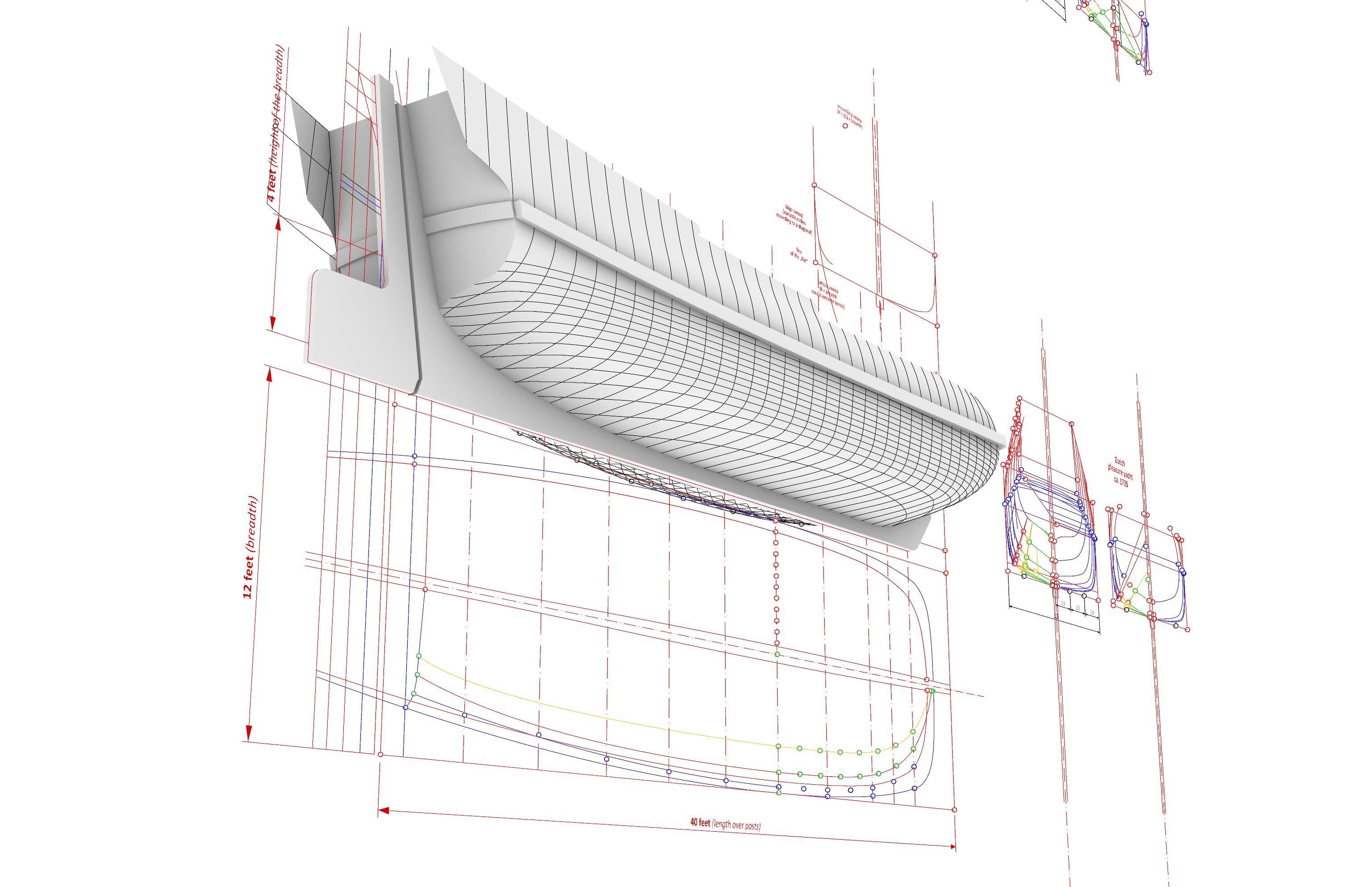
Voilà! The lines of your yacht are ready. Since you will be processing it further in the 3D program, I will not be doing 2D drawings as I did previously. Instead, I will send it to you right away via PM in OBJ format. just as you see it below, only without all those design lines which you don't need, just the surfaces themselves.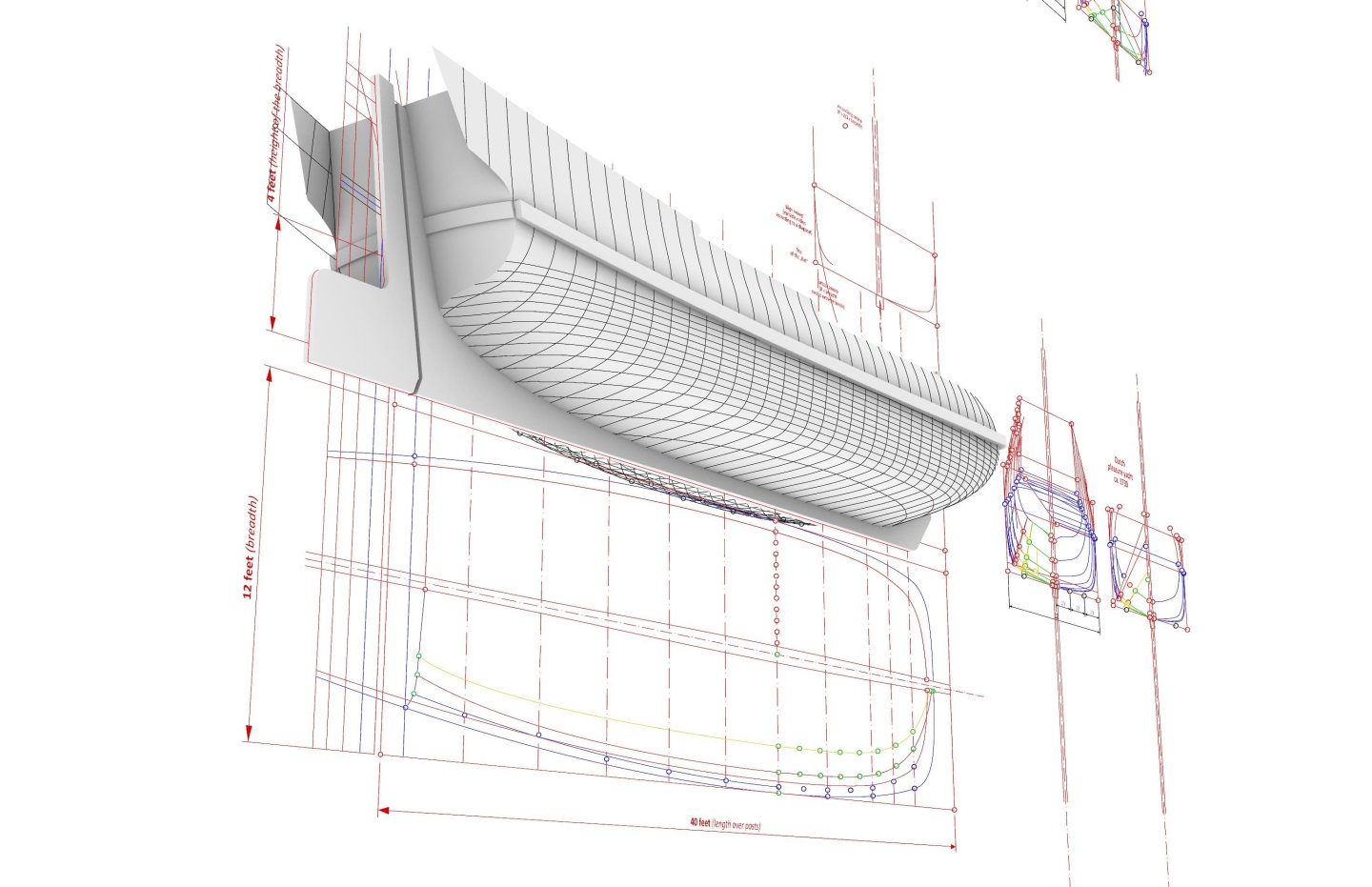
-
Paviljoensjacht 1733 | Blender
Waldemar replied to Robska's topic in CAD and 3D Modelling/Drafting Plans with Software
Almost finished...
-
Paviljoensjacht 1733 | Blender
Waldemar replied to Robska's topic in CAD and 3D Modelling/Drafting Plans with Software
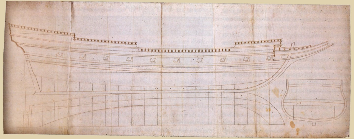
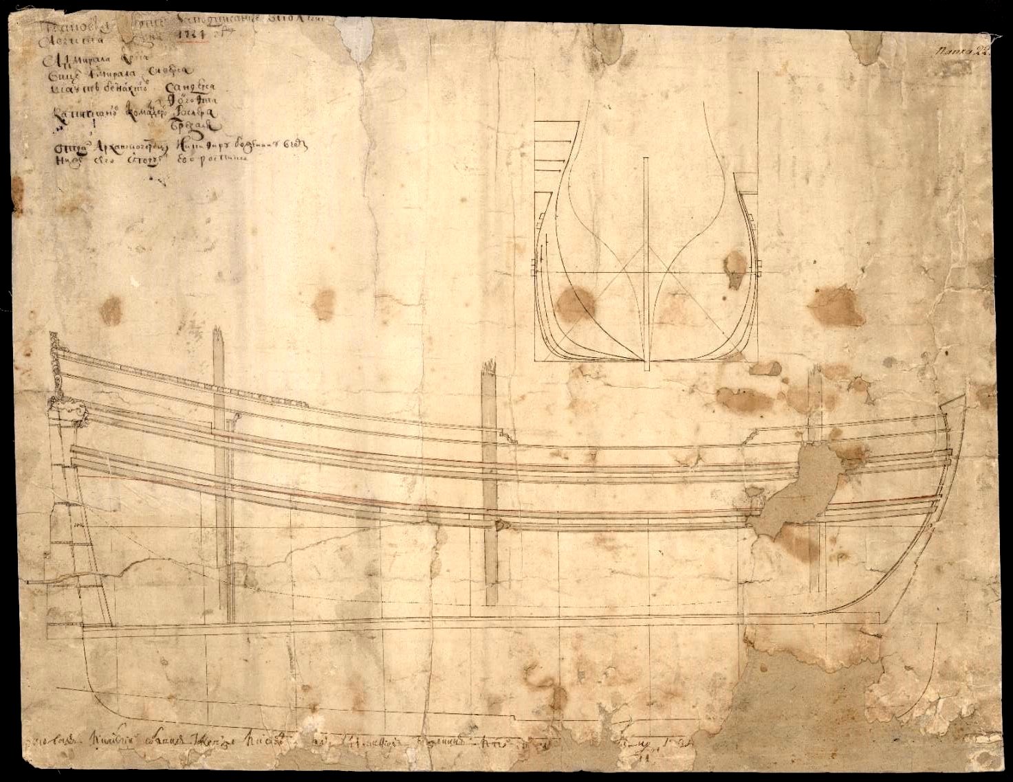
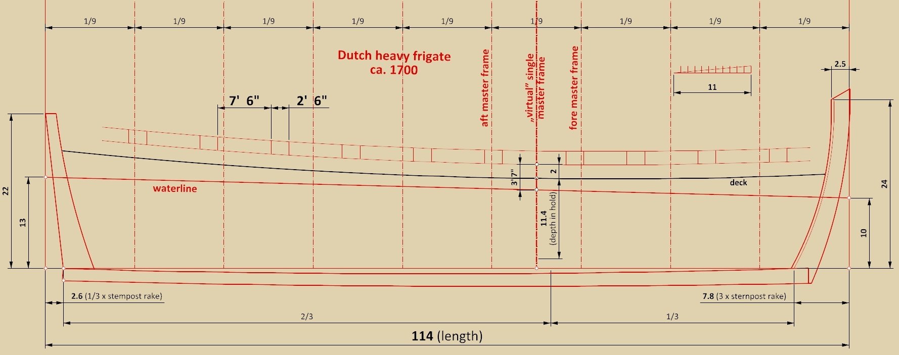
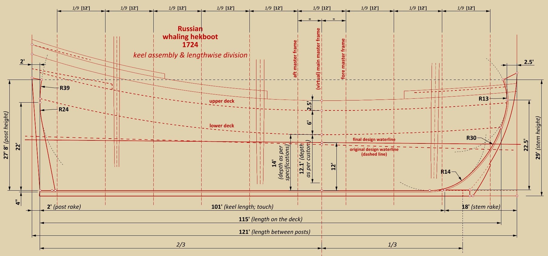
Without going into considerations of an academic nature, I will only say that the design of the yacht under consideration is quite detailed for its era and certainly made it possible to build a vessel. For comparison, let me remind of a design from about the same period, according to which a whole series of three whaling ships were successfully built. Please note how ‘poor’ in detail this design is in its graphic form: And yet another design from a couple of decades earlier. Here, not even contours of the bends are defined, and yet this very design was again a base for successful building a whole series of ships: To make a long story short, the content of the book you mention focuses on the „modern” design methods, adopted in the Netherlands by some designers around the second quarter of the 18th century, which in essence are methods adapted from the so-called French methods, in the meaning of using numerous diagonals that were harmoniously divided geometrically or mathematically to obtain the contours of the frames, independently of the traditional design lines such as the line of the floor used up to then. This is already a completely different era in terms of naval architecture compared to the design techniques native to the 17th century and earlier. More on this fully diagonal methods, please see, for example, the excellent works of Jean Boudriot on the subject.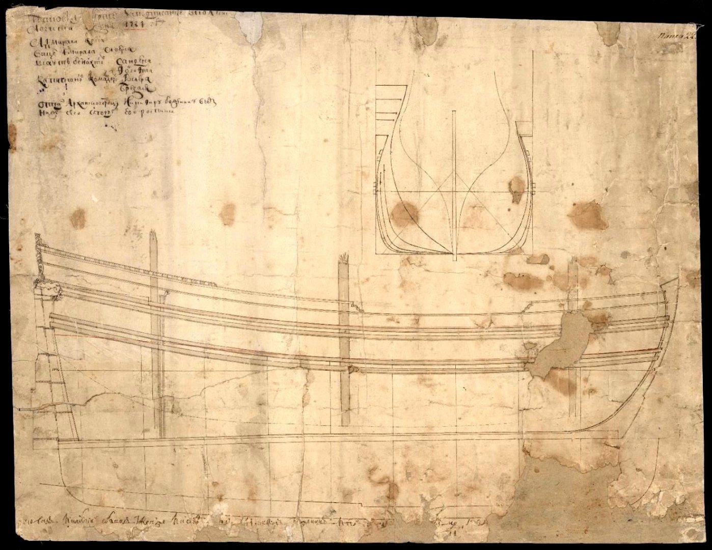
-
Paviljoensjacht 1733 | Blender
Waldemar replied to Robska's topic in CAD and 3D Modelling/Drafting Plans with Software
I am always assertive or honest. Unless the demands of courtesy and politeness sometimes get in the way 🙂. I keep hoping that someone will eventually start applying these presented design methods themselves. That is at least the general intention. But in this particular case of this yacht I was going to do it anyway, so I don't see it as a problem to take the extra time to do some additional drafting of simple 2D plans, as I have already done for Samuel 1650 at Don's request. Does this convention suit you more or less? Further on, you will already be on your own. -
Paviljoensjacht 1733 | Blender
Waldemar replied to Robska's topic in CAD and 3D Modelling/Drafting Plans with Software
There is probably no need to guess. There are at least a dozen plans in the archives created obviously by one hand and this very plan is in that group. One of these plans is signed by its designer, a certain Jan Veltmand, and another plan, of a hooker, shows even the name of the ship – ‘Catharina Maria’. It would be enough to check this information to get more exact dating. I personally rely provisionally on the archivists' dating, which seems to me quite acceptable, given the specifics of these designs. Besides, they are kept together with other plans, with dates on them, for example 1728 and 1733. I wonder how one can be sure that they were not used to built actual vessels? In any case, these plans must have been drawn somehow, after all, and all indications are that they are not random scribbles. Here, too, there is no need to guess. I am familiar with the contents of this publication, which is why, among other things, I wrote that the method identified from this plan is so far unknown. Incidentally, other Dutch design methods from the first decades of the 18th century and earlier are also not described in this book. There are at most comments on the plans reproduced there from that very earlier period, of the kind that it is not known how they were designed. By the way, in this group of a dozen drawings by Jan Veltmand there is a plan with a rather similar general layout, that is, with a central cabin and a deep cockpit, itself before a very small cabin aft (National Archief NL-HaNA_4.MST_470) :
-
Paviljoensjacht 1733 | Blender
Waldemar replied to Robska's topic in CAD and 3D Modelling/Drafting Plans with Software
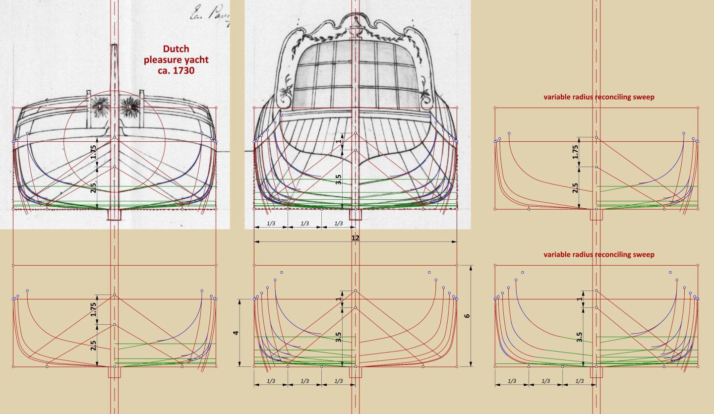
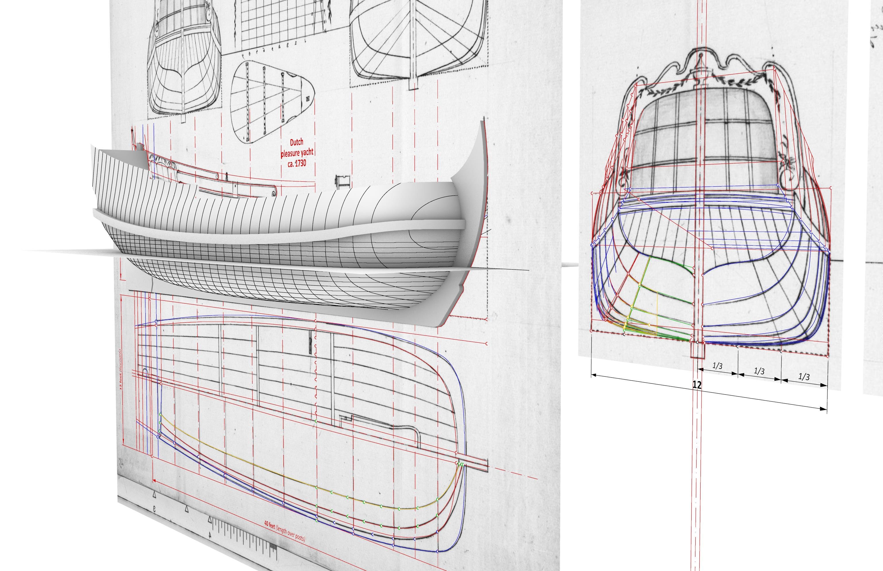
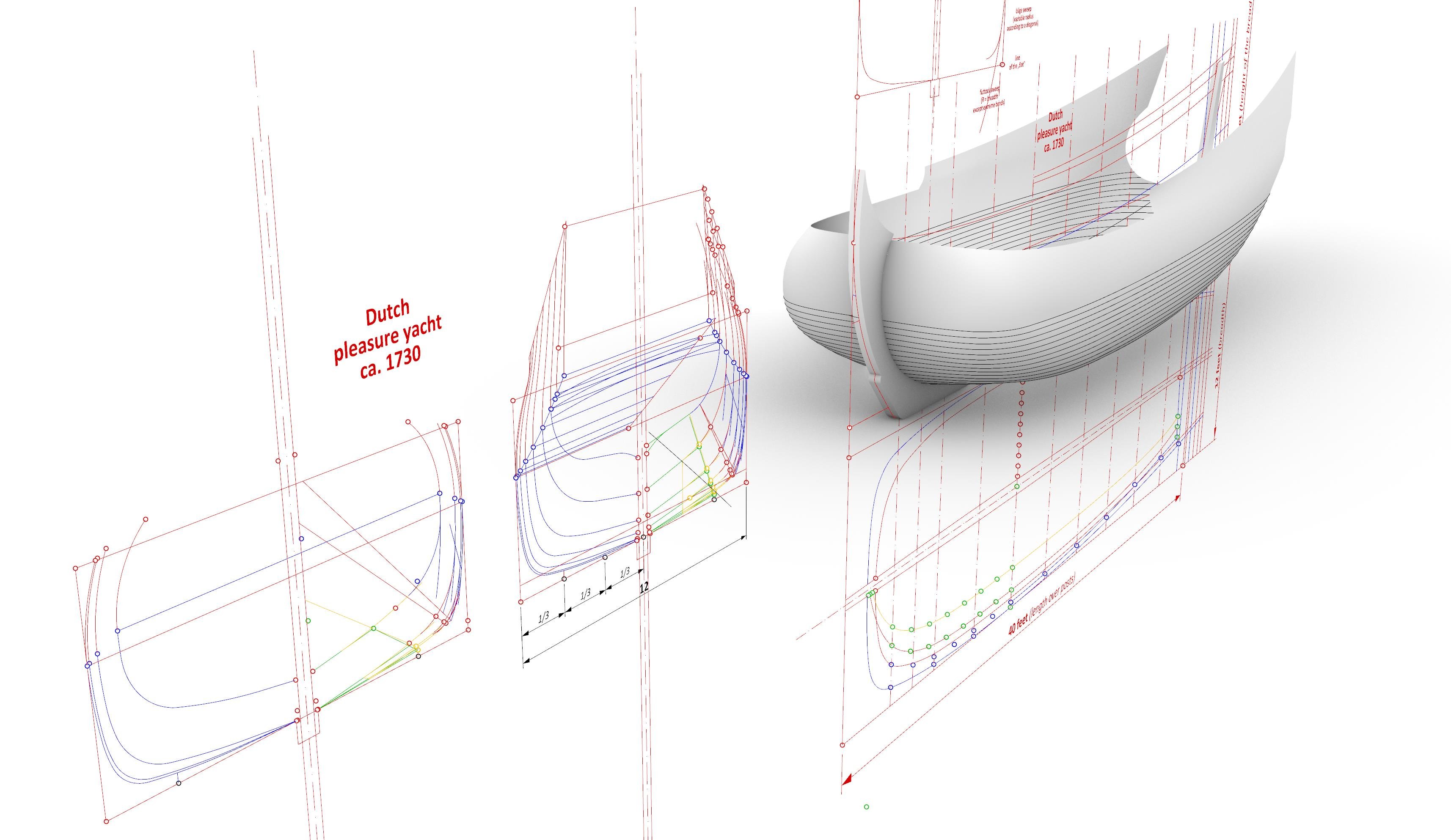
Hi, thanks, but it should actually read ‘Jan points in his post #11’ 🙂. Quoting and reproduction for non-commercial purposes is not prohibited, at least according to the law to which I am subject, so below is a copy of that plan whose existence you have reminded us of. Indeed, it's a great example, and even for several reasons, thanks. Meanwhile, I took an even closer look at the design concept of the yacht we are talking about. This method, already using design diagonals to produce variable radii, is simply brilliant in its simplicity and ingenuity at the same time. I think I'll make a separate thread describing this as yet unknown method, discovered thanks to this plan. For now, below, I am posting the almost finished body plan of this yacht. You can see quite well all the drawing inaccuracies committed in the original drawing, but it should be noted right away that more precision was not necessary to draw such a preparatory sketch, as precise tracing was only required on the mould loft. This is also another very good opportunity to show the potential of reverse engineering that takes into account old design methods. Not only does this approach not introduce new distortions when smoothing out hull shapes, but it also further corrects the designers' frequent drawing inaccuracies and later distortions of the original drawings.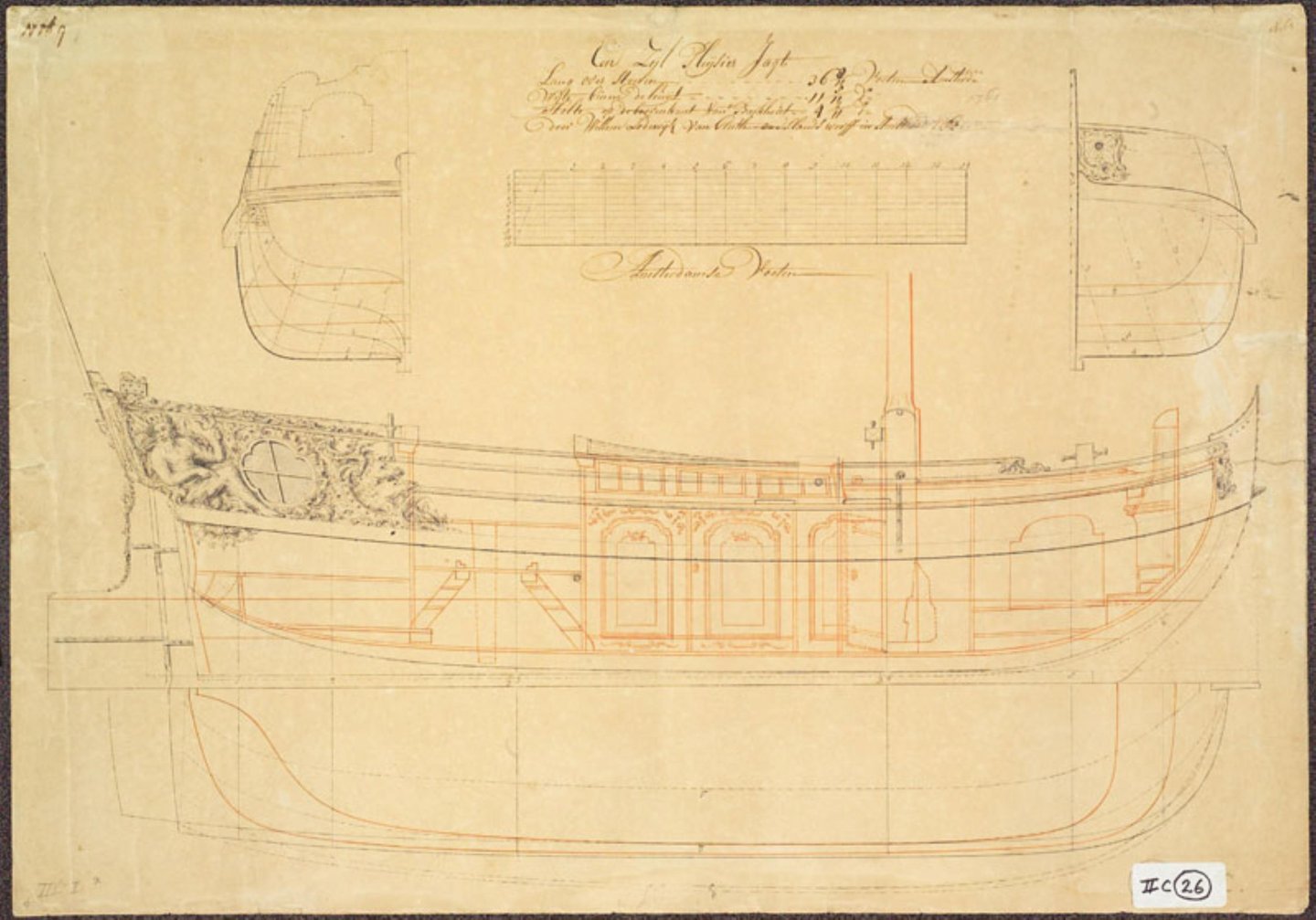
-
There is quite a significant difference in the shaping of the hollowing/bottom curves in Steel's and Stalkartt's work. While the former uses a very traditional way, going at least back to the antiquity, by using a properly curved and scaled wooden template (related to non-graphical methods, i.e. without paper plans), the latter has a different way: simple straight lines for the central part of the hull, much more convenient to draw on paper plans, and the bends/frames at the extremities of the hull are even shaped in their entirety on the basis of previously drawn waterlines (such approach is strictly related to newer, graphical methods of designing). But it is already your job to recognise such specificities in the drawing you are examining 🙂.
-
Yes, on the one hand this is true. And there are many more such arbitrarily chosen design components in Stalkartt's description. And not without reason, as he describes things in a most valuable, universal way, that is, he lists all these design components, explains what they serve and how they are applied and in what order. Precisely consciously in the most universal way possible, independent of the specific parameters used by individual designers and for various types of boats. Today, without this background knowledge, it is not at all easy to reproduce the design process even with the original plans. It is therefore usual to redraw the lines from the extant plans and then smooth them out by various means. This present-day alternative method is also good for specific goals, but has its own peculiarities and limitations. Yes, plate I and pages 1–28 on whole-moulding.
-
Paviljoensjacht 1733 | Blender
Waldemar replied to Robska's topic in CAD and 3D Modelling/Drafting Plans with Software
Right, definitely 40 feet. Confirmed by direct application of the drawn linear scale. I also looked at the method of forming the hull shapes. In its essence, it is not overly complicated, but recreating the main design lines, which have been scrupulously erased from the finished draught, would already be an undertaking for at least a couple of days. This could be quite an interesting reverse-engineering project in itself, as I have not yet investigated such a variant of Dutch-style design. These old methods, correctly applied, actually guarantee perfectly faired shapes.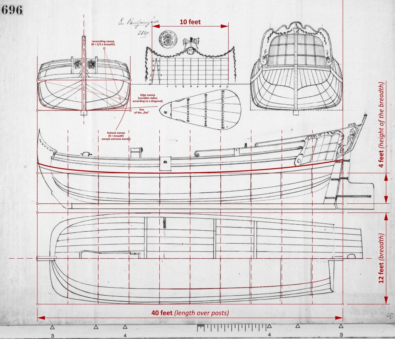
-
Oh my...! I feel a little guilty now, because it's like you're starting to follow my footsteps into the abyss of madness 🙂. Or, into a hitherto hardly explored space. I didn't expect you to approach it in such a meticulous way... Anyway, one can see a lot of regularities on your numerical chart, which clearly suggest that the designer used the same procedure and set of proportions in most of the cases you measured. This kind of juxtaposition can help you to reveal the design logic of this particular boat, if that is your wish and intention. However, as you are already aware, such a method and sequence of ships' boats design is described in both of Steel's works (The Elements and Practice of Naval Architecture 1805 and The Shipwright's Vade-Mecum 1805), but probably best and most comprehensively in Naval Architecture 1787 by Marmaduke Stalkartt. More and more publications are being made publicly available by archives and libraries these days, but if you can't find the latter work but still want to consult it, I'll do the scans for you. Just please check availability on the internet resources first, as it is quite a lot of scanning (a whole 28 pages of textual description plus a very large drawing sheet, which I would have to scan six or eight times and then stitch together). Please let me know.
-
Paviljoensjacht 1733 | Blender
Waldemar replied to Robska's topic in CAD and 3D Modelling/Drafting Plans with Software
Well, yes and no. On the side view, the contours of the front cabin are indeed not drawn, nevertheless, on the other hand, there are two beams on the top view which would correspond very neatly to both bulkheads of this very cabin. Coincidentally, they also limit in a very convenient way the length of this special doble plank for fixing the leeboard axle. Please note also the lack of continuation of the plank seams on the top projection, which may be intentional. Please do not take my diagram in too literal a manner. It is simply a quick sketch not quite to scale, the intention of which was to show the essence of the configuration, not the exact dimensions. And indeed, this is particularly true of the floor height as well as the height of the roof of the front cabin, which would both obviously need to be corrected or optimised at a later stage. But since you are dismissing this particular concept sporting a deep cockpit, incidentally quite attractive or convincing, it would already be a rather unnecessary exercise anyway... -
Paviljoensjacht 1733 | Blender
Waldemar replied to Robska's topic in CAD and 3D Modelling/Drafting Plans with Software
Ordinary deck planks are indeed not structural elements, like the planks of the side, but the waterway, i.e. the outermost, hefty deck plank at the very side of the ship already is. And on this plan, the plank to which the leeboard axle is attached is even twice as wide as the others, one can assume not without reason. As well as robustness, it is equally about the simplicity of the solution, durability, ease of implementation and eventual repairs etc. One thing can be sacrificed for another. -
Paviljoensjacht 1733 | Blender
Waldemar replied to Robska's topic in CAD and 3D Modelling/Drafting Plans with Software
@Robska From an engineering point of view, fixing the leeboard as on this plan, i.e. to the deck, is preferable (more robust) to fixing only to the side of the ship. -
Paviljoensjacht 1733 | Blender
Waldemar replied to Robska's topic in CAD and 3D Modelling/Drafting Plans with Software
Such a configuration as below? Yes, this is a very convincing arrangement.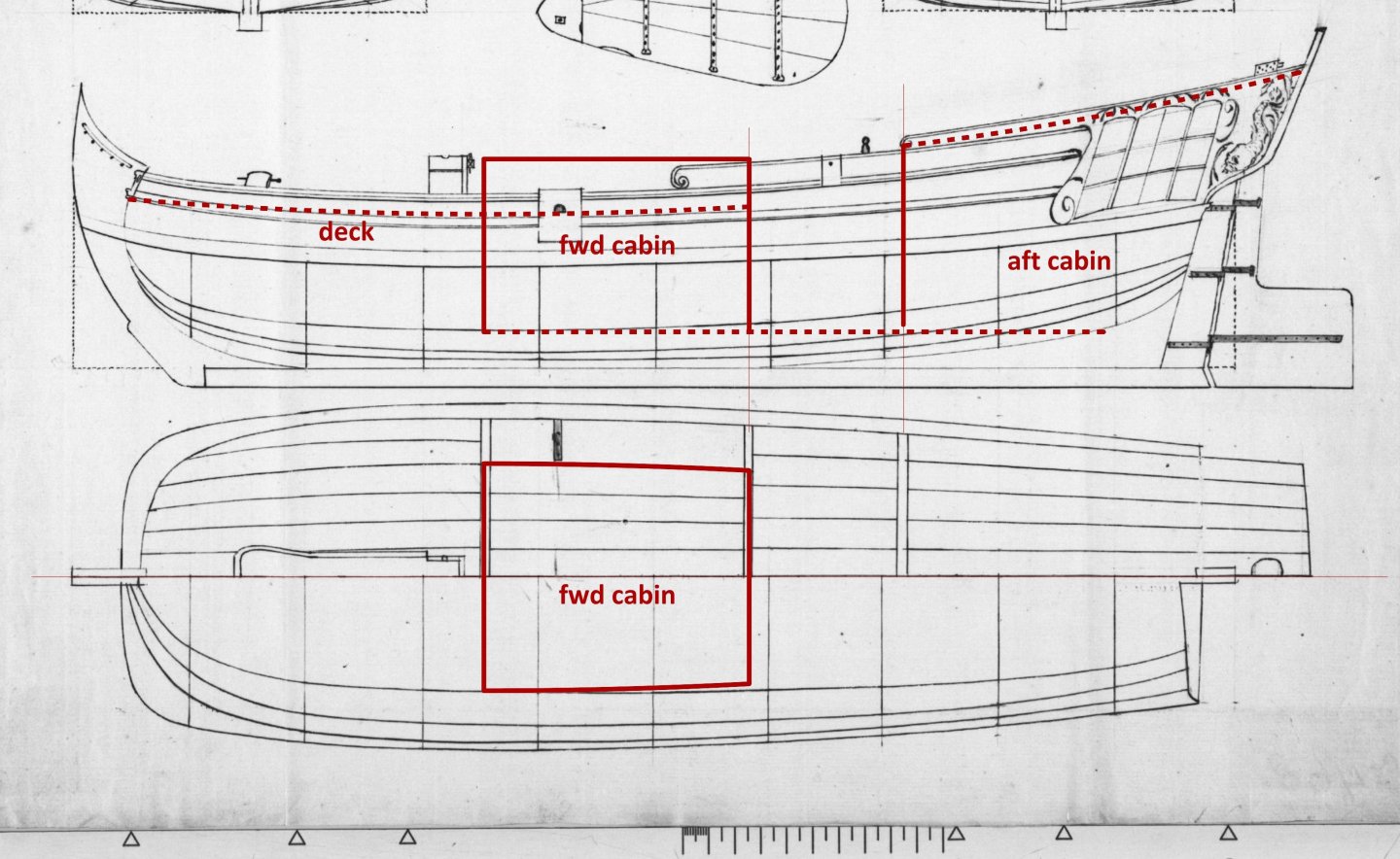
-
Paviljoensjacht 1733 | Blender
Waldemar replied to Robska's topic in CAD and 3D Modelling/Drafting Plans with Software
As a result, you would get a more or less similar deck configuration: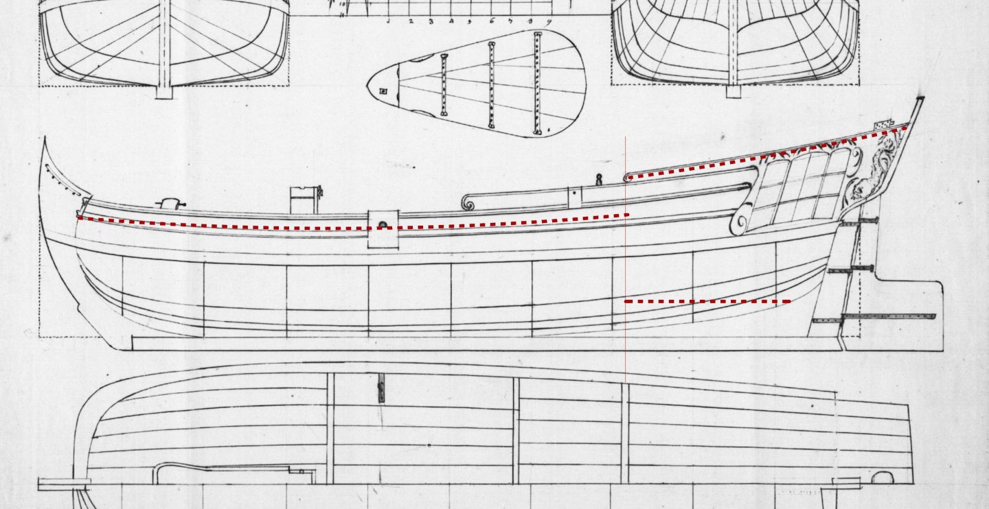
-
Paviljoensjacht 1733 | Blender
Waldemar replied to Robska's topic in CAD and 3D Modelling/Drafting Plans with Software
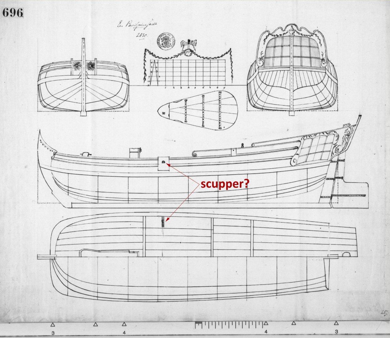
Of the two, however, I like the leeboard mount variant better. Yes, if it were a scupper, it would set the level of the deck. However, this iron pin may be attached directly to the deck; in the close-up you can see three dots presumably marking the heads of the attaching nails. -
Paviljoensjacht 1733 | Blender
Waldemar replied to Robska's topic in CAD and 3D Modelling/Drafting Plans with Software
-
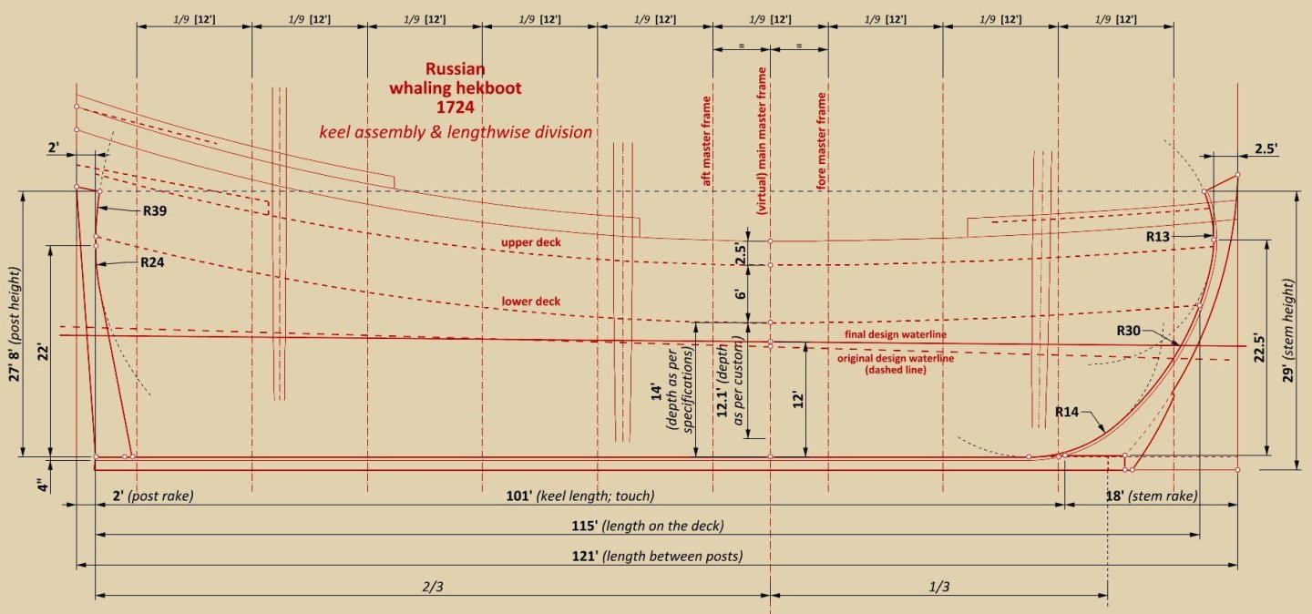
Here, please, are some examples with similar attempts. They relate to different periods, places and design methods. I have deliberately cited such a broad spectrum here to show the variety of solutions used by designers of the time. Within a narrower range, for example in terms of time or relating to the same design method, one can find regularities, but today, in practice, one still has to check the various possible variants each time when analysing such plans. In general, when looking for such proportions, start with the smallest integers that divide the reference length. Increase these numbers until you get an adequate correspondence with the plan under examination. Usually the result is below 10, but in one of the examples shown it is as high as 20. But in fact the greatest difficulty is to find out the correct reference length to divide (or to compare, which, for example, applies to the posts rakes). Ideally, you simply need to check them all, as I mentioned in entry #12. Note: the first three examples show designs sporting the so-called double master frame, which are not applicable to your particular project of a boat, however the other details are or may be analogous.

-
What is the origin of the tables of offsets? Not a previously produced design drawing? 🙂 As a curiosity — in a work published in 1711, William Sutherland proposed a new way of designing. He cited as one of its major advantages the possibility of achieving greater precision in tracing the lines compared to the traditional way, and consequently less waste of time, material and energy on dubbing.
-
Arthur, if you decide to investigate this at all, especially the lengthwise position of the master frame and the like, I'll just hint, just to be safe, that Rhino's command ‘divide curve by number of segments’, is very handy for this purpose.
-
Nice. And what about trying to find the lengthwise position of the master frame in a proportional rather than just dimensional way? There are several possibilities to check – as a reference length you might eventually find the length between perpendiculars, the length between posts (if different from the previous one), the length of the waterline or the length of the keel (both tread and touch). You could also check the ratio between rakes of the stem and stern posts. And their ratio to the total length as well, both individually and as the sum of the two.
-
A very good and reasonable approach, so as not to say that the only truly satisfactory.
-
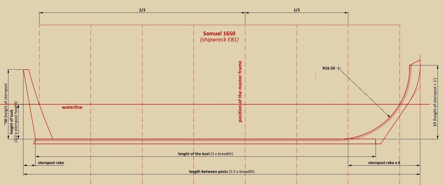
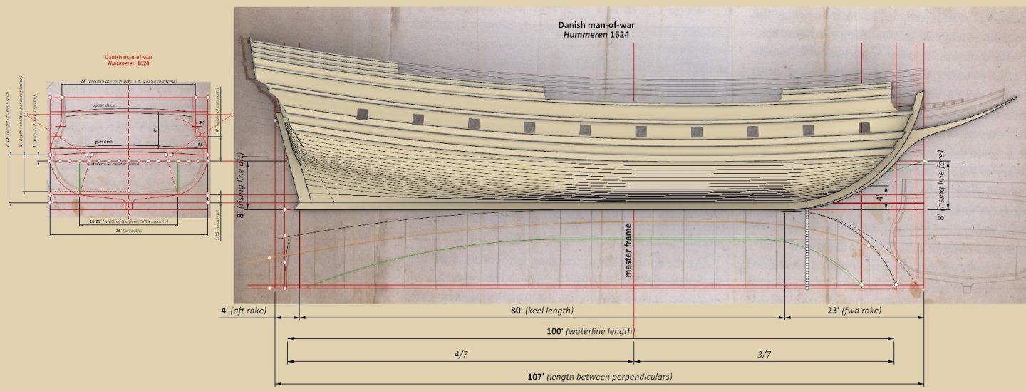
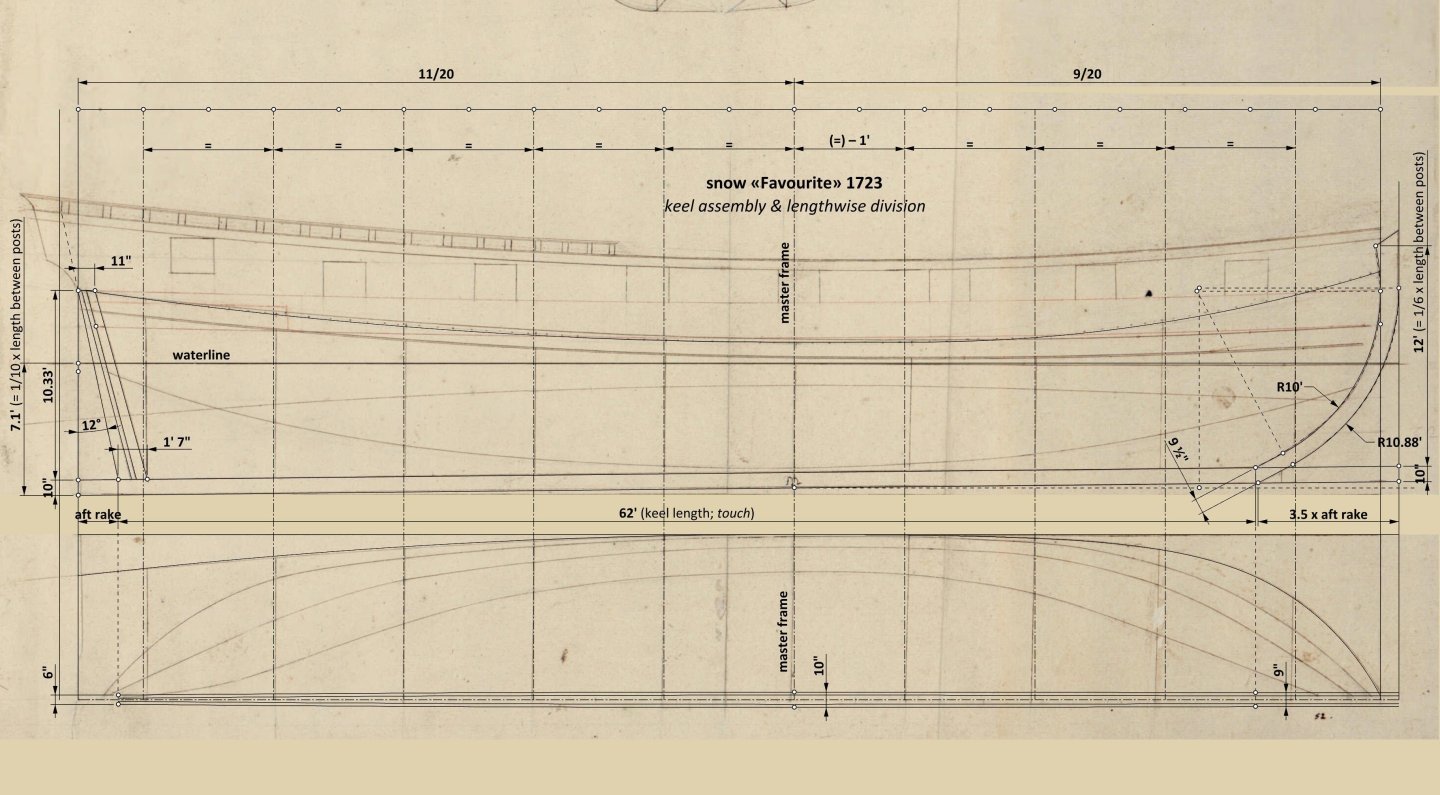
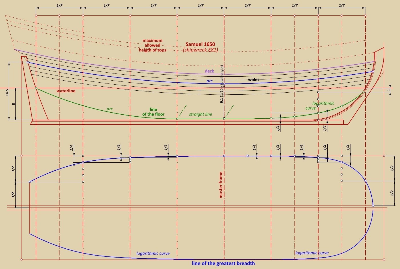
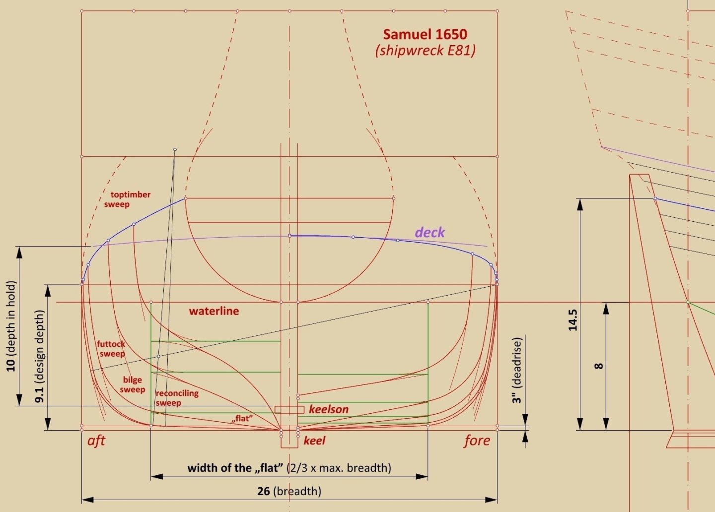
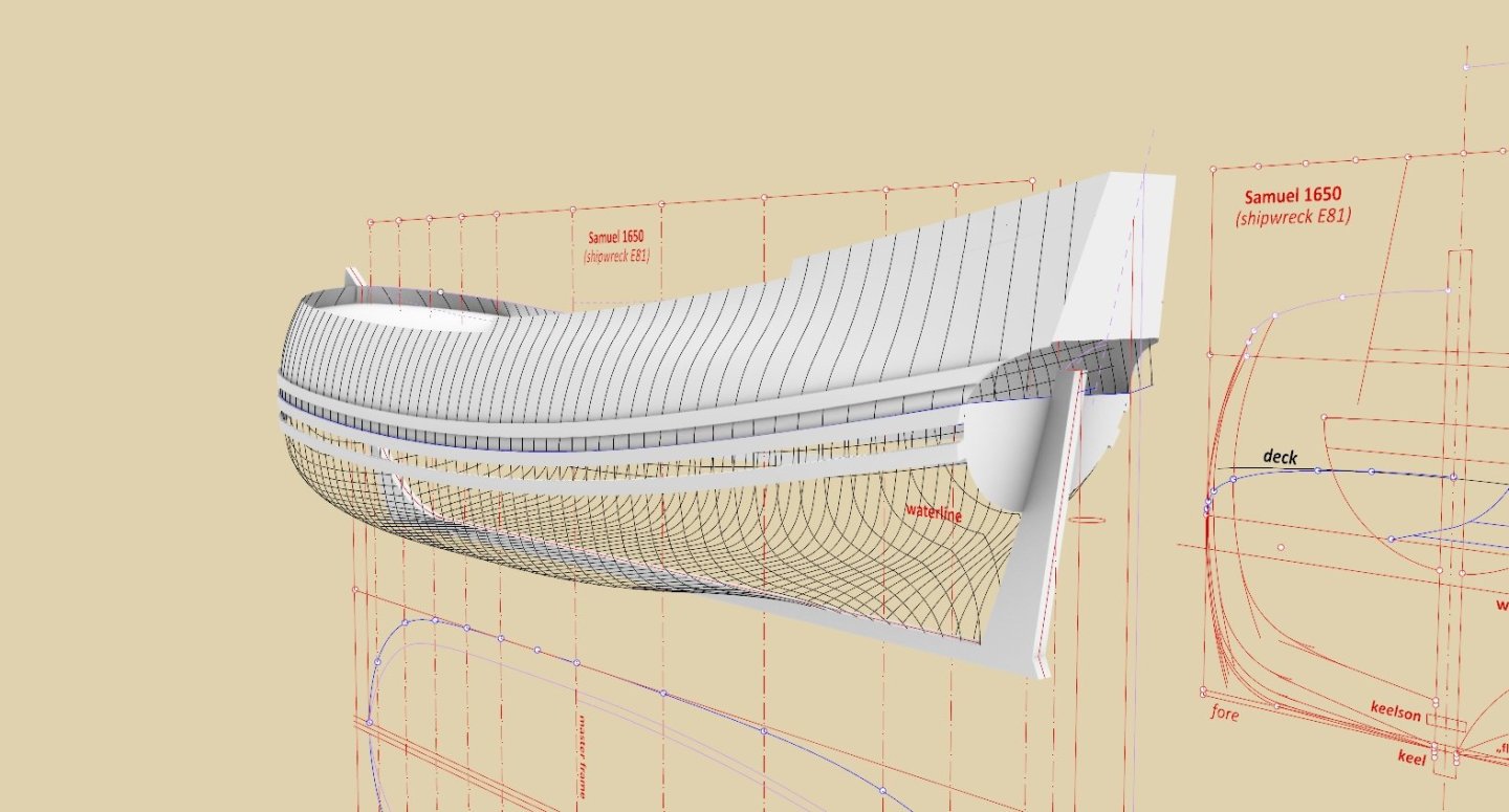
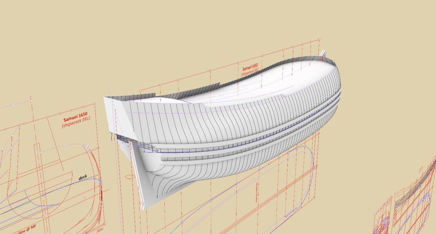
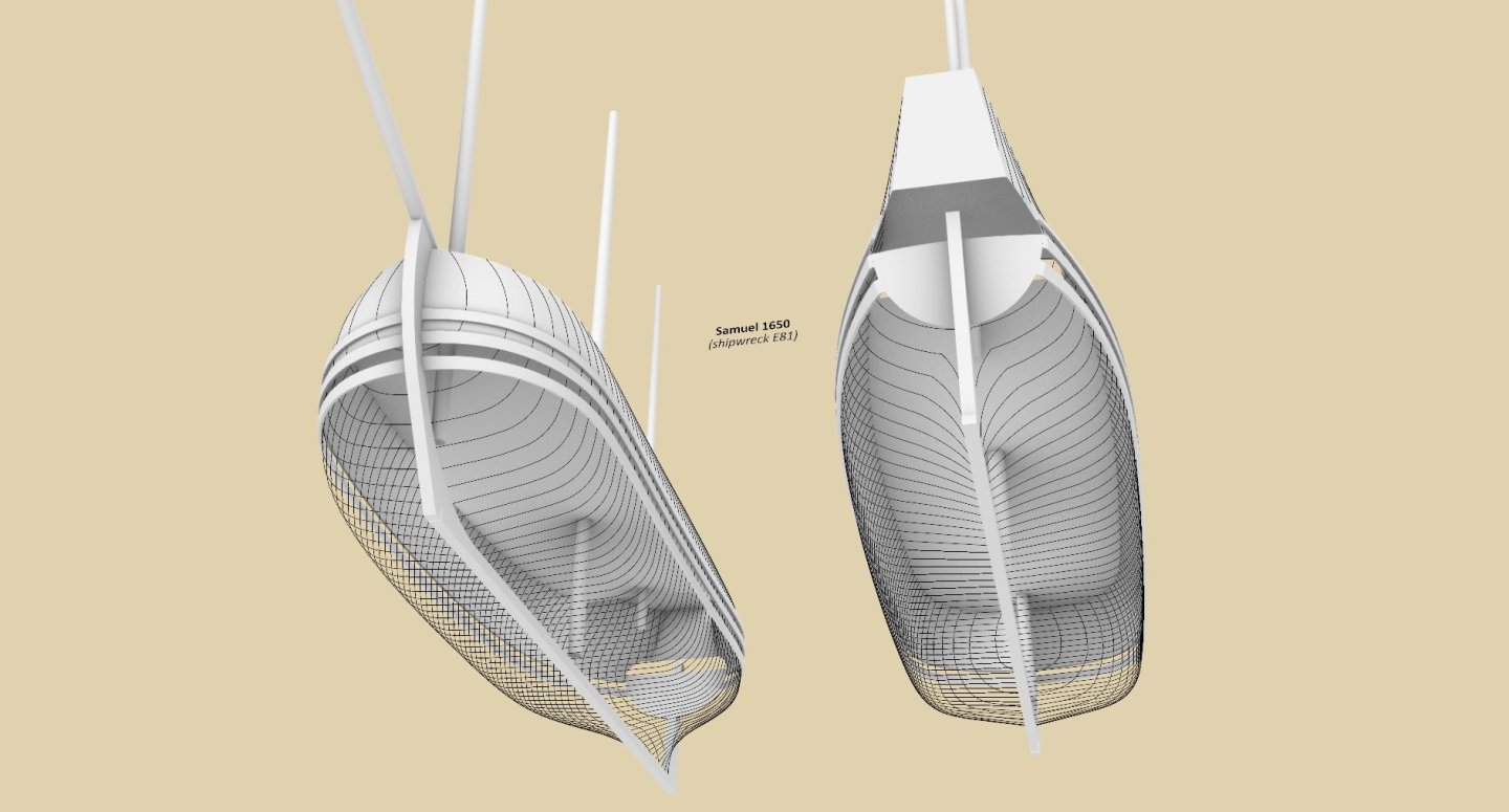
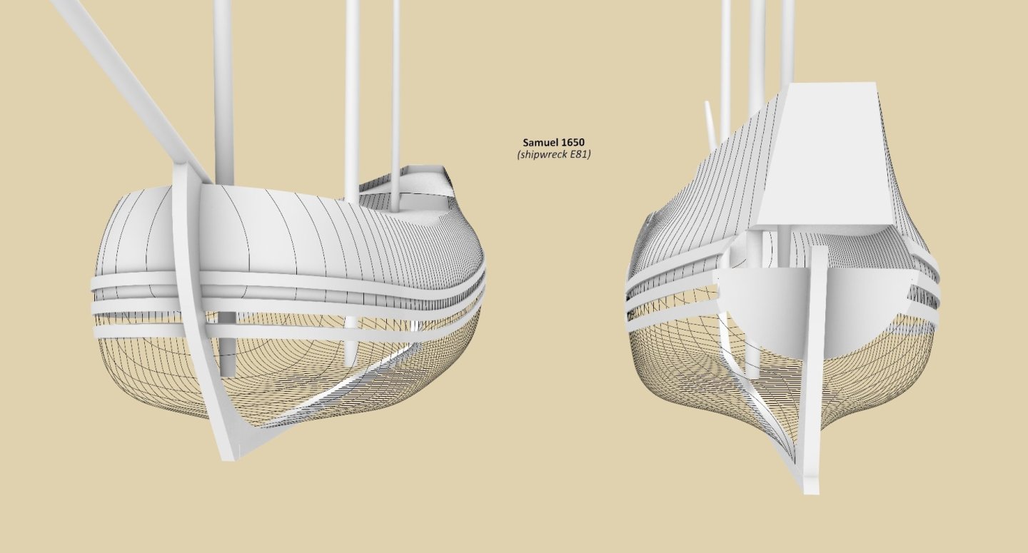
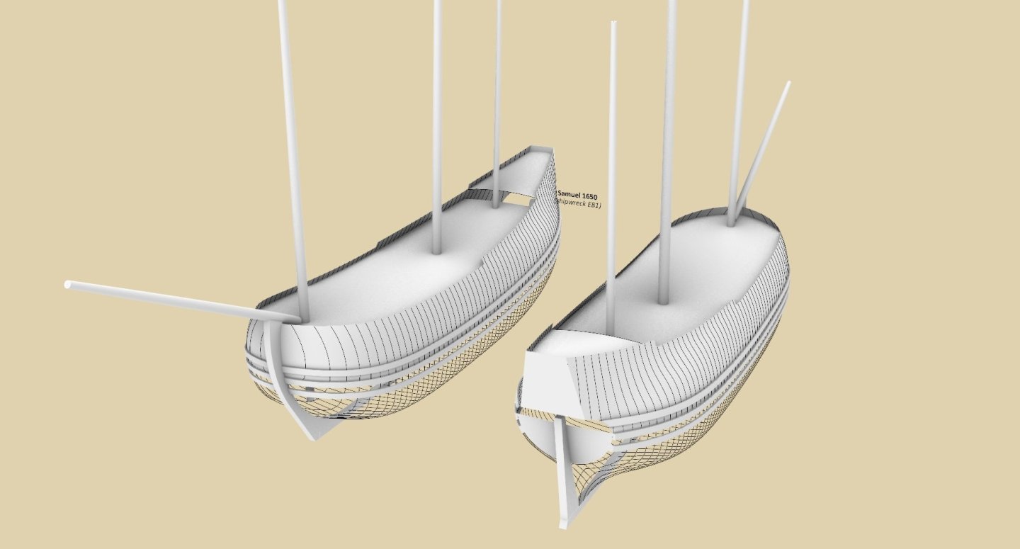
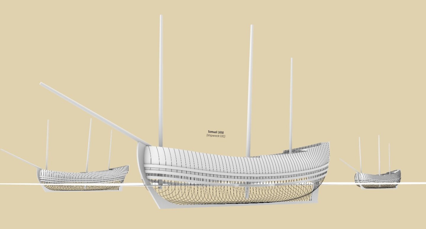
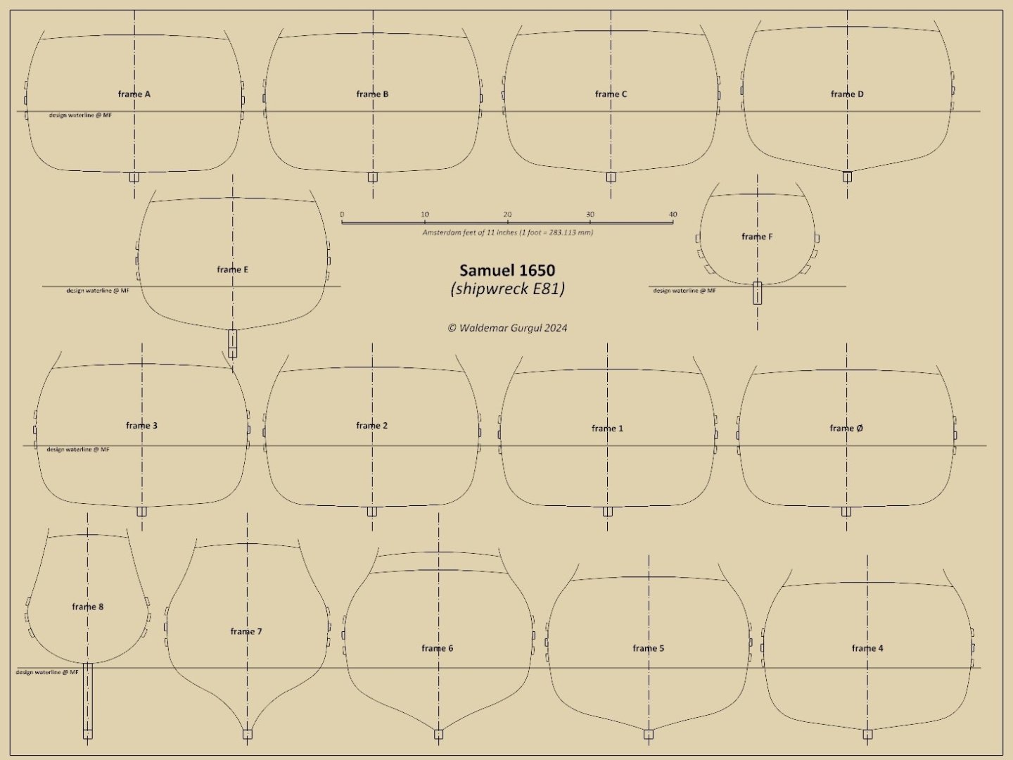
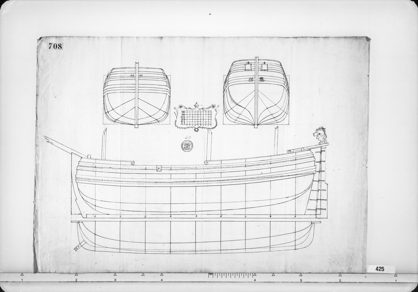
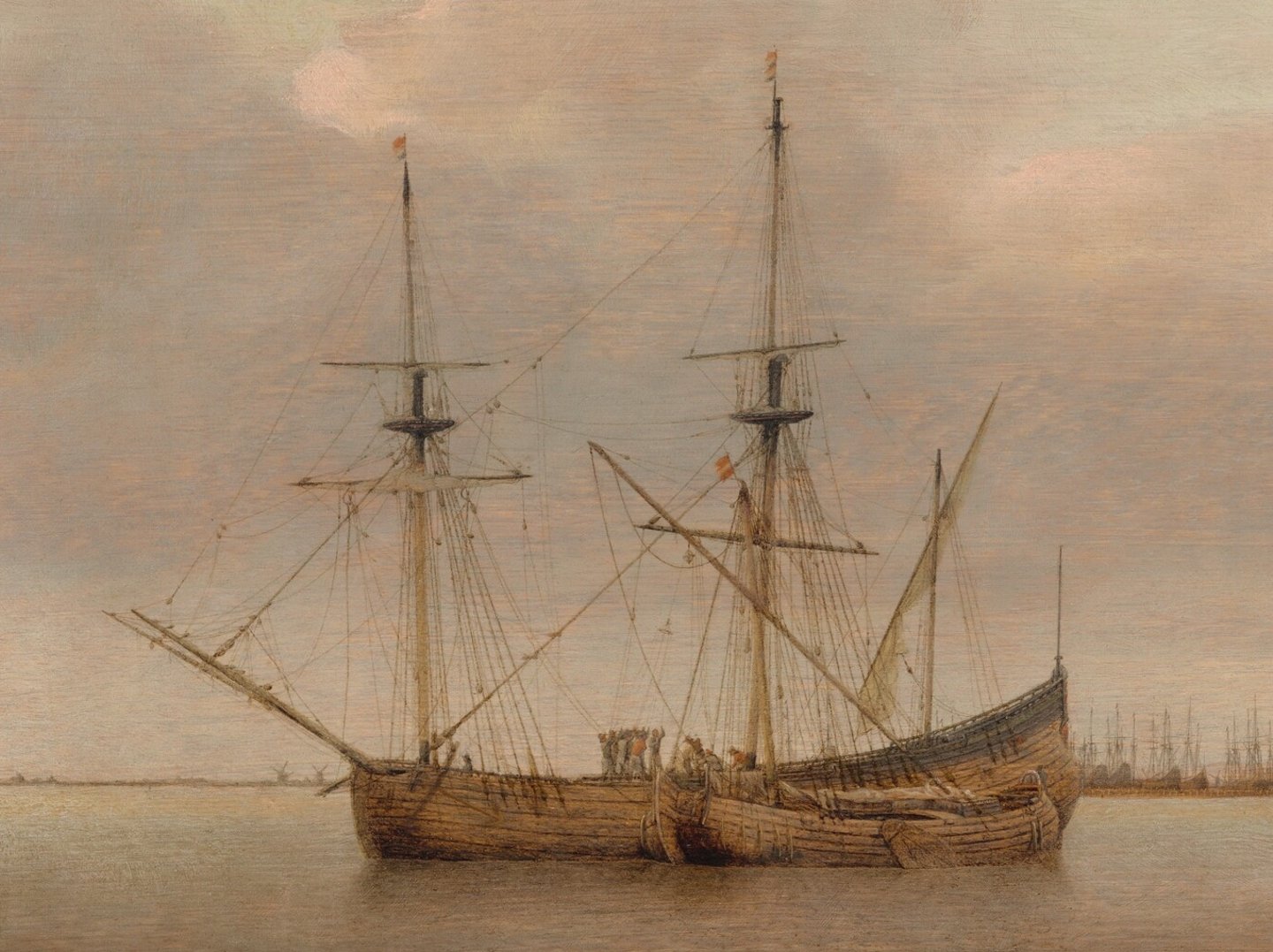
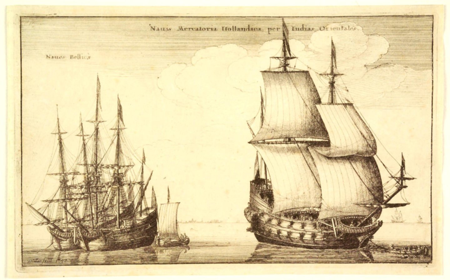
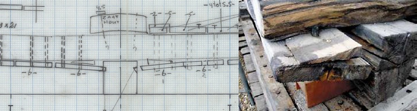
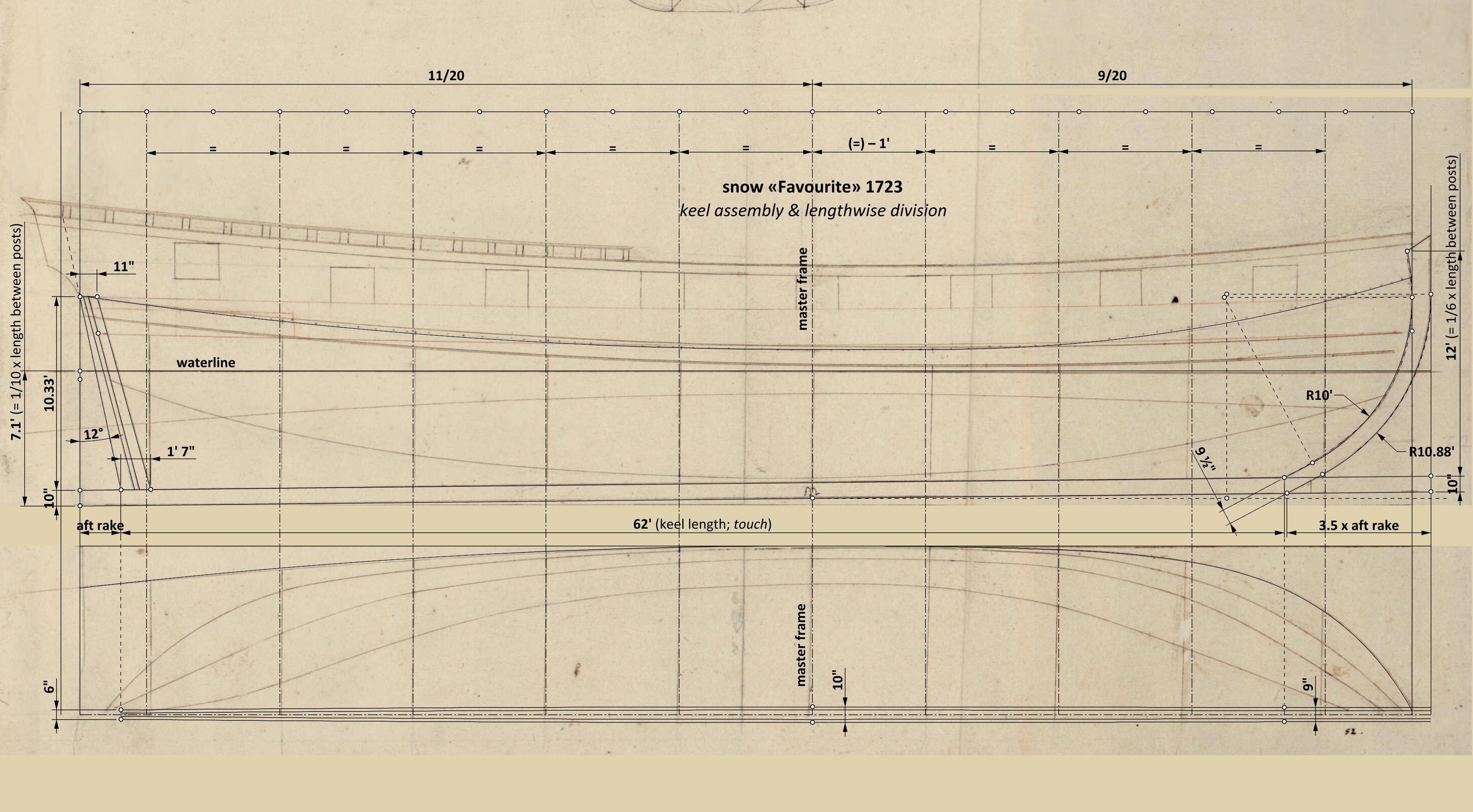
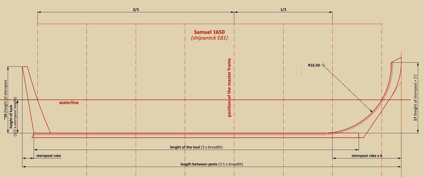
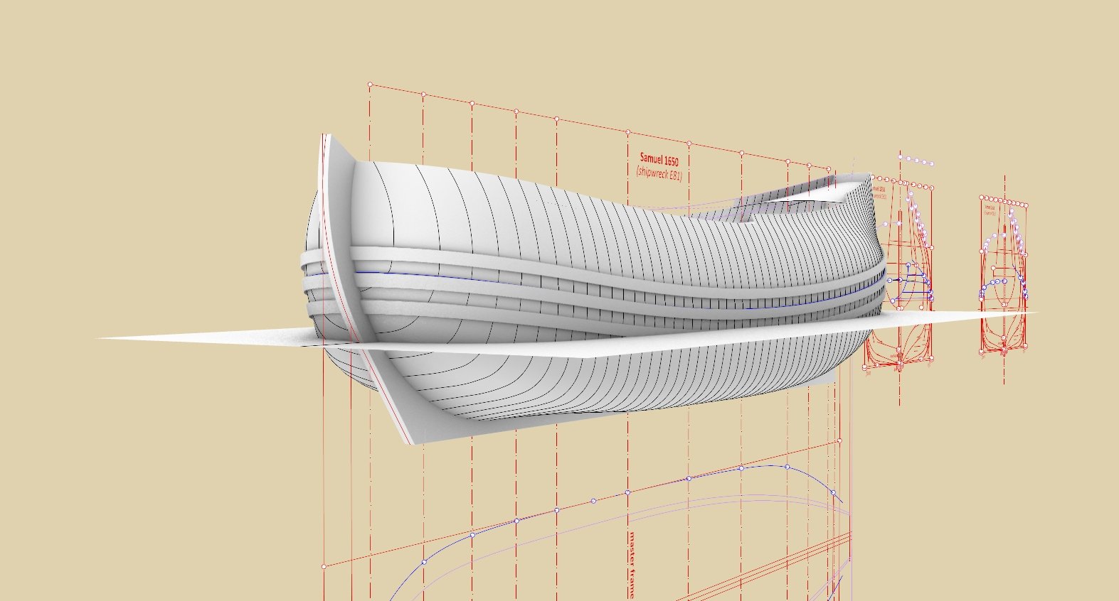
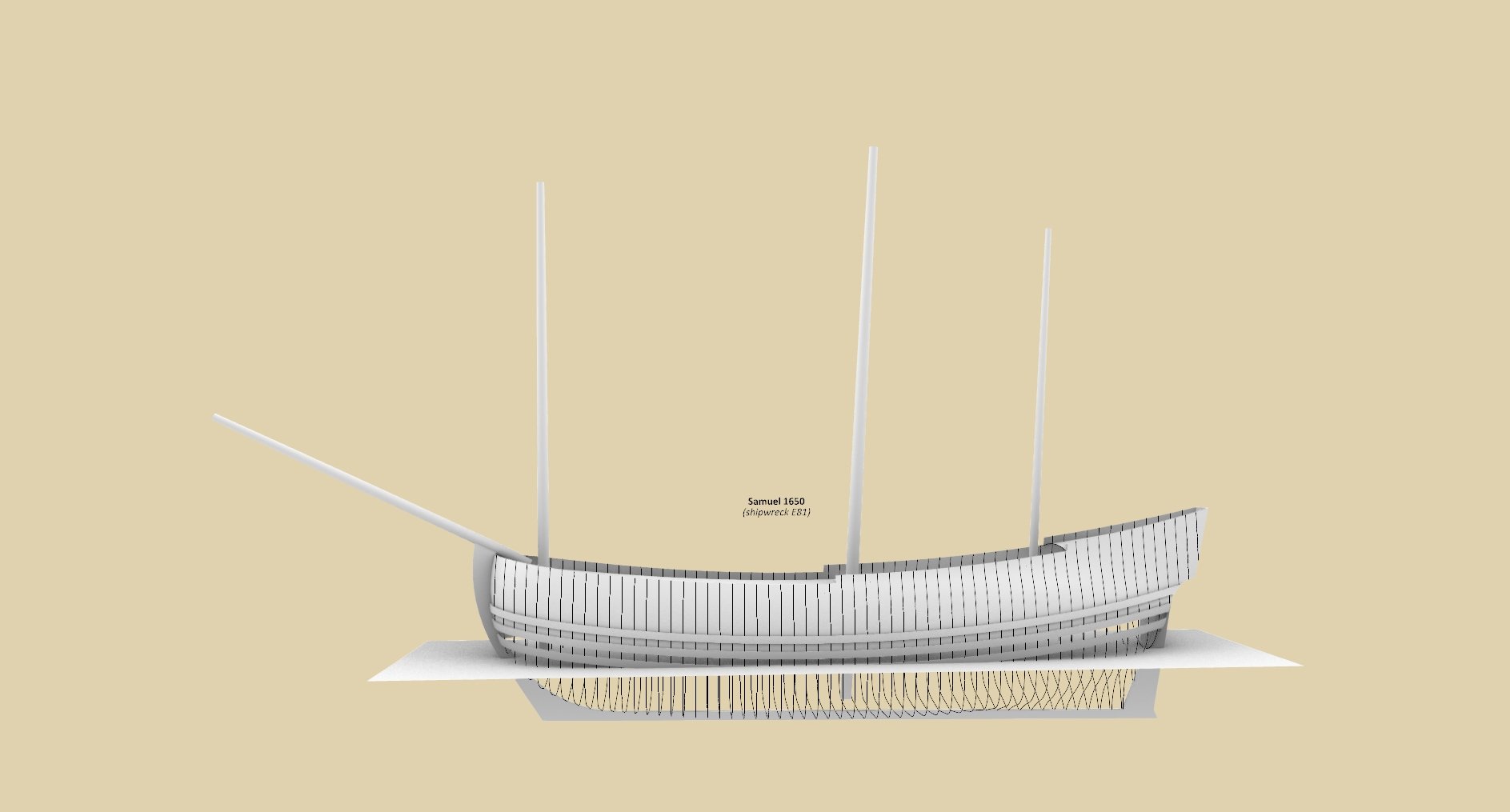
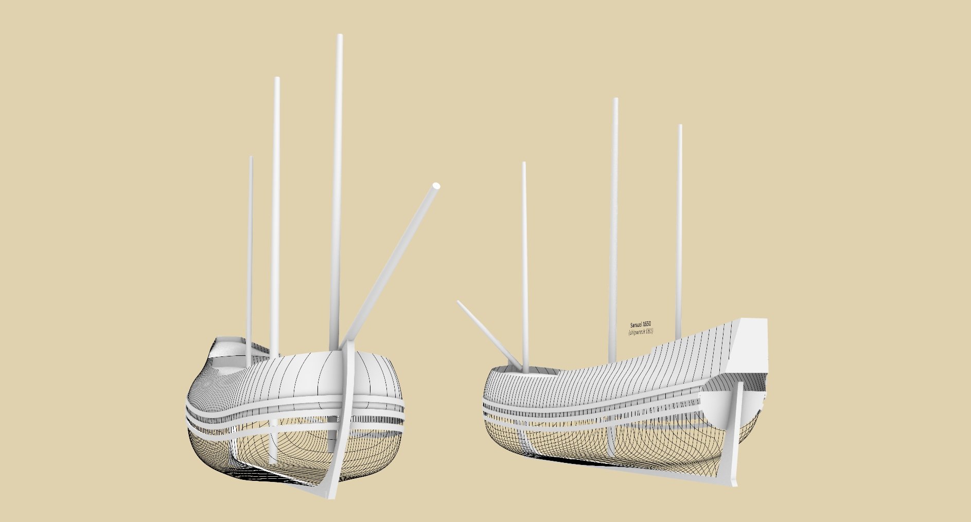
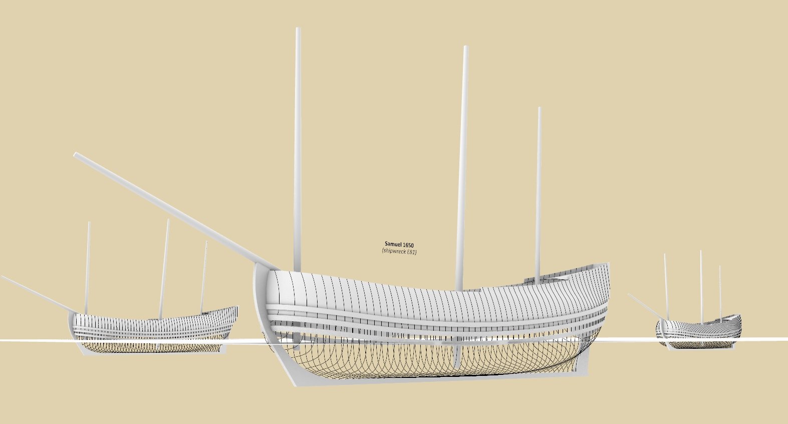
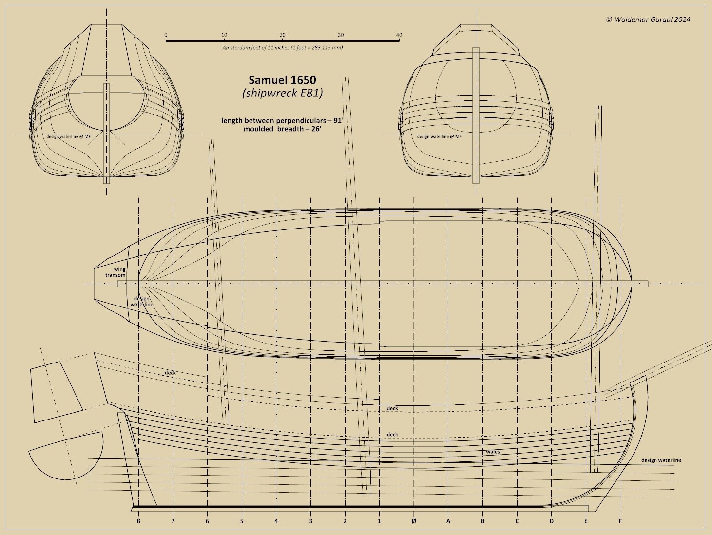
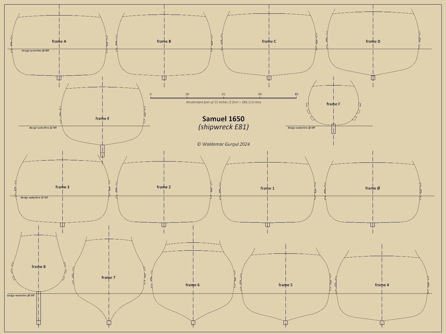
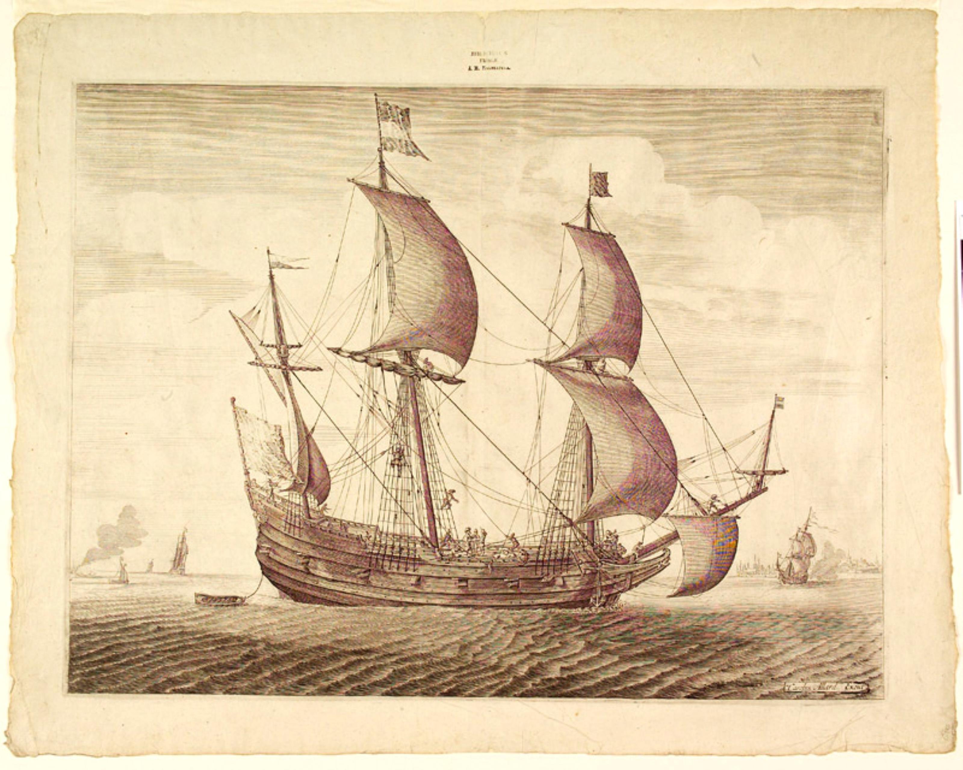
This thread will show the result of a conceptual interpretation and a partial reconstruction attempt of an important, very well-preserved wreck of a mid-17th century Dutch cargo ship, excavated in the Ijsselmeer basin in the north of the Netherlands. The ship has been identified as the Samuel, serving the trade with the Iberian peninsula, among others. A very extensive archaeological record of the shipwreck can be found at: https://beeldbank.cultureelerfgoed.nl/rce-mediabank/?mode=gallery&view=horizontal&q=e81&page=1&record=bb0c9df7-b54d-2770-7cff-2d946e245039&sort=order_s_objectnummer%20asc Shipwreck E81 (Samuel 1650), photo by Jan Rypma Ship’s main dimensions (as recorded, read or interpreted): Breadth: 26 feet Length of keel: 78 feet (3 x breadth) Length between posts: 91 feet (3.5 x breadth) Depth in hold: 10 feet * * * Keel assembly, lengthwise division & main design lines Ratio of sternpost rake to stempost rake: 1:6 (note: stempost rake measured from the point where the rabbet line crosses the upper edge of the keel and enters the stempost) Height of sternpost: ~2 x height of tuck (note: height of tuck at the waterline level) Height of stempost: height of sternpost + 1 foot Longitudinal position of master frame: 1/3 of keel length (see diagram for the determination method) Note: the radius of the stempost in the diagram relates to the arc of the upper rabbet line. According to the archaeological record, the following relationships and design sequence of Samuel 1650 have been found or guessed: – the waterline level was set at eight feet, corresponding to the height of tuck (or vice versa), horizontally (as in the diagram) or, alternatively, angled to the lesser height of 7 feet at the bow, – the length of the waterline (not including the posts) has been divided into seven parts (with a possible subdivision of 14), – the line of the floor was set, terminating aft at the height of tuck and, at the fore, one foot below the horizontal waterline level (or at the intersection of the design waterline with the stempost for angled waterline); at the master frame deadrise has been fixed at three inches, – the height of the greatest breadth at the master frame is 1/10 of the total length of the hull (i.e. between posts), about one foot above the design waterline, – the wales are perfectly parallel to the line of greatest breadth (scheerstrook, scheergang). Of note is the extensive use of logarithmic curves to define the shapes of the main design lines. These are one of the easiest types of curves (or maybe better: transformation) to use in practice, especially as they are ideally suited to achieving the contours of the frames straight away on the mould loft with a trivial simplicity, and without any real need to make any scale drawings on paper in advance. Essentially, no knowledge of theory is required, just familiarity with straightforward division operations is enough. So much for the essentials of this rather simple design (in conceptual terms). * * * Cross-sections Dimensions of master frame components (as recorded, read or interpreted): Width of the „flat”: ~17 1/3 (2/3 x max. breadth) Deadrise (at the master frame): 3 inches Design depth: ~9 feet (1/10 x length) Futtock sweep: variable radius (equal to respective breadth) or fixed radius (equal to max. breadth); note: both variants result in almost indiscernible shapes for this shipwreck, Bilge sweep: 4 1/3 (fixed radius; 1/6 x max. breadth) Reconciling sweep: 17 1/3 (fixed radius; 2/3 x max. breadth) It can also be added that the transverse contours of the „flat” for all leading frames are straight lines, except for the last leading frame it is in the form of an circular arc (note: on the diagram below one more frame was drawn between the last leading frame and the sternpost). Employment of the arc is for the smooth transition of the hull surfaces toward the sternpost, providing better waterflow for at least acceptable rudder efficiency. * * * Possible appearance The graphic below shows a hypothetical appearance of the Samuel 1650 once its upperworks have been recreated. The Samuel 1650 is actually almost the smallest ship for which the two-deck configuration was used. The distance between decks was taken from Grebber's table, reproduced in both Witsen's 1671 and van Yk's 1697 works. This feature, taken together with the relatively small size of the ship, make Samuel's silhouette quite tall, and despite the smallest distance adopted between these decks (about 4½ feet). The very full shape of the underwater part of the hull, suitable for a cargo ship, is also evident. Taken together with the high freeboard, this must have made the ship very leeward, which ultimately surely contributed to her disaster, but also preserved her to our times. The position of the masts, or rather the foremast and mainmast, was taken from the shipwreck documentation, but it must be said that it is altogether quite typical: the mainmast at the middle of the keel and the foremast above the gripe, i.e. above the junction of the keel with the stem post. Also below are some graphics showing ships of a similar nature. While not all from the Samuel's particular period, especially the last two, they still can be relevant for various details, but also to get a better feel for this vessel’s general specifics (Dutch archives). * * * Reconstruction hull lines As the below drawings are reconstruction plans, there is no need to take them too literally. For example, a 'perforated' railing may be added in the aft part to make the sheer of the ship more attractive, or the upper edge of the stern 'mirror' may be made as an arc. Some more wales with a smaller cross section above the three main ones drawn on the plan should actually be attached as well, and the sternpost possibly shortened a little, roughly to the height of the wing transom, for free entry of the tiller into the hull, etc. The correct arrangement of the garboard strakes in Dutch convention is well shown below in the documentation of the Samuel 1650 shipwreck. Actually, in the central part of the hull, the garboard strakes are not in contact with the frame timbers at all. On the plans the garboard strakes are not drawn because these plans show the contours of the frames and not the planking. On the sheer view, however, both rabbet lines are plotted, just for this purpose. The hull lines has been checked for fairness (as opposed to actually forming the shapes) with diagonals and waterlines. Thank you for your attention, Waldemar Gurgul


.thumb.jpg.7295356b3a5078bb888a3960870f4bd8.jpg)

.thumb.jpg.79af1756cc0510df4dc806e6bad5a948.jpg)
.thumb.jpg.277518e196f0e94098a80a4213f12952.jpg)

-
- 13
-

-

-
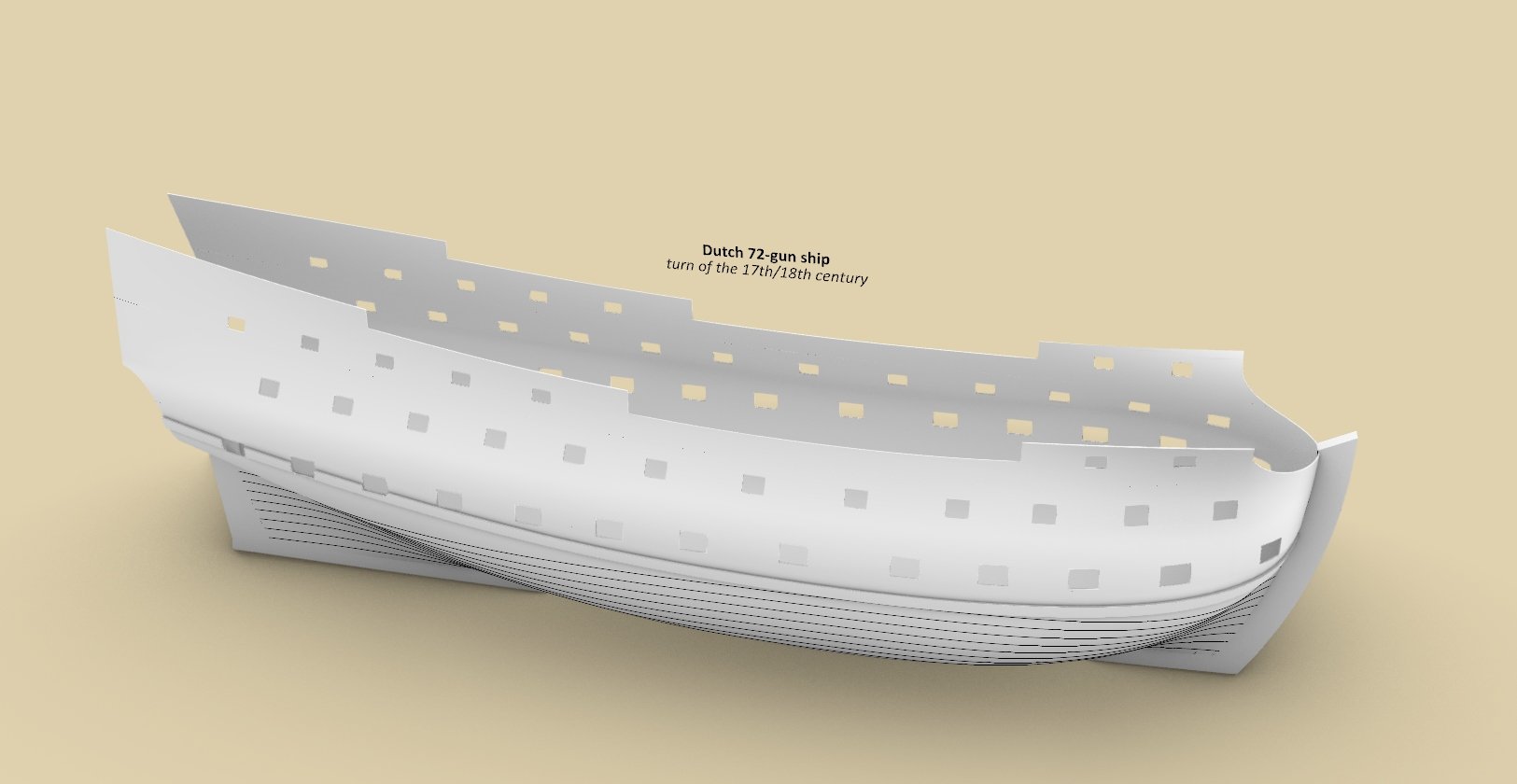
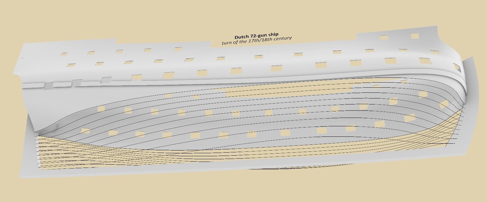
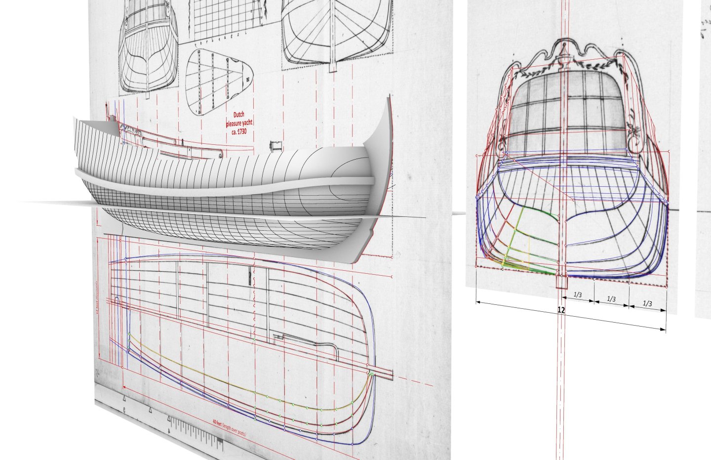
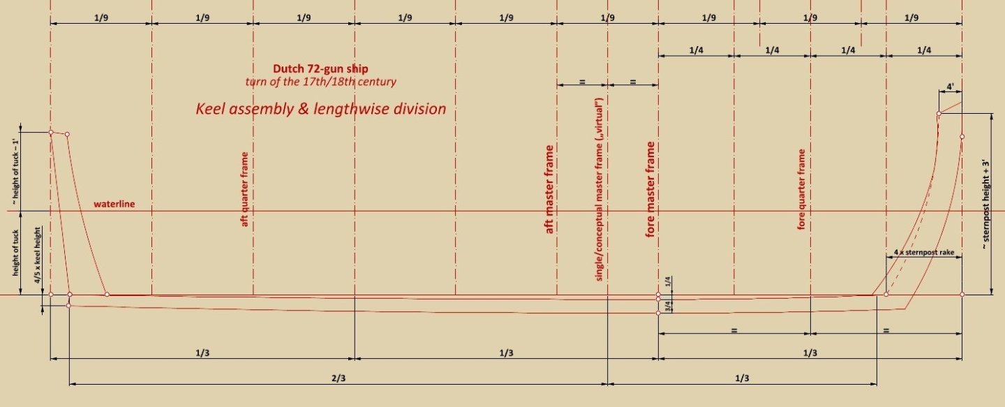
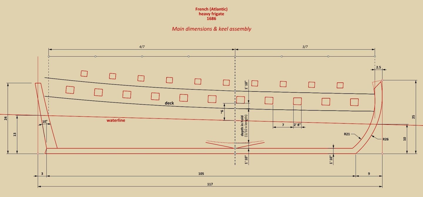
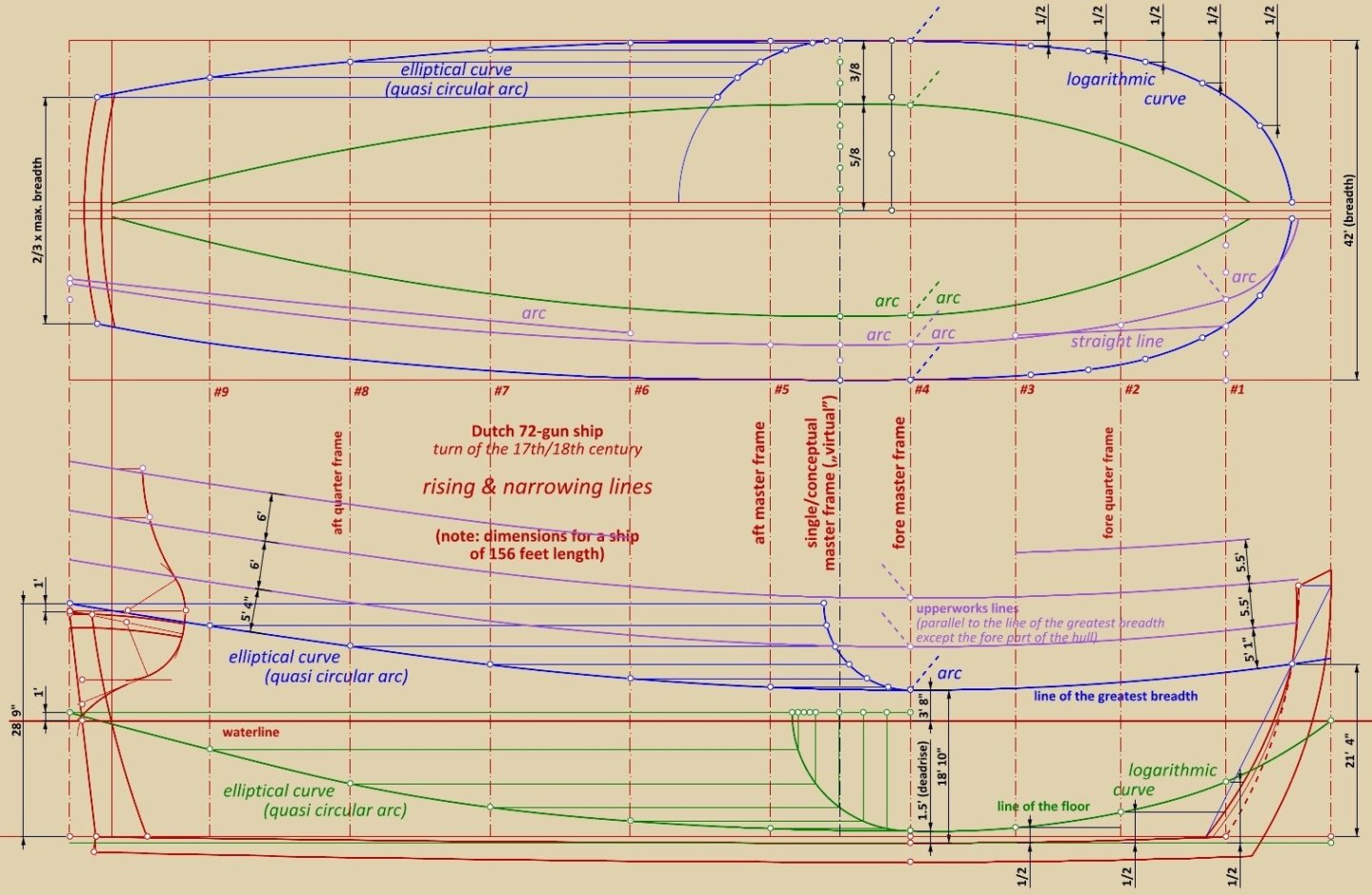
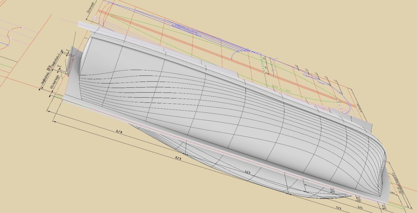
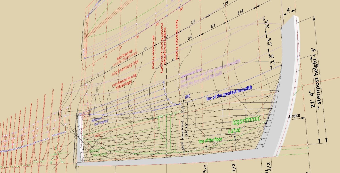
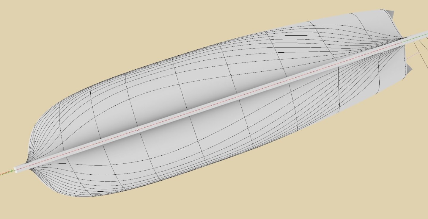
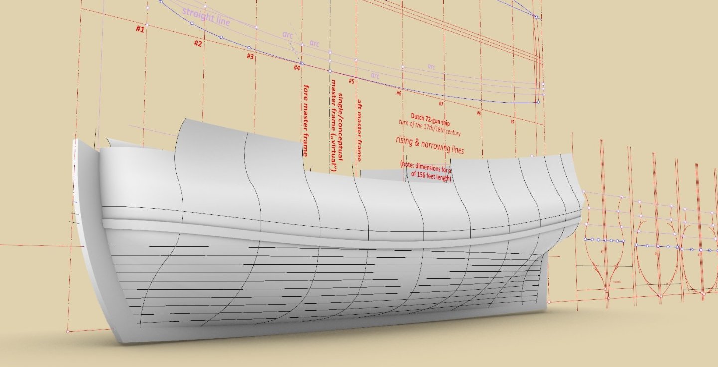
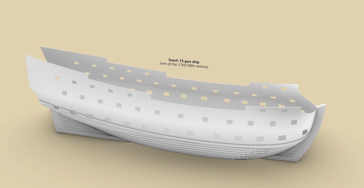
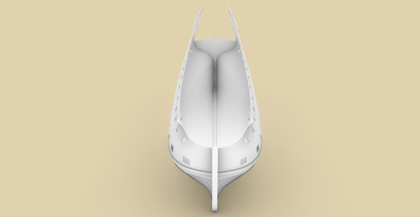
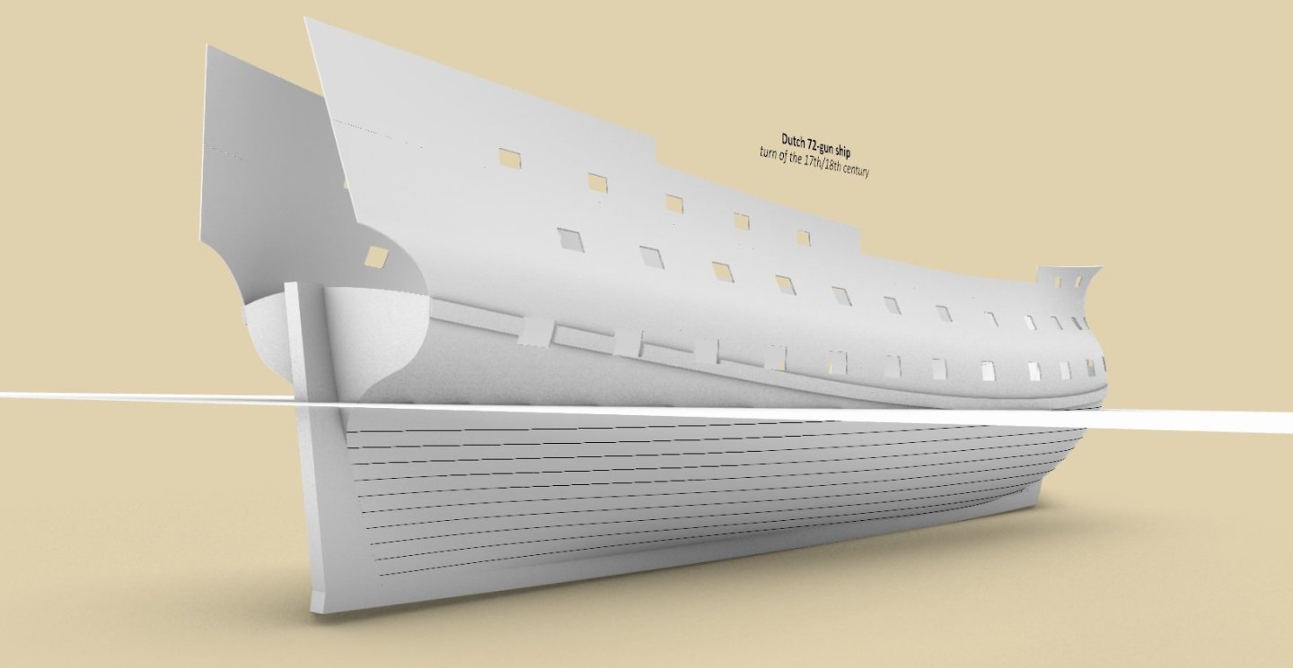
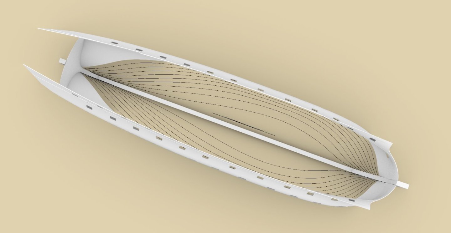
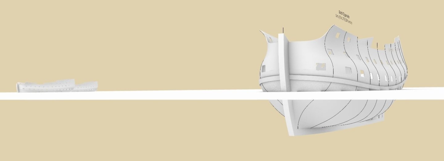
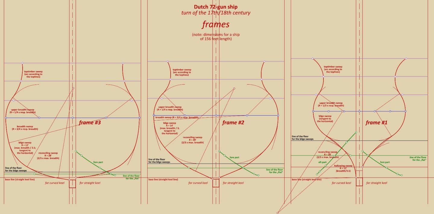
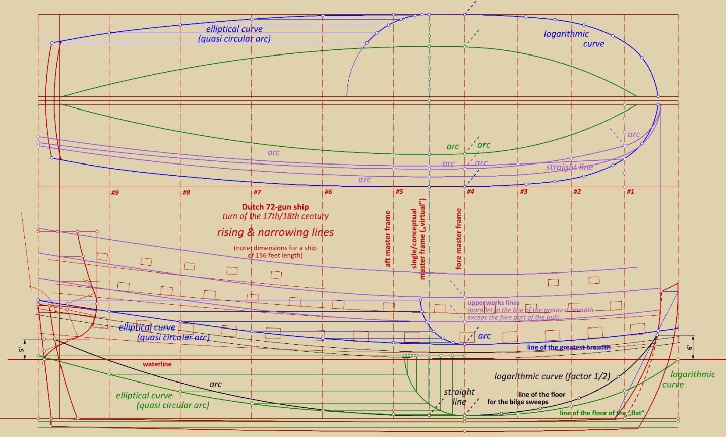
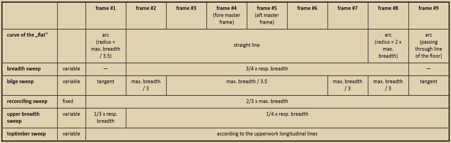
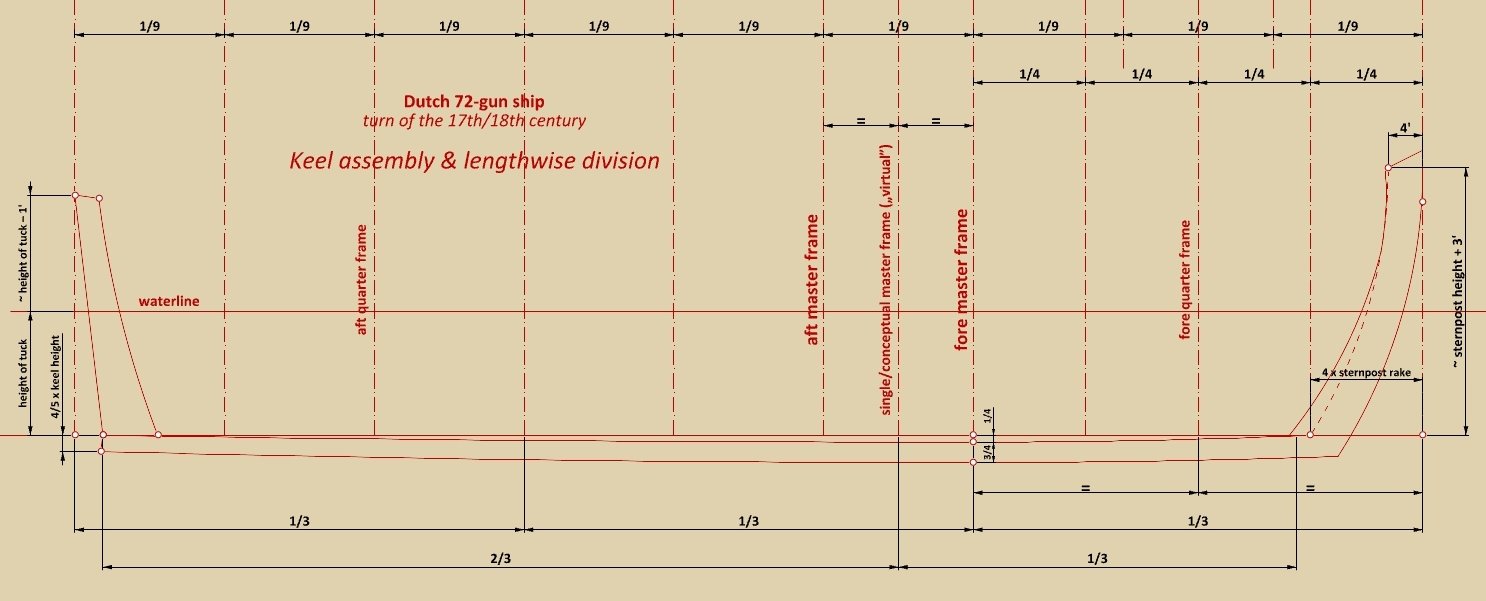
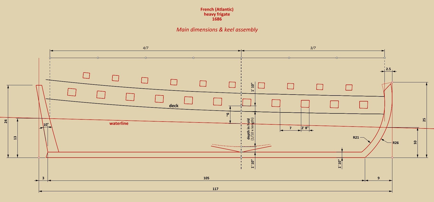
It should be clarified at once that this plan, tentatively dated by me to the end of the 17th century, is one of the last of the era before the widespread adoption of design diagonals, which in the Netherlands occurred in the third decade of the 18th century at the latest (see as to this Ab Hoving & Alan Lemmers, In Tekening Gebracht. De achttiende-eeuwse scheepsbouwers en hun ontwerpmethoden, 2001). In historical terms, this is the period of the Third Anglo-Dutch War (1672–1674), the War of the League of Augsburg (1688–1697) and the War of the Spanish Succession (1701–1714). As it seems, this very plan was not previously widely known and was kindly provided to me for examination, in terms of the design method used, by Ab Hoving. This is an exceptionally fortunate circumstance for several reasons, and I am most pleased that it demonstrates classical prediagonal design methods in their latest, most advanced form and for the most demanding projects, that is of a dedicated warships. It is apparent at first glance that conceptually this is a more sophisticated design compared to the civilian designs presented so far (Samuel 1650, Witsen’s pinas 1671, Rålamb's boyer & fluit 1691), while it is more similar in this sense to the Dutch capital ship ca. 1665 (Hohenzollern model), the French (Atlantic) heavy frigate design by Chaillé 1686 and the designs of 1679 by Hubacs of Dutch origin, boasting dozens of designed and built ships to their credit. * * * The primary aim of the project will not even be to search for all the (main) proportions of the design parameters, as many of them were quite arbitrary (as they still are today), but rather to search for more universal procedures applied for shaping the body of the hull, quite independent of these proportions. The plan (Archives of the Nederlandsche Marine): The drawing is originally captioned: Frigate ship long between posts 165 feet for 72 guns [seen] from inside. Contrary to this caption, this is a design for a ship 156 feet long, not 165 feet, as indicated by the size of linear scale (30 feet long; a foot divided into 11 inches), and according to the metric scale added nowadays, the plan was drawn at a scale of 1 inch = 5 feet 7 inches, or 1:62. At this scale, the drawn ship measures 156 x 42 x 15 feet (length x breadth x depth in hold), which corresponds fairly well to the dimensions of almost the entire, long series of 28 2nd rate ships built under the 1685 programme. As one would expect from a dedicated warship, the hull has quite a sharp entry, as well as overall shape compared to merchantmen designs. In design practice, this is achieved primarily by increasing the height of the deadrise, or in other words, the line of the floor. According to the design method and customs, only the leading (conceptual) frames are pre-designed. The shape of the remaining, filling frames, could be or had to be (especially at both extremities of the hull) determined according to the ribbands, already installed during the actual construction. However, not to rule out any possibility, it is also possible that the drawn linear scale is out of sync with the rest of the drawing and, in addition, slightly longer than it should be, and that the ship length of 165 feet, given in the caption, is correct. In that case, the scale of the drawing would be 1:66 and the hull breadth would be 44 1/2 feet (giving in this way, for example, the dimensions of Gouda 1719, built in Amsterdam by van Reenen). This does not really change the essence of the project (recognition of the design method), and in the context of the dating and design practices of the time, it may be indicative of the repeated use of the same designs to build ships of different sizes. To put it another way, the plan may have been drawn at a scale of about 1:62 as for a 156-foot ship, and after the scale change, it became the design for a 165-foot ship. Keel assembly & longitudinal division Note: some of the dimensions below are actually redundant, but have nevertheless been left on the diagram for better readability. * * * The keel has been drawn quite realistically – on the plan it has a deflection with the greatest value at the forward master frame, amounting to 1/3 of the keel height, and is tapered towards the stern to 4/5 of the total height. The stempost rake is very small, being only 4 x sternpost rake (measured to the supposed rabbet line). As late as 1737, the French shipwright-designer Blaise Ollivier reported that on Dutch ships it was usually larger, 6 x sternpost rake. To determine the position of the leading (conceptual) frames, the ship was divided into nine equal parts. For the fore part of the ship an additional division of four parts has been set up. The contours of the 'virtual' single master frame are not even defined on the body plan, nevertheless the position of this frame is essential in this design to establish the nominal (largest) values of all narrowing lines (breadths/widths) on the plan view. To put it another way, it is this actually unbuilt in real construction, single 'virtual' master frame that is widest at all levels – at the 'flat' level, at the level of the line of greatest breadth and at the level of the toplines that define the upperworks. Its lengthwise placement have been chosen in such a way that it falls at 1/3 of the keel length. For the construction of the physical ship in real scale, two 'twin' master frames were defined. The fore master frame falls at 1/3 of the length of the entire hull, and the aft master frame at an equal distance from the single 'virtual' master frame (see diagram). By design, the contours of these twin master frames are not quite identical, the largest difference being about 1/4 foot, nevertheless similar enough that in carpentry shipbuilding practice they could be treated as identical without much detriment to the quality of the end result in terms of its conformity with the design. The diagram also indicates the likely placement of the two quarter frames. From these positions, going towards both extremities of the hull, the contours of the frames already have a different geometric structure compared to the central frames between these quarter frames. Main design lines (rising & narrowing curves) It must be said at the outset that the shape of all the elliptical lines in this design, obtained by means of the popular geometrical transformation called mezzaluna, and employed in its numerous variations, is so closely coincident with the ideal shape of the arc of a circle that it is almost certain that the use of these elliptical curves was merely the result of the designer's lack of a compass of sufficiently huge size, rather than a deliberate effort to obtain some particular curvature different from the ideal circular arc. In drawing practice, it was in this way that a number of points lying on the desired curve were determined, and these points were then connected using drawing instruments – either templates of fixed curvature or battens of variable curvature adjustable by a screw or string. * * * Line of the floor (green) This is essentially the most important design line for any ship of the period. At the main frame, the deadrise is large, appropriate for warships, 1.5 feet measured from a realistically curved keel, giving an inclination of 1:8.75 in relation to half the floor width. The total width of the floor almost matches the 'standard' value of 2/3 of the hull breadth, and in this particular case is 5/8 of the breadth. At the stern, the line of the floor terminates normally at the height of tuck (where the fashion pieces join the sternpost), At the bow, at the intersection with the rabbet line, the height of this line is not great, however, the sharp gripe is still obtained by the specific way in which the bow frames are formed, different from the central frames. In the vertical plane (sheer view), the lowest point of the floor line is at the fore master frame, while in the horizontal plane (plan view), the greatest width of this line falls already in a different place – at the single "virtual" master frame. The section between the single "virtual" master frame and the fore master frame is a mirror image of the corresponding section of this line from the aft side. Both observations also apply to all other design lines. After examining several cases from the era, I can probably say that the curvature type of the line of the floor is very characteristic of Dutch designs, i.e. a logarithmic curve for the fore part of the hull and a (supposed) circular arc for the aft part. Line of the greatest breadth (blue) Apart from the (quite accurate) approximation of this line to the arc of a circle using a mezzaluna, this line does not differ in any way from the standard in terms of the way it is drawn. However, it is possible to point out the relatively quite significant height of this line at the master frame (almost 4 feet), with the effect of increasing the transverse stiffness of the ship and thus enabling the lowering of the gun ports (and therefore the rest of the above-water part of the hull for better weatherliness), and also the noticeably sharper shapes of this line at the bow (in top view) compared to merchantmen, for greater speed. Lines relating to the upperworks (violet) The same concern for improving weatherliness by lowering the height of the upperworks is also visible in the case of the toplines – at the fore part of the ship they are lowered by about half a foot compared to the aft part of the hull. In the top view, the designer partially spoiled these lines (or just ignored some of them while drawing the frame contours), especially in the stern part, which is not surprising considering that these were the least important elements of the design. As a consequence, their run in the top view on the below diagram was partially corrected based on the frame contours. Also, in these circumstances, the lowest of the three toplines is not necessary at all to define the shapes of the upperworks (and even harmful), because the designer, when drawing the frame contours, used a different method to determine the radii of the upper breadth sweeps anyway, i.e. based on the respective frame widths. Perfect shapes in the sense of geometric smoothness. And without any correction with diagonals and waterlines whatsoever! Just the correct formation of the frames. Yet, there is something else incomparably more important, about which later. Now, just that this plan is a real, unique gem with probably no equivalent, because it shows the true, advanced engineering face of Dutch shipbuilding of the Ruyter era, and hitherto hidden behind the façade of Witsen's and van Yk's essentially carpentry-oriented works, both touching hardly on conceptual design issues, unlike, for example, their English contemporaries in the field. Before continuing properly, a bit of fun with the renderings. I am constantly amazed at how perfectly smooth the hull lines have been achieved by the designer through the skilful selection of the individual sweeps radii for all the consecutive frames. Gun ports are not evenly spaced, most likely for structural reasons (knees, beams, hatches etc.). In some of the renders, the ship has been trimmed four feet aft. Well, now there's bound to be a Nobel Prize 🙂. It was enough to look at something else than the works of Witsen and van Yk themselves (these, although unrivalled in structural and carpentry aspects, are nevertheless extremely poor in terms of design methods). It was also enough to finally break with the uncritical endorsement of modern studies by academic fellowship, displaying a notorious tendency to conformistically rewrite increasingly inadequate and anachronistic theses from each other's 'official' publications, and to look directly at the sources without such mediation. But to the point. Analysing the shapes of the frames on this plan, I finally uncovered that not one but two lines of the floor were used in this design, nevertheless, for some reason, the second one was not drawn at all on the sheer view (or was later erased). This undrawn/erased line of the floor (in black on the diagram) was used for fixing the lower edges of bilge sweeps. In contrast, the one left on the original drawing (green in the diagram) shapes the bottom of the hull and also materialises the edge of the 'flat', as the ship was intended to be built using the bottom-first method. They have both the same deadrise at the fore master frame. Among other source indications, this plan is one of the most important pieces of evidence that the leading frames (could) have been pre-designed in their entirety also in this very method (i.e. bottom-first), especially for more complex warship designs. Both of these lines are used in a different way to their counterparts in the Mediterranean/English tradition. The way in which the contours of the frames are formed is shown in the graphic below. Apart from the frames at the hulls's extremities, i.e. #1 and #9, the order is as follows: – first a line of the „flat” connecting the keel to a point on the line of the floor of the "flat" (green colour), – then a futtock sweep with a radius of 3/4 x the respective frame breadth, – then a bilge sweep tangent to the futtock sweep and tangent to the level of the second line of the floor (black colour), – then a reconciling sweep with a fixed radius of 2/3 x max. breath, joining the bilge sweep and the line of the „flat”, tangentially on both sides, – finally an upper breadth sweep with a radius of 1/4 x resp. frame breadth and a toptimber sweep in accordance with the longitudinal lines defining the upperworks (violet). For all frames, the individual sweeps have the following parameters: Thank you for your attention, Waldemar Gurgul


-
- 12
-
-


.jpg.6afa2457e6ed358a5047f29e57cc3339.jpg)
.jpg.4cfe4227eae873bea996a1aa4e7fad68.jpg)
.jpg.aab6aaca50c6d54e89fbc654641494f5.jpg)