.jpg.6c90d67e7e9071af590f4d4a2a8bc908.jpg)
Waldemar
-
Posts
1,003 -
Joined
Content Type
Profiles
Forums
Gallery
Events
Everything posted by Waldemar
-
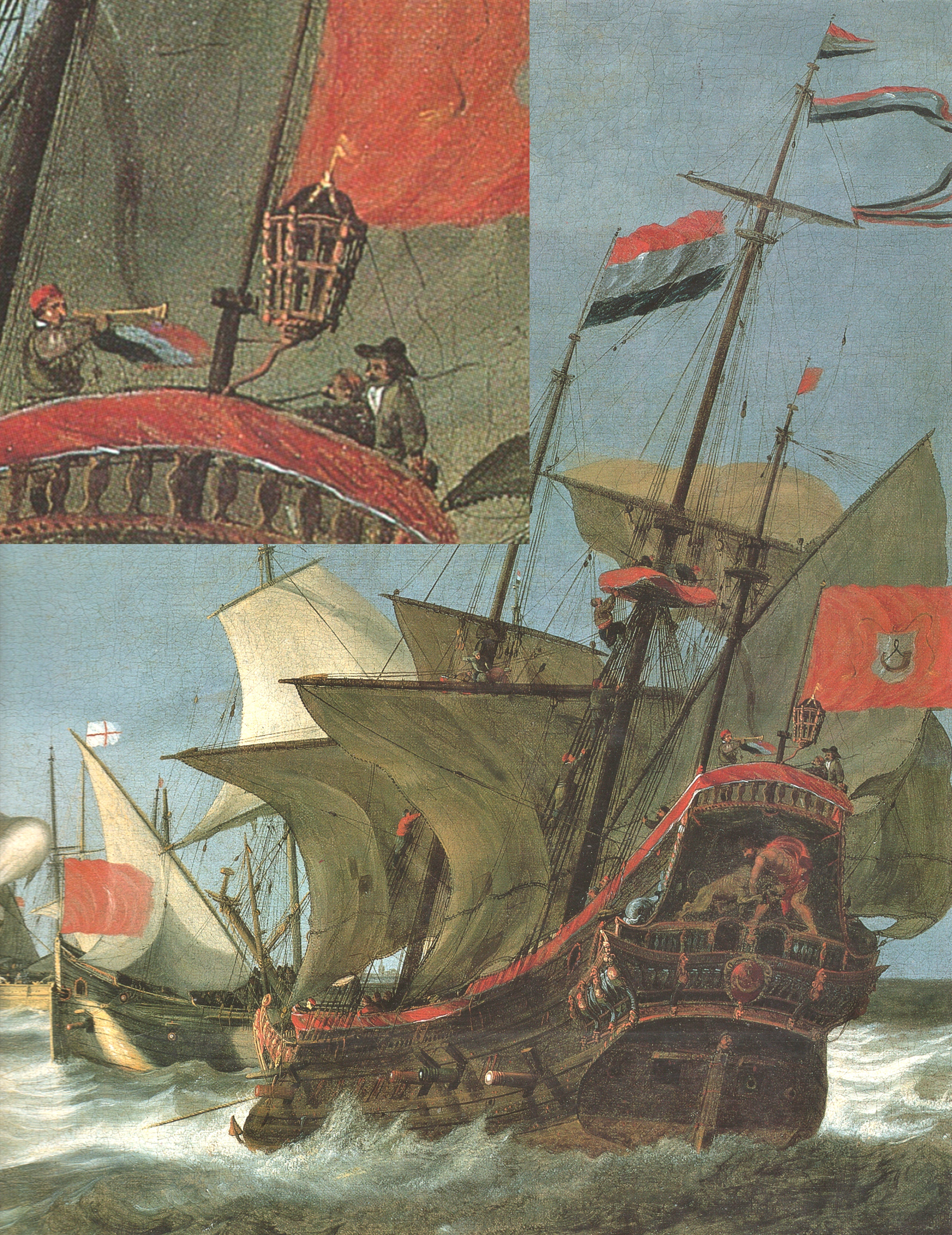
.thumb.jpg.c6343966b029e7941df5b987d129aac6.jpg) Hi Olli. A relevant fragment of nearly contemporary painting I have quickly found (A View of the Hoorn with the Ships 'Hercules' and 'Eenhorn' by Bonaventura Peeters the Elder, 1634):
Hi Olli. A relevant fragment of nearly contemporary painting I have quickly found (A View of the Hoorn with the Ships 'Hercules' and 'Eenhorn' by Bonaventura Peeters the Elder, 1634):
-
Iberian (Basque) Atlantic Whaler ca. 1550 — as, dos, tres…
Waldemar replied to Waldemar's topic in Nautical/Naval History
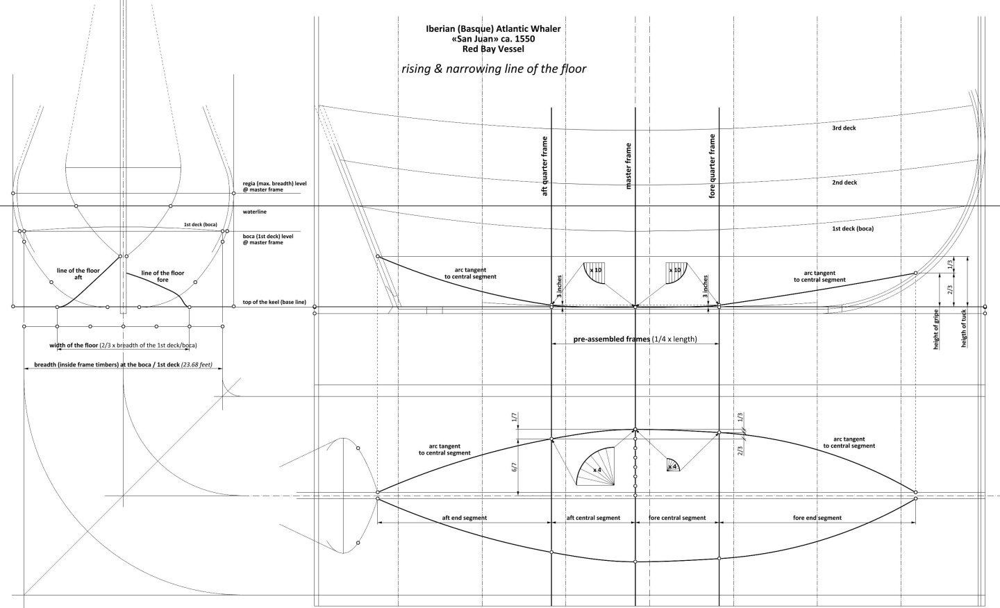
Line of the floor (refers to diagram above) This is the most important design line determining the character and properties of the vessel. In a manner very characteristic of the Mediterranean method, it consists of four geometrical segments, that is, two central and two end segments, including the three conceptual frames separating these segments (see diagram). This particular configuration is a relic and is closely related to the non-graphic moulding of the shape of the frames (that is, without drawing them on paper beforehand), immediately traced to actual scale on the mould loft. The run of the central segments of this line, or more precisely the co-ordinates for the central frames, i.e. between the quarter frames, were the result of the use of the geometrical devices also shown in the diagram. For the shaping of the remaining frames, at both ends of the hull, the use on the mould loft of these geometrical devices (normally any of the numerous variants and sub-variants of the mezzaluna) was no longer possible, because these end segments were no longer tangent to the horizontal keel line, as is the case for the two central segments. This particular inconvenience eventually led to the introduction of more and more complete plans drawn on paper, incorporating more and more design elements, such as the longitudinal design lines in their entirety, as well as 'all' frame contours. Nevertheless, until then, the role of the end segments of the longitudinal design lines, which were the guides for the erected frame timbers, was fulfilled by wooden battens or ribbands, yet this was only at the stage of the actual construction of the vessel. These physical ribbands had to be tangent to the elliptical lines thus extended from the central segments (of the mezzaluna type), and in addition, by natural bending, they were given the shape of circular arcs or curves very close to them. As a result, they can also be approximated quite well in this way on the reconstruction plan. Apart from the above, the division of the longitudinal design lines into a larger number of geometrically simple segments (in this case four), gave more freedom or flexibility in shaping the run of the entire design line, actually even necessary for the correct implementation of the design intent. * * * In a rather surprising way, almost the entire length of the two central segments is below the top edge of the keel. This was arranged so that a longitudinal concavity with a profile corresponding to these segments, about two inches deep, was cut into the upper surface of the keel along this length. This procedure meant that for the central frames fitted into this concavity it was not necessary to add hollowing/bottom curves, as was already necessary for all the other frames, i.e. with the individual deadrise more or less distant from the keel. * * * The width of the line of the floor (at the master frame) is very large. It amounts to as much as 2/3 of the width of the base design deck (boca), well beyond the range categorically recommended, for example, by Fernando Oliveira (ca. 1570–1580), that is, of 1/3 to 1/2 (alternatively, the width of the line of the floor in the San Juan can also be equal to 3/5 of the maximum breadth of the hull, which gives practically the same value as 2/3 of the width of the boca). In doing so, Oliveira specifies that different values in this range are appropriate for different types of ship. On the other hand, the author of the so-called Salisbury Manuscript (ca. 1620–1625) is content merely to state that the optimum width of the line of the floor is half the breadth of the hull, without further explanation. It is this large width of the line of the floor that makes the San Juan have such an unusually sharp entry and run, especially in the lowest parts of the hull. Reducing this width would result in increasingly full hull ends (with the same shape of the transformed base master frame). -
Iberian (Basque) Atlantic Whaler ca. 1550 — as, dos, tres…
Waldemar replied to Waldemar's topic in Nautical/Naval History
-
Iberian (Basque) Atlantic Whaler ca. 1550 — as, dos, tres…
Waldemar replied to Waldemar's topic in Nautical/Naval History
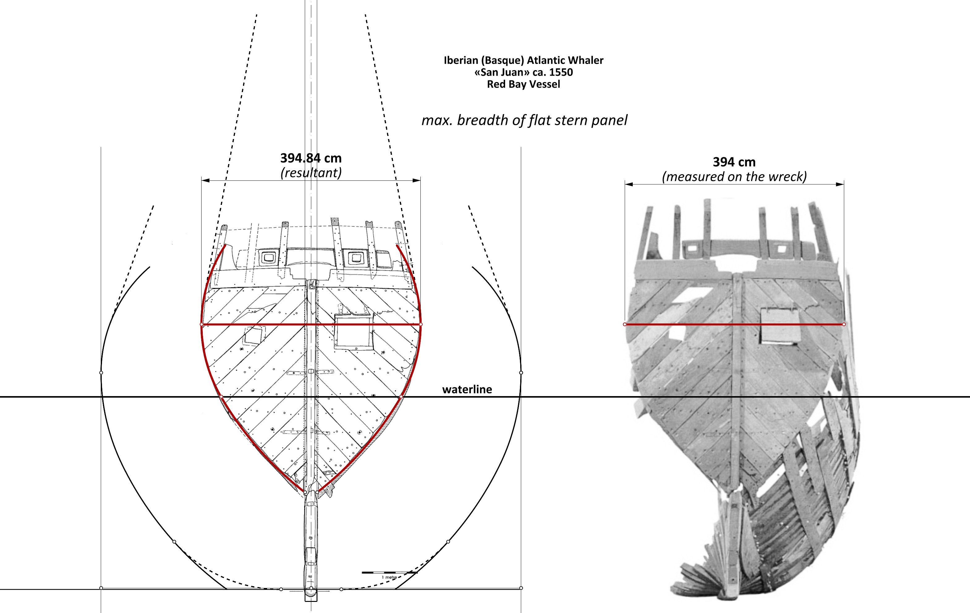
A very good test of the validity of the readings and findings of the design method employed, and presented so far, including both the specific proportions and the absolute dimensions applied in the design of San Juan, is to compare the values of the two largest breadths of flat stern panel: the first measured in the actual wreck and the second obtained in the manner shown above. The point is that, firstly, this particular dimension could have been precisely measured on a very well-preserved, undeformed fragment of the shipwreck's stern, so the measurement effected under these conditions is the most authoritative for comparisons, and secondly, it is at the same time a resultant dimension, in one way or another dependent on virtually all other proportions, linear dimensions or radius values found and shown so far. To put it differently, any change in even one of these design parameters, whether relative or absolute, would inevitably have an impact on the breadth of the stern panel ultimately resulting from the reconstruction carried out. This verification falls favourably: the monograph gives a measured value of 394 cm for this dimension, while the reconstruction of the ship’s design presented above results in a value of 394.8 cm (for the cubit length of 0.5746 m given in the monograph). Or, four millimetres per side, which is virtually nothing for such relatively large sizes, and well within both the manufacturing and archaeological/measuring tolerances. This is also shown in the diagram below (including drawing and photo from the monograph).
-
Iberian (Basque) Atlantic Whaler ca. 1550 — as, dos, tres…
Waldemar replied to Waldemar's topic in Nautical/Naval History
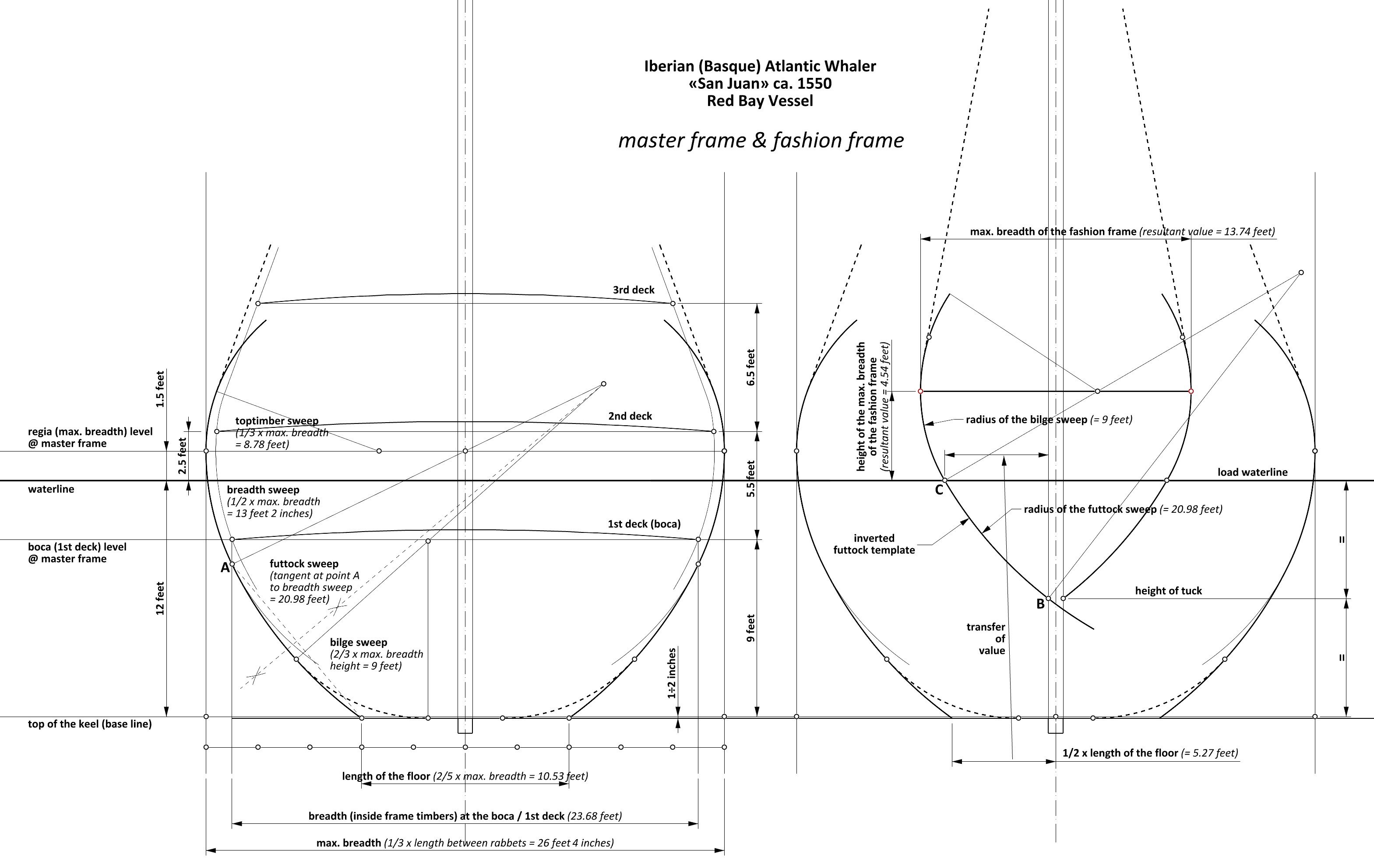
Master frame The formation of the master frame shapes at this stage of design is primarily necessary to make a (single) set of wooden templates, used in turn to cut the actual frame timbers, and this for almost the entire length of the hull. This second process, of a non-graphical nature, is perhaps best described in the earliest English shipbuilding manuals of the first decades of the 17th century — the so-called Salisbury manuscript ca. 1620–1625 and the so-called Newton manuscript of the second quarter of the century, which describe still essentially Mediterranean methods, employing a single set of wooden templates, featuring fixed radii of the individual sweeps groups, to obtain the shapes of most of the frames needed. The following sequence of master frame design for the San Juan is proposed: — the breadth of the master frame (inside the planking) was set at exactly 1/3 of the hull length between the rabbets (39 1/2 cubits x 1/3 = 13 1/6 cubits, or 26 1/3 feet), — the heights of the various design elements, such as the height of the maximum breadth of the hull and the maximum draught, depend directly on the predetermined heights of the decks, and so: the draught level was set at 2.5 feet below the second deck, and the height of the maximum breadth at one and a half feet above the draught line (the latter figure is very important for the hydrostatic properties of the ships, and more specifically their lateral stability). Also, by the way, if this had been a warship or at least an armed one, this would have resulted in about four and half feet of gun port height above the water, — sweeps: first a breadth sweep was drawn with a radius equal to half the maximum breadth of the hull, then a vertical line was drawn from the intersection of the boca line (1st deck) with the inner edge of the frame timbers (inner because the deck is inside the frame timbers), the intersection of this line with the breadth sweep giving point A (see diagram); in passing, it may also be added that it was the breadth at the level of the boca that was often given as the principal or only breadth of the ships in this period and in this method. Thus, the breadth of the San Juan would have been given in the sources as 23 feet 8 inches or (nearly) 12 cubits, the futtock sweep was then traced, tangent at point A to the breadth sweep and running to a point on the base line located at a distance of 2/5 from the axis of symmetry (see diagram); the radius of this sweep is not predetermined and is consequential (the diagram also shows with dashed lines an easy and well known way to find the centre of this sweep), next, a ‘softening’ bilge sweep was added with a radius equal to 2/3 of the height of the maximum breadth (13.5 feet x 2/3 = 9 feet); in addition to just softening the contour of the frames, this sweep is also of fundamental conceptual importance, as it is used for subsequent master frame transformations to obtain all the other predefined frames, finally, a toptimber sweep with a radius smaller than the breadth sweep, i.e. equal to 1/3 of the maximum breadth, has been added. The radii of the individual sweeps have been selected so that their proportions relative to each other ensure the correct shape of the hull along almost its entire length. For example, the reduction of the toptimber sweep radius in relation to the breadth sweep radius avoids the formation of upperworks that are too voluminous and too high, which becomes particularly obvious with the later transformations of the main frame, i.e. approaching the ends of the hull. Fashion frame According to the advice or insights of authors of the period, such as João Baptista Lavanha or Manoel Fernandes, the contour of the fashion frame of the San Juan was indeed created using an inverted futtock template obtained from the previously defined shape of the master frame. It has to be said that, on the one hand, the position and size of the fashion frame was defined somewhat arbitrarily or independently, yet, in order to obtain the fairest possible, deformation-free hull shapes in this region, an effort was made to synchronise this contour sufficiently well with all the other frames obtained in the ‘regular’ way (by means of a harmonious, controlled transformation of the master frame). Apart from the (inverted) futtock template itself, the defining points of the fashion frame shape are the two points, marked in the diagram as B and C. Point B is defined by the height of tuck, itself located halfway up the load waterline. Point C lies on the waterline and its distance from the sternpost is equal to half the length of the floor (see diagram). The futtock template passes through these two points so that the junction of the radii of the two sweeps of this template coincides with point C. In fact, all other dimensions of the fashion frame, such as its greatest breadth or the length of the wing transom, located somewhat above, are already only consequential. It may also be added that an attempt to raise the tuck height, although clearly advantageous for hydrodynamic reasons, would at the same time be very difficult with this method of design and construction (one fixed-length template for ‘all’ frames!), and at the same time with these proportions, without generating even more onerous inconveniences, such as insufficient underwater hull volume in this area, too high upperworks, or too high the greatest breadth of the hull aft, unfavourable for the proper carrying of sails.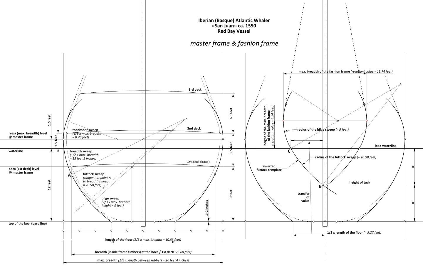
-
Thank you again for your indication. I have already ordered the book . Yet the price of postage even within Europe is equal to or even greater than the price of the book itself, depending on the mode of shipment...
-
Cold War madness
Waldemar replied to Martes's topic in CAD and 3D Modelling/Drafting Plans with Software
Pleasant to look at. In my (albeit rather amateurish in this very field) opinion, these renders are all very appealing, and I find the rendering of the water surface and sky particularly convincing, and at the same time providing atmosphere. As for the ‘technical’ details, this is the first time I have seen a regular cargo truck on the deck of an aircraft carrier. But all in all, this is quite reasonable, given the nature of the activities and the size of these behemoths... -
Iberian (Basque) Atlantic Whaler ca. 1550 — as, dos, tres…
Waldemar replied to Waldemar's topic in Nautical/Naval History
Conceptual frames The longitudinal position of the structural group of pre-assembled frames defined at the same time the position of the three main conceptual frames — master frame, fore quarter frame and aft quarter frame. In this way, that the position of the master frame fell in the middle of this group and both quarter frames at its extremities (see diagram). As a result, the position of the master frame is correspondingly set back from the pre-determined position of the actual middle line of the entire length of the hull. For perfect geometry, the run of the decks must also be adjusted accordingly, bringing it into line with the new position of the ‘middle’ of the hull. In passing, it may also be added that the length of the structural keel (without the vertical scarfs connecting it to the adjacent components of the keel assembly) has already been determined symmetrically to the new position of the ‘middle’ of the hull, i.e. to the position of the conceptual master frame. The structural keel, relative to the design keel, is shorter at its aft end by the length of the heel piece and, in contrast, slightly longer at its fore end, by encompassing the stem post in its design/geometric sense (see diagram).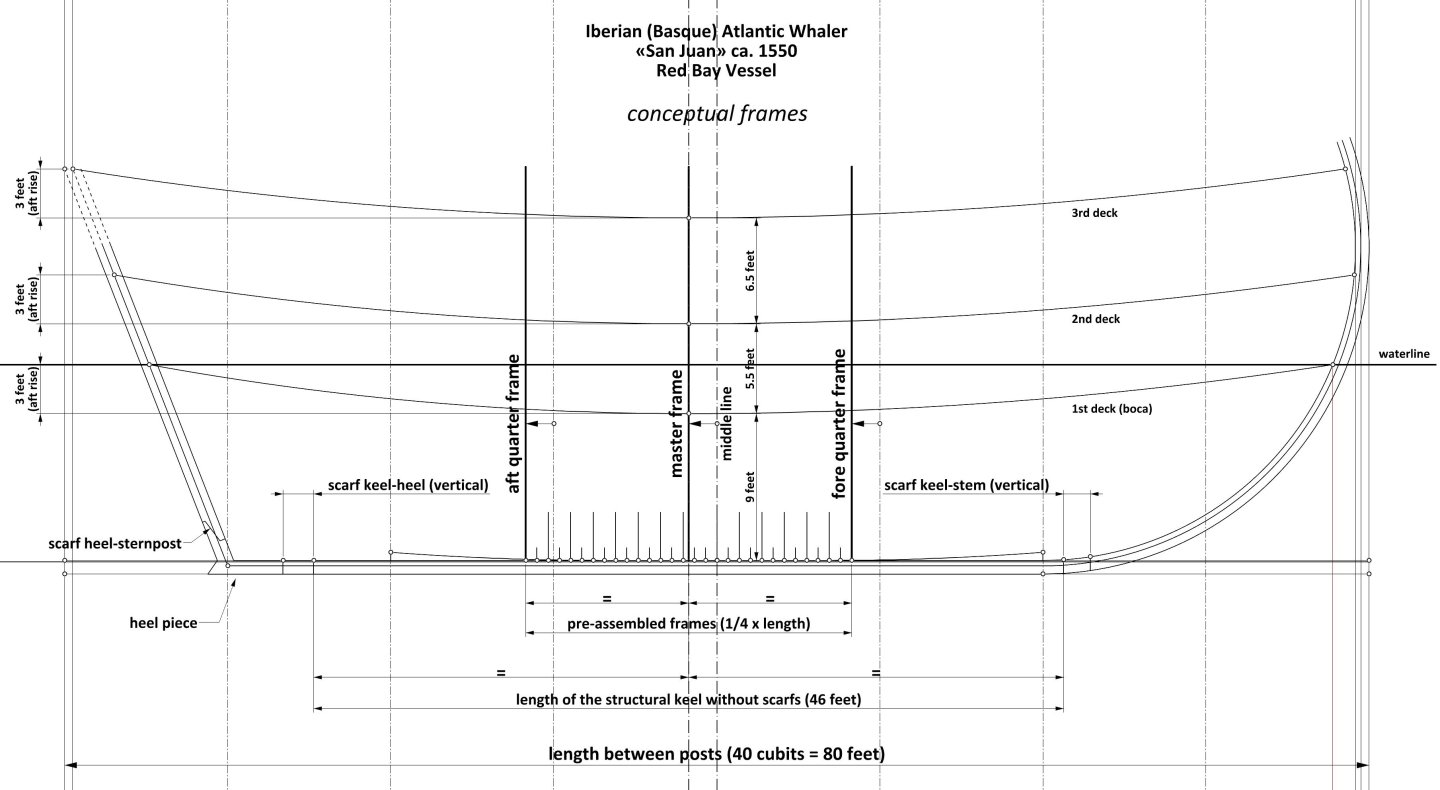
-
Iberian (Basque) Atlantic Whaler ca. 1550 — as, dos, tres…
Waldemar replied to Waldemar's topic in Nautical/Naval History
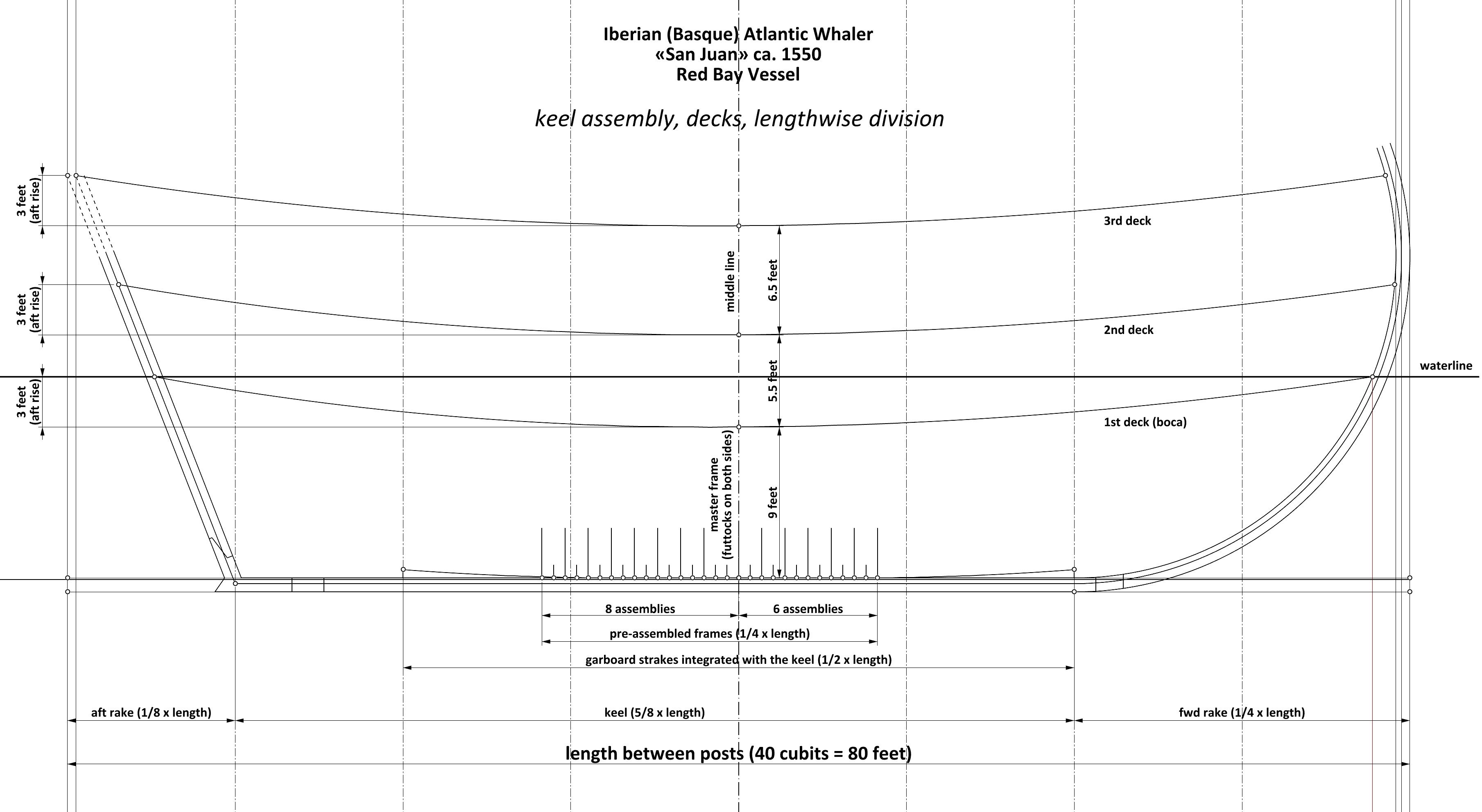
The diagram shown above is almost self explanatory and in principle does not require any extensive comments. It contains the basic design assumptions necessary for the subsequent stages of the ship's hull design. At this first stage, the design sequence for this vessel would look more or less like this: — the length of the hull (between the posts) was set at 40 cubits, or their equivalent of 80 feet, — this length was then divided into eight equal parts of 5 cubits (10 feet) each, — the sum of the two rakes, fore and aft, was set to 3/8 of the length of the hull, in a mutual ratio of 2 : 1, leaving 5/8 of the length of the hull for the keel, — the position of the master frame is half the length of the hull, just behind the middle line (see diagram), — the group of so-called pre-assembled frames includes a total of 14 sub assemblies, for which 1/4 of the length of the hull was provided, asymmetrically in respect to the middle line (see diagram), — the garboard strakes, integrated into the keel, occupy 4/5 of the keel length, starting from the beginning of the keel, — the number, height and rise of the decks, fairly standard for the era, have a direct effect on the height of the two posts, as well as on the angle of the sternpost (the length of the latter will eventually be shortened to allow the tiller to enter the hull below the third deck). -
Iberian (Basque) Atlantic Whaler ca. 1550 — as, dos, tres…
Waldemar replied to Waldemar's topic in Nautical/Naval History

-
Paviljoensjacht 1733 | Blender
Waldemar replied to Robska's topic in CAD and 3D Modelling/Drafting Plans with Software
Admittedly, I'm not quite sure what the term ‘on top of the current hull form’ means , however, the issue of applying the hull planking thickness is so trivial that it doesn't even need an explanatory diagram. Simply increase the thickness of the existing surface (now zero thickness) to one and a half inches, towards the outside of the hull. This will result in two surfaces parallel to each other, one and a half inches apart, enclosing the volume of the planking. Notwithstanding, it may still be worth showing the suggested run of planking at the bow. In fact, due to its rather peculiar shape, it would not have been possible (or extremely hard) to plank this yacht in any particularly different fashion anyway. Or, at the least, in the shown manner of planking the hull surface, edge bending of the planking boards (in the real, full size construction) would be reduced to a minimum. Oh, and also perhaps that the transom flat (at the stern) is on the outside of the planking, opposite to the rest.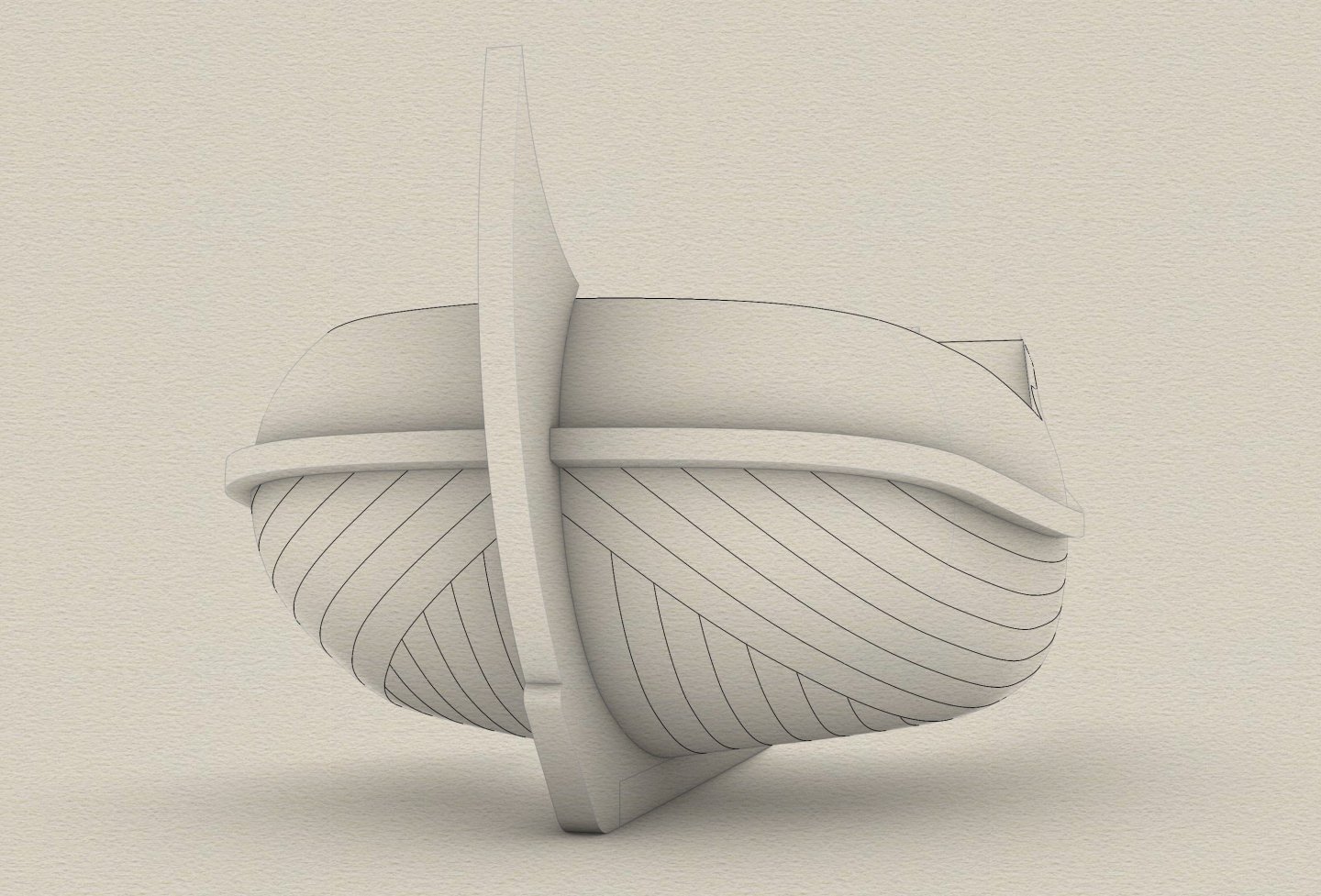
-
Paviljoensjacht 1733 | Blender
Waldemar replied to Robska's topic in CAD and 3D Modelling/Drafting Plans with Software
That's fine. It gives me some relief, particularly in view of future such conversions, that the matter has been cleared up. Then there is the issue that I did not write about in the private message. I have defined the hull surface inside planking, and for your convenience the width of the keel assembly follows the inner rabbet lines, which effectively have always a diminishing width, especially towards the stern end. In this way, in the provided 3D model, the keel and hull surface edges coincide. This is quite a suitable configuration for a variant where you will not be adding thickness of the planking — you can simply leave it as it is now, and you have ready-made 3D models of both elements. However, if you decide to add thickness of the planking, remember that you should then make a new keel assembly. I have contrived it in the way to make the job as easy as possible for you — it is enough to make new, replacement keel assembly of uniform width over its entire length. This width should be the same as the greatest width of the current keel. For the thickness of the planking, I have provided one and a half inches. The uncertainty of your decision in this matter is also the reason why I wrote that you will have to optionally redefine some extra elements in the 3D model provided. Good luck! -
Iberian (Basque) Atlantic Whaler ca. 1550 — as, dos, tres…
Waldemar replied to Waldemar's topic in Nautical/Naval History
Indeed, the difficulty in understanding is not helpful probably in any venture. And it's nice that you also seek some help here . -
Iberian (Basque) Atlantic Whaler ca. 1550 — as, dos, tres…
Waldemar replied to Waldemar's topic in Nautical/Naval History
Am I misunderstanding something? As, dos, tres doesn't sound like a long ship to me. -
Paviljoensjacht 1733 | Blender
Waldemar replied to Robska's topic in CAD and 3D Modelling/Drafting Plans with Software
I was a little concerned about your comment regarding possible typological errors in the 3D model mesh I provided to you, which was obtained by preceding automatic conversion from NURBS-type geometry. Therefore, in order to avoid possible faults of this kind in the future, I asked an expert in mesh geometry modelling to find and point out to me any errors in this mesh. Here is his assessment: It definitely is an automatically generated mesh, but it appears as perfect as such mesh can be, I see nothing wrong with this model, nor any trace of manual corrections. -
Iberian (Basque) Atlantic Whaler ca. 1550 — as, dos, tres…
Waldemar replied to Waldemar's topic in Nautical/Naval History
Thank you, @Doreltomin. Interesting and erudite posts are always welcome . -
Iberian (Basque) Atlantic Whaler ca. 1550 — as, dos, tres…
Waldemar replied to Waldemar's topic in Nautical/Naval History
The general proportions (as, dos, tres) do indeed correspond to what is usually referred to as nao or carrack, but already the way the hull shapes are formed is more universal and was employed for a variety of vessel types of a very different proportions. In fact, it is most suitable for long galley-type vessels. As a curiosity I will also say that the length-to-width ratio of this ship at the height of the waterline is only about 2.8 : 1, and apparently these vessels were able to cross the ocean successfully and in both directions . Thanks precisely to these quite pointed hull lines. However, at the expense of payload capacity... -
Paviljoensjacht 1733 | Blender
Waldemar replied to Robska's topic in CAD and 3D Modelling/Drafting Plans with Software
The transom timbers at the stern and the wales at the side are essentially pieces of wood independent of each other, but are usually put at the same height so that they can be firmly connected to each other using a knees inside the hull. This is quite important for the structural integrity of the whole vessel. Later it occurred to me that maybe others might also want to play with this 3D model of the yacht in some way. Without any restrictions. The model is in the form of a mesh and is saved in OBJ format, so that it can be imported into 3D programs that support just meshes (as opposed to NURBS type elements). Paviljoensjacht 1733.obj -
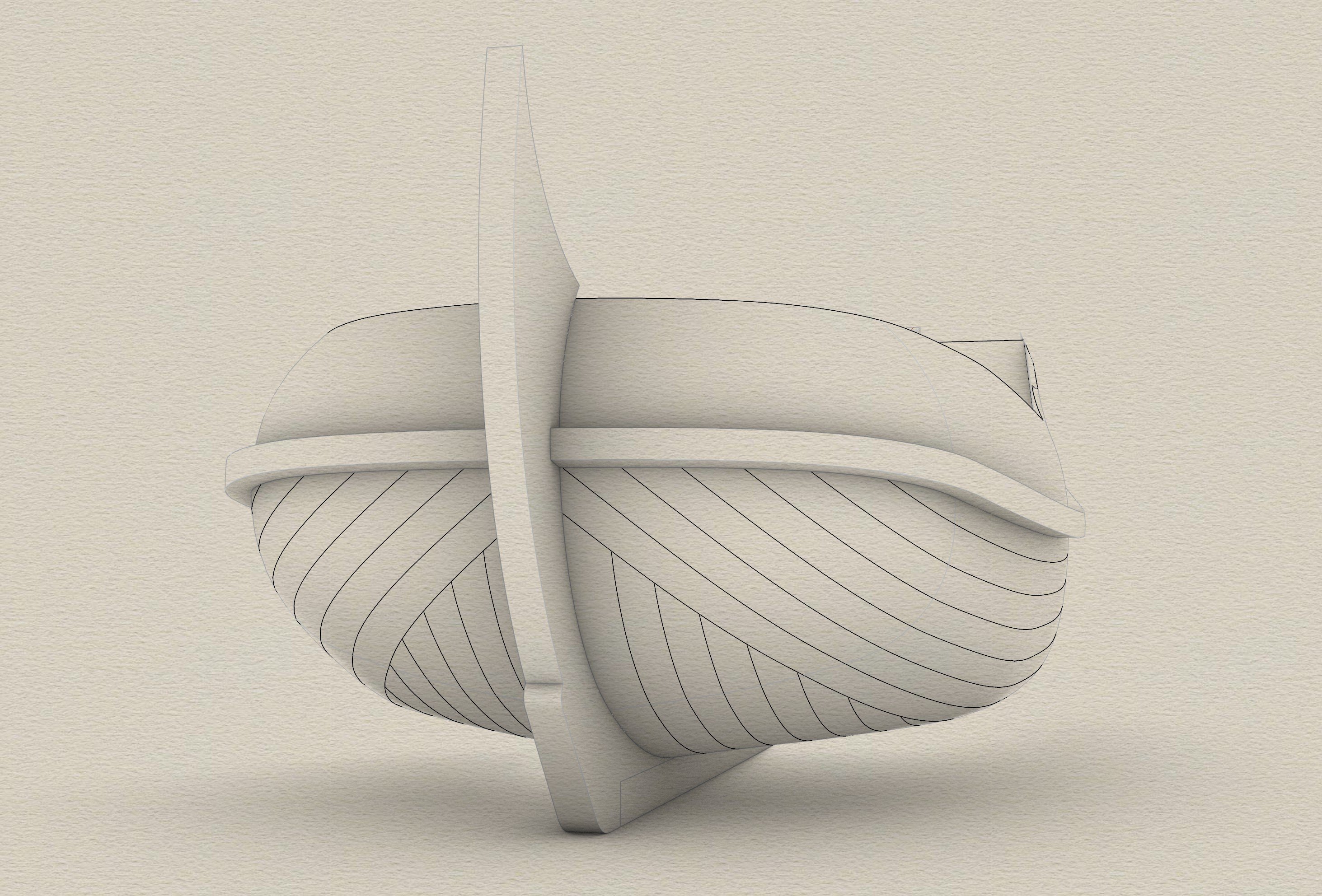
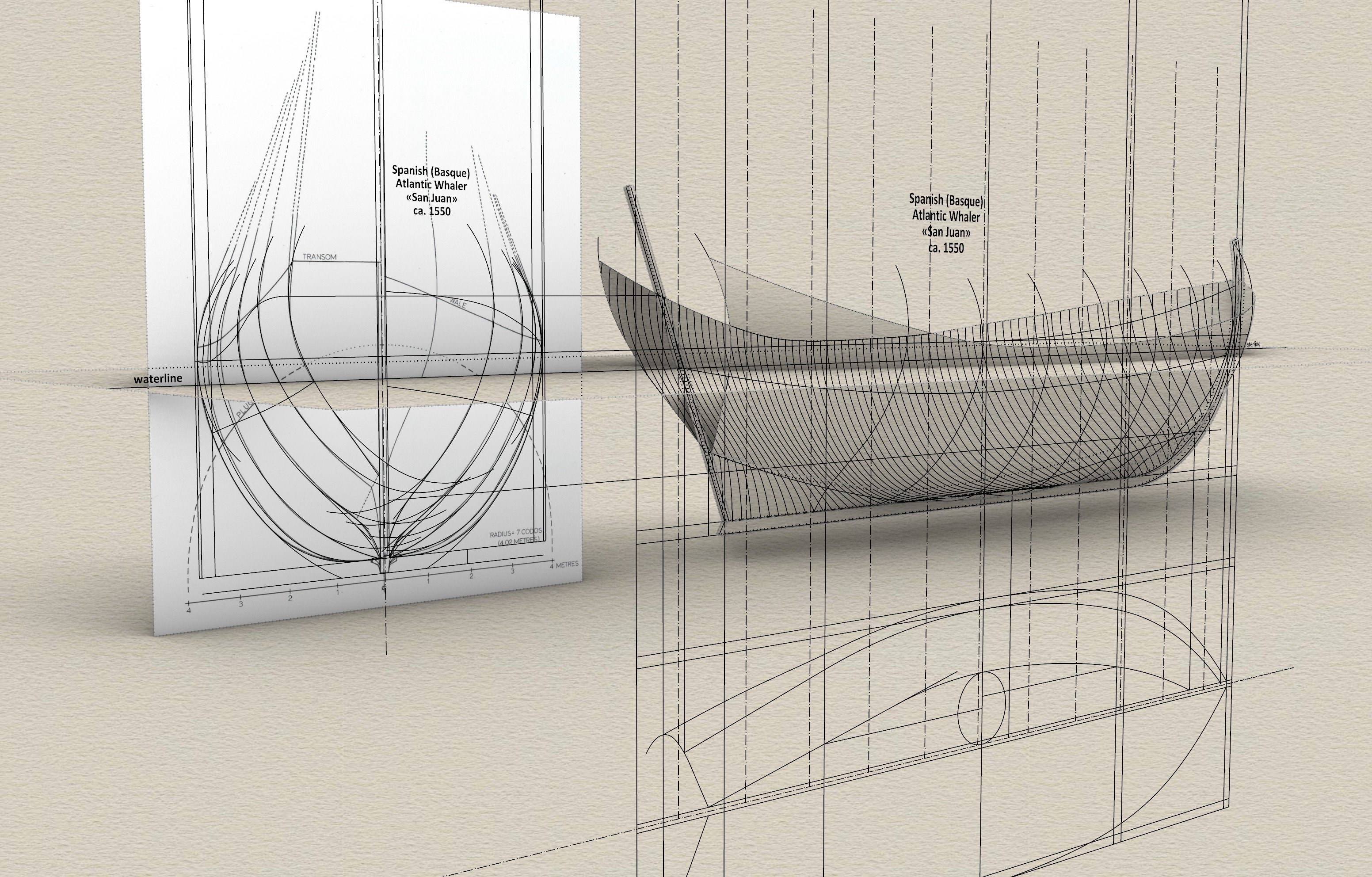
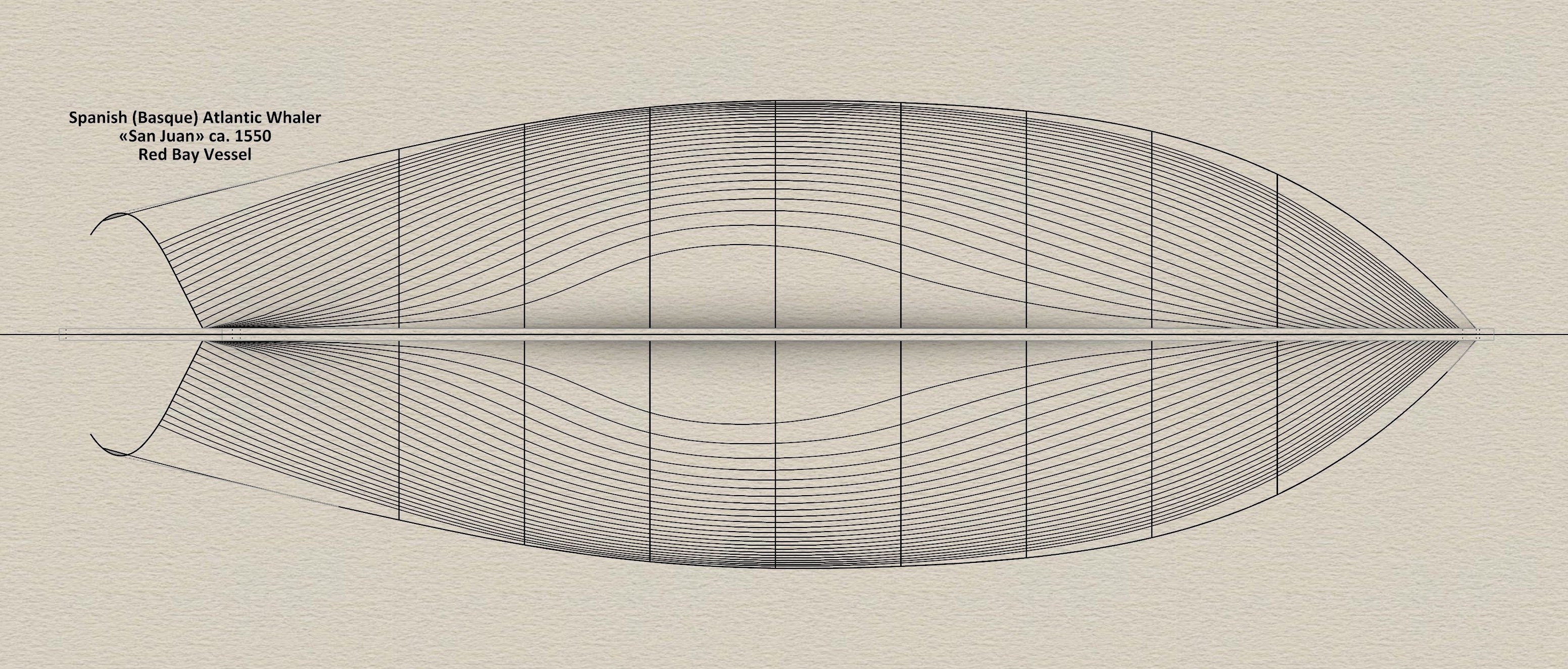
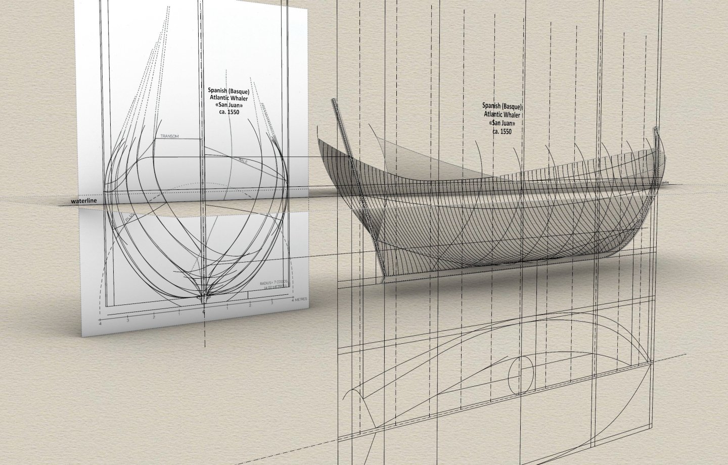
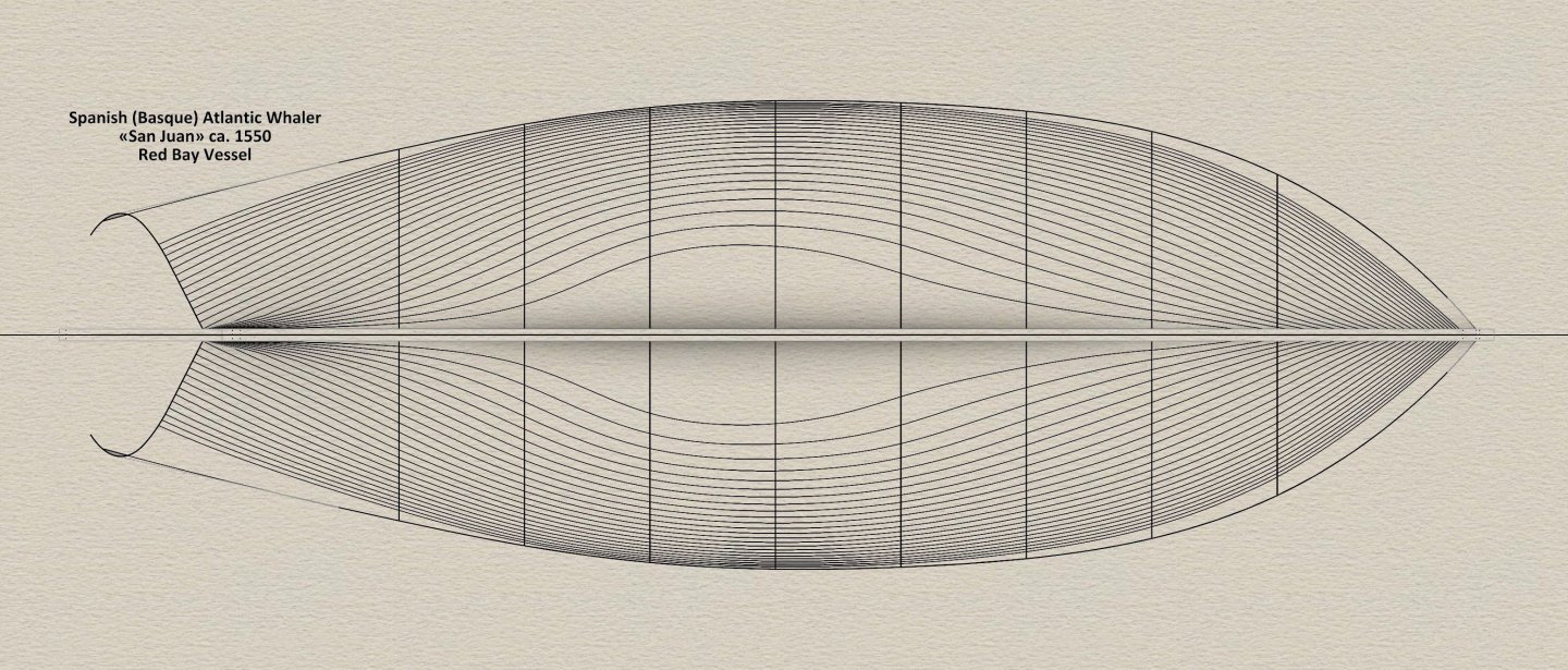
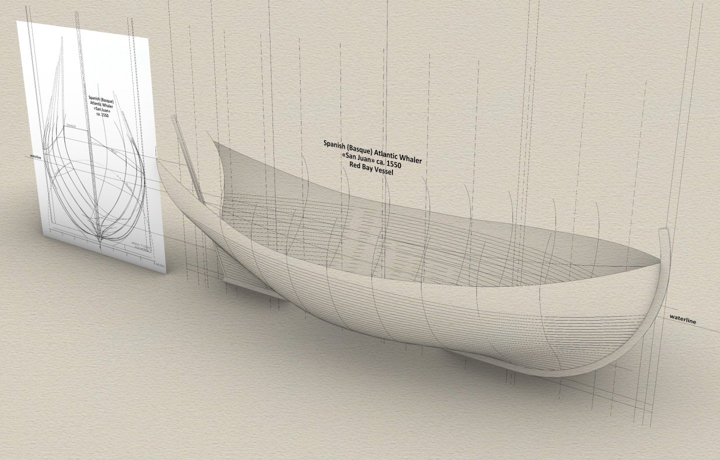
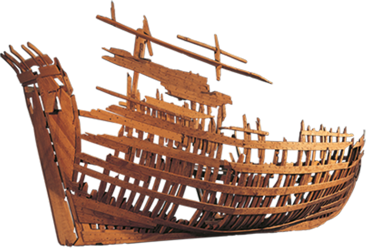
Although the extremely important wreck of a mid-16th century seagoing ship built in the Basque region of Spain has already been studied in great detail and presented to the public in the comprehensive, multi-volume monograph The Underwater Archaeology Red Bay. Basque Shipbuilding and Whaling in the 16th Century, published by Parcs Canada in 2007, nevertheless, the following presentation will not be a repetition of the material contained therein, but rather to complement certain omissions or even a different interpretation of this archaeological find. In a nutshell, the aim of this exercise is to recreate and present the method of designing a ship in terms of its geometrical conception, an issue that is fundamental to naval architecture and yet so little understood today for the early modern period. Somewhat retrospectively, it can already be said that the Red Bay Vessel is an example of the then classic proportion as, dos, tres (breadth : keel length : total length = 1 : 2 : 3), recommended by authors of numerous works of the period, and applied in this particular case in a very literal, astonishingly precise manner. Apart from the main proportions of the ship, no less important from the point of view of the history of naval architecture is the method used to form the shape of the hull, and taking into account its specific details. In this ship, one of the widespread Mediterranean methods of hull forming was used, which, nota bene, was also adopted at about this time in England, and was still used there in its generic form in the first decades of the 17th century, before being creatively developed into the more sophisticated ways generally referred to today as English moulding. Archaeological model of the wreck of San Juan, the Basque whaling ship, scale 1:10 (Parcs Canada) Shapes of the ship's hull reproduced by applying the found method of designing the vessel: In addition to the monograph of the wreck itself, which may be not available to everyone, much interesting material regarding the hull structure of the shipwreck can also be found in the provided below publication by Robert Grenier, The Basque whaling ship from Red Bay, 2001 (public domain). Grenier Robert - The basque whaling ship from Red Bay - 2001.pdf
- 17 replies
-
- 14
-

-
Eventually, out of curiosity, I had a look at the archaeological report myself. It turns out, quite logically, that the ordinary planking boards were of pine, while those of structural importance, where the individual timbers overlap (i.e. floor, bilge, futtock timbers) were of the more robust oak. The latter were also thicker than regular planking, in effect making them a sort of underwater wales. The report also points out that the use of coniferous wood in the Mediterranean for the planking of ship hulls was quite standard practice at the time.
-
Is there any regularity of application in this mix of two wood species or does it look more random? What is in the report about this? Because if it's a bit of a haphazard-looking mix, then repairs, necessarily done quite routinely and arguably at varying levels of cost and resulting quality, can probably also be added to these possibilities.
-
It depends on where the pine (coniferous wood) is used. If for the lower parts of the hull planking, then yes, it could have been a cheat. However, if for the upper parts of the hull (especially the planking of the upper decks, even the planking of the upper sides, or for the inner bulkheads, regardless of their location), then it is already a most correct and desirable practice, advised and described in the ship's handbooks of the period. It is particularly about the difference in weight of oak (or other heavy woods) from coniferous species. As a curiosity — at that time or so, in the north of the continent, there were in fact quite a few ships built entirely of coniferous wood. They were called fyrblasses (in Germanic languages fyr or similar, meaning precisely pine wood).
-
Paviljoensjacht 1733 | Blender
Waldemar replied to Robska's topic in CAD and 3D Modelling/Drafting Plans with Software
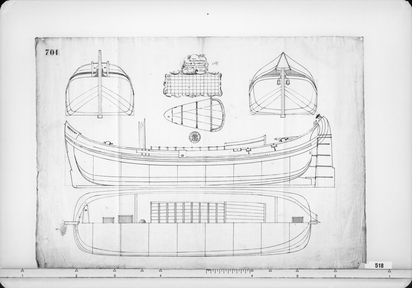
Correct — Veltman, not Veltmand. The alleged letter ‘d’ is just a fragment of a leaf. But it's best to see it for yourself. link: | Nationaal Archief ... and in its entirety: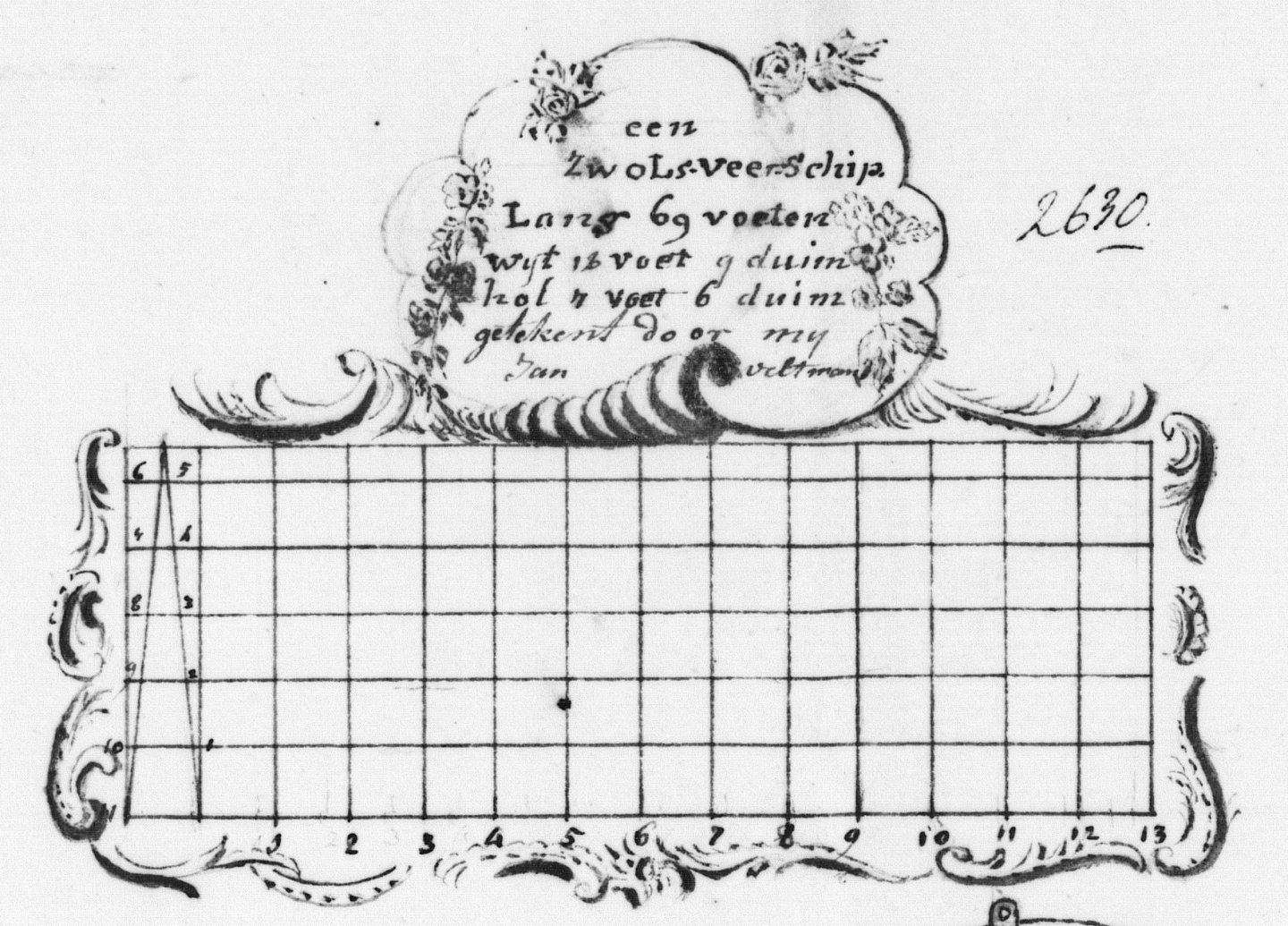
-
Paviljoensjacht 1733 | Blender
Waldemar replied to Robska's topic in CAD and 3D Modelling/Drafting Plans with Software
To be honest, I hadn't really paid attention to this very detail. Congratulations on your perceptiveness! The designs of this Jan Veltmand are very recognisable from others, and cover a whole range of different vessels. Yet, his full name is found on only one of his draughts. And here, his initials, nice...