HOLIDAY DONATION DRIVE - SUPPORT MSW - DO YOUR PART TO KEEP THIS GREAT FORUM GOING! (Only 24 donations so far out of 49,000 members - C'mon guys!)
×
Richard Dunn
-
Posts
529 -
Joined
-
Last visited
Content Type
Profiles
Forums
Gallery
Events
Everything posted by Richard Dunn
-
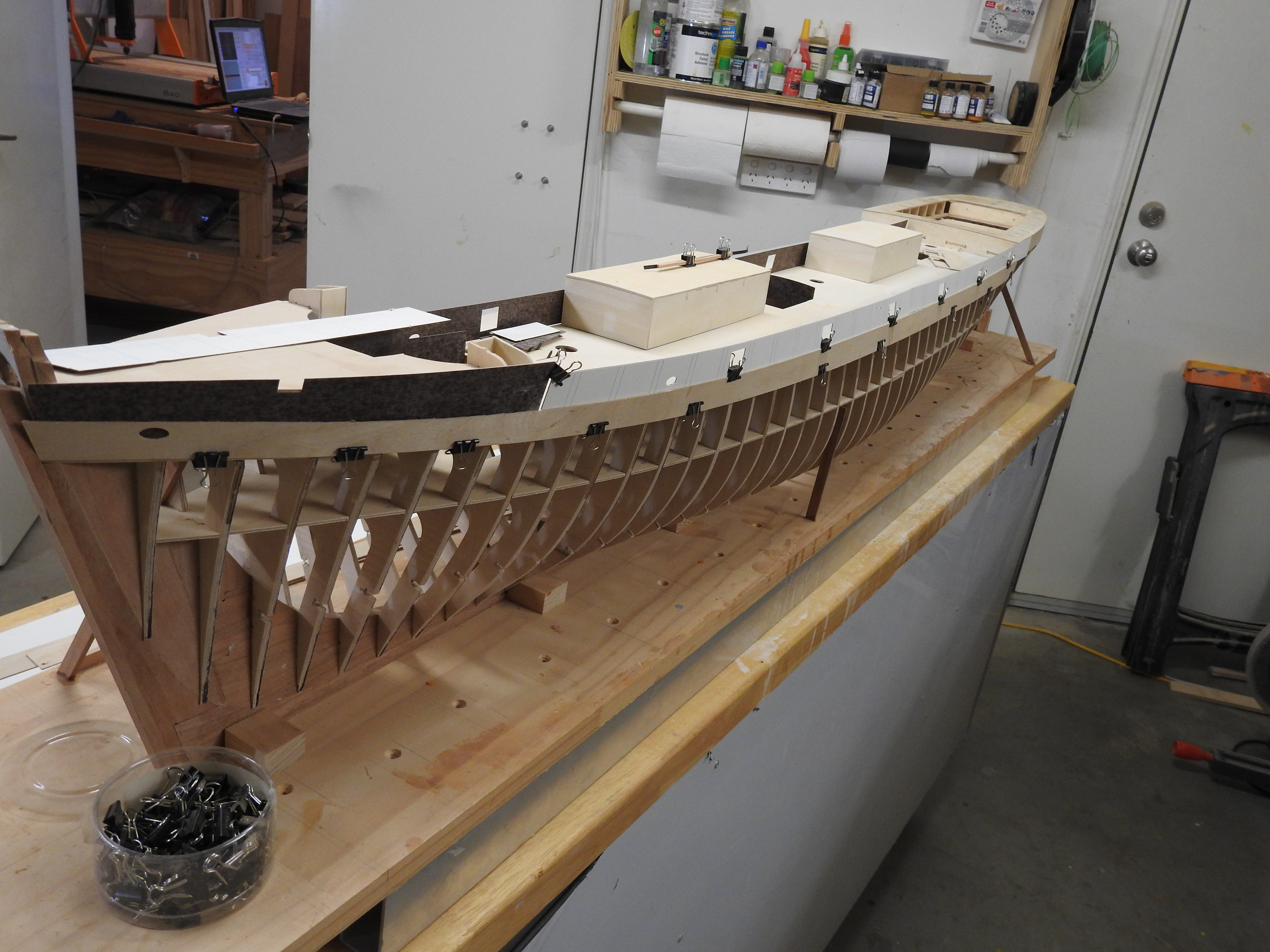
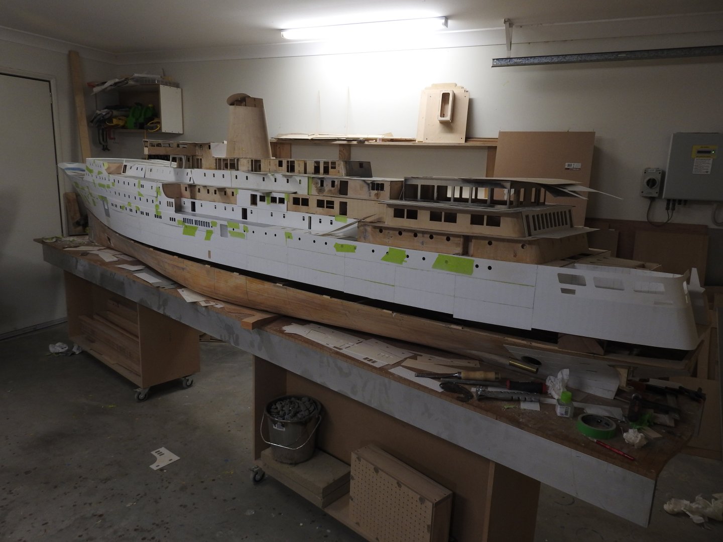
 A slight delay in progress again, I have been asked to build another shell of this ship at same scale in a much simpler way so currenty framing that up while mine sits in our hallway in the house. Thank gawd for wide hallways....
- 454 replies
-
- 2
-

-
- Union Steamship Company
- Stepcraft 840
- (and 3 more)
-
I had never thought of it like that, I guess in a way it is the same thing
-
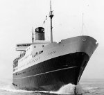
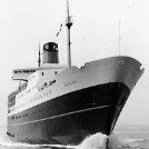
I stand corrected, wow, not the most elegant things. I forget she is a rebuild I was meaning the original boat in the B/W images.
-
I am a stickler for accuracy, but even I would be putting in conventional Goosenecks or leaving them off I think.,I think you can guarantee it would not have been built with those...... Are there any old photos that could show what was there?
-
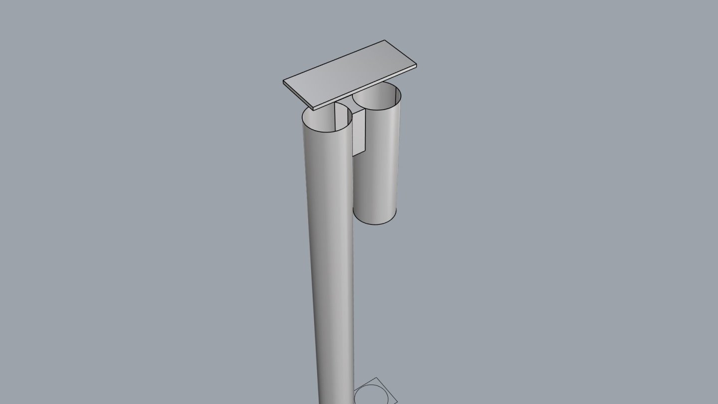
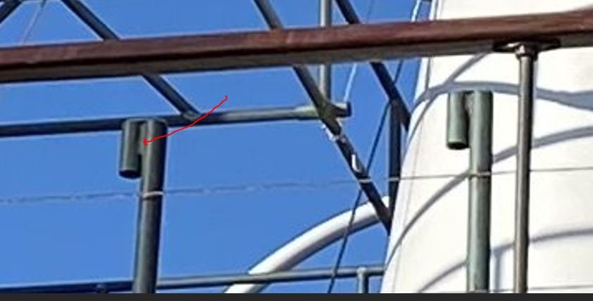
I had a close look and I think they are custom made gooseneck vents as John said, made by someone who was unable to bend the pipe in the usual way, if you look at the close up you can see a connecting part. I blocked it out in 3d to illustrate the possible arrangment. The placement would also suggest this, but if you have a plan showing hull voids/tanks it would confirm it.
-
Haha.. well this model is built from 480 of those. that is one of the more complex ones I admit
-
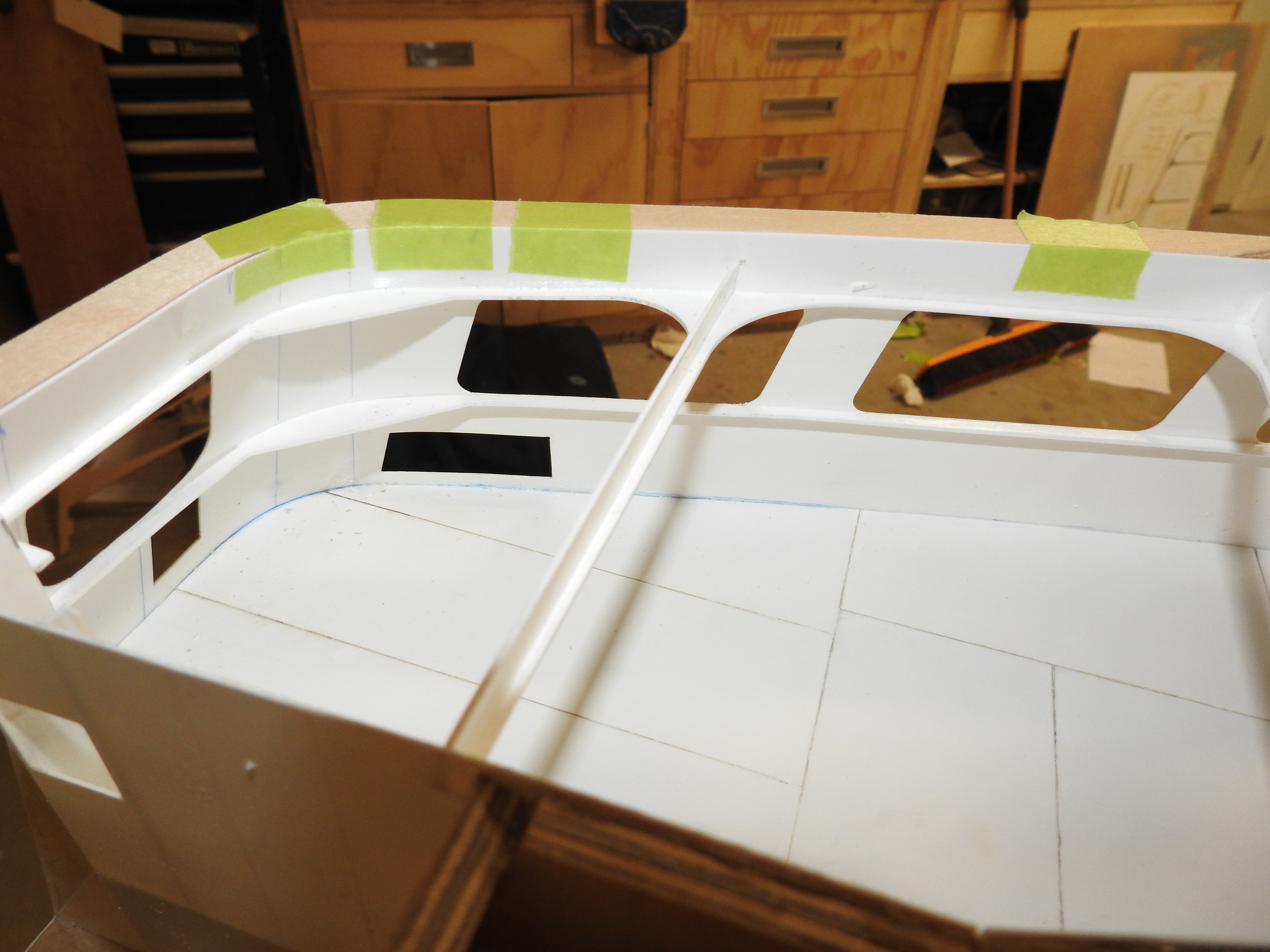
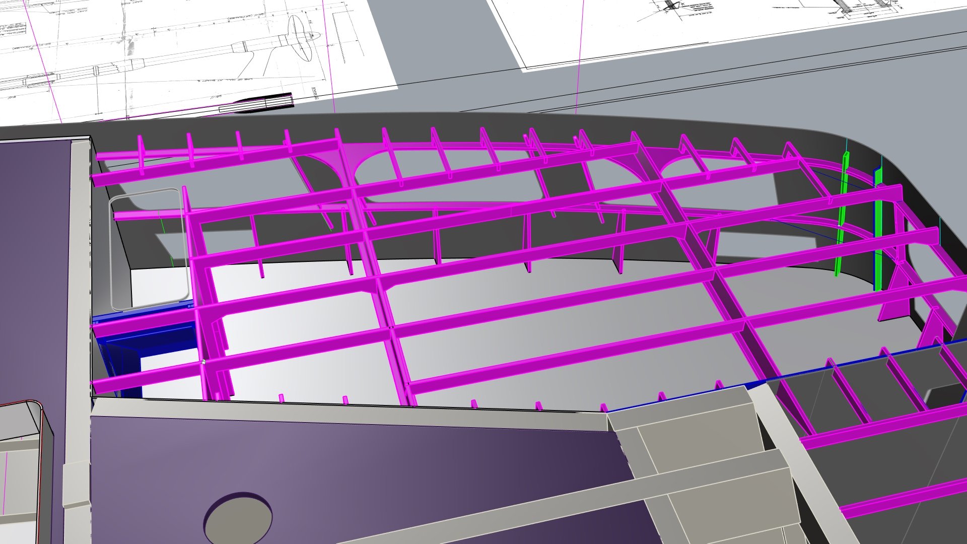
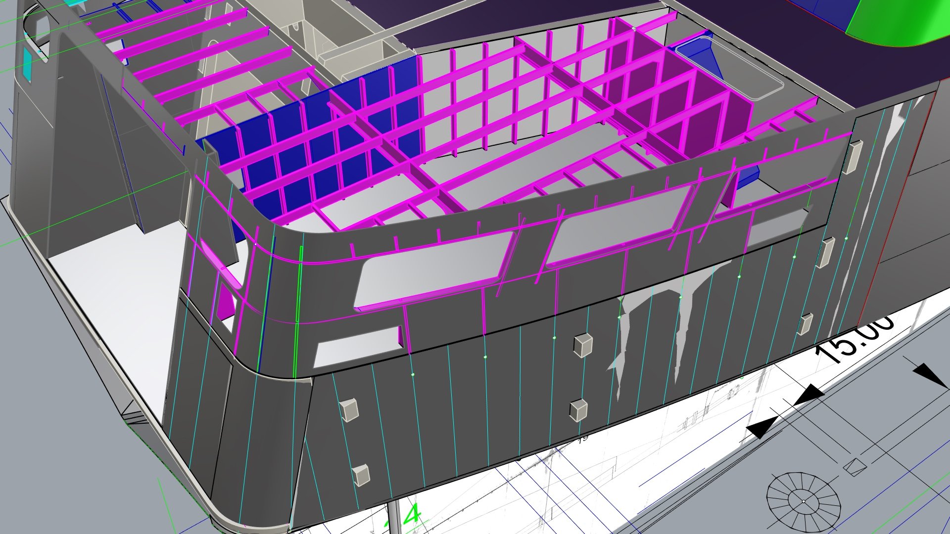
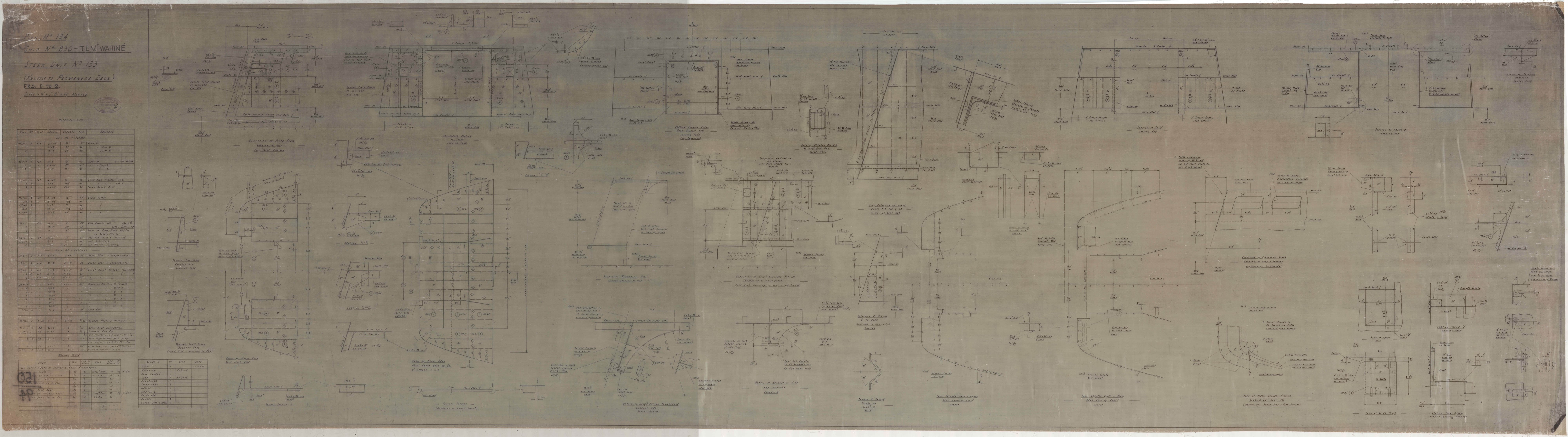
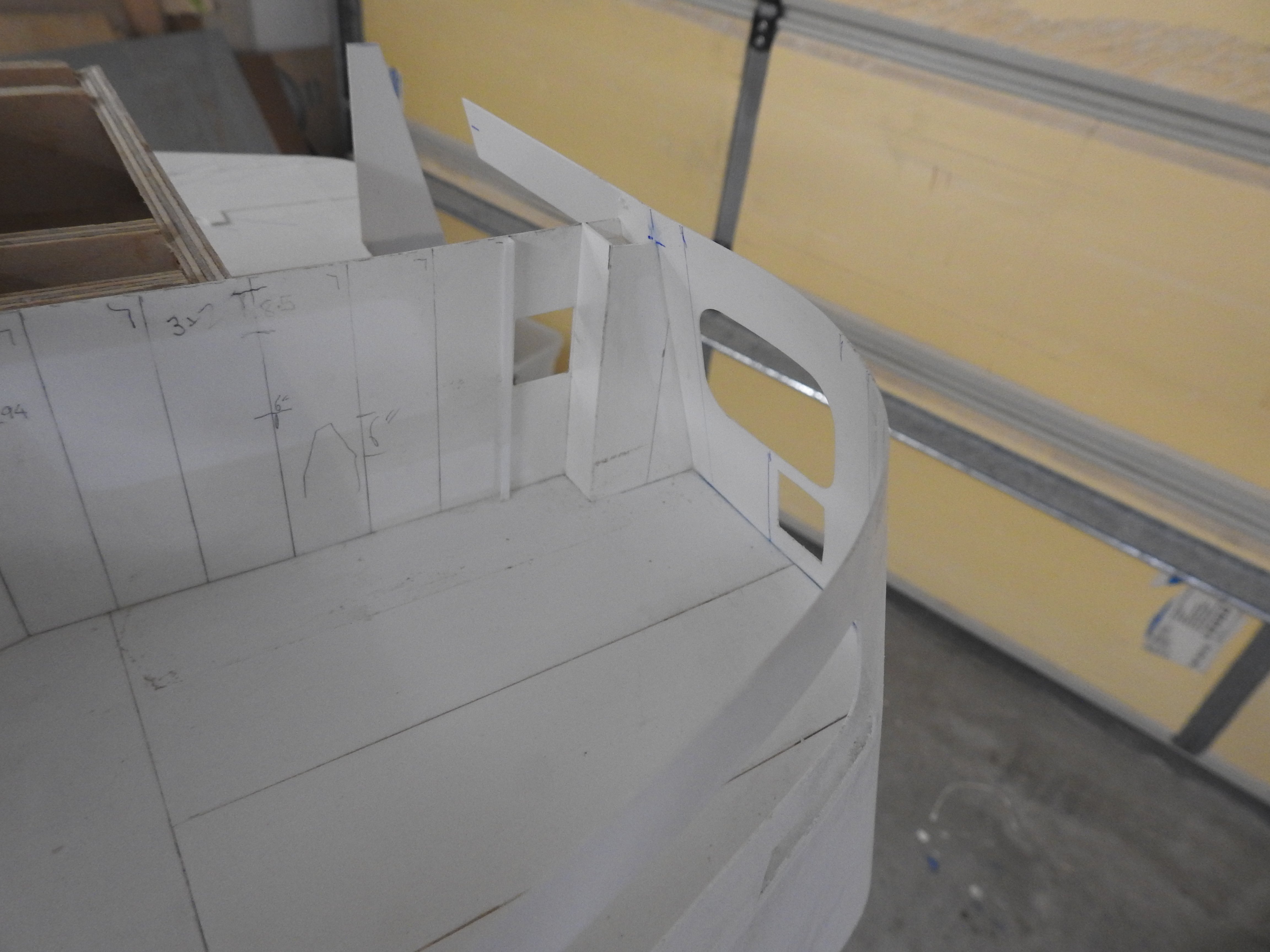
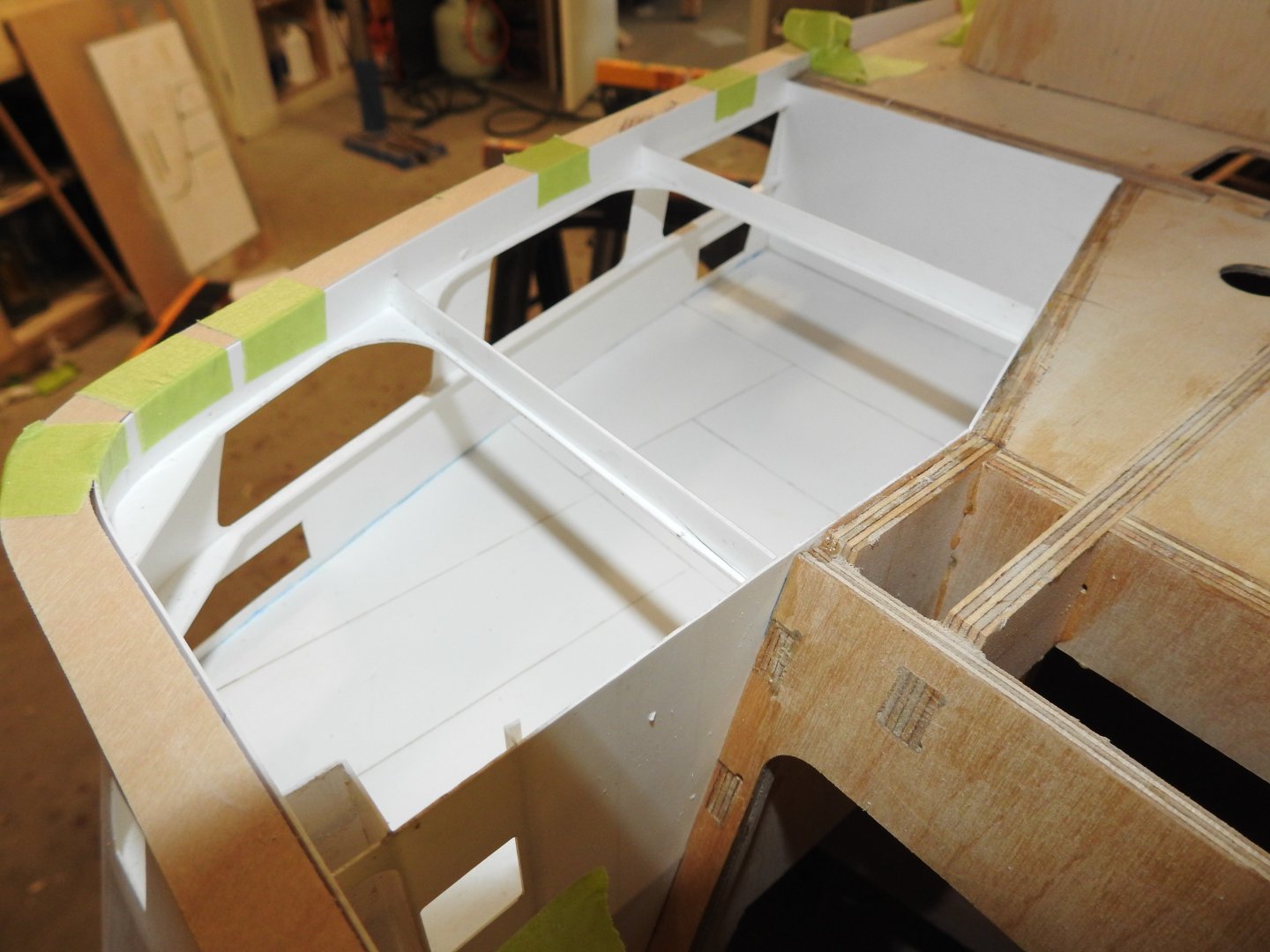
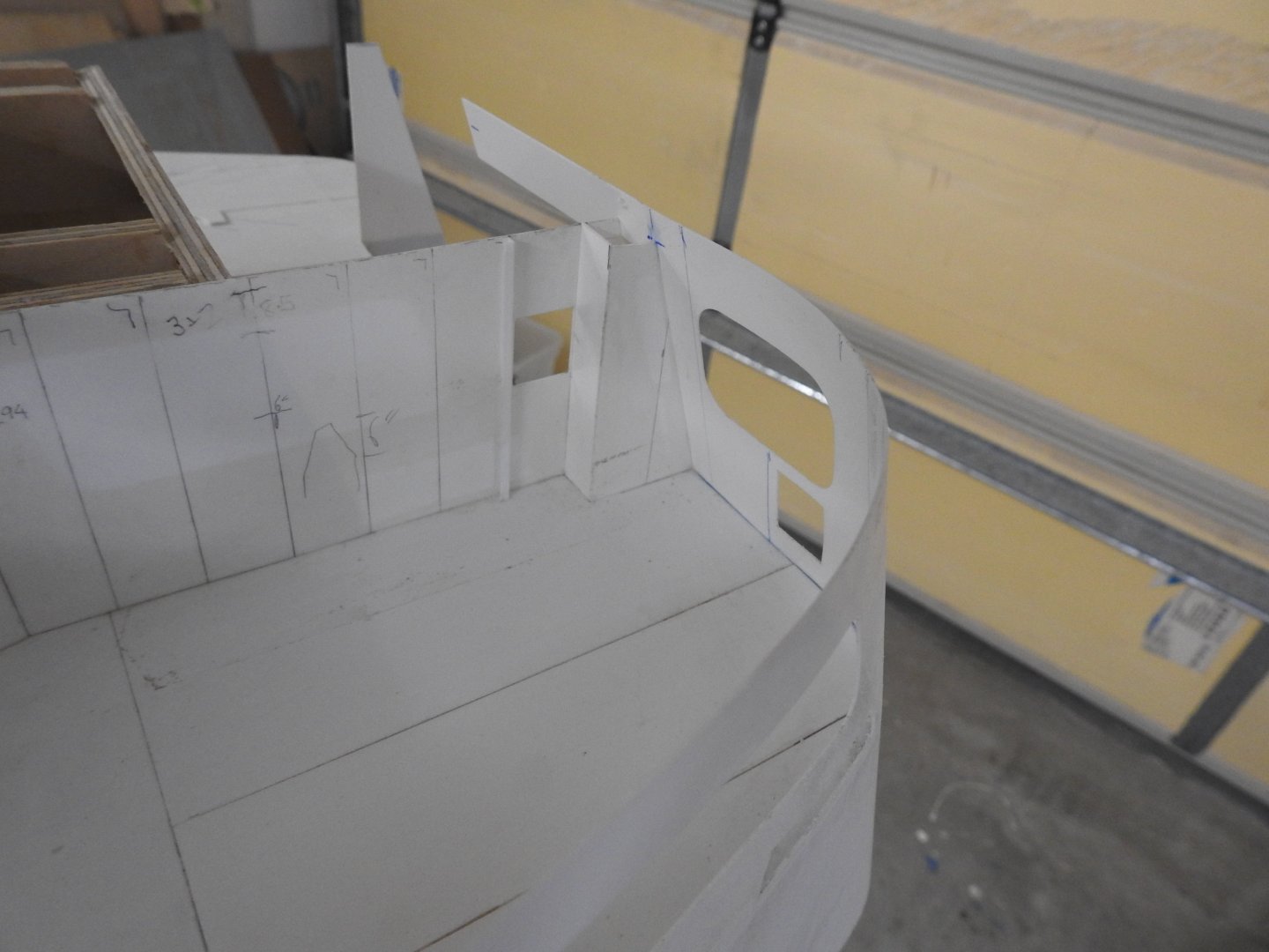
Has anyone used PVA as a glazing mask? on acrylic Some framing started on Port aft mooring deck, these stringers above and below the openings were VERY hard to fit into place and keep flush with holes, I think I invented some new words during this. Once the Bulwark stays go in this should be quite stiff. A couple of renders of the framing in here as a whole. And just for the few hard core people actually reading this. here is the actual plan to compare to of the aft part of this, the forward part with stair well does not exist. knock yourself out. I know a lot of people are probably say " why are you going to all the trouble of framing all this up", well Its always been one of my life goals to have this on my model, it's very important to me, at at this scale I feel it's a given.


- 454 replies
-
- 6
-

-
-
- Union Steamship Company
- Stepcraft 840
- (and 3 more)
-
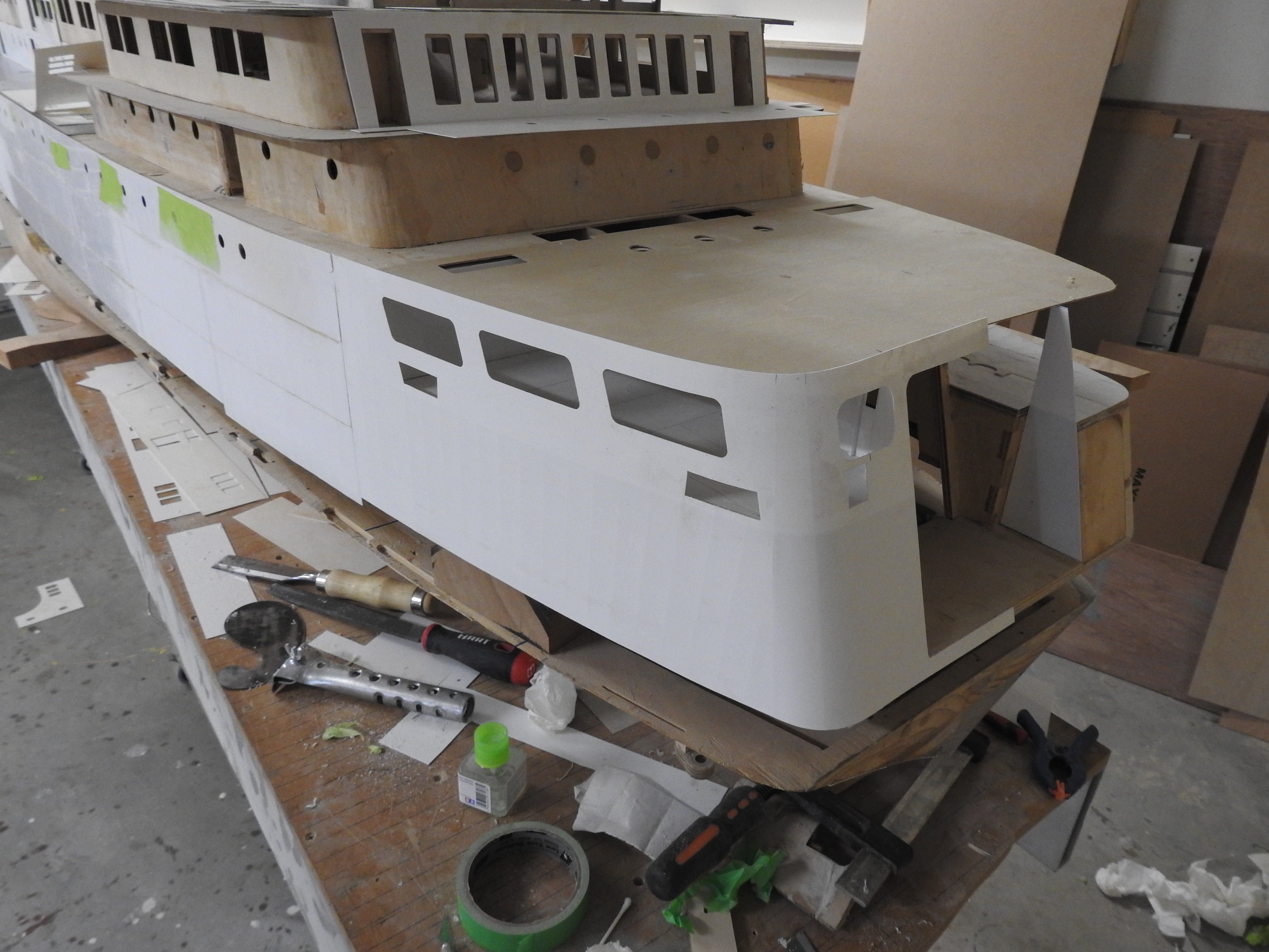
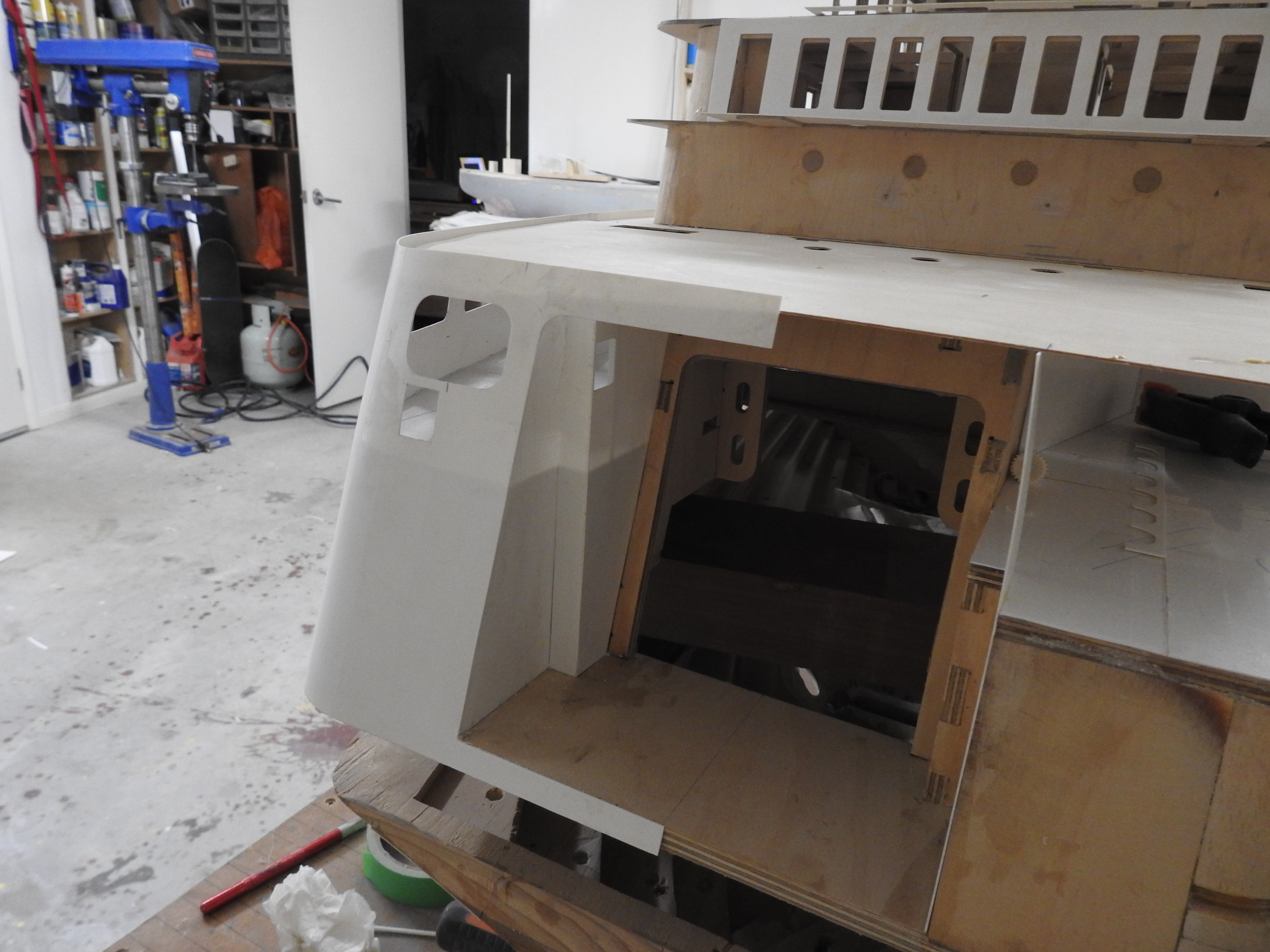
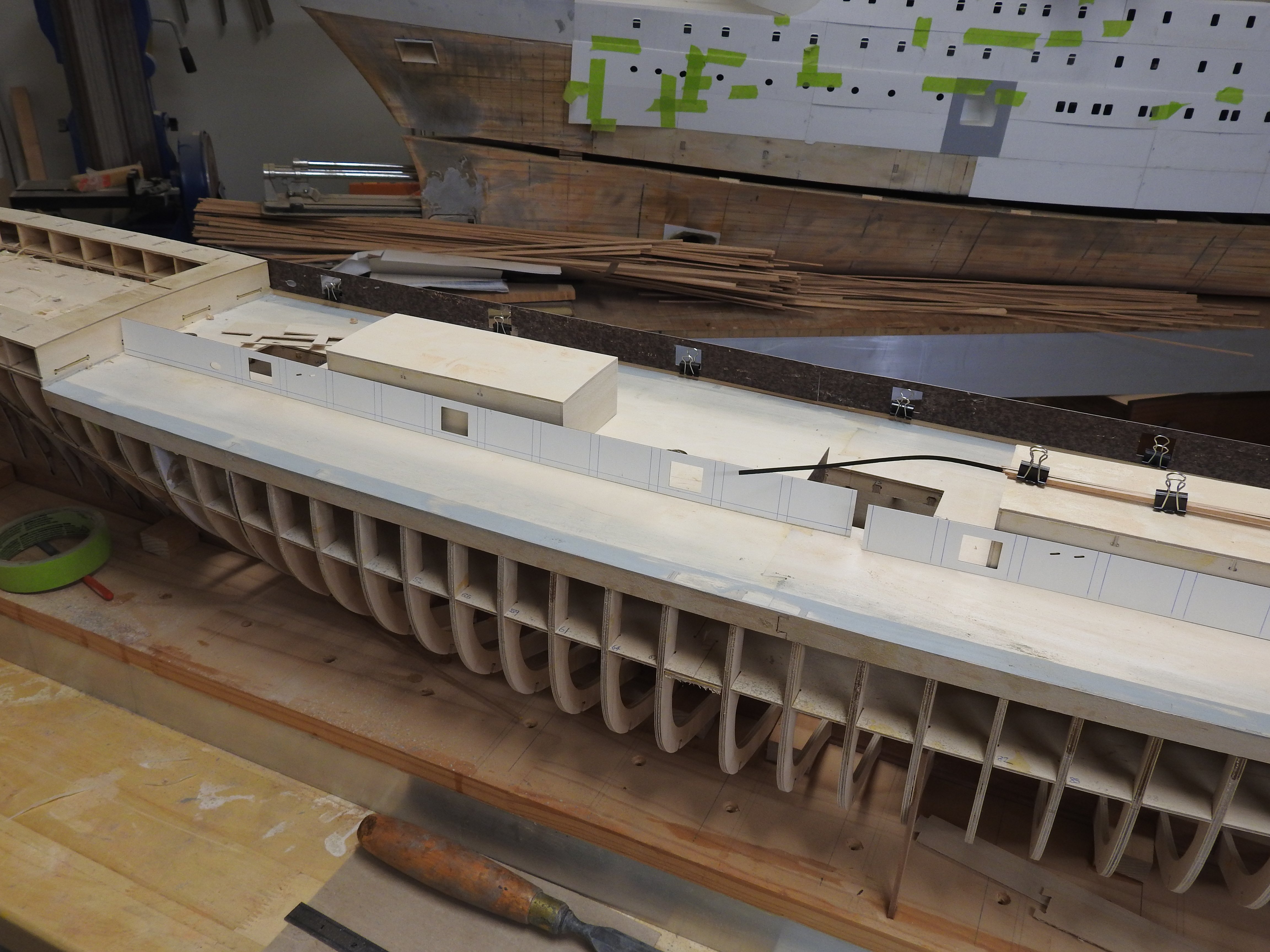
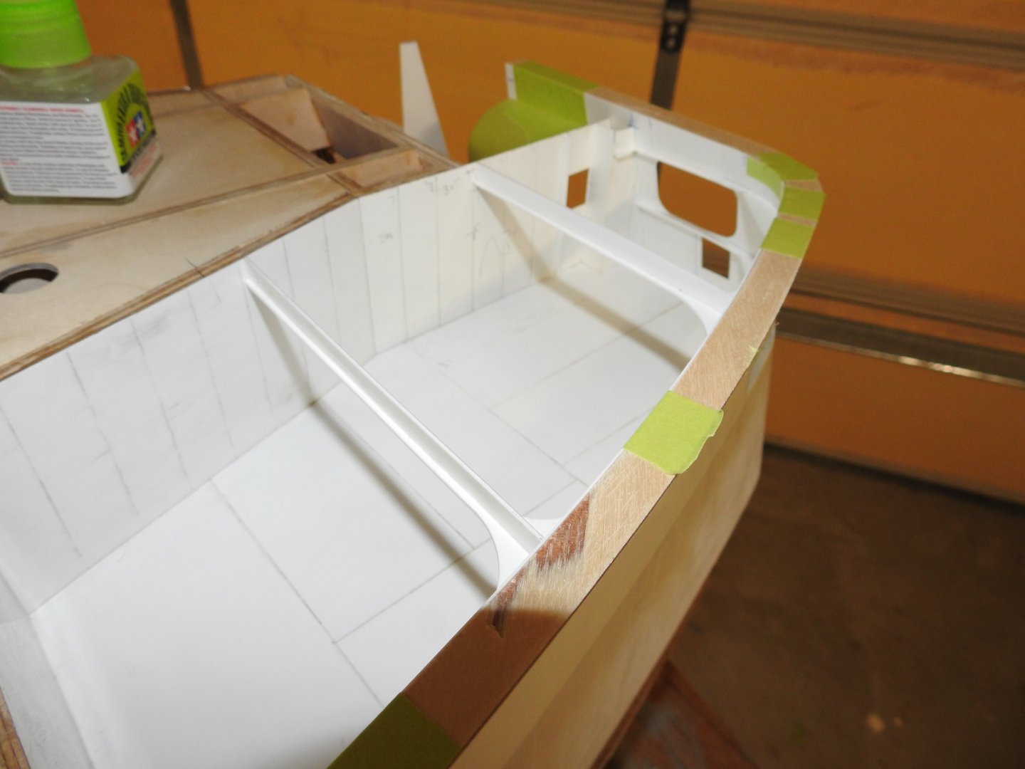
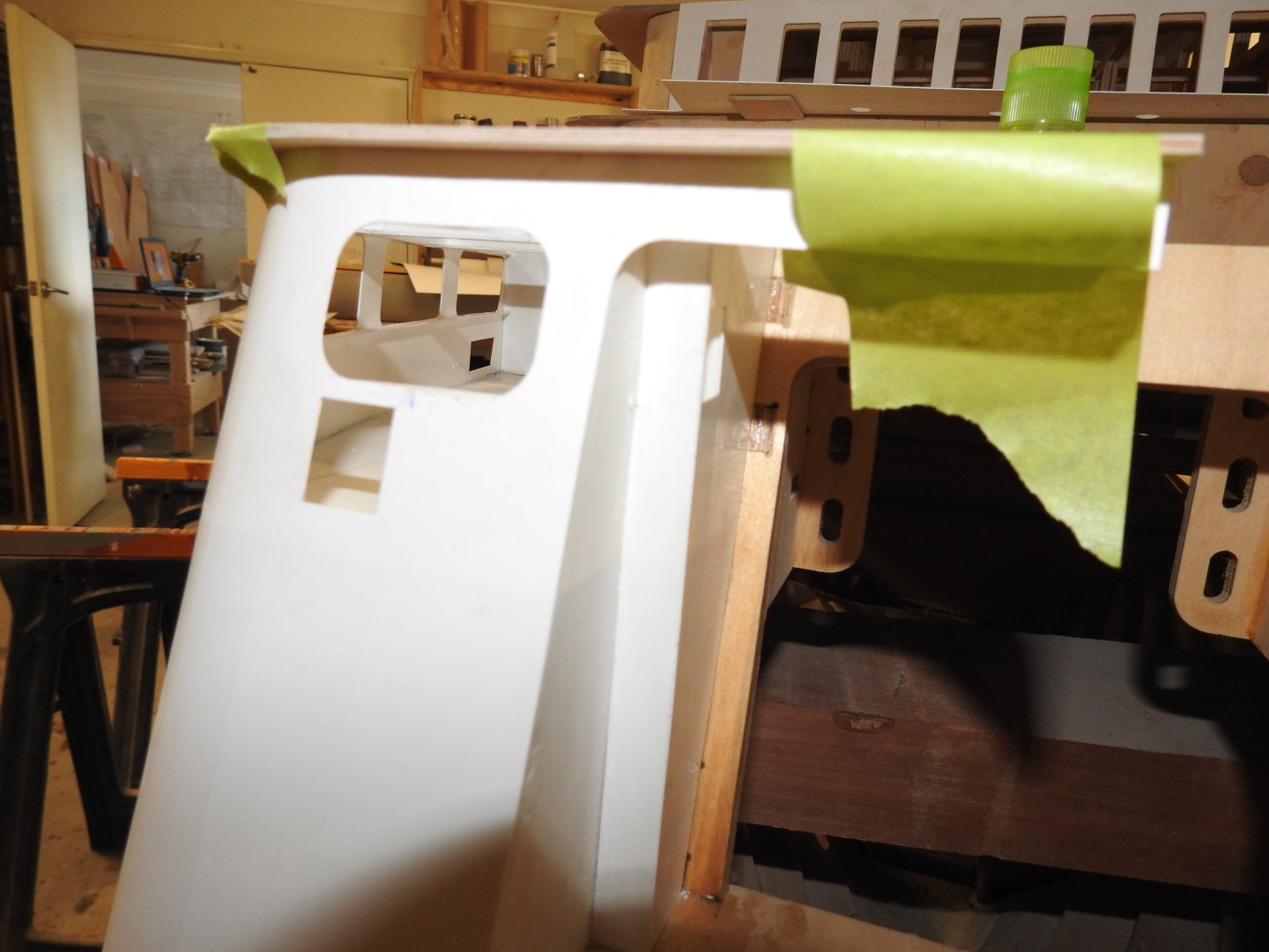
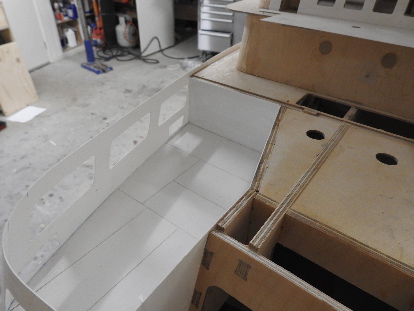
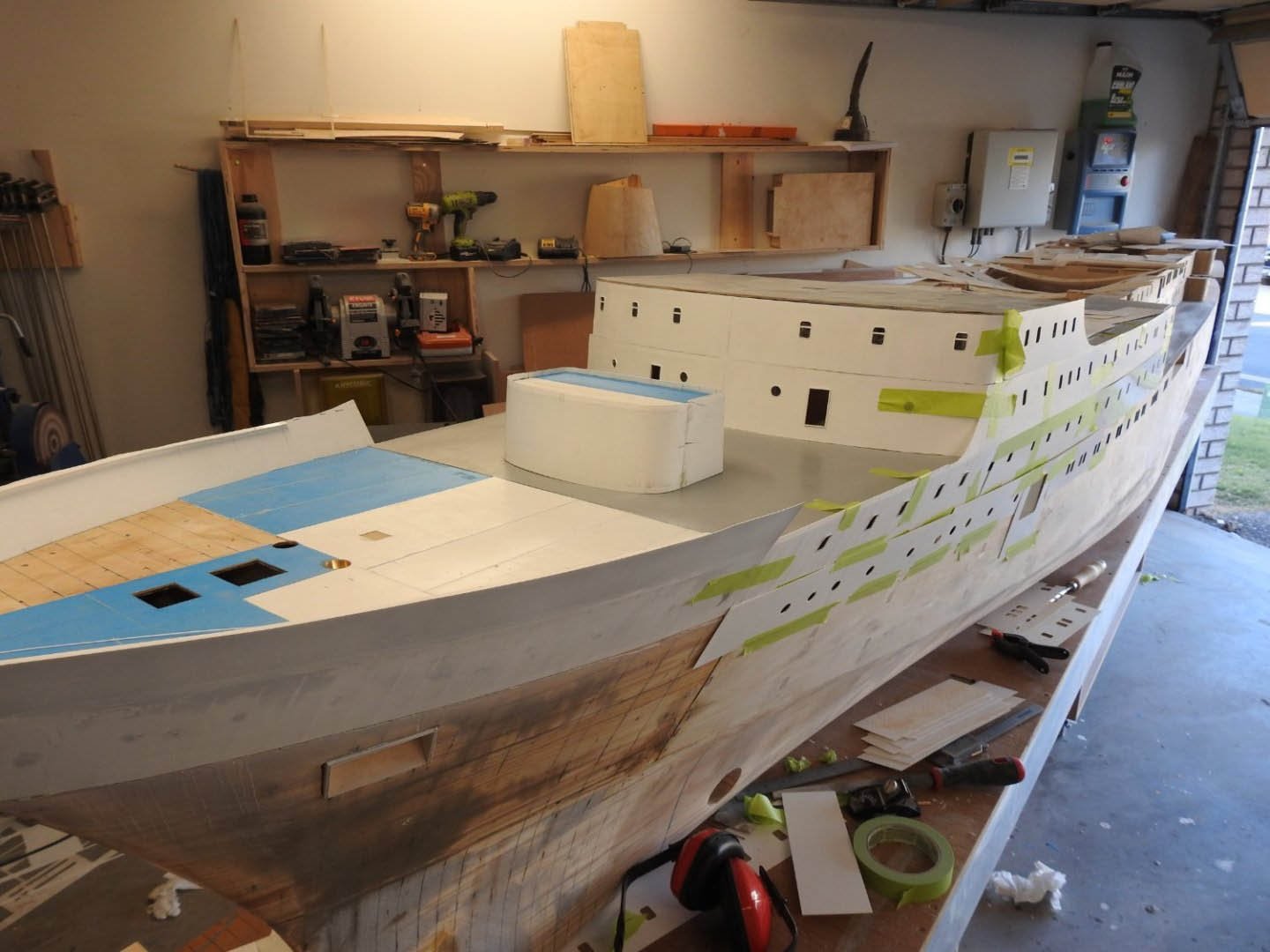
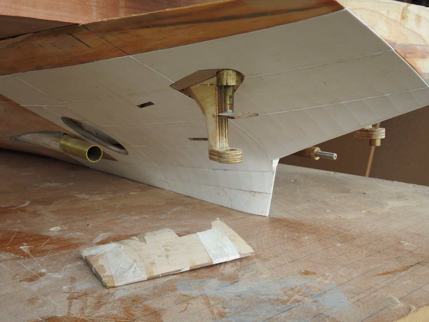
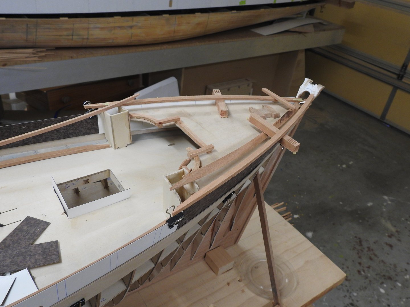
The most difficult plate in the whole model is on on one side. Deck removed to show mooring deck ready to be fitted with all the framing, the most complex bit of framing on the model, the rolled corner losses shape without the deck in lace, but will return once the framing is in place. there are 2 tranverse frames which I will fit but the longitudinals will be fitted to the deck so this can be framed out and painted before the deck gets glued down That concludes the non glazed plating on the port side upper hull and all steel decks, once sanded I will prime and weld bead.


- 454 replies
-
- 7
-
-
-
- Union Steamship Company
- Stepcraft 840
- (and 3 more)
-
Thanks John, it looks better once weld beads are on.
- 454 replies
-
- 1
-
-
- Union Steamship Company
- Stepcraft 840
- (and 3 more)
-
Some shots from this weekeneds run. I also did a long tutorial on how that plating is done in the appropriate section.


- 454 replies
-
- 6
-
-
-
- Union Steamship Company
- Stepcraft 840
- (and 3 more)
-
I don't think many of us are, but I for one want to at least get close, it's a very useful skill. At least it's cheap to learn and if things go wrong you can have another go, also I like the idea of being able to work on top of a paper plan with a sheet of celluloid or glass so you have a guide. Thats why we need a movement to get her videos back she put up 10 years ago. I have spent nearly a day looking through the web for links to it ,mainly on Czech sites and sent private messages asking when I find contact links, but sadly she has not been in here since 2021
-
I recently added Photoetching to my skillset, it took me 2 years to get around to it and I think i worked it up into something scary in my mind but it's really not, but for gingerbread at your scale I dont think it would cut it and you can't get the bevelled forms, everything has to be flat or inset Doris, if you are watching this can you please link us back to your vidoes on your incredible sculpting.
-
I have added step by step images now from todays session
-
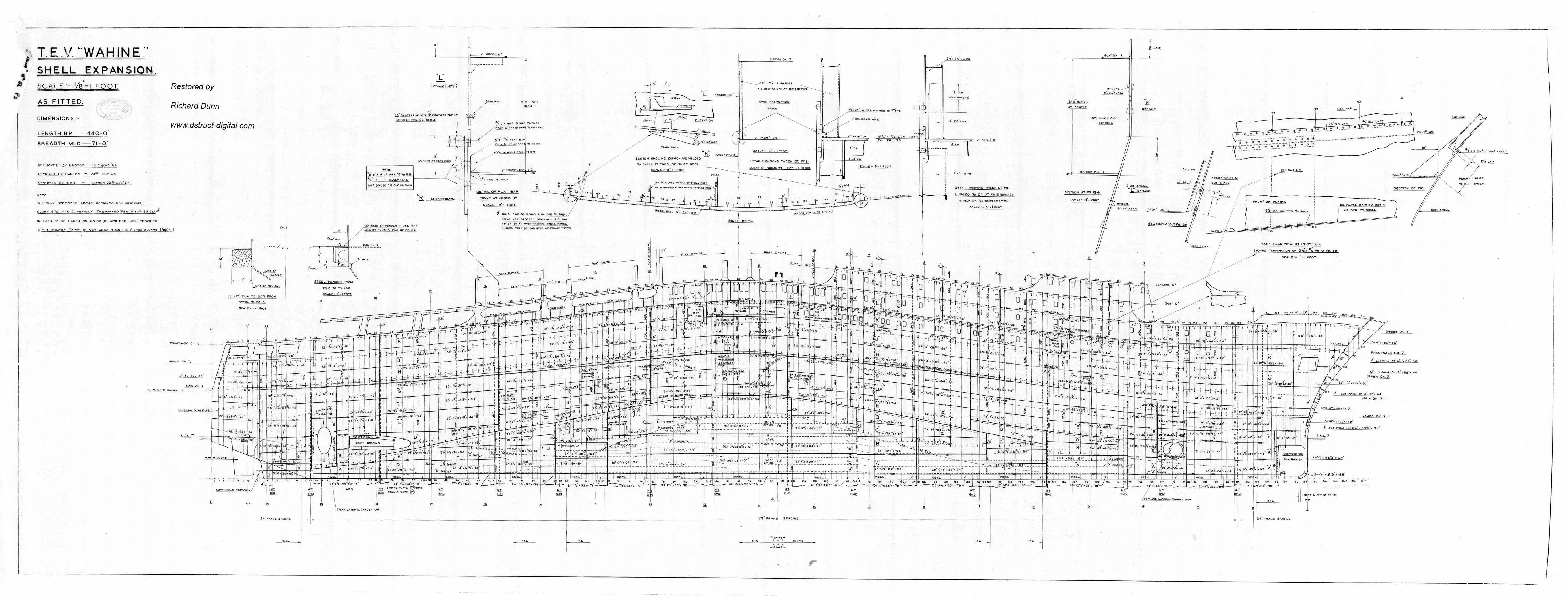
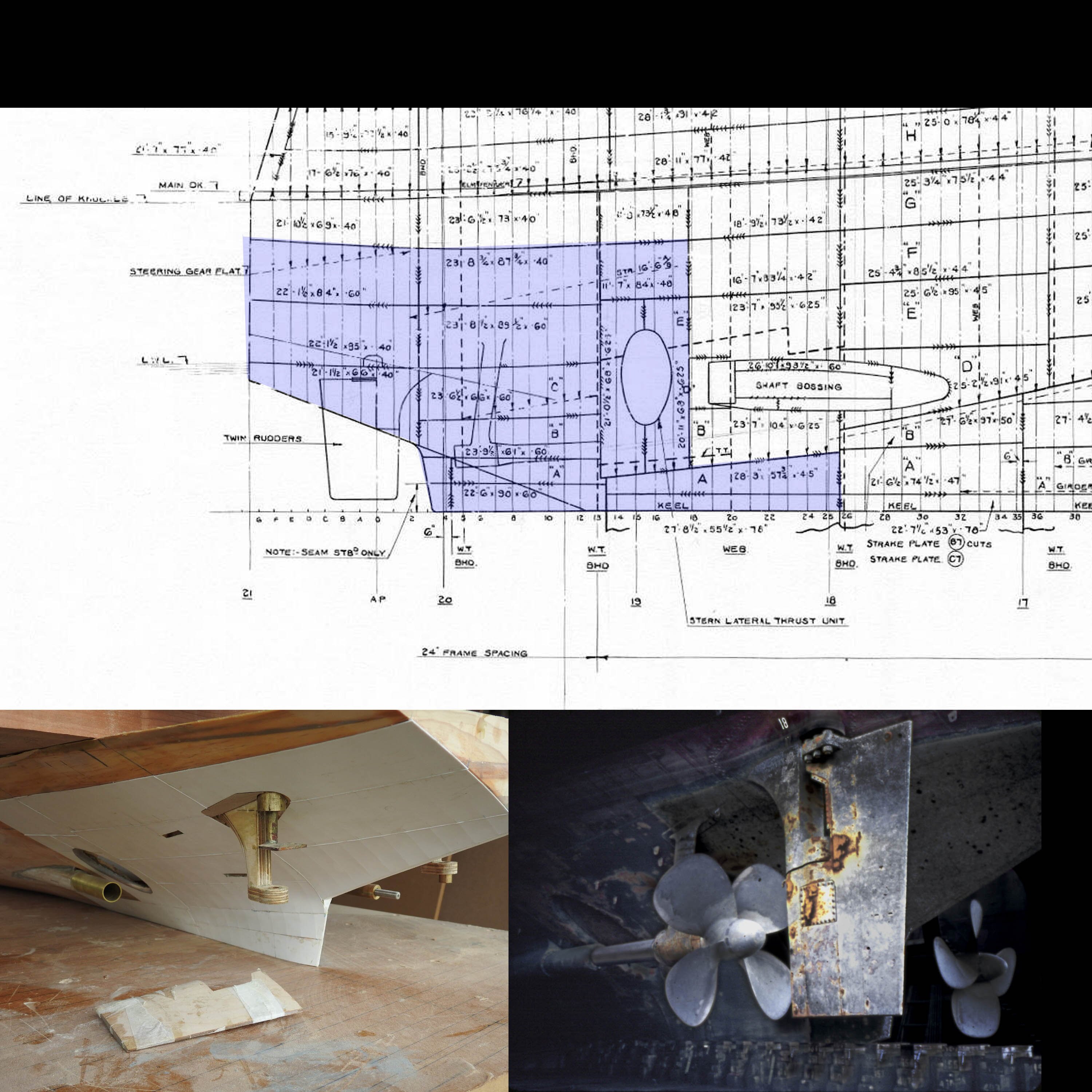
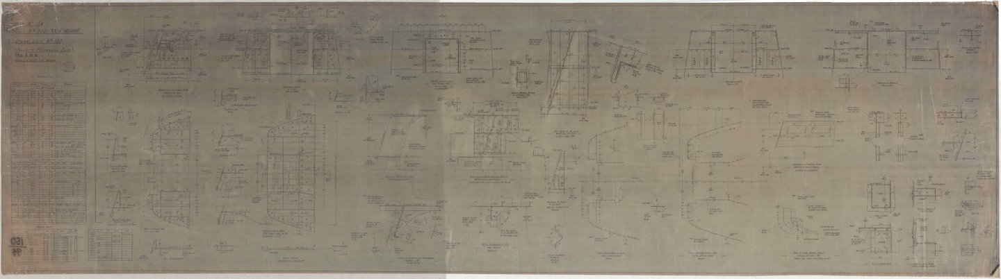
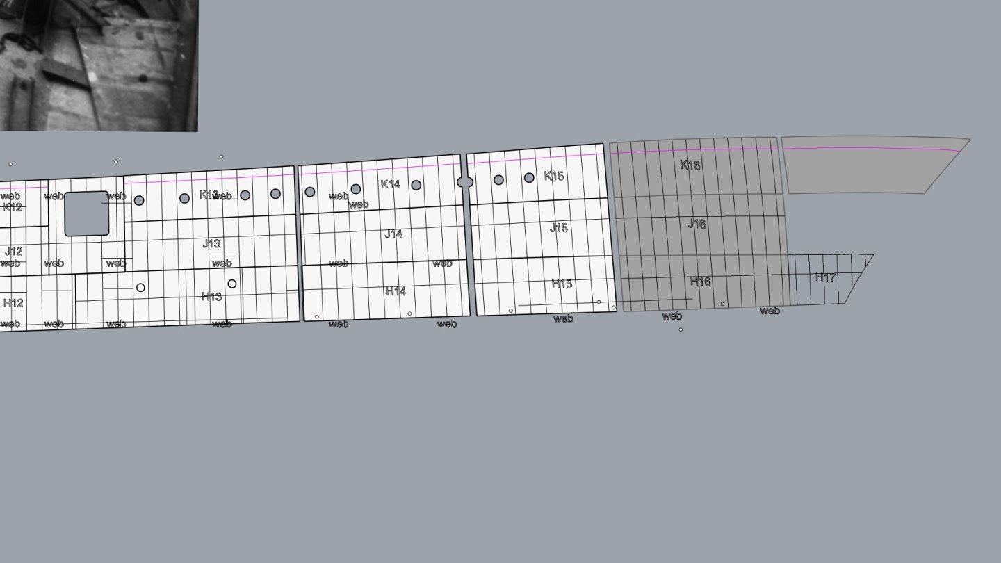
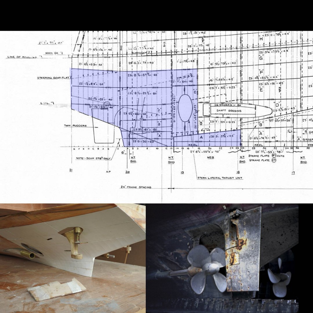
I should add that if you are lucky enough to have a CNC and the ability to 3d model you can cut the plates on the CNC after the true shape is developed from the model, in Rhino use Squish or Unroll developable surface, I don't think Fusion has the ability, it only does sheet metal work or folds. just like the real ship, also the frame and structure lines can be marked on them with a pen attachment in the cnc. The cad side of things looks like this. Unless you have Rhino or Delftship Pro with plating add-on just mark it all on the hull as described above I wil also add the Shell Expansion for this ship model for those who have not seen one before. This plan is about as good as Shell Expansions get and it contains a lot of good information about joints, I am happy to provide the full res if you ask I should add if you do this you need to make sure your hull is exactly like the 3d model or the plates will not fit, because we use .5mm rod for seams we cannot have gaps over .4mm without having to fill. if you carve the hull from bread and butter that is even harder to acheive but with time it can be done just don't rush it. Some examples of carving accuracy.

-
Re the gingerbread work, if you are savy with 3d modelling you could always resin print them or get them printed, thats what I was going to do for the 1/40 Cutty Sark Kit I made earlier this year but clay sculpting just looks nicer and it's just a case of forming it with small tools and water and then baking in the oven. just he says.....just... I imagine it takes a bit of practice...
-
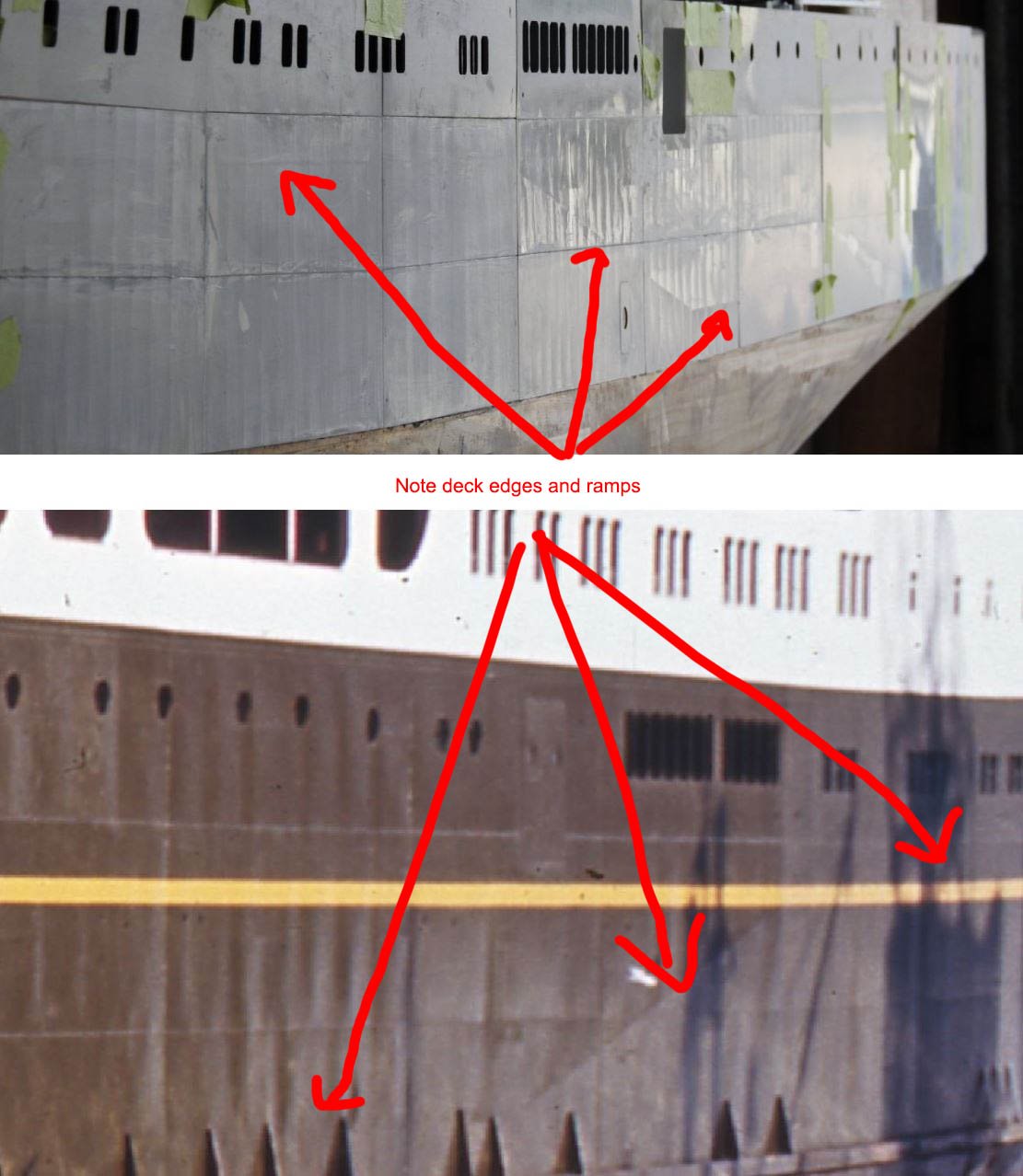
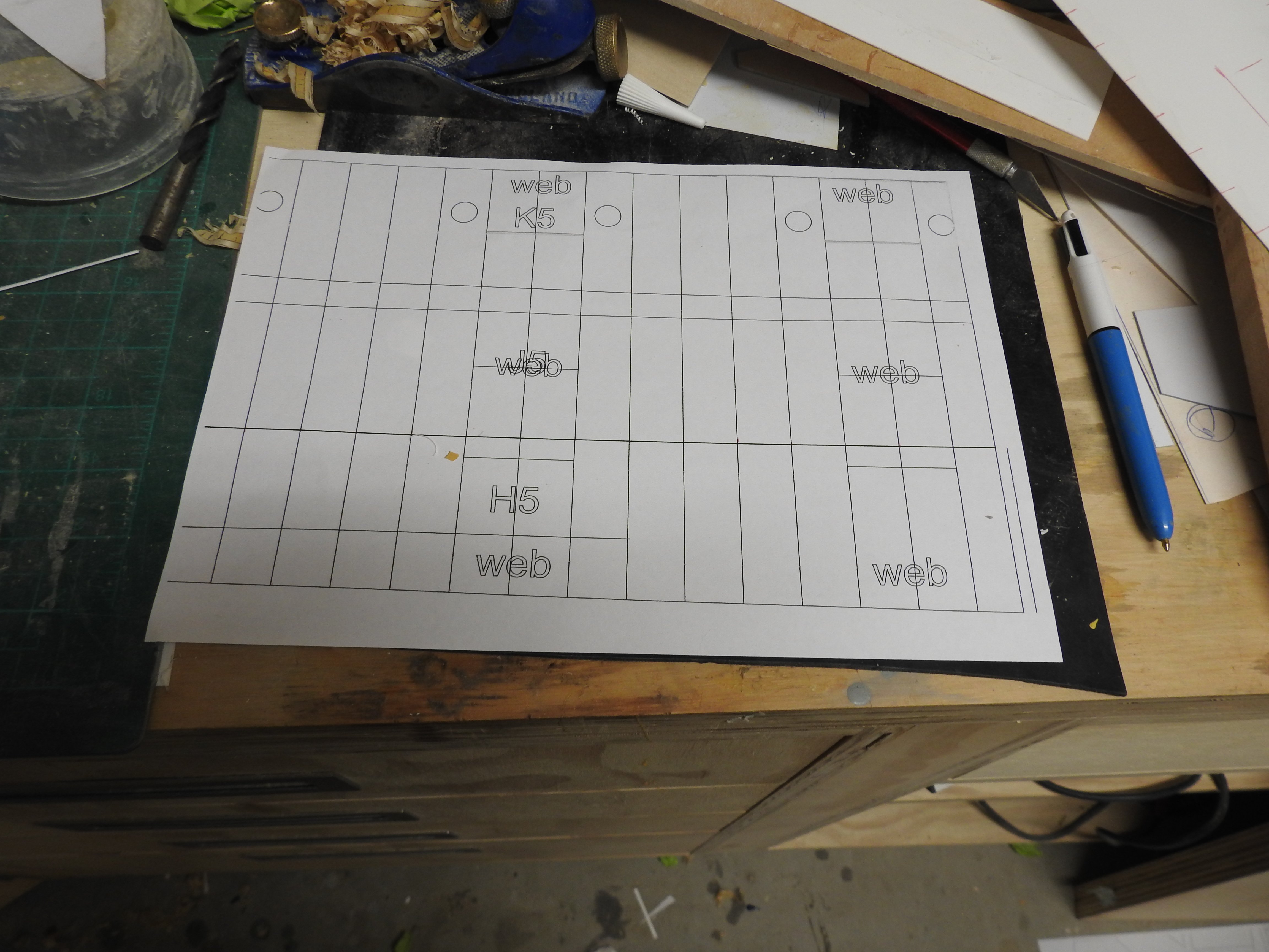
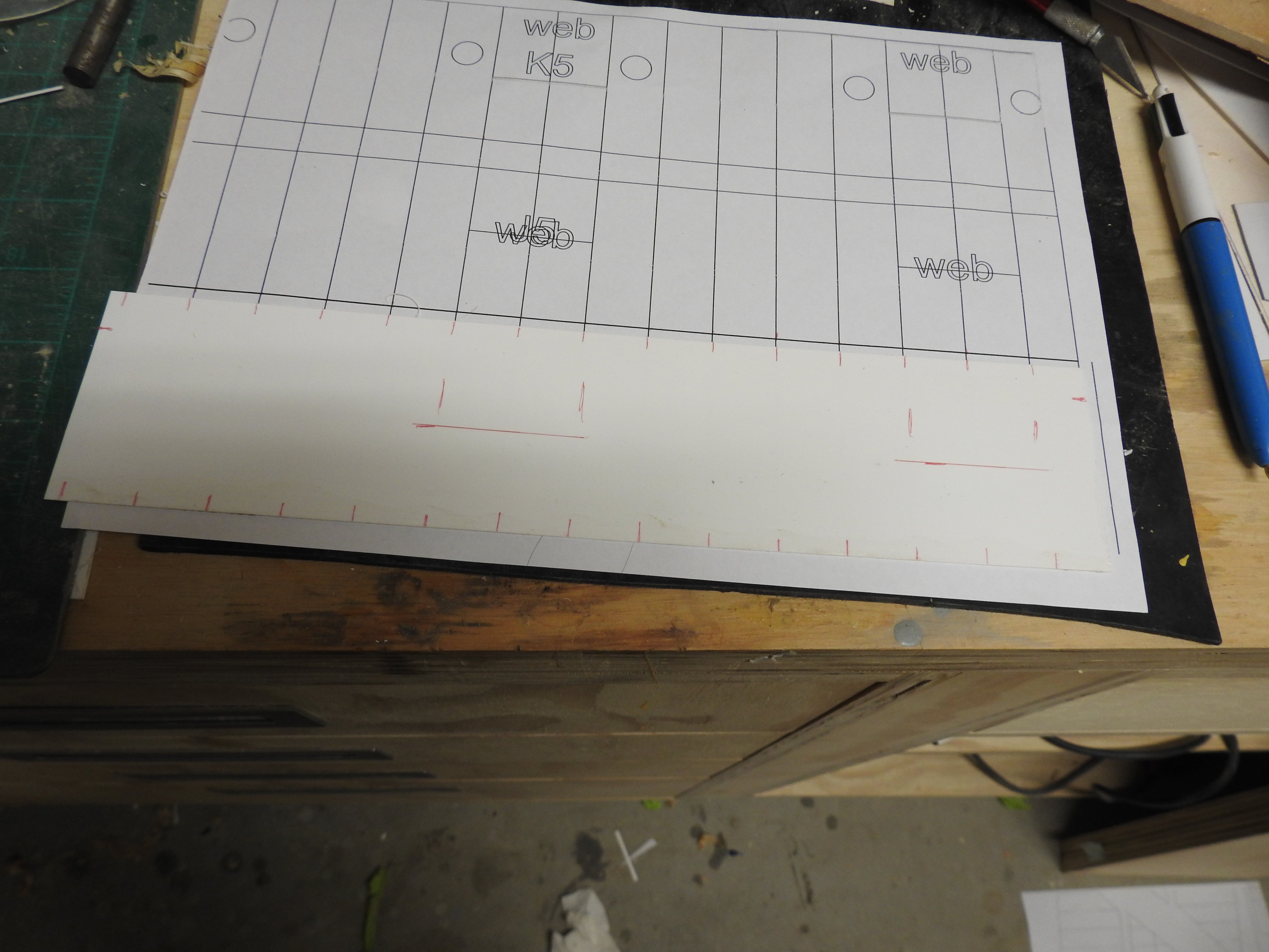
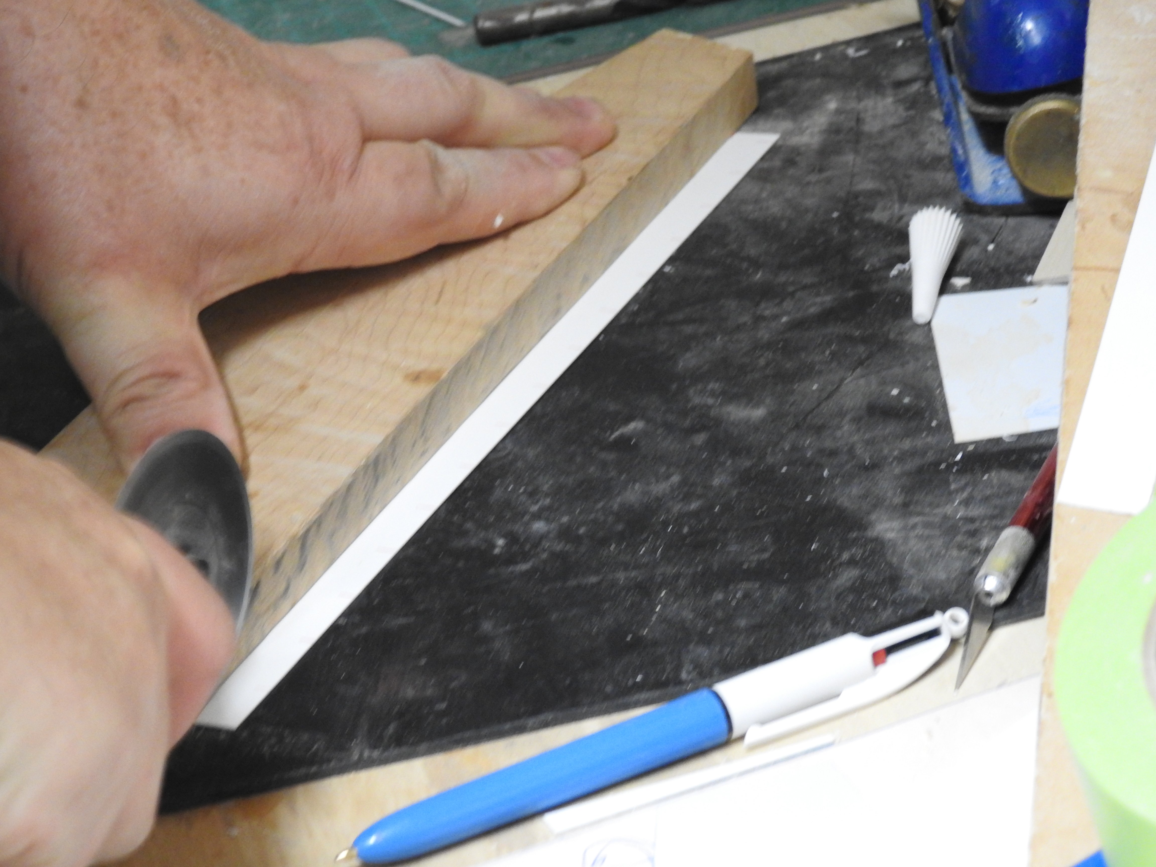
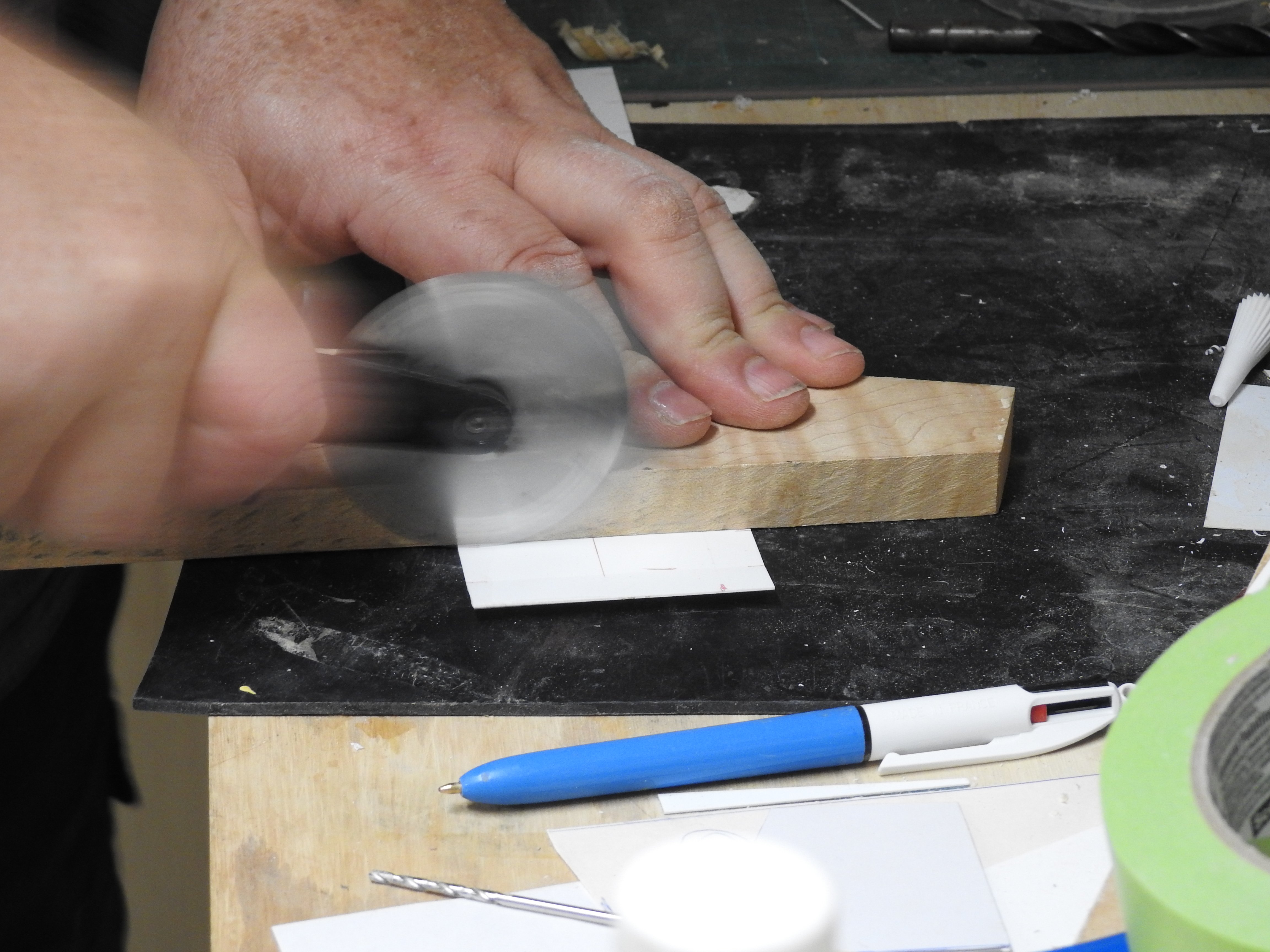
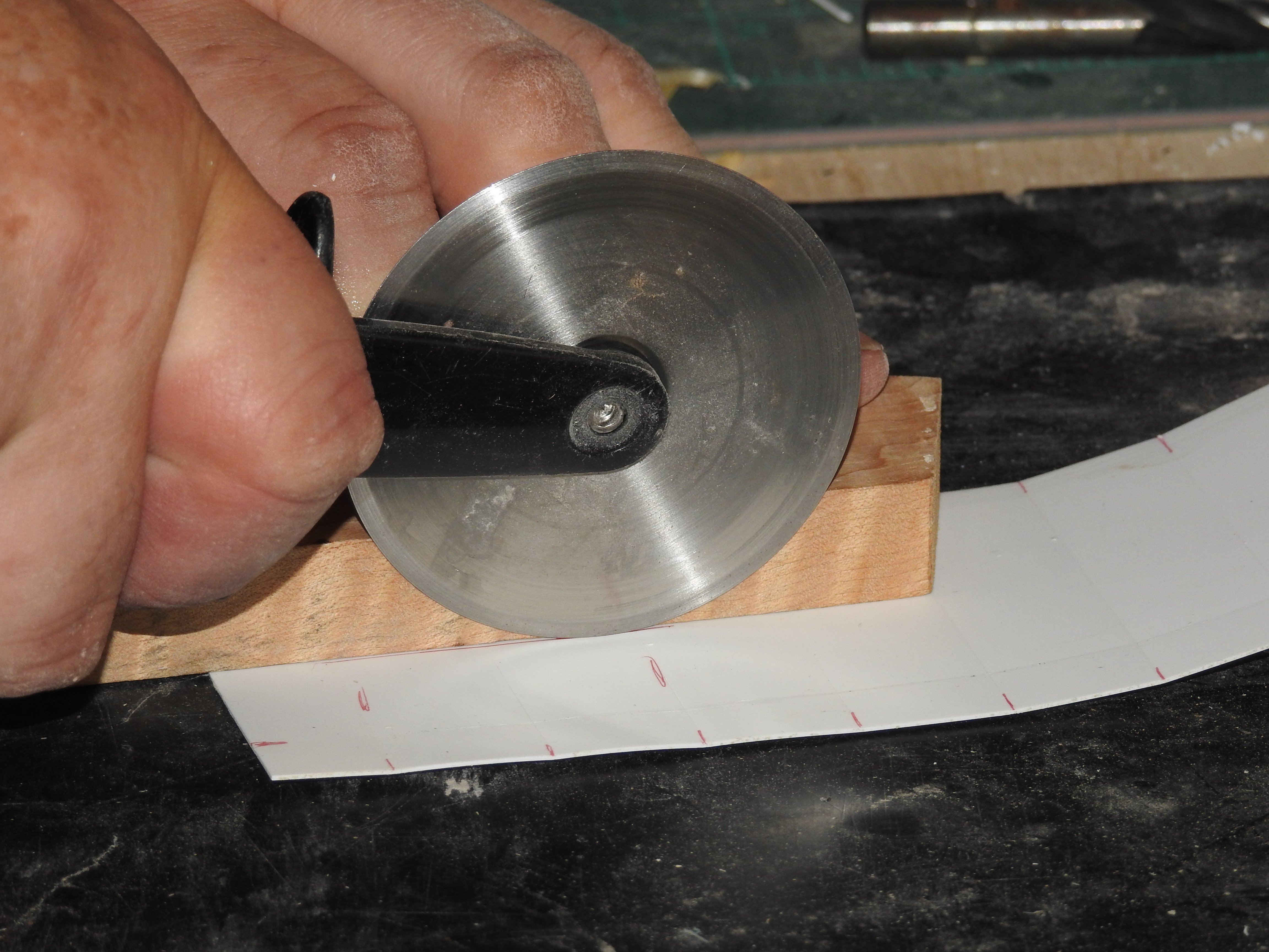
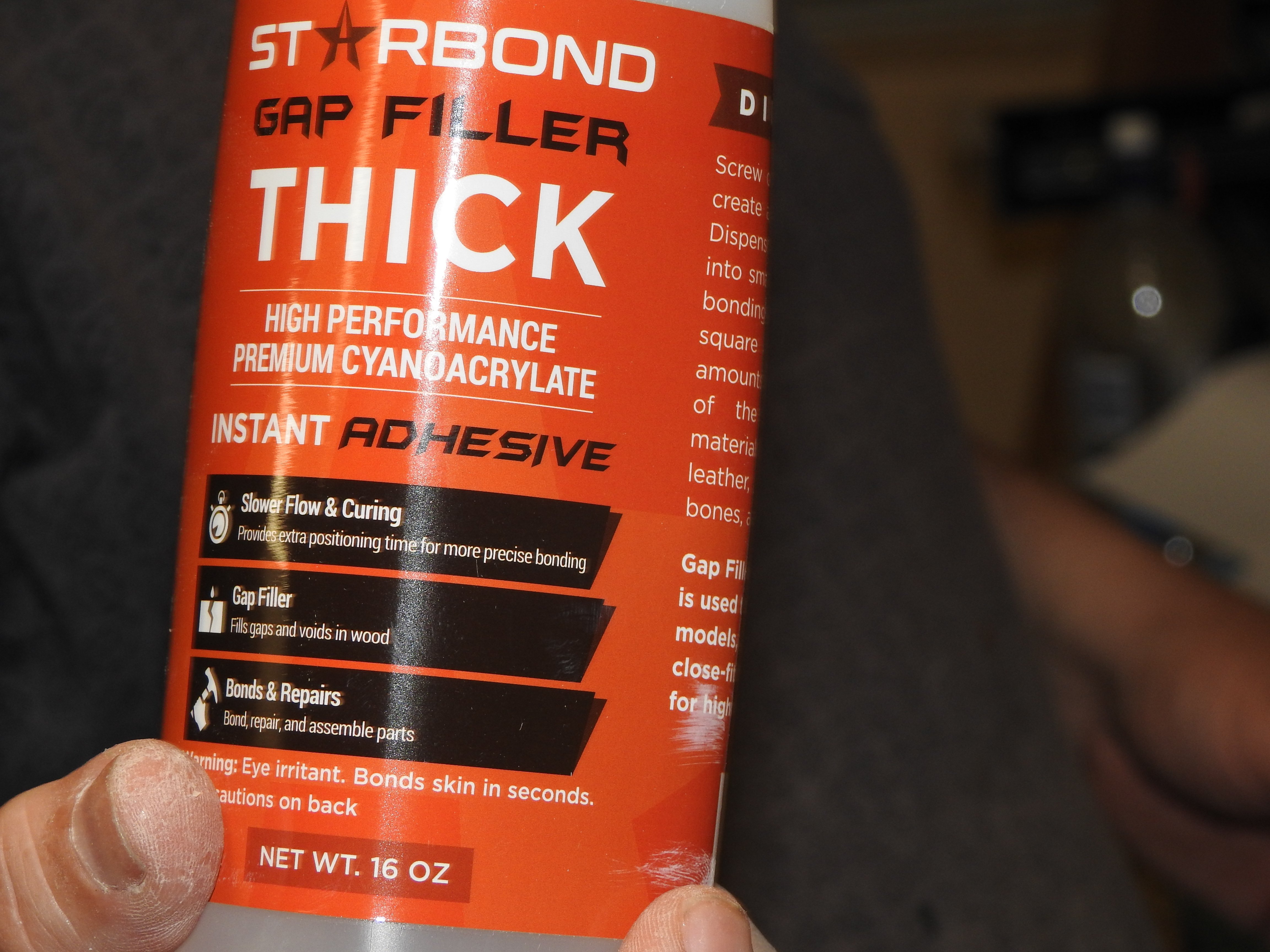
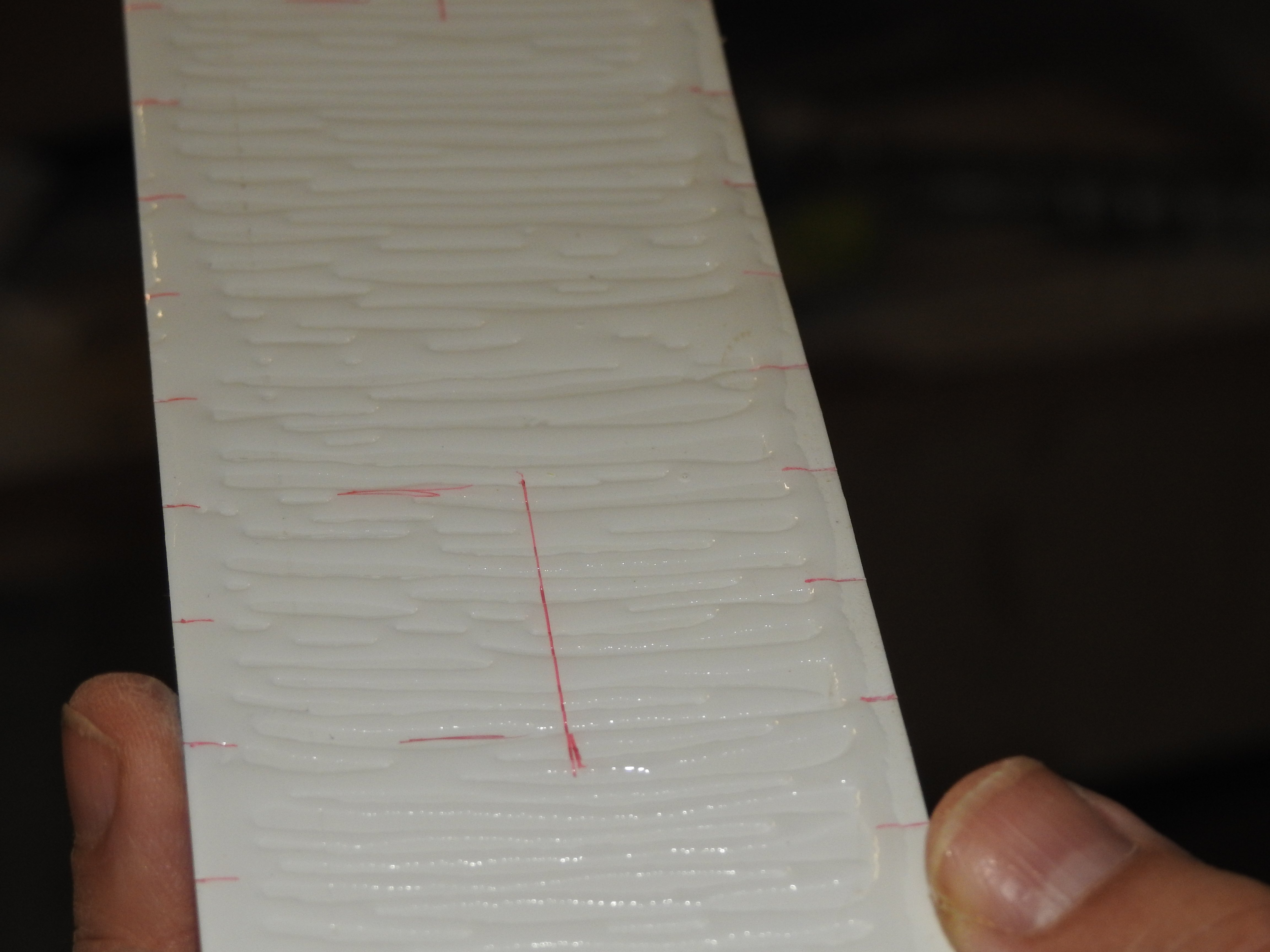
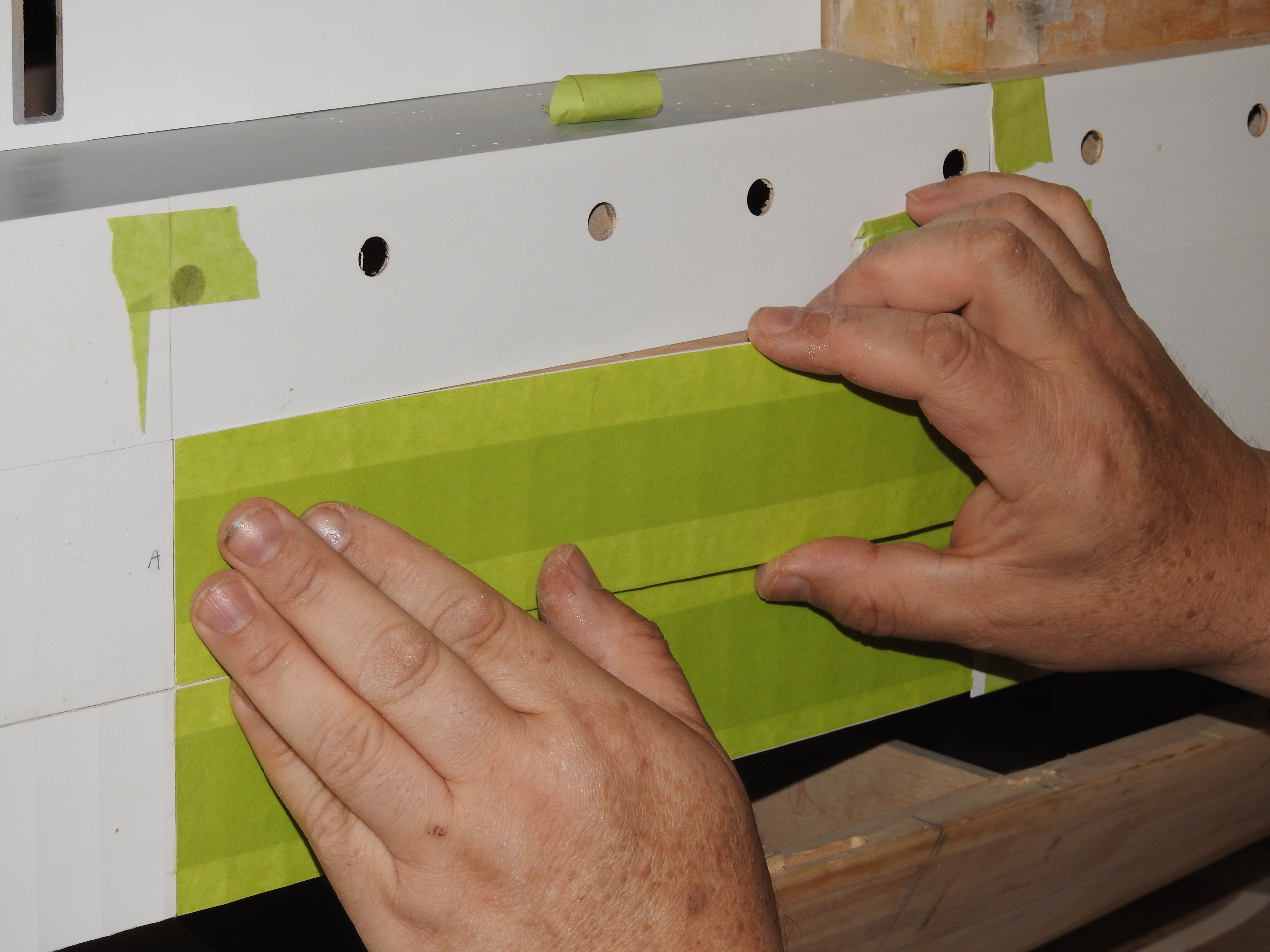
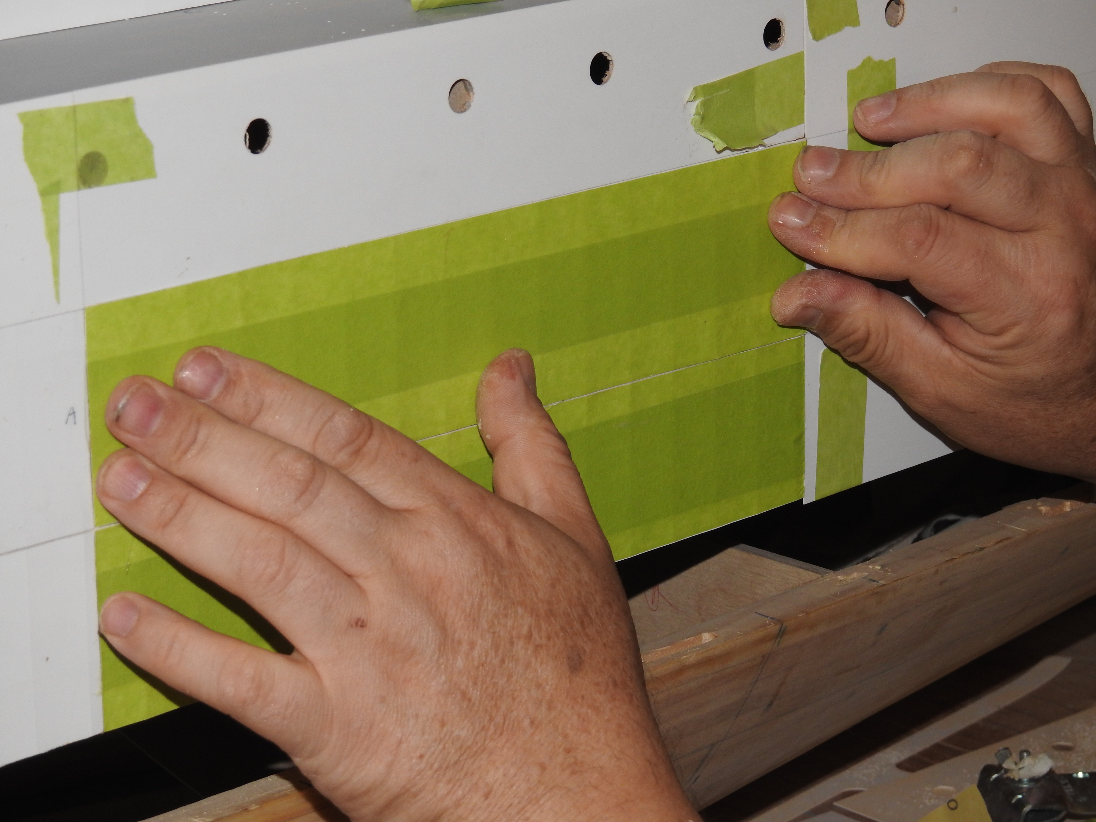
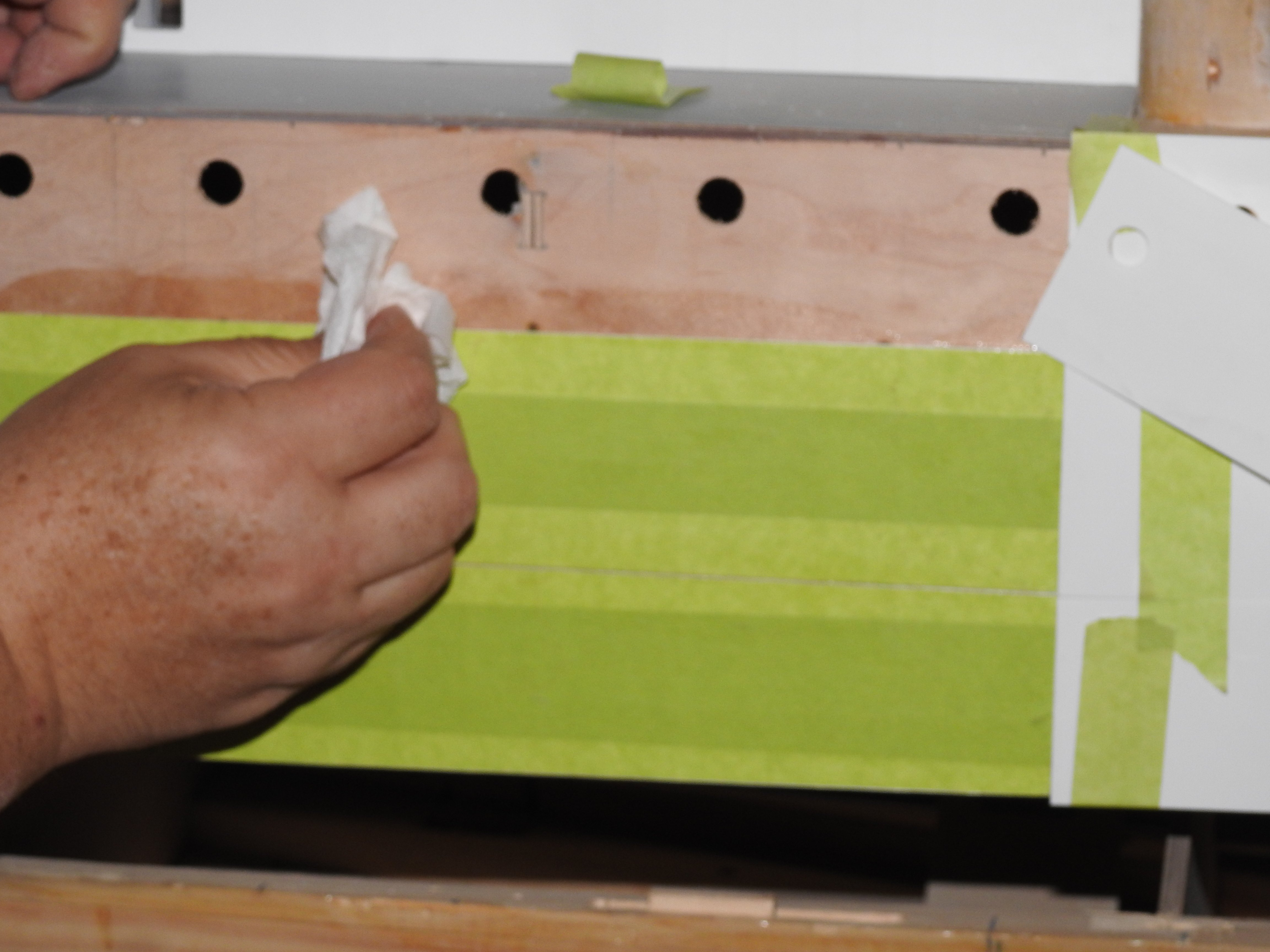
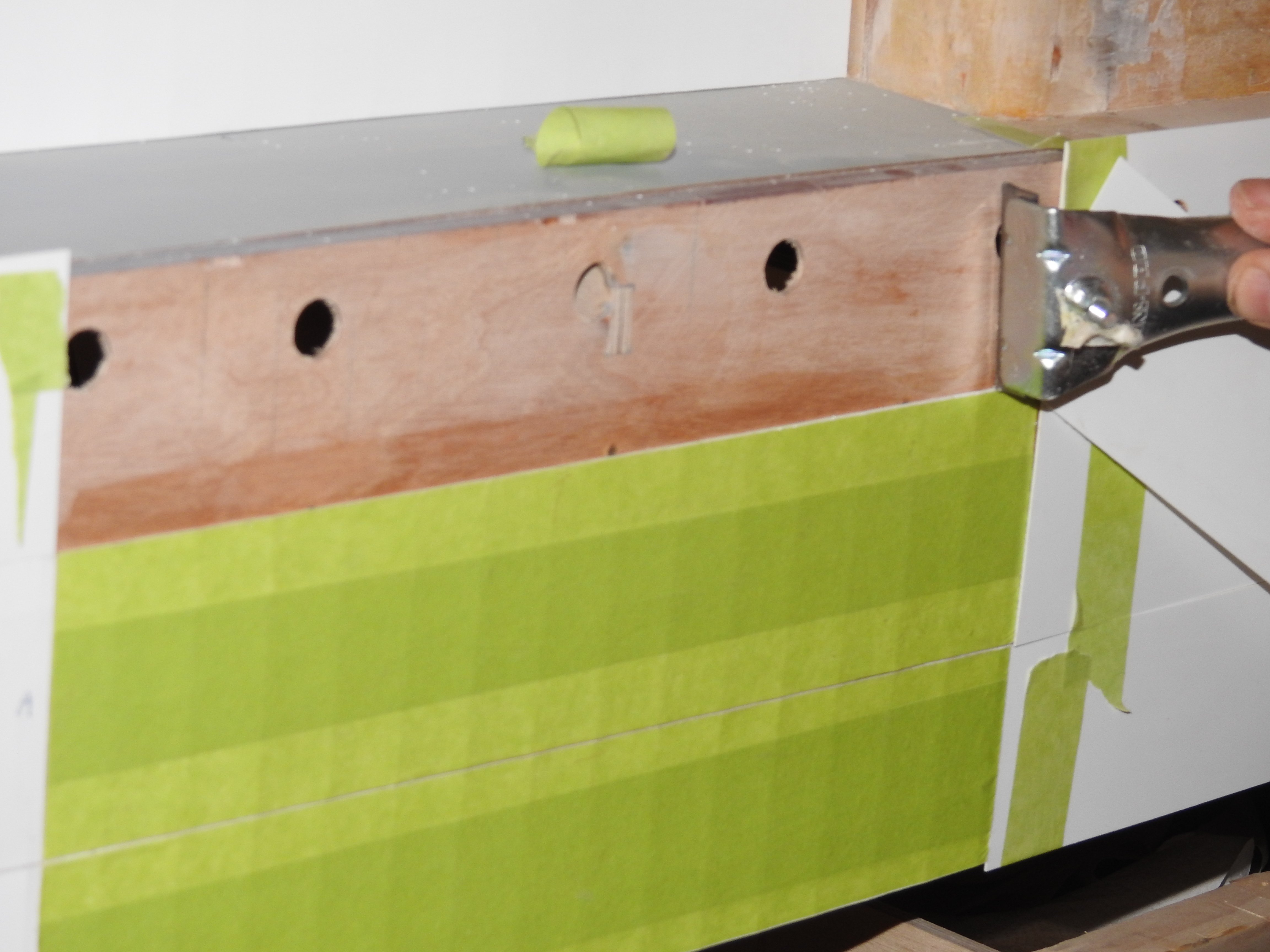
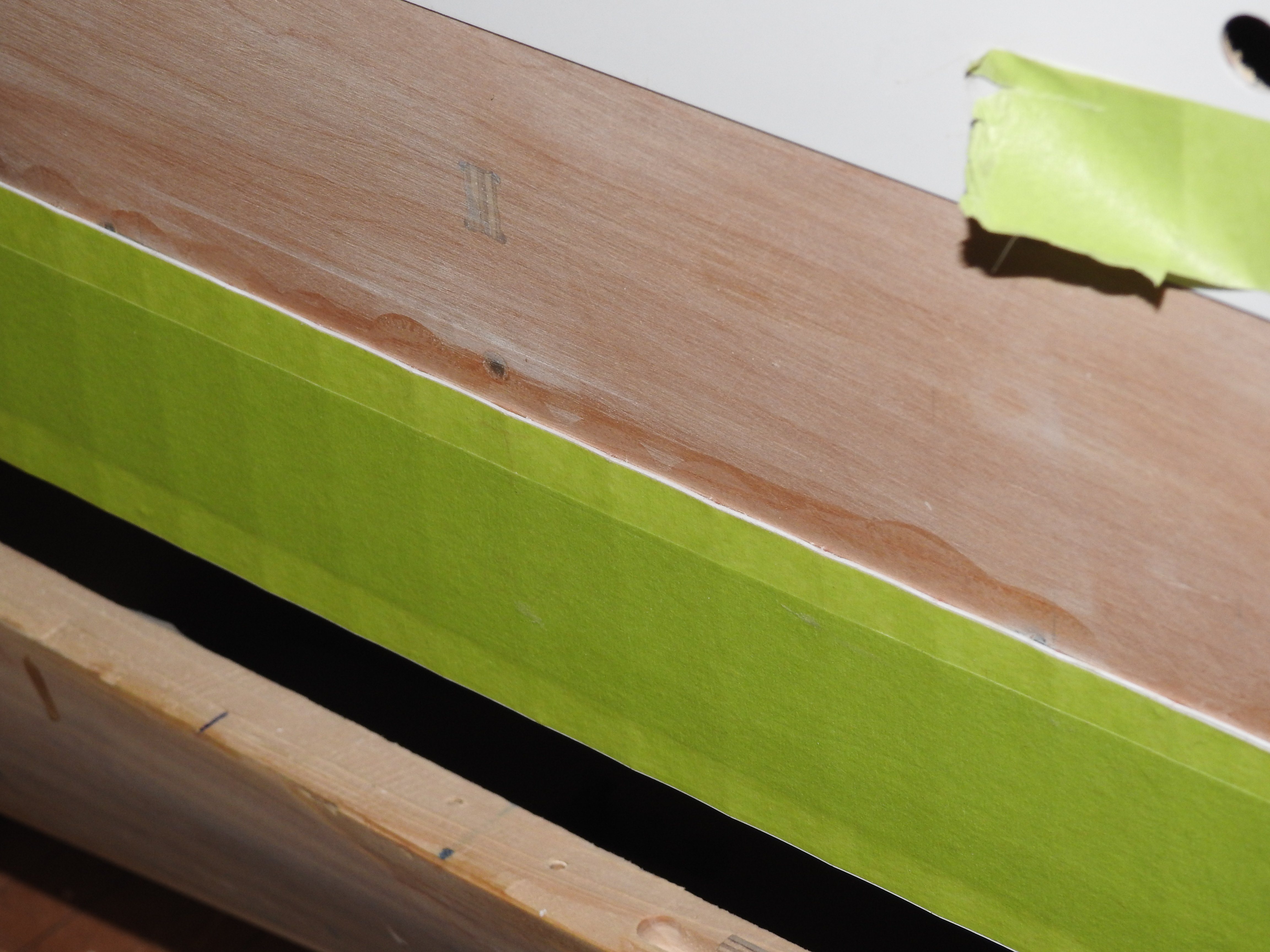
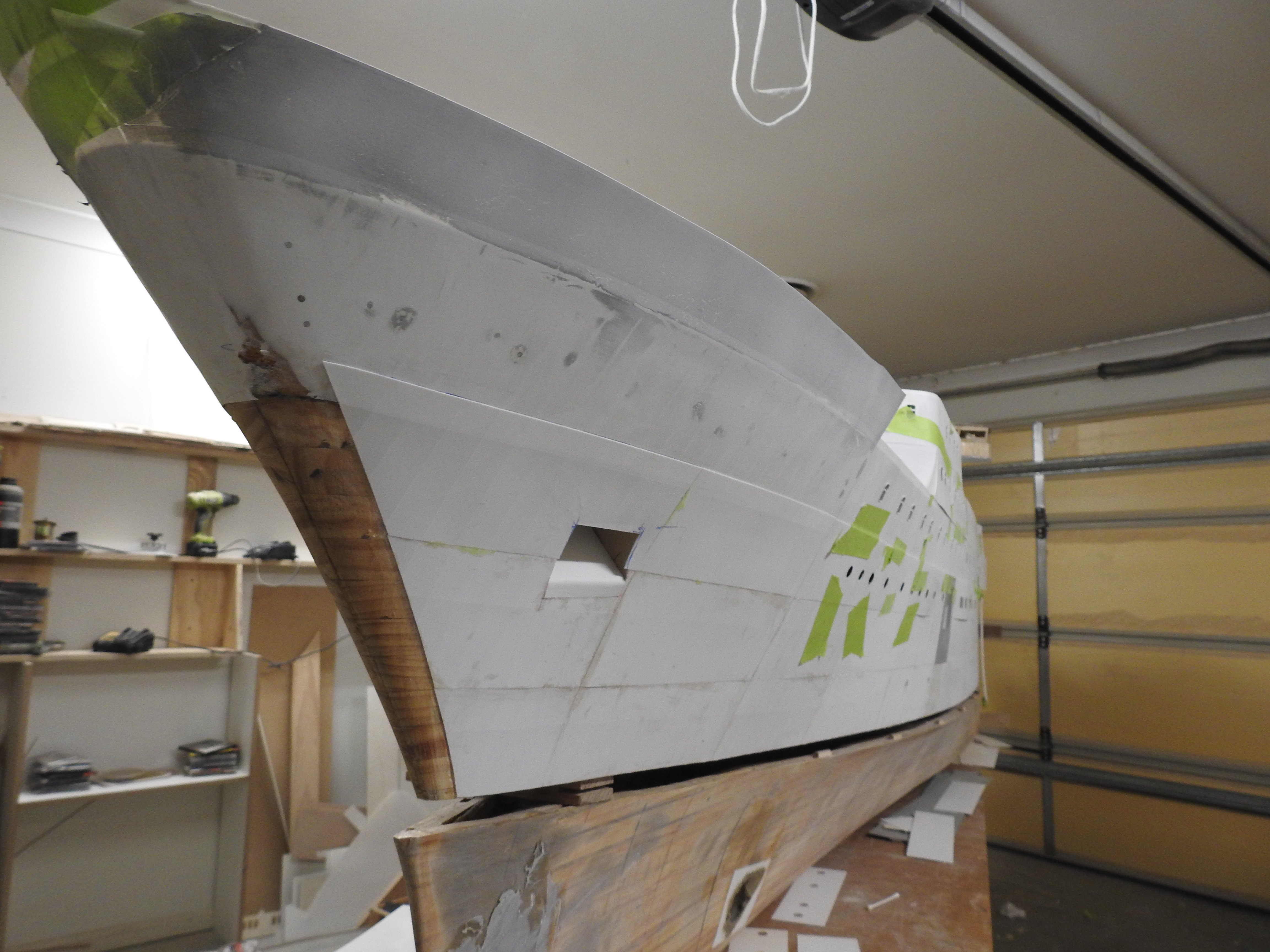
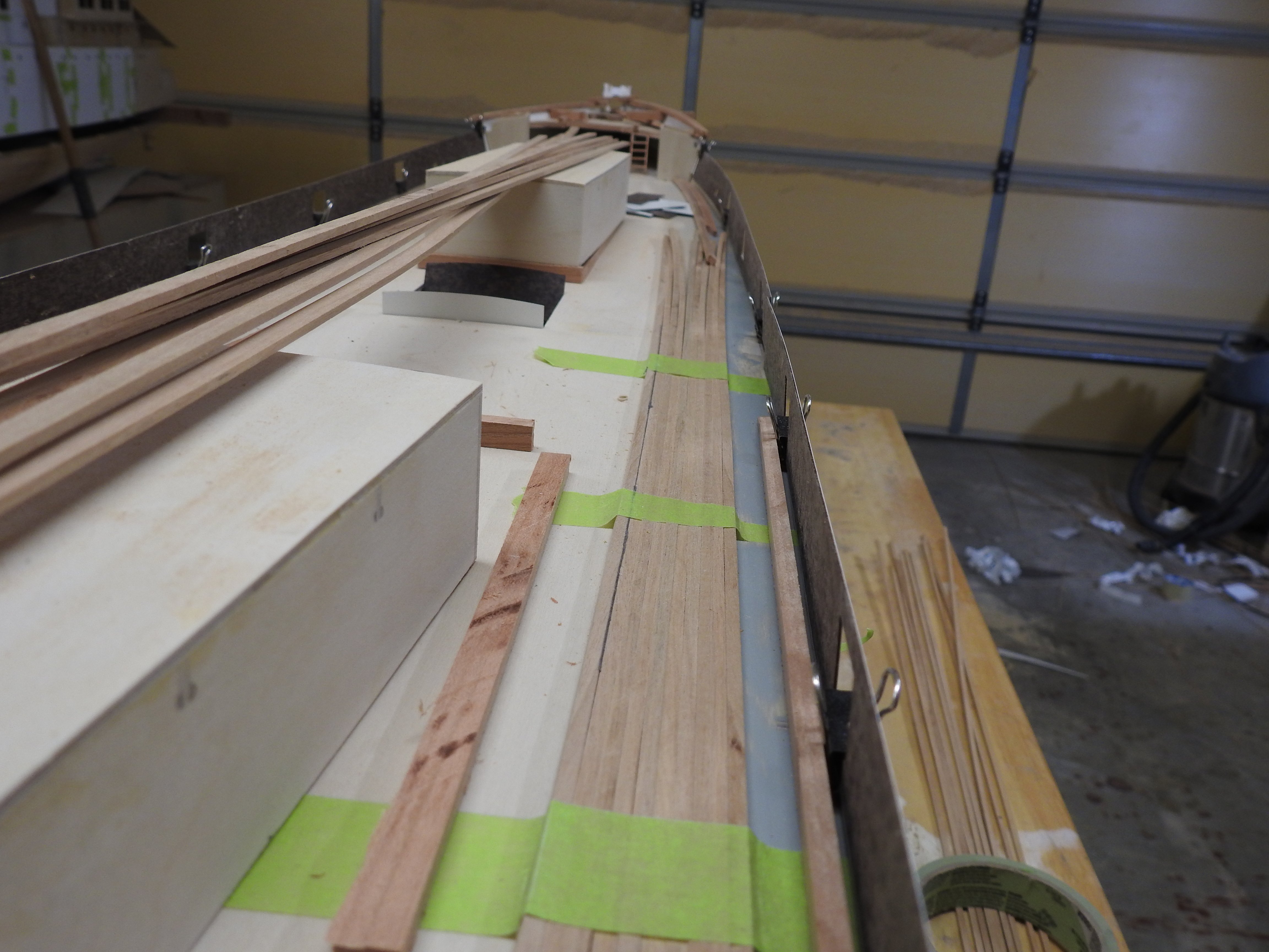
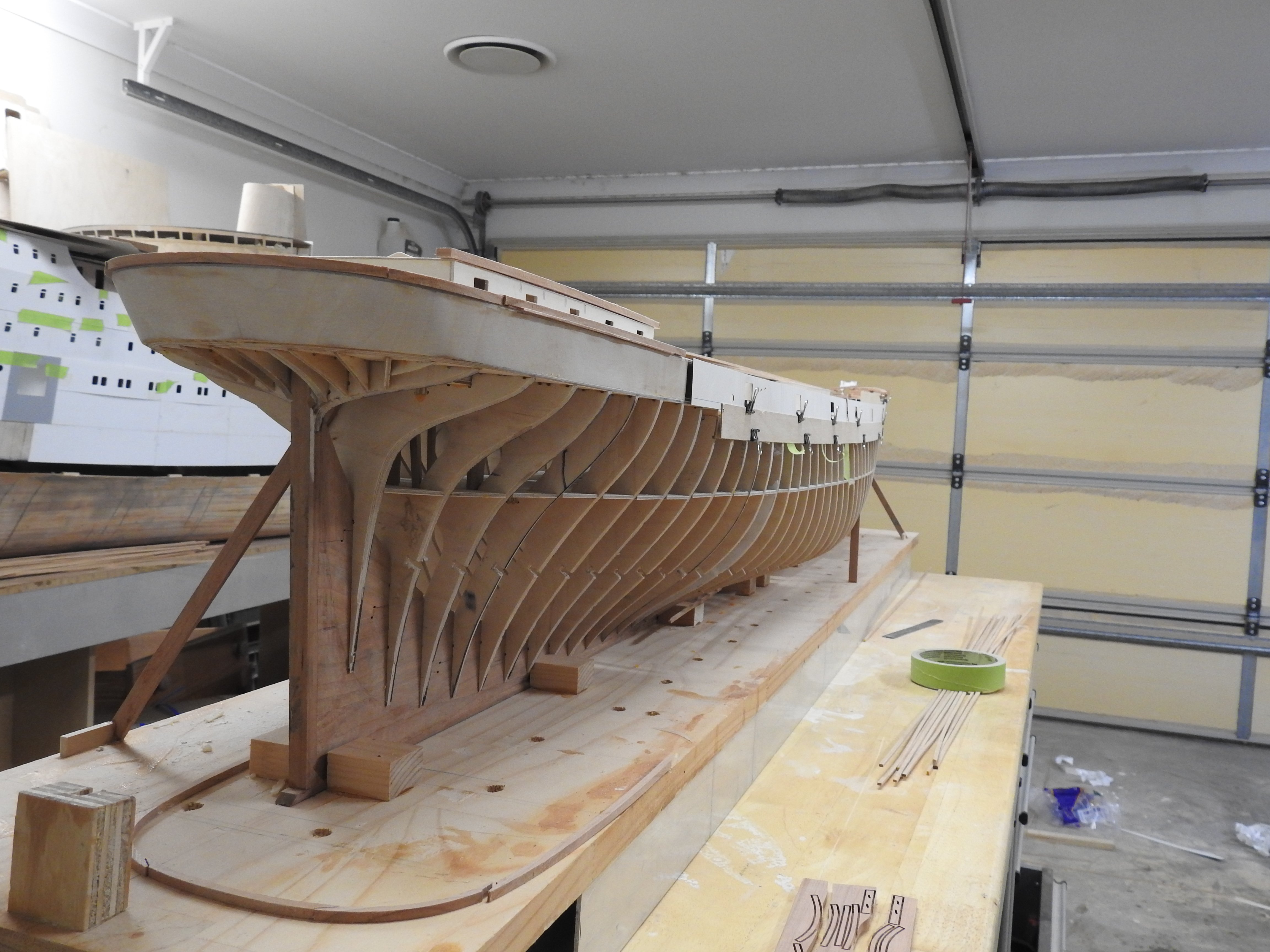
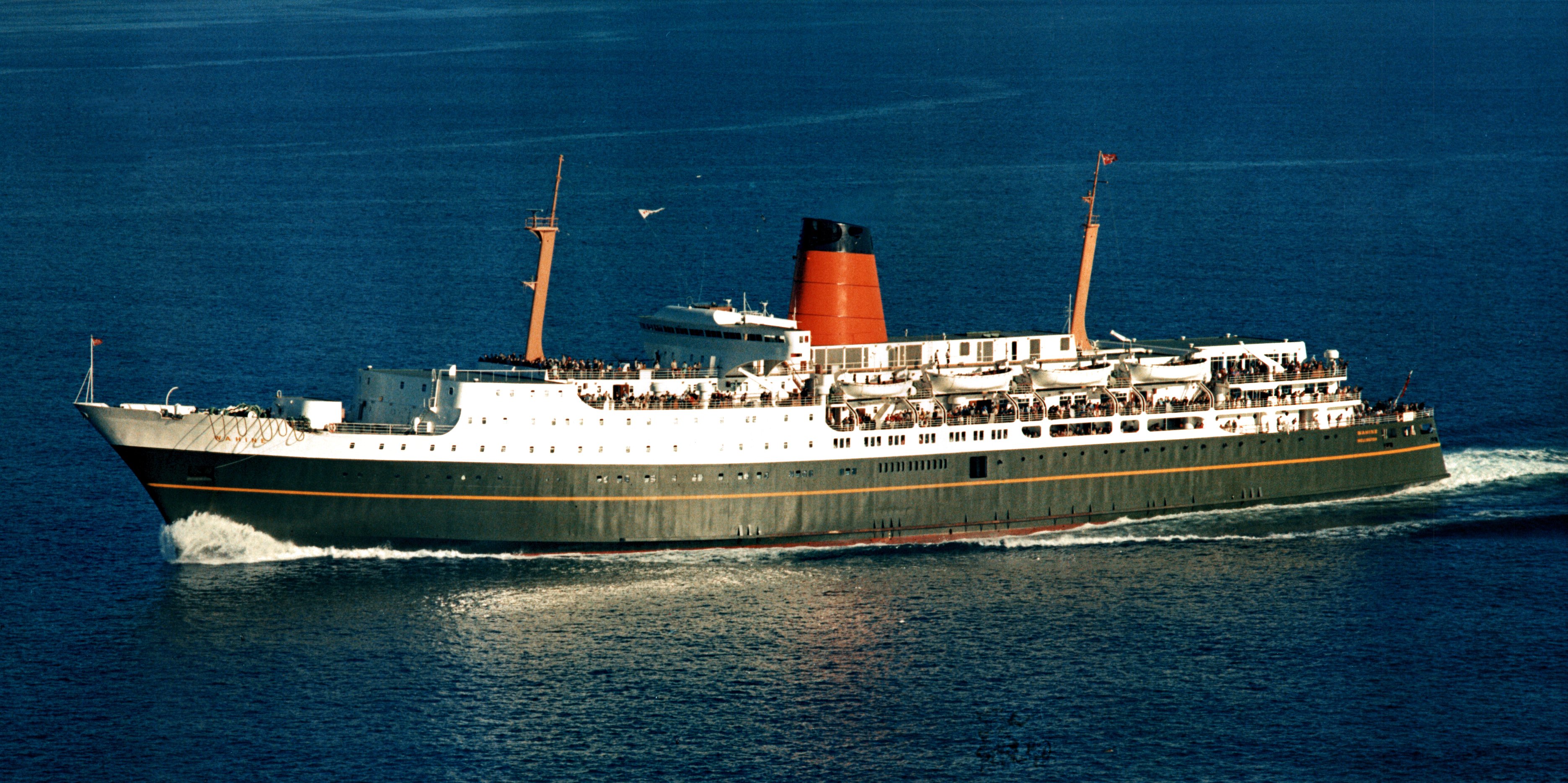
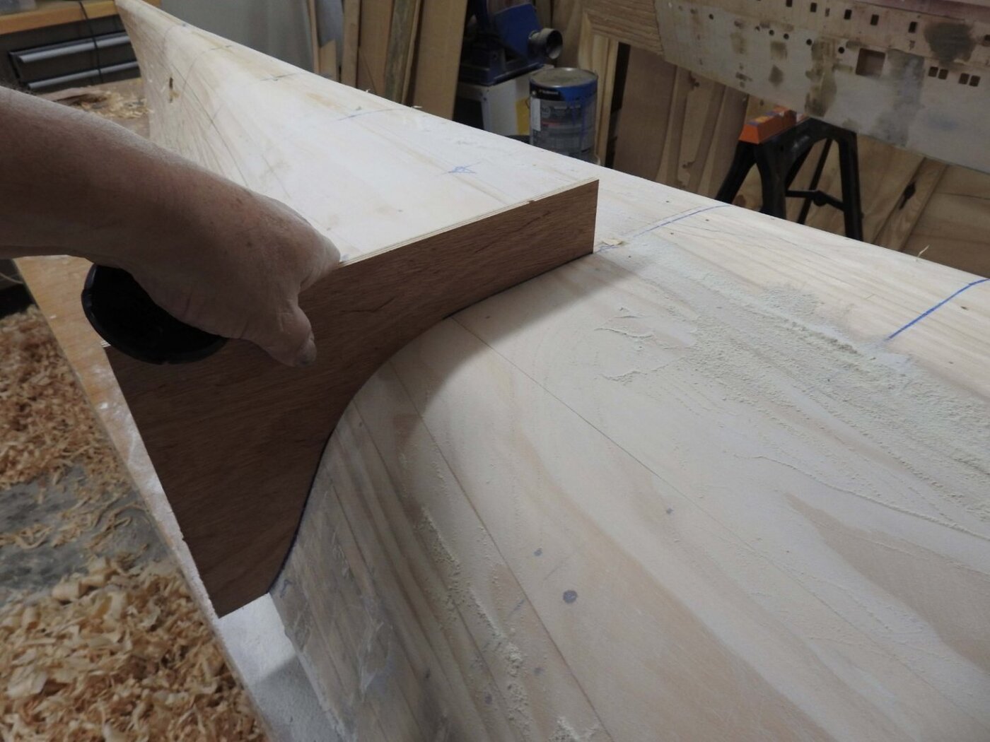
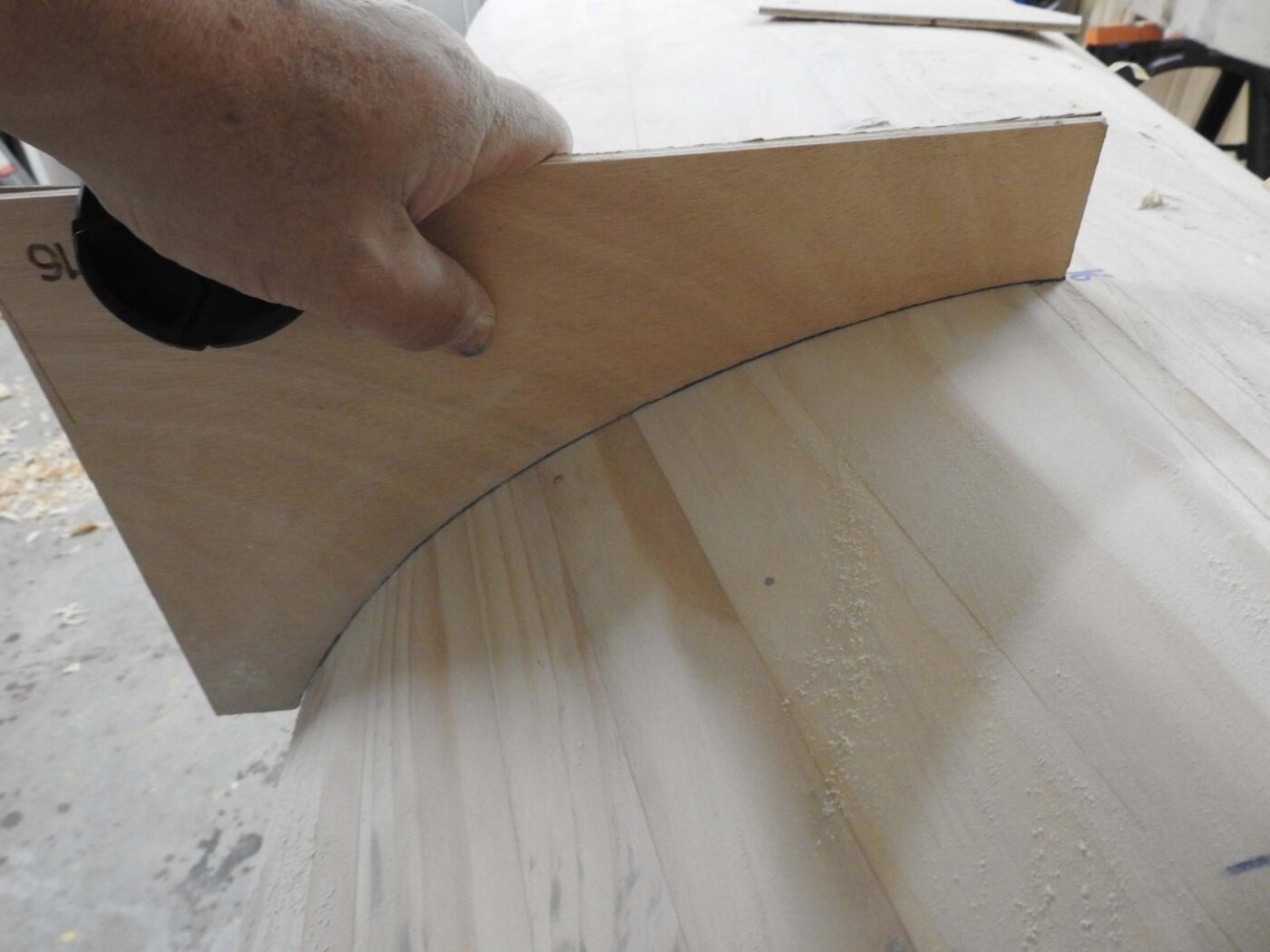
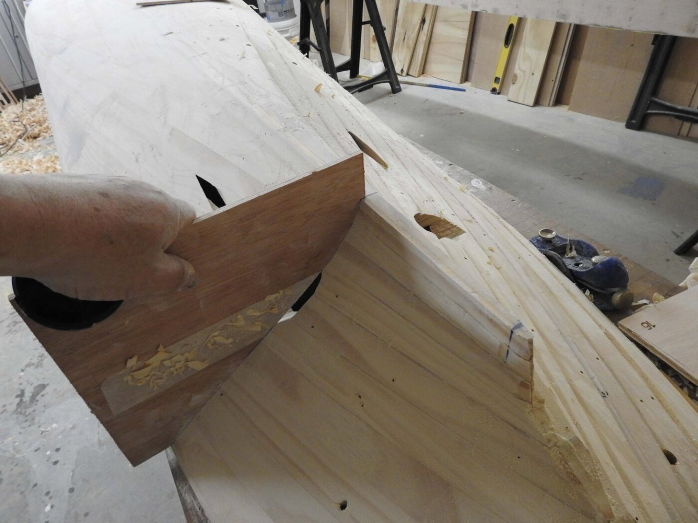
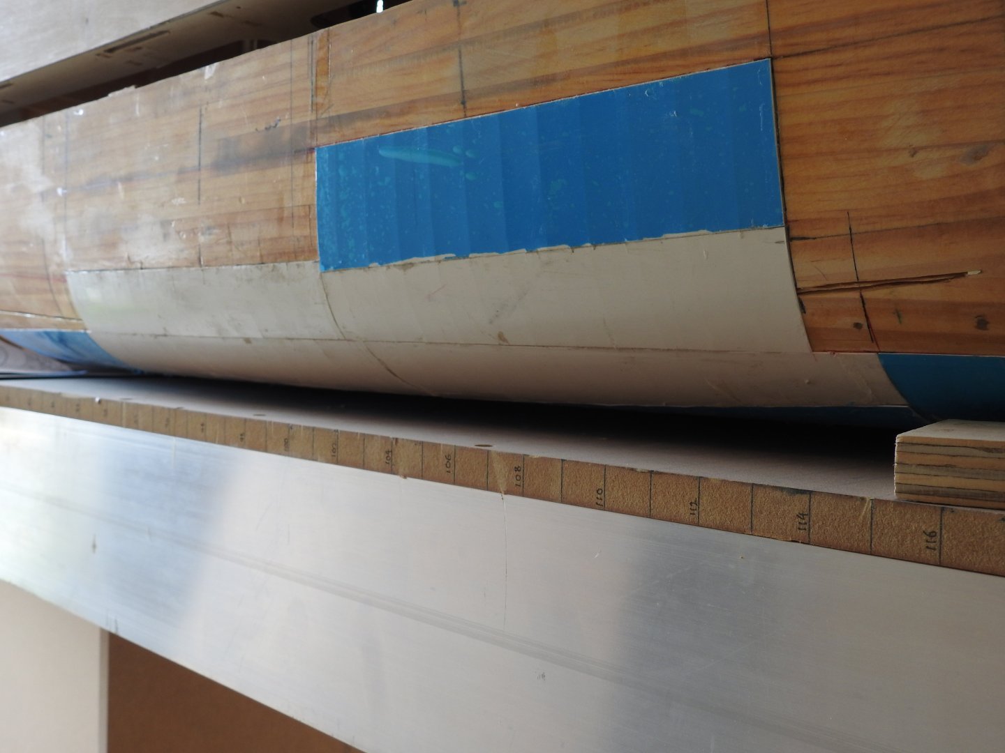
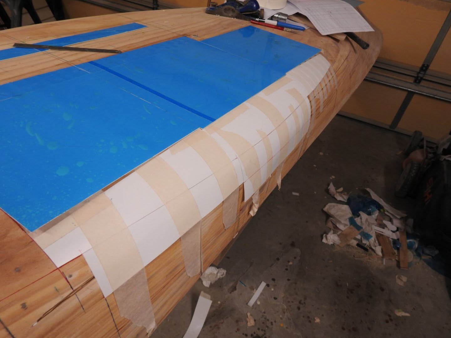
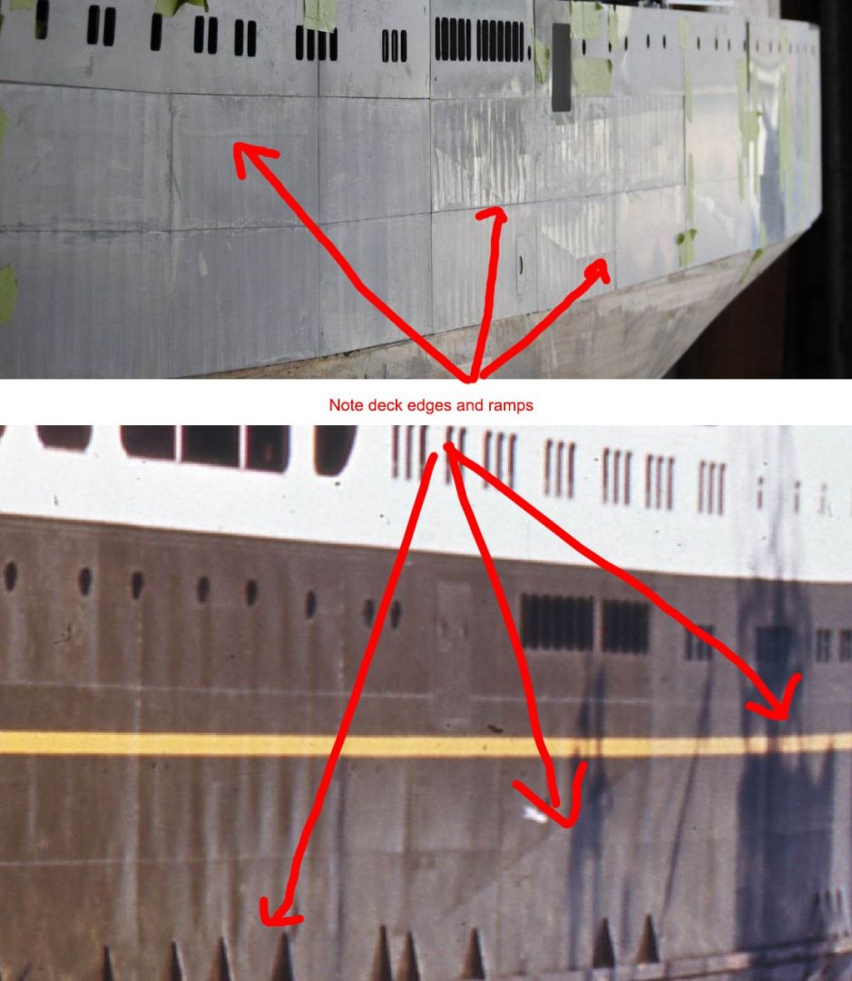
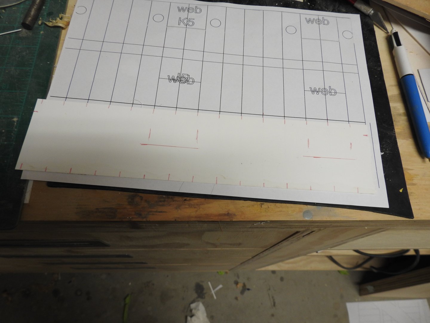
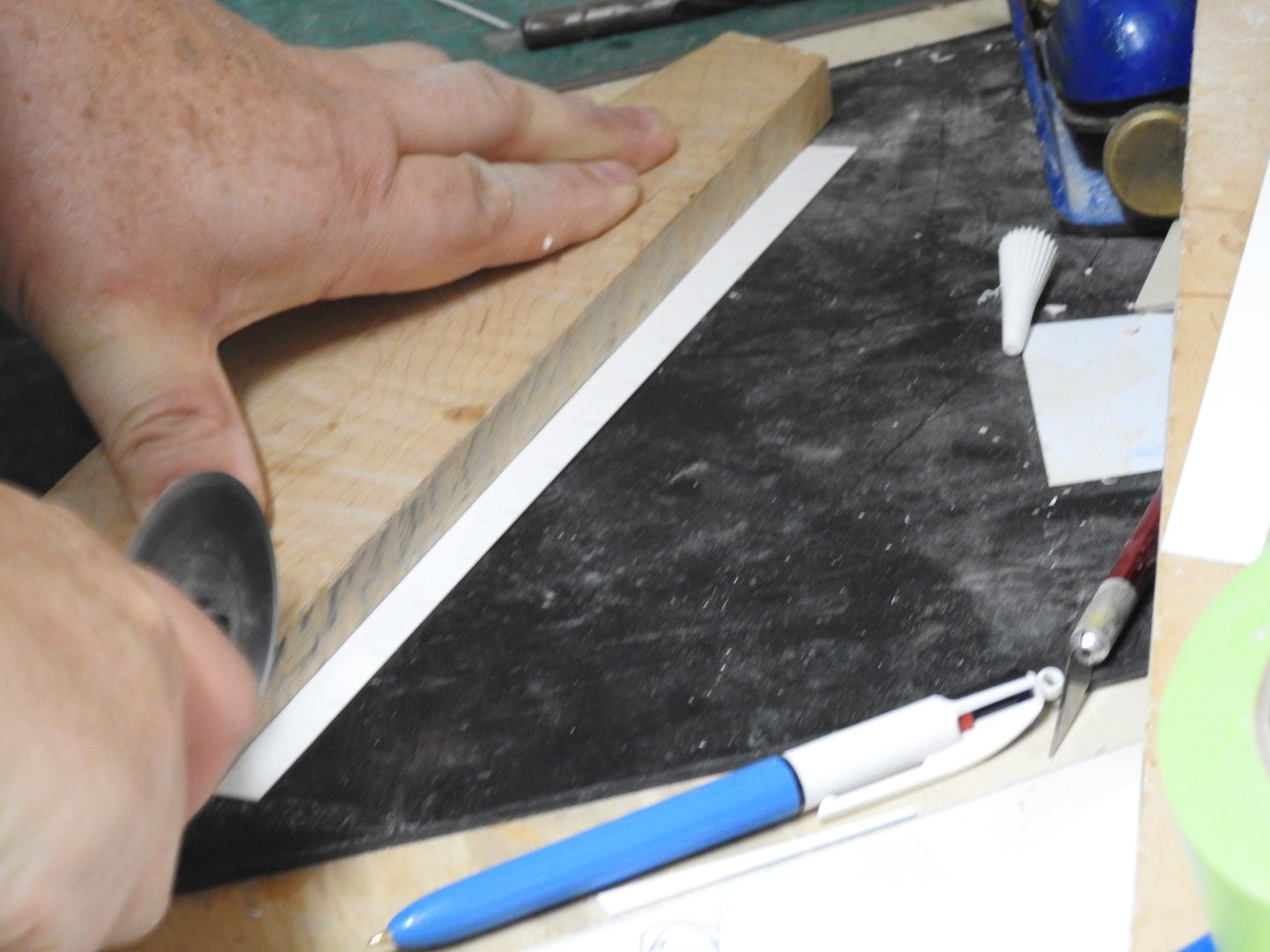
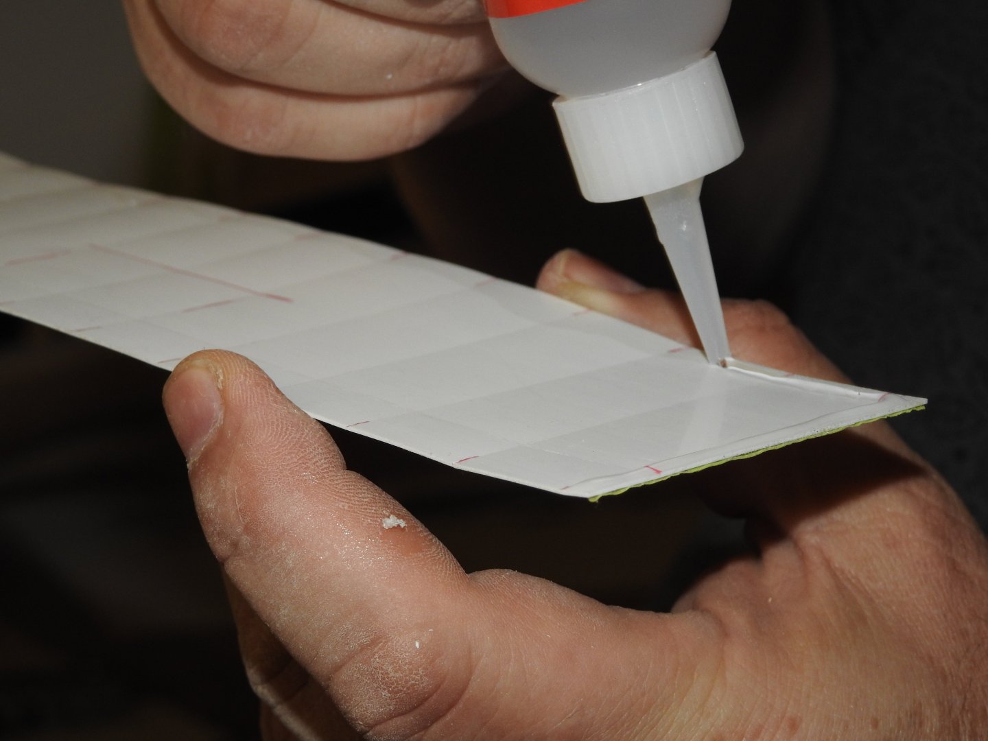
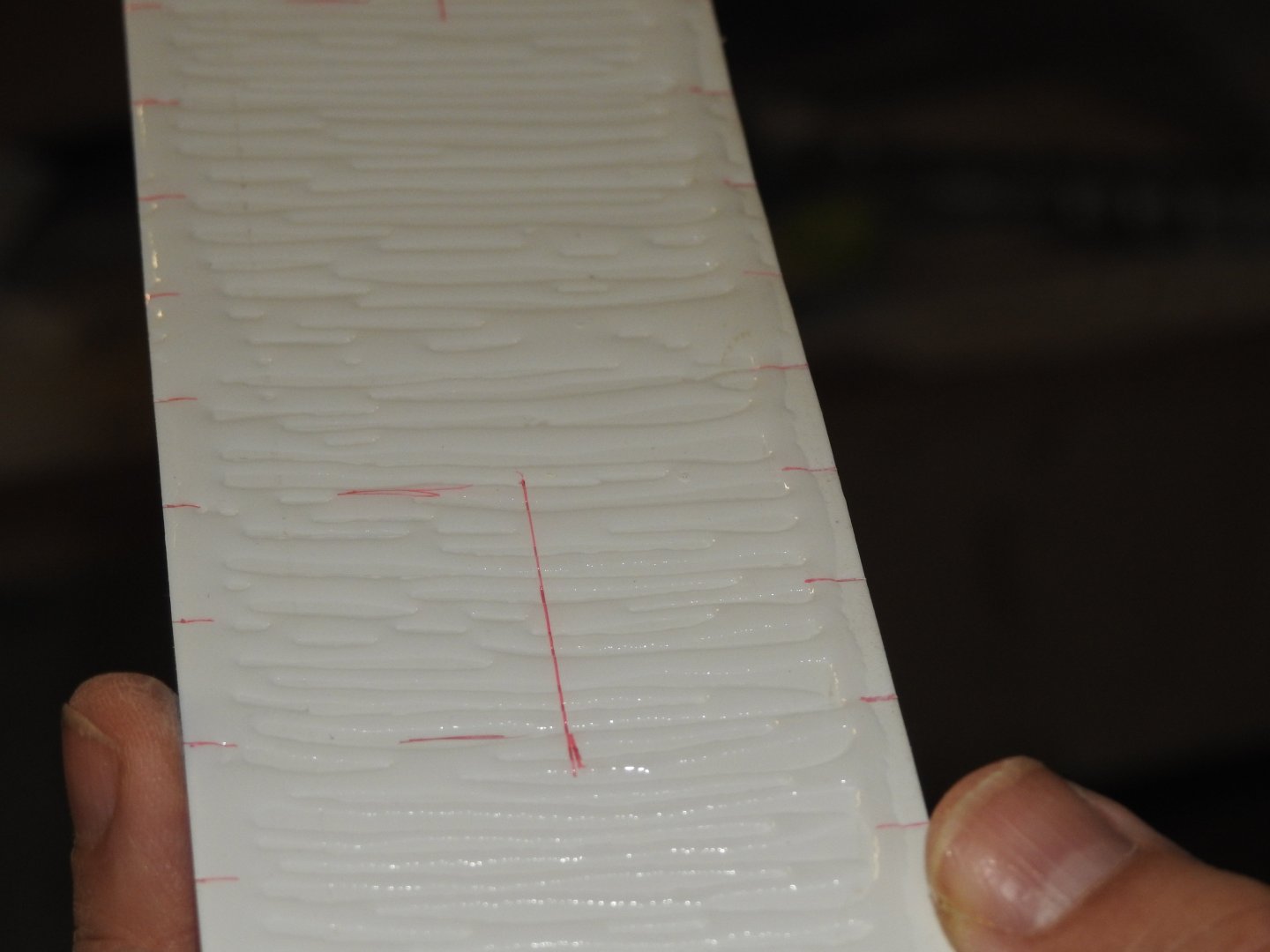
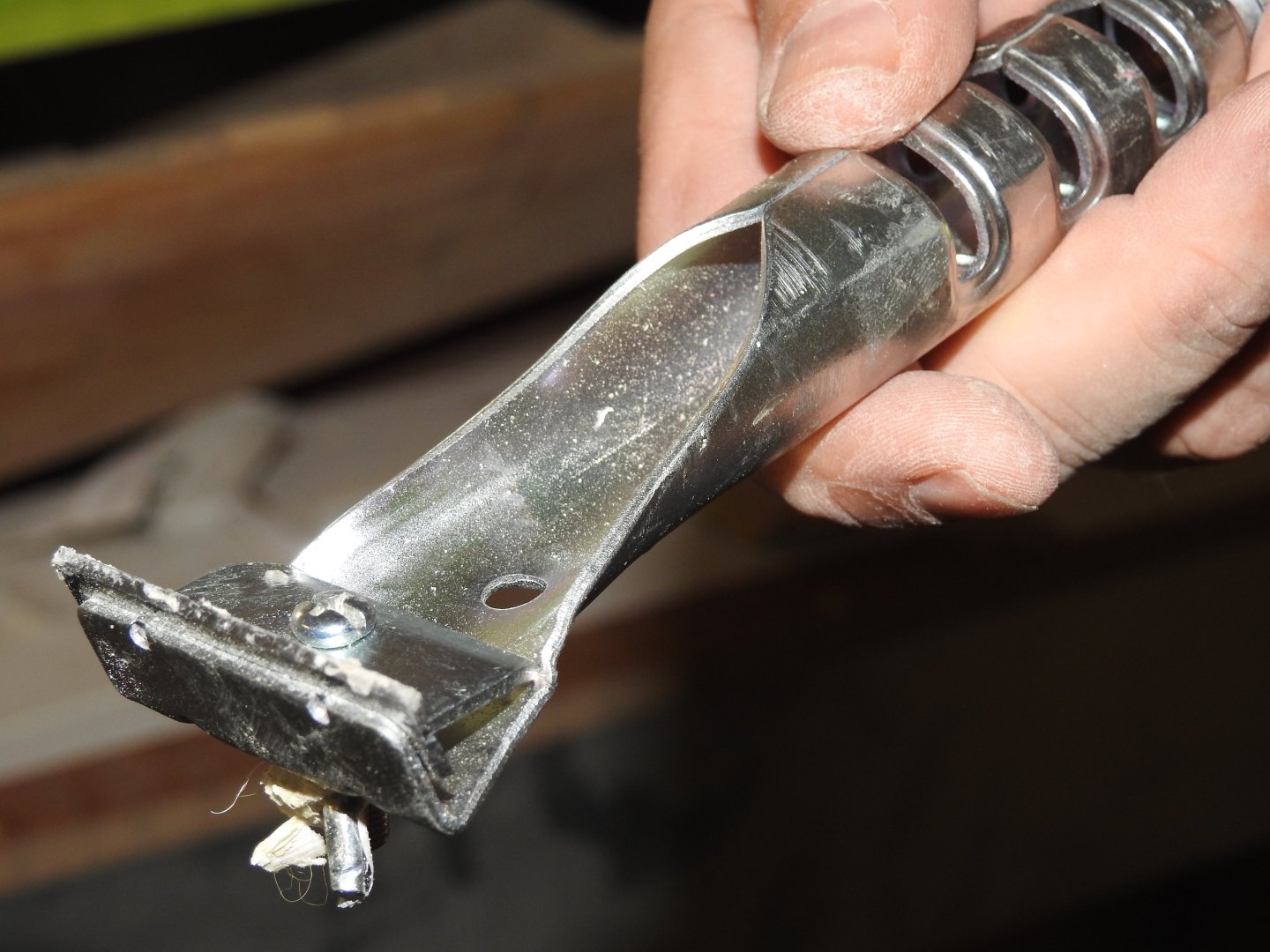
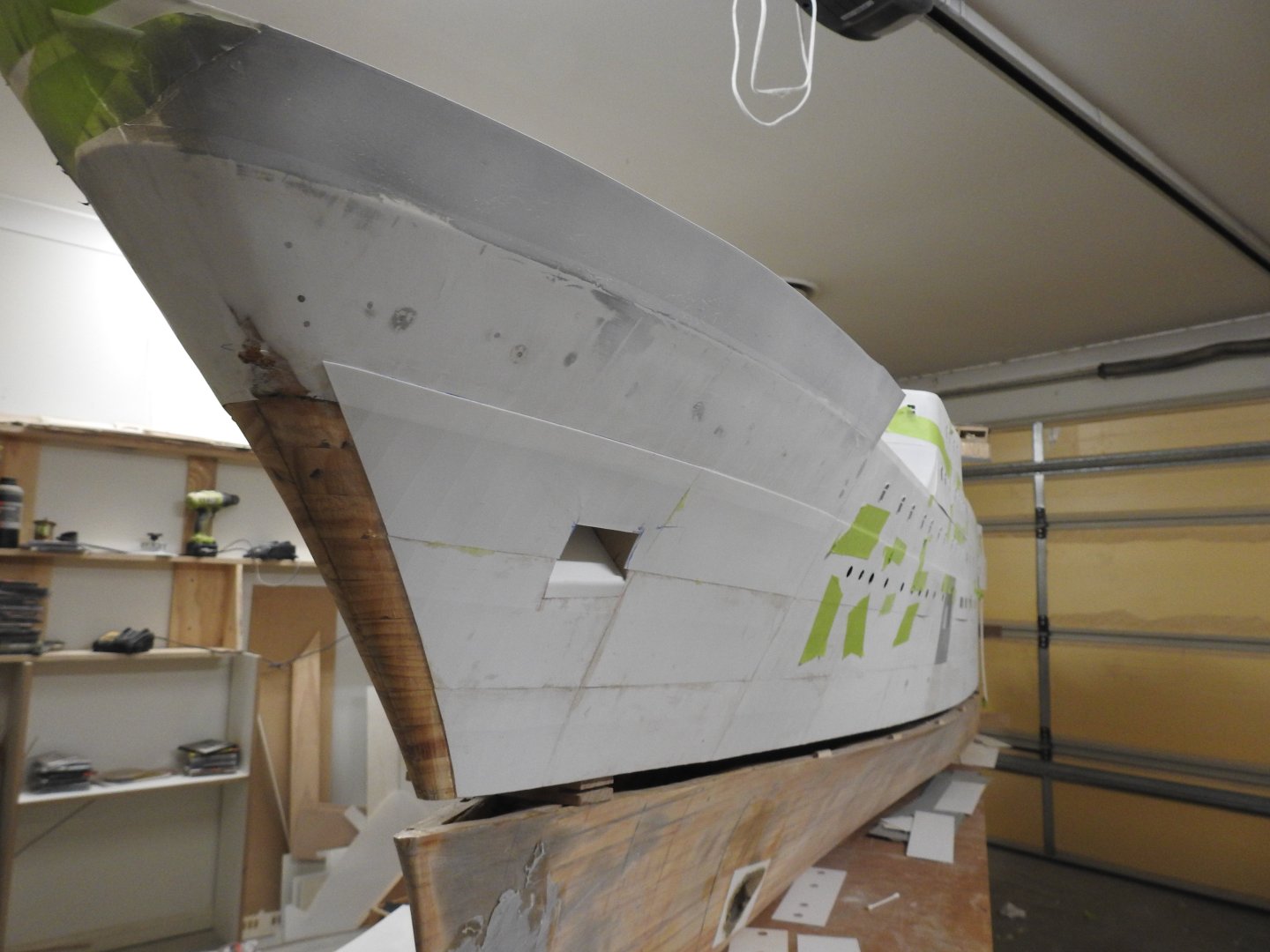
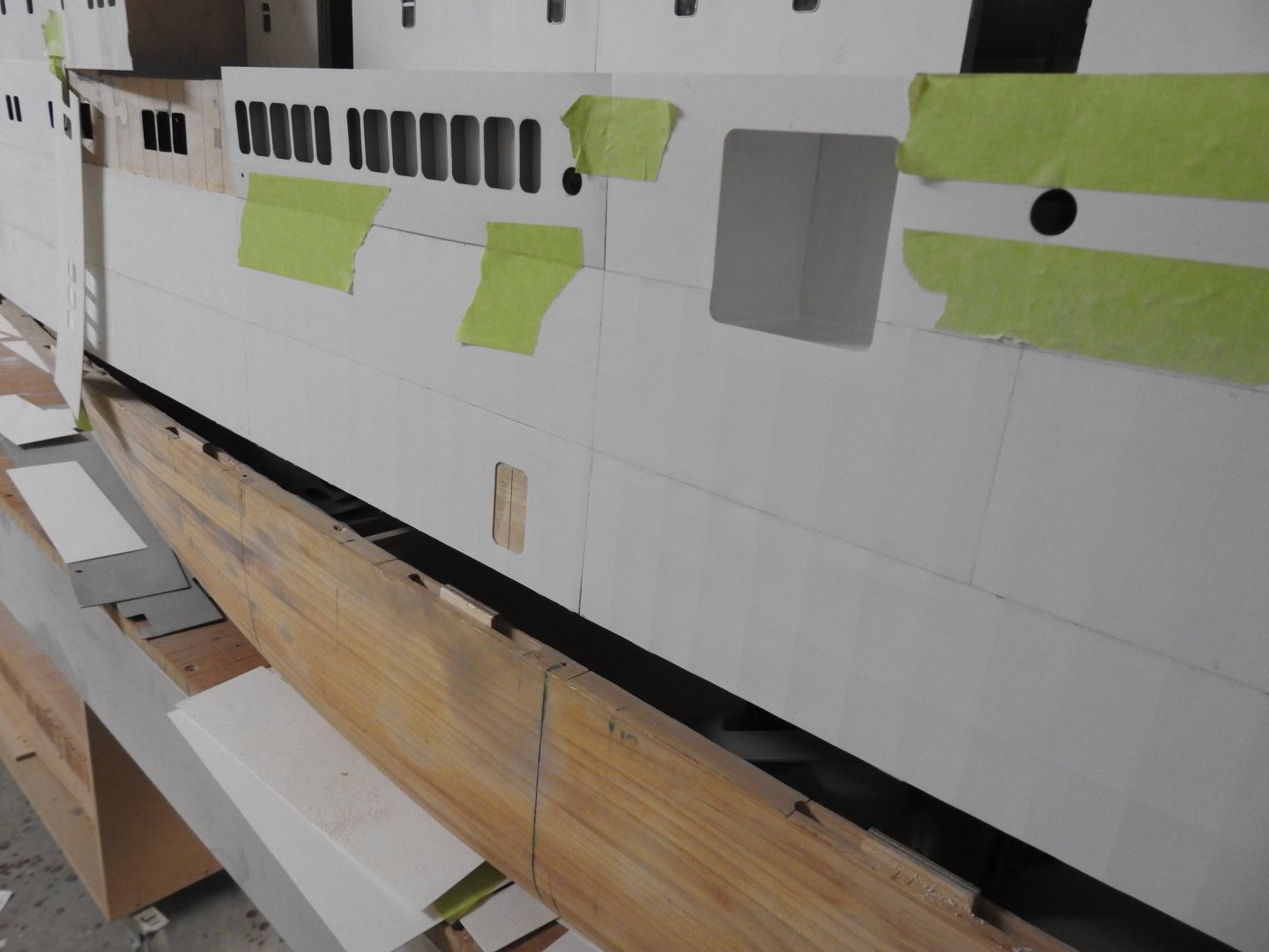
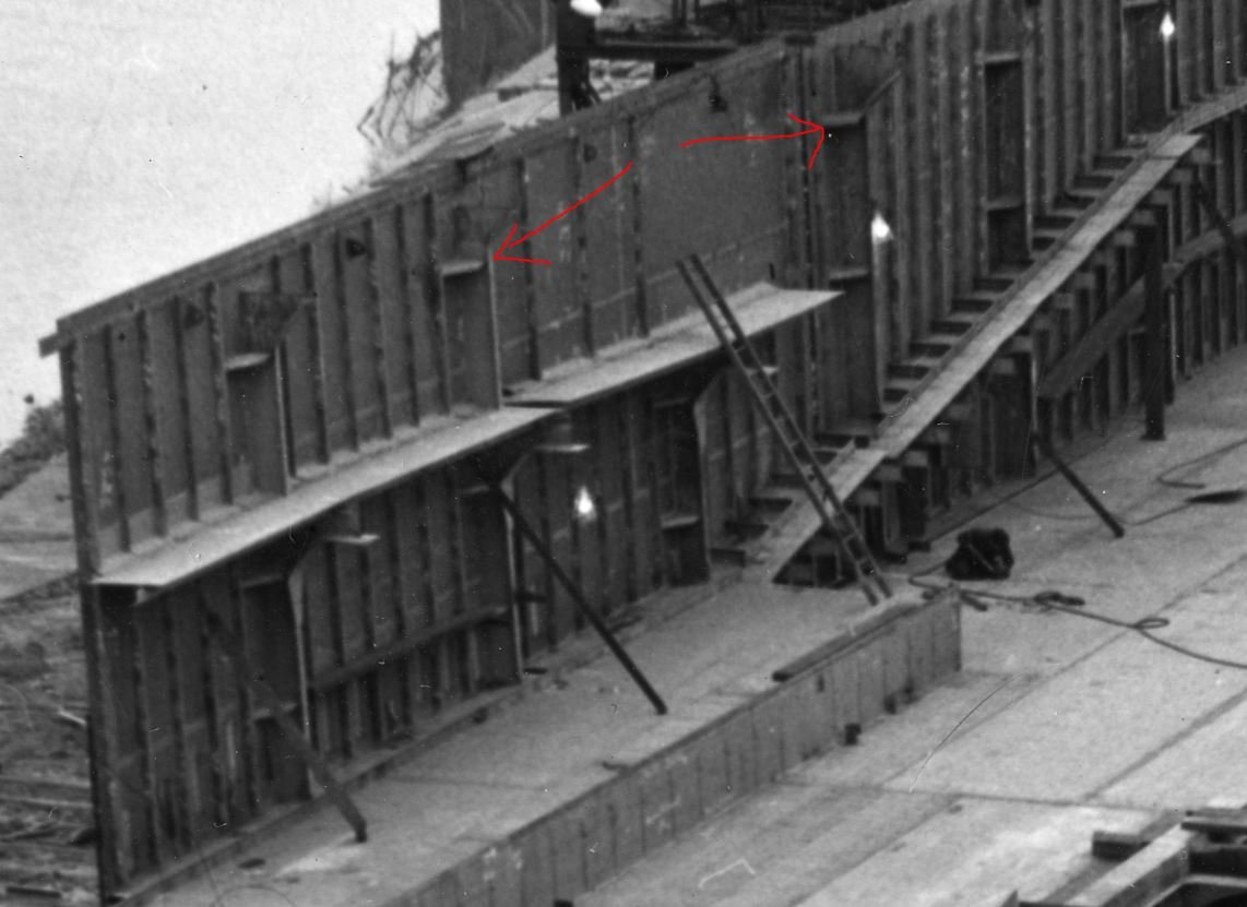
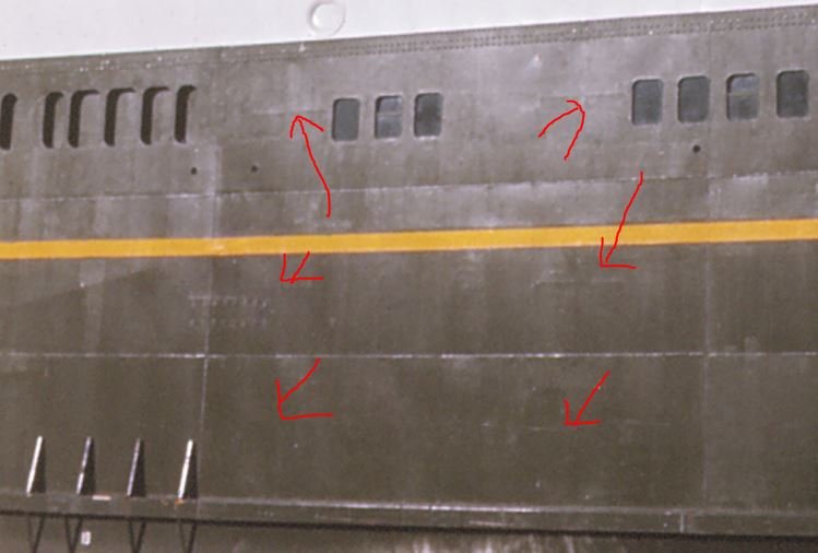
If you have clicked on this topic you are either curious or needing to know how to accomplish this job. Over the years I have seen many very talented model builders struggle with styrene plating, the concept of it seems quite straight forward and given that styrene is a heat formable medium we should be able to form it over a hull right? well anyone who has treid it knows it seldom goes to plan and often results in burn outs, blistering, melts and then requires filling. There are a few things you need to consider before starting to plate a hull in styrene. 1 what is the hull made from? 2 Is the hull going to be in the water? 3 How hot is your workshop? I found doing this in cold weather was a little harder. If I miss something please ask me to address it in the interest of being complete Ok I am going to describe the process as I approached it on my TEV Wahine model at 1/35 scale this is a hull 4.3m in length with a 600mm beam, so I needed a LOT of styrene. I bought my styrene from a plastic supplier in Brisbane where I live, the sheets are 1200mm x 1200mm and come in .5mm or 1mm. we pay about $6.00 a sheet. Starting with the hull, if you have a bread and butter or a planked hull make sure your surface is sound, no flexing planks and no flimsy thin panels, maybe glass the inside with chopped strand or mat to stiffen it up, the next step is to seal it really well, I reccomend EPICURE which is a thin epoxy that permeates the wood for 5-6mm deep, alternatively use thinned epoxy and when dry sand to a smooth surface making sure no bare wood is left, it won't affect the plate bond but if water does get under the plate we dont want bare wood. Once this was done I set the hull up on a board that has all the frames marked across it as well as the centerline, this was a lot of lines to set up and keep in mind most ships have smaller frame spacing in the fore and aft ends, mine was 27'' mid and 24'' fore and aft. Once you have your hull sitting on these lines and on the centreline and have it braced level you wil need to transfer the frame lines on to the hull, the sides can be done with a square and marking off along the keel should not be to hard while is upside down, but the areas along the bilge can be a problem I reccomend a series of ply or cardboard squares that you can sit on the board and bend into the hull just ensure the square templates sit parrallel to the ships centerline, once these points are marked turn the hull over and join the dots with a flexible batten, it's a big job, for me it took 2 days due to the share size. Below can be seen the frame lines marked on the bow sides, note aso the blue protective film on some plates Here we see the affect on the edge of the plate, the reality of the shape is very very close to the real thing. Now it gets interesting, I will approach this from the perspective of a modeler who has a shell expansion. I reccomend printing it to the exact size of the model, however a word of warning, hand drawn expansions are seldom accurate in the girth along it's length consistently, so I reccomend checking it midship and fore and aft and maybe printing them in sections correcting the vertical scale as needed. Start by marking off the tanktop plates paying attention to the butt locatons and the plate widths, the tank top line should where parallel to the base line and be traced on hull the same way as a waterline is, as should any line that meets this rule. The other seams can then be marked off along the girths at the plates ends and midway long its length, join all the curves up with a batten. I would reccomend doing all this is dark blue or black ink, use pencil initially, but ink it in once you are happy. Then we do the often missed part,the stringers, longitudinals and tripping brackets, if you have structural plans you should use them to mark all the girders in the double bottom or others in the ship, tripping barckets ar often found on ships web frames. A good shell expansion has all this info, see the one provided below.. Once all this is done check your work and check it again making corrections, check the model against photos for obvious things that don't match and decide how to correct it. In my case I had AS FITTED plans and nothing was different. This is where we can start plating, we do not need to start in one place like planking or coppering but I reccomend starting with the keel plates. cut strips for the keel plate and lay them on the inverted hull and mark the butts and also the frame position, cut the parts to length and square off the frame lines with a pen. Below shows a set of plates printed out at 1:1 with frames and structurals marked on it, the short lines are tripping brackets on the web frames on every 7th frame, seen in the 2 images below the next image, You can see the effect from both sides. The lines being transferred to the styrene plate Creating the deck line crease. Creating the frame lines. it takes about 3-5 passes with quite firm pressure, if you press to hard you will split the styrene and have to throw the plate. Here we see a tripping bracket that only spans 2 frames being rolled by keeping the wheel between those marks. Prepare yourself a rubber mat, not a soft one and get yourself a nice robust pizza cutter, this is important, don't get one that has too much wobble. Optionally use a self adhesive film and cover the outside of the plate to protect it, I used floor covering film for newly laid wood floors, Its ona roll 30cm wide, I reccomend doing this to the sheets of styrene before cutting them. Once this is done lie them face down on the rubber and with a thick straight edge run the pizza wheel over the frame lines, you will need to try this to guage how many passes and how much pressure is needed but try it out, in most cases welded plates have this distortion in the middle of the plate but it is not there at the very edge adajacent to the actual seam, so if you are careful you can acheive this by not running all the way to the edge but stop 5-3mm from it applying more pressure in the middle of the plate, repeat this for any structural members on the plate that you have marked off the hull, you should be able to see through the styrene if you inked in the lines with dark colour, if not just move the plate back a bit and mark them off around the edges. Now comes the weld seam part, there are 3 ways to do this. 1 Masking of the seams leaving a .5mm gap between the tape and useing a high build primer 2 Recessing .5mm styrene rod into a prepped gap 3 Gluing styrene rod directly to the shell over the seams The glue used is Starbond Thick Applying the glue to show how much is used. we are laying downa lot of Cyano make sure you have ventilation! The plate prep done in advance, we then apply the plate. Cleaning up the squeeze out After a minute or two scrape the edges clean for the next plate. Once cleaned and sanded with 400 grit paper the area looks clean and ready for seams to be applied. You could prime the plates in section at this point to refine the surface and then sand away on the seams before gluing the rod on, its probably what I will do so I can sand the hull without dulling the raised seams. Even though we are using the same thickness styrene we get some subtle variations in the plate heights to, very small variations mind you but it sells the effect. In regards to the seams I will address type 2 as it's the most accurate. Once you have prepared a plate and done all the wheelwork run around it's seam perimeter with blade to create a very small bevel of about 30 degrees, not 45 its too much. if you do option 3 this is not needed. This is the time to glue the plates, I strongly reccomend Starbond for this, It's the only Cyano that gave me the absolute strength and working time of 3-4 mins, also it's thick and comes in big bottles. Starbond costs about $85.00Au for a 16oz bottle, 3 bottles did my model which is a little bit bigger than most. Cover the back of the plate with glue and place it on the model in place move around constantly pushing it down to the hull gradually you can just rub it and it will stay, before the glue sets keep scraping the glue away from the edge and wipe any mess of the face, its nearly impossible to do this cleanly hence the film, and again wear gloves and a mask, the fumes from cyano in this quantity are something else they burn your eyes. Once the keel plates are done move onto other flat plates working away from midship and out towards the bilge. I will now address forming the 3d shaped plates., this is what worked for me and my plates were bigger than an A4 sheet. Cut a peice of styrene quite a bit bigger than you need, styrene is cheap so it's not a problem tape it along a seam on a flat part of the hull and then drill a couple of holes in the overhanging bottom edge, I reccomend tying a metal pipe onto the outer edge and let it go gently so its hanging down the side of the upside down hull, if you have not guessed now we will heat it very carefuly and slowly with heatgun, move the gun rapidly in lines, like you are spray painting but speed up the reason this works is because as it forms it stretches slightly and pulls trouble areas out of the surface, I am not claiming this worked every time, sometimes it took me 2-3 goes on a plate untill I got a good usable one . Once this has cooled trim it into plates and do your wheel work and bond to the hull. Below shows the 6 white plates which have been formed from just one sheet and cut into plates. yes all those plates got formed in one go from a big piece of styrene Note the keel plates over by the right hand end of the ruler, then the flat bottom plates, here yet to be cut and finally the bilge plates, I reccomend forming the plates well before you get to that area so you dont damage bonded plates with heat. but you can see here all 6 formed plates are done flawlessly, no blisters or warping and the seams are tight. The remaining step is to glue in the .5 rod for the seams, if you do not bevel the plates scrape a flat on one side of the rod and tape it in postion over the seams and use liquad cement to glue it on, if you roll it down using uneven pressure you will get the subtle variations in bead width as well. I hope this helps, I should also mention I have done half my massive hull with this in Australian in temps of 10 degrees celcius up to 40 and have had not had movement or gaps open and absolutley no delamination over an 18 month period. I had to remove a plate and I hope I never have to again, it literally had to be chiseled off, it did not come away on its own at all. A section showing the result with seams in place. Anyway that's my way of doing this, I suspect this is not apealling to all modellers but for large scale builders who want to show the hullas it was and not looking like a super yacht this works well. Below are 2 more shots of the effect and the deck lines as well showing through compared to the real ship so you hopefully see how accuarte it is, lighting has been increased for effect. A shot of the bow plating. The top overlapping plate is a riveted seam. Yes I cracked the Bulwark around the bow but will reinforce it with thinner styrene inside between stays.


-
How are you going to do the gingerbread work Keith? I assume modelling clay? Speaking of that I wish Doris would repost her videos on that subject.
-
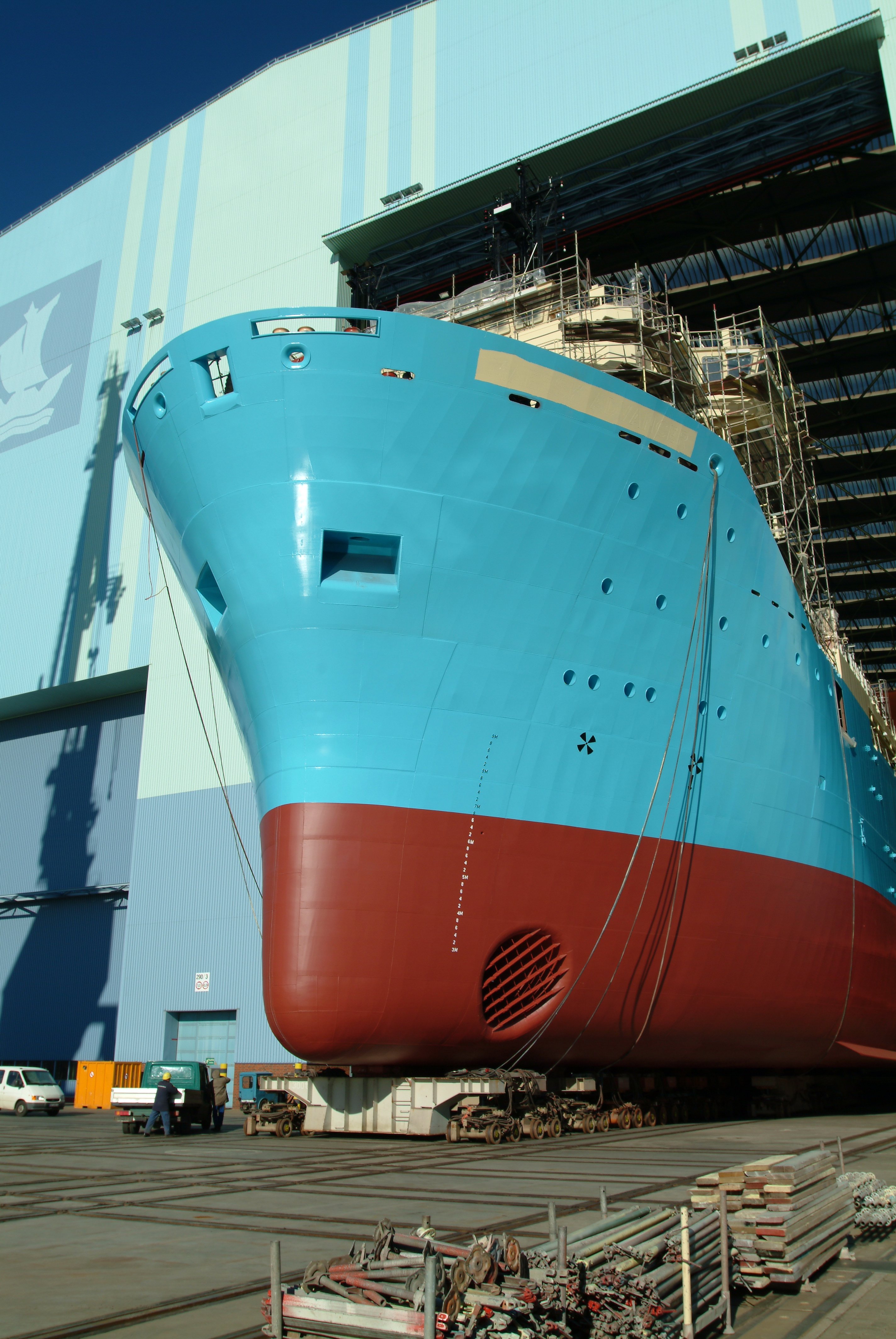
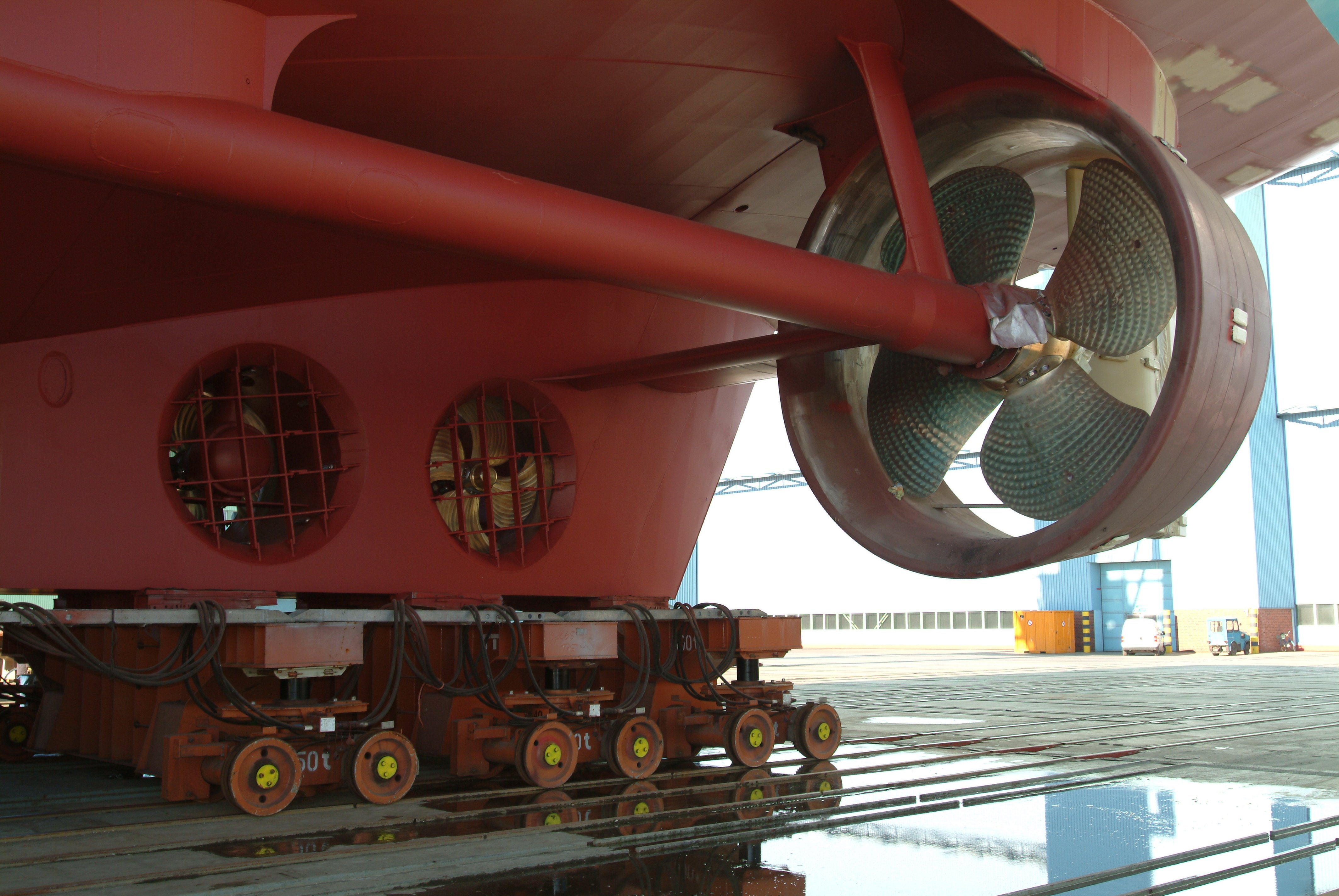
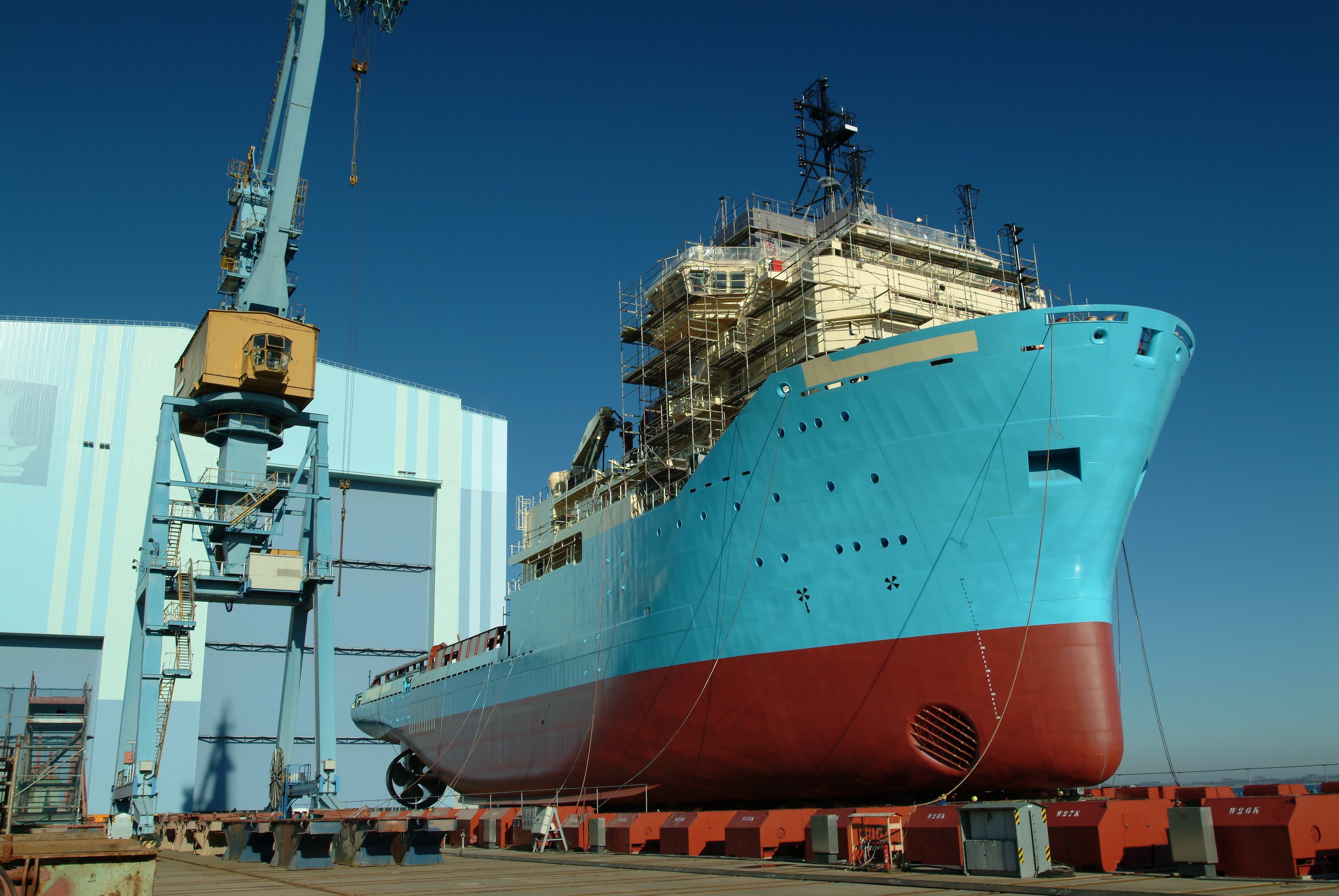
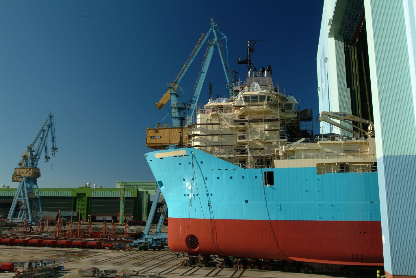
Some shots of plating and comparison images. The ship in these images is Maersk Advancer


- 454 replies
-
- 5
-
-
-
- Union Steamship Company
- Stepcraft 840
- (and 3 more)
-
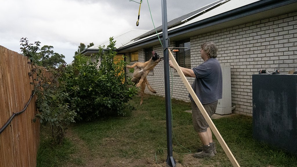
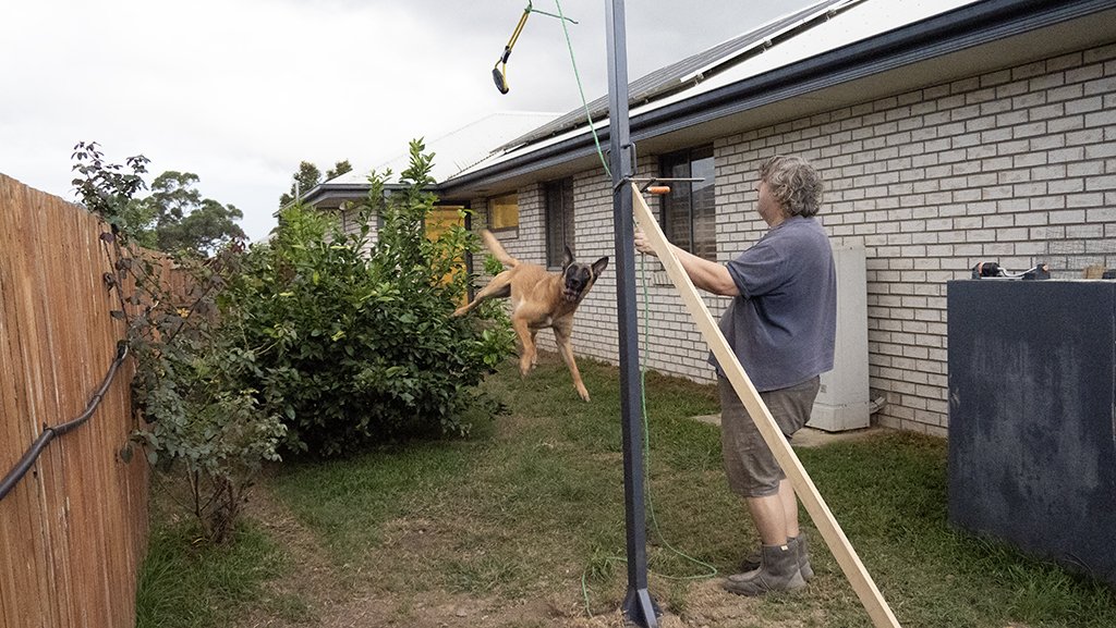
Yep and they do that stuff for fun,Here is our pole for that sort of work. And just for a laugh here is the expression when she realises she has to come down again. Priceless
- 454 replies
-
- 4
-
-

-
- Union Steamship Company
- Stepcraft 840
- (and 3 more)
-
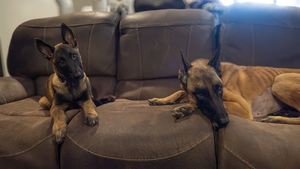
Yes she has, 4 weeks ago she started to lose weight and long story short she had a whole passionfruit that had been in her tummy for 2 years removed from her intestine, it had just tried to move from the tummy into the intestine and got stuck, so yes she has had major surgery but is all good now and just needs to put on weight which will take 2-3 months. The dogs are both Belgian Malinois and being trained for sport agility and scent work. The dog on floor training seems to be going badly!...not sure what you mean by this? If you mean why are they on the couch ,this is their couch in the office, Jasmin on the right is highly trained, the puppy "Cato" to a lesser extent being only 4 months, but they have boundries and do not get on our furniture or the carpet but they have a couch they can curl up on. We have a whole youtube channel on stuff these dogs can do and they are in the top 5% of trained dogs...hence why I dont do as much modelling as I did 2 years ago.
- 454 replies
-
- 1
-
-
- Union Steamship Company
- Stepcraft 840
- (and 3 more)
-
Yeah its been a busy year with two other commission models on the go and flat out at work as well as a new puppy to train.
- 454 replies
-
- 5
-
-
- Union Steamship Company
- Stepcraft 840
- (and 3 more)
-
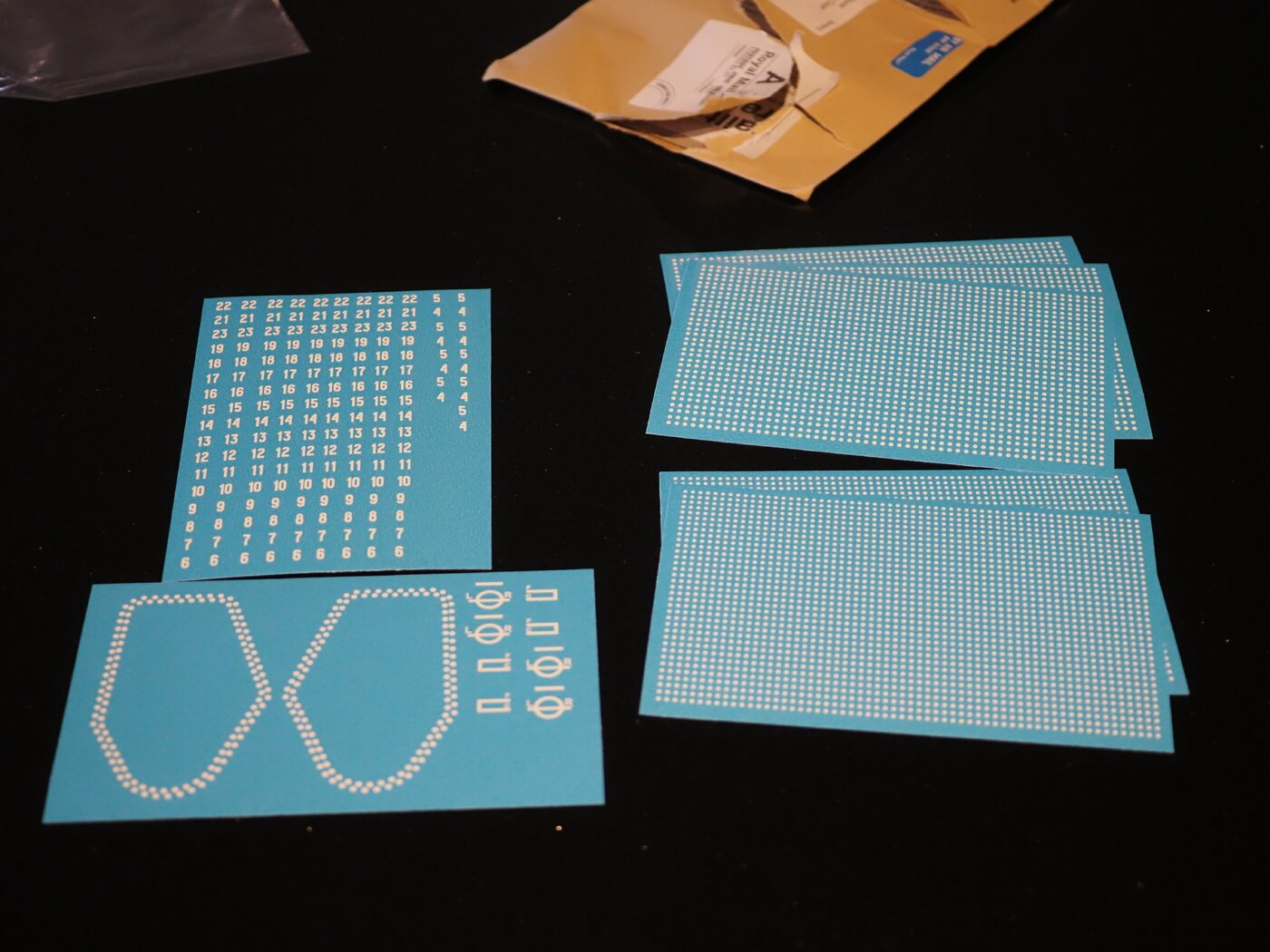
While doing some work on 2 other models which are now done I gave this a year to really check the stability of the styrene across a full year of seasons and things are absolutely fine. no sign of delamination or loss of adhesion, so I can gladly say plating resumes this weekend, It's been a while but it was time well spent to make sure it's not all wasted work. Over this time I also got the 3d resin decals made for the draught marks, rivets and plimsol lines
- 454 replies
-
- 7
-
-
- Union Steamship Company
- Stepcraft 840
- (and 3 more)
-
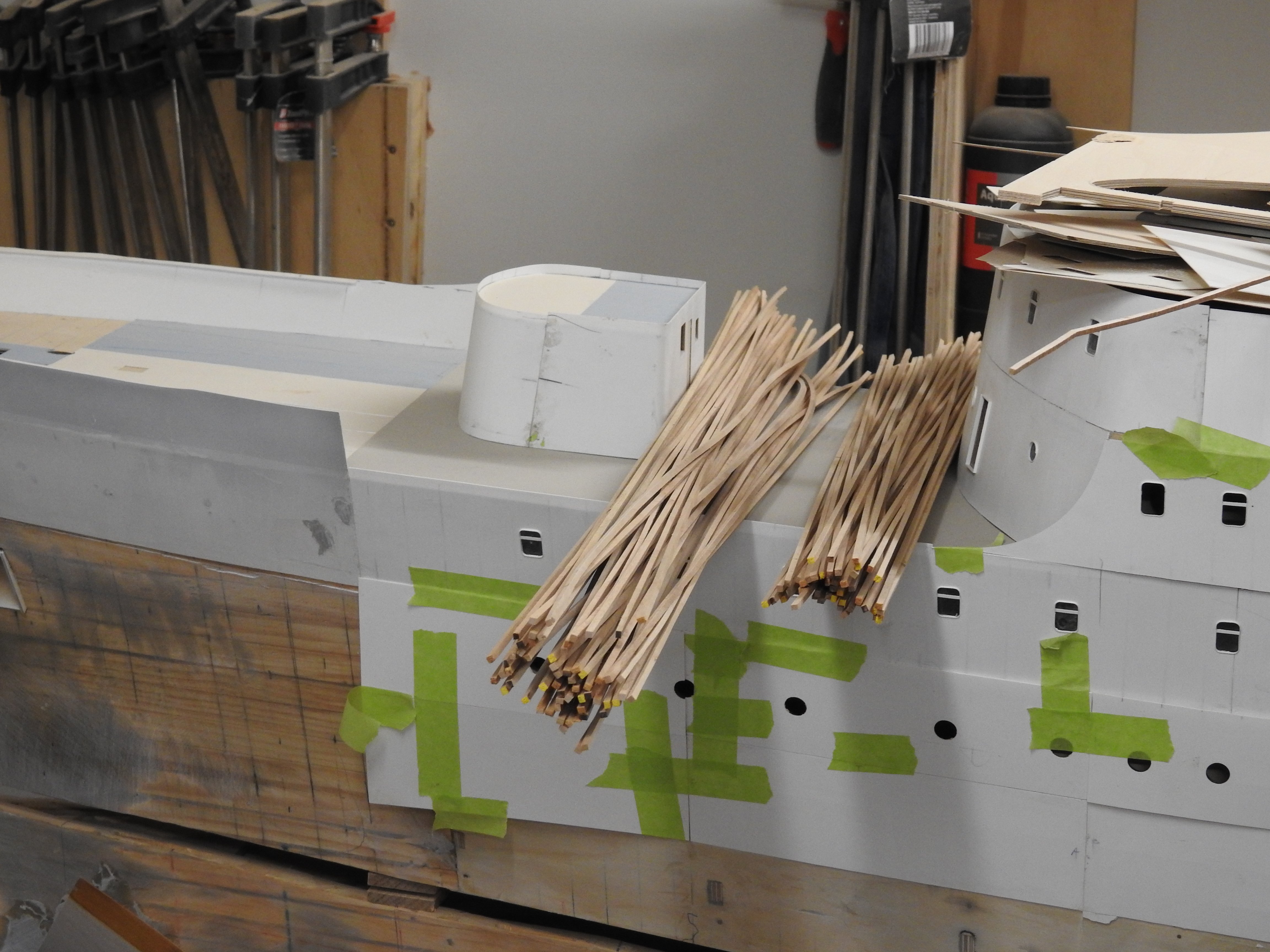
Laminate bulwarks Deck planking ripped ready for cutting to length.


-
The kit as far as it was required was complete, sorry I have not updated this build as much as others. I have not had time to plank the hull or deck yet as other paid work has come up. I will post some images soon
-
This model barely even looks like CS, wrong lines, out of scale features and planking just as start, I am not going to say anything else as most people are aware of this already. My kit is for people who want an accurate model. and are able to and prepared to do a lot of scratch building as well.