HOLIDAY DONATION DRIVE - SUPPORT MSW - DO YOUR PART TO KEEP THIS GREAT FORUM GOING! (89 donations so far out of 49,000 members - C'mon guys!)
×


Richard Dunn
-
Posts
529 -
Joined
-
Last visited
Content Type
Profiles
Forums
Gallery
Events
Everything posted by Richard Dunn
-
 Yep this is not affected by the heat, neither is the glue, it's been 7 months now since I put this on and we have had temperatures to 38 degrees Celsius outside (100 degrees Fahrenheit), hotter in garage without AC on and it's still not coming off even if I tried, this is I believe due to the Starbond Cyano glue. In fact getting a plate off even if you want to is a massive job, you have to chisel it off and scrape, you literally cant pull it off.. its amazing' Of course this has not been in direct sun, not game to do that without paint as UV WILL make the styrene brittle but as long as hot days are avoided and its kept in the case when not in the water I don't foresee any problems. I know lots of people have warned me about this which is why I have taken the time to test it, all I can say is try it with starbond Cyano its a different result. vhttps://starbond.com/ I should also say that the test samples done with Techniglue Epoxy have creeped slightly ( almost imperceptible) and as expected contact glued fell off completely, back when I was in the trade and when we needed to remove laminate Formica from something we used a heat gun and scraper to remove it as it's always contact glued so it makes sense that in hot weather its not going to hold, I had also used contact for deck plates on a previous model and that all lifted within 12 months I want to video me getting a plate off at some point to show everyone how good the bond is, it's actually worth taking the time and showing you. and no sanding or scuffing of styrene was done, just used the dull side. I have also tried ZAP brand and Bob Smith Industries glue, both worked well but could be pulled off in a couple of pieces, not in the same league I am afraid, though certainly good enough for a normal sized model but if doing a large surface....., and you have to buy small bottles you need to take out a second mortgage, that's another big advantage to Starbond, it comes in huge 16 fl ounce bottles and is not as expensive proportionally.
- 454 replies
-
- 4
-

-
- Union Steamship Company
- Stepcraft 840
- (and 3 more)
-
Yeah the second option fell through as well. I can say now it was to the "Interislander" and I was proposing it goes in one of the new terminal buildings since Tamahine was the first purpose built one. But alas they wanted it for free and also decided it was not relevant as it was not owned by the same line. Back then it was the Union Steam Ship Company and they went under in the 80's, if the first purpose built vessel for the run is not of historical relevance I don't know what is but ok... pretty narrow minded IMO but oh well.
-
I might have found a new client for this, a more fitting one funnily enough, in talks now.
-
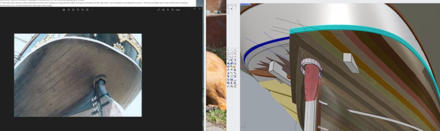
I did more work than I got paid for in the hopes that the progress shots of a complete shell would help to keep the project going once I heard the company were cutting costs, probably naïve of me to think it would change anything but the next job on this is laying the decks and will do that at same time as the Cutty Sark kit I am designing. Never mind, I will come back to it.
-
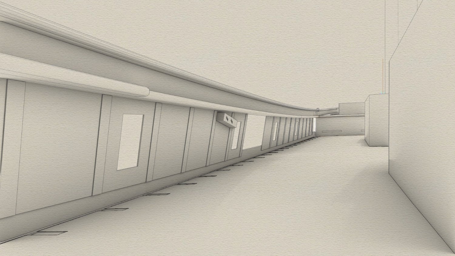
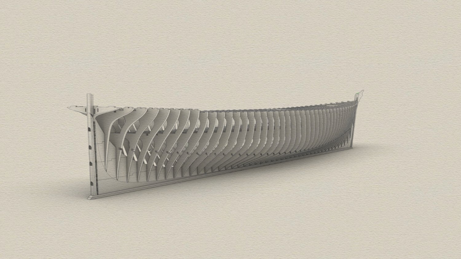
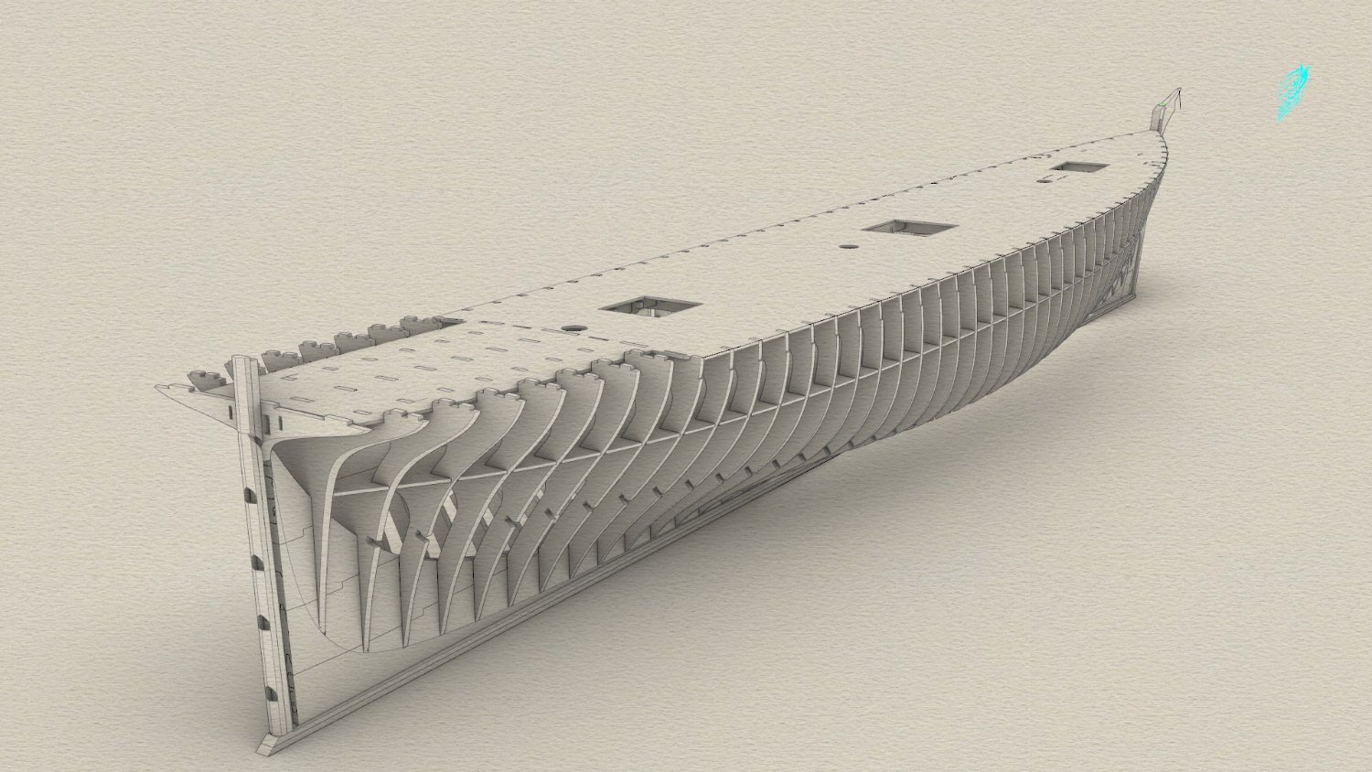
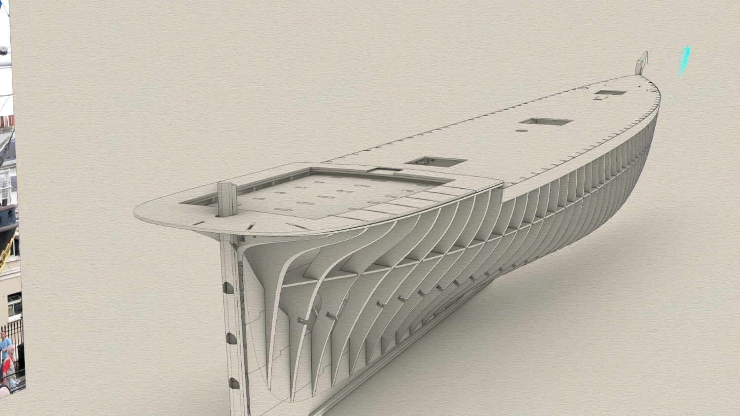
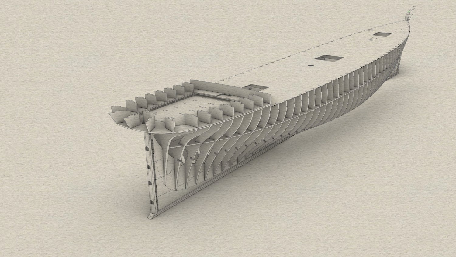
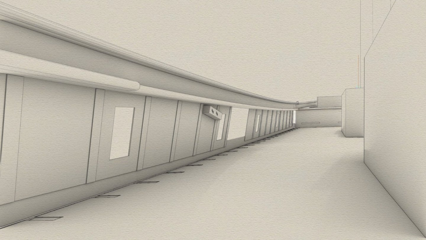
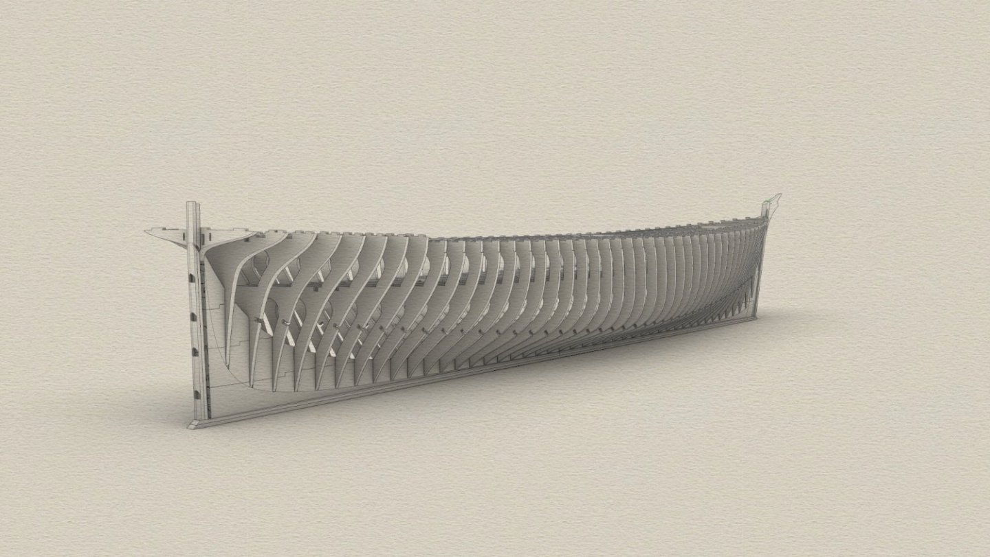
Construction of the bulwark, still not sure if it will be brass or .5mm ply. Note the brass butt straps on the bulwark where the stanchions go they are spaced every 40mm so ply would probably be strong enough given its 1mm total in those places, butt straps need to be brass so stanchions can be soldered to them The variation in the protruding height of the sheerplate can be seen here and below which had to be measured at every stanchion as it's impossible to get right without it, luckily we have a nice 4mm overlap for a good solid joint (seen where a plate is turned off). The angle iron margin angles and the one connecting the main rail to the plates underneath can be made from styrene profile. Anyway time to start cutting the Axial timbers and frames this weekend. Then it will really be apparent how small this actually is without spars.
-
I just realised I have not updated this. This build has gone from commission to personal now and taken the back burner as the client has run into financial trouble and of course this is not a priority in the eye of the creditors, understandable I suppose but anyway I will work on it myself, alongside the CS kit I am designing as it has many of the same things.
-
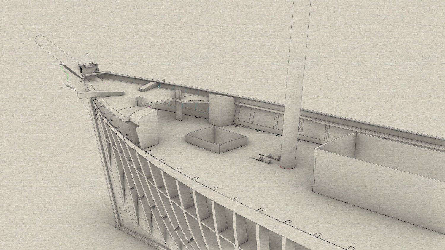
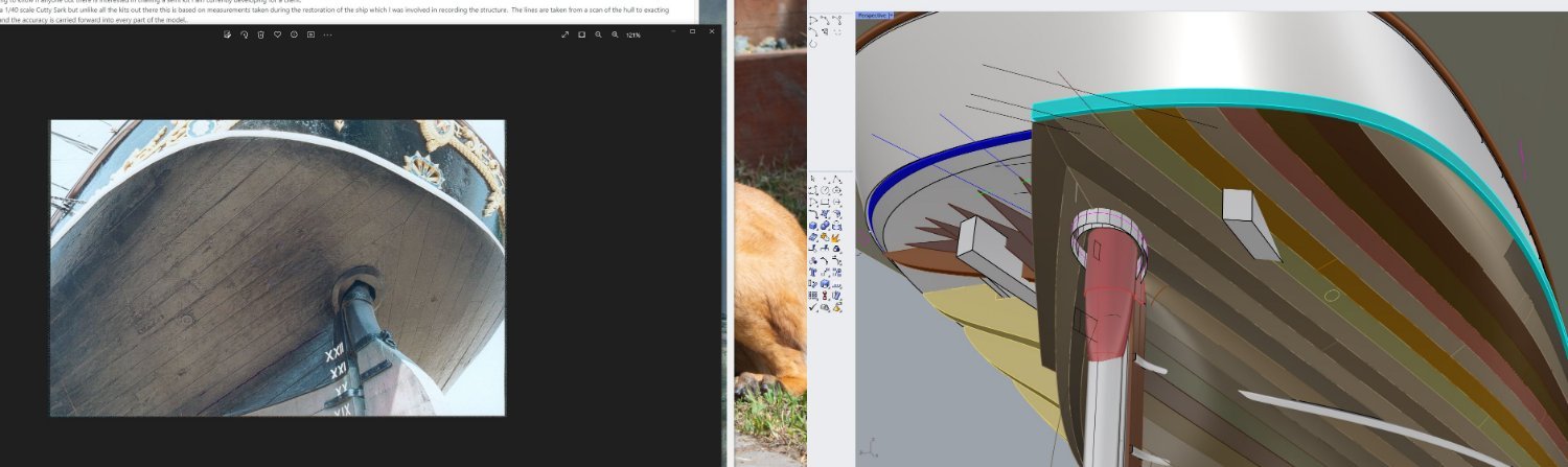
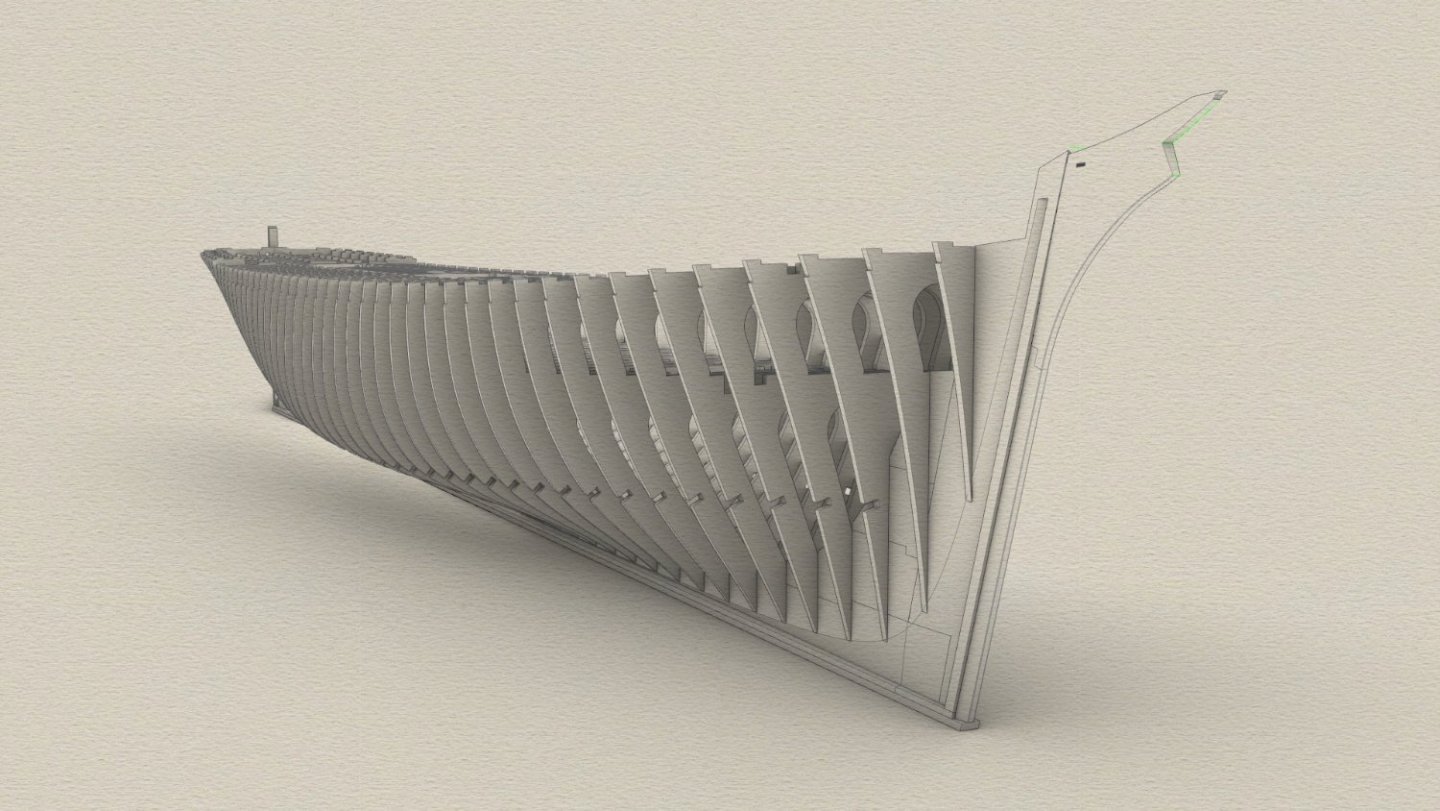
Thanks guys I should add a certain amount of customisation can be done to what's above to. The Tween deck can be left un planked if the hatch covers are closed but the decks themselves form a vital part of the structure with how they notch around the frames at both deck levels, you could just pen in the planking to but I would plank it as far as you can see in the hatch's, which is not much at all. Also the stem and cutwater shown in image 1 is currently in one piece, this will be made of all the correct parts, some quite small at this scale but I think it's important to include them as less then half are under the trail boards. Also the stem and sternpost are built form the same pieces and size as original as far as what can be seen outside rabbet so that should follow to everything including the cutwater and knightheads The saloon could also be left unfitted out but if you leave companion doors open you can still see through the skylight, and that is about 80mm long. The precision and fit of parts is not a concern, some of you may have already seen the 2 other build blogs on here, both of which are CNC cut, the 1/35 Wahine and the 1/48 Tamahine which was a commission job, sadly that has fallen through due to financial trouble with the NZ based client company but will get finished at some stage. both these below builds illustrate the way the joints work.
-
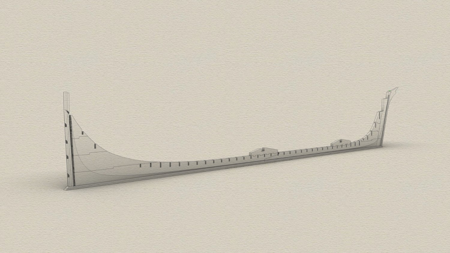
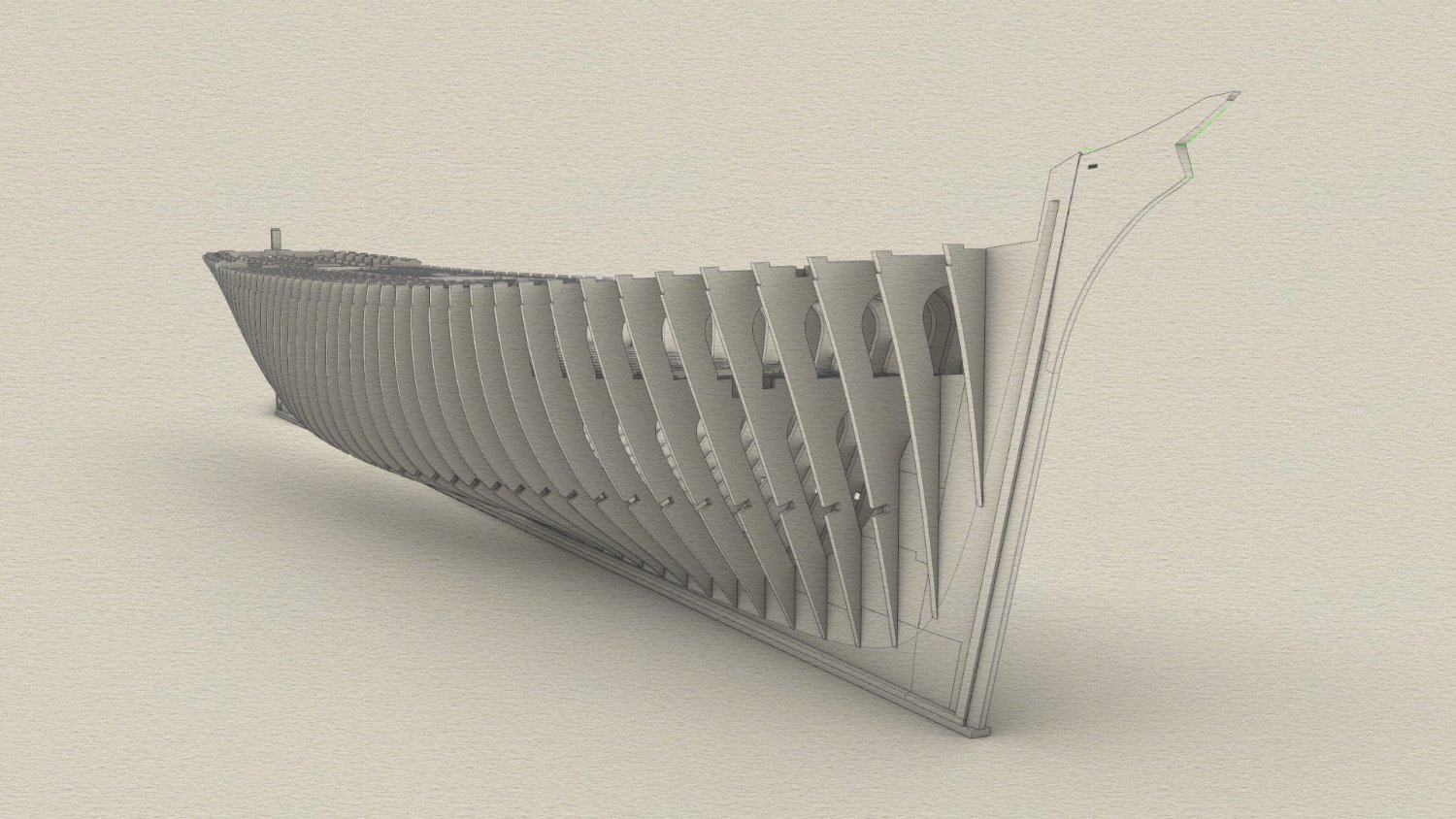
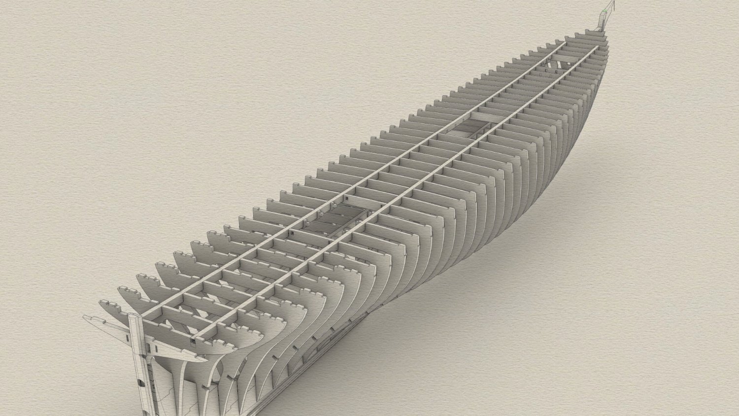
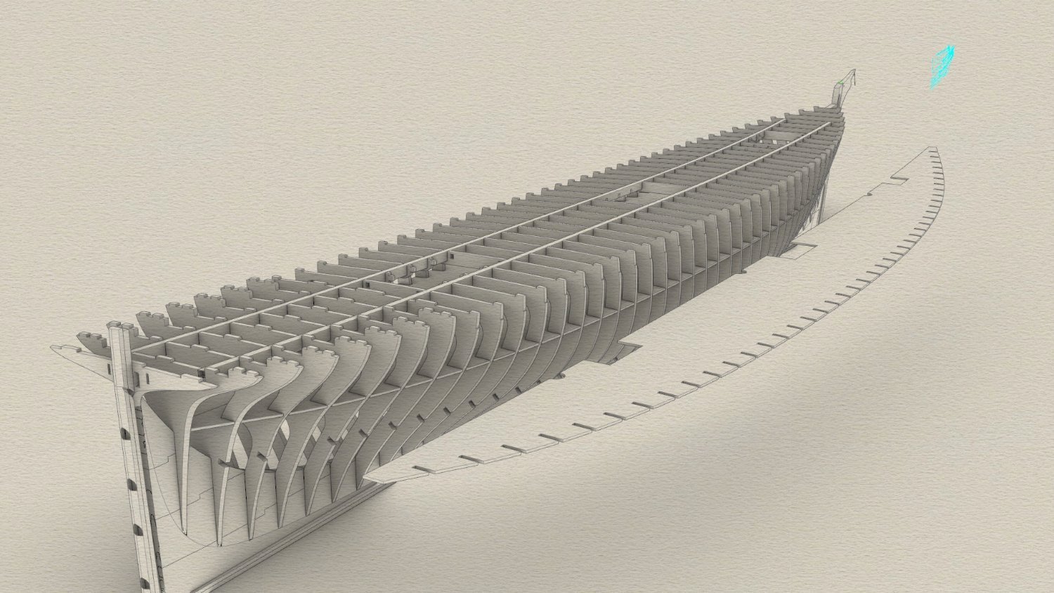
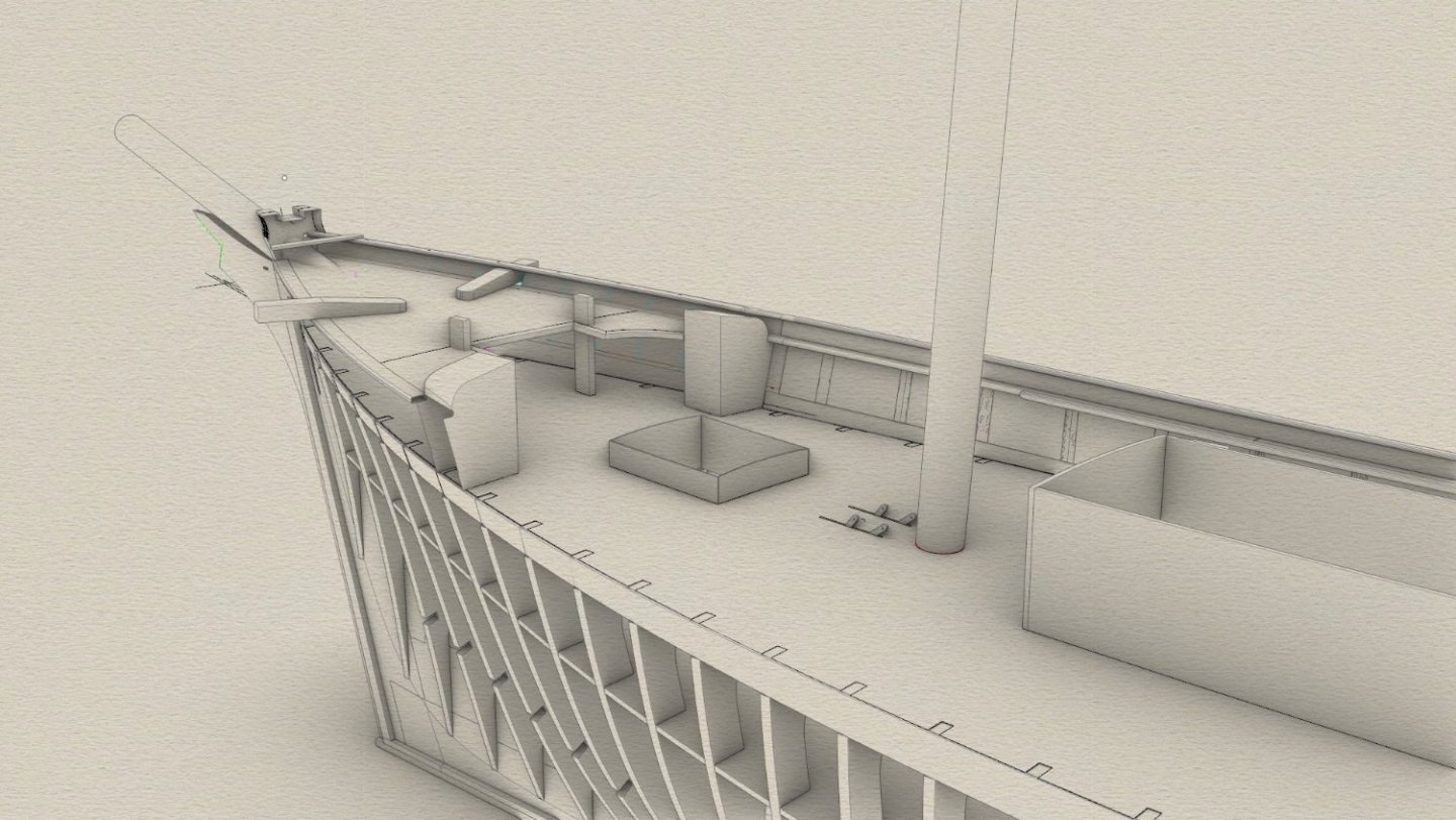
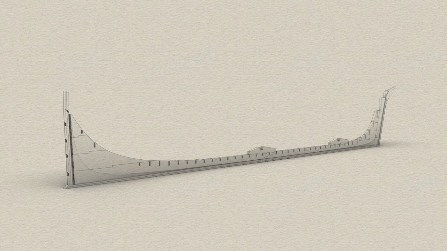
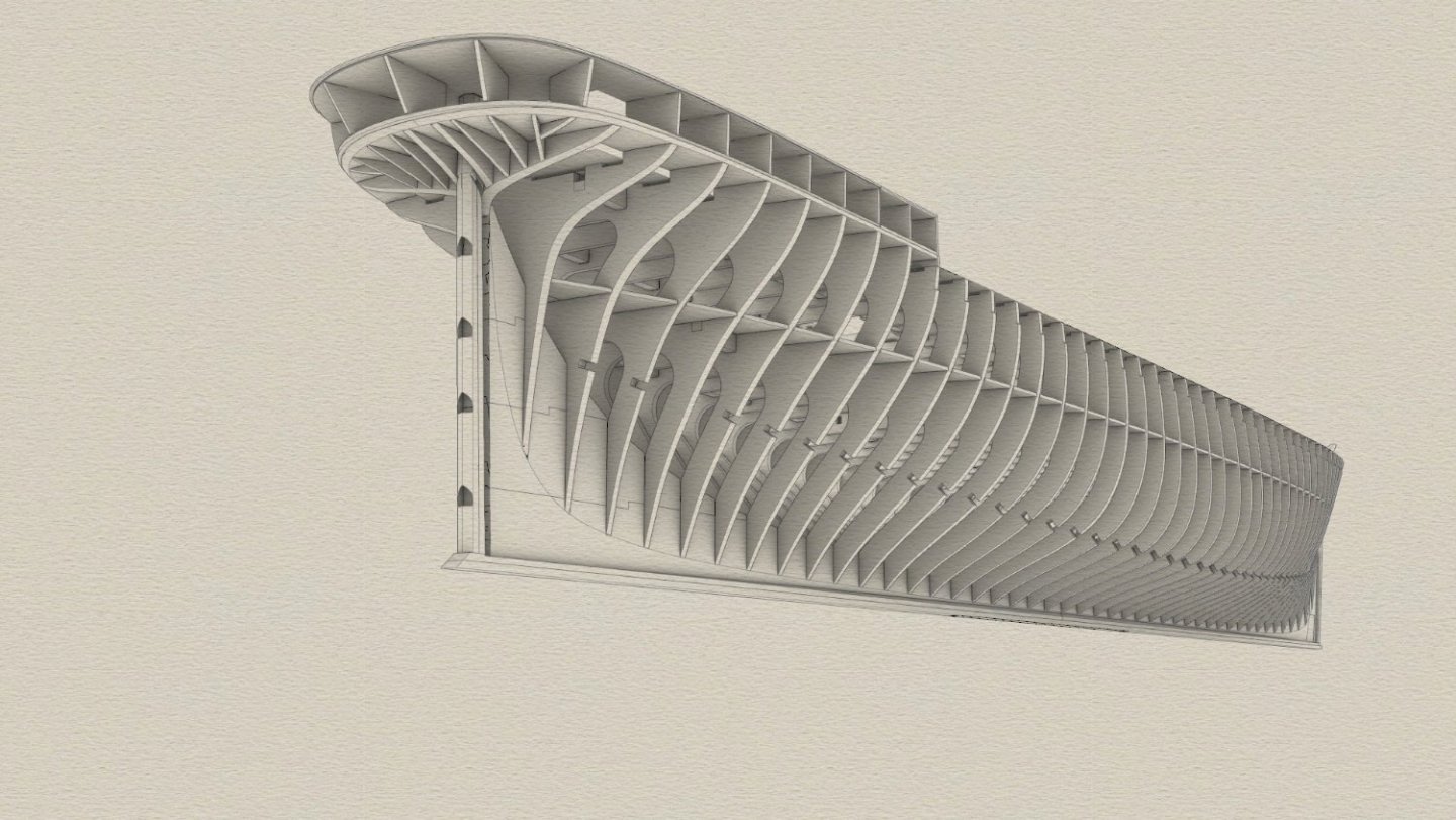
Starting to plan build sequence Axial structure with rabbet cut. Aft deadwood not complete here and missing mizzen footing Frames installed The pre planked tween deck halves need to be inside before last frames go up Deck longitudinal stringers added Tween deck fitted Main deck and Saloon floor attached Counter bed layers Poop break and Poop fillers fitted Cant frames


-
Ah I see, I took it wrongly, sorry about that Jaager, the joys of written text without context. The problem we have in Australia is that wood in general has become very hard to source, exotic timber including our own "furniture timbers" are also very hard to get, I build guitars as I said and even some of the renowned tone woods we grow over here like Tasmanian Blackwood,, you just cant get it, same with maple and many others you mentioned. I had Anigre laying around and realised it was a perfect match and I could buy it in large quantities at the time last year, I purchased the last of it in this state anyway and it should last a while. I cut the blanks on the weekend ready for final sizing and I am still glad I used it despite the dulling effect
-
The post that was directed at me implied to me that I do not know my timbers and that I should ”validate” the wood I thought was Anigre. I have been using timber all my life professionally in furniture and guitars, more species than most even get the privilege to use, heck I even have stocks of Brazilian Rosewood slabs, now banned under the cites treaty, but I am not going to go into a rant about my experience as it’s not way to handle this, and why should anyone believe me anyway. To be honest I was offended by the comment that I should check my facts and then to proceed to tell me what I should use. If it had been worded better maybe it would not have read like that, if that was not how it was intended to read, I don’t know. I also felt the post had a tone of use woods from your own country, that’s one step away from go back to your own county in my mind. Anyway I am not a person who can deal with attacks and confrontation and I don’t put myself out there on social media for that reason, I don’t even have a mobile phone to avoid this sort of thing. I am considering whether to post ever again now.
-
I do not need to verify it, I have been using it all my life in various ways, I thought I made that pretty clear. If you have used it and don't like it then don't use it but It's a very good representation for aged teak, that's it. The pores are virtually invisible to the eye
-
Thanks Keith. A footnote to my comments about Anigre above, its very hard on tools and is quite a hard wood, much harder that Obechi or Pear and it blunts tools, I have just sawn all my planking stock ready to go through the mini saw and the bandsaw blade is dull as. The 9.84mm Axial structure stock is machined ready for CNC.
-
Could anybody send me any old Model shipway plans?, I just want to see how much is provided and how much they expect you to provide. Flying Fish in particular, from what I see online it is one f the better brands with so so plans and instructions.
-
not sure why I thought it was 470sqm it's not, I checked the plans. it's 290sqm including workshop, Barkly 29 from Metricon
-
I just got a response from the Glasgow University as I had read in a Frank Carr book they had the original plans, or at least some of them that were given to them in the early 1900,s Here is the response Thanks for your email on the Cutty Sark. The Cutty Sark, which was launched in 1869, was worked upon by two companies: Scott & Linton and (after that company entered financial difficulties) William Denny & Brothers. While we have no Scott & Linton records in our collection, we do have materials from William Denny & Brothers. Unfortunately, after having gone through the items, I cannot see any mention or drawings of the Cutty Sark. A search of the ship’s name on our Special Collections search also brings up no results. Good luck with your research. Kind regards, Archives & Special Collections (ASC) University of Glasgow Library,
-
It was behind a bed in a spare bedroom, when I wrote the comment It had slipped my mind I had already done one of these, as bread and butter but because its CNC carved you just walk away for the day and let it go largely. My house is not massive, 470sqm but I do have a good sized workshop, most people have seen it in my Wahine build in here, and I have an awesome wife who when we built this house let me convert the media area adjacent to the garage into a soundproof machinery room where I have my CNC, thicknesser, jointer, lathe and bandsaw. So that is now accessed from the garage via soundproof doors and the wall inside blocked up into a niche to display guitars in.
-
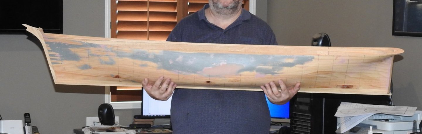
As promised here is the hull at 1/40 for size reference, I carved this one on CNC a while ago, I forgot I had it.
-
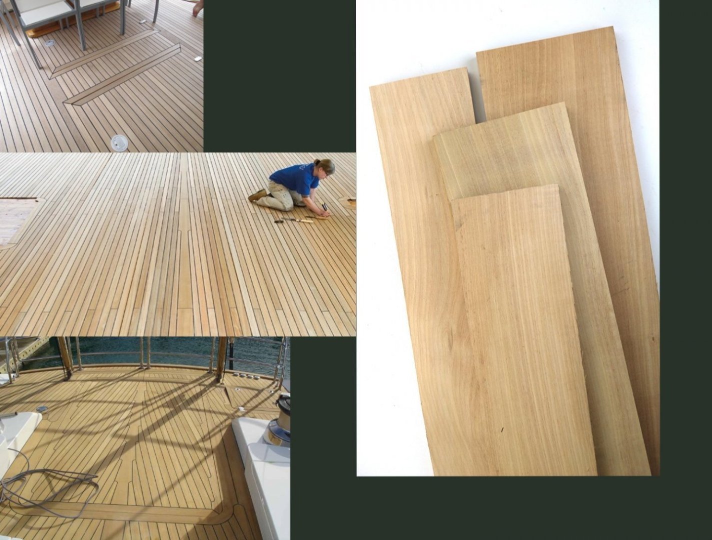
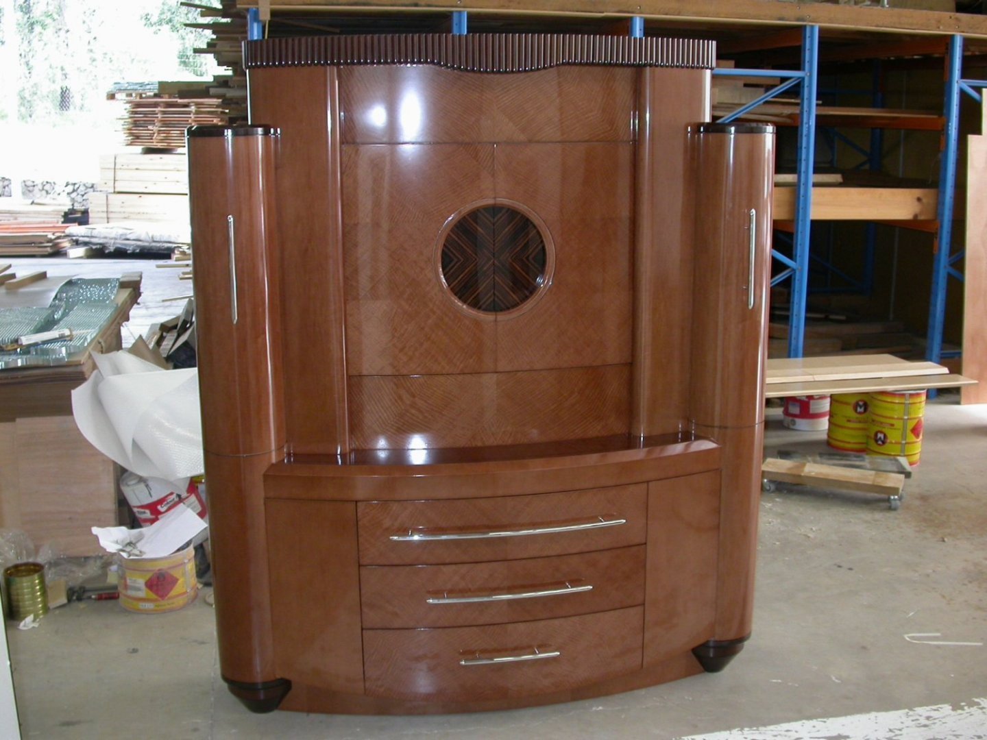
In regards to Anigre as a wood for teak decking, I have posted this somewhere else but since it is what I am doing for his I will post the image here to. I know my woods and have been a furniture builder most of my life and still build guitars. Anigre is not a high ranked wood but it is fine grained and nice to use, it does have an unpleasent smell..it smells like **** frankly.. but it goes quickly and becomes musty in smell, it cuts well and sands really nicely, it is fine grain with no large pores, about the same as Cherry. The issue is availability, if you can get it get as much as you can afford because it may not be around much longer due to bans on logging. I did some searching for it in the US and it seems easier to get for you. It is also readily available as veneer, be careful of this as its normally fiddleback with waves in it, its beautiful wood but no good on a deck. Here it is in veneer form on a cabinet I made 20 years ago note the figure which you don't want as you can see the colours match pretty well, the greyer stuff is good for older teak, for scale those planks are about 6 inches wide, the front one 4 Note the fiddleback figure in the venner! you don't want this if you buy Anigre veneer. By the way this was toned to this colour, it's not the natural colour.
-
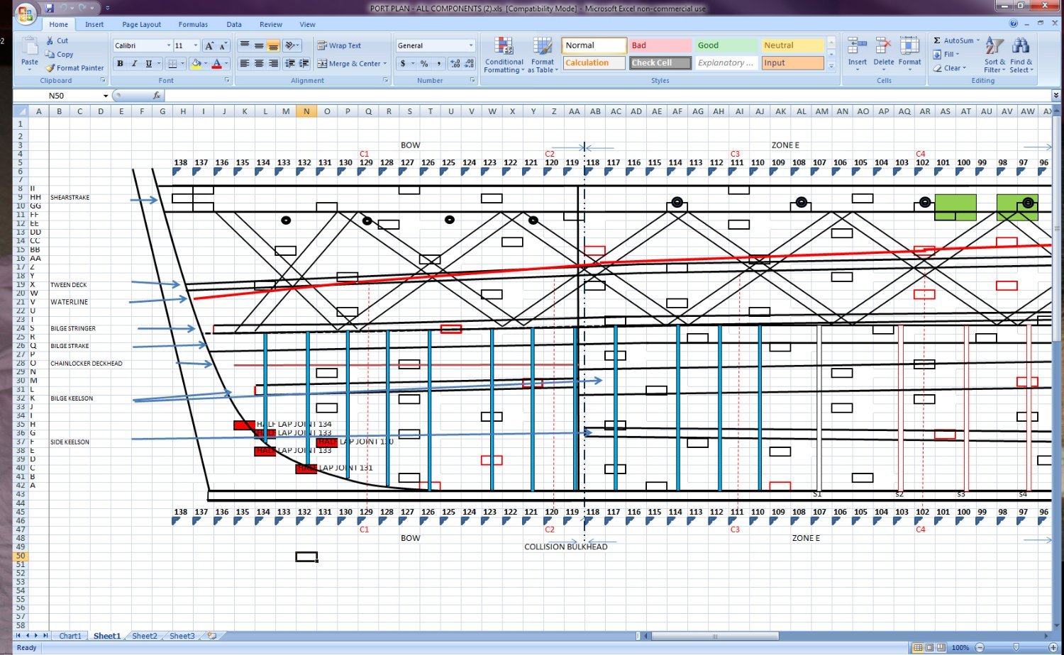
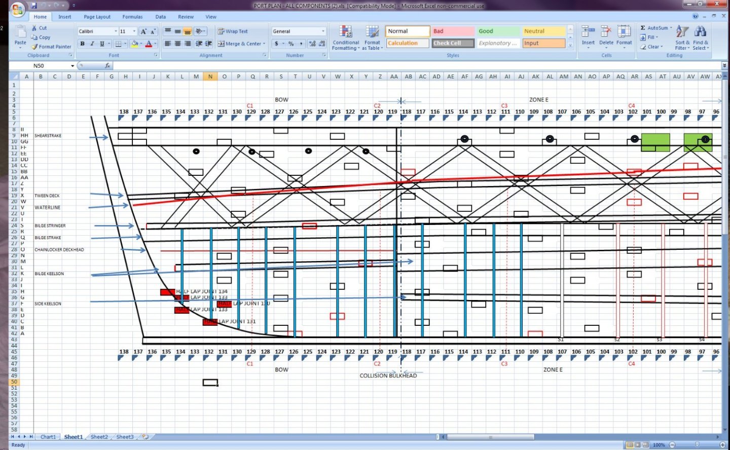
Here is how the planking strakes and butt positions were tracked, this is just a screenshot of the excel doc. the little rectangles are the butt plates. All in the name of absolute accuracy....nuts
-
I got a message about the counter planking , here is the planking next to the model and the nibbed sheer plank.
-
I carved a 1/40 scale Cutty Sark hull on the CNC last night so will post images of me holding it soon to show size
-
I do want to say I am not wanting to upset anyone or offend anybody with that comment, but it is true sadly. I could do a whole post on which plans have what issues and back it up with photographic evidence on every count but that might make me a target for trolls. I will say one thing though, the last set of plan I purchased were from a Dutch company and the work in them is absolutely spectacular, they are well presented and beautifully drawn...... BUT..... the guy who did them has tried to rationalise his decision to base his lines off the the Rennie midship plan, which was a preliminary plan and not "as built" , he has included all other body plans overlaid with that plan and pointed out why all the others are wrong compared to the Rennie plan, for those of you who are following this the Rennie midship has a drastic rise of floor that does not exist in the ship, photos of the ships bottom and frames prove this and he has taken a shot along the ships bottom from the bilge and interpreted the natural fall away and twist of the garboard as concavity in the rise of floor, its sad because he has done a beautiful set of plans but the drawings are not in any way accurate, the sheer line is low, and the counter is not at the right height either and of course the hull lines in general are way off due to midship being wrong. deck ties and diagonals are not in the right place either, by a long shot. I was most annoyed when I got theme. The only midship that is right is the C Jordan one as shown above, you can't argue with surveyed scan data. its as good as shrinking the ship and placing it in the computer The official Plans from the Cutty Sark are also approximate even by there own admission, they are based on recollections and previous plans. What has upset me the most is I have owned C Nepean Longridges book most of my life and viewed it as the bible but after working on the ship and measuring it first hand it's far from it, I am perplexed how some of the measurements are so far out, I can only assume some of the things he measured have been replaced to different scantlings from when she was afloat as a training ship. In saying all of this how many modellers really care about absolute accuracy? and just want to have fun, I personally could not go and spend over $1000 on a kit that has out of scale planking, wrong lines and even the waterline in the wrong place, the AL kit is the worst, it's not on in my opinion. I am going to do some plans based off the scan and you will be able to see for yourselves. I am just sectioning the scan, no interpretation is required, it's absolute
-
I will not be building this further than framing and planking, I have my 1/35 Wahine beast to do...now thats a big model
-
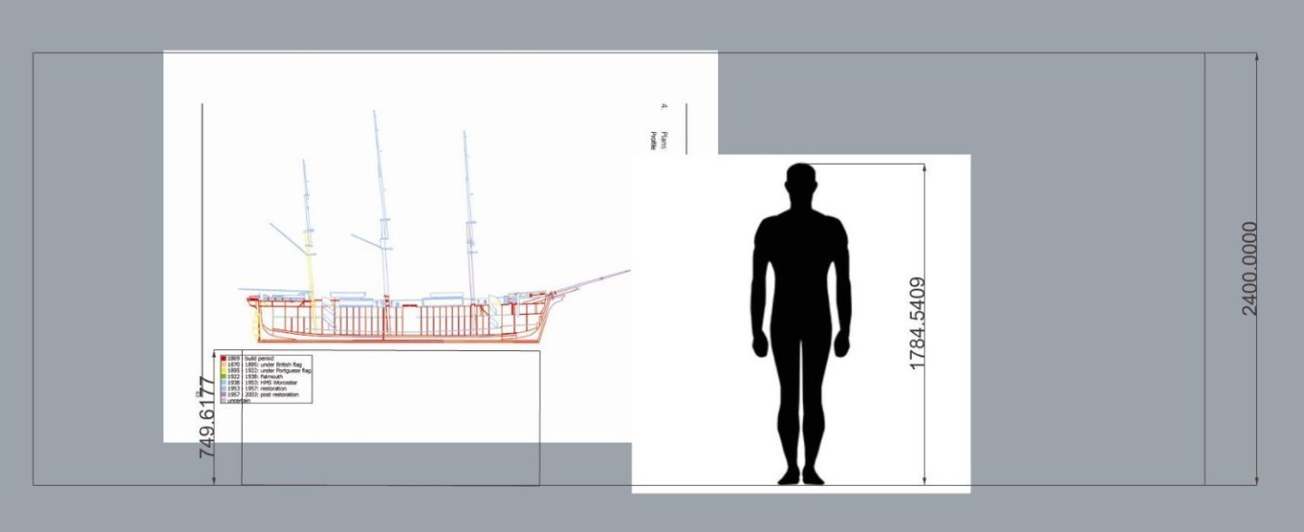
Plans yes, kit no, I don't go smaller than 1/48 the 1/40 was a specific request. The person this is for has foyer in his house with a 3.6m ceiling height, the height is not really the issue though its the beam of the mainyard at 600mm that gets intrusive really, the overall length is 2.1m approx the height is about 1.3m I think so even on a table it would fit most rooms....just but yeah still big. here is a drawing I just did within an 8ft ceiling, normal room height and a person, it's not THAT big really. and that's sitting on a table 750mm height with room to spare