HOLIDAY DONATION DRIVE - SUPPORT MSW - DO YOUR PART TO KEEP THIS GREAT FORUM GOING! (Only 20 donations so far - C'mon guys!)
×
Richard Dunn
-
Posts
529 -
Joined
-
Last visited
Content Type
Profiles
Forums
Gallery
Events
Everything posted by Richard Dunn
-
 That makes perfect sense so in theory I should be able to see that on the foredeck in aerial photos.
- 454 replies
-
- 1
-

-
- Union Steamship Company
- Stepcraft 840
- (and 3 more)
-
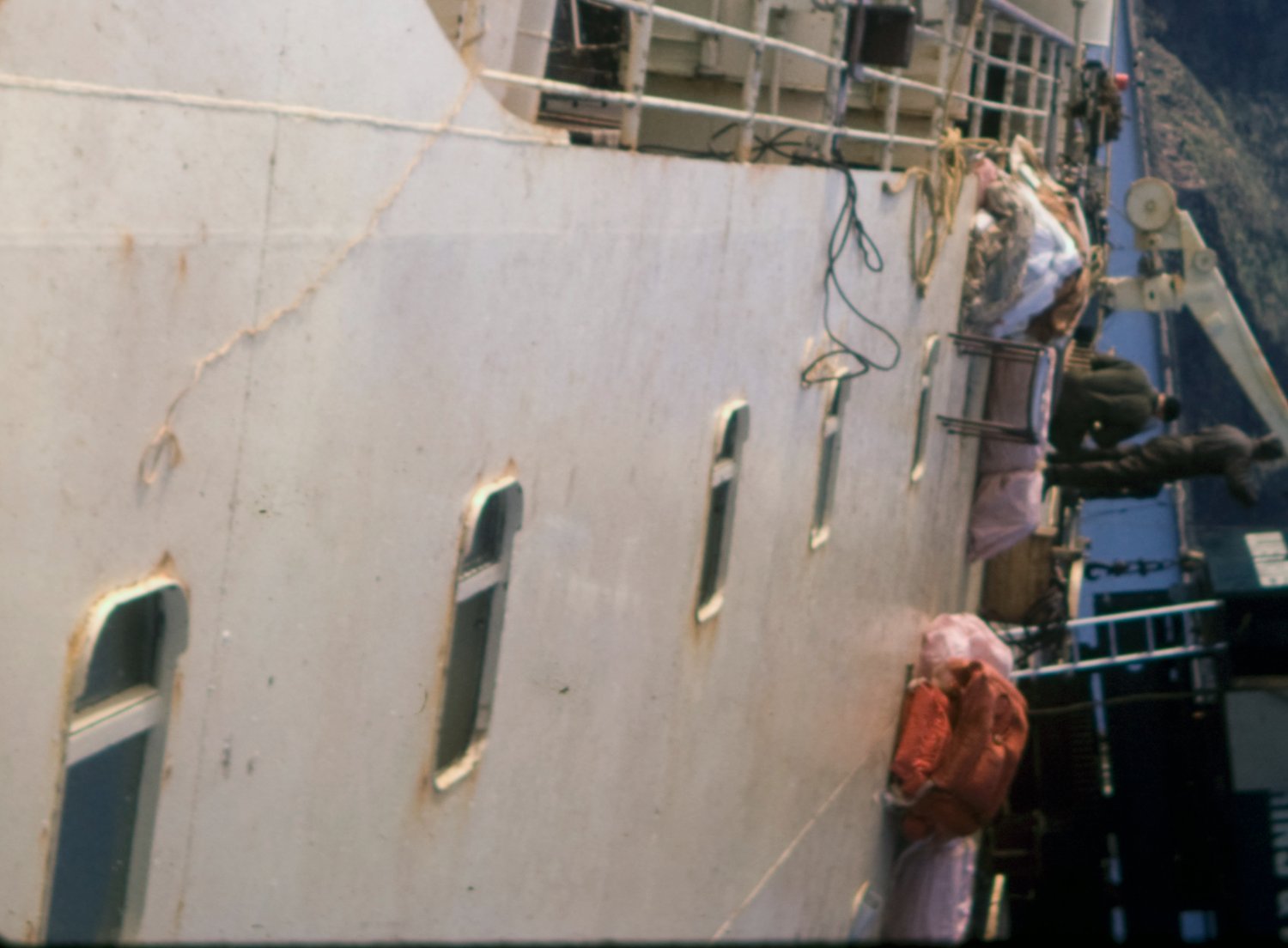
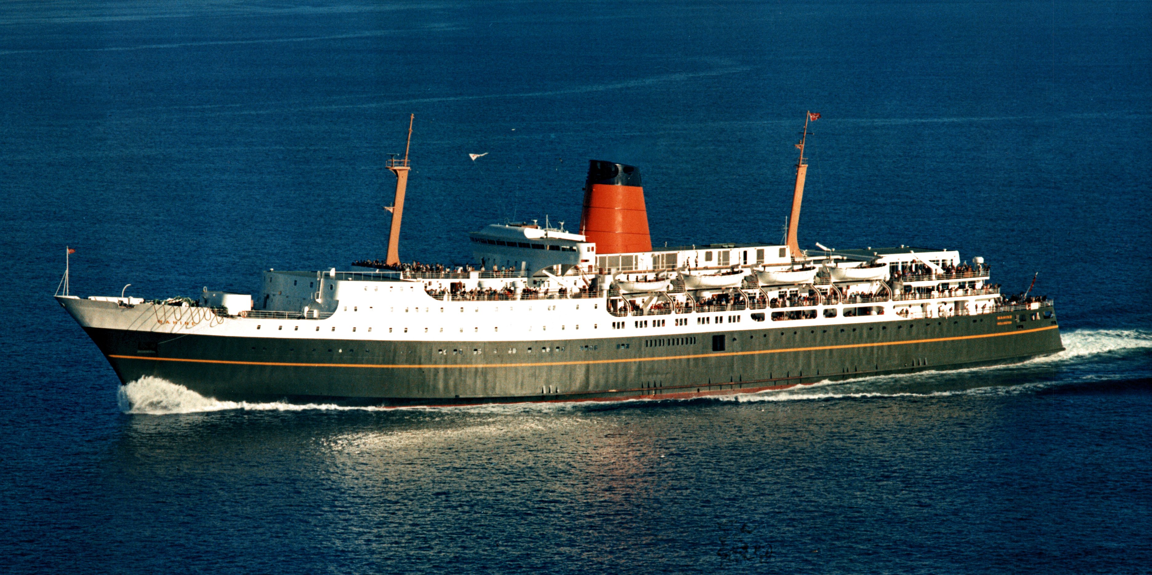
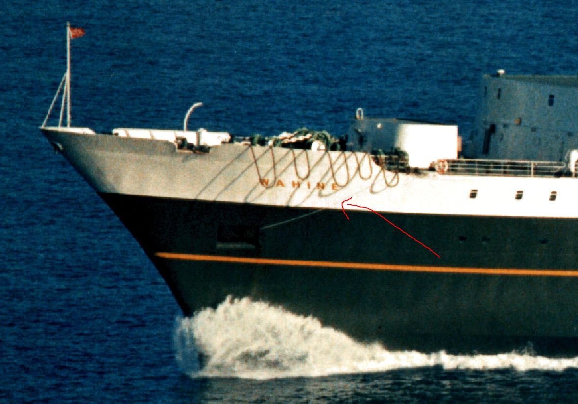
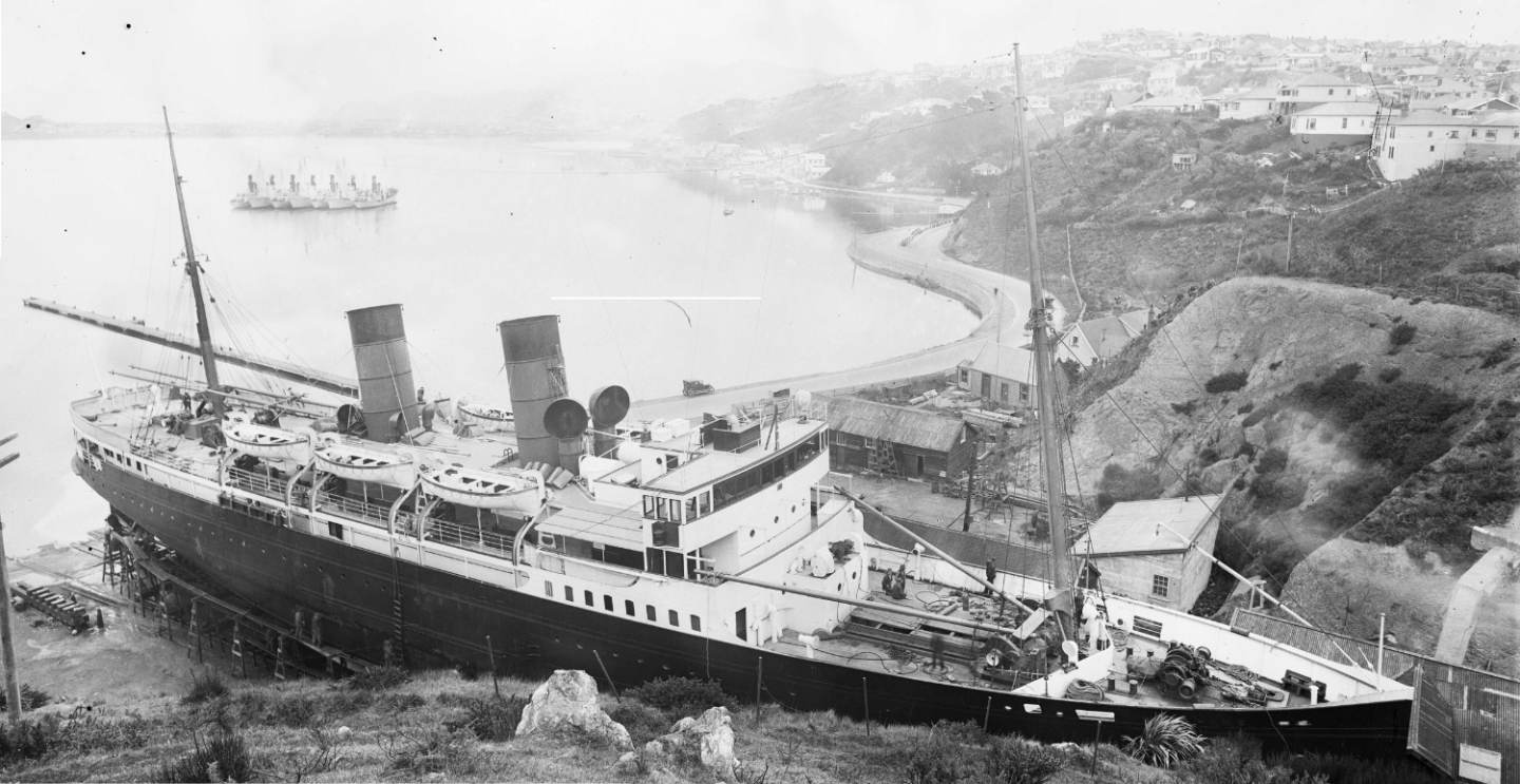
Hopefully someone can answer this question. What is the function of this line?, it's on both sides of the ship when she is in service. It seems to be steel cable in better images. It clearly goes into the anchor recesses and I assume up the hawse.
- 454 replies
-
- 1
-
-
- Union Steamship Company
- Stepcraft 840
- (and 3 more)
-
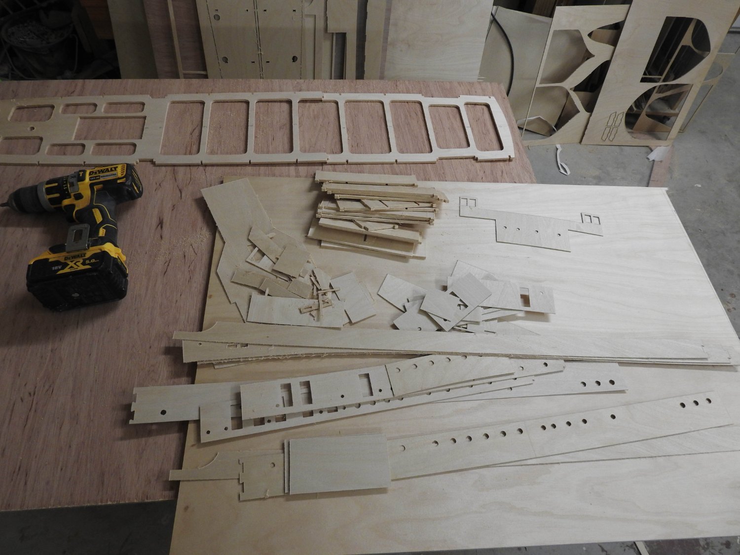
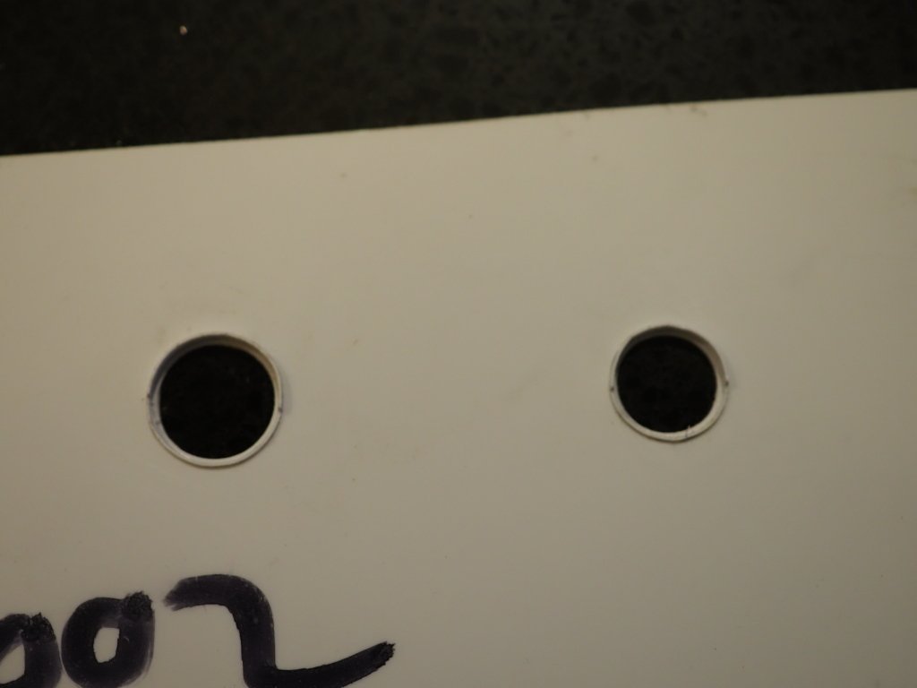
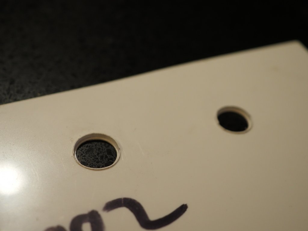
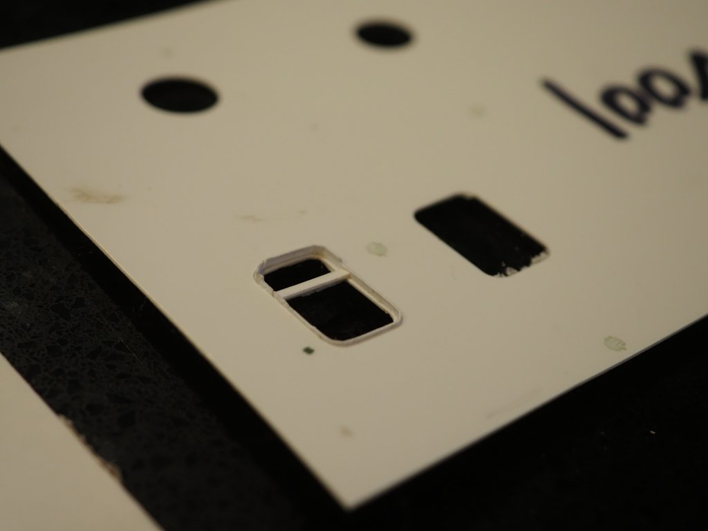
Today I prepared the files for making all the deadlights and portholes. the window itself is cut out and must eventually fit into a precisely cut opening in the plate with no gap and no pressure needed, the window is then put into an aluminium jig and the outer frame and rigol bent into the jig and once the ends are in place it holds itself up against the outer edge of the jig, once a light application of styrene glue is applied it can be taken out of the jig, the transom of the window glued on and it can be painted ,glazed and glued into the actual plate before being glued to the model. Here are the first tests I did, 14" and 16" portholes, the deadlights frame needs to be dipped in hot water and pre bent around a former before being put into the jig as you can see here at bottom it started to fragment while being pushed into the corners. And the rough semi broken frame but the process will work, only 270 to make....... I could cast them in resin but want the advantage of a solid weld betweeen the frame and plate so by using styrene I get that. Also I have found a very very believable way to do the frame distortions and it is super easy and it looks amazing!, I will cover it soon once I get some plates on the model.
- 454 replies
-
- 8
-
-
- Union Steamship Company
- Stepcraft 840
- (and 3 more)
-
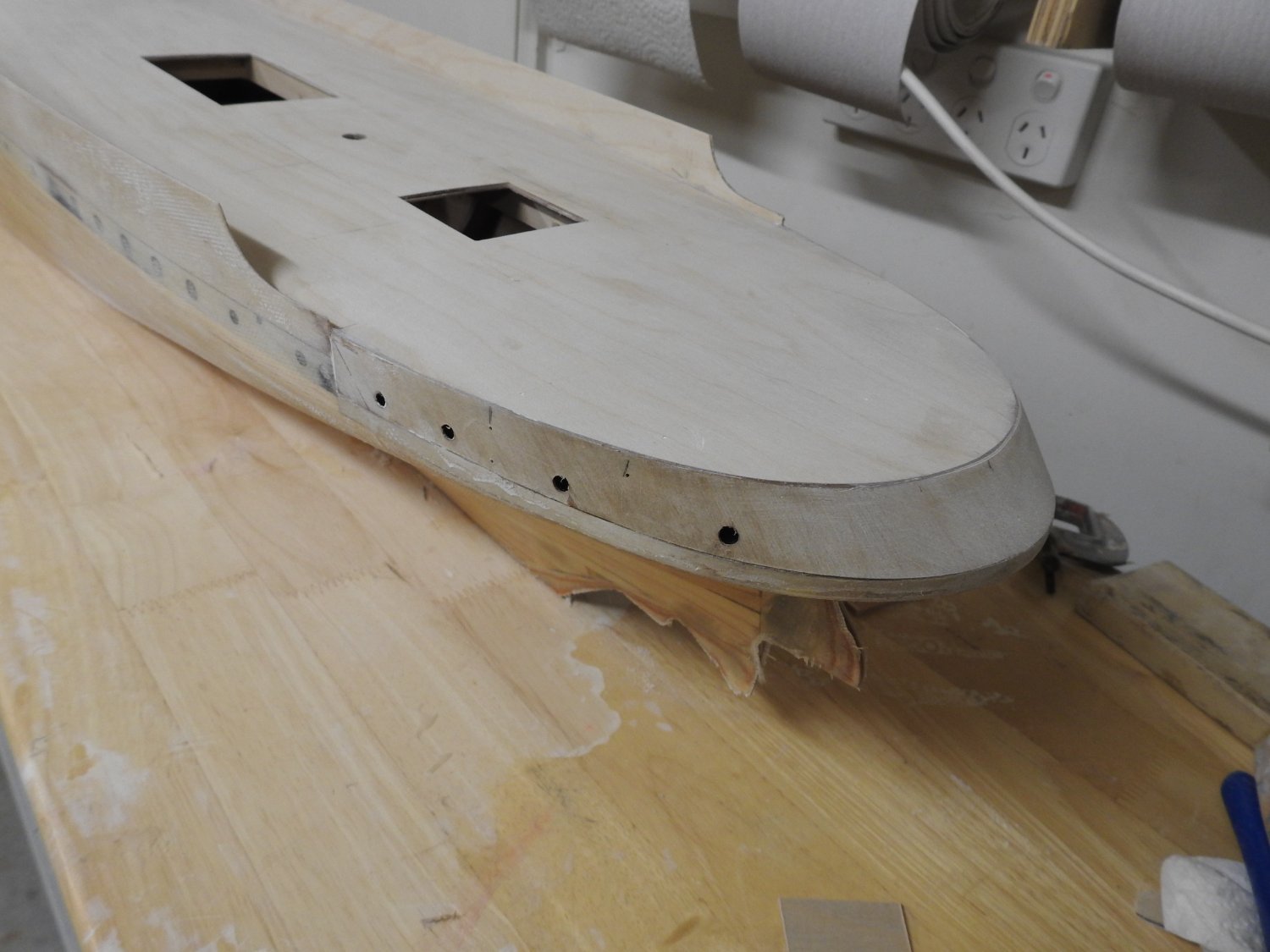
Deck installed and cleaned up ready for laying of deck around superstructure. Also the counter is finished ready for sanding and plating.

- 46 replies
-
- 11
-
-

-
Yes but why struggle with drilling metal when is painted anyway?.. Plastic would be far easier on pin drills.
-
Yes they do but as I pointed out in the first post earlier, nobody does 4 ball or 3 ball with wood top rails Stanchions. and the 2 I have found are not in the right size. I have looked all day and am hoping to see if someone has a niche market making them or something like that that is not mainstream.
-
Thanks for the replies guys. I had searched for articles before posting but Stanchions does not find that much so thought I would ask. I think the article on Okesa might be the closest to my needs as I can find . I like the photoetch idea as well but think it's potentially too much clean-up. I am going to try the technique in the Okesa build, shame the images are not big enough to see but anyway, going to solder the rail and stanchions in a jig after making half depth slots in the stanchions and then making a jig to grind half a 1.5mm plastic ball off and another jig to cut a cross on its flat face and glue 2 of those over each joint to form the ball using these. making the half balls is really the only hard part https://www.aliexpress.com/item/1005002261984898.html
-
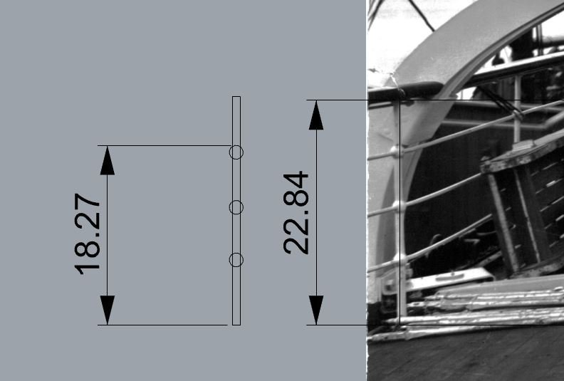
Does anyone know where I can buy stanchions of this type?, I have searched and searched online but not found anything suitable for this scale I need 130 of these in the dimensions of 23mm deck to rail with 3 balls bored for .5 mm wire. Main stanchions .8 mm optimally, with 1.4 mm dia balls. It seems this scenario has been completely left out of most catalogues. I am considering making these out of half round brass wire and doubling them over and pressing them between a steel press to form the balls. Anyone tried this? The height can't be altered as they carry on from Bulwarks.
-
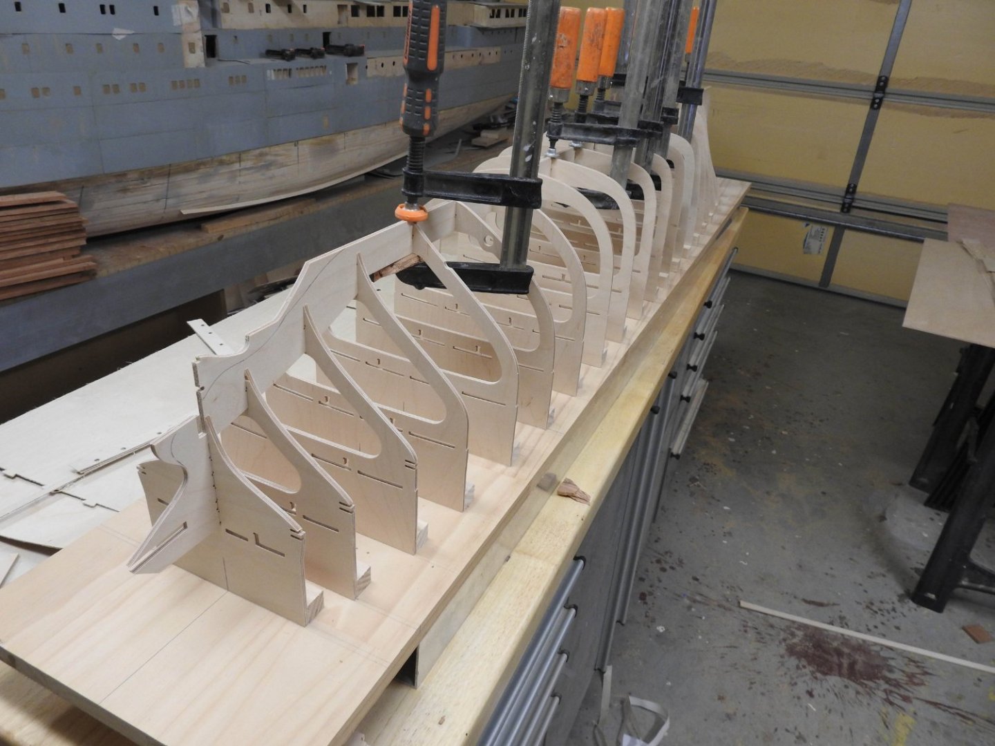
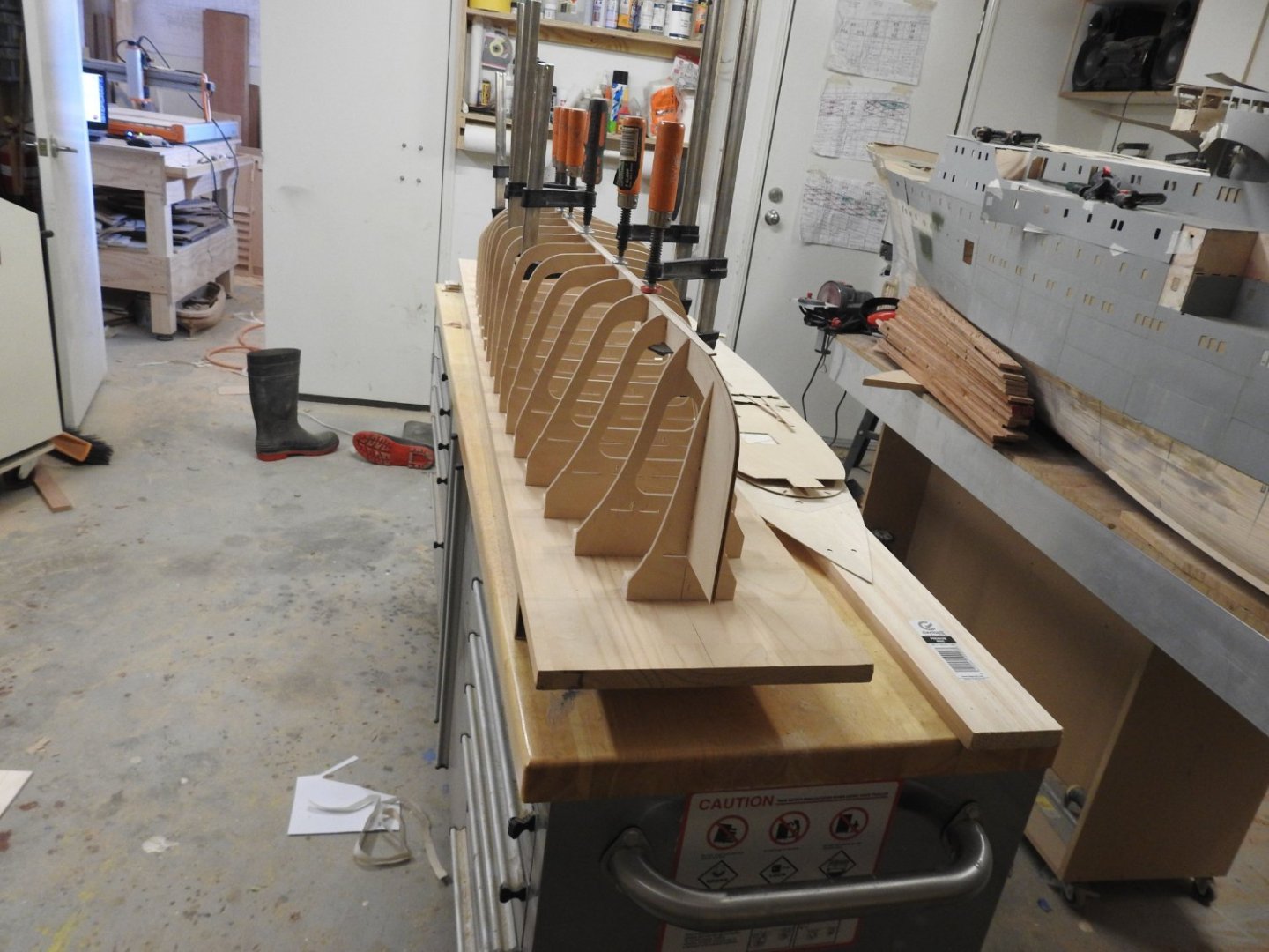
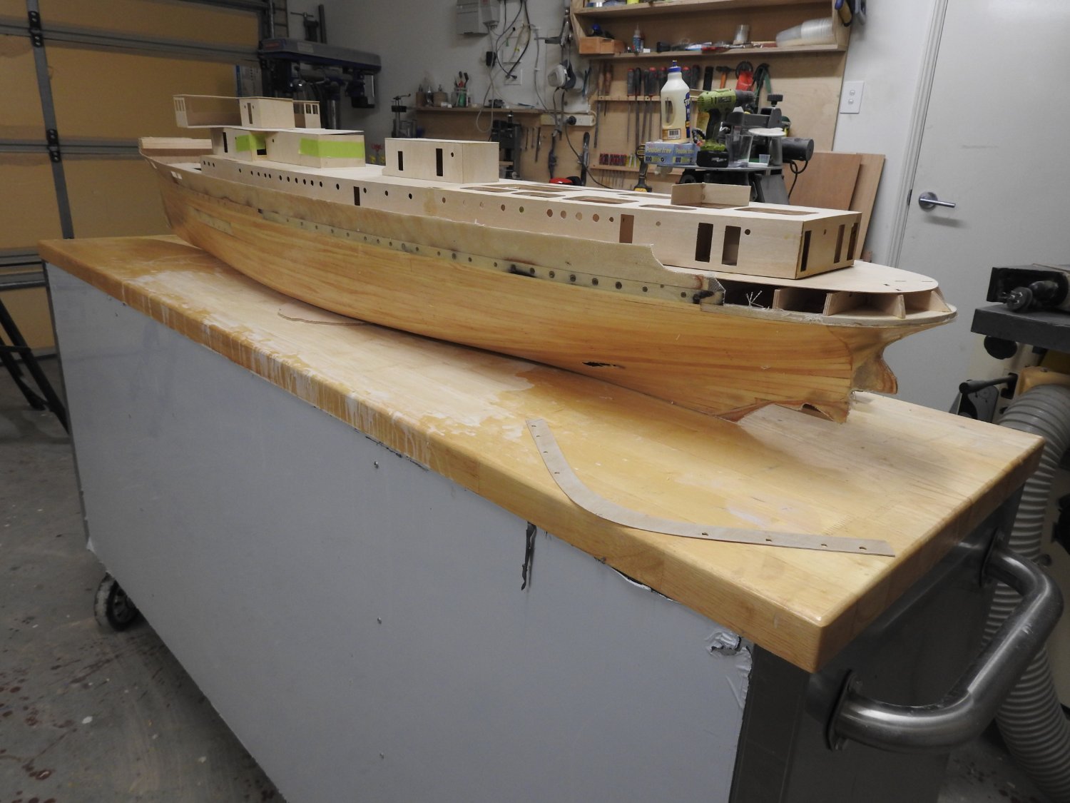
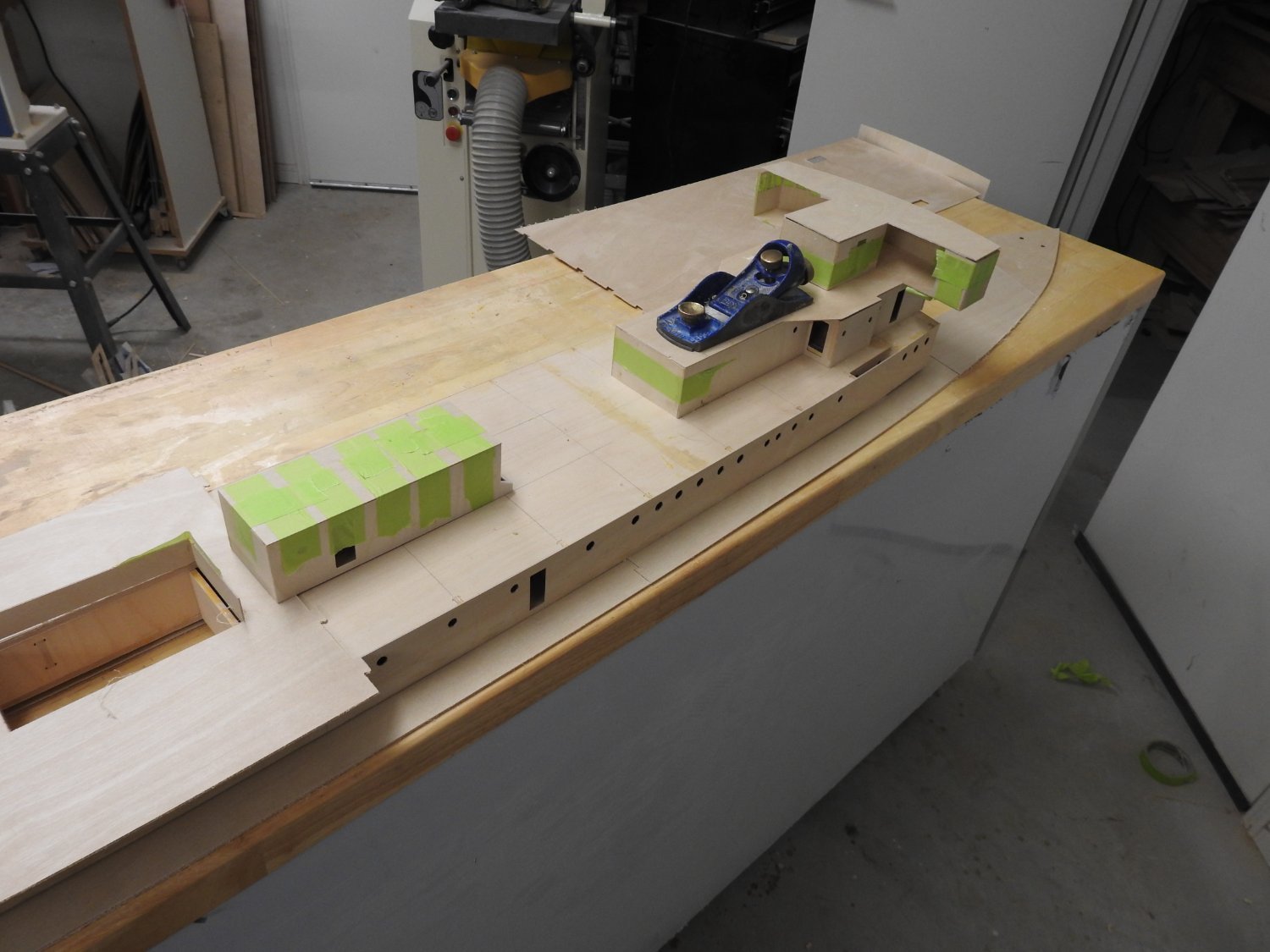
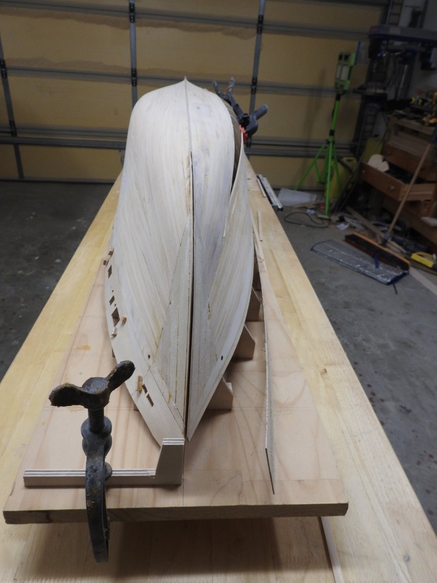
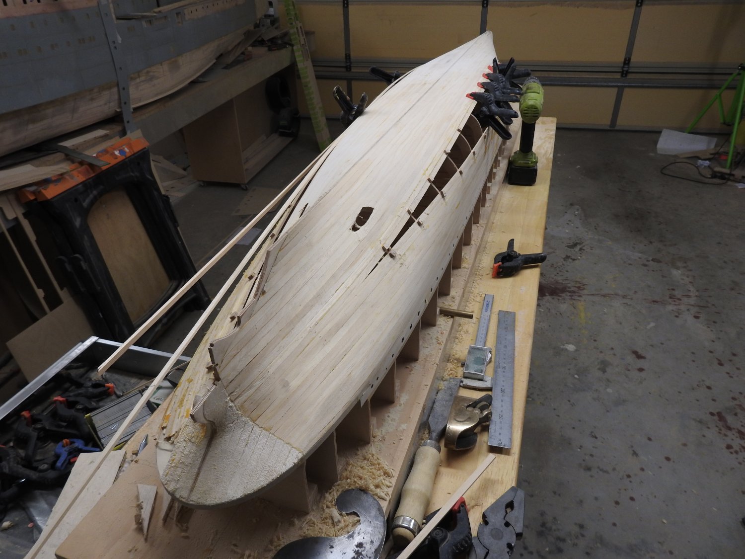
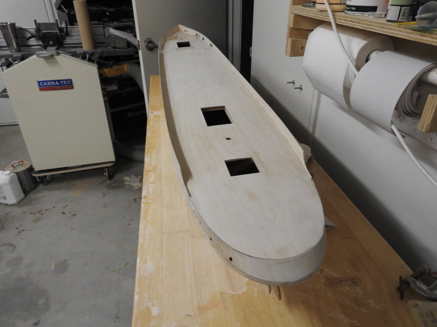
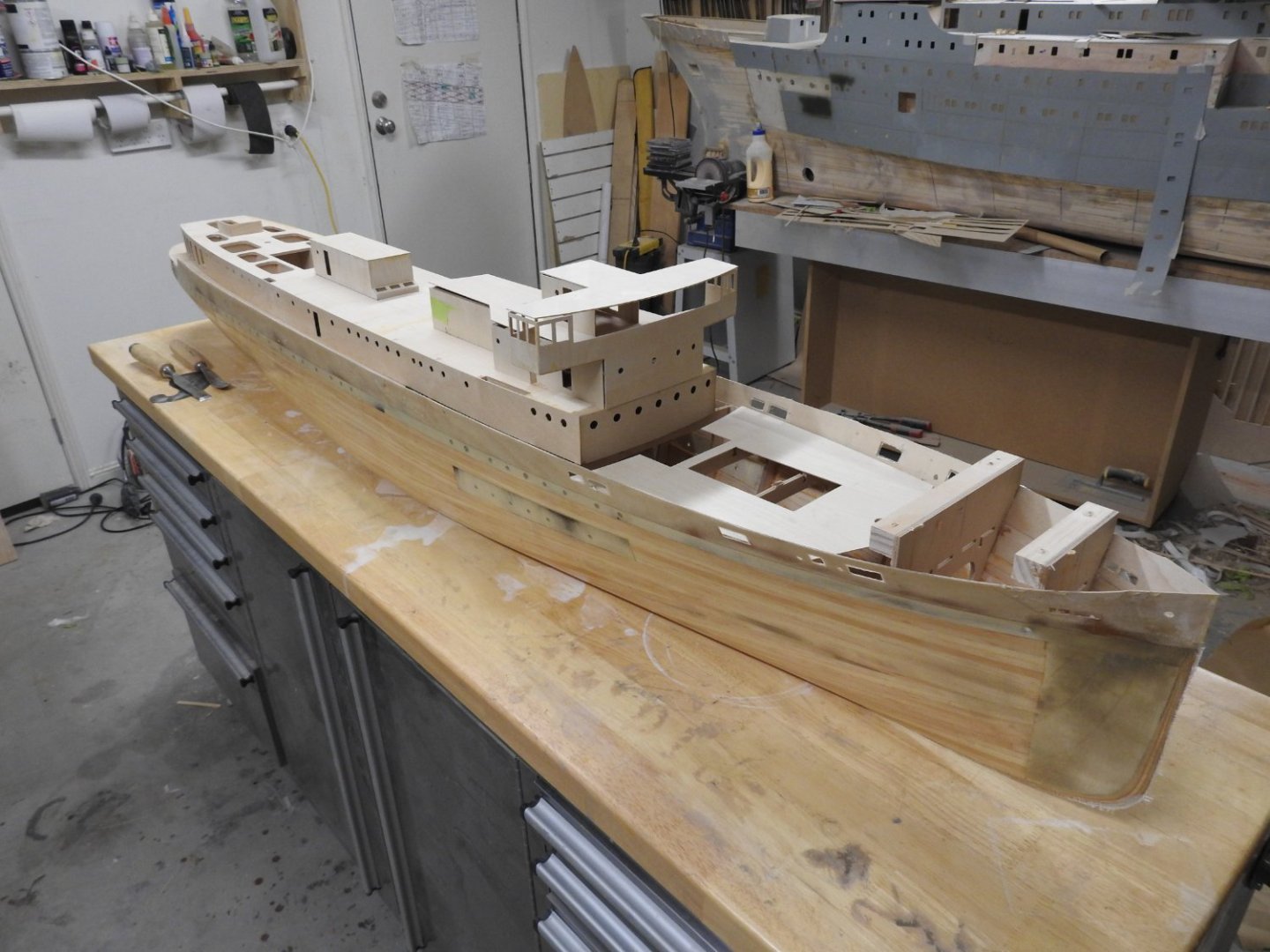
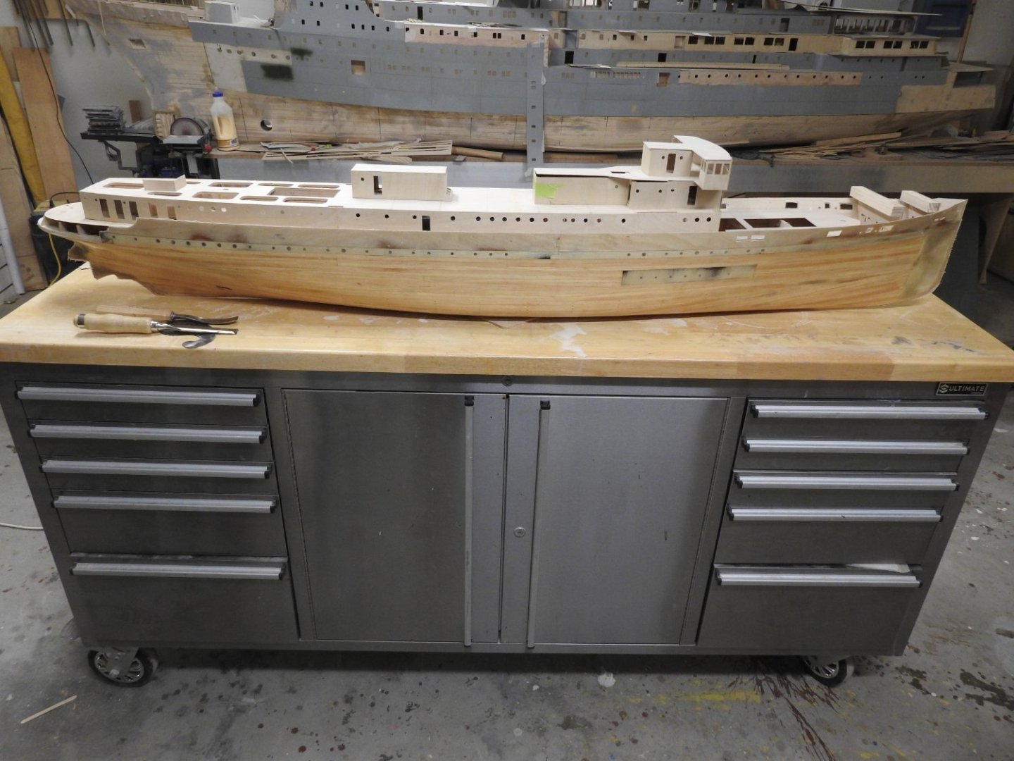
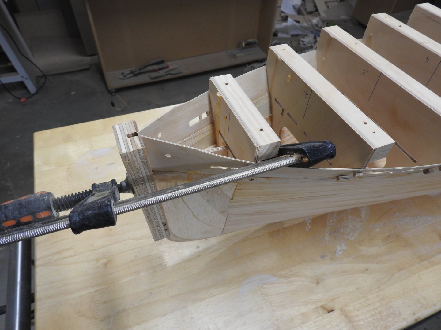
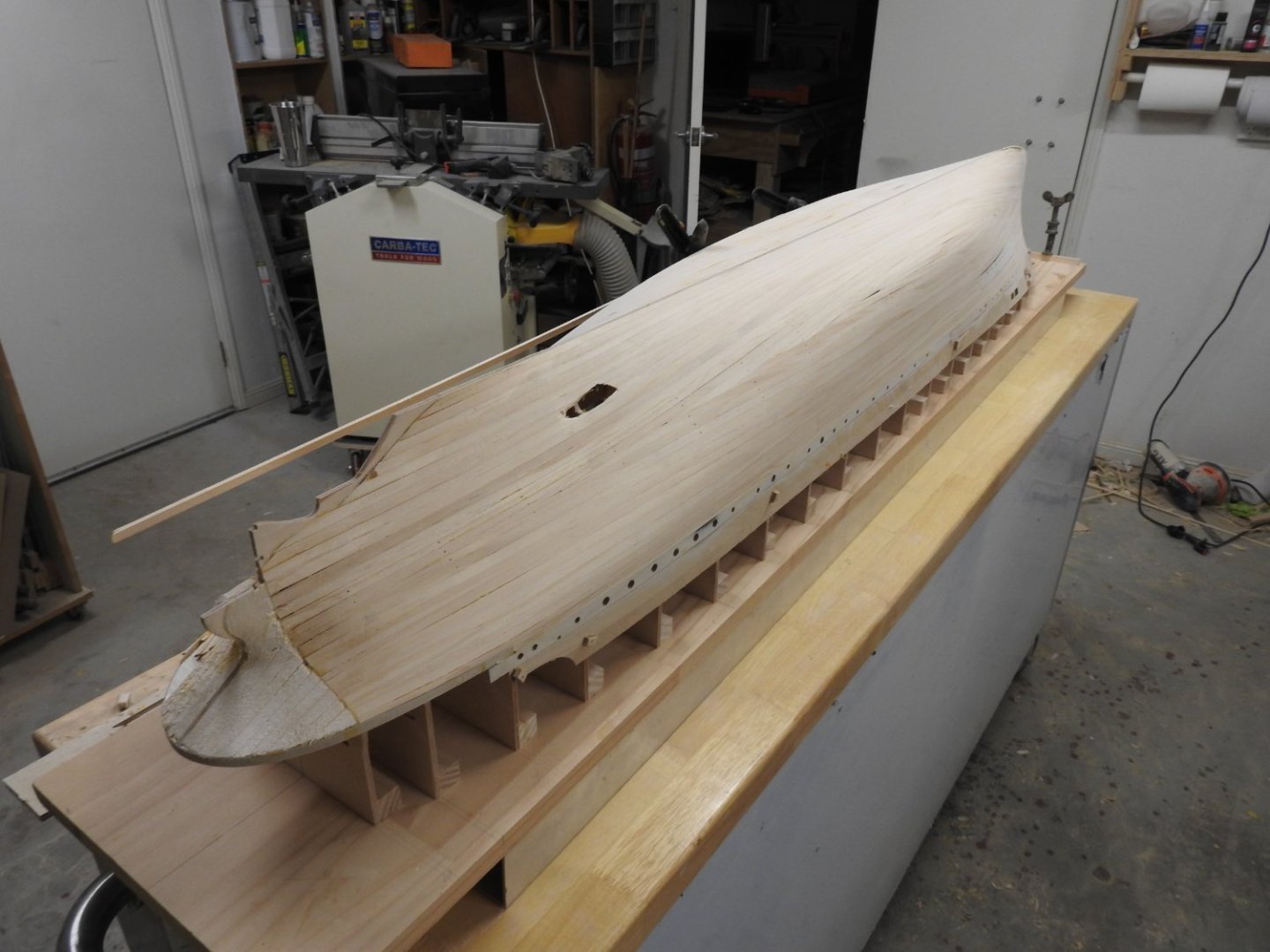
Well I had to sit everything in place once I cut all but 2 frame extensions off to get a sense of the size. and weight,, BTW I can lift it with one finger.

- 46 replies
-
- 10
-
-
-
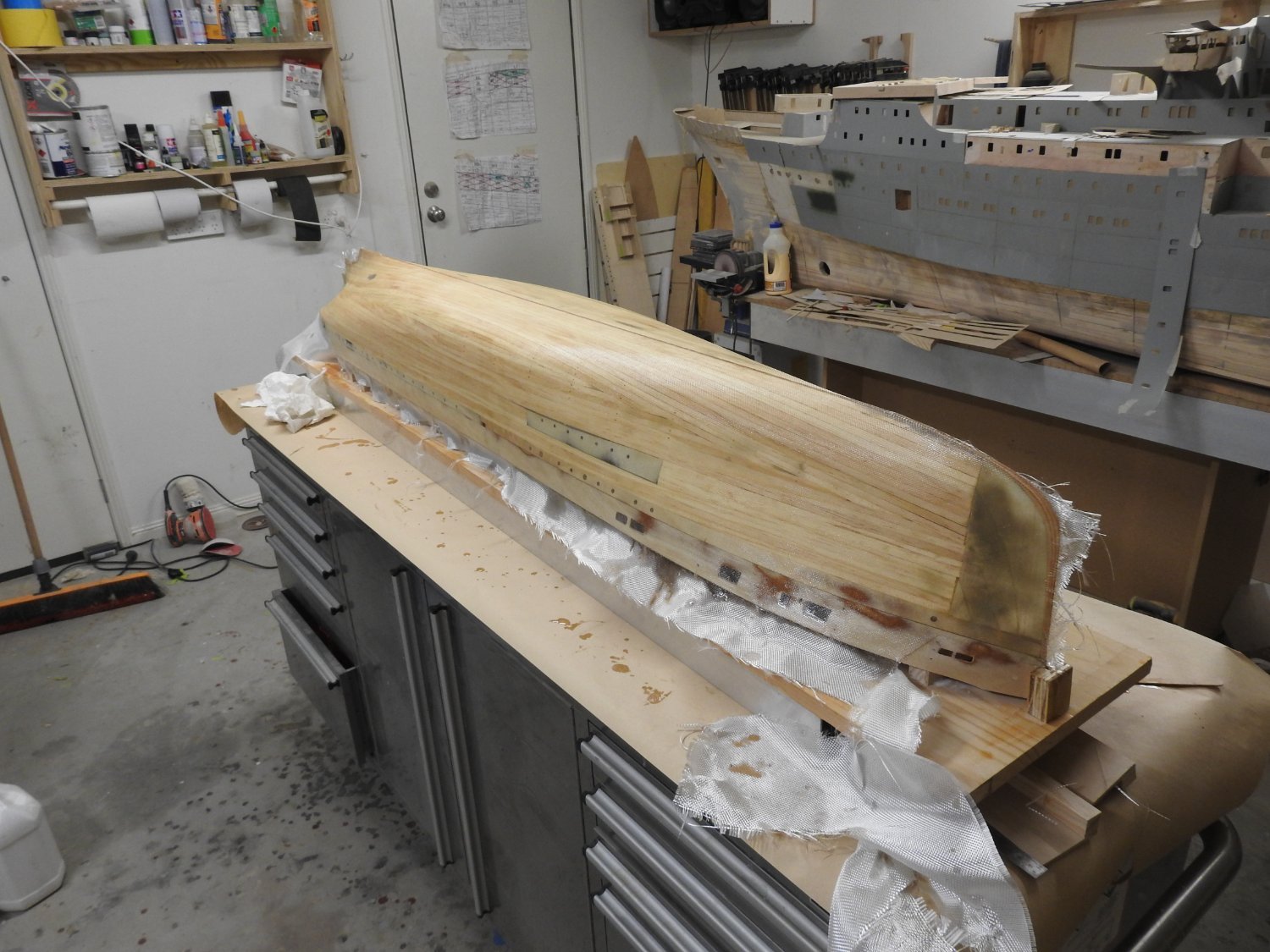
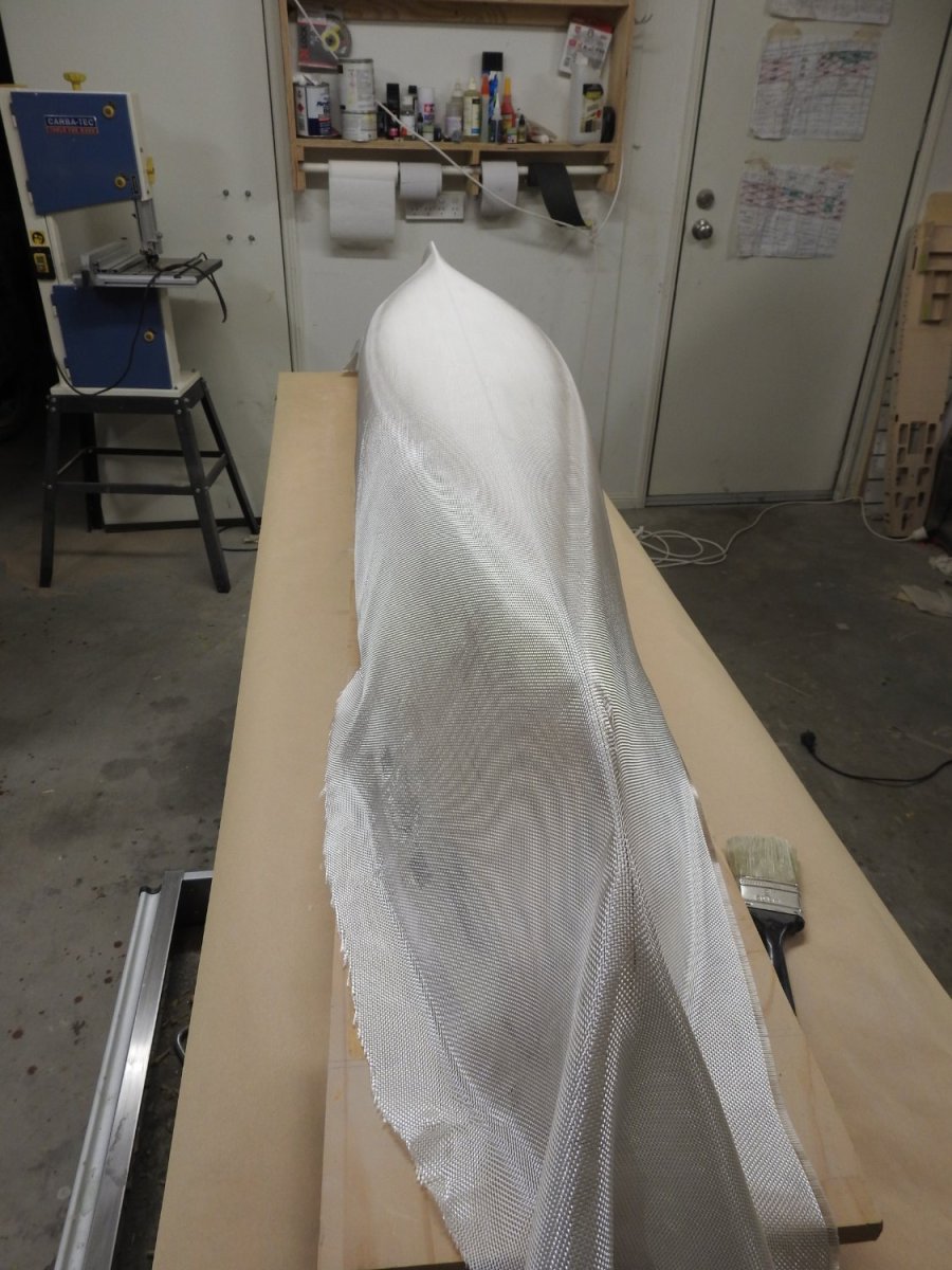
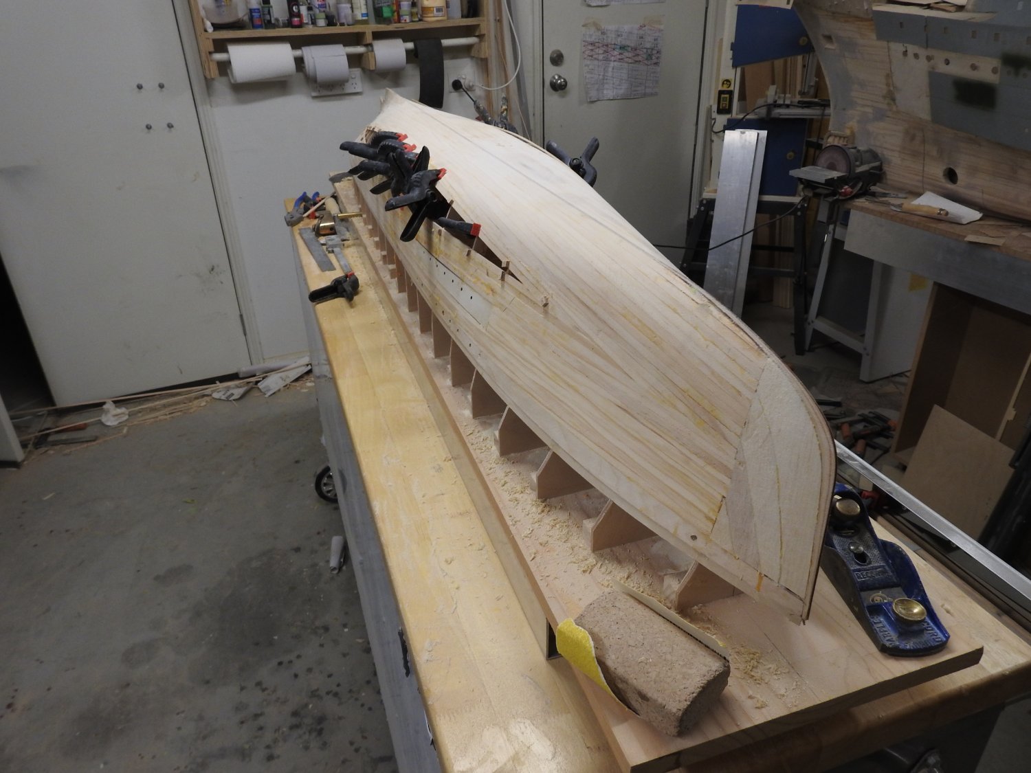
Correct, it's quite a light weight 25gsm woven cloth so as to not add too much thickness to the hull, its planked with 2mm pine but by the time its sanded what you lose the glass puts back. This is normal for glassing practice for small boat and canoe construction, after an hour of curing for the first coat, once its soft but setup you apply another coat and screed it on with a plastic or rubber blade to "Fill_the weave" This is now done and ready for a light sand and priming with high build primer. I did not need to fair this hull and fill and sand low spots at all because the 3d model was spot on and as such so were my frames. This Easter is the horrible job of cleaning the glue out inside that squeezes out between the planks and glassing in between each frame. If anyone has any interesting tricks or gadgets for this I am all ears. I hope to have the Main Deck installed by Monday night.
-
Ready to wet out in the morning. What are peoples thoughts on plating materials? On one hand copper or the other Styrene sheet, I am thinking styrene glued onto the hull with Cyano since its lapped buts on both inner and outer strakes. Much like the plating in RMS Titanic: A ModelMaker's Manual by Peter Davies-Garner

-
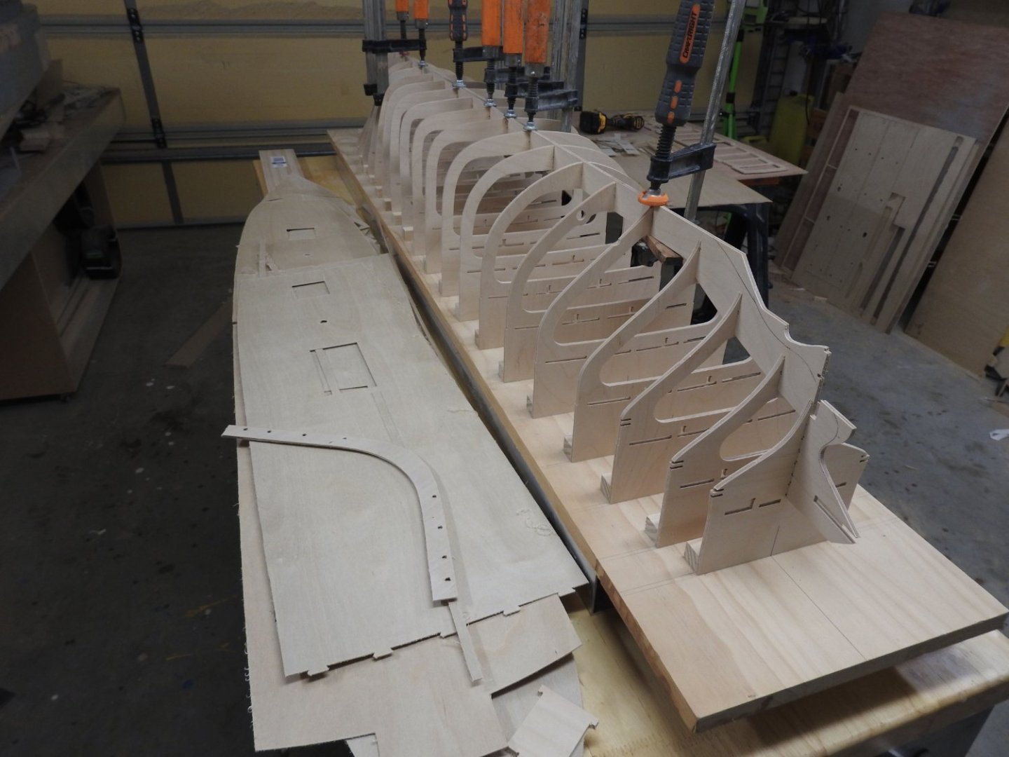
Bulwarks glued into hull and frame extensions starting to be cut away. Now the horrid job of cleaning up the glue from inside before glassing. which is being done to both sides of hull, hull will be plated with cooper shim

-
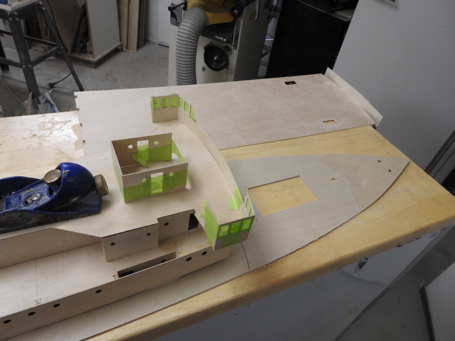
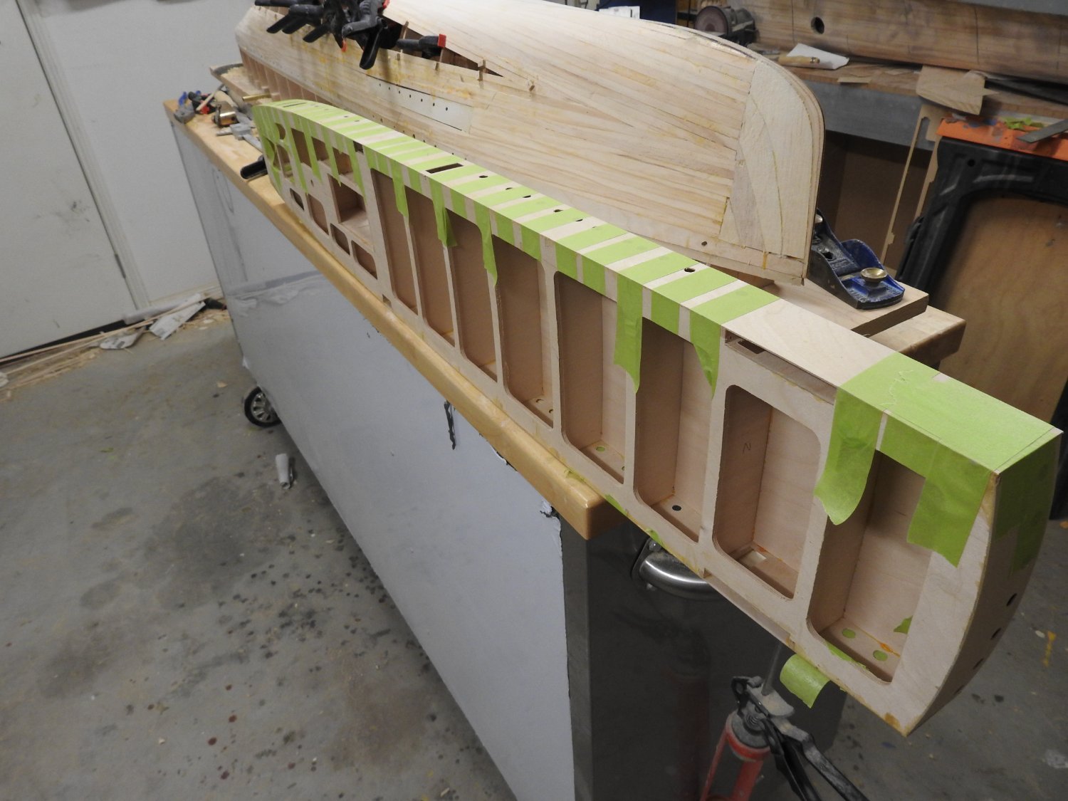
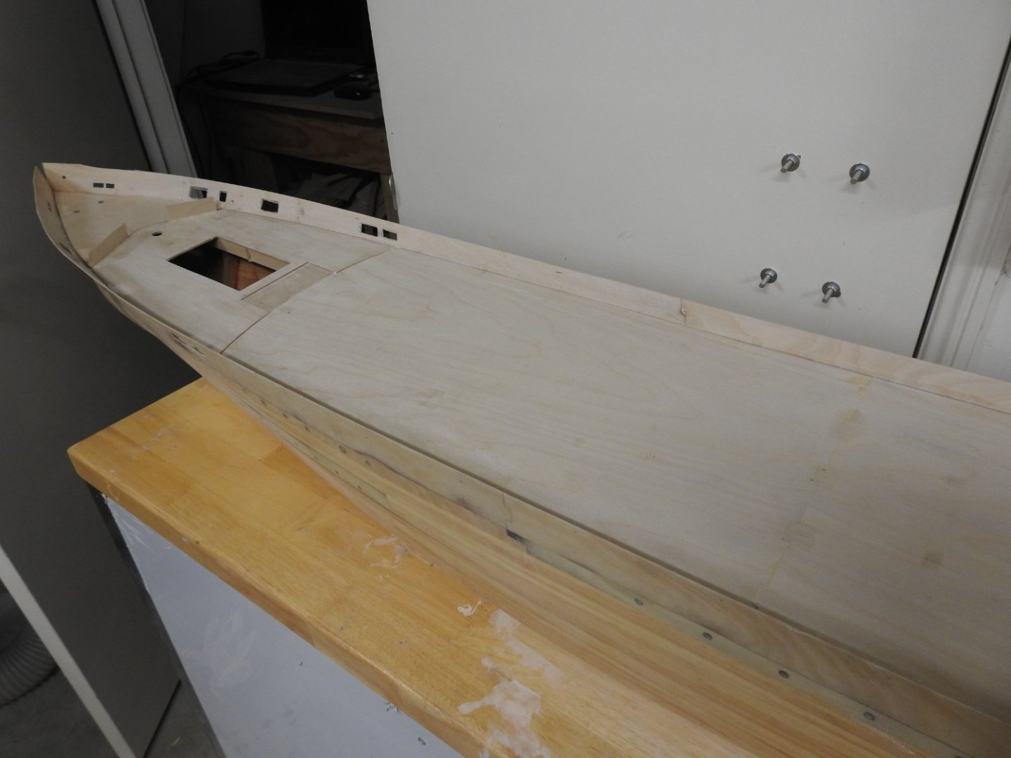
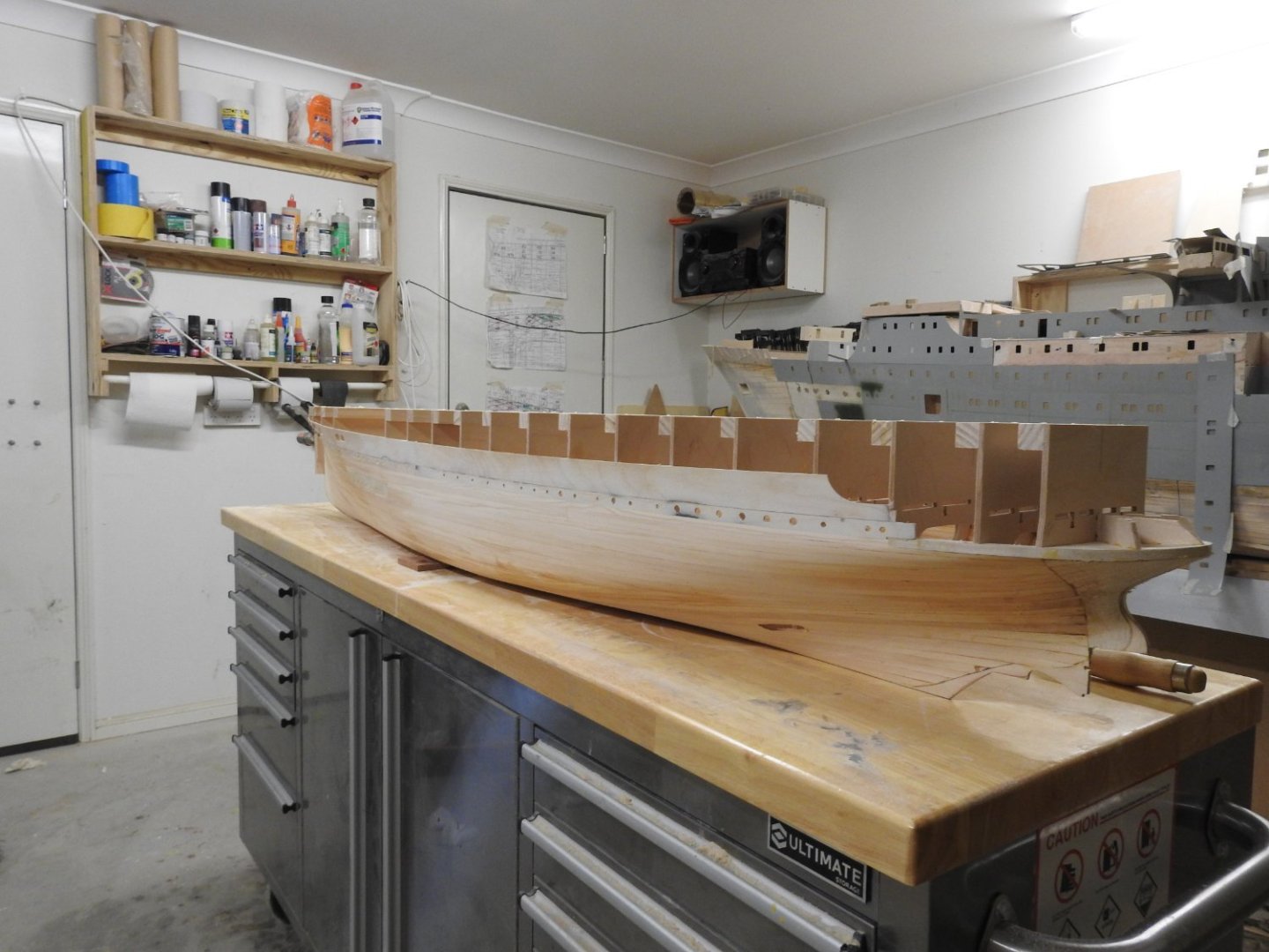
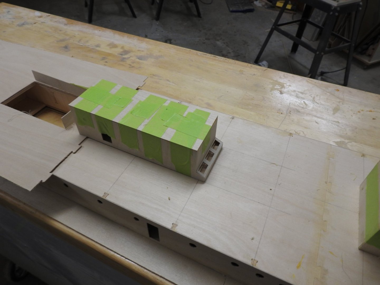
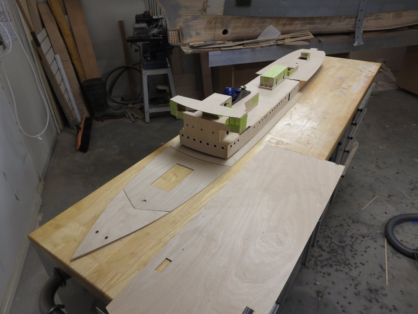
The hull is now closed in and sanded ready for glassing, that might be an Easter project I think. I thought I would put up some images of the Superstructure in its simplicity, yes this all there is to it minus skylights and hatches etc, but a far as structure goes its sooooo simple. The below shoes the deck after forming the promenade but its not fitted forwa4rd as currently the wheelhouse unit is temporarily screwed down to keep the camber. The forward section is in the foreground.


- 46 replies
-
- 10
-
-
No luck with Arawa or Tainui
-
Yeah I expect at some point the lines plan will turn up, but a lot of this is still being sorted, I recently went in to help with some sorting a few weeks ago.
-
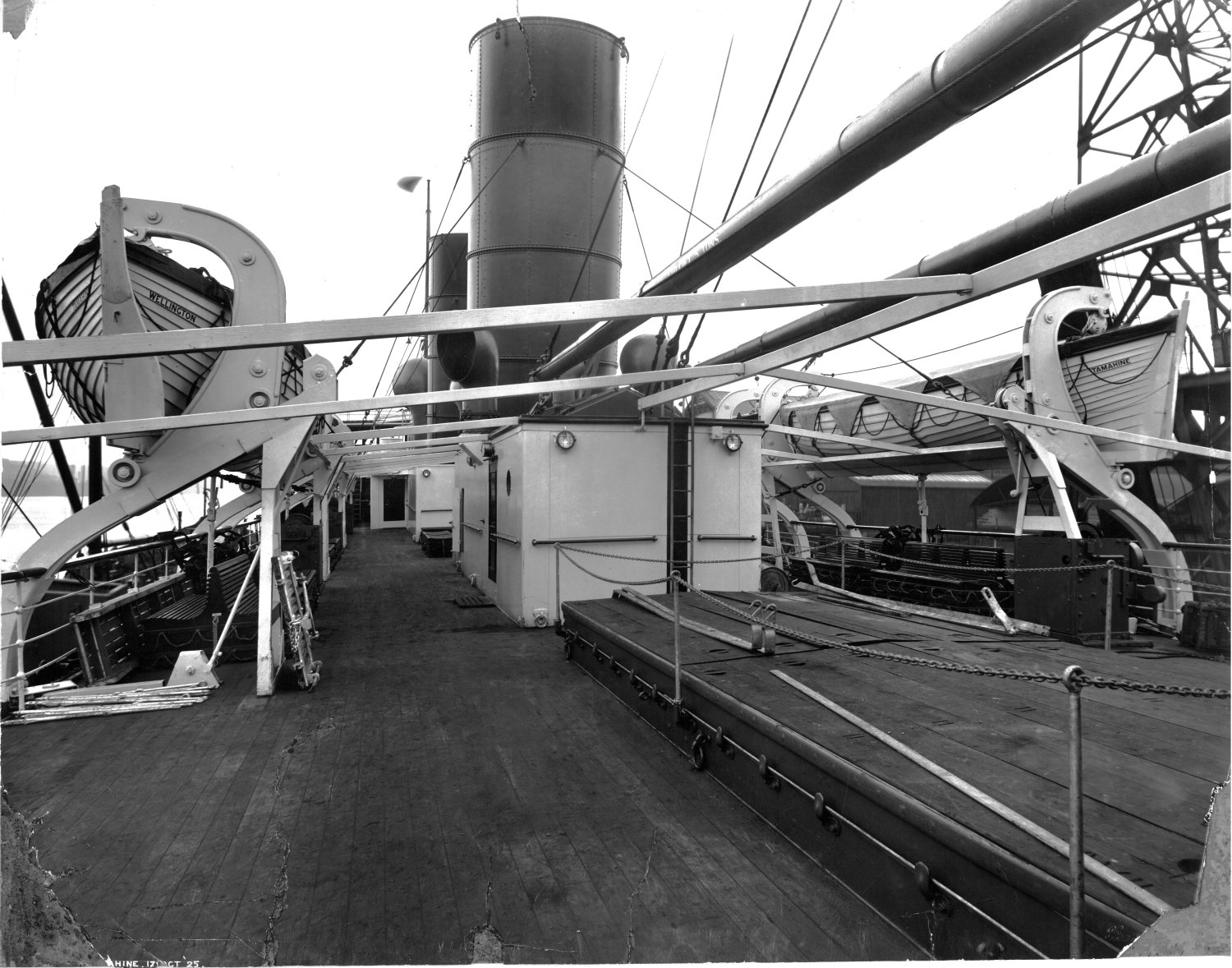
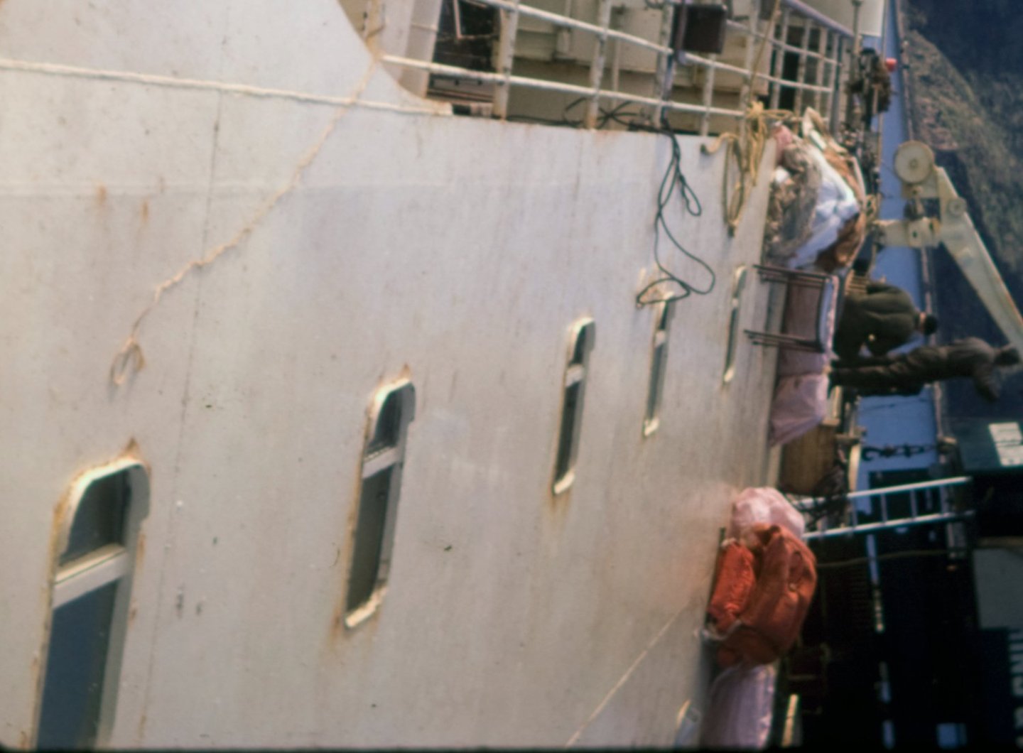
Thought I would share this image as its one of those amazing detail shots we model makers love, this is not full res but the Bulwark in the above shot can be clearly seen.
-
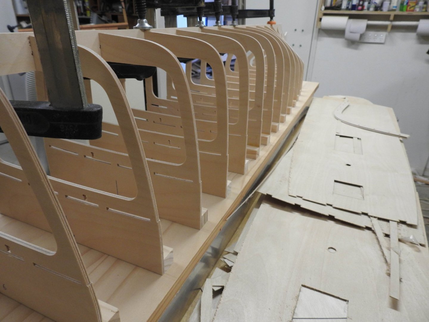
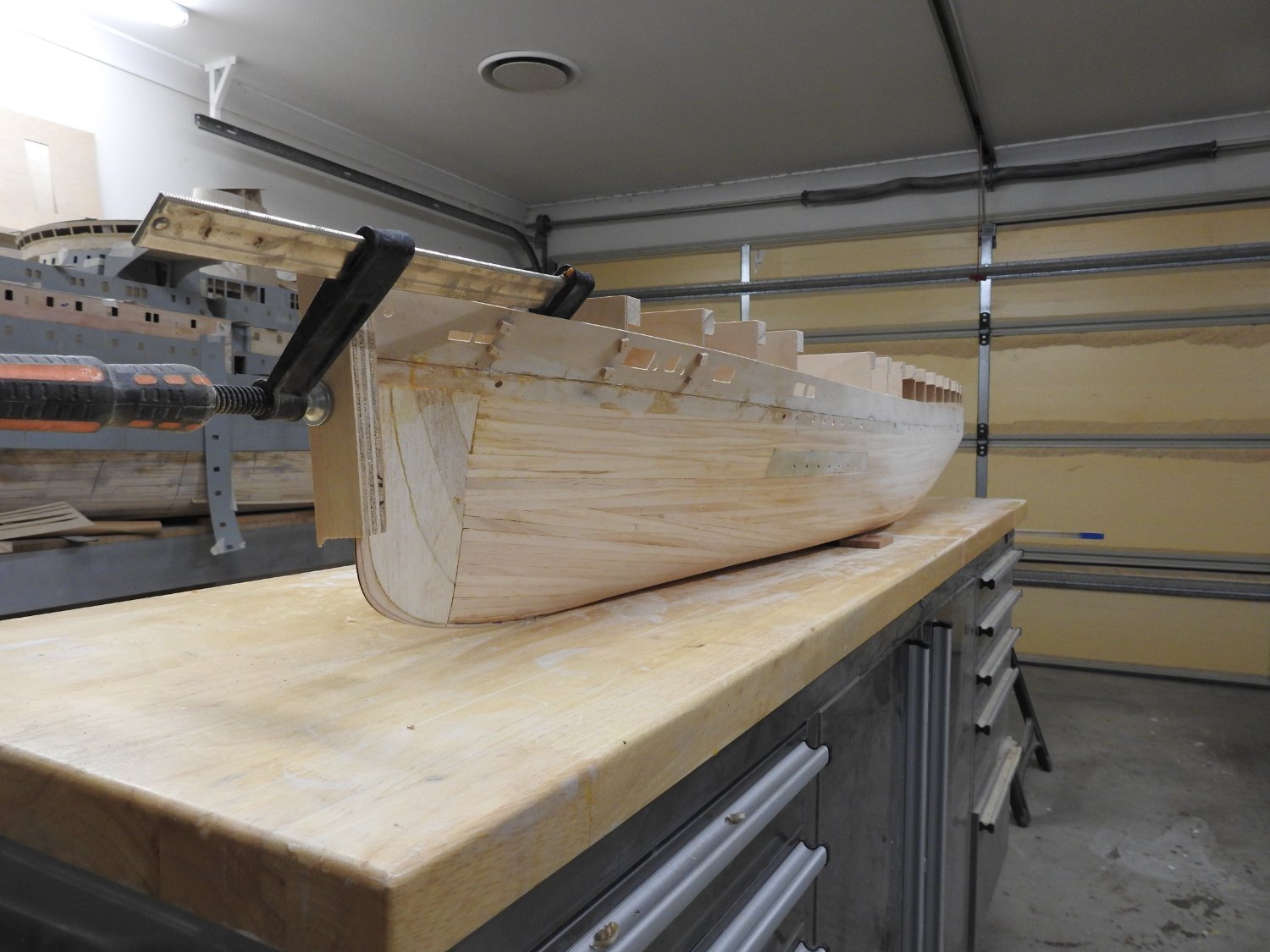
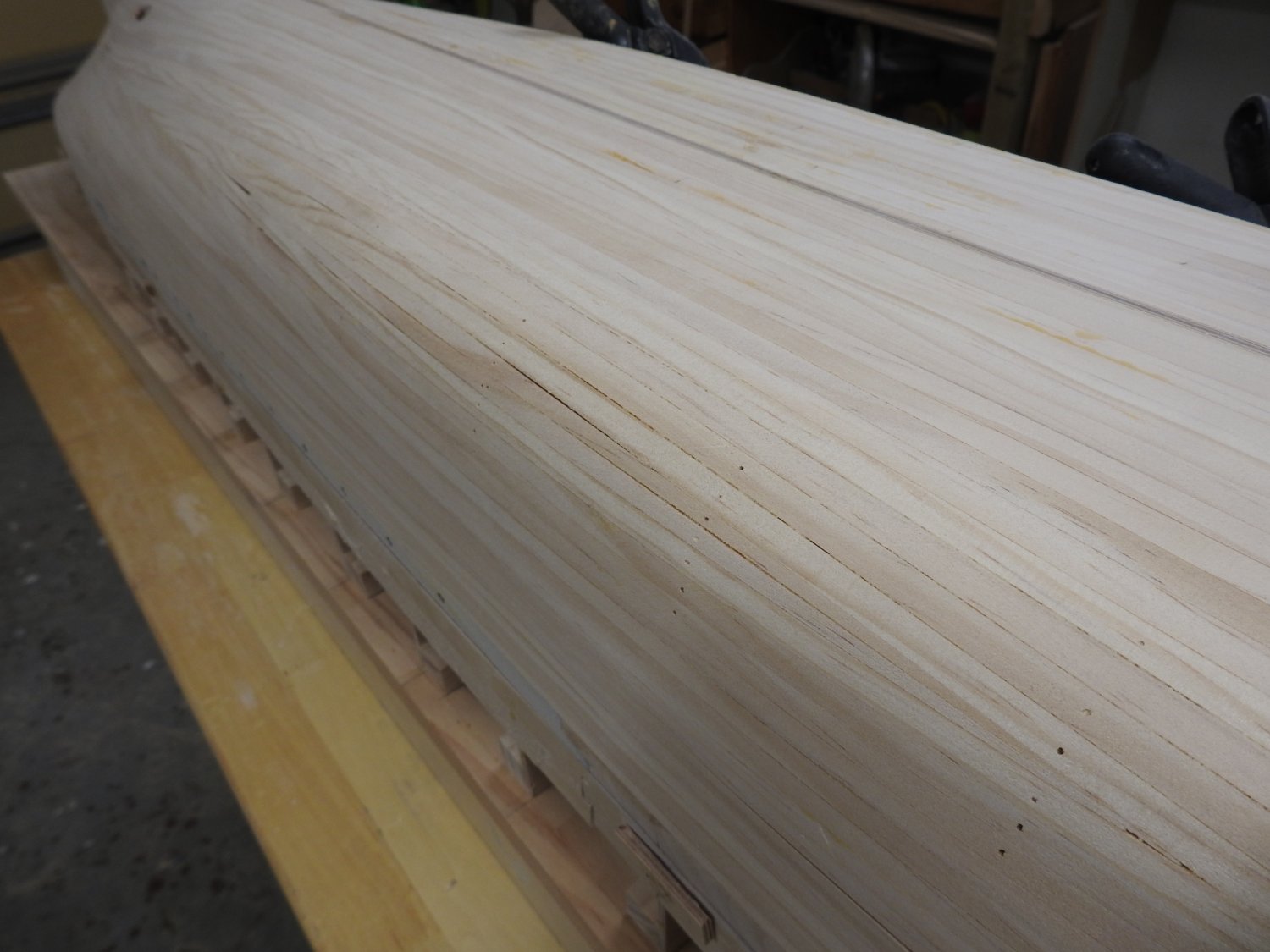
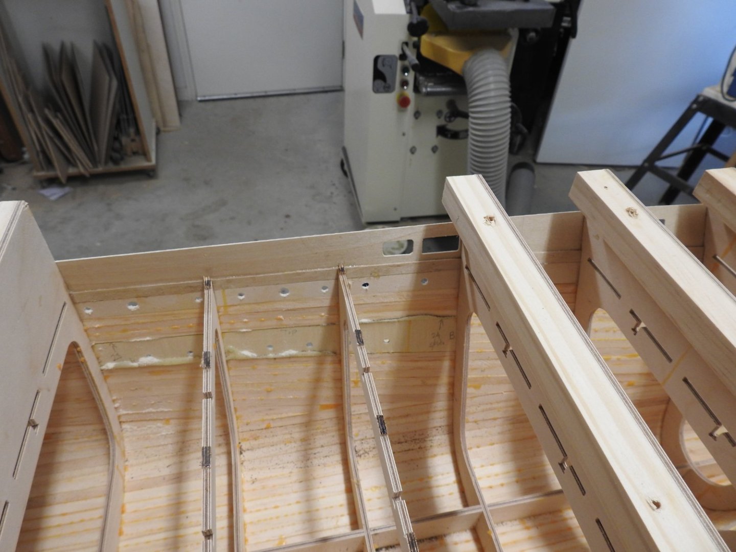
Hull closed in on one side, I have blown out all the dust to show the fit of the planking, no bevelling was done, just nice thin 2 x 8mm strips. The following shows how the 1mm Bulwark is fitted into the gunwale rebate which itself was formed by laminating 2 layers of 1mm ply to form the shelf. the frame extensions act as good firm formers for the bulwark so it stays at the correct flare as the hull is worked on and until its glassed. In the forward most frame there is even some concavity to the form of the Bulwark and it forms to it with some steam. A .5 mm slot was milled into the stem before the keel was assembled to take the stem bar later, it can be seen at forefoot, it looks wider/darker at top of stem due to the bow not being fully shaped there as the feather edge will get damaged if I do it too soon.


-
https://archivesonline.wcc.govt.nz/nodes/view/120383?keywords=ss arawa&highlights=WyJzLnMiLCJhcmF3YSJd https://archivesonline.wcc.govt.nz/nodes/view/120277?keywords=ss arawa&highlights=WyJhcmF3YSIsInNzIl0= Often if there are photos there are plans but the age does concern me, I found Te Anau and Rotomahana in there but also found some of them at the Greenwich museum, sadly these are exorbitant prices, I think i pad $300AU for 4 plans. I have sent an email to my colleague and should hear tomorrow.
-
The archive is mainly for Union Steamship Company ships as the company was based in that city. I can ask though and find out for you. Some of the plan sets have been uploaded now though as we are finishing them off. Here is a link to one of them as an example. https://archivesonline.wcc.govt.nz/nodes/view/787341?keywords=marama&type=all&highlights=eyIwIjoiXCJtYXJhbW4iLCIxIjoibWFwXC9hbWEiLCIyIjoiXHUyMDFjbWFyYW1hXHUyMDFkIiwiMyI6Im1hcmFtYS4iLCI0IjoiXHUyMDFjbWFyYW1heiIsIjYiOiJtYXJhbWEifQ==&lsk=41d072a6db0af6c0f8dcfe3df303f3ce#idx618712 The closest ship to SS Arawa that I know we have is SS Rotomahana which is coming.
-
All that lovely teak decking to lay and caulk with black paper. Six clinker boats to build to.....yay.....

-
Hi Brett I do the cataloguing and sorting for the WCC archive in Wellington NZ and they hold all the plans. Not complete but certainly everything you need including the Shell Expansion.
-
Hi Legion12 The bow and stern are just bread and butter laminations of balsa, not planked as such.
-
I was reluctant to put up a build of this model for two reasons, first I hate having more than 2 models on the go and secondly I was pretty sure the client would not like it. The Client in this case has agreed, provided I do not disclose anything about the cost, time and where it's going to be displayed. As for more than 2 models we don't turn down paid work if we are lucky enough to get it so there we go. I will post images soon but structurally this is almost built, with hull planking approaching the end. This has been 3d modelled from actual builders plans and cut on the CNC from 4mm, 2mm and 1mm ply. Superstructure parts And some later shots of lower superstructure assembled and planking well underway, almost ready for glassing