HOLIDAY DONATION DRIVE - SUPPORT MSW - DO YOUR PART TO KEEP THIS GREAT FORUM GOING! (Only 13 donations so far - C'mon guys!)
×
Richard Dunn
-
Posts
529 -
Joined
-
Last visited
Content Type
Profiles
Forums
Gallery
Events
Everything posted by Richard Dunn
-
 Re the figurehead, I contacted Andy Peters who carved the new figurehead to see if he would se able to scan his work but due to legal reasons and him wanting an NDA to be signed it's become too hard, I have hired one of my work colleagues at the Game studio I work at to sculpt her based off the Linton sketch, if anyone has seen the new K1 trailer you can see the sort of work we do and the characters so the figurehead should be awesome, if you do look its very gory so beware. It can then be resin printed.
 -
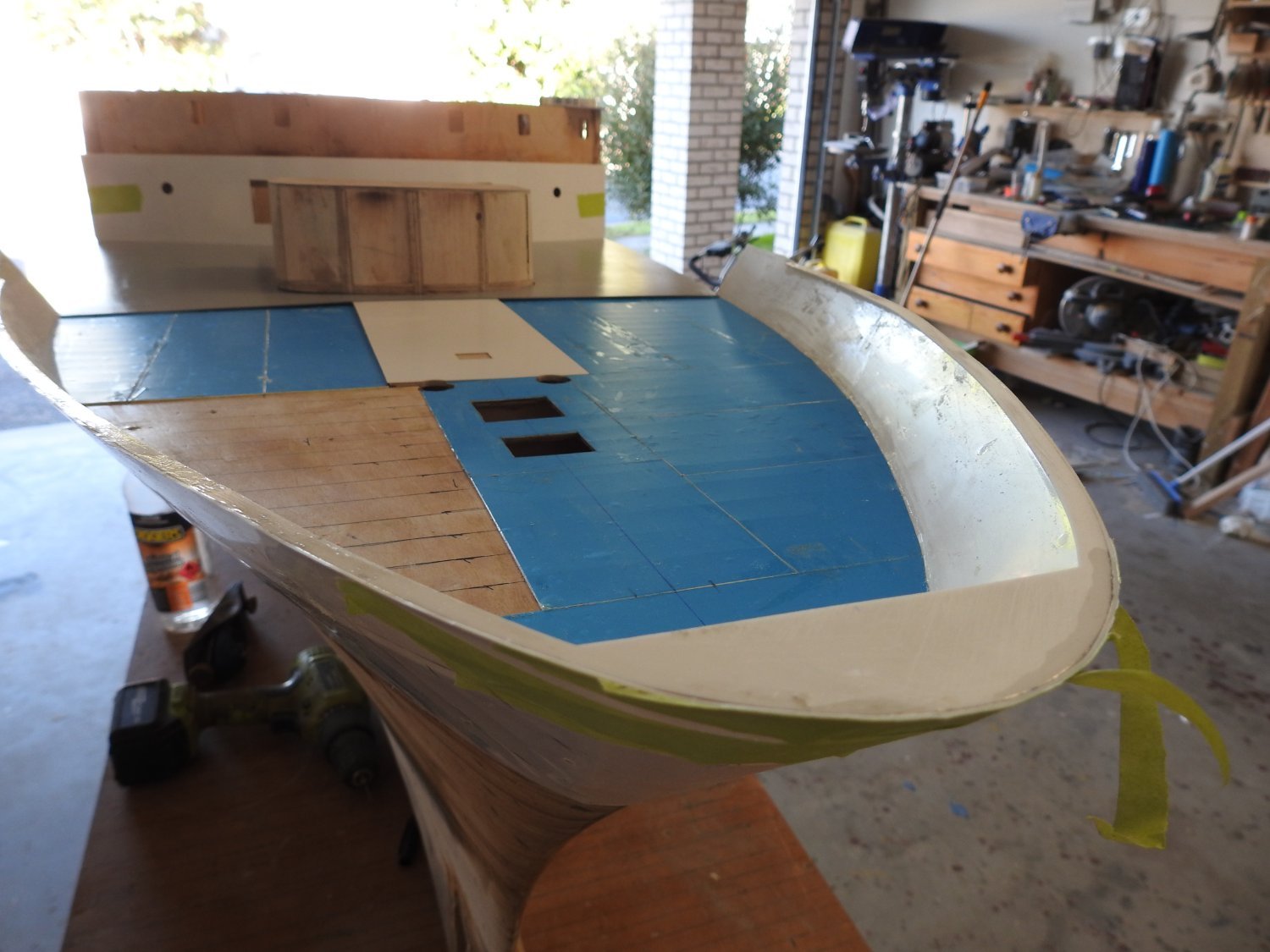
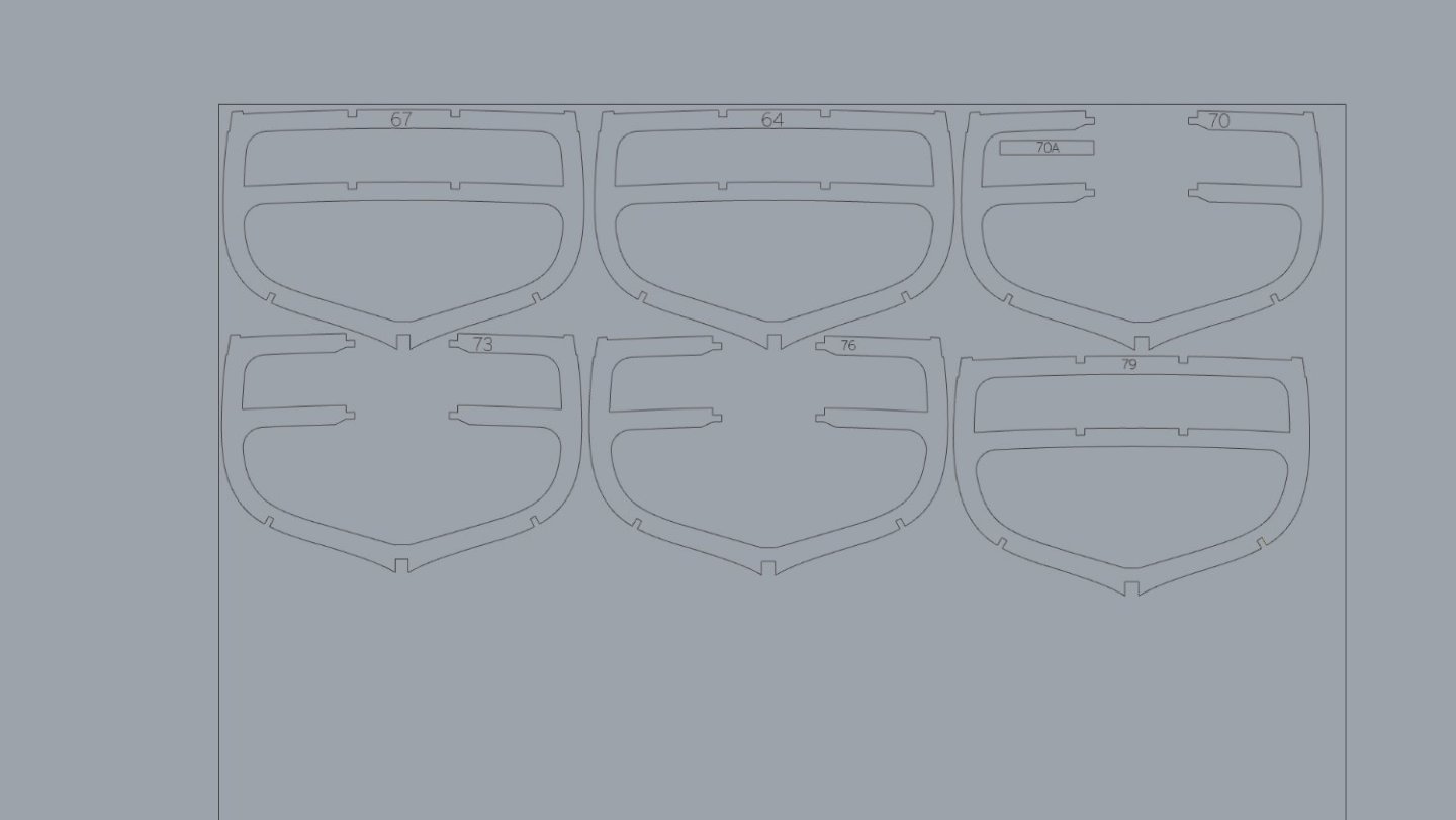
Starting to layout frames for cutting also made allowance for brass lugs for mainstay and Main Topmast stay to be screwed into deck framing for max strength. The shape of the lugs is evident in this photo. Laying out the panelling on the topgallant rail is fun as they are not equal sizes, I realise most would make it even but in reality some panels are 40% longer than the majority, glad I got these measured. 1mm brass lugs can be seen here forward of foremast

-
Well after 8 weeks of 32-38 degrees Celsius no sign of any delamination on unpainted styrene. Will wait a few more weeks while I do this Cutty Sark kit then start on it again.
- 454 replies
-
- 3
-

-
- Union Steamship Company
- Stepcraft 840
- (and 3 more)
-
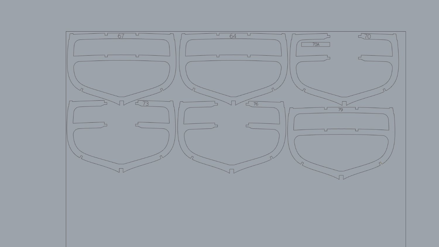
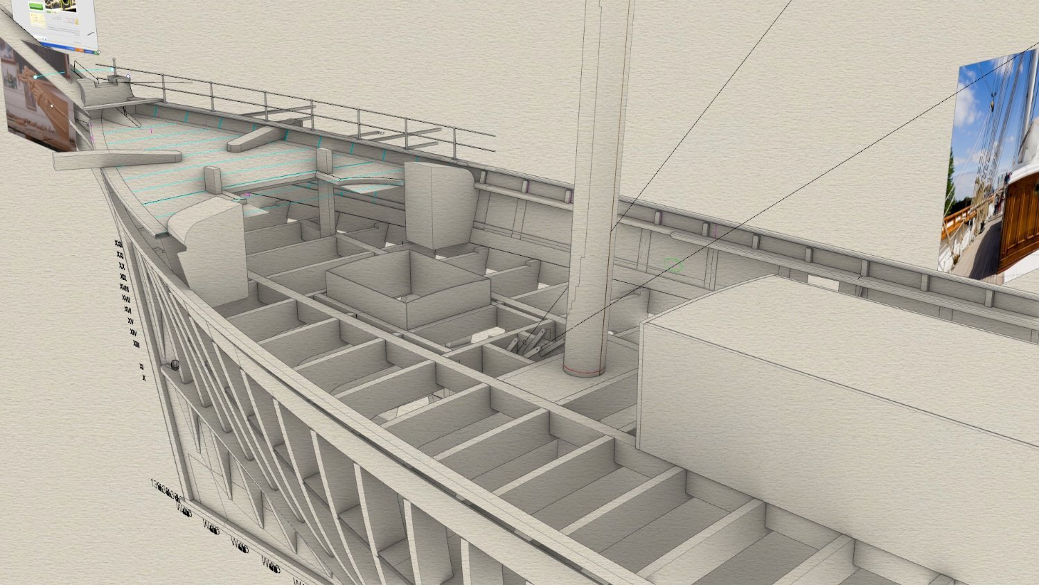
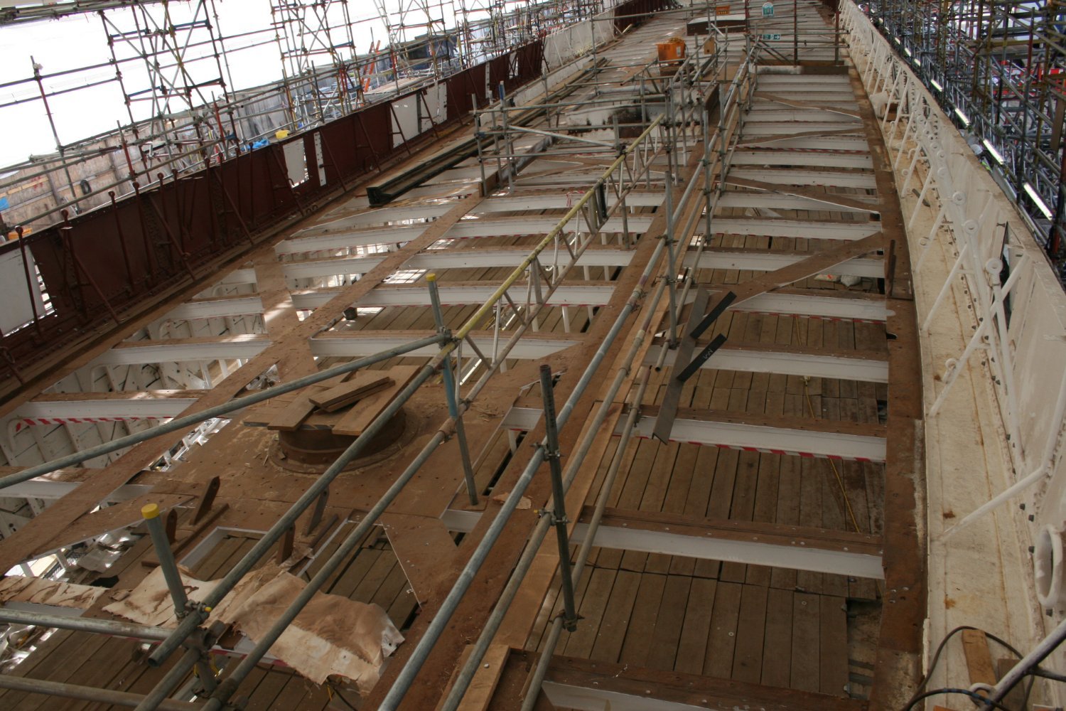
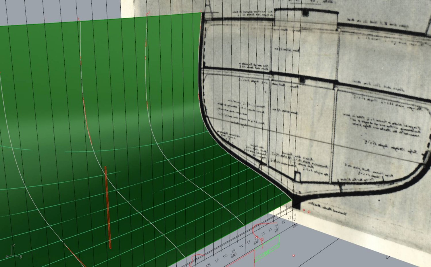
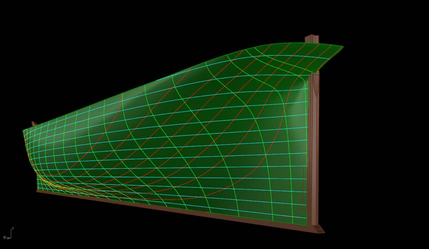
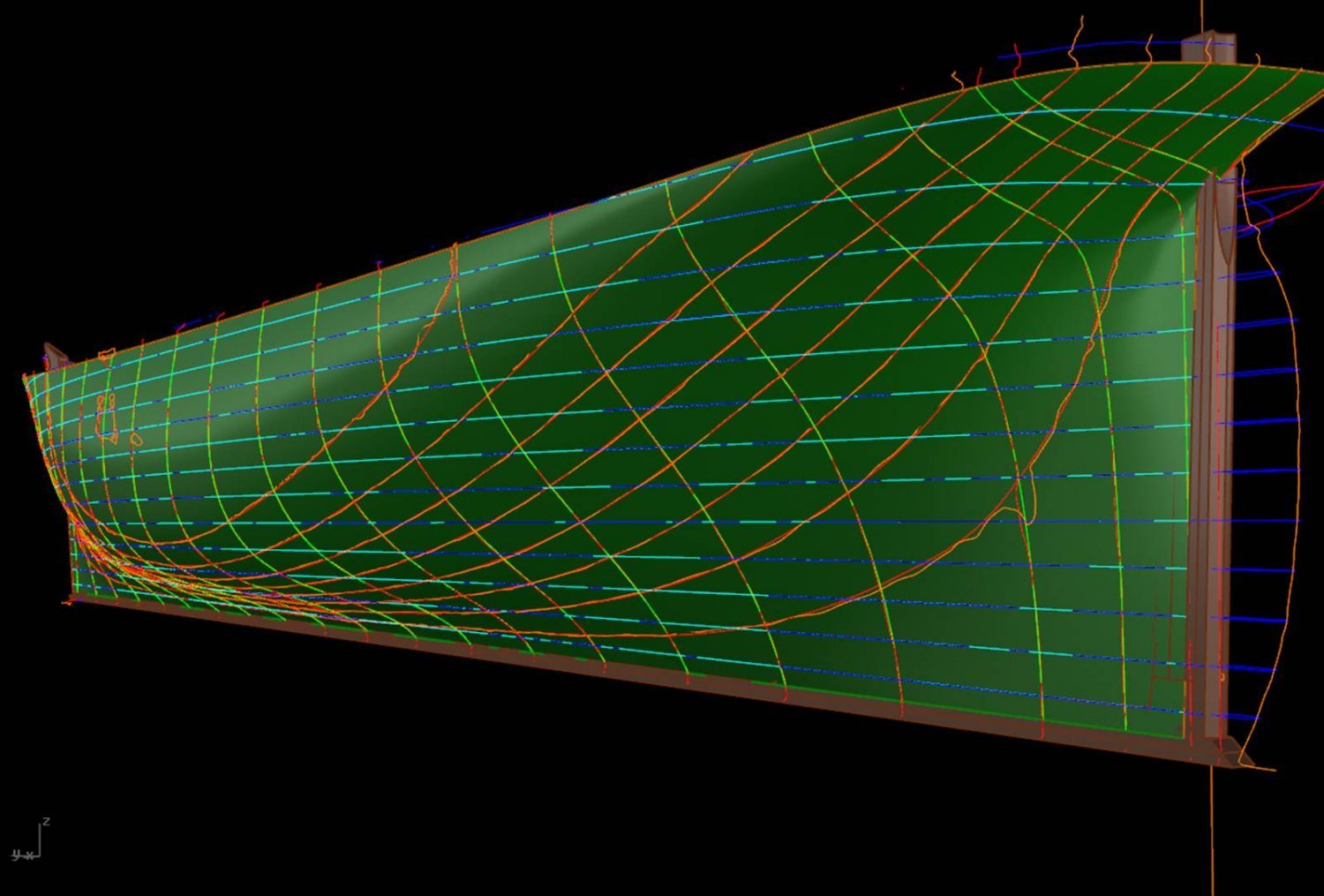
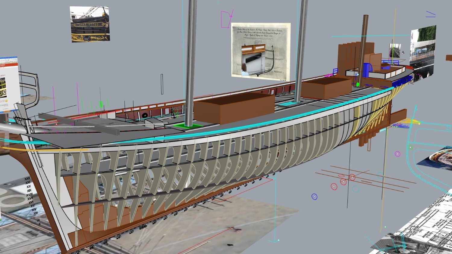
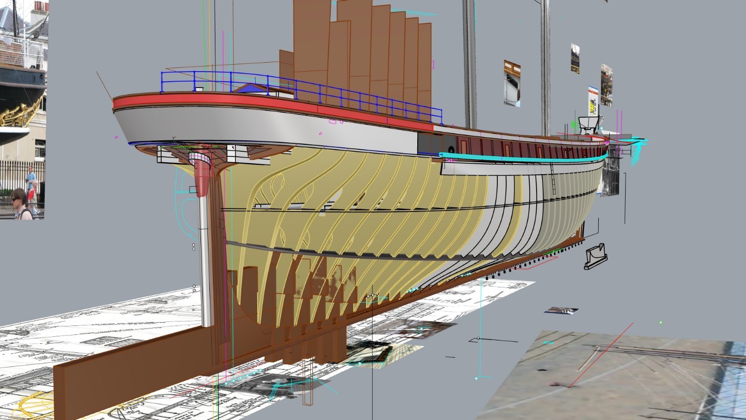
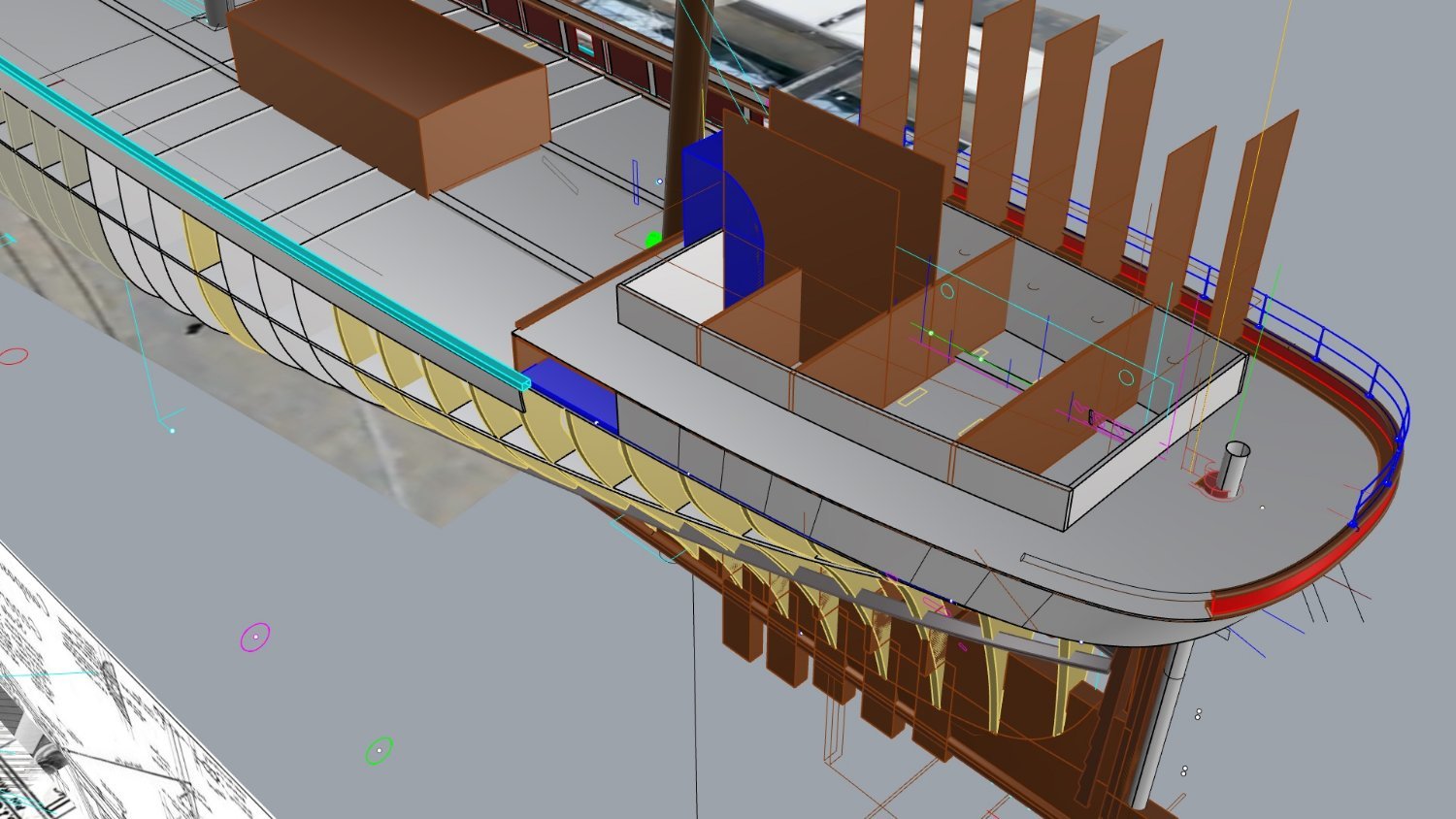
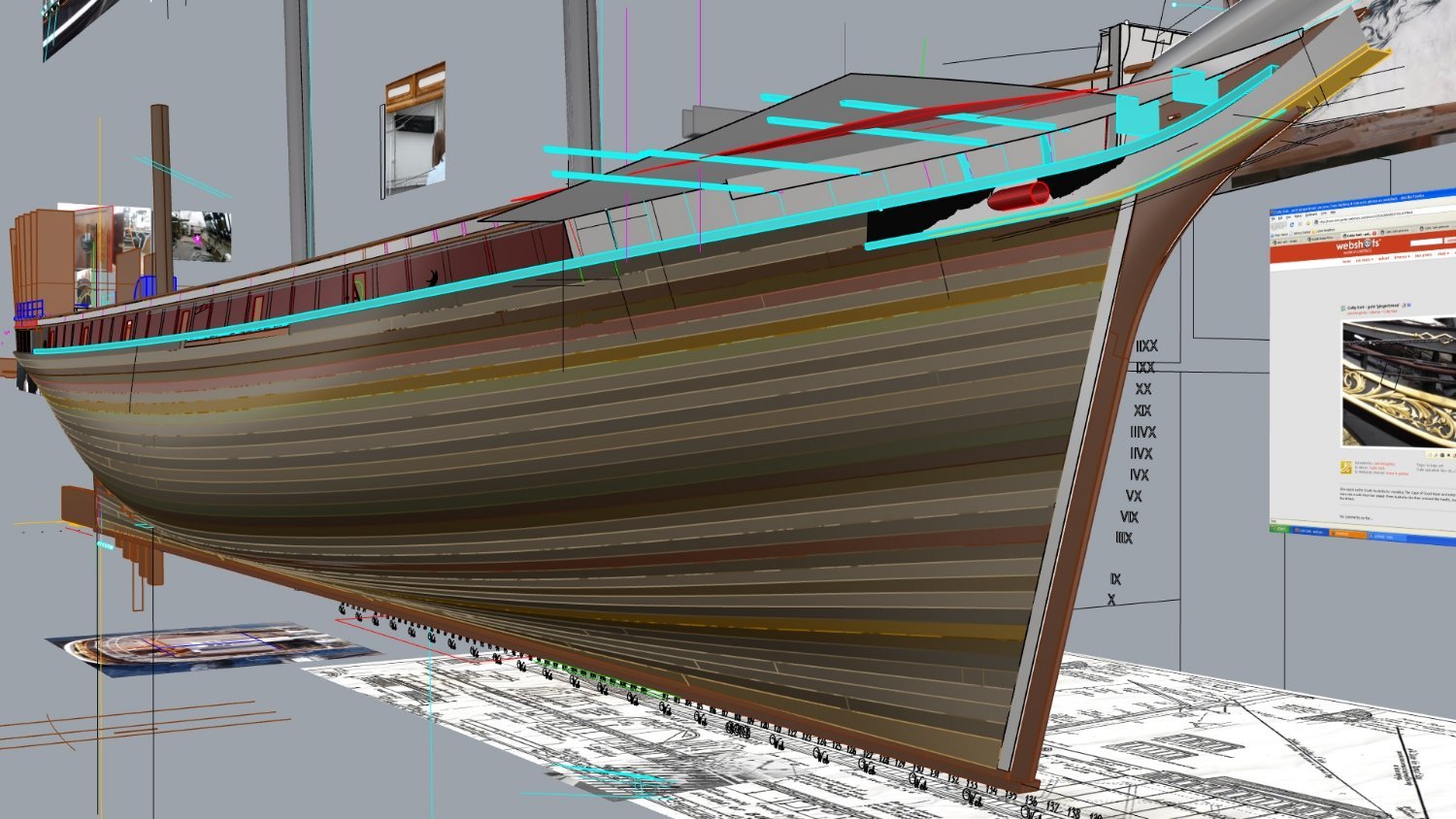
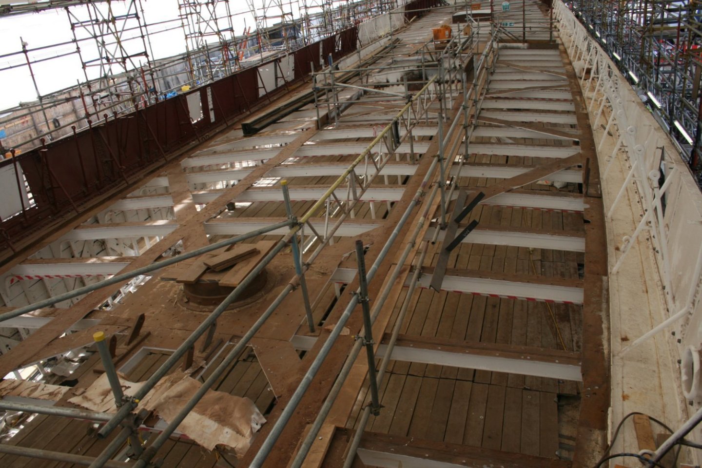
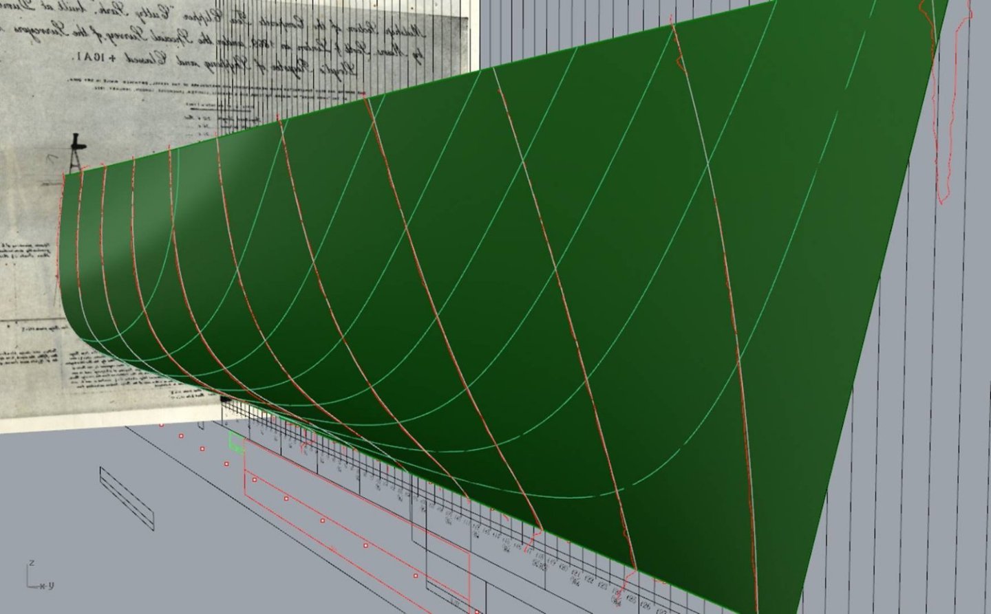
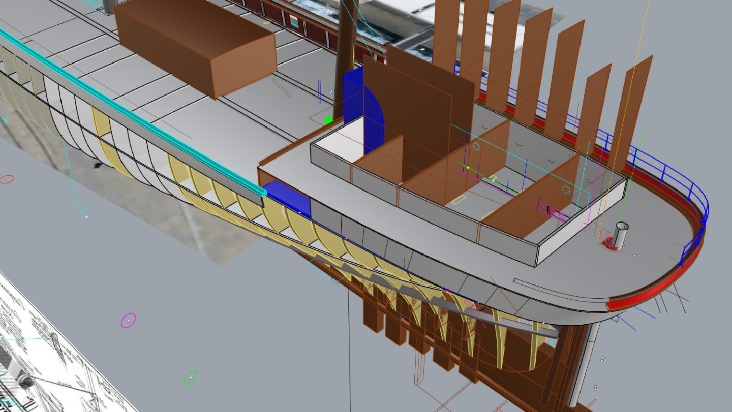
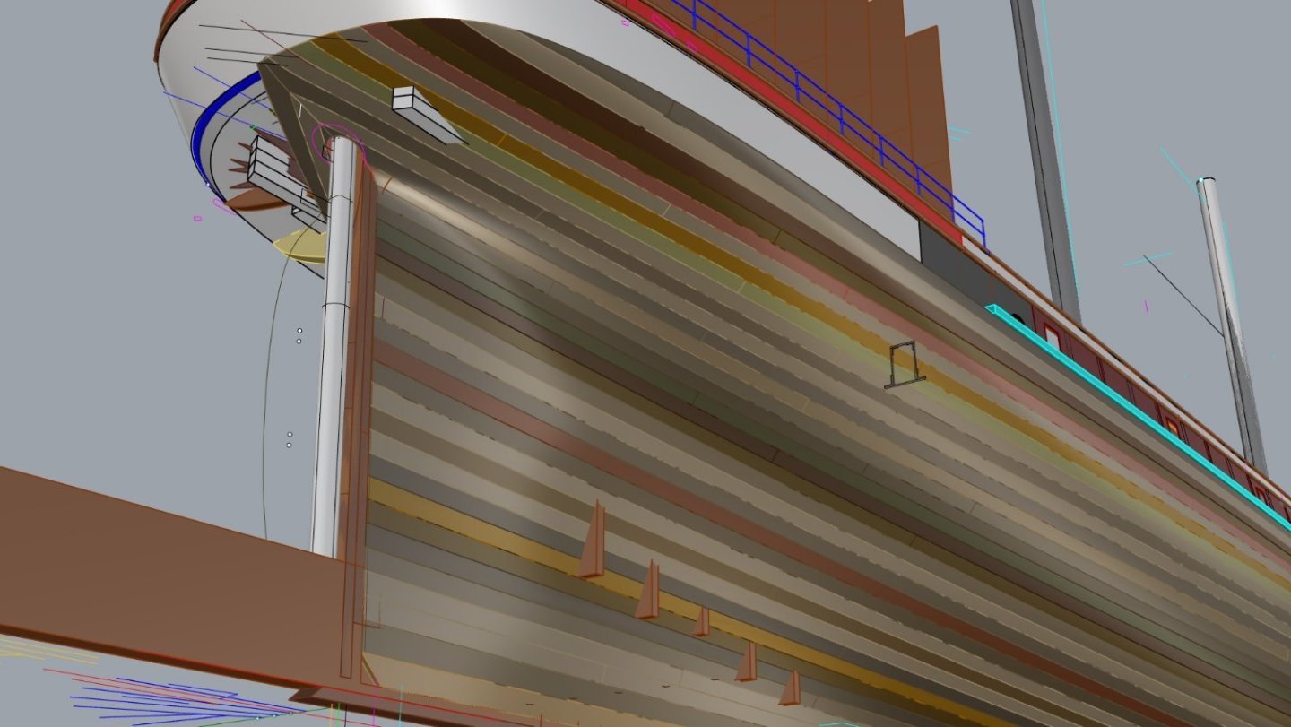
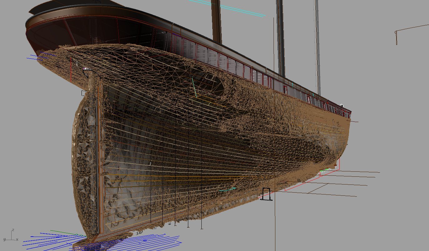
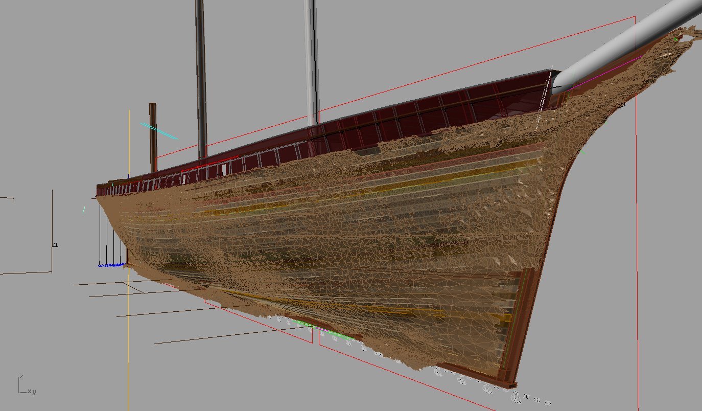
I hope this is in the right section, sorry if its not guys. I am wanting to know if anyone out there is interested in trialling a semi kit I am currently developing for a client. The kit is a 1/40 scale Cutty Sark but unlike all the kits out there this is based on measurements taken during the restoration of the ship which I was involved in recording the structure. The lines are taken from a scan of the hull to exacting precision and the accuracy is carried forward into every part of the model.. For those who don't know what a scan is, its the process of lasers placed around the object in a set grid formation which bounce rays off the surface these points are stored as points in 3d space and are then connected by a surface in CAD software to form the surface, certain surface types respond better than others but the accuracy of the data is precise. Measuring the hull in this manner has not been done before 2011 and as a result plans that exist have all derived from calculated guessing and visual study of the shape, old preliminary midship plans (Rennie) which were not built to and sometimes based on similar ships, all that is fine if the data is not available ,which is was not so some did a good job of getting the form Below can be seen the resulting mesh overlaid over the model, it was used to deign her current display system suspending her above the dock,. I should mention I have compared all available plans of her against this scan and not a single one is correct, some are better than others but all have failed in one area, the sheerline, some are too flat aft, some re too flat forward, some have the rise of floor totally wrong but as you can see we have this info now, these are significant errors to 2-3 ft in full size which is amazing to me. I should point out as well that the sagging of her hull structure and dropping of her bilge as a result has been allowed for as it was not over the whole surface but only in certain areas that were not shored up. Anyway these images will show how close the model is to the laser scanned surface now. I should add I am also able to provide a lines plan now if anyone just wants the proper lines for a model and take it from there. It has been in research for 10 years and it's taken me some time to find the time to do this. The kit will consist of all the wood and plywood parts needed to build the hull and planking of hull and decks including the panel work of the deckhouses, it is based on the woodget era while she was in the wool trade. I was drawing this up in 2010-2012 from measurements of her structure while she was just an iron skeleton, this enabled the unseen parts of the ship to be measured like never before, although a lot of this is not relevant to model like the deadwoods etc it did make it possible to get every detail correct. I do not expect the interest in this to be large, if any at all, as many kits exist already albeit out of scale and incorrect but if that's ok with you then great but I like to do things right as a record of history. The hull is framed using the actual ships web frame positions and the planking is to scale and correct as per ship with even the butt positions the same as the original. I will go into more detail later and expect to be cutting the first set in the next few days from .4, 1mm, 2mm, 4mm birch high quality plywood, the 4mm ply is 8ply, and very stable. The backbone and pre-shaped planking is Cherry and Anigre for decking. The bulwark plates I will cut from brass, at least at this stage I plan to. Below are some images of the 3d model of the kit showing some of the structure. Hull length is about 1600mm and 280mm beam. the beam is the biggest limitation if yards set square but at this scale it can still be displayed in a house with 8ft roof I am doing this for a client for a personal model but if anyone is interested in an accurate model let me know. An example of the details and what was measured without structure in the way, here is the top of the stempost under the bowsprit, hundreds of these were taken and drawn into plans If you have any questions please PM me, I can do trials after I assemble a version myself and fix any fit issues and could do it for cost of materials only, weight should be low, less than 6kg Lines from scan of hull, the orange lines are the scan sections compared to the faired red sections used C Jordan got the midship pretty spot on in 1922 Planking Framing Interior of coach house being built for what's seen through skylight.


-
Just an update, we have had a heatwave over here in Australia, so it's been about 35 degrees Celsius, I decided to wait and see what happens to the plating in that heat for a few weeks. So far no issue at all. In the meantime I have been building a nice fancy new big workbench. I also need to find a rope walk.
- 454 replies
-
- 2
-
-
- Union Steamship Company
- Stepcraft 840
- (and 3 more)
-
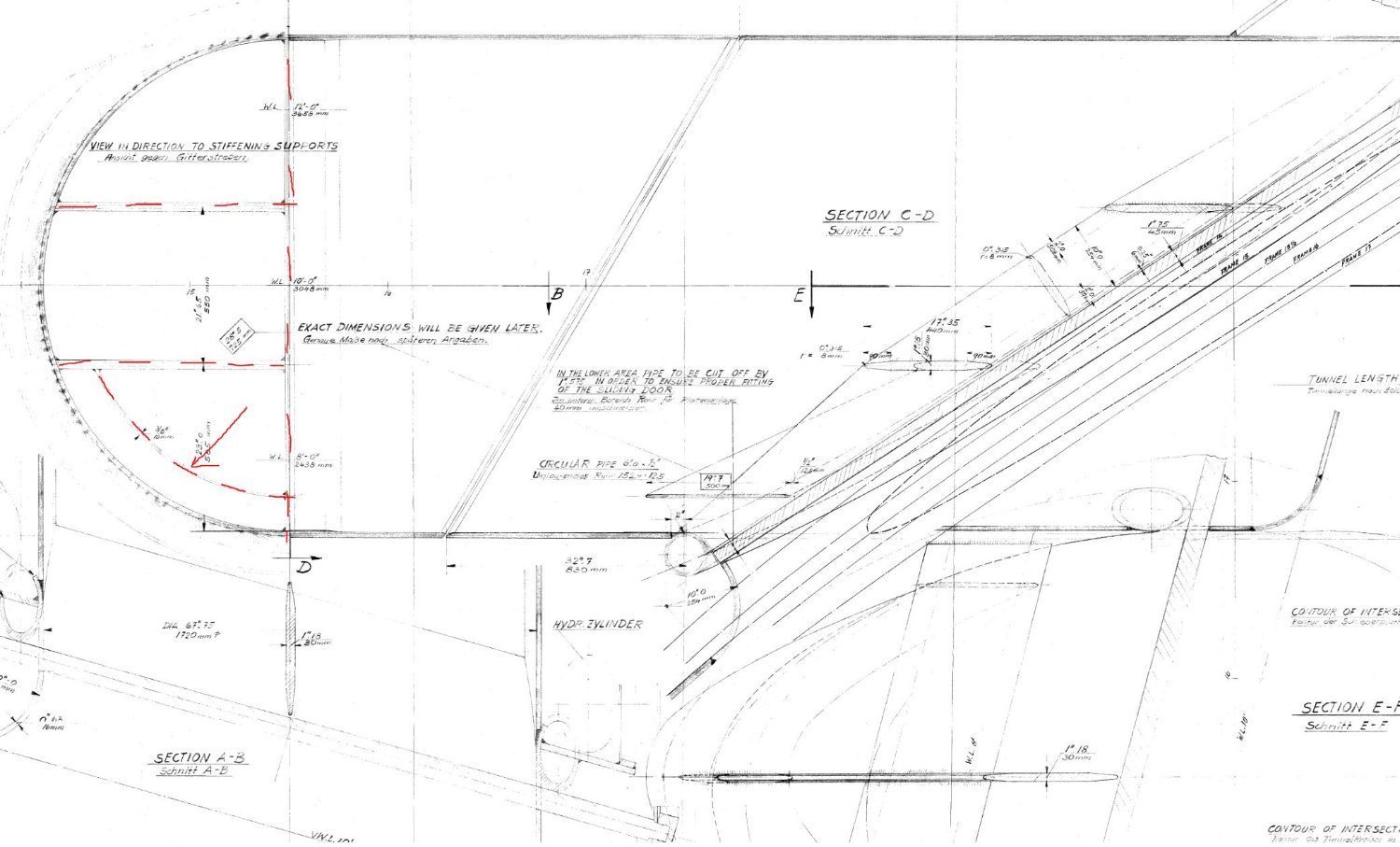
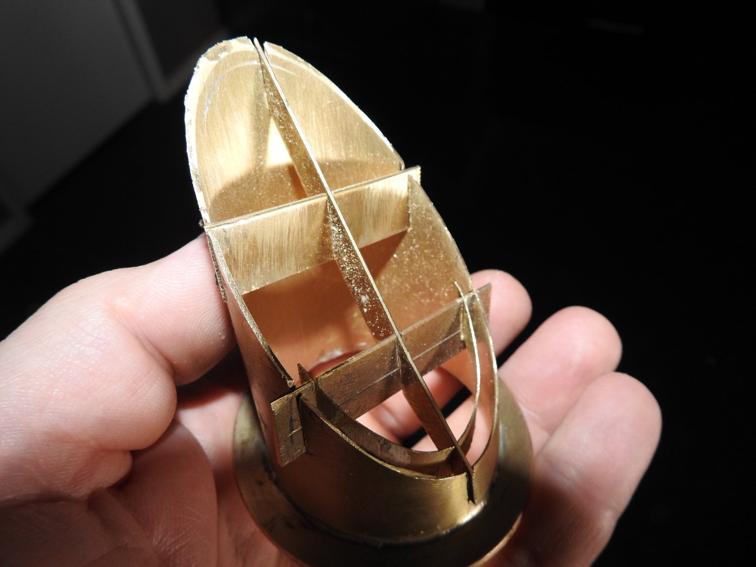
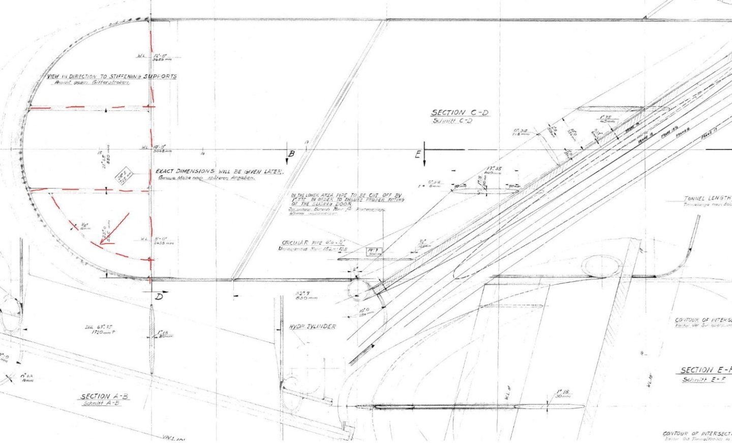
Just an update. Propeller shafts are installed and bossing's ready to plate. Rudders are made and installed ready to plate and install servo. Bow rudder is finished ready to plate. One A bracket it made and fitted. Lateral thrusters are installed and the belmouth gratings are being made now, a very tricky job as they are not straight gratings.... of course. Plating is still proceeding well on lower hull Here is part of a plan showing the aft lateral thruster tunnel grate and the model one ready for soldering. the part being indicated by the arrow was a real sod, its done with half checked slots and made from 1mm and ,3mm brass. The slots are just done with a fine Dremel grinding blade.

- 454 replies
-
- 8
-
-

-
- Union Steamship Company
- Stepcraft 840
- (and 3 more)
-
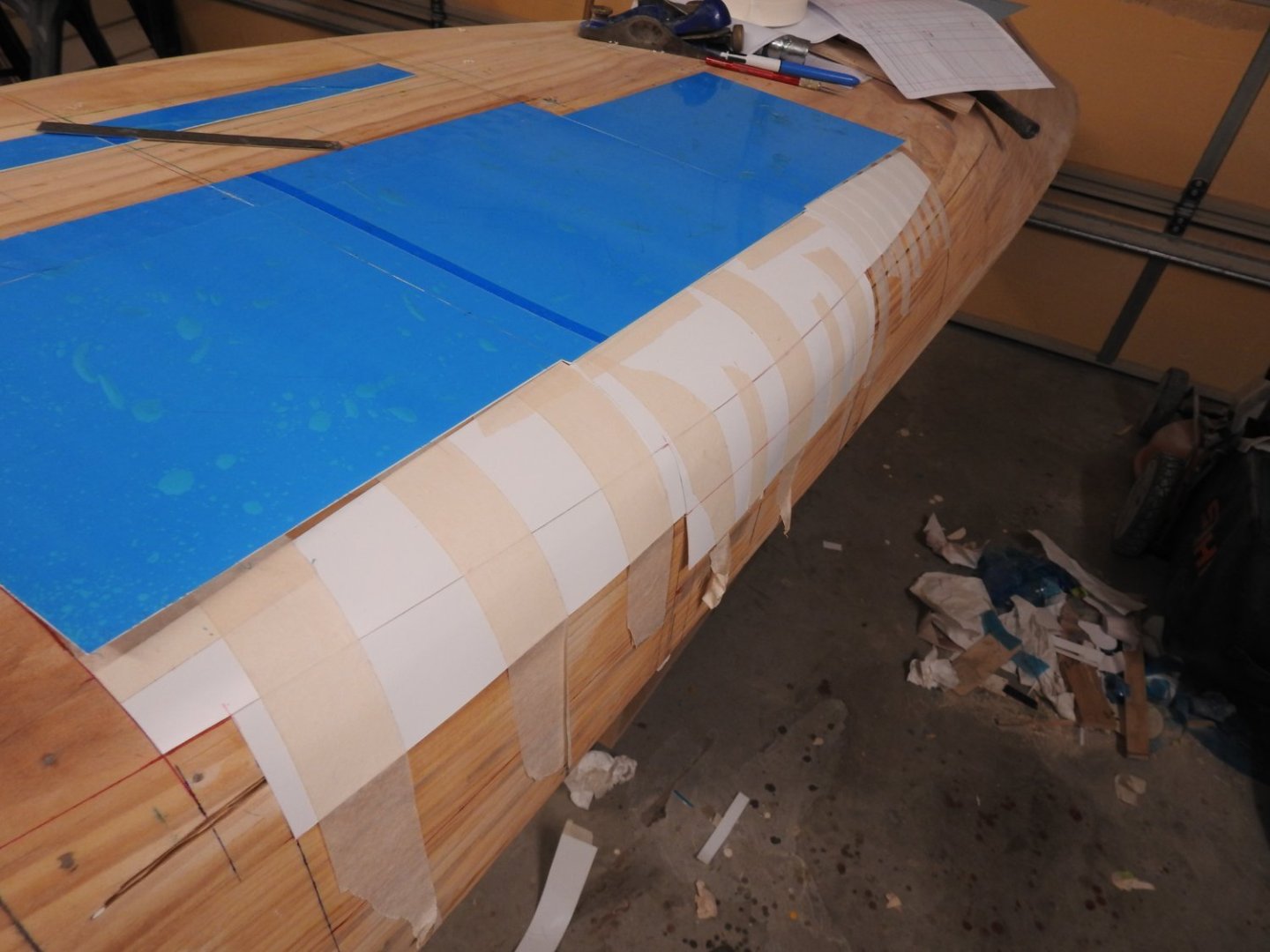
I have stumbled on a really good technique for shaping plates when you don't want to or can't vacuum form. First what did not work Heating the plates in boiling water on a portable stove next to model so plate was on and formed within 2 seconds of leaving the water. The plastic still sets too quickly. Taping down and heating with heat-gun, it heats unevenly and bubbles and curls. What did work as can be seen below in the white bilge plates. Cut the plate double oversize and tape it firmly to the hull on the bottom and fix a heavy counter weight to the bottom hanging edge, I used a metal pipe and tied in on with string through holes in the sheet as tape will let go once heat is applied. moving the heat-gun really quickly gradually heat the plate in lines and as it starts to soften it stretch's the plate rather than buckle it. then trim it up It works! No bubbles or weirdness, in my case these plates are the only ones that require forming on the hull
- 454 replies
-
- 7
-
-
-
- Union Steamship Company
- Stepcraft 840
- (and 3 more)
-
Exactly, thats why I initially thought I just need a switch, but having to reverse the motor means I need a speed controller even though I don't need the speed side of things, but being able to power up the thruster instead of just engaging it suddenly is easier on the bevel gears. If the motor just turns on full tilt it places stress on the poor little buggers.
- 454 replies
-
- 7
-
-
-
- Union Steamship Company
- Stepcraft 840
- (and 3 more)
-
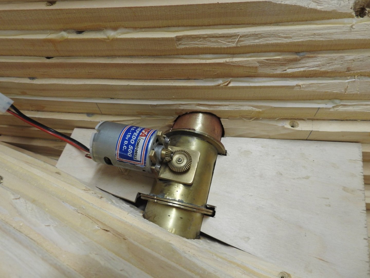
I had without thinking just thought an on off and that's it, no other functions but of course it needs reverse to, so I think I am going to need a speed controller after all fora 12v motor. MFA Torpedo 500 Motor Reference: MFA/0/4/500 Condition: New product MFA Torpedo 500 Motor 6v-12v Dia: 35.7mm Length 50mm Weight: 146gm 13,350 RPM at 12V Includes: bracket, harness and suppressed. *Generally used in medium sized models for many functions Sadly I have zero understanding of electronics so getting all the right gear is a challenge. I do have all the gear for the main motors though. The thruster motors are these so need a speed controller for these and I have a dedicated servo for each thruster already purchased
- 454 replies
-
- 1
-
-
- Union Steamship Company
- Stepcraft 840
- (and 3 more)
-
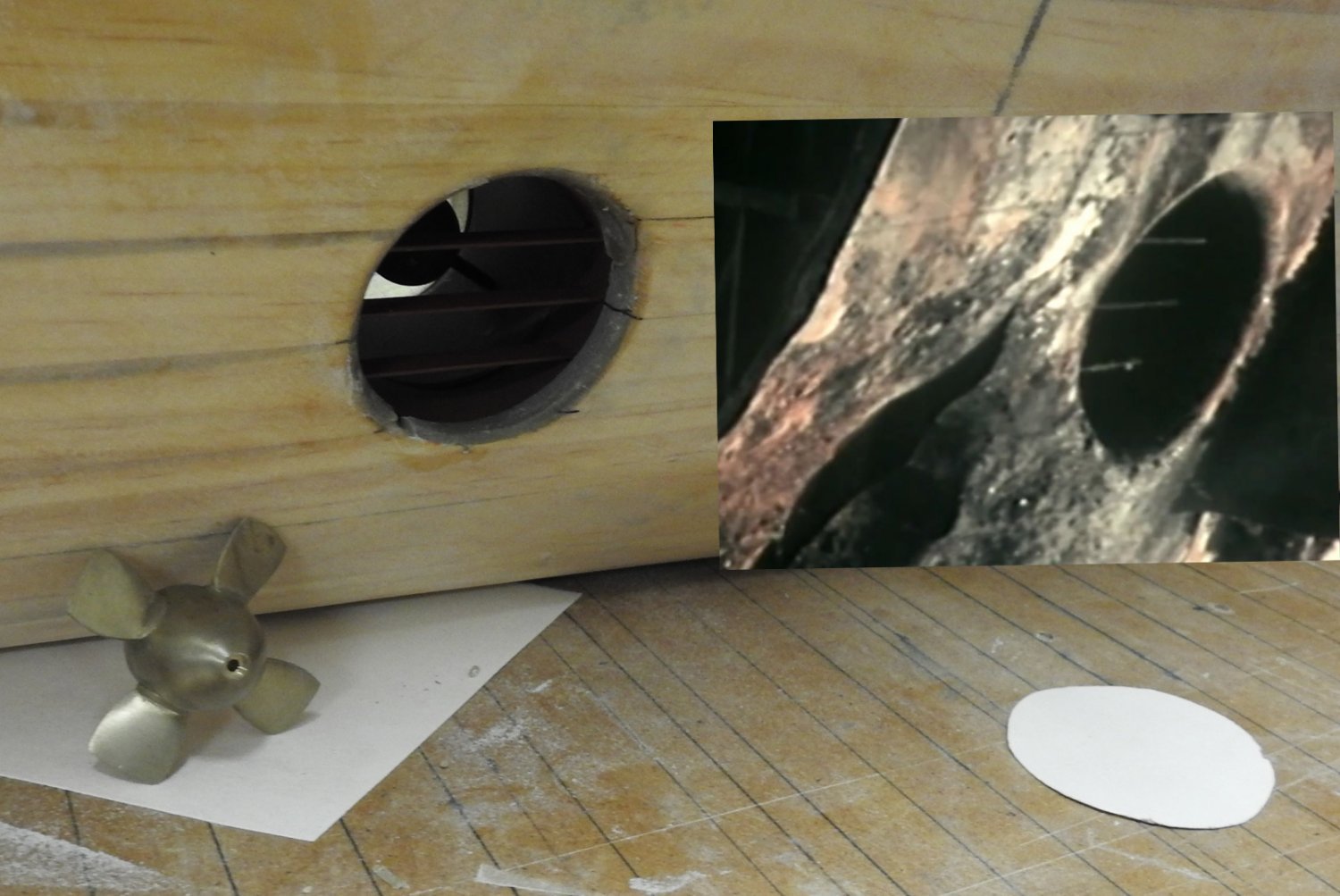
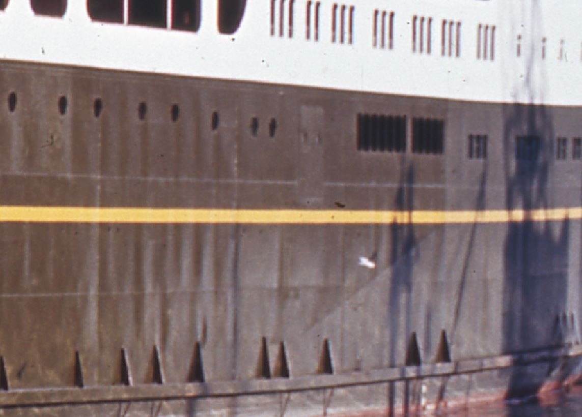
One side painted and installed. Model and actual from wreck

- 454 replies
-
- 5
-
-
- Union Steamship Company
- Stepcraft 840
- (and 3 more)
-
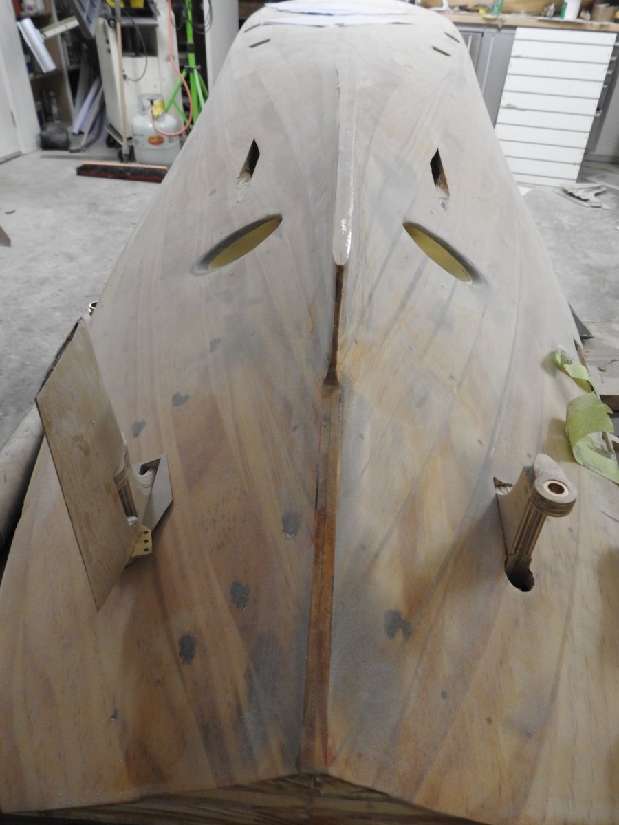
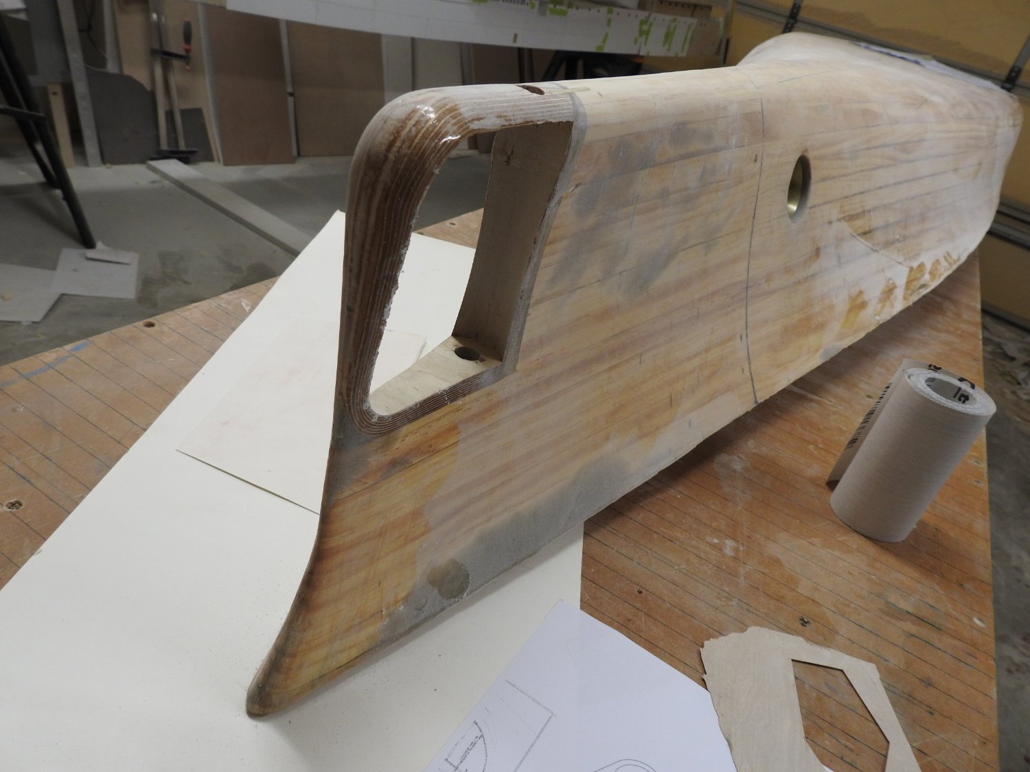
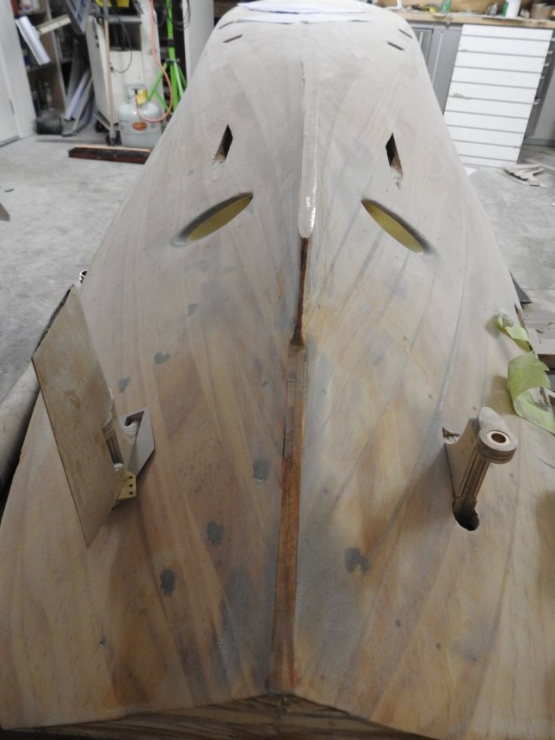
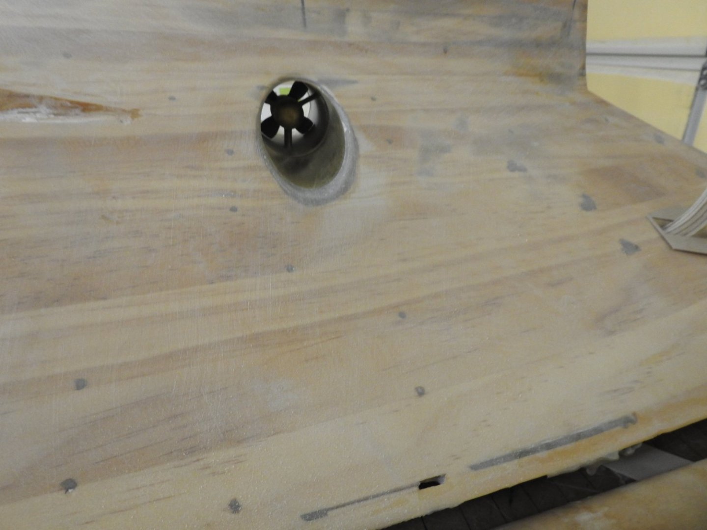
I need some help guys What's the best way to simply have an on off switch for a motor using a servo to control it, basically I just want to make the electronics to turn off and on the lateral thrusters, no speed control is needed just off and on. I would assume a contact point that can be depressed with the arm of the servo which in turn is controlled by a servo trigger board to control the arm on the servo's range. Some updates to the running gear installation. Hull has been glassed and sanded. Lateral thrusters installed and bell mouths shaped the tunnel has to come out and have the grill soldered into the brass part and painted then it can go back in and the hull plating proceed. Bow Thruster The aft portion of this still has to have the fairing scoop shaped out of the hull as can be seen here The aft tunnel The rudder horn being fitted and the Bow rudder frame is shaped, so is the rudder but not shown here, the tapered cylinder above is the bossing for one of the prop shafts

- 454 replies
-
- 6
-
-
-
- Union Steamship Company
- Stepcraft 840
- (and 3 more)
-
That invitation goes for anybody that happens to be in Logan Reserve in Brisbane, feel free to let me know if you want to look at the model.
- 454 replies
-
- 1
-
-
- Union Steamship Company
- Stepcraft 840
- (and 3 more)
-
Thank you Yeah it does look overdone in the shot, partly because of the high gloss on some of the plates and also due to the zoom on the camera but its still got to be sanded a bit and primed. I will be starting to plate the bottom part of the hull soon, as soon as I finish the bow rudder I can go to aft end of bilge keels. and will prime that in red oxide before going further aft as their is still bit to do down that end . I still have the rudders to make and fit, the prop bossing's to make, just waiting on a plan from archives I need replaced and the stern lateral thruster to fit. The joint around the hull has been fitted so I can butt the plates to a nice crisp angle and will start with the top strake of plates, its actually really not as hard as I thought, 90% of the plates are not requiring heating to conform to the compound shapes, the hull is such that most conform as is, only the ones on the midship bilge area will need to be heat formed. The many openings in the hull will be done after priming, and soooo many to do above and below WL, some are 12mm diameter, some are just 2mm but about 100 all up I suspect. I am in the process of trying to get some resin waterslide decals made for the rivets, plimsol and depth number from Railtec in the UK as they do custom stuff, but have grave concerns about this as just not hearing from them. I will update on this if I hear something as they seem to do a good job, but I suspect I am in for a too long of a wait and looking at other options as communication is just not happening.. had 3 props made by prop shop in UK in half the time I have been waiting for even a quote If anyone knows another source please let me know, and they do need to be custom, Archer do not make anything suitable
- 454 replies
-
- 1
-
-
- Union Steamship Company
- Stepcraft 840
- (and 3 more)
-
No it's managable. If you are ever up this way, call in Jim.
- 454 replies
-
- 1
-
-
- Union Steamship Company
- Stepcraft 840
- (and 3 more)
-
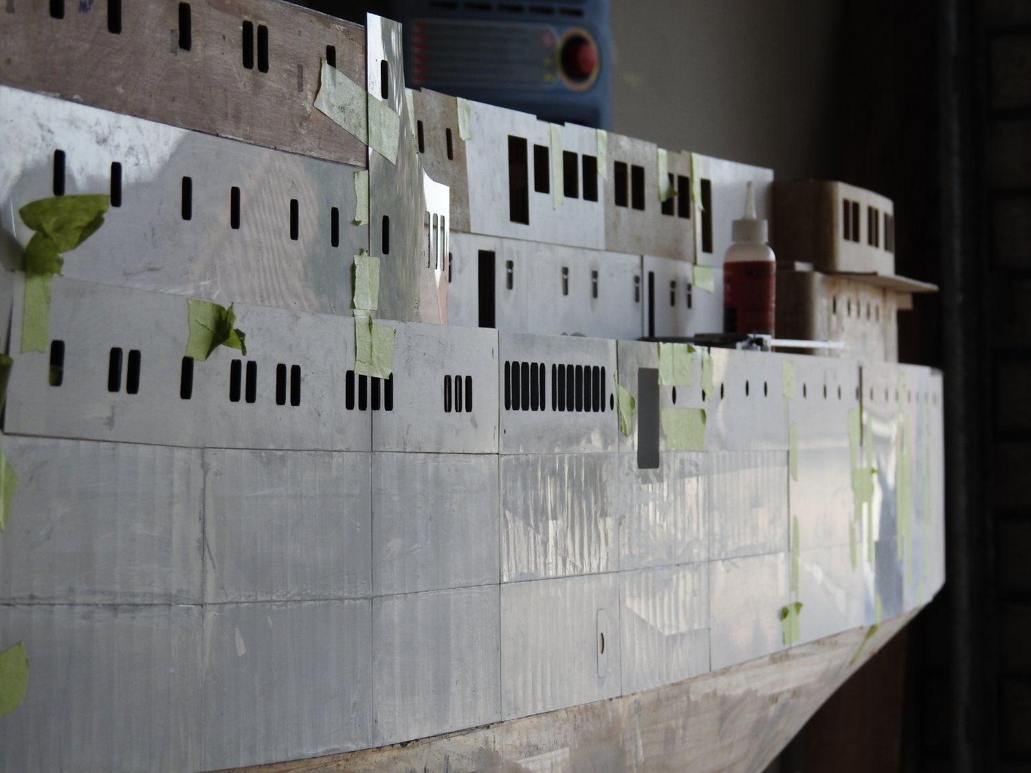
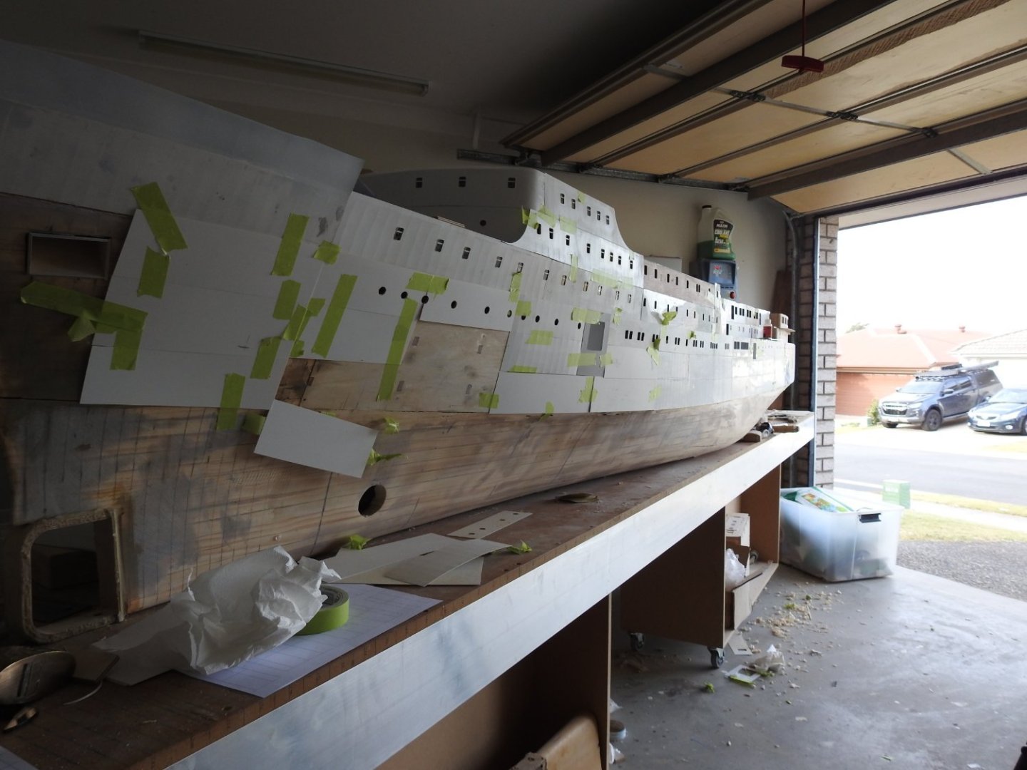
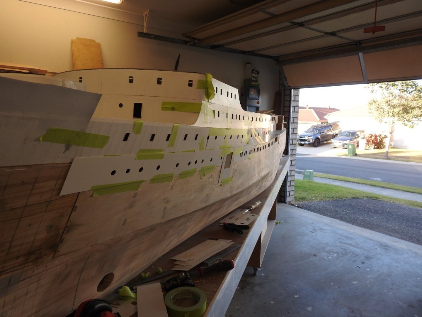
I took a shot with extreme backlight from outside as the sun was going down which shows the tin canning off in high detail, its not this pronounced normally (like above shot) but you can see the plates, deck boundaries and tripping brackets on web frames Note the actual photo taken from other direction but how the ramp is visible through the plates as is all structure The small gaps for the.5mm rod weld seams can be seen between plates, also how some plates are thicker than others and stand out, as per the plating plan. once the surface is an even patina and primed it will look a lot neater but you get the idea hopefully.

- 454 replies
-
- 9
-
-
-
- Union Steamship Company
- Stepcraft 840
- (and 3 more)
-
Thanks guys. I hope to have a few plates on hull this weekend, not window ones so quick to do.
- 454 replies
-
- 3
-
-
- Union Steamship Company
- Stepcraft 840
- (and 3 more)
-
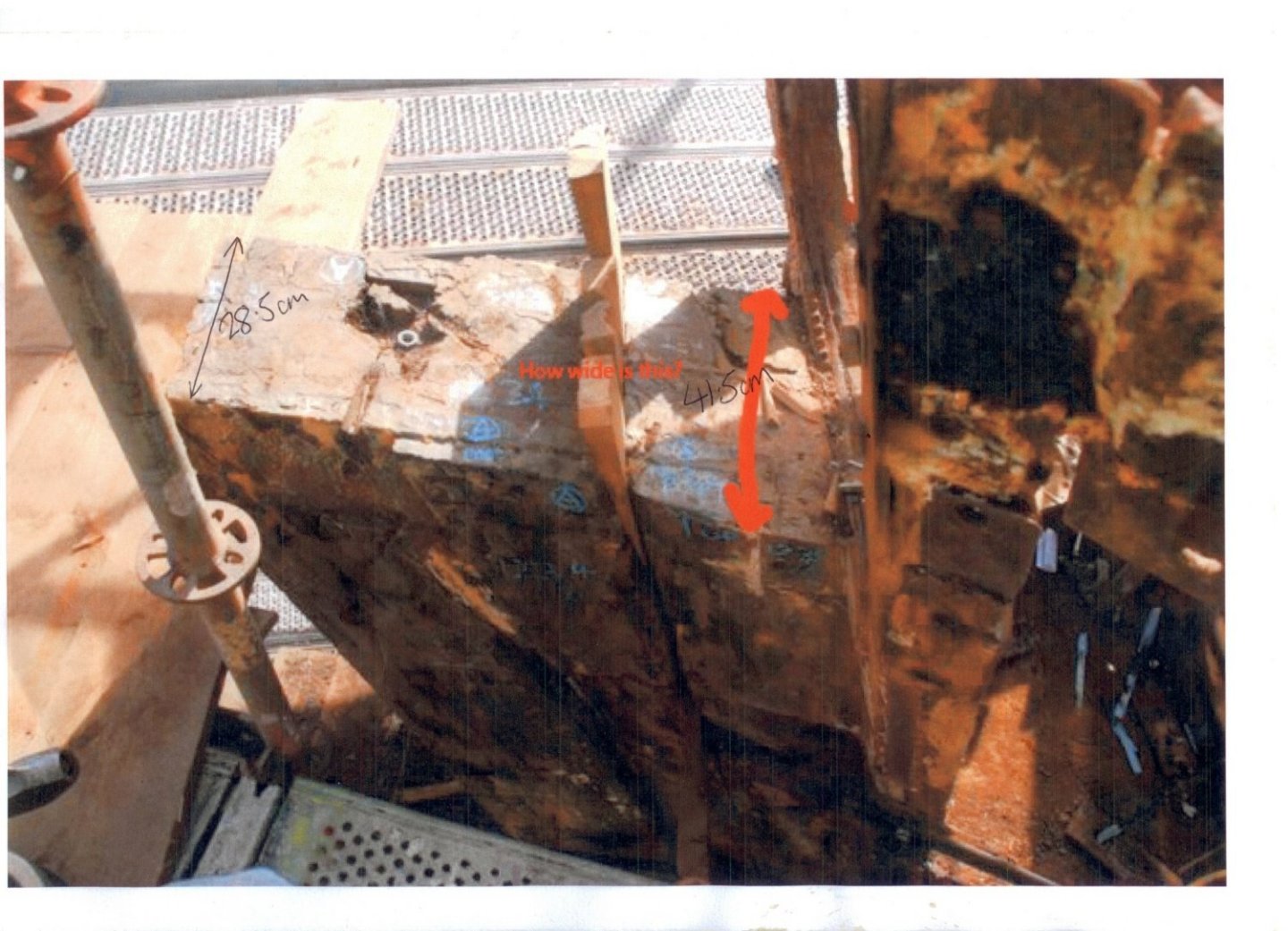
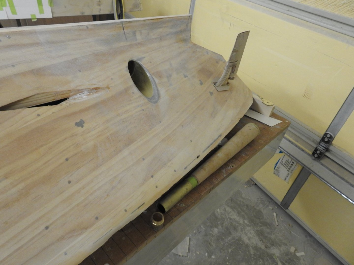
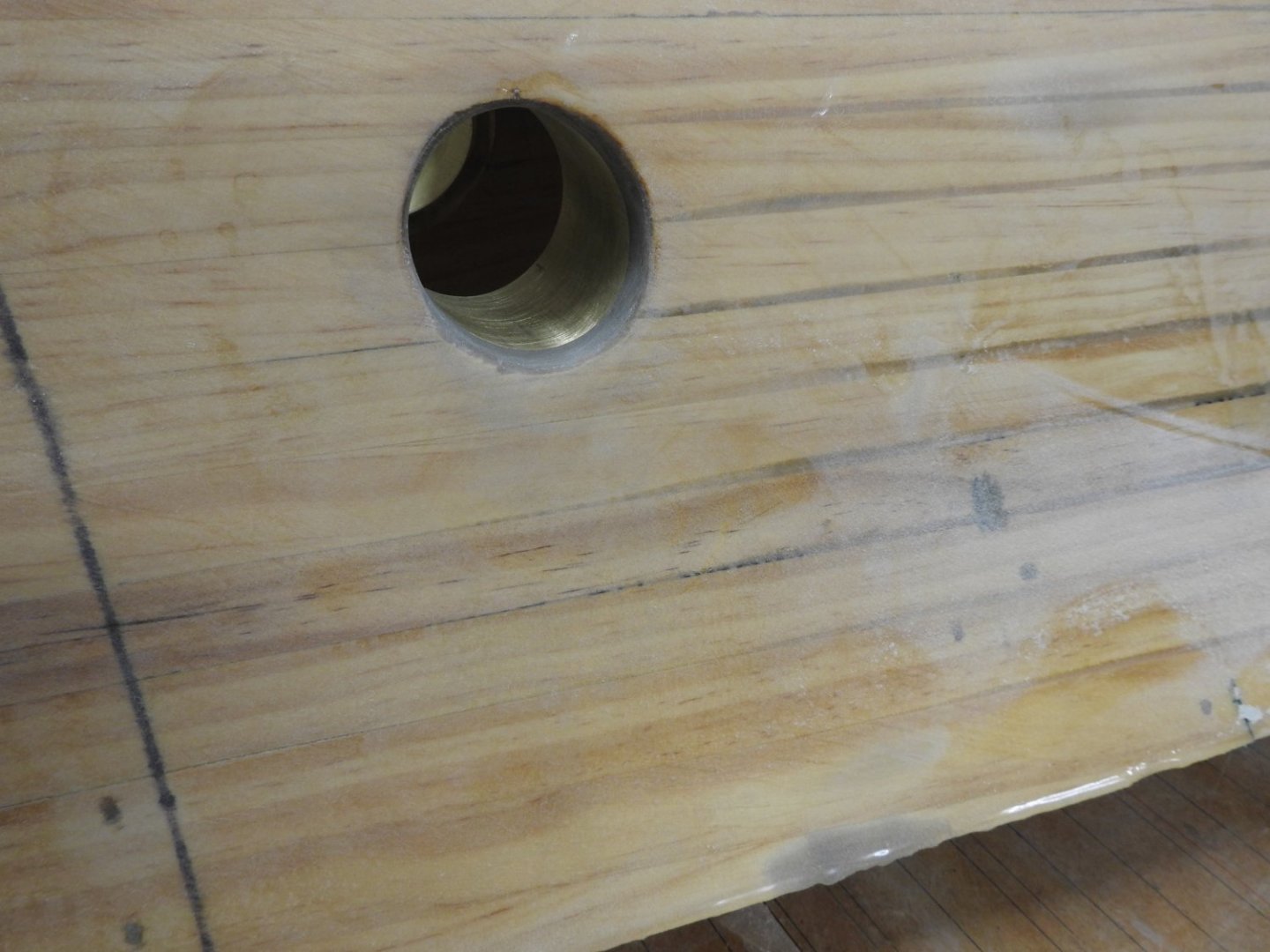
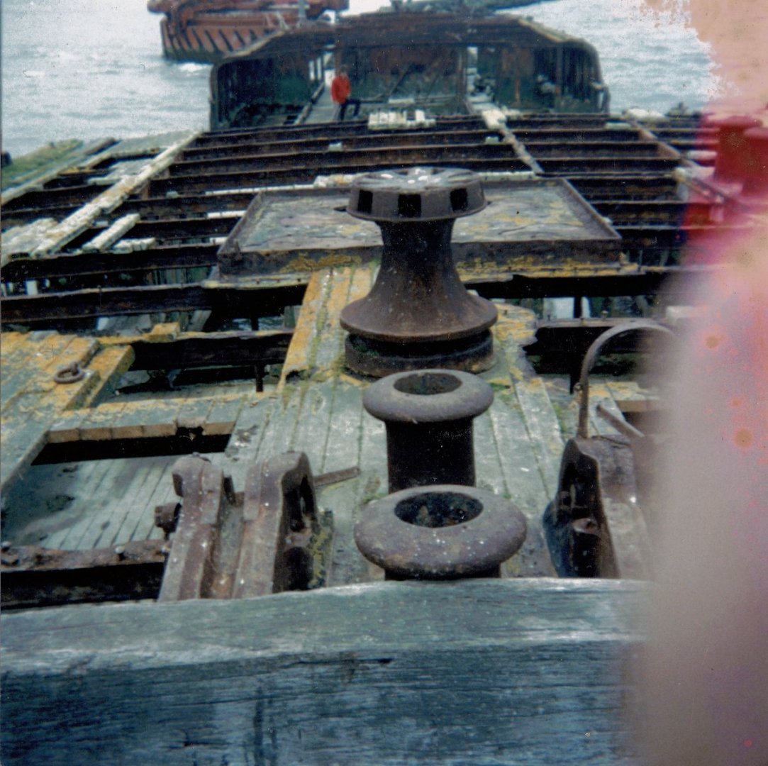
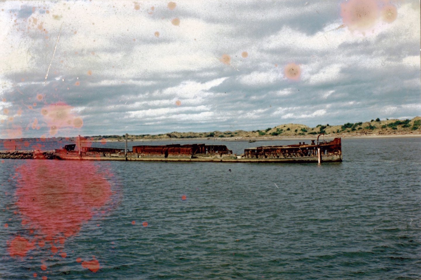
C Nepean Longridge used some of the Cutty Sarks actual teak on he deck of his 1/48 model in the Greenwich museum but he overcame the large pores with beeswax being trowelled into it and polished, having seen the model it worked but the grain itself is sill far to big and the colour too dark, it looks like a permanently wet deck. I still stand by Anigre for raw teak but for polished teak I will be using American cherry stained and varnished, mainly because it has very fine grain lines which almost scale the wood, also I purchased a pack of BBQ smoking cherry chunks which have come from a much smaller tree and the grain in those is even better. By the way I pulled Indian teak of the deck of SS Te Anau in the 80,s for use on a boat I was building and it was still good....smelly but good, 10mm of all sides and good as new. you can see some of it here where we cut it from the bow. This vessel was sunk on this breakwater in 1922 so that is a testament to the wood.
-
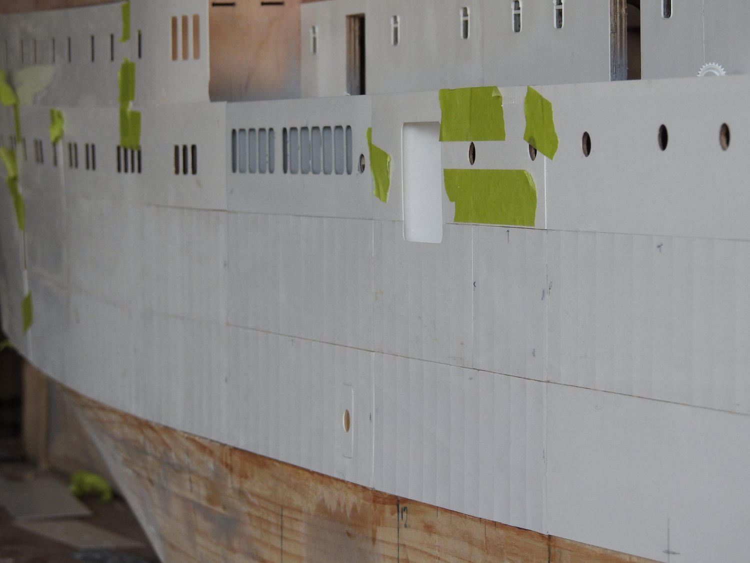
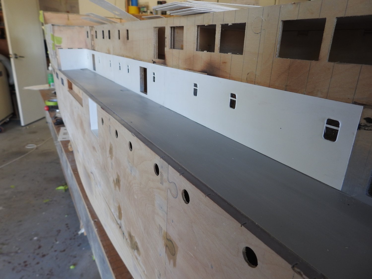
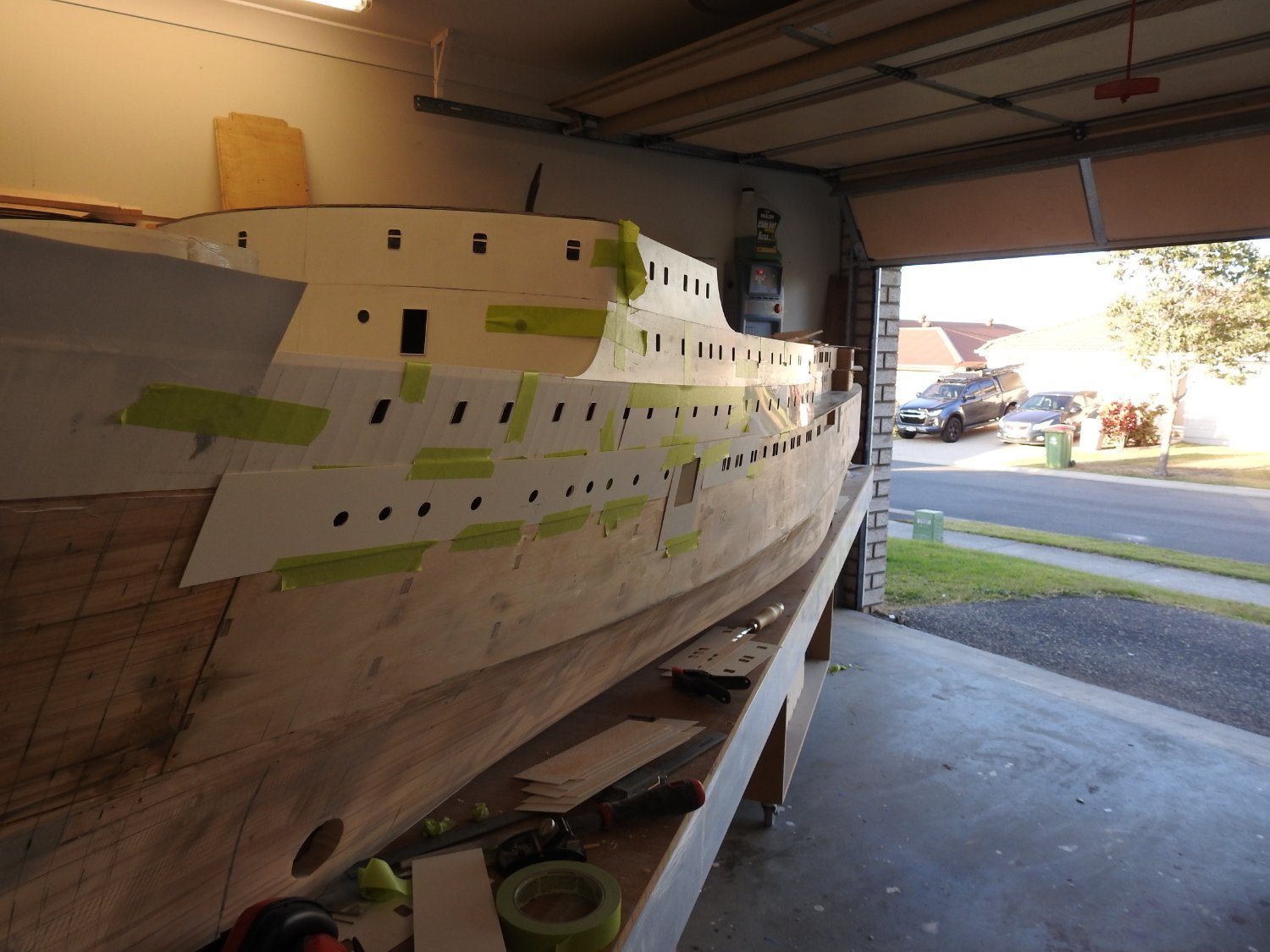
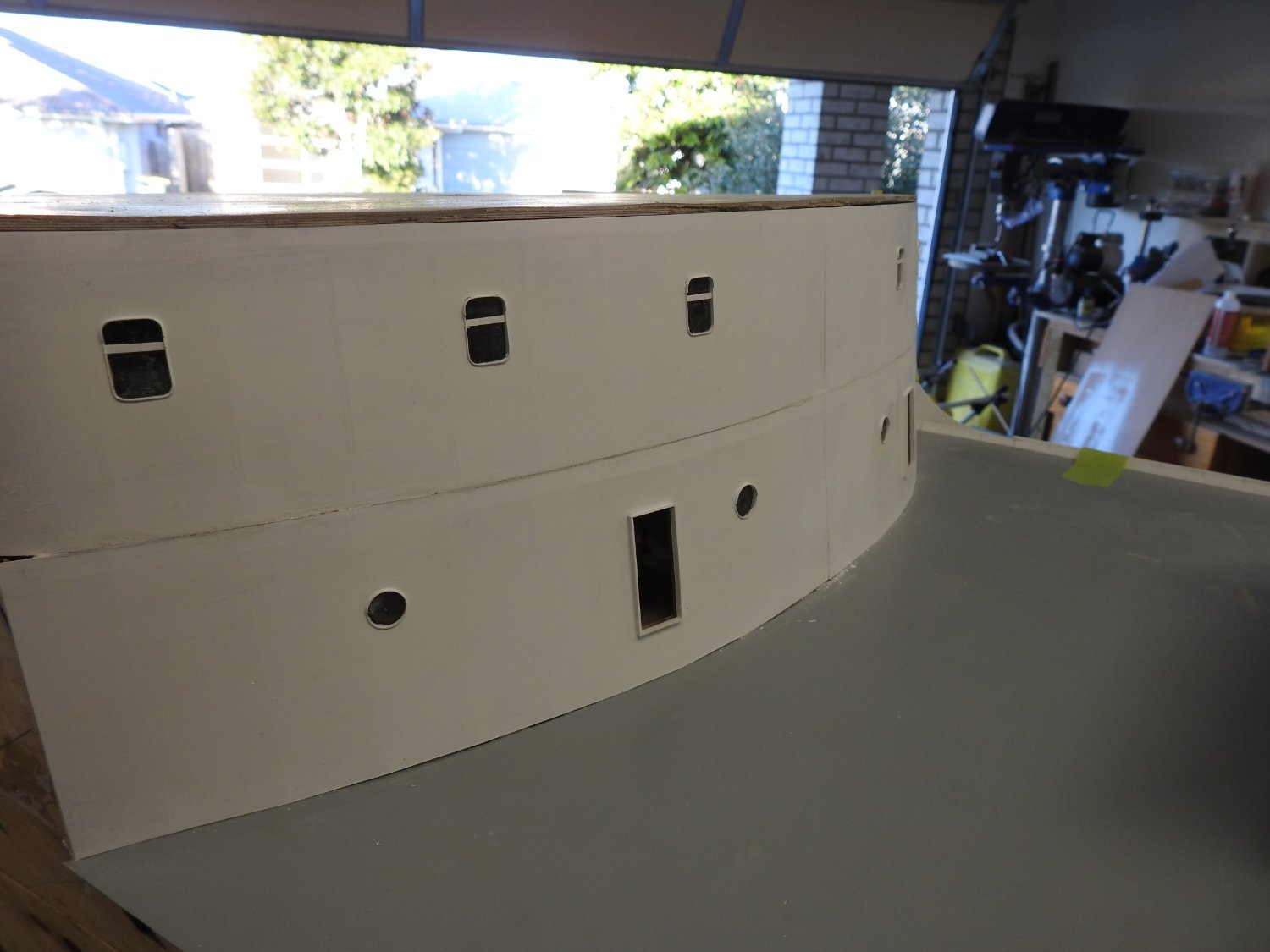
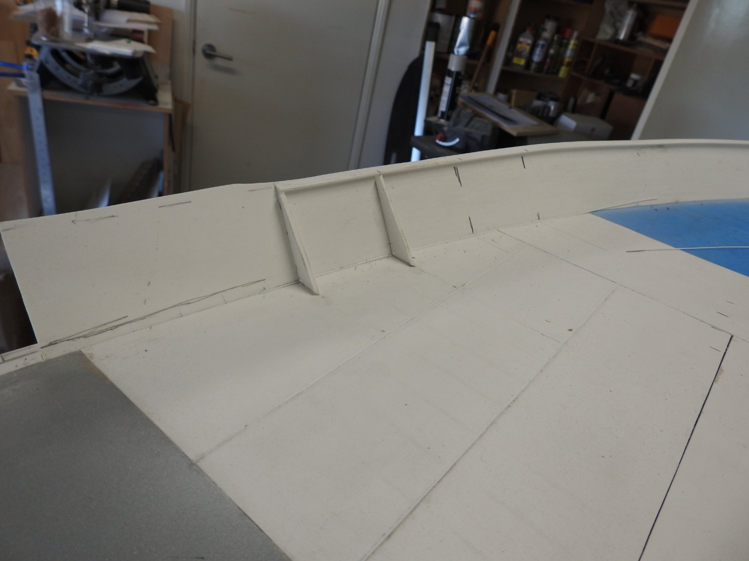
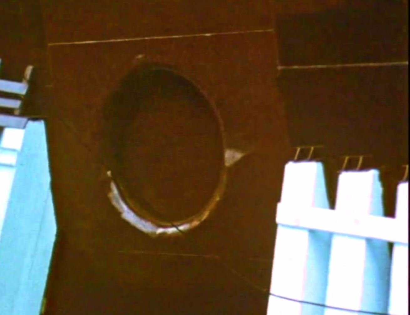
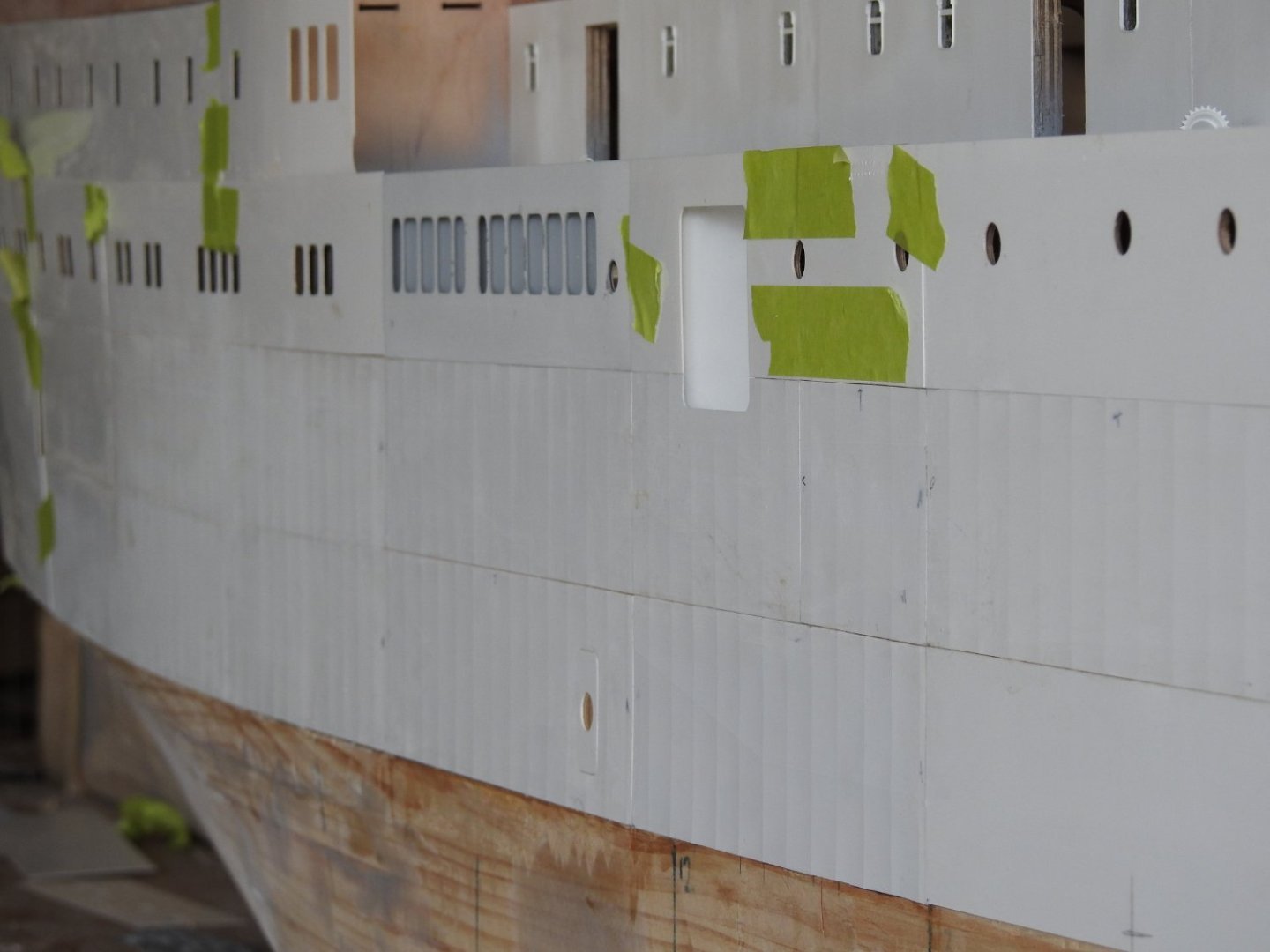
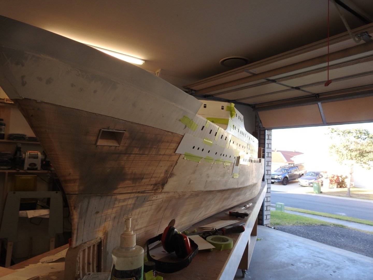
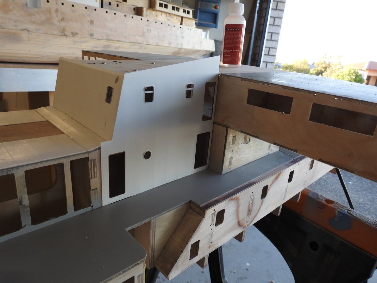
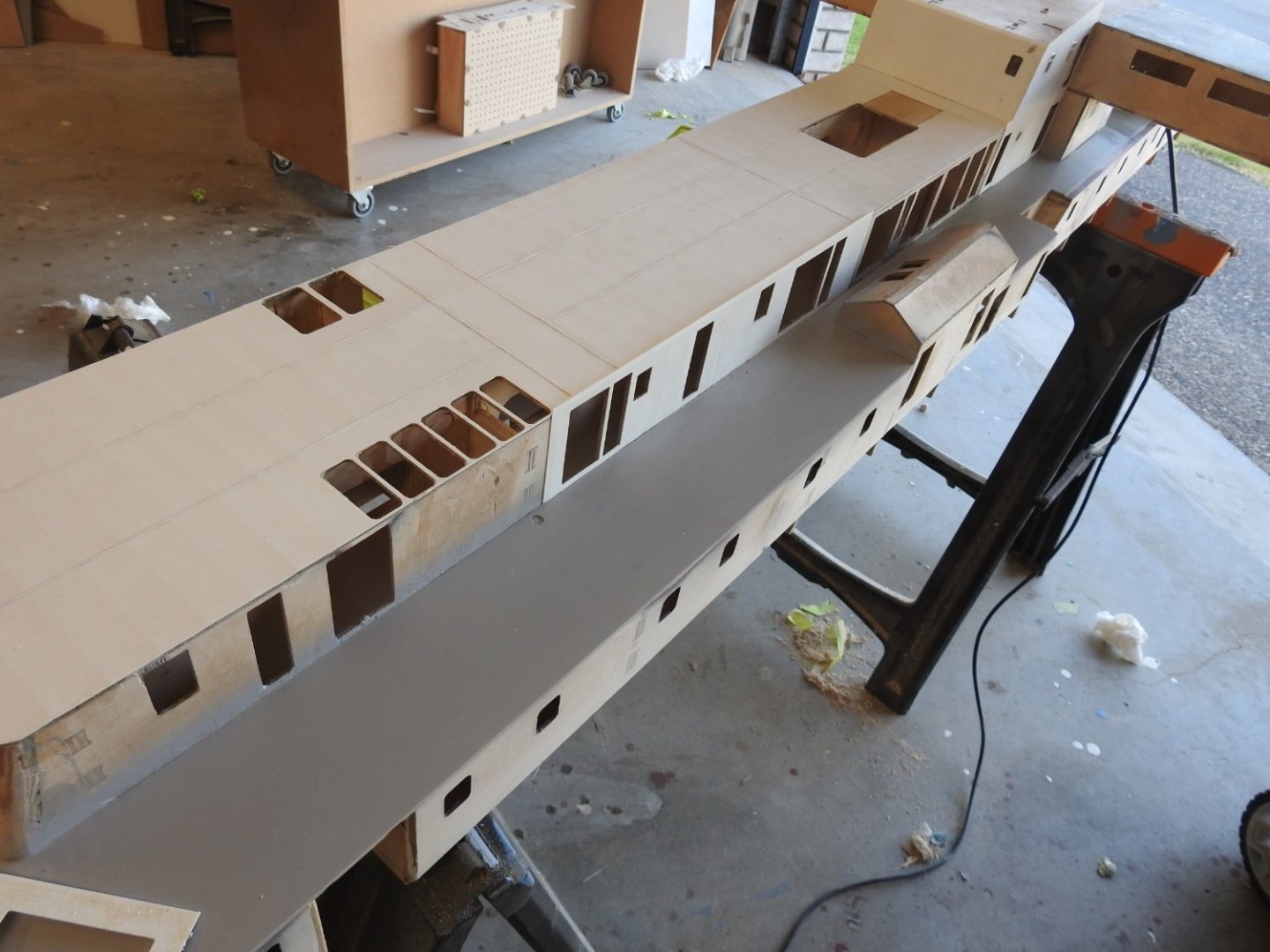
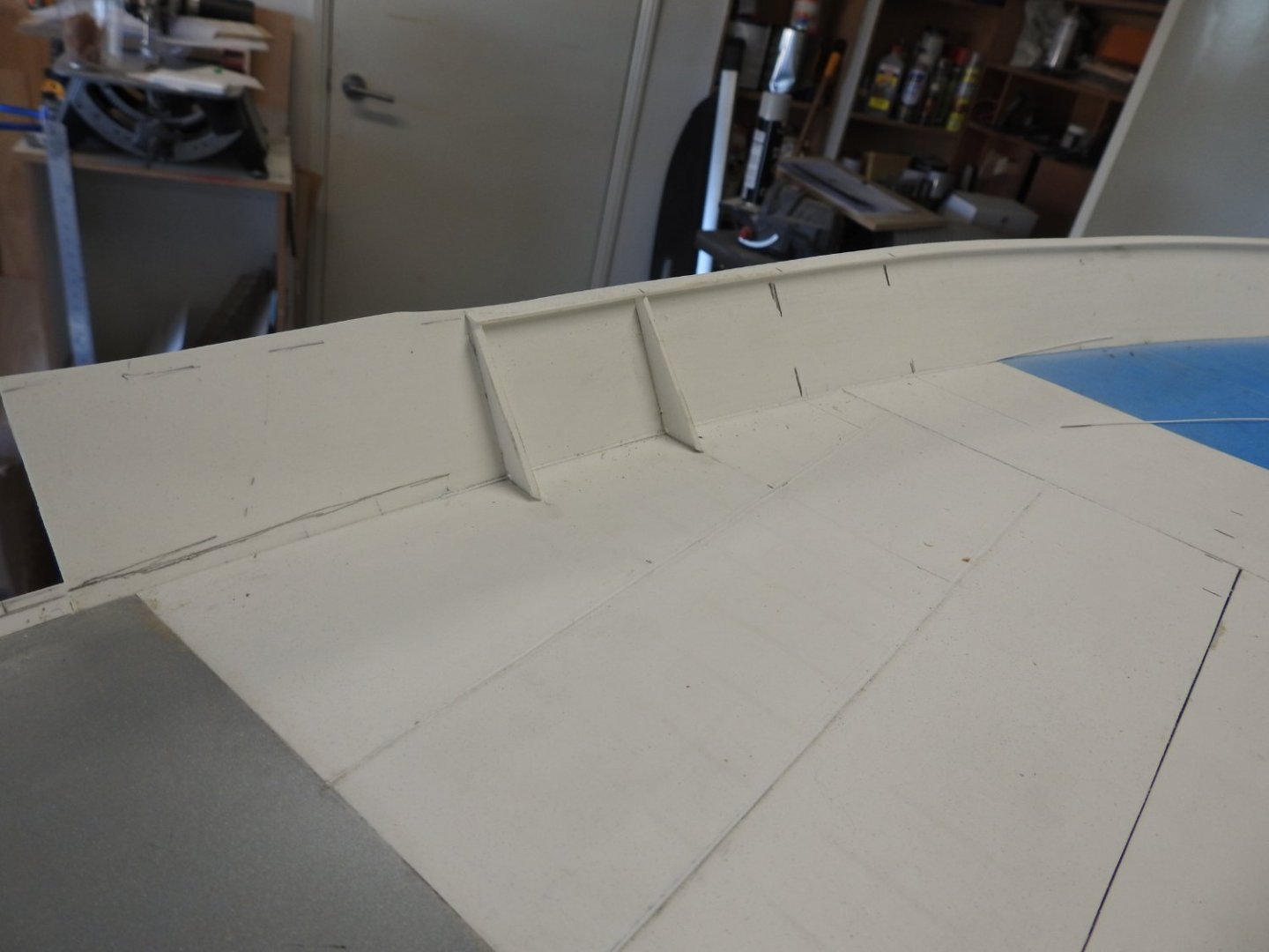
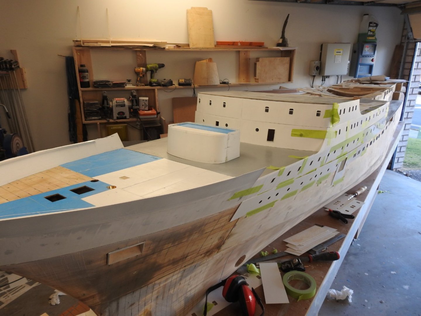
Some updates to the plating and fitting of the windows and portholes. the tinn canning should be apparent as well as some weld seams visible. Note the gaps along the bottom of the Superstructure are all covered by a 6" or 4mm ' wide deck bar that is on all Superstructure parts but because its painted Buff I will pre paint those and glue later, but that will tidy up the joints to be gap free.. Below flanged bulwark stays being fitted. note the notches around weld seams are included. this areas has the weld beads done, the gap to the right is the removable windlass section, the grey part is a rubber compound over he steel which ends there. the bulwark will be cut to a nice curve and into the upstand one the plates are glued on note the holes drilled for the bars over the porthole, this was the ships prison.


- 454 replies
-
- 9
-
-
-
- Union Steamship Company
- Stepcraft 840
- (and 3 more)
-
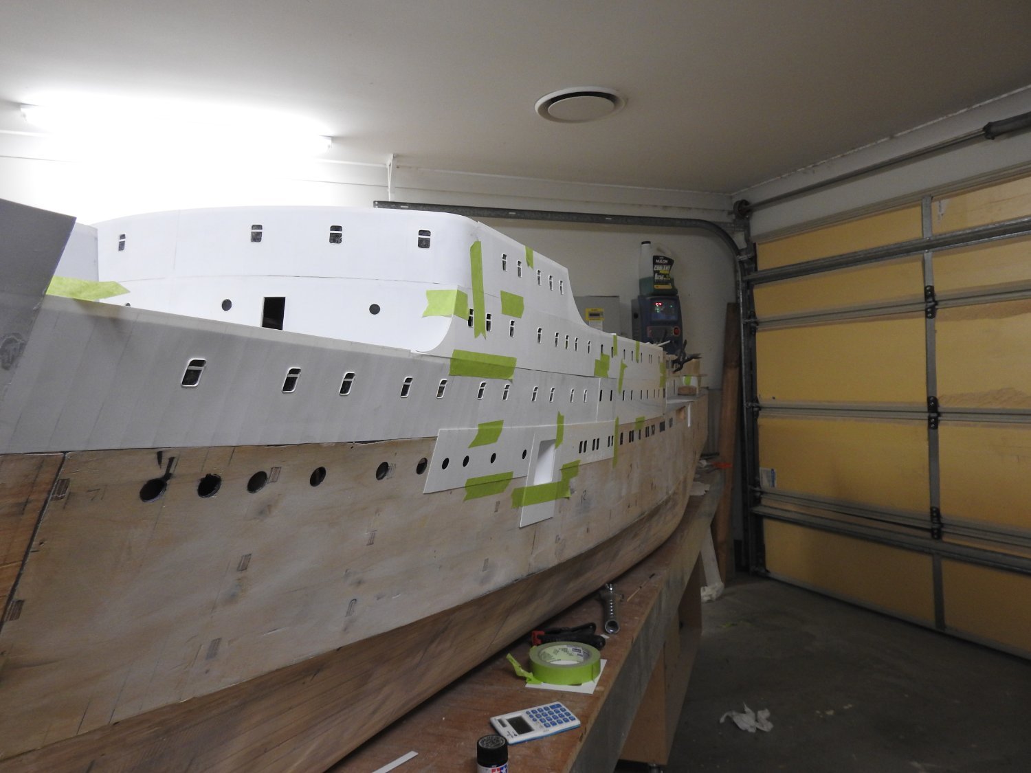
I wanted to share the process for the tin-canning of the plates now that I think I have found a good result I am very happy with. After many trails and failures the result was insanely easy in the end. I want to start by saying I have done a lot of tests with Styrene, not evergreen styrene BTW but another commercial kind and glued it to ply and exposed it to some extreme temp jumps, ranging from 20 degree to 6 degree over a few months now and have had no effect, this might have something to do with small plate sizes and the seam being glued into the gaps, thereby creating an expansion joint of sorts but none the less I have had no issue and that's without paint. I did not exceed direct sun exposure time of 2 hours and not on super hot days which I would not do anyway. The biggest plate is 290mm x 65mm , most are about 200mm x 50mm just for reference. Right to the plates. Each plate is cut from my 3d model on the CNC including windows and doors, some might be hand fitted if something changed, but after it's fitted to the model I transfer framing lines to the back side of the plate, not just frames but stringers ,girders and longitudinals in general, if it shows on the ships skin, mark it on the plate. I then cover the good side with a blue protective film to keep the surface in good order until priming time. If you don't use CNC just draw the plates out on surface and trace them through to the styrene and cut them out ..5mm is still transparent enough to see through...just. I then very very lightly scrape the front edge of the plate where a weld seam will be at a 45ish degree, just enough to see a thin white line around the blue, this forms a very small groove when 2 plates are glued side by side that the ,5mm styrene rod is glued into to form the weld seam. Once this is done I lay the plate face down on a hard rubber mat and the magic happens, I roll over the lines with a Pizza cutter!!, vary the number of times from frame to frame and press hard!, sometimes I go twice, sometimes 5 times,. use a wood block to run against to keep the cutter straight and once done the plate is ready to be glued to the model with medium thick Starbond Cyano. I first expected the Pizza cutter to just create raised lines but buy having the rubber underneath it creates the exact dished profile!, The surface is near impossible to keep free of glue smear from Cyano when a little squeezes out the side but due to it being thicker we have about 1 min to quickly wipe the edge and run around the plate with a scraper to clean any small bead of squeeze out. The results speak for themselves. I shot his with garage door open so the strong backlight makes it show up but it's subtle. I should also add I tried using Techni glue to glue the Styrene which is a top notch commercial epoxy but even with keying the styrene it pulls away with a bit of effort, the Starbond Cyano however is a different story, even with no keying and gluing the glossy side it tears off in tiny chunks and will NOT come off.

- 454 replies
-
- 9
-
-
-
- Union Steamship Company
- Stepcraft 840
- (and 3 more)
-
My parents both worked at the Union Steam Ship company on the corner of Customhouse quay and Johnson st, mum recalls a woman rolling up the street like tumble weed,unable to stand up and dad coming down the Nauranga gorge with the torrents of water in the gutters going uphill!
- 454 replies
-
- 2
-
-
- Union Steamship Company
- Stepcraft 840
- (and 3 more)
-
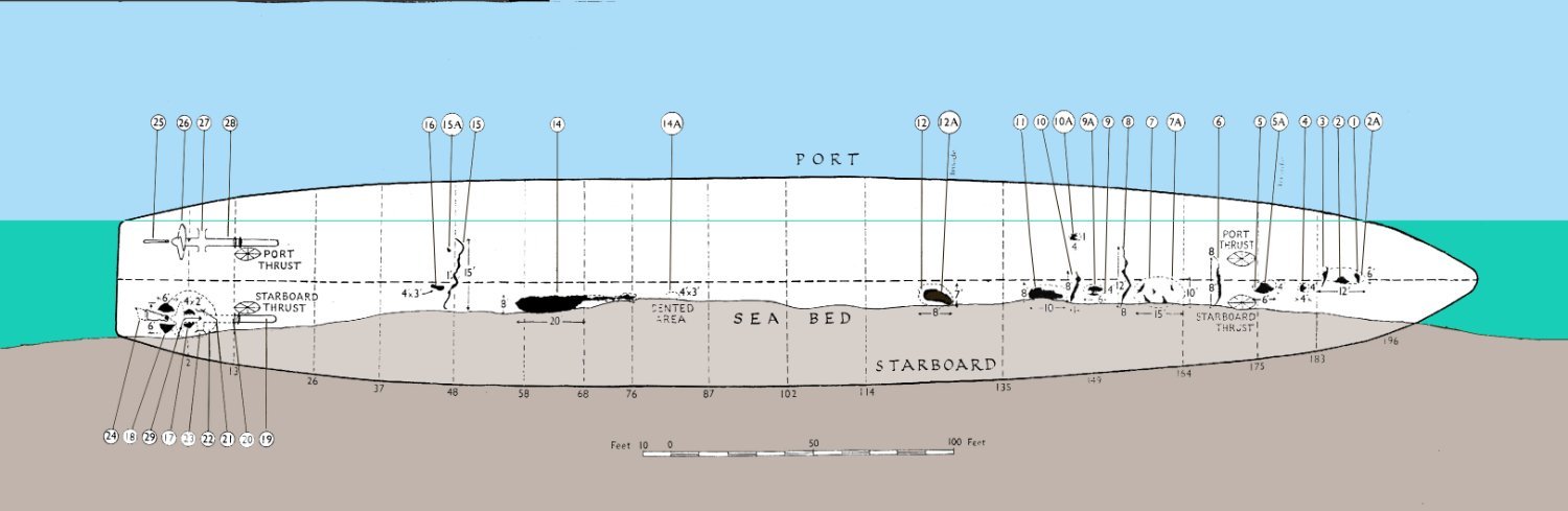
No because Wahine was exempt from needing towing, she had lateral thrusters and a bow rudder to manoeuvre and did not require a tug unless the wind was extreme. The ferries even now don't need them either.
-
Not sure if I have posted this but this is from the Navy survey of the hull bottom.

- 454 replies
-
- 3
-
-
- Union Steamship Company
- Stepcraft 840
- (and 3 more)
-
We recently found the wind speed measurements from 8 points around the city as used in the enquiry, at the time of her being exposed to that and being pooped and subsequently broaching in 30m waves the gusts were 275kms! they were among the archives data we sorted last month
- 454 replies
-
- 1
-
-
- Union Steamship Company
- Stepcraft 840
- (and 3 more)
-
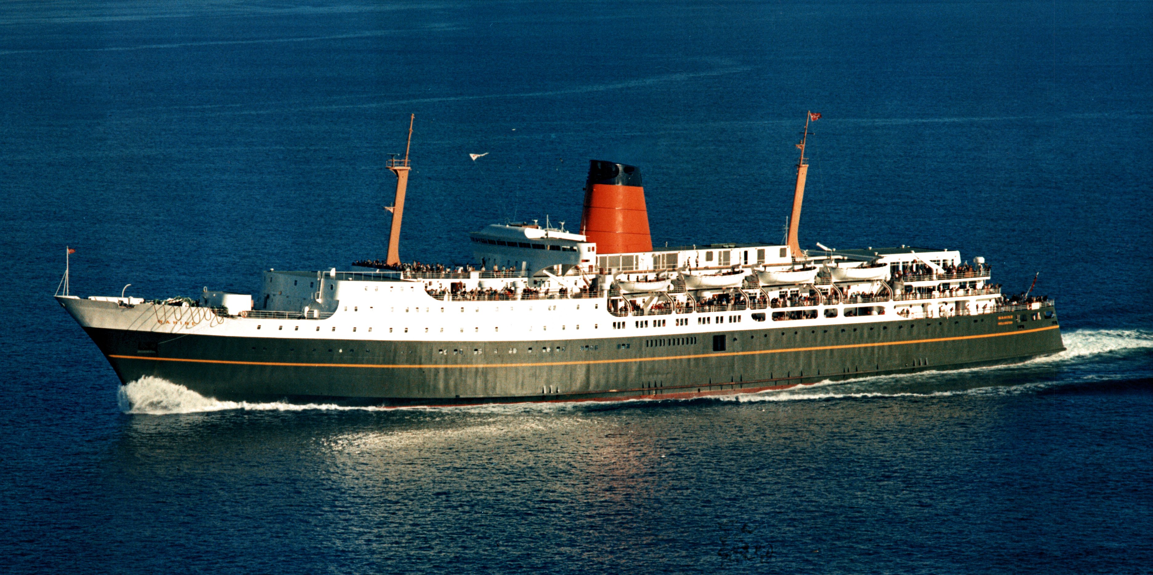
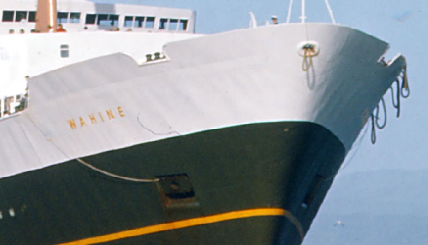
I have no idea but its in a few shots after she was in service a while not in early days though. I have a shot by Warwick Pryce I have cropped ,it's from Murrays old site but here it is in more detail
- 454 replies
-
- 2
-
-
- Union Steamship Company
- Stepcraft 840
- (and 3 more)