HOLIDAY DONATION DRIVE - SUPPORT MSW - DO YOUR PART TO KEEP THIS GREAT FORUM GOING! (Only 20 donations so far - C'mon guys!)
×
Richard Dunn
-
Posts
529 -
Joined
-
Last visited
Content Type
Profiles
Forums
Gallery
Events
Everything posted by Richard Dunn
-
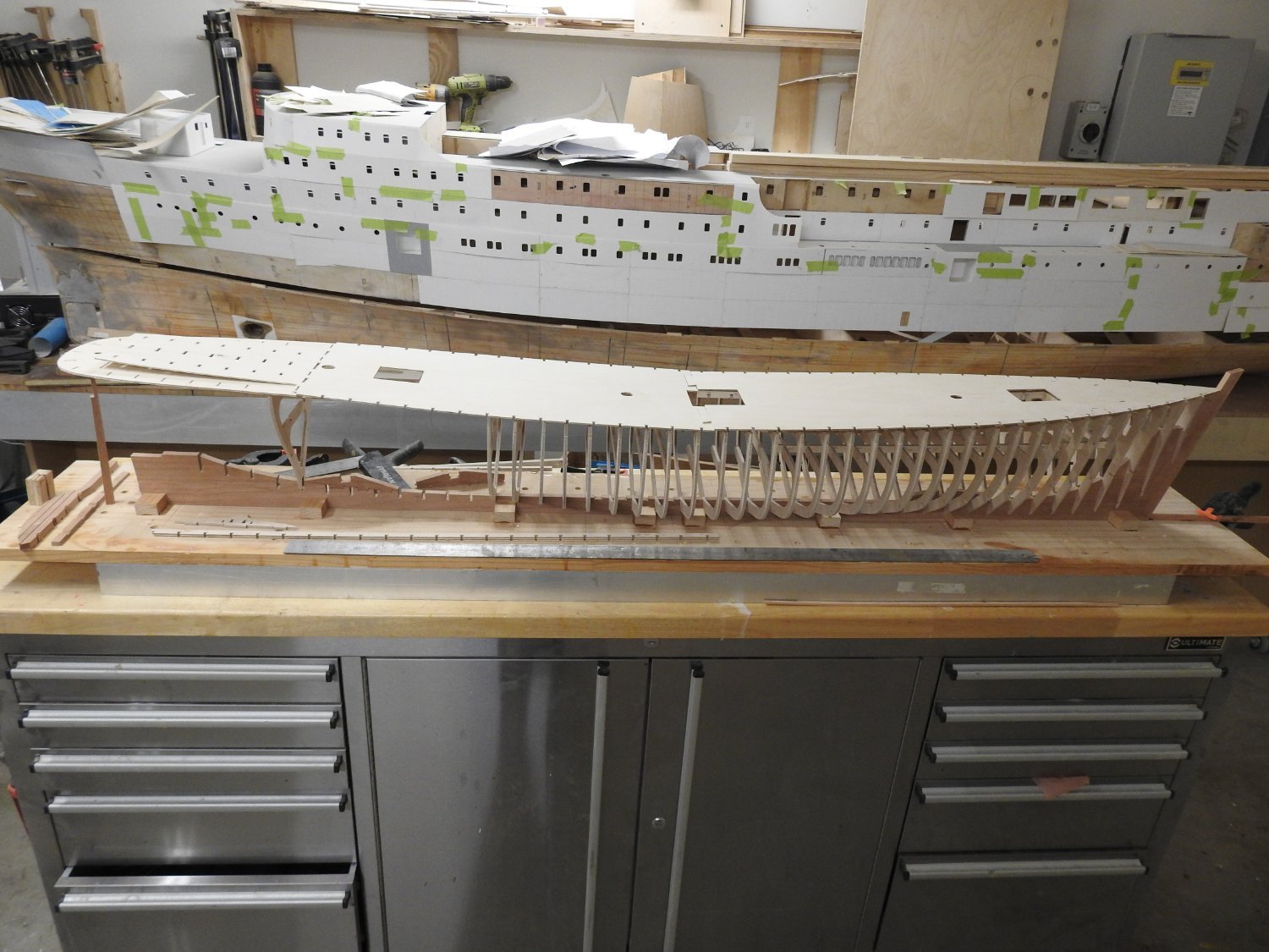
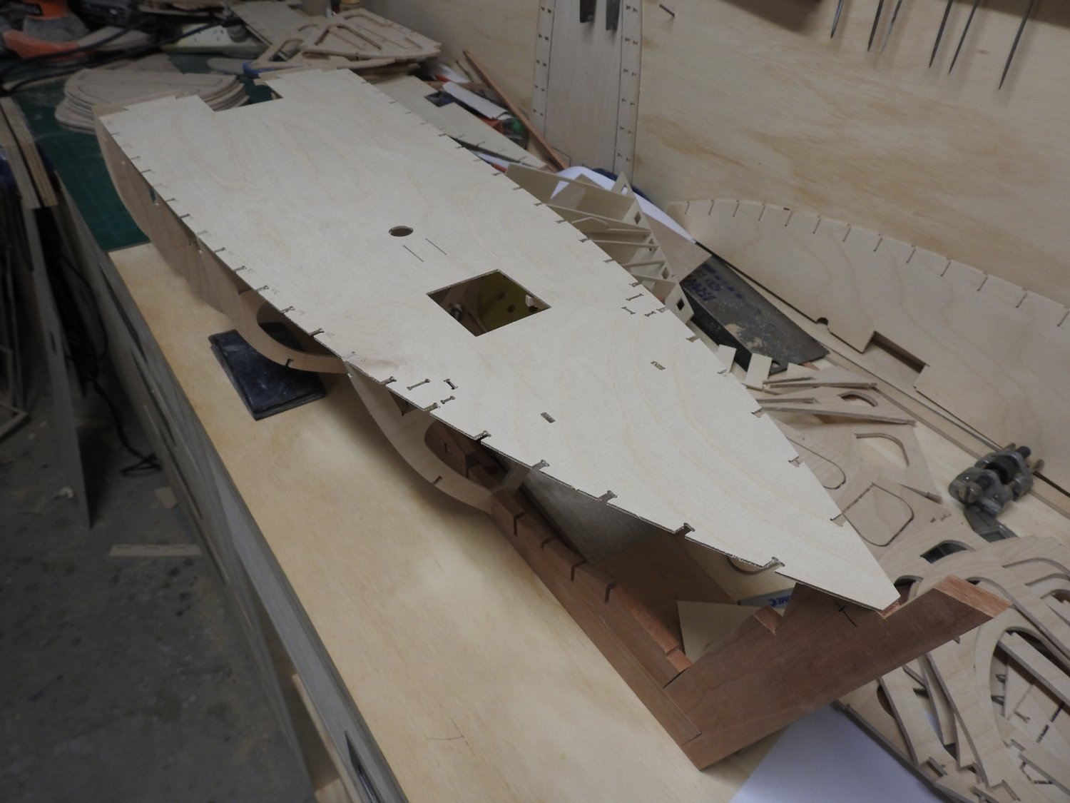
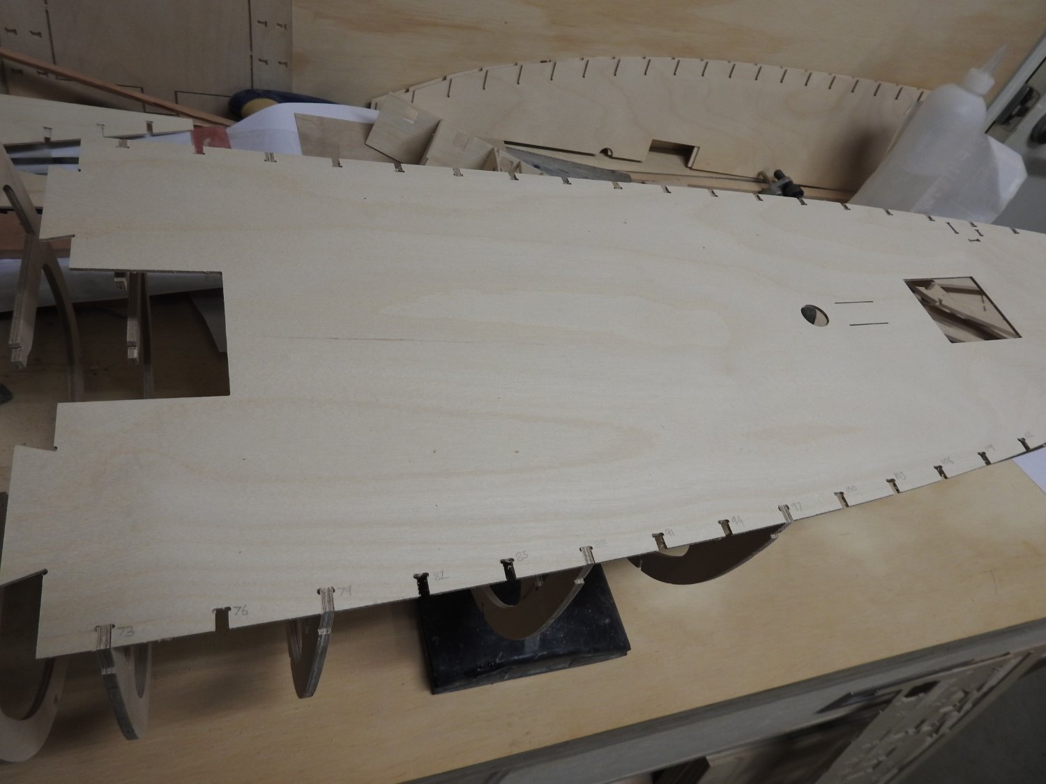
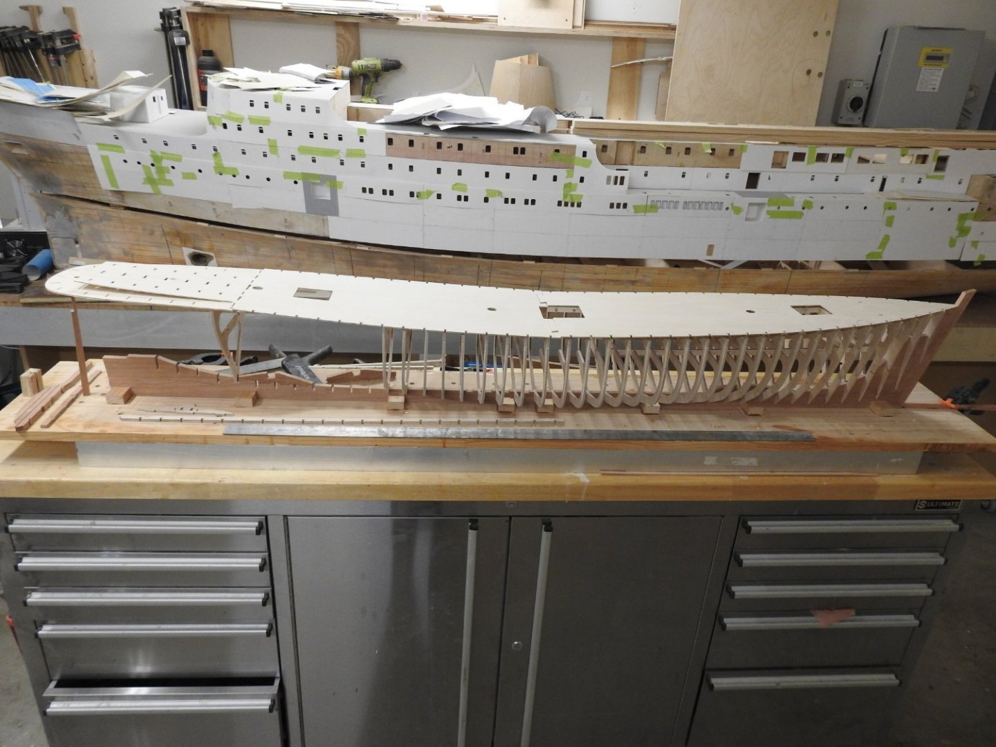
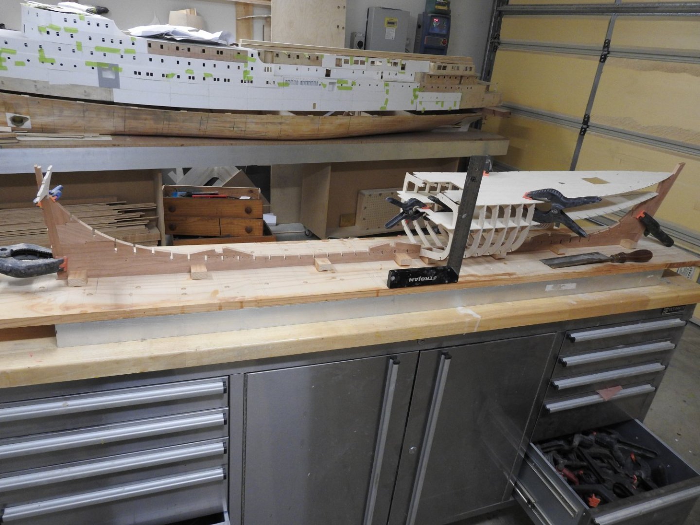
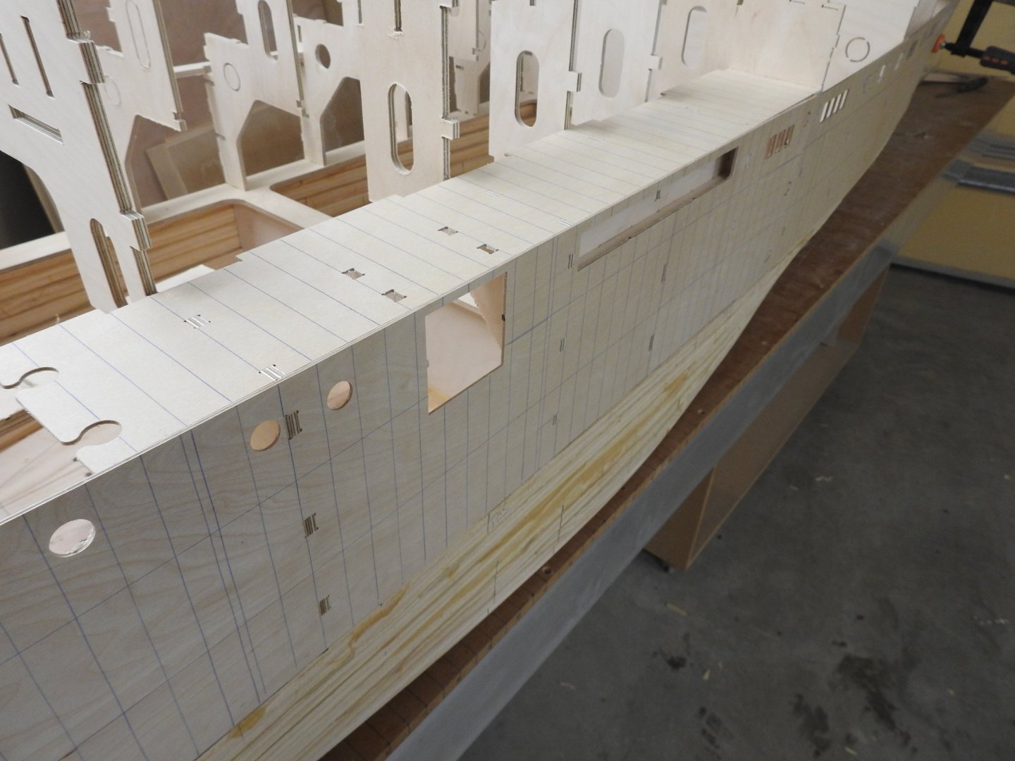
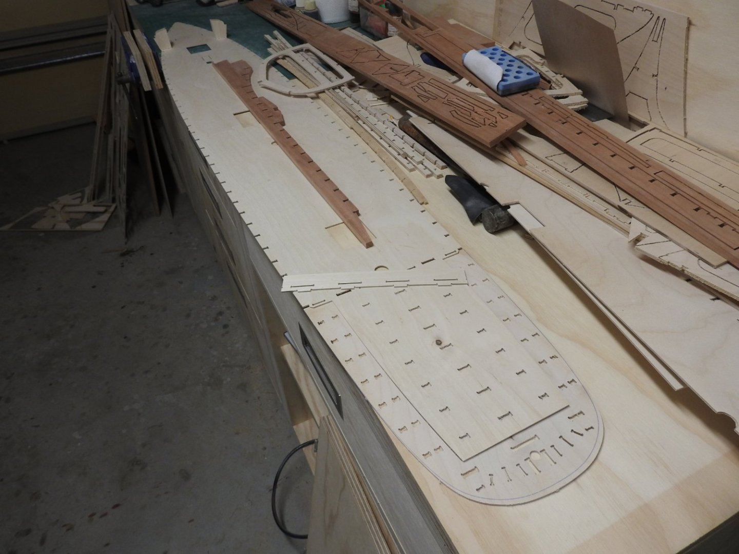
 Just laying the main deck on with a 1 meter rule next to hull for scale.
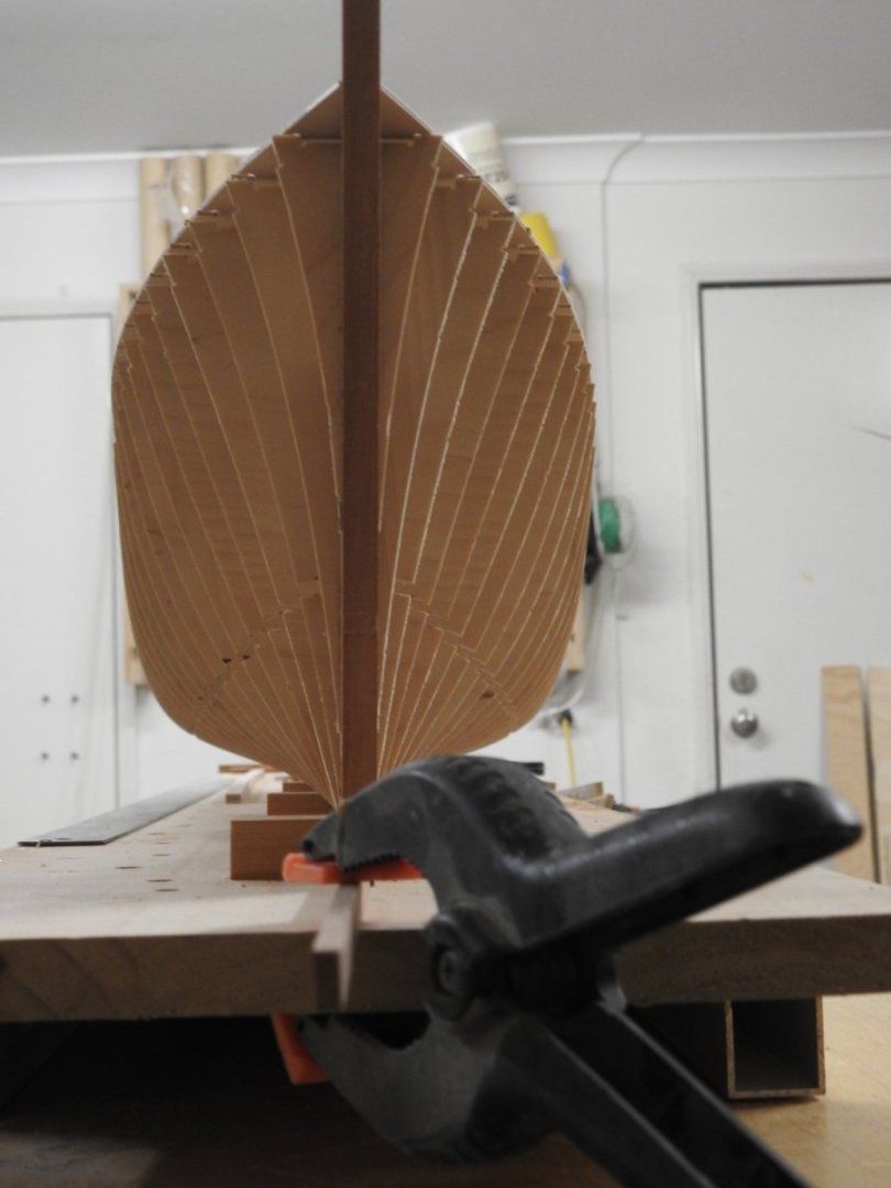
-
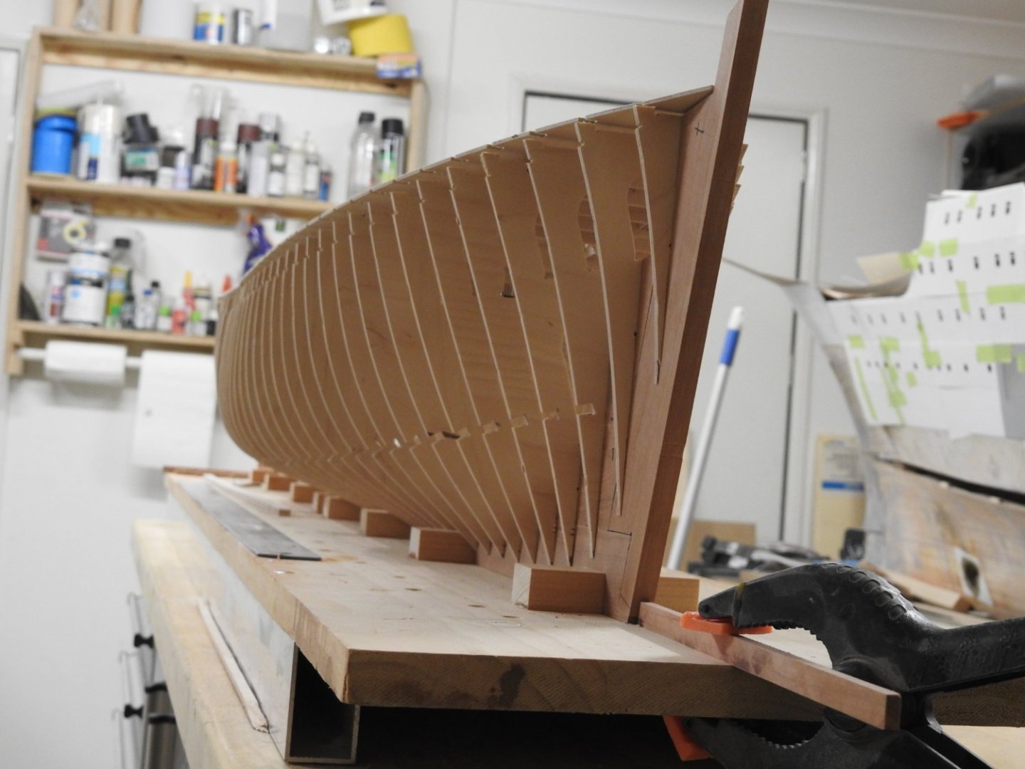
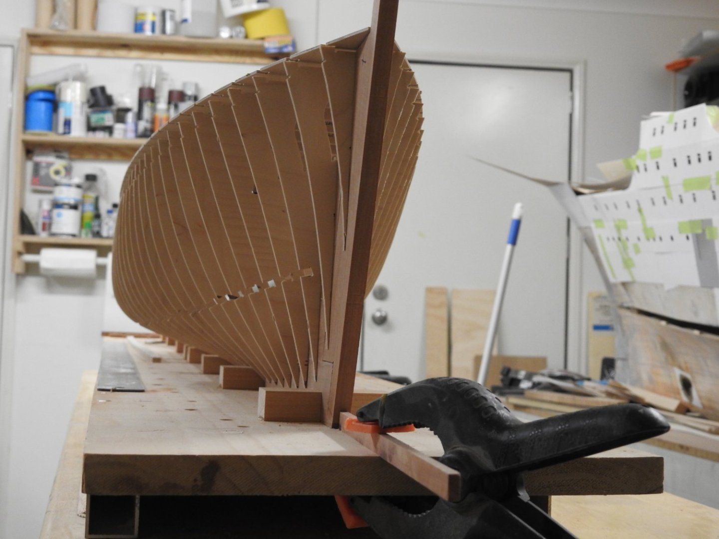
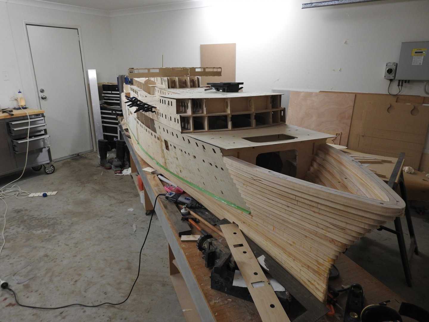
Nearly all the forward frames are fitted now. Note the fair line of the main deck along the sheerline, it's a pretty good indication of the accuracy. It's looking less and less likely I will make this a kit, as I suspected it's too large for most, I had a number in my head of 10-20 requests. I might look at selling the cad files so it can be cut by the buyer.


-
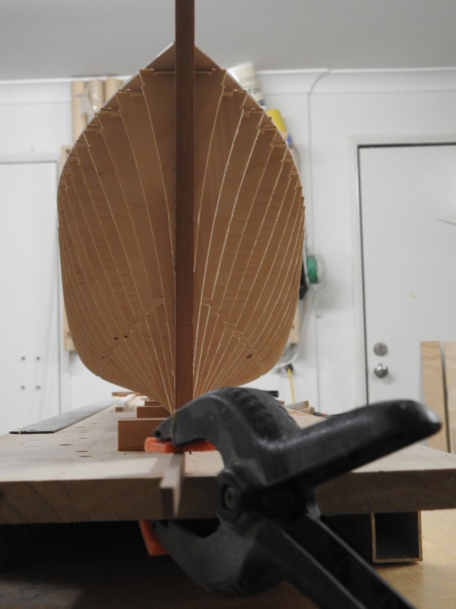
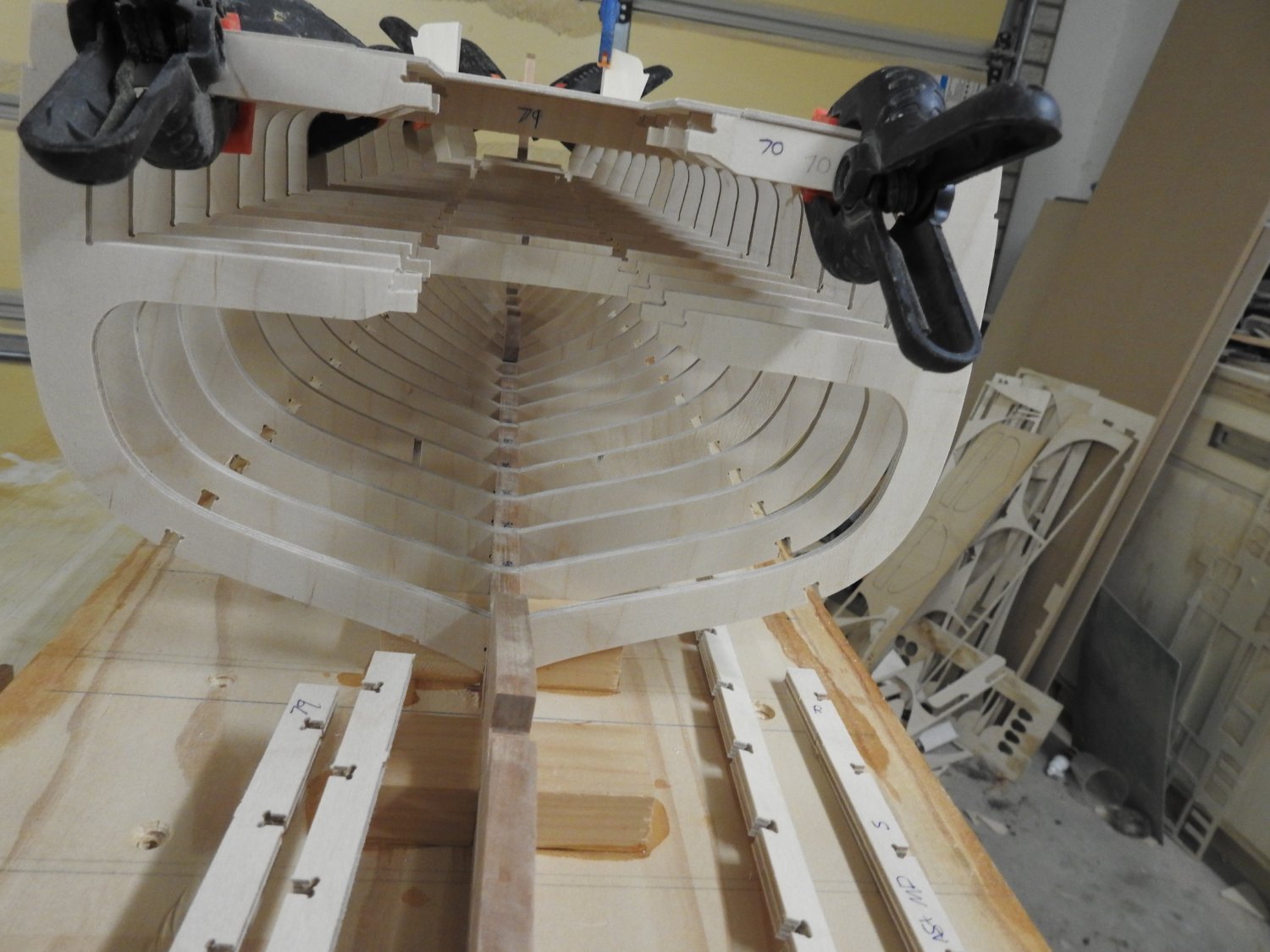
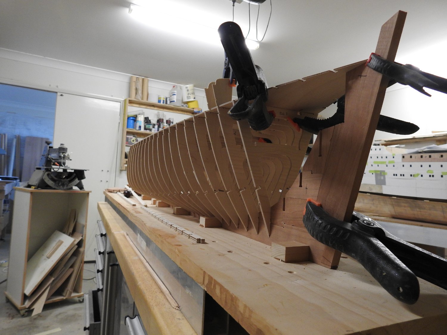
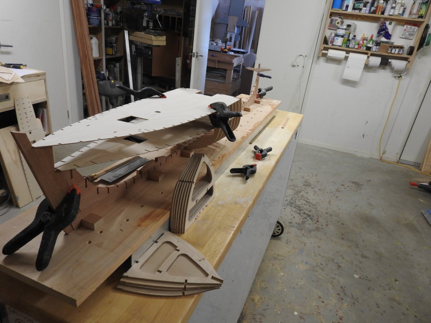
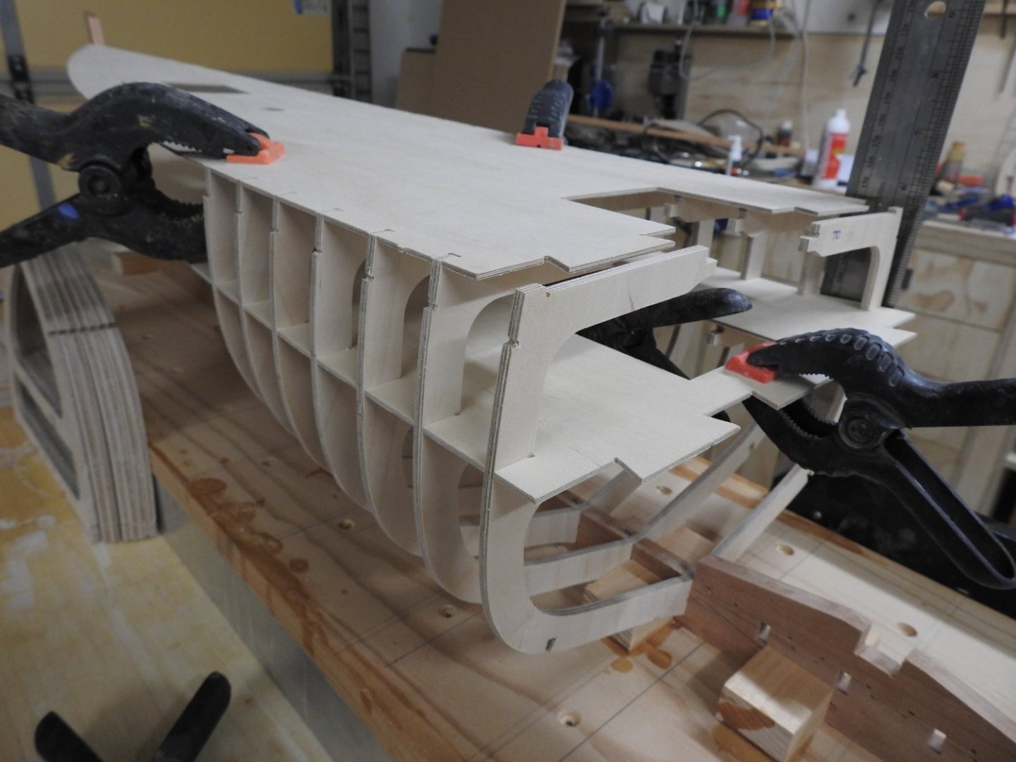
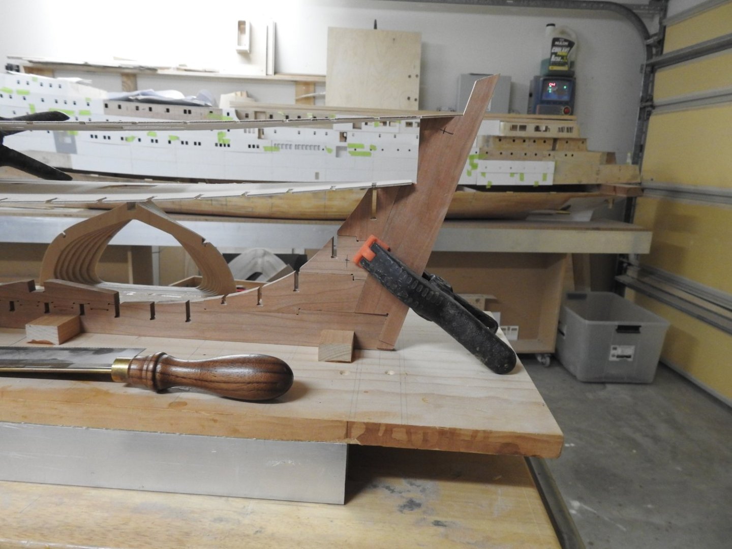
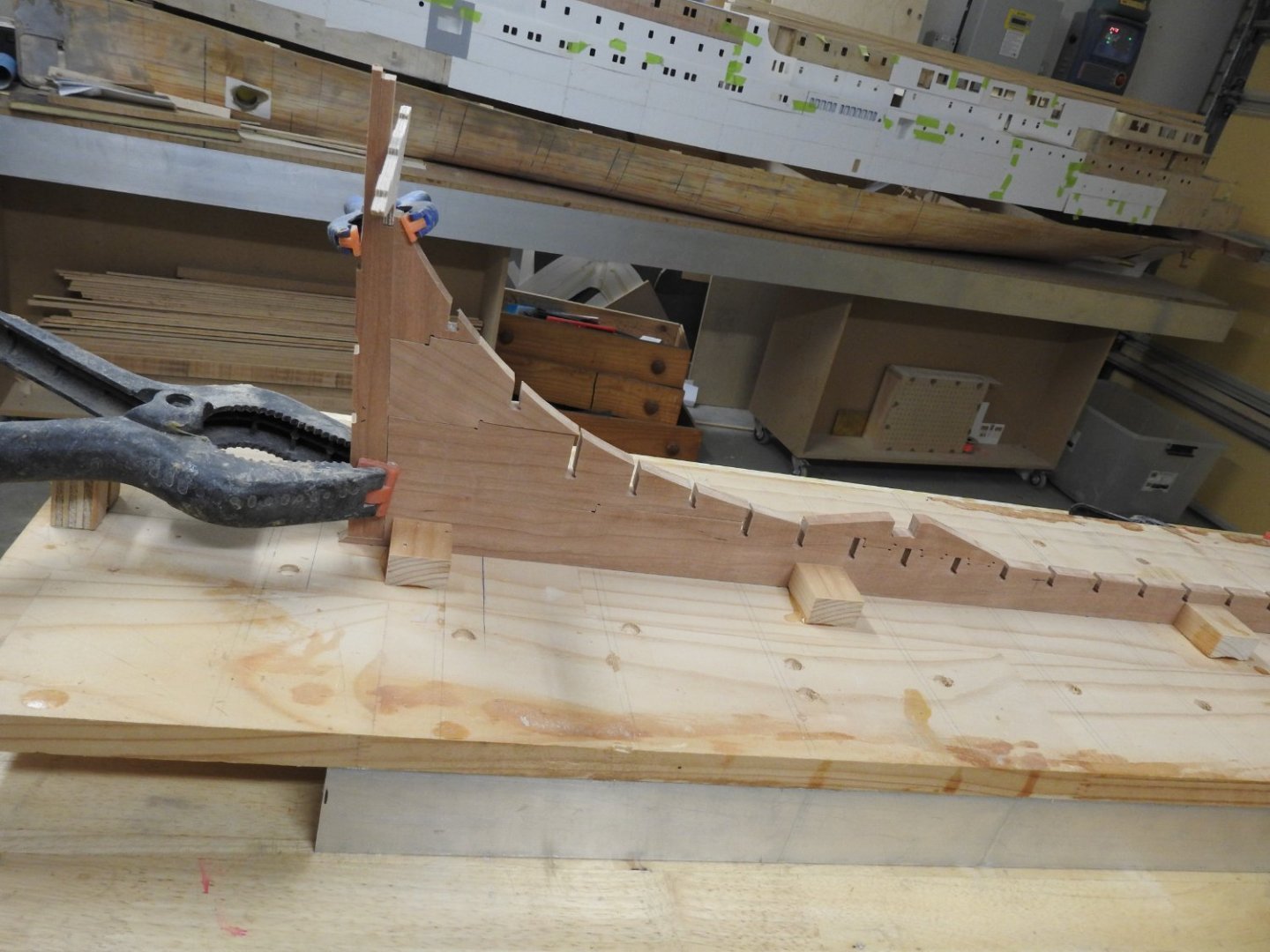
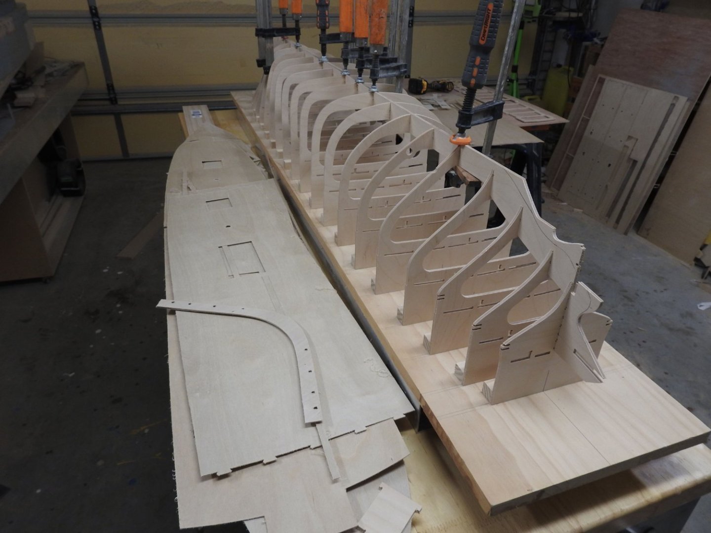
Starting to test fit all the parts and dry assemble. nothing is glued or forced together so a few little gaps but its fairly good, I am happy Stern deadwood and sternposts The Forward Deadwood minus the Stem post and cutwater Frames 70 to 88 dry fitted and decks fitted for checks And lastly a straight brass round to check alignment fore and aft of mast holes. Once I have done this for all the frames its time to cut the rabbet and start gluing


-
I hope this answers your question about the fit of the decks.. side to side at least.

-
Here you go https://www.dropbox.com/s/nq8liinoh9e4gqf/Hull Form Basics in Rhino.mp4?dl=0 If you have any issues with video playing you will need to use VLC media player, its free
-
If you go into the Cad section I did a live workshop on the Rhino basics for hull form a couple of years ago.
-
The build so far is here
-
I use Rhino which is used to design ships and my background is designing and doing structural modelling for ships and some naval vessels. I also use it to design and concept furniture. I use it as well in my day job now in TV Film and games modelling. so yes I have a lot of experience in a professional capacity. I us a tool in Rhino to develop non developable plates and shapes that are not able to be "unrolled" you may know them as ruled surfaces, but Rhino has tools called squish and smash which do it and allow for stretch and compression. its good enough to use in ship plates productions so.... https://docs.mcneel.com/rhino/5/help/en-us/commands/squish.htm If you look at my SS Tamahine build which is assembled and made the exact same way you can see the fits and the developed inverted stern parts fitted. Below is Tamahine note stern wrap part on bench, the curved part. Fitted On the TEV Wahine which is my personal project which is 4.3m long the plates are also developed with the same tool See below, the most advanced structure I will ever do .
.jpg.d01b1d56c4eb0774fdc5ec99b2cc3260.jpg)
.jpg.28c4aaa99c91c9ff418616d36172d3f7.jpg)
-
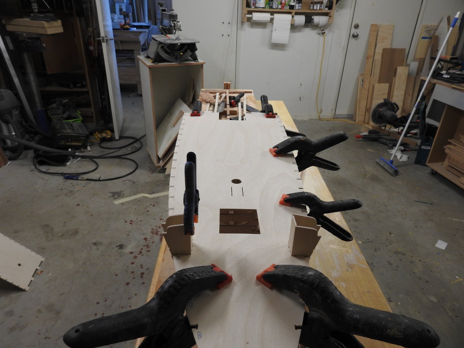
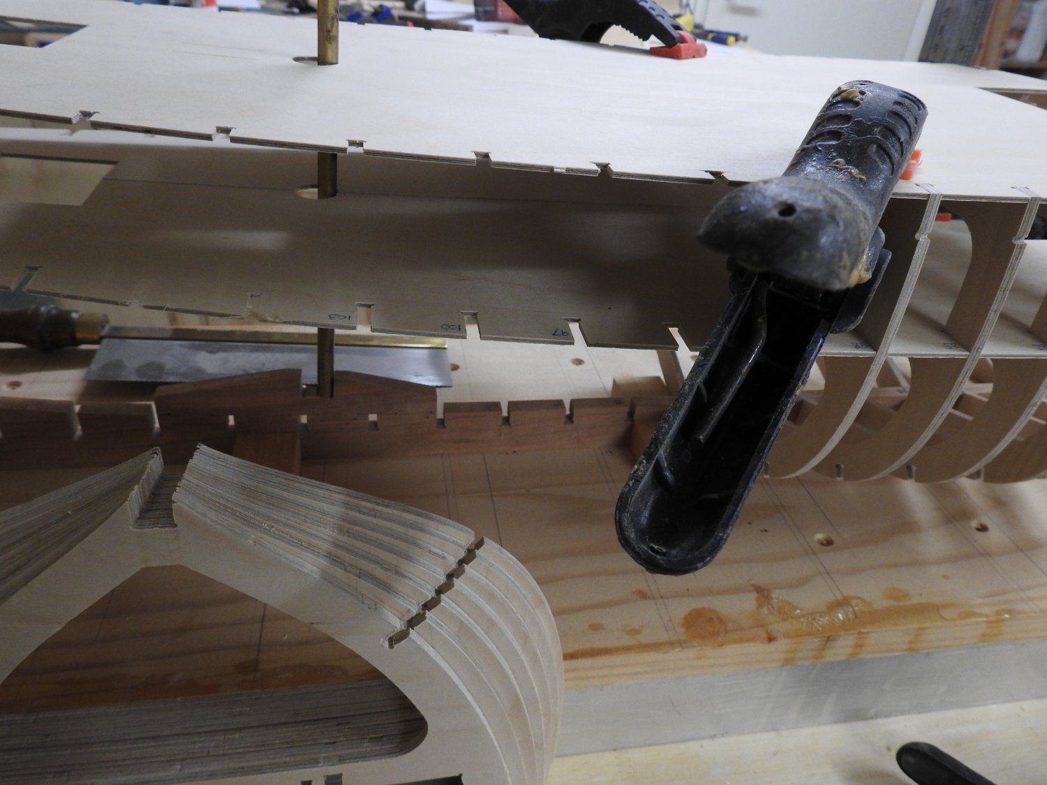
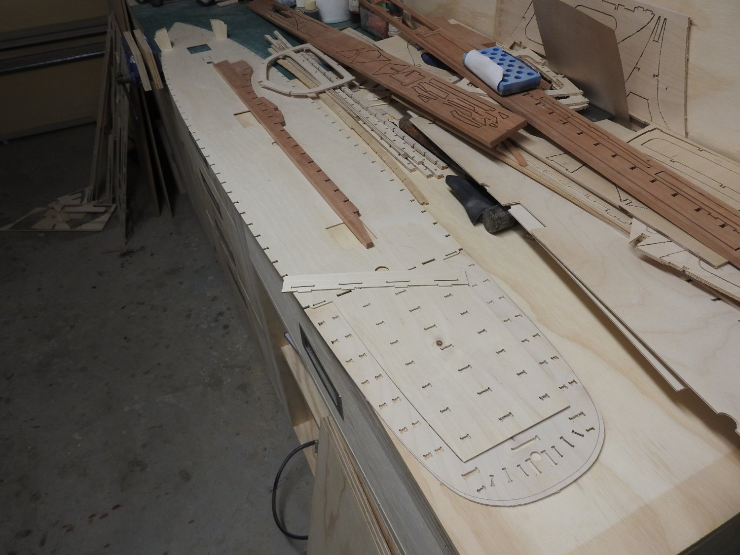
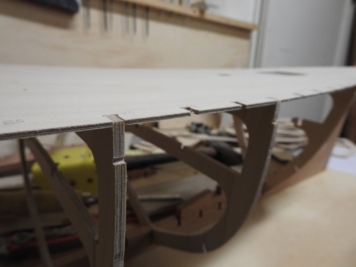
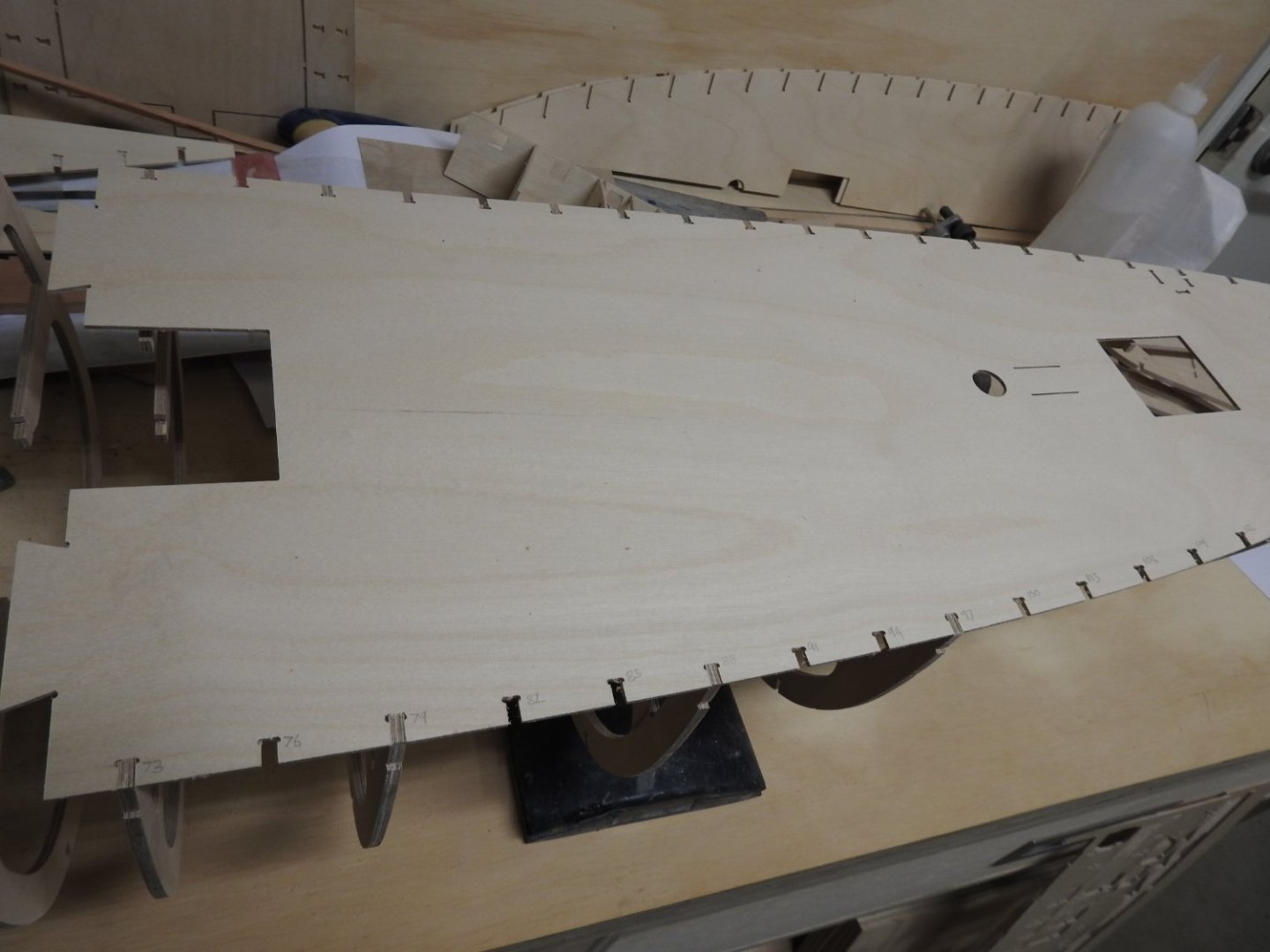
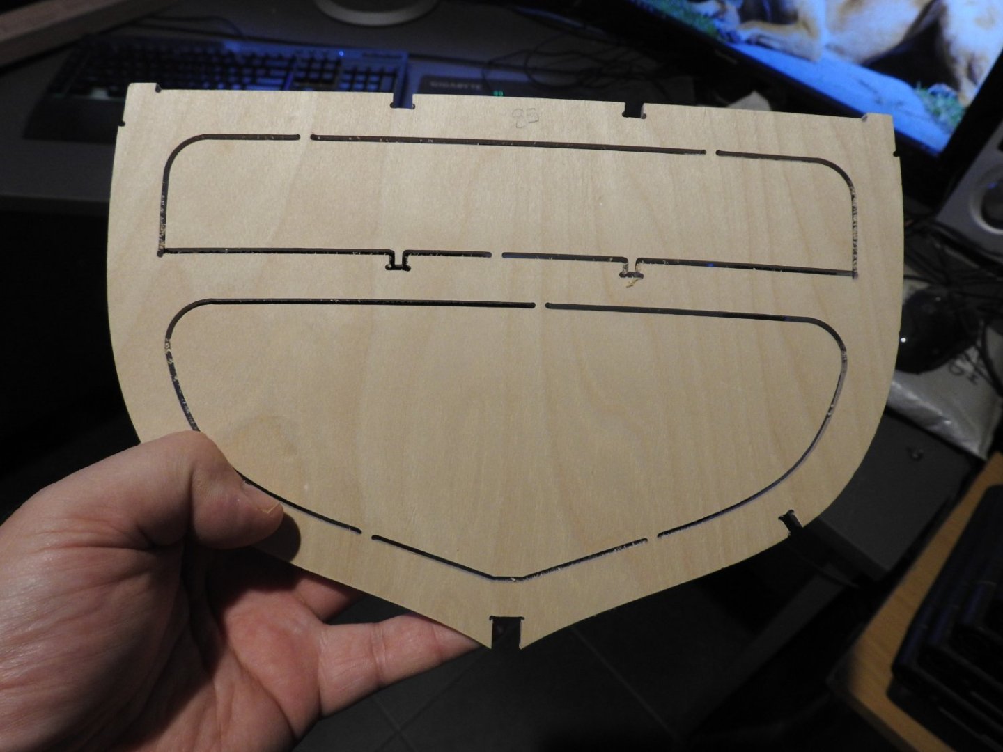
I have started to clean up the parts and dry fit all the joints. Below is the main deck, on it rest the forward half of the keel with the fore mast step and first part of the deadwood fitted. A close up of the joints showing how well they fit, notice also the fit of the dovetails joining the deck parts. Below are the heads fitted into the slots, the stay plate slots are also shown forward of mast.
-
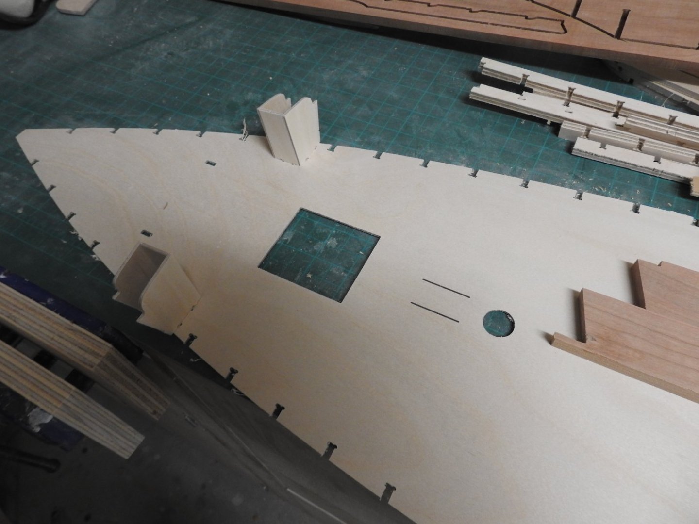
That's right and in this case the inner panelling will need to be filed flush to the hole anyway so it has to be done, not to mention a corner from a 2mm cutter is gone in 2-3 strokes, its pretty small, the whole square hole is only 11mm.
-
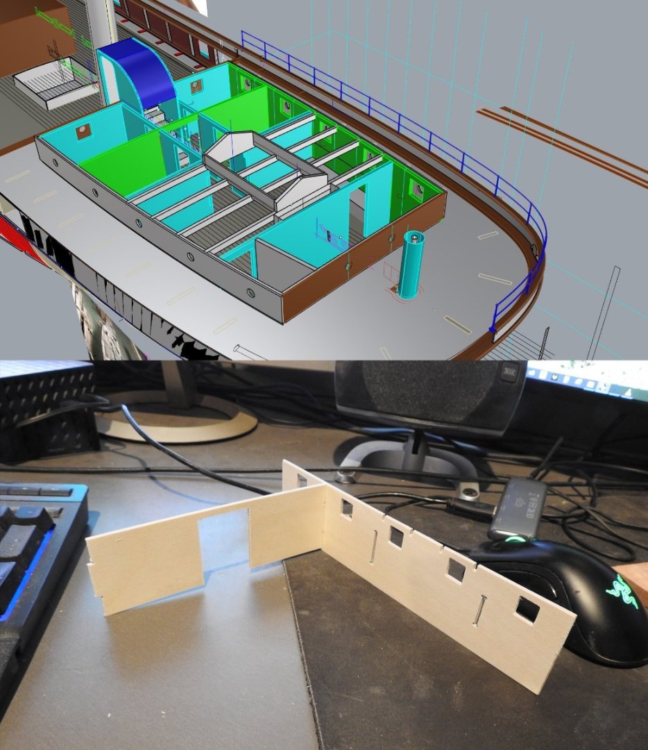
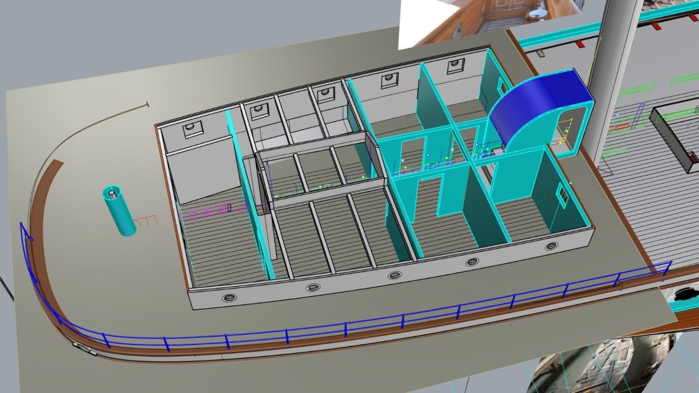
The first fitted 2mm ply parts, interior walls of Coachhouse, green in cad image, the saloon size can be gauged from this. The porthole openings are square because the inside is and if wanting to panel it its done.
-
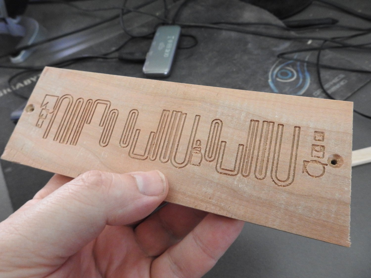
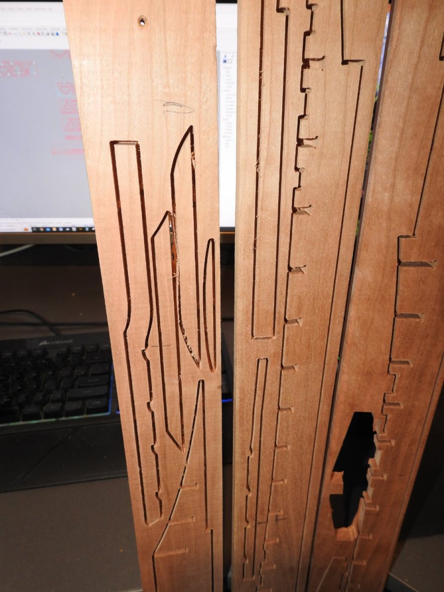
I have had great success with cutting the square mouldings which range from .65mm and 1mm wide, of course these will be cut from thinner stock or narrow planks so they can be released by running through a saw but the point is the accuracy is there. next I will try a v cutter pass first to create the bevel before applying these cuts. Another pro for CNC, clean-up on these to remove charring would be impossible with out breaking them. The cut to the right was a test but it will actually be cut from .4mm ply, but as you can see I hit the emergency stop before it hit the screw. below I have cut full shapes but in reality I will only be cutting the arcs, the straights will be made as separate parts with correct grain direction, maybe on the CNC as well. The cutter used here is a .98mm end mill cutting 1mm deep in one pass

-
I forgot about pocketing, yes true. and carving lifeboats etc. I am happy to provide the outlines for you if 1/40 is an option. not much difference to 1/48 in the grand scale. For carving work I think the best example is this build, where he used small CNC for a fair bit of it.
-
I can do that with the pen attachment
-
Nice Sadly the one for my cnc is not that powerful https://stepcraft.com.au/index.php?dispatch=products.view&product_id=344
-
Yes you always get a radius but you cant cut anything thick with a laser which means I need both so at least CNC does both. I need to be able to carve and machine all sort of parts, not just cut out outlines, but I did consider laser head for my cnc but yeah it only cuts to about 3mm thick material. How thick of material will it cut? Up to this point we have successfully cut 1/8″ balsa wood as well as a variety of paper and vinyl stock. It was not designed to cut materials much thicker than this and it will not cut denser materials like thick MDF or plastics.
-
Thankyou. I can't help but feel interest in ships in general has been on the decline since the 80's My dad thinks its partly due to things like Waterfront access, he used to be a prolific ship photographer and would do 1-2 trips a day to Tauranga Port to take photos, sometimes for the harbour board, but in about 2019 they stopped all that..another way to stop interest, I think its been happening a lot longer than that. I am not sure I like the way Cutty Sark has been displayed now, in my opinion it looks crazy, the glass canopy look nothing like ocean, especially with the increase in height at bow and stern hiding her lines. I am not convinced it will last another 50 years not without huge expenditure, I think the money could have been better spent and recouped rebuilding her as a working replica, but thats just my opinion, I am sure some people will disagree as it would not be the same thing but its a losing battle, look at the state of it now compared to 10 years ago when it reopened. The state of her iron work was so wasted away there is nothing of the original ship holding it together in places, and the way its been strengthened due to it be a historic place meant that as much of the original fabric had to be maintained, and in this case because of the way its being hung and exposed to weather still I cant see it lasting more than a few decades. I don't know that much about HMS Victory maintenance but I get the impression they are struggling to keep that together.. correct me if I am wrong. There was a plan to build a replica of Cutty Sark a few years ago by a Russian guy who has built 1-2 other ships and I did get approached to consult on it but I found out the design and drawing was being done by his young son and not an experienced Naval Architect, so I withdrew my support once they made it clear they did not want a professional to do it even for free, that's just seemed too dangerous risk to be affiliated with.
-
Have you used laser? I am asking because so many people have advised me I should and I have considered it, what have you found with it? if you have used it. I personally prefer the clean edges, that's really the only reason, and I purchased the CNC for guitar machining as well that was my main reason for a CNC. Thank you for the compliment, I have been doing it for a long time in fairness.
-
What you do about this is a trick we do in guitar building for bracing Guitar tops as the members need to have maximum strength and bend resistance. You find yourself a nice straight bit of grain and split billets off it and allow the billets to follow the natural grain run, then dress it before slicing of the strips, that way you not only eliminate grain runout but also most of the twist as well.
-
Yeah I considered cutting the mouldings on my CNC with a .5mm end mill and will try it for sure as all the other parts of the panelling will be cut that way anyway. The bending of the mouldings into the recesses does not concern me, I have done much harder things in my time building guitars and doing inlay work and marquetry for bindings and rosettes. I have found a really good colour match with leather dye and when applied to the cherry it is very close to the right golden brown colour I need for brightwork. I actually think the little corner radius pieces will be the nastiest things to handle. The build process for the fore cabin side is as follows. The cabin carcass is clad in vertical 2mm thick cherry. then sanded with very fine paper stained and sealed . The after this surface is smooth and final the second layer of.7mm cherry is assembled and glued to the first in this way. Note 4 doors exist in this layer, the double panel ones. Then sanded and repeat as above, maybe with a very subtle tonal shift to highlight the panels. Then the final layer is done from .5mm cherry Then lastly the preformed mouldings which will have been bent into a pattern and allowed to dry will be glued and mitred into the panels, a job for the magnifying headband I think. alternatively the mouldings will be cut on the cnc after a good tune up to remove any tiny amount of backlash. I did cover CNC cutting of tiny window frames in my TEV Wahine Build where I cut them from .25mm styrene sheet and it did work, the only issue is the actual profile, which I really think is going to have to be just a bevel that can be cut into an edge blank before being sliced with a very fine blade in the Proxxon saw The other parts of the ship are not as complex so have not bothered to show it but I will be doing a some tests this weekend if I get time, I need to build a vacuum bed for my CNC first, the double sided tape cost is sending me broke. I have attached a quick elevation to show the actual size of this part. view or print at 100% Cabin side actual size.pdf


-
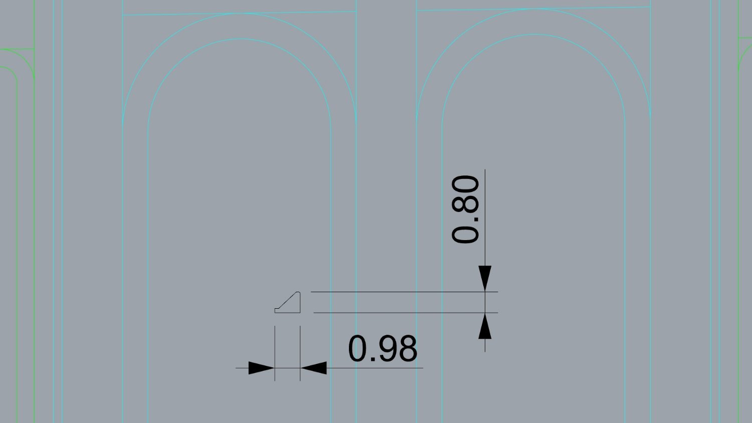
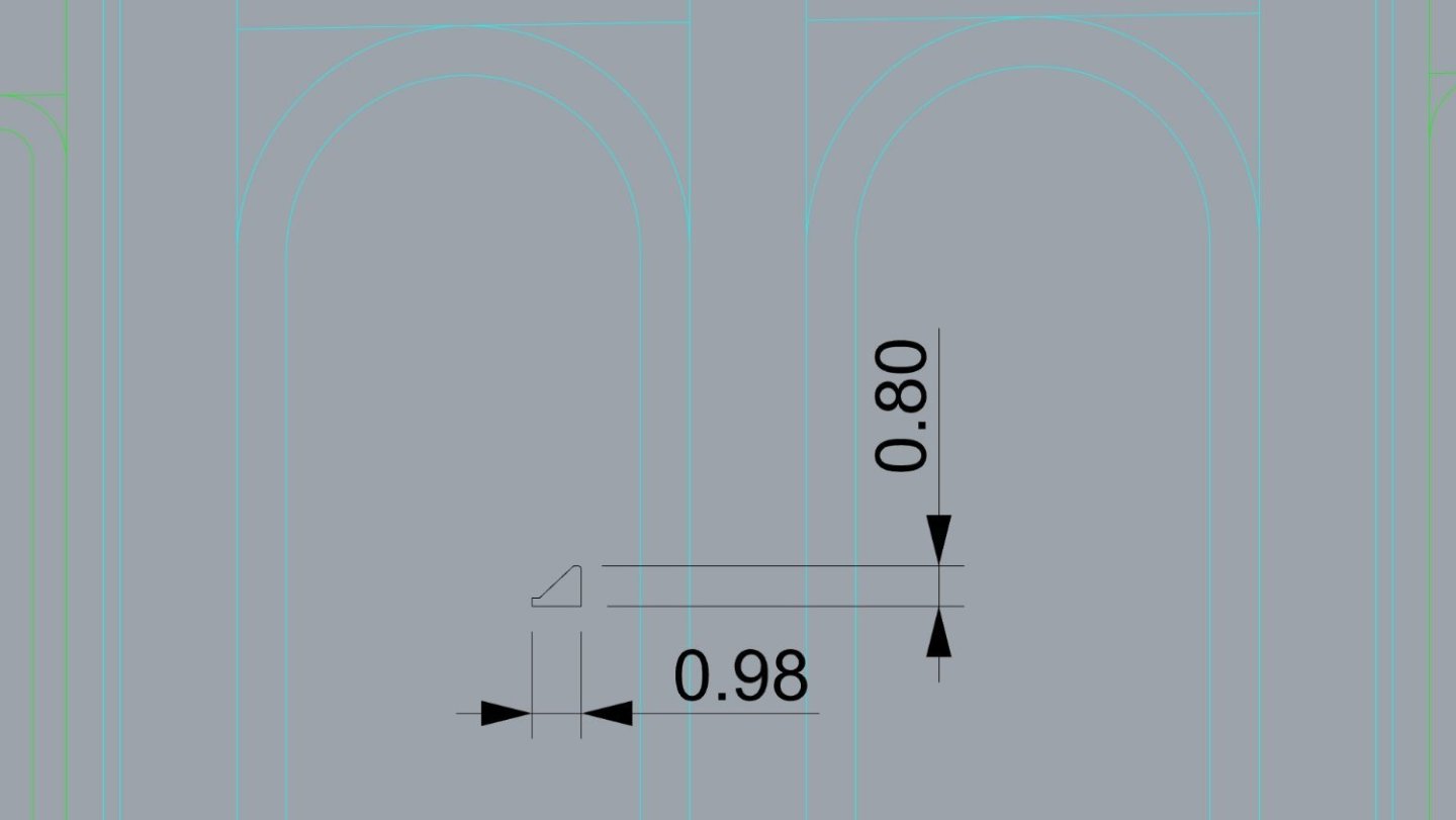
I wonder if I can form this with a dremel in a fence and run the profile on the edge of a strip before cutting it off with the very fine blade in my proxxon saw and then just wetting it and bending it into a jig until its dry and then fitting it into the panel. At this size any play in the collet will ruin the moulding. Here is the profile.
-
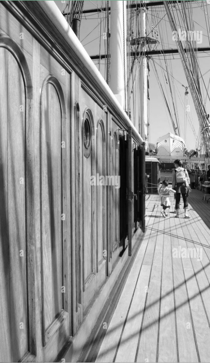
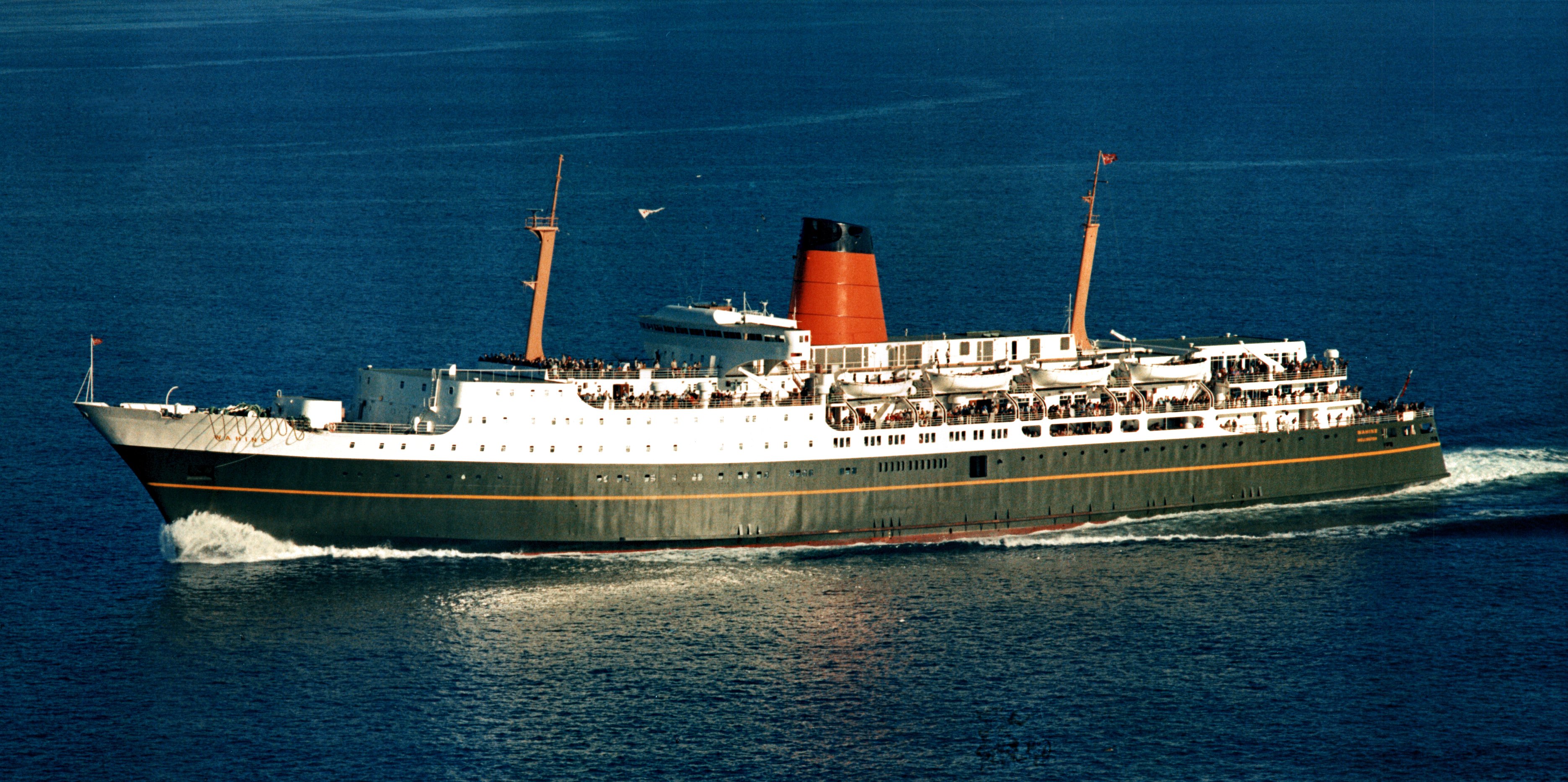
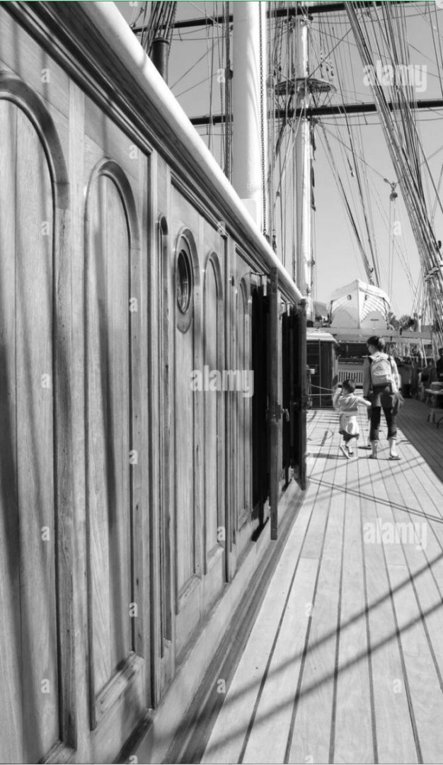
Thanks for that, I really want to make it from the same wood, as it's all varnished. Also the profile is triangular with a small lip, not half round. I doubt I will et the small lip at 1/40 but yeah adamant its got to be wood It can be seen here in this image.
-
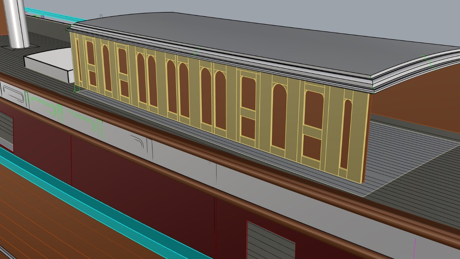
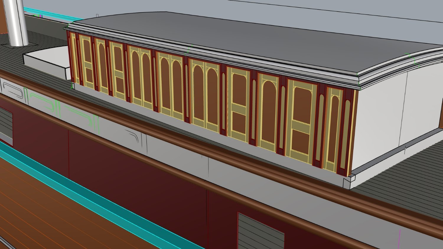
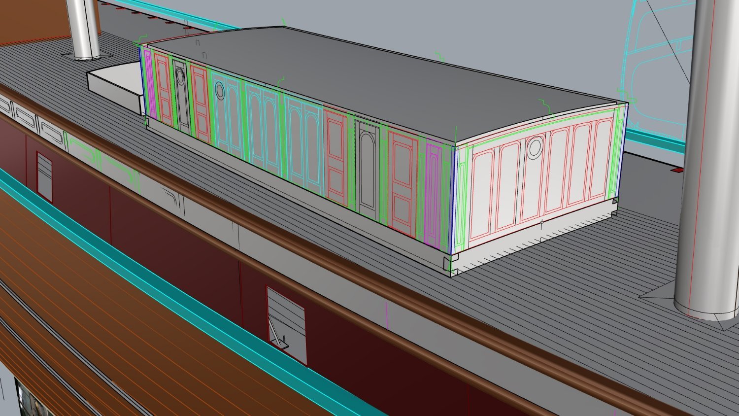
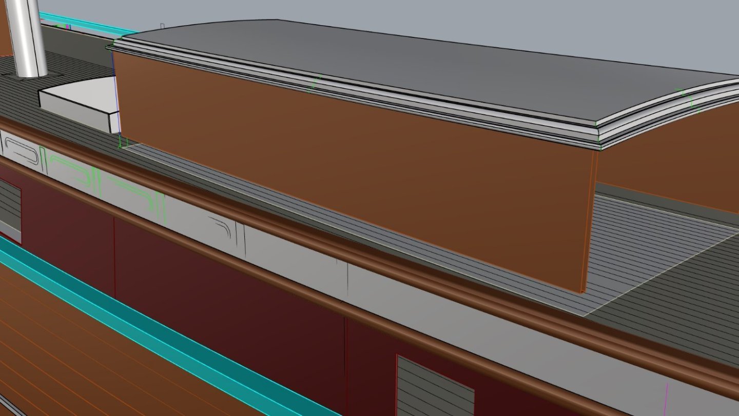
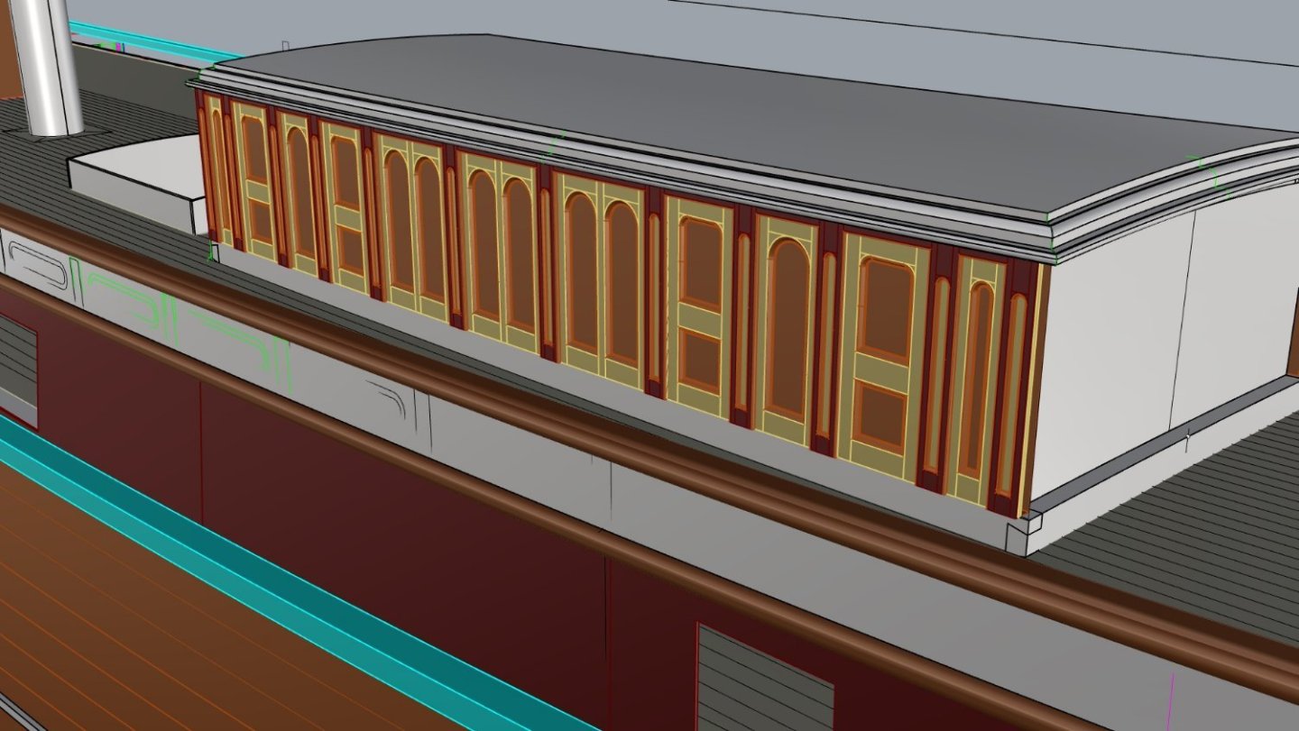
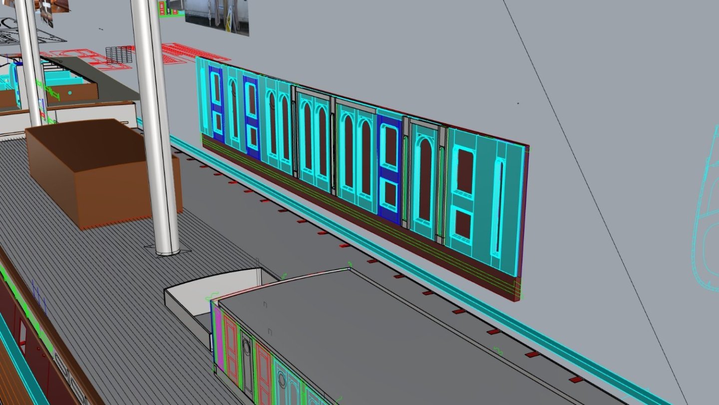
Just some shots of the last CAD jobs to do. The Monkey poop interior for those who wish to build it out, maybe even have a removable roof, all to scale. And lastly the deckhouse panelling, this is going to be a challenge, it's made in 3 layers of thin cherry, a 2mm base then the .8mm second layer and then the .6 third layer, the mouldings will be a real challenge as the main ones are just .9mm square and have a profile. If possible I would like some advice on this if anyone has any, I know abut scrapping profiles but due to the tight bends I am thinking of using strips and bending them into place with steam and water...thoughts? anyone who has done this sort of work?. Surprisingly no plans have these details as built on ship, but rather just approximations, however this is done from tracing photos and measurements and correcting perspective distortion. Below are the colours and codes for the types of panels in arrangement but yeah the light blue mouldings are .9mm wide and 1.1mm deep and triangular in section Here is how it will go together (not complete). The Dark brown is the 2mm base, then the send layer in light blue, and finally the grey outer layer all built as per the real thing. But as I said if anyone has some awesome tricks for making very small profiled mouldings please share. For the purpose of scale this deckhouse wall is 43mm high

-
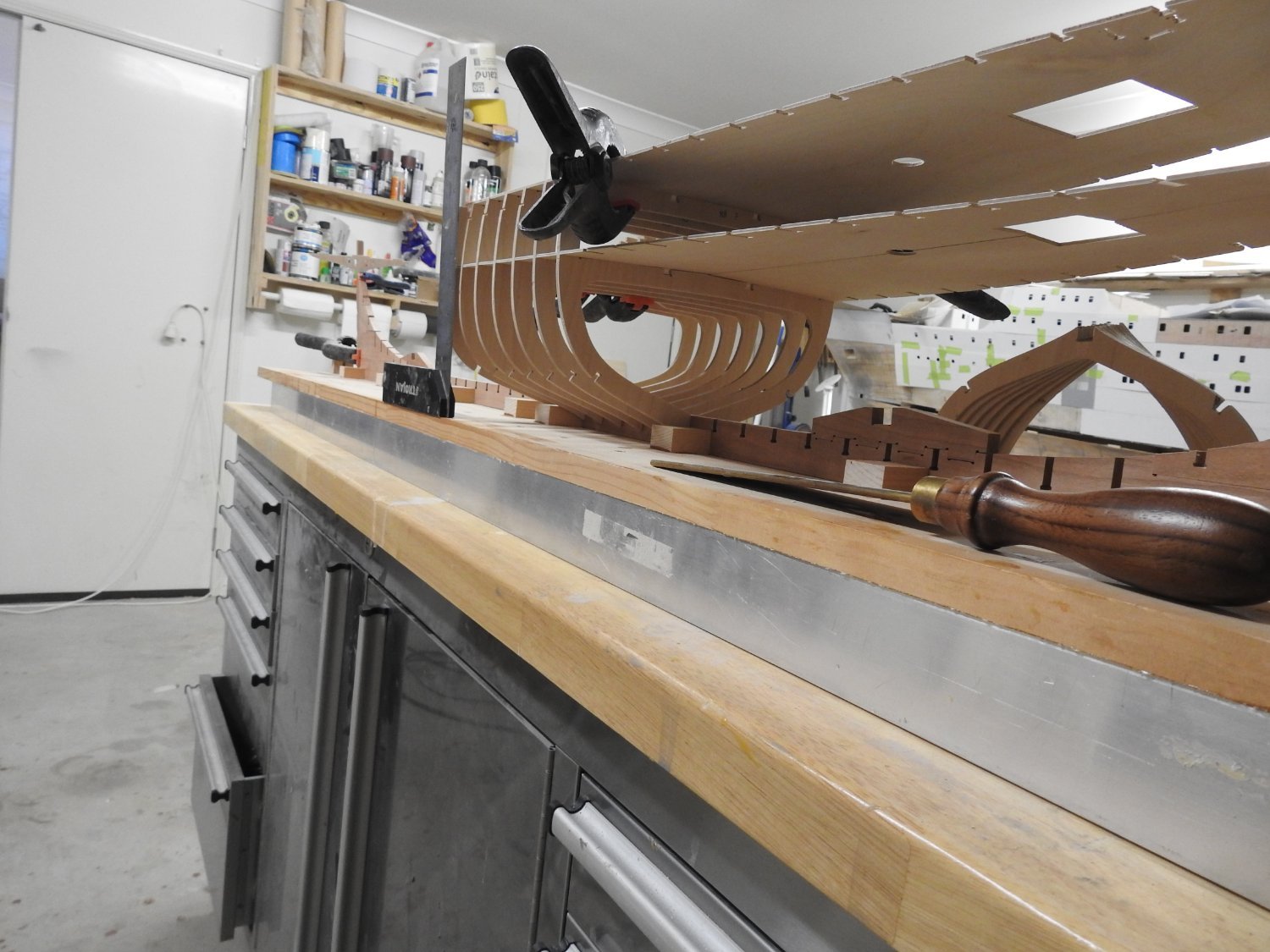
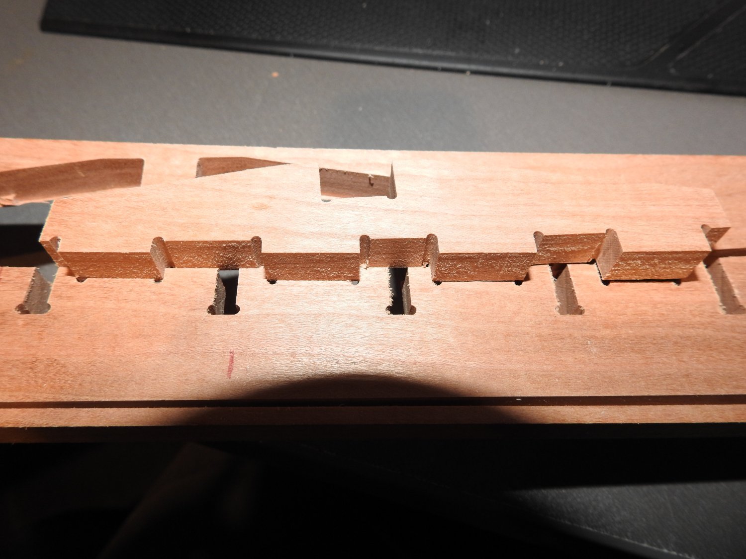
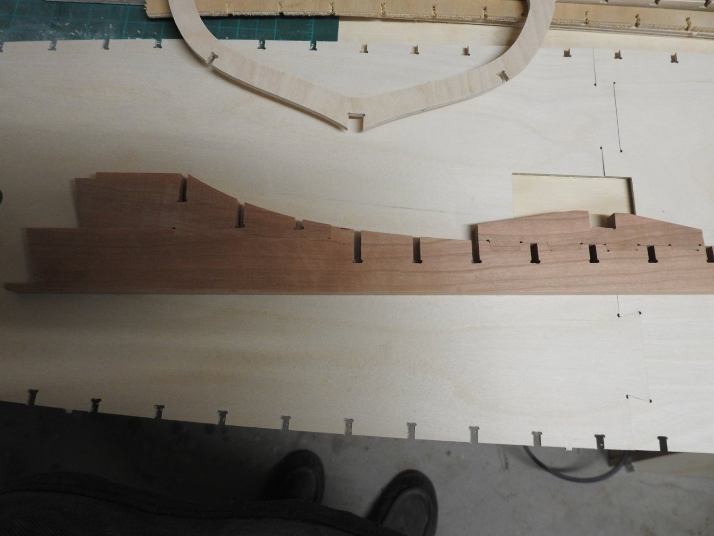
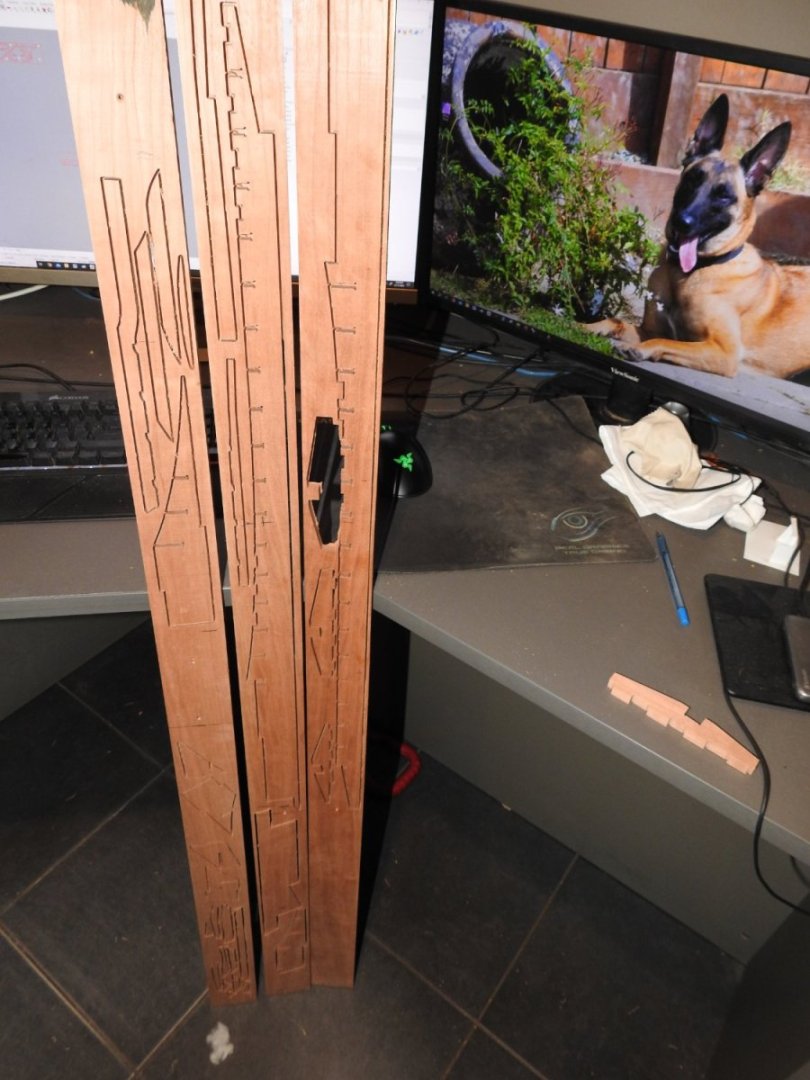
The Axial timbers. The small parts at bottom left are the cutwater. The parts to the right are the rudder parts as built. A frame The fit of the parts is shown here with the locating notches of the fore mast step, obviously its not all the way in, only the left 2 are in as the surrounding wood is in the way but you can see it lines up perfectly.


-
All the frames and Axial parts are cut , just the planking to cut and then I will take some photos, it takes me 3 whole days to cut the frames alone on the CNC and another day for the rest.