DONATION DRIVE - SUPPORT MSW - DO YOUR PART TO KEEP THIS GREAT FORUM GOING!
×


Lecrenb
-
Posts
268 -
Joined
-
Last visited
Content Type
Profiles
Forums
Gallery
Events
Everything posted by Lecrenb
-
 Interesting advice, and thanks very much for it! I have heard back from the Conservators, and their recommendation is to use a mini vacuum and brushes to carefully remove any dirt and debris from the model. After that they recommend using cotton swabs with spittle (enzymes in saliva break down dirt and do not harm wood) followed by clean swabs to dry it. That should remove any dry mold, and any work beyond that falls into the realm of restoration, not conservation. The Conservators do not recommend using any kind of solvent, cleaner, sealer, or other chemical compound on the model unless restoration is desired. They do recommend a glass case with dessicant. At this point I have sent these recommendations off to the Navy to see if we are on the same page, and to see if they want any restoration work done. Next will be putting some numbers against the work I am prepared to do, and see where they land!! Regards, Bruce
- 16 replies
-
- 1
-

-
- hull repair
- Hudson Bay Company
- (and 2 more)
-
Thanks very much for the good advice. I too was thinking vinegar or bleach, but I am going to hold off until I hopefully hear back from the conservators at the Manitoba Museum. I will also reach out for advice to the Calgary Naval Museum which is closer and where my corvette model is displayed. I have not examined the cannons close up, but at least one seems to be missing, so I will consult with the Navy as to whether or not they want replacements built. I will also post elsewhere in hopes of finding survivors of the Association that built and presented the model. Regards all! Bruce
- 16 replies
-
- 2
-
-
- hull repair
- Hudson Bay Company
- (and 2 more)
-
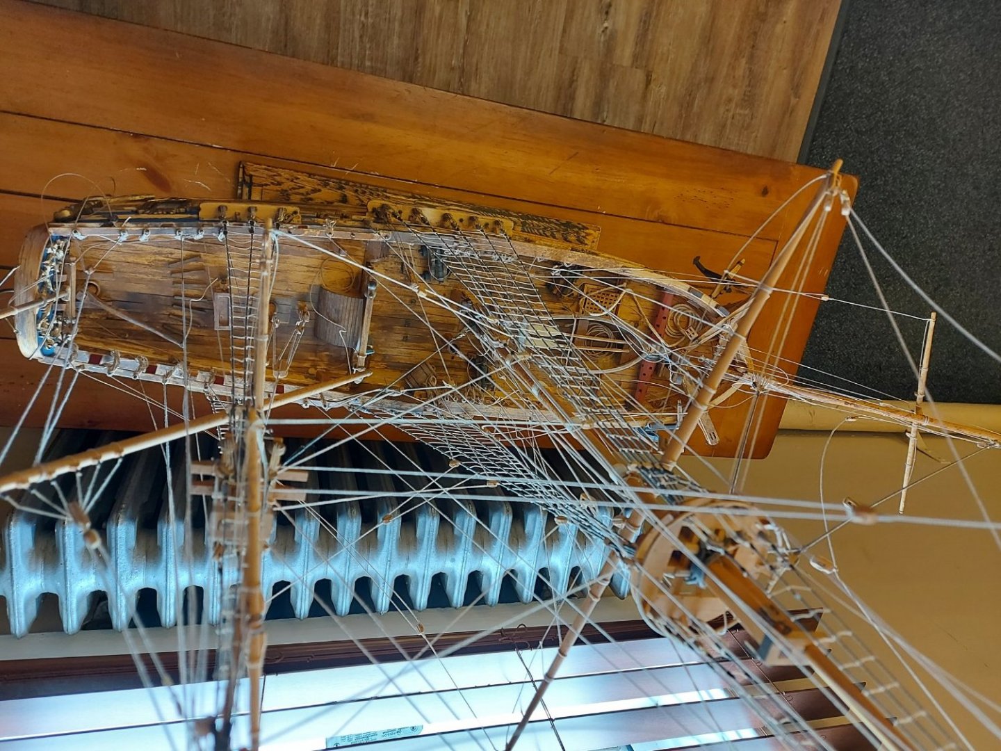
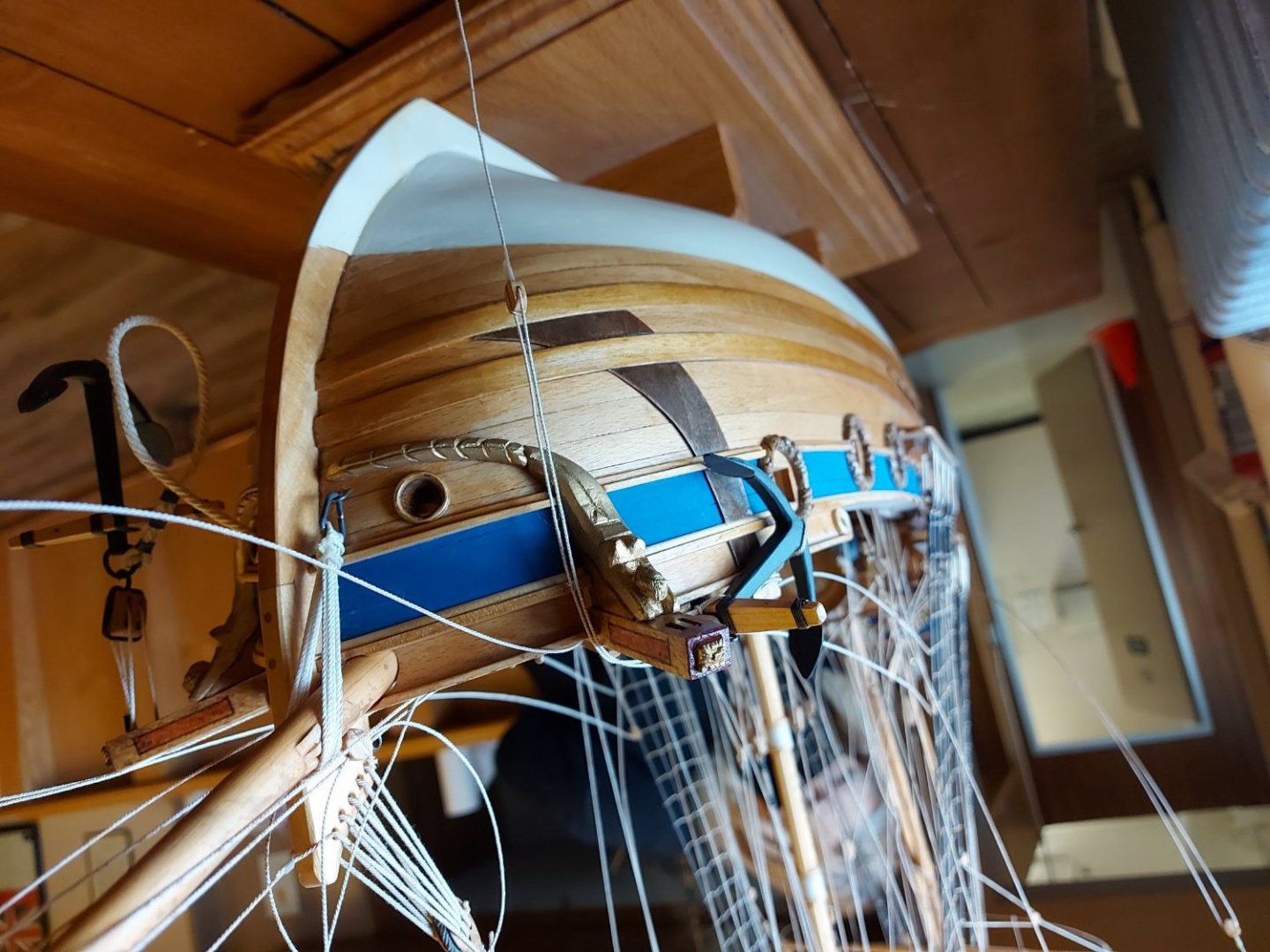
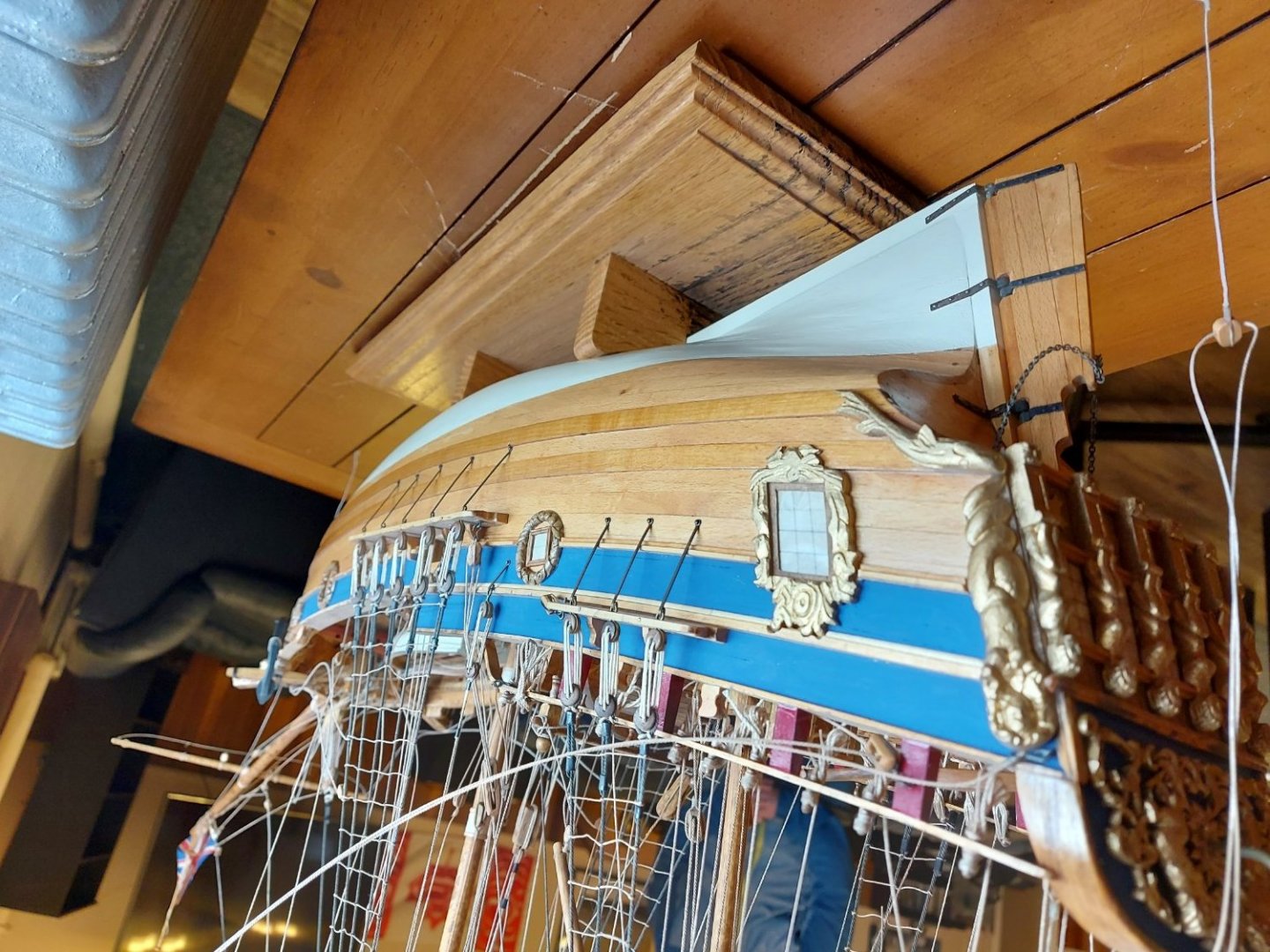
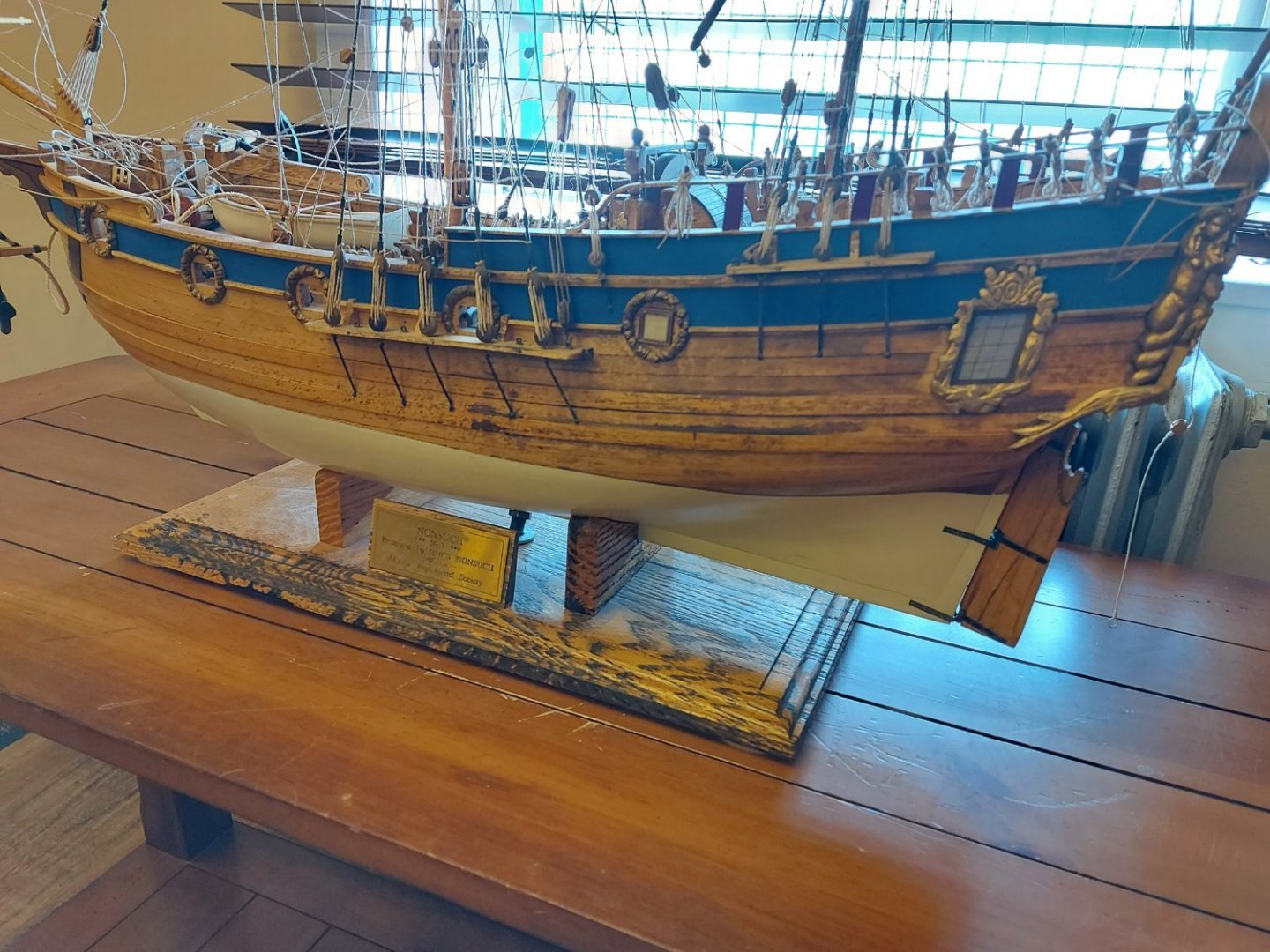
Thanks everyone for the great replies! I have in fact reached out to the Manitoba Museum in Winnipeg, who are the custodians of the 1:1 scale replica of Nonsuch, and who I believe have the plans used to build her. (She was built by J. Hinks & Son, Appledore, UK, in 1970 and sailed up and down both coasts of North America and the Great Lakes to commemorate the 300th anniversary of the Hudson Bay Company). I hope they can help with a rigging plan and general arrangement, if not close access to the replica, as well as seeking the advice of their conservators. I have no desire to try working inside the hull or removing planking, that is way outside my wheelhouse and would definitely do harm to the model. My intent is to stabilise any further deterioration and conserve it, then get it under glass. I am working on the provenance of the model, HMCS Nonsuch personnel have had it for many years and are looking through their records for information. Although the Edmonton Ship Model Society is inactive, and most of their members have passed on, I do hope to turn up at least the name of the builder. Sorry about the pictures being a bit cattywumpus, I used my phone and did not do any enhancements. Regards, Bruce
- 16 replies
-
- 3
-
-
- hull repair
- Hudson Bay Company
- (and 2 more)
-
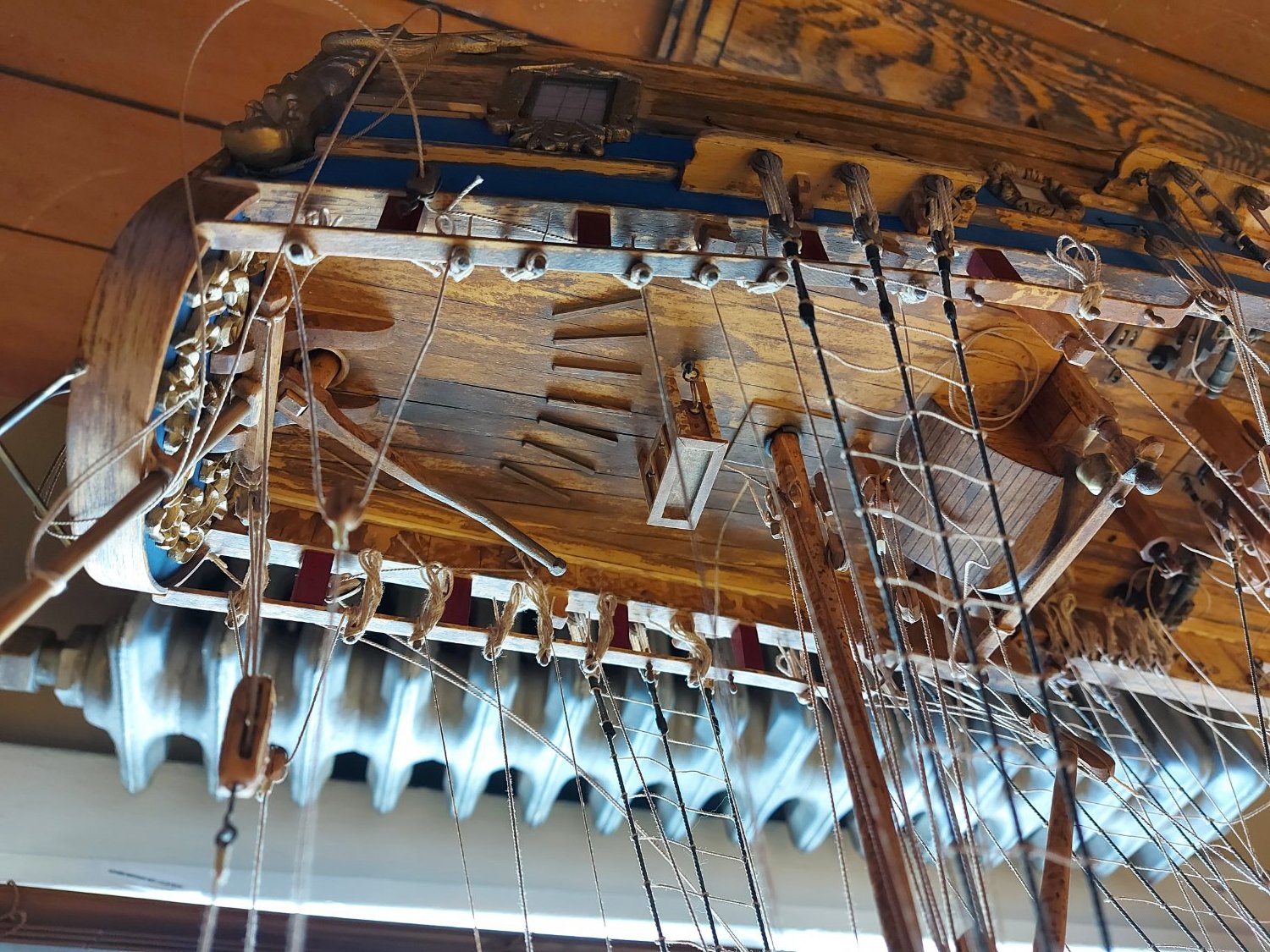
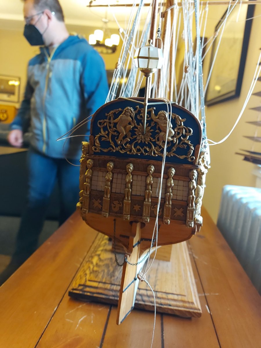
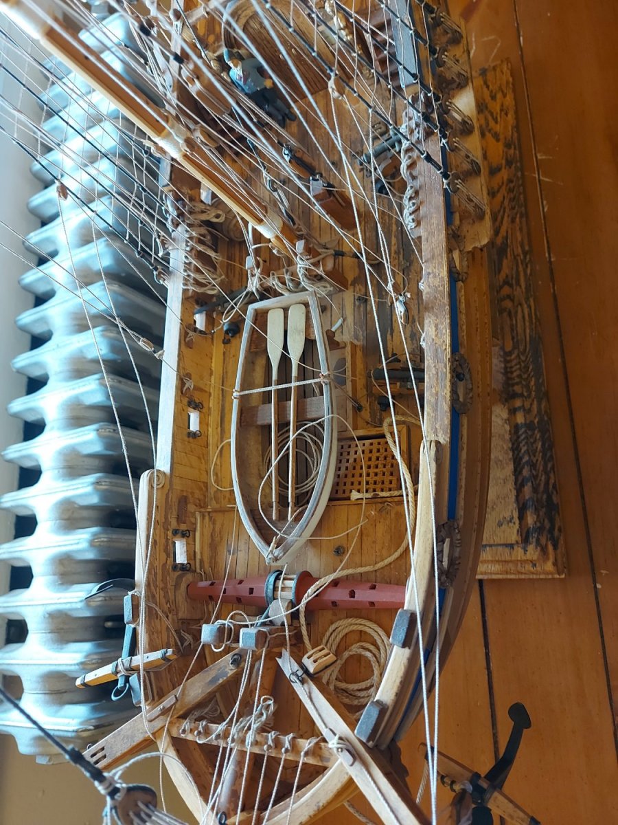
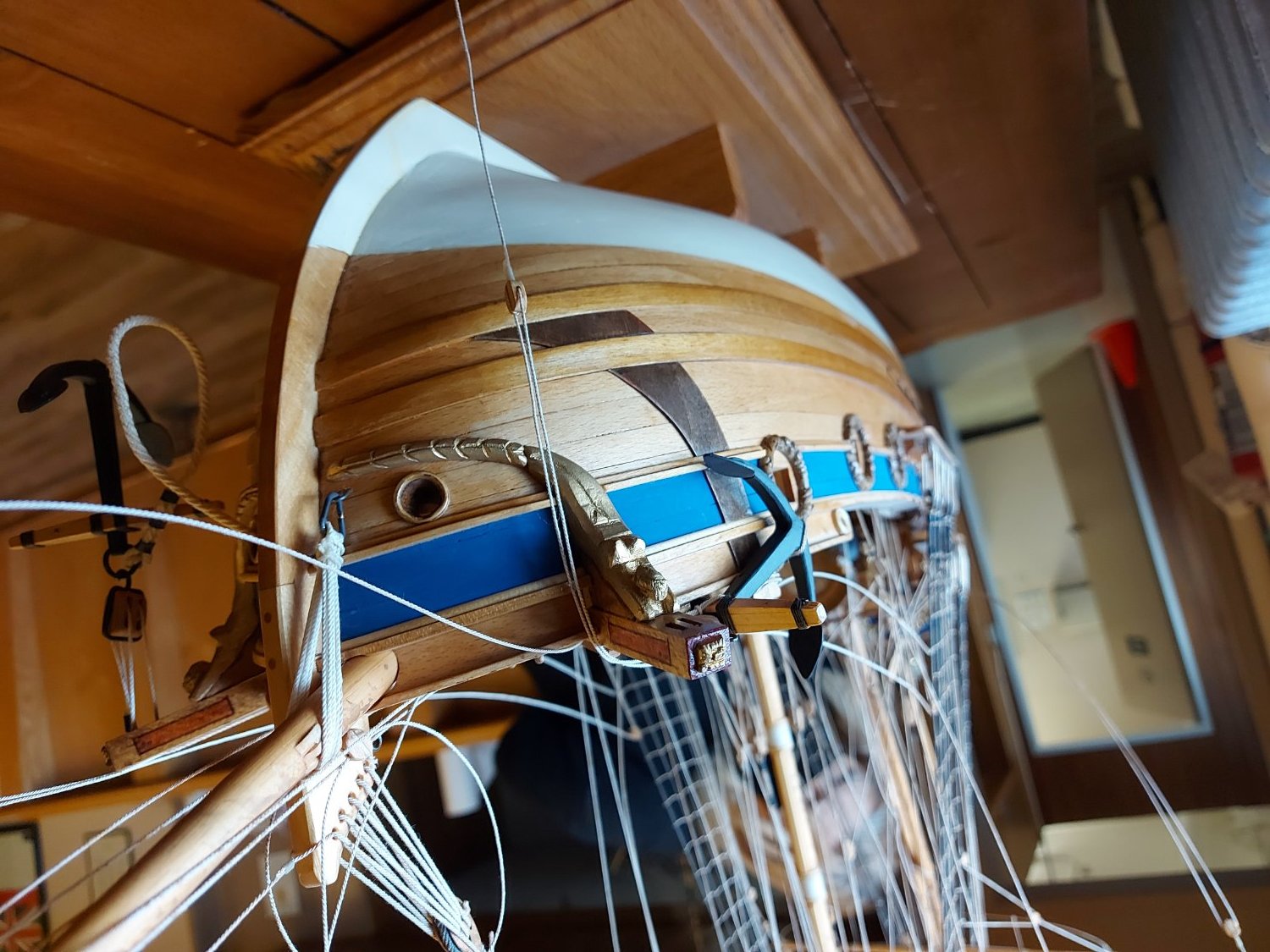
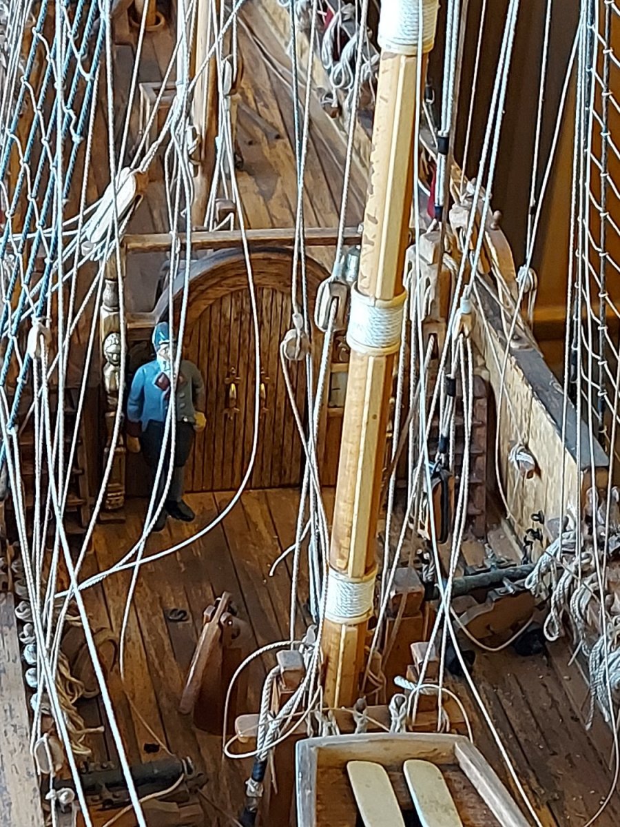
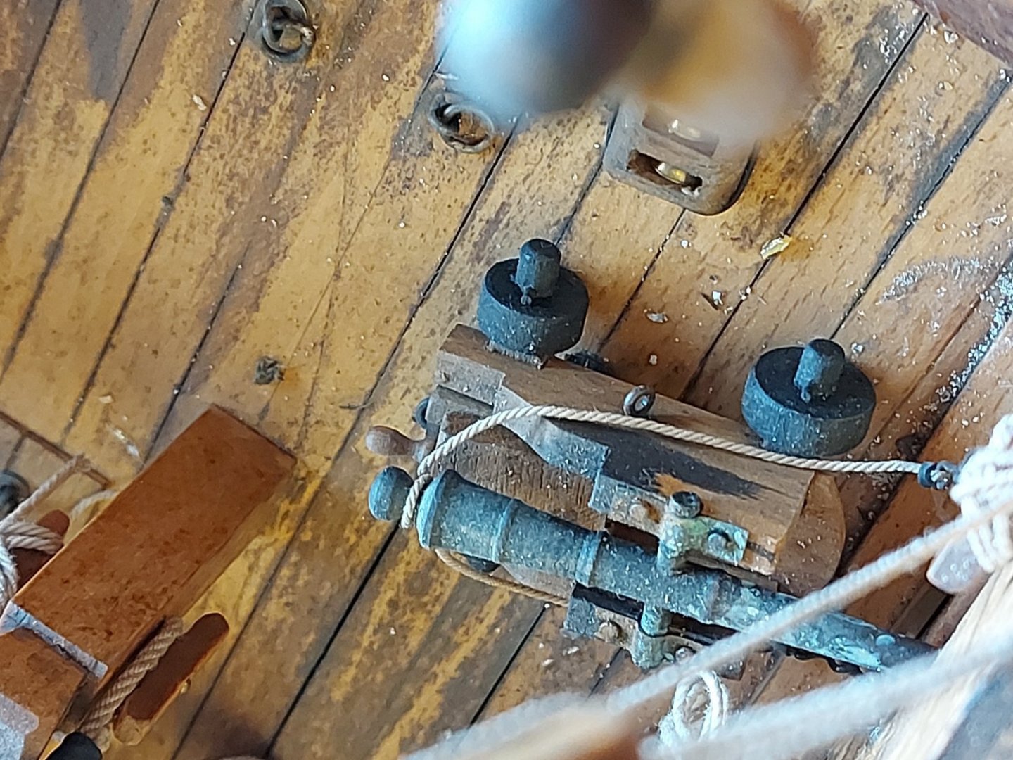
Not sure if this is the best place to ask for help with this, if there is a better one please let me know! I have been approached by personnel from the Royal Canadian Navy's stone frigate H.M.C.S. Nonsuch to remediate damage caused to their model of the Hudson Bay Company ketch of the same name. There is water damage to the hull caused when the fire sprinklers went off some years ago. There is also damage to the rigging caused, presumably, from dusting or similar cleaning attempts. The model is otherwise in good condition, and yes, I have certainly recommended a glass case! The model was scratch built by members of the Edmonton Ship Model Society many years ago, and is of excellent quality. Unfortunately this club appears to be inactive. My intent is not to fully restore the hull, as I believe doing so would cause further damage and detract from what is now part of its history. You can see from the pictures the stains on the deck and port side of the hull. The starboard side of the hull was not affected by the spray from the sprinklers. At this time I think the stains might be surface mold. The hull appears to be clear coated that has aged over time. I am seeking advice on ways to remediate the stains, at least lighten them and kill the mold, if that is what it is, or if not to actually remove it.


- 16 replies
-
- 2
-
-

-
- hull repair
- Hudson Bay Company
- (and 2 more)
-
Thanks Druxey, I appreciate the feedback! Posts will slow down for a few days while I (hopefully) get some assembly done... Wreck1919, Lofting the frame shapes created half frame patterns. Yes, I could have 'flipped' the patterns to create a full frame, but then I would have to slot both the spine and the frames. Rather than taking on the extra saw work and risk the inevitable loose fits I decided that it would be easier, for me anyway, to build up the hull using half frames. At the end of the day it was a personal decision, and I too will be interested in seeing how it works out! Thanks for your interest!
-
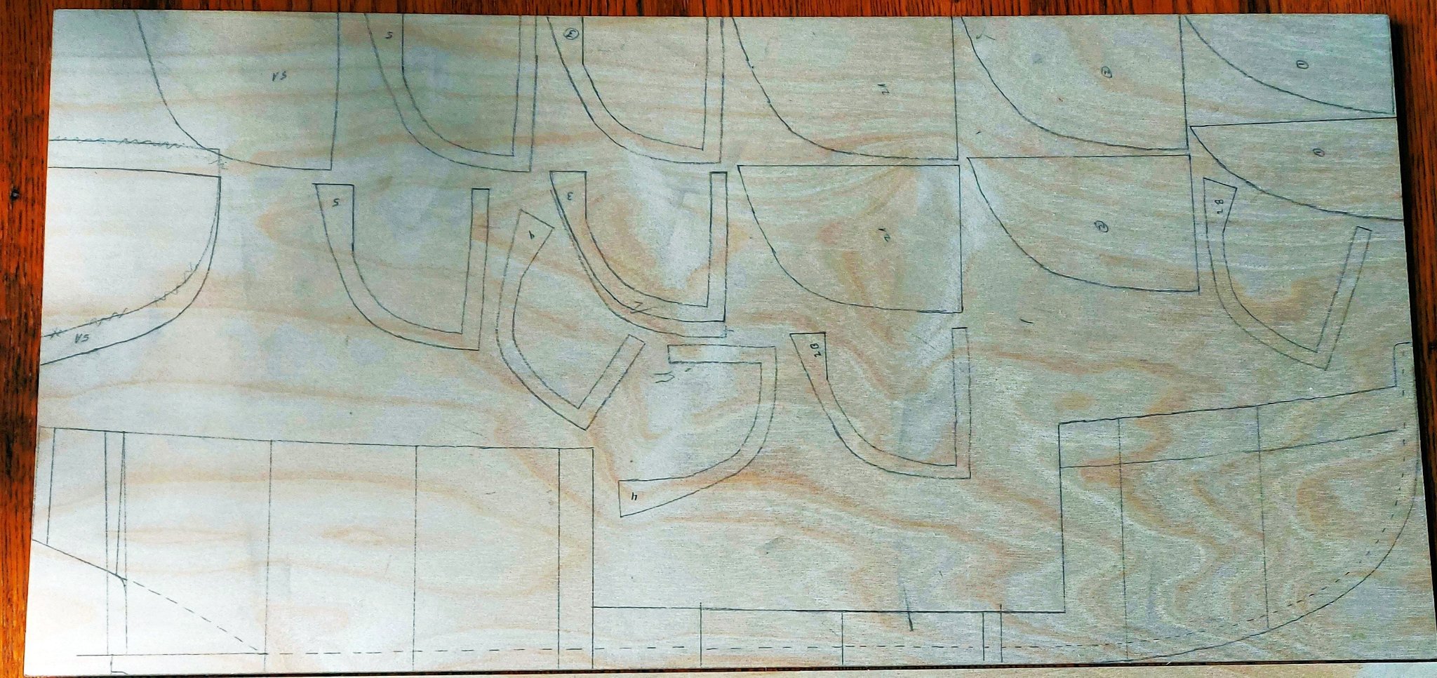
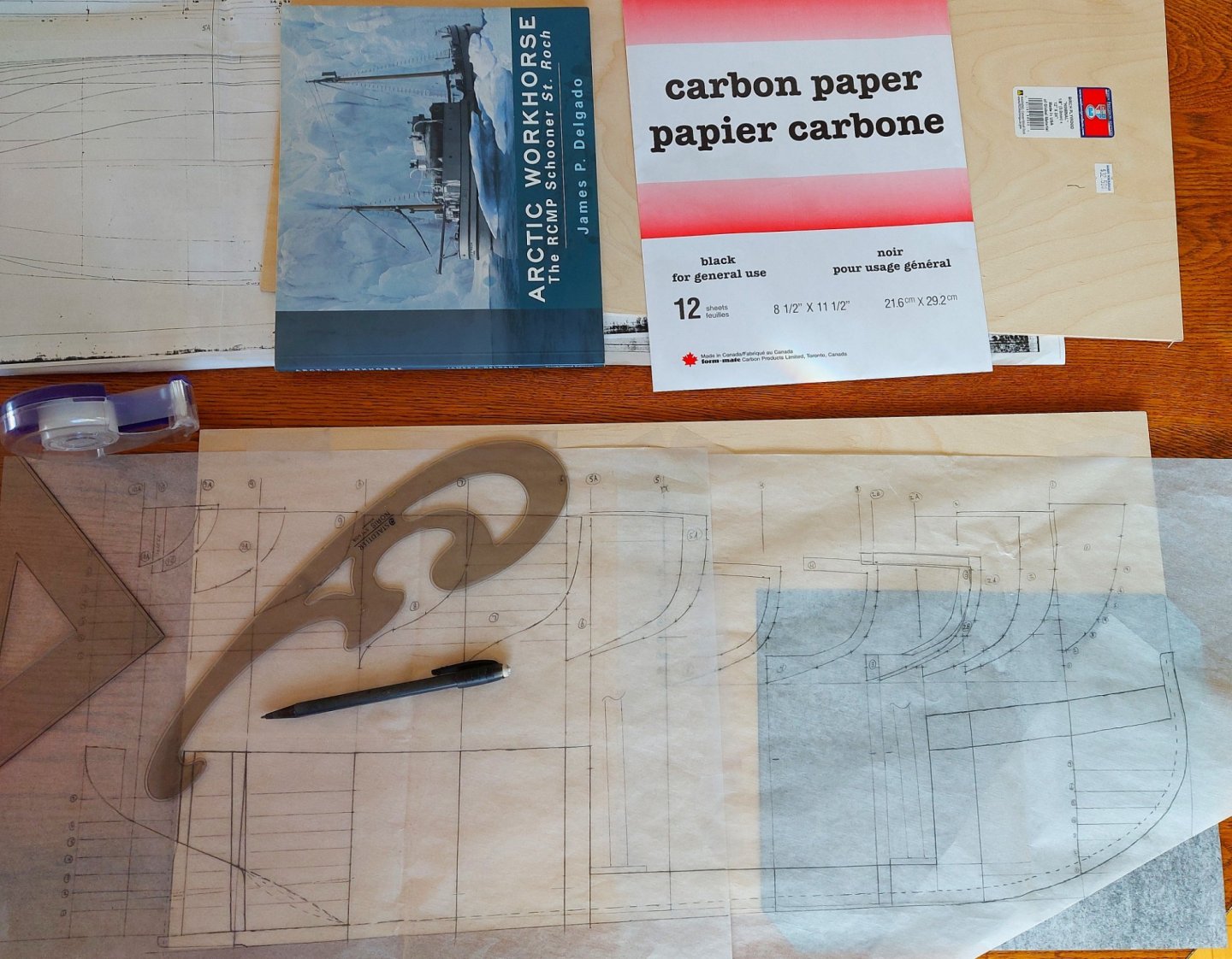
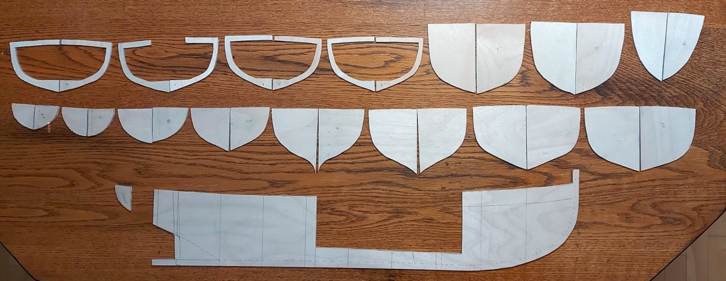
here in Alberta's capital region the wind is howling, although there is no snow on the ground yet, so it is a good day to finish the template work and get out the scroll saw! The paper templates are complete, and I selected 1/8” birch plywood for St. Roch’s hull frame. The frames are drawn half-breadth, so I will need two of each template. I could have copied each template onto separate pieces of paper, stuck them to the wood, then sawn them out; or I could have drawn each frame pair as one and cut a slot for the keel, but I decided to trace each template directly onto the plywood. The first picture shows my setup with the templates taped to the wood with carbon paper underneath. I traced the patterns with a hard (4H) pencil using my French curves as a guide. The next picture shows one of the plywood sheets ready for parts cutting, and the final one is all the frame parts after the plywood met the scroll saw. Keen eyes will see where I muffed a couple of frames and had to re-draw them. The vessel is a bit longer than the plywood, however the spine stops on the plywood at Frame 9A where the rudder well starts, so only the keel continues off the end. I will make the stern post and the keel aft of the propeller post as separate parts. There are steel reinforcing straps at these locations, so the seams will be hidden. The stern spine piece is completed as a small part aft of Frame 10A. The rudder well sides, whose shapes I will derive during assembly, will hold the pieces together.

-
Nice job Captain Shaun! Regards, Bruce
-
I am following this build with interest, not only for the excellent model work but because I am currently reading a tome called "The Arms of Krupp" about the family that commissioned and owned Germania. If anyone desires a 1:1 version of the racing yacht, Germania V is currently advertised for sale... Regards, Bruce
-
My son has an interest in German warships so I will follow this with great interest... I may get him the kit for Christmas if it is not too late! Regards, Bruce
-
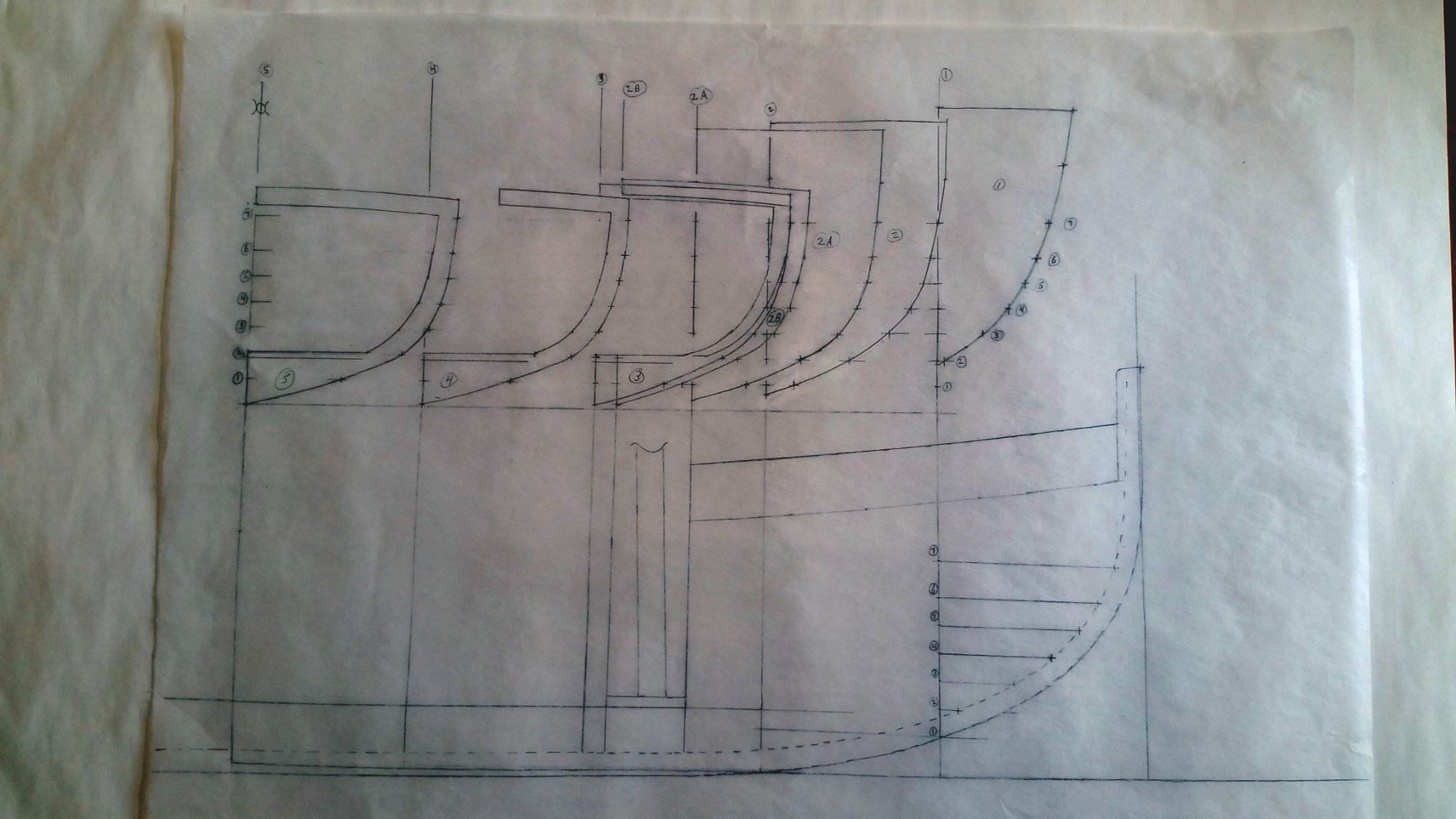
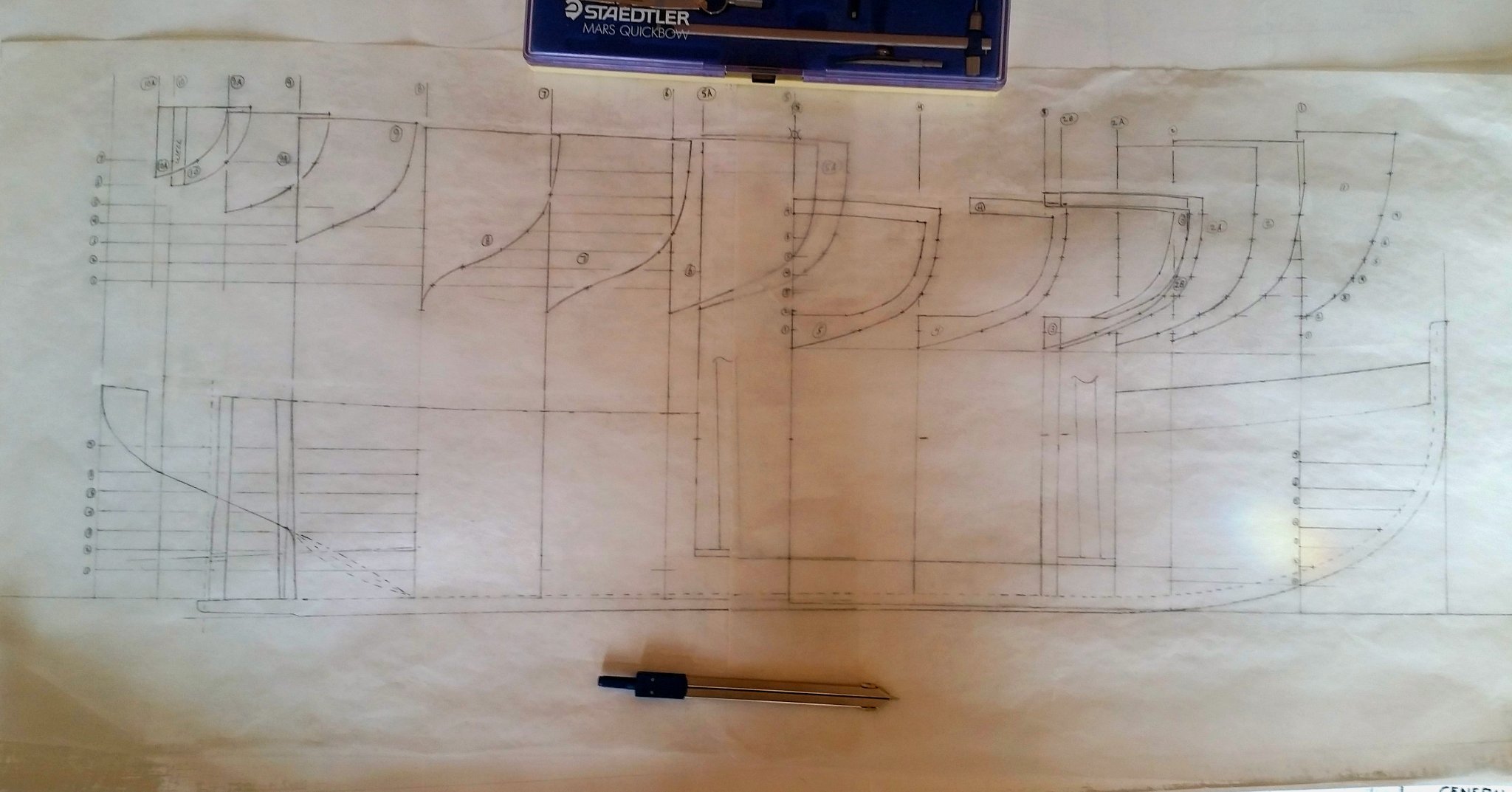
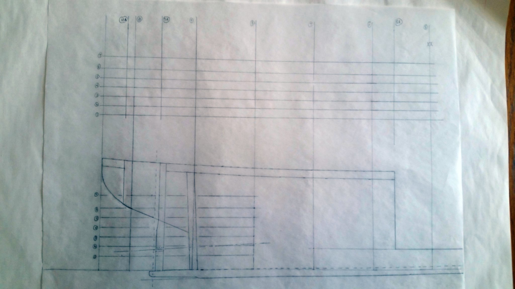
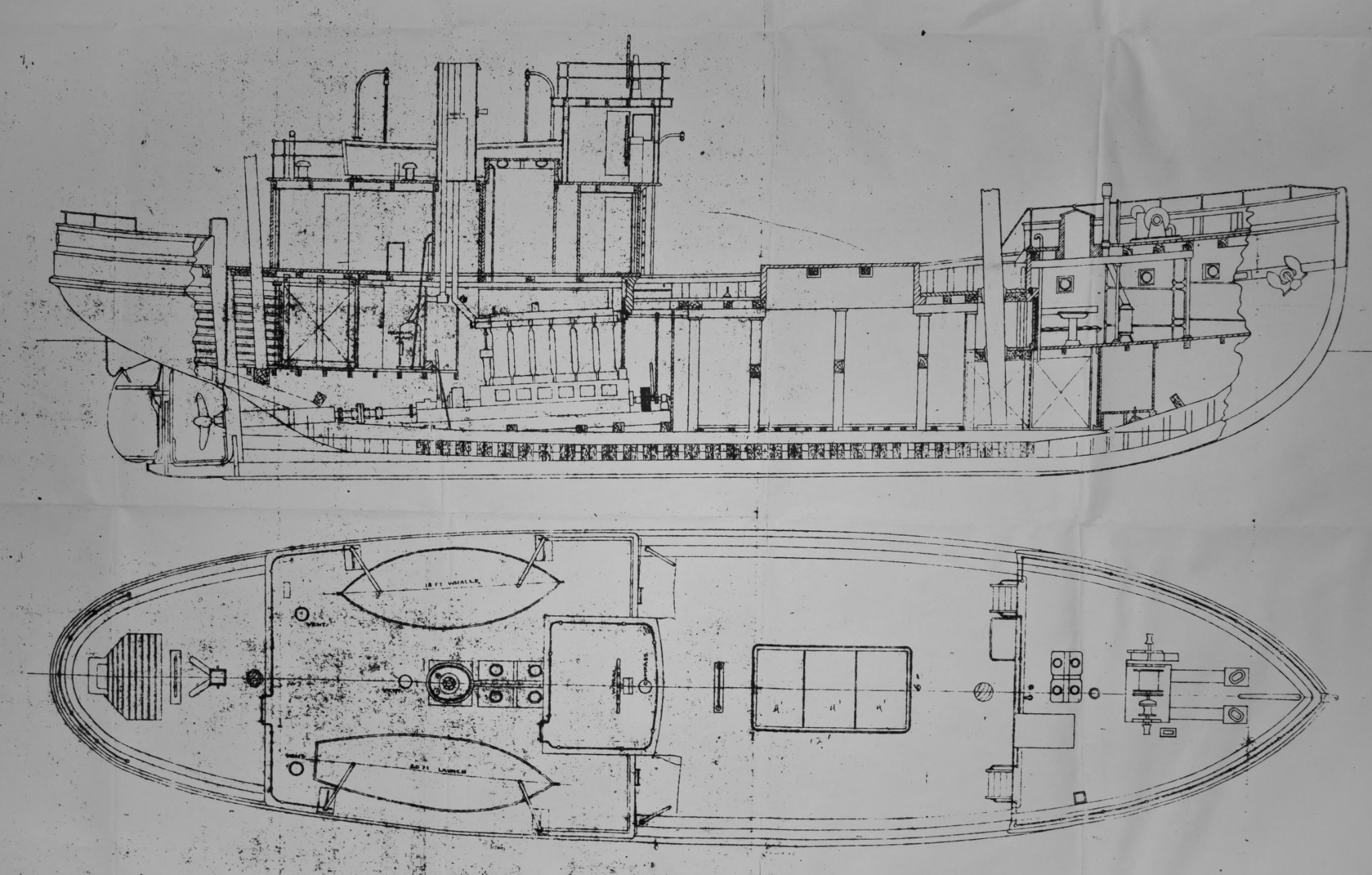
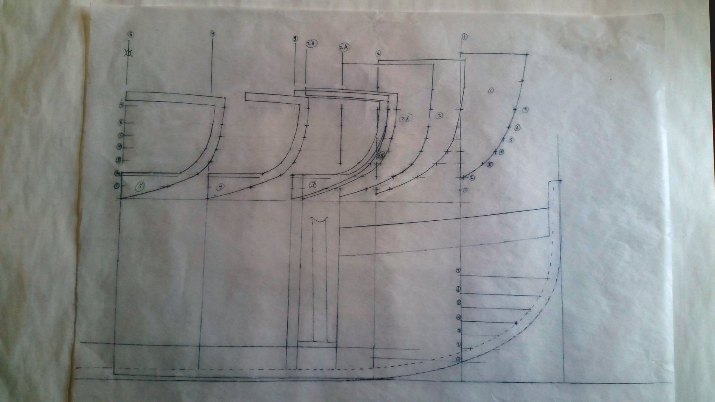
Thanks Druxey! I have now completed my paper templates... here's how: First I extended the frame locations up onto a clear area of tracing paper and drew a second set of waterlines, creating a new template aligned with the spine pattern. This can be seen in the photo on the previous post. For the aft half of the ship I will need additional frames at the aft end of the hold and fore and aft ends of the rudder well. I used my spine pattern to add these extra locations onto my new template as 5A, 9A, and 10A. The extra frame locations also need to be drawn onto the original 1927 lines drawing so their shapes can be lofted. Even though my drawing is a copy of the original I used pencil to preserve it. I used my dividers to loft the breadth of each frame at each waterline from the lines drawing onto the template, as well as the distances to keel and deck. Then I completed each pattern using French curves, including the deck camber which is given on the drawing. The first photo below shows the completed templates for the forward half of the ship. Extra frames 2A and 2B at the fo’c’s’le break and forward end of the hold are shown, as is the foremast. The frames in way of the hold are hollowed out to match the thicknesses of the hull and deck, and frame #4 is cut back where the hatch will be framed in. The frame templates nest into each other because they are aligned with the spine. This alignment lets me verify the sheer lines on my template and I think this outweighs the clutter. I did erase most of the waterlines for clarity. The next picture shows the fore and aft templates together, and the mainmast has been added. Note that the fore and aft frame waterlines were drawn different distances above the spine pattern, something I would correct if I use this method again. Keen eyes will note an extra line on frame #10, this frame will be cut back to create the rudder well. The mainmast was removed in 1944 when St. Roch’s rig was changed to a ketch, so the museum plans I have do not show it. James Delgado’s book includes a copy of the 1928 hull profile drawing that shows the mainmast. This is too small for accurate scaling, but the hull frames are shown, and their dimensions and spacing are known measurements. I counted the number of frames and spaces between the masts and transferred that dimension onto my spine template. The result matches my historic photos, and I am confident I am within 3 scale inches (1/16”) of where the mast should be. Now I am ready to transfer my patterns onto plywood and cut them out!

-
I'm not laughing, I think you have built a credible model of St. Roch. I have visited and photographed the ship in the museum and have now started a scratch build of her. BTW, the original ship's outer layer of planking is Australian Ironbark, chosen for ice protection, and was deliberately uncaulked to allow seawater to penetrate to the inner planking to help prevent dry rot. Hence the gaps. Well done sir! Regards, Bruce
- 9 replies
-
- 1
-
-
- st roch
- billing boats
- (and 1 more)
-
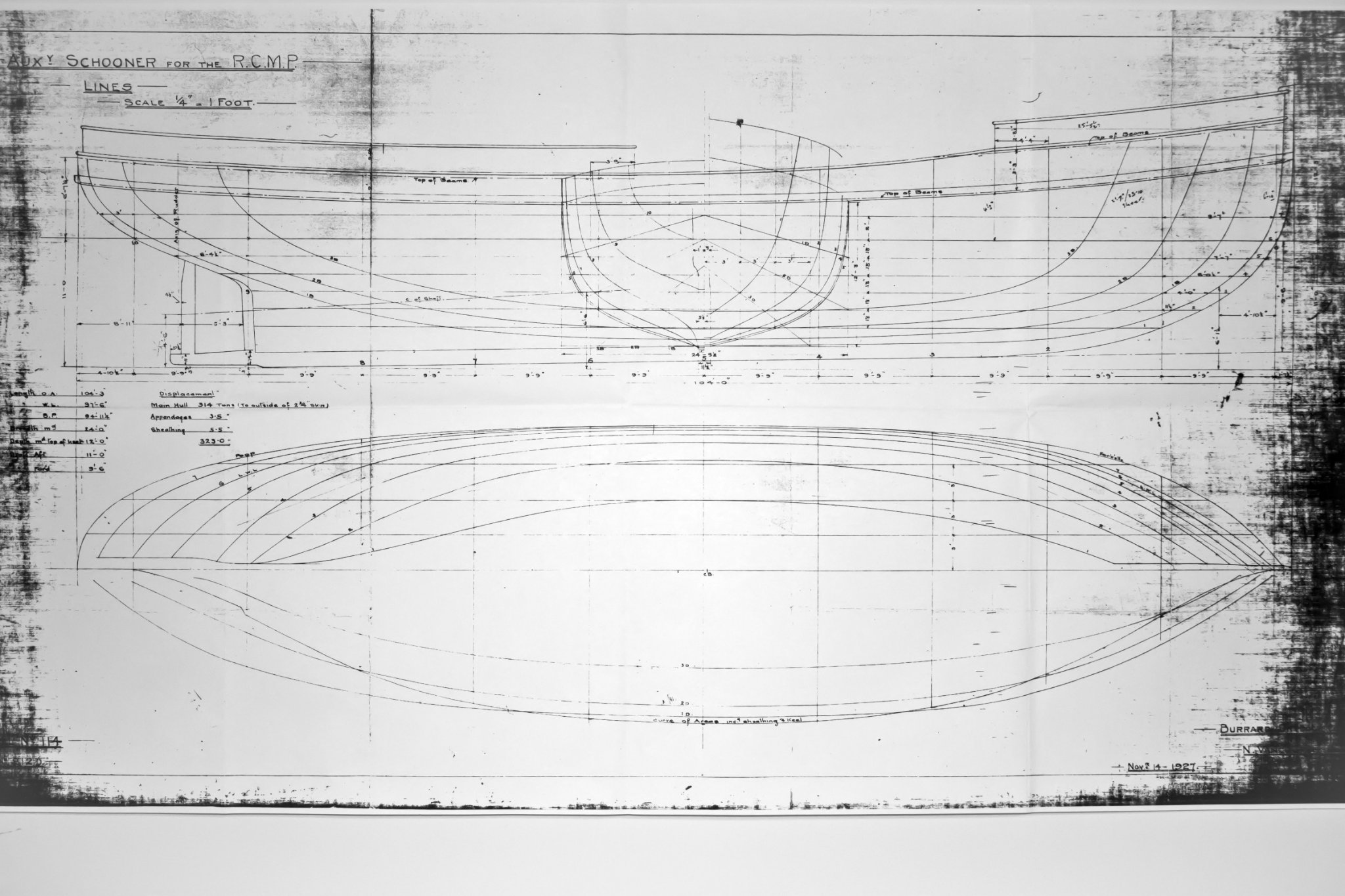
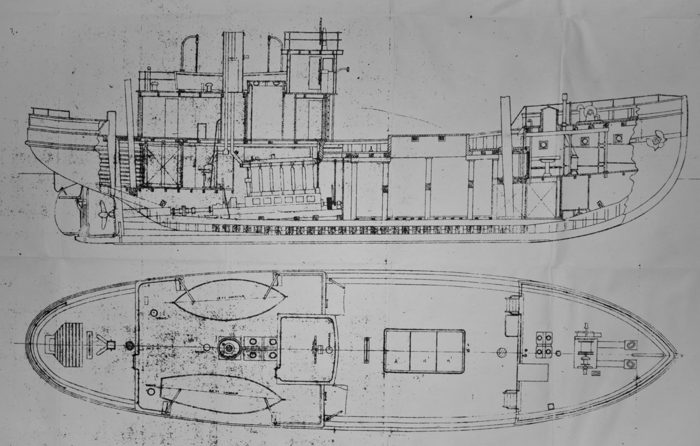
Hi all, first post here so please be gentle. I am building RCMP St. Roch as she spent most of her life in the Arctic, wearing her mainmast and schooner rig and with the original smaller deck house. I am using copies of original plans from the Vancouver Maritime Museum where the ship is currently the main exhibit. I am also old school, so dividers and French curves are substituting for CAD! The only kit of St. Roch is a 1:72 rendition by Billing Boats which I see several members here have built or are in the process of building. I look forward to checking these builds out! I will build my model plank on bulkhead in 1:48 scale, with the cargo hatch open to show the transverse beams in the hold that were designed to prevent the hull from being crushed in the ice. I will also include the rudder well which allowed the rudder to be lifted clear of ice. I will decide how to display the sails later in the build. So, to start: I drew patterns onto tracing paper to be transferred to plywood for cutting out. My copy of the 1927 lines drawing is 9 scale inches (3/16”) short, so I did not directly trace parts from it. I also referenced a copy of the 1944 section and general arrangement plans, but with caution since it shows her later configuration. I drew a base line onto the tracing paper, then vertical lines to mark the frame locations shown on the drawing, and the stern. Next I added seven horizontal waterlines, also from the lines drawing. Their vertical distance from the base line is not important. The spacing of frames and waterlines came from actual measurements noted on the lines drawing, which when transferred to my tracing paper made up for my undersized copy. When checked, I verified that my hull will indeed be the correct scale size after planking. I now have a template onto which I can draw my model’s spine. I used a 1:48 scale rule, dividers, and French curves to transfer scaled measurements and known dimensions from the drawings to complete this pattern, which is the aft half of the vessel, drawn from frame 5 aft to the stern. I will need extra frames at the aft end of the hold and the fore and aft ends of the open rudder well, and these locations are shown on the 1944 drawing, taking note that a jog was made in the hold to enclose St. Roch's larger engine. I transferred these locations to my spine drawing then drew in the propeller and rudder posts and the rudder well, and indicated the rudder axis and propeller shaft centerline. The large jog near frame 6 is the aft end and floor of the hold. Next I will finish my paper templates and cut wood! Thanks for looking in and comments and critiques are welcome!


- 378 replies
-
- 11
-