


Jaager
-
Posts
3,084 -
Joined
-
Last visited
Content Type
Profiles
Forums
Gallery
Events
Everything posted by Jaager
-
 Congrats, citrus is supposed to be excellent for our uses. It is just darn near impossible to obtain if you do not live in a subtropic region. The method that I use now for framing has a need for 2 inch thick stock if building a 3rd rate or larger at 1:60 or larger is a project. Otherwise, 1 inch is just the ticket and should be treated as Jim has advised. In addition coating the cut ends (including cut off branches) with a thick coat of latex paint if you have any left over from house painting, or varnish or coat with melted paraffin. The point is to slow the rate of water loss to something close to or less than the rate from the side surface. In most species of trees this reduced checking and splitting. Once you have the billets, you can use the bandsaw to freehand shave off the bark. This speeds water loss or at least equalizes the rate at that surface and removes any bark beetle infestation. If you do not have use of a bandsaw, a draw knife is a quick way to shave off the bark. Other edge tools work, it just takes more work.
 -
Questions about double wale
Jaager replied to Erik W's topic in Building, Framing, Planking and plating a ships hull and deck
A function of wales = to provide additional strength to counter the weakness caused by gun ports? There may have been a change in gun weight and/or force produced by the powder charge that was a reason for the addition of another thick strake. Also the ledge produced by the thin strake above the lower wale would be an entry point for water into the hull that filling in the gape would remove. Perhaps they got tried of doing the extra work maintaining that caulking. -
Russ, I got that one too. It does not need to meet much resistance before it stops. I tried a " 3-12V, 2A Selectable Output Supply " Found one for $15 at Marlin P Jones - and it seemed to work better with more juice - so the problem may be the power supply. I can't be sure because I need to get parts to make the connection. The power supply wants banana plugs - which end with alligator clamps or bare wire and the tool wants a plug like computer external HD DC power supplies use. I am waiting for Jones to restock some other parts before I order. Maybe more Volts will burn out the motor but it is that or nothing.
-
To answer your first question: no. A plank bender is not essential. The type that you may be looking at is a soldering iron with a specialized attachment with a French curve type surface. There are several ways to bend planking and that tool may not be all that good a choice. There are several threads here on the topic that you might review. At the least, Harbor Freight has a low end resistance iron for $4 if you want to try a dry heat method. For hull mounting clamps, there are vac base and screw clamp swivel vises of various sizes and prices.- an electronic catalog has one for $13 and will multitask more than a dedicated tool.
-
This outline may well be a novel, but this is how I organize the progression of framing. It is a progression over a long time period, but the introduction of trade with the East added a profit factor and an incentive to develop larger and faster vessels. I will start with the Dutch about 1600. As per Hoving, the hull started with the keel, stem, and stern post and with or without a few intermittent molds - the bottom planking came first and the timbers - floors and futtocks were then added. The design was tradition based and followed "rules". The timbers were a bit irregular in length and probably width. As late as 1669 the framing that Dik shows for the 7P has the floor and its follow on timbers as a continuous unit to the rail. The first futtock half laps it and starts well up from the keel. The English probably wanted a more scientific or at least more predictable method. Whole molding was the method to develop the molds mounted on the keel - there were probably more of them than the Dutch used and ribbands (rib bands) were fixed to the molds to define the shape. The floors and futtocks were cut to fit inside the ribbands and then the planks were fitted. The timbers were probably not artful to look at and the first futtock started well above the keel and scarped (sided jointed) to a floor and second futtock. I suspect that there an air gap on the other side - with or without clamps in the gap. The models have continuous joins and the timber lengths were regular. This looks better and is easier to do. Fox describes evidence that the open spaces were cut from what was essentially a solid hull. The points I see are about 1670 the models have Admiralty style framing. By 1719 the models have free standing paired frames with or without continuous butting filler frames. I imagine it was a time of generational conflict and tradition vs. "modern". At the end of the 17th C. the first futtocks probably progressed to the keel and the air gaps became narrower and vertically continuous. The paired alternate futtock full frame became favored. The hull shapes outgrew the limits of whole molding and the timbers were shaped on the ground using portable molds rather than a mold mounted on the keel. What was probably a confusion of methods was probably ended with the Establishment of 1719.
-
If the water content of the wood was higher than equilibrium level during assembly, then the shrinkage should be one way. A fix now should hold. If the wood was at equilibrium during assembly and its environment has changed enough to open the seams, I would worry that a reverse change would cause a swelling effect. If a repair that filled the cracks was made using a hard material, then a swing to swelling would lead to a buckling stress. If the fastening is strong enough to resist the hydrostatic pressure then all should hold and the water molecules would be kept out, rather than the wood move. If the water pressure force is the stronger one, then the planks would probably pop up.
- 19 replies
-
- 1
-

-
- separation
- wood movement
- (and 1 more)
-
When to varnish
Jaager replied to medic's topic in Painting, finishing and weathering products and techniques
As a true plastic, I am thinking that it would be the least effective surface to use PVA on. I do not use CA, and since (as I understand it) CA has poor shear force resistance to begin with, it is not likely to be a good choice there either. I have used poly on a kitchen floor and on paneling and bookcases, but when attempting to emulate the old craftsmen and artists of the 17th C. and 18th C., poly does not appeal to me for use on a wooden model. -
When to varnish
Jaager replied to medic's topic in Painting, finishing and weathering products and techniques
Most varnish products will probably not play nice with most glues. The glue will "bond" to the finish rather than the wood. With no pores there is no penetration so any bonding will be electrostatic rather than mechanical. Traditional varnish is boiled linseed oil "cooked" with shellac - organic solvents. These days polyurethane seems to be more popular and there are water based varieties. It is a synthetic plastic. If you are doing an upscale modern yacht, varnished decks may be appropriate. You wear no scuff deck shoes to walk on them. For most other classes of wooden ships, a slick varnished deck would be really dangerous for the crew. Because of scale effect, a flat or egg shell finish even for high gloss prototypes - or at most matte.. You might consider super blonde shellac at half strength ( 5%) * and rub it down with 0000 steel wool or a Scotch Brite pad. In any case, if you intend to apply a finish before adding and gluing down additional components - it would be wise to occlude the glue sites with painters tape or masking tape. * orange shellac is full strength at 20 lb cut ( ~ 20% solution in methanol, ethanol (denatured) or ( Pharmco grain - 95% - if you do not mind paying the taxes), or anhydrous isopropyl. It will darken the wood. super blonde shellac is a very light amber. The purification process removes components that help solubilize it - so - full strength is 10 lb cut ( ~10%). Primer or 1st coat = 5%. There is a bit clearer grade: plantina shellac flakes - but it is not that lighter and costs about twice what super blonde costs. -
There are also draw tongs. They are for gripping wire, but work with bamboo - if pieces of sandpaper are used as an interface to grip and you do not squeeze too hard.

-
It may not be a significant level of energy with LED lighting or florescent either, but the way greenhouse effect works is that some visible energy photons will degrade to IR when they strike something inside the chamber and the transparent material at visible will reflect IR and keep it inside. Granted, most will stay in the visible spectrum and reflect back out. - We would be able to see what was inside otherwise. - But while a UV filter may protect against the chemical reactions that UV produces, I doubt that it would negate a heat build up in an efficiently sealed chamber. With your room lighting, the lack of heat with LED even given your high light level, shows just how inefficient and IR heavy incandescent lighting is. However, given where you live, there may be parts of the year where you might miss having a little extra IR. When I was using 300 W of bulbs to heat a homemade kiln 24/7, I did have a measurable increase in my electric bill. Our philosophy seems to be in tune, I also have a tendency to over engineer my designs.
-
I have thought about the same ideas. For the gas to remain, the container would have to be air tight. The walls are transparent, so light can enter. Being totally sealed, there is a possibility of an extreme greenhouse effect and the container becoming oven-like. There is a problem with this - even in a not totally air tight situation. Joel has it correct - vent holes for circulation for both temp and removal of outgassed compounds. PVA wood glue would probably release acetic acid. My thinking is vent openings at the top ( for temp ) and probably also bottom for circulation. The trick would be to keep dust out. Too dry - the wood may check and split over time. .The museum standards for ship models are probably intended to preserve a model for as long as is practical - by using materials that last to begin with.
-
Making Rope
Jaager replied to ca.shipwright's topic in Rope Making/Ropewalks's Discussions about Rope Making
The linen supplier twists up the fibers into yarn. This is sold as LEA - which is essentially an obsolete measurement - it has been replaced - but I have not mentally absorbed it. Since I have obtained about as much and as wide a variety of linen yarn as is obtainable now, I don't need to deal with the change. And yes, with LEA - the larger the number - the smaller the yarn. From our perspective the hope would be that 70.2 LEA yarn would be 2 lines with a final size of 70, but alas - what it means is Two 70 LEA yarns twisted together and sold as a loosely twisted thread.. If unraveled it would be two 70 LEA yarns - not two 140 LEA - which would be nice for us except - twisting up the 62 LEA is difficult - it breaks easily - so that may be the practical limit. I finally got why the old guys favored linen - the linen wrapping on Egyptian mummies is still largely intact. It does not readily oxidize. -
Making Rope
Jaager replied to ca.shipwright's topic in Rope Making/Ropewalks's Discussions about Rope Making
This I did using a Byrnes rope walk. I will have to play with the setup to get the warps more acute but that should not affect these data significantly. 100/3 = 100 LEA linen yarn spun up using 3 yarns. The diameter was measured using a lacquered dowel and counting the closely packed rotations in an inch.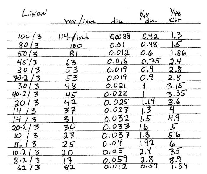
-
I use a lot of lacquer to coat and stiffen my patterns, but I would not enjoy using it inside. The solvent gemisch seems kind of unhealthy. For PVA, I think bookbinders neutral pH - woodworkers PVA is acidic. No data but isn't CA weak in resisting shear forces? I think shear is a major factor with rigging.
-
Your Dremel will get you there. There are external speed controls (solid state) if you find it burns your work. To be prudent, you may wish to avoid buying another powered rotary tool until you are far enough in that you know what you need. Pin vise = hand power- - there is a variety of them. A basic General - 4 size collets - metal swivel is a good first choice.
-
Mike, I also see the ambiguity with the breach rope length, but when thinking about it - do the experiment with the scale model - if the recoil distance is 24 feet? Is it so far as to smash gun crews on the opposite side or roll the gun over a hatch opening ( as much as those guns weighed, there is a chance that only the sea floor would stop it.) The tackle - left taut - it would slightly restrain and spread out the recoil stress. It would also stress the tackle gear and probably shorten its working life. In the ciaos of battle - I wonder if fingers could be lost if the gun were fired before crewman loosening the gear finished.
-
I would think that the goal would be to have the recoil be enough for the gun to be sponged, cleared, loaded, and rammed while inside the ship. Plus, anyone outside the ship would make a tempting target for the Marines of the opposition. But, since the gun had to bet returned to brace the trucks against the spirketting, it would be inefficient to have the hauling distance be any more than was necessary. Keeping the work of hauling at a minimum and having the load and fire interval as short as possible - both important? It seems likely that there were tables giving breach rope length for each caliber or barrel length of gun.
-
JMS, My comments on size were not directed at your work. I apologize for my wording that makes it seem so. I was influenced by pix of recently finished models. I am thinking that in general, the ratlines should be much less than the shrouds they are tied to. Your jig is very clever. It would also work well with a bubble level to assist in keeping the line horizontal. An old technique was to sew the actual ratline thru each of the shrouds and then cover the join with a knot from a separate line trimmed off. I had dismissed this, but with your jig and using a line that is finer than the ratline itself to make the knot, the result may look better. The clove hitch using the actual ratline has always looked a bit "fat" to me and has done for about 40 years now. Using a thinner line should fix the problem of scale with the knot. If the knot material was saturated with diluted neutral pH bookbinders PVA, it should hold well and the ends trim off cleanly. Sorry, more arm chair experimenting here.
-
This is an excellent idea. I wonder how it would work out to use the paper grid and with this tool, instead of working from the top and bottom, to do top-bottom- middle - and then the mid point of the two open spaces. then fill in. This could reduce the effect of a creeping compound error. I am also wondering if the result would look better if the size of the ratline rope was somewhat less than the literal reproduction of the actual scale diameter. The horizontal lines would then fade into the background a bit - which I am thinking would be the way it would have actually looked. Looking at grid-like components - such as window muntins and gratings - given scale effect - would they look more pleasing to the eye if they had reduced scantlings from actual scale?
-
If the problem is the dust settling out in a long run of a large diameter pipe, then removing the dust early in the system would solve it. Place the cyclone trap close to the intake part - it is silent and passive. The manifold piping and valves cold be replaced with just moving the 5 gal bucket with the trap from machine to machine.
-
Bob, I was thinking that a vac will pull the same volume of air / unit of time irrespective of the pipe diameter from infinity to a diameter that is small enough to offer significant resistance to flow. The suction at the business end would depend on the aperture. If the problem is with the flow being sufficient to keep the suspended material in the air stream and not settle out inside the tube, I can see where the kinetic energy within the air stream would be affected by the pipe diameter ( the other factors being constant). I guess this is another Dennis Moore type situation.
-
Bob, Pharmacology here. Thanks for clarifying. My basic education mostly involved linear Arithmetic and Mother Nature's Math is Calculus. My intuition is based on the wrong Math so I am constantly surprised by how things really work. What impressed me the most about the equation was that it does not take much change in diameter to produce a profound effect on air flow in the lungs or blood flow to the heart, etc. - that the smooth muscles that regulate do not need to constrict or contract all that much to do their job. It does not help intuition that Pharmacology tends to use a 16 oz hammer to do a job that a tack hammer would do better. With the sealed type system being discussed here, Although using 4 inch piping for the long runs may be more than is needed and more expensive is space and money, it should not negatively effect the system. The question: does the reduced resistance have a significant effect on the efficiency on the system and the stress on the vac motor?
-
To add some perspective - the formula for flow thru a tube: ( from Physiology / blood flow ) Flow = 4/3 x pi x radius cubed What that means is that small changes is radius has a profound effect on flow. Small changes can have large effects when it is multiplied by itself 3 times. A 2.5" pipe has 15 times the flow of a 1" pipe.
-
Poor results with carpenters glue
Jaager replied to a topic in Modeling tools and Workshop Equipment
Expecting that all PVA brands should behave in a similar way: I use Titebond II - I squeeze a working quantity onto a piece of wax paper. The left over material goes from an opaque tan/cream to a clear amber an no matter how many layers build up - ( I use the same piece of wax paper for a long time) the dried and polymerized glue is flexible. If what you have is brittle when dried - it is likely a bad lot. -
Poor results with carpenters glue
Jaager replied to a topic in Modeling tools and Workshop Equipment
If I read this correctly: you are concerned about PVA-yellow having too weak a bond based on a temporary bond being reversed too easily? First - I think you were lucky that it reversed without major damage. A different type of glue would be more suited for the temp function - although spot and IsoOH to dissolve would work - I just would tend to use too big a spot. If both surfaces are totally covered before bonding, I think the "joint starve" problem is a fiction. The glue works by undergoing a chemical reaction - polymerization - as it dries. It essentially forms a plastic material. With wood, I am very skeptical that all of the glue could be squeezed out - the wood fibers would crush at the clamp face before that happened. The stronger the clamping force- the stronger the bond. Although it is not realistic, the bond would be best if a single chain could reach both wood surfaces. A bigger problem is the nature of the wood surface. More bite is better. I suspect that my compulsion to use 220 grit is right at the point of the surface being too smooth. With planking - I doubt too much force is a practical problem - too little is much more likely. The wood surface should be free of any substance that could interfere with the penetration of the micro chains of polyvinyl as they assemble.
