


Metaspace
-
Posts
30 -
Joined
-
Last visited
Content Type
Profiles
Forums
Gallery
Events
Posts posted by Metaspace
-
-
Outstanding work. What a beauty!
- mtaylor and Forlani daniel
-
 2
2
-
-
-
It's been a while!
Which doesn't mean I wasn't working on the Zeta - just that I did not find as much time, due to some personal matters, and changing jobs. Also, admittedly, the current work on the ship isn't the most exciting, and quite tedious.
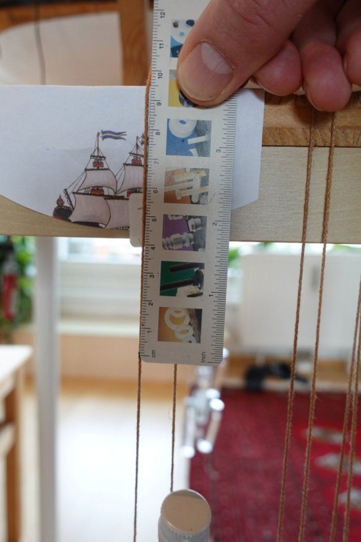
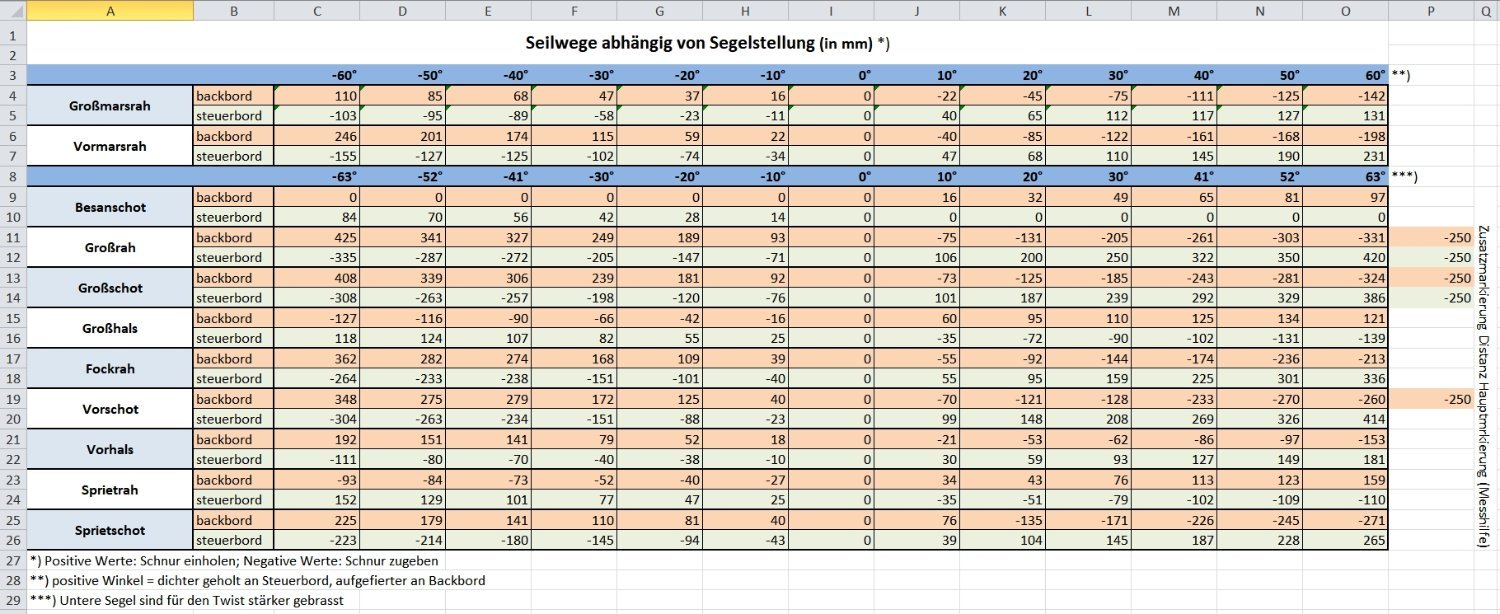
In order to complete our sail steering unit, I had to measure the precise sheet rope movement distances for all sail bracing positions. This data is necessary to correctly dimension the bracing winches later.
My measurement approach is as follows
- all sails were brought into default position (in right angle to keel; except mizzen sail, I'll discuss this later).
- sheet ropes are (temporarily) led out of the hull, to a reference point (in our case, the edge of the table on which the ship resides - the ship being secured against moving)
- sheet rope ends attached to weights, to assure ropes are taut
- ropes are marked at the reference point (sails in default positions; "zero-point")
- now, yards, outhauls are braced in 10° steps (and eased off respectively on the other side of the ship)
- made sure the ropes are all taut
- the difference between reference point and zero-point is measured
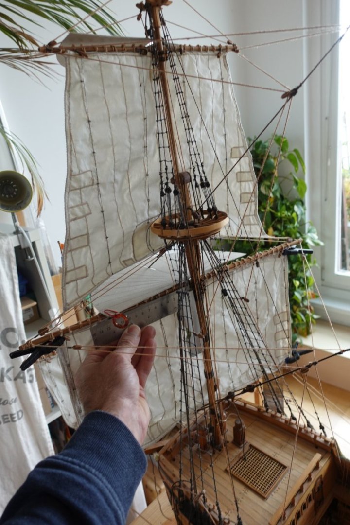
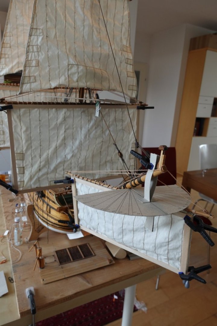
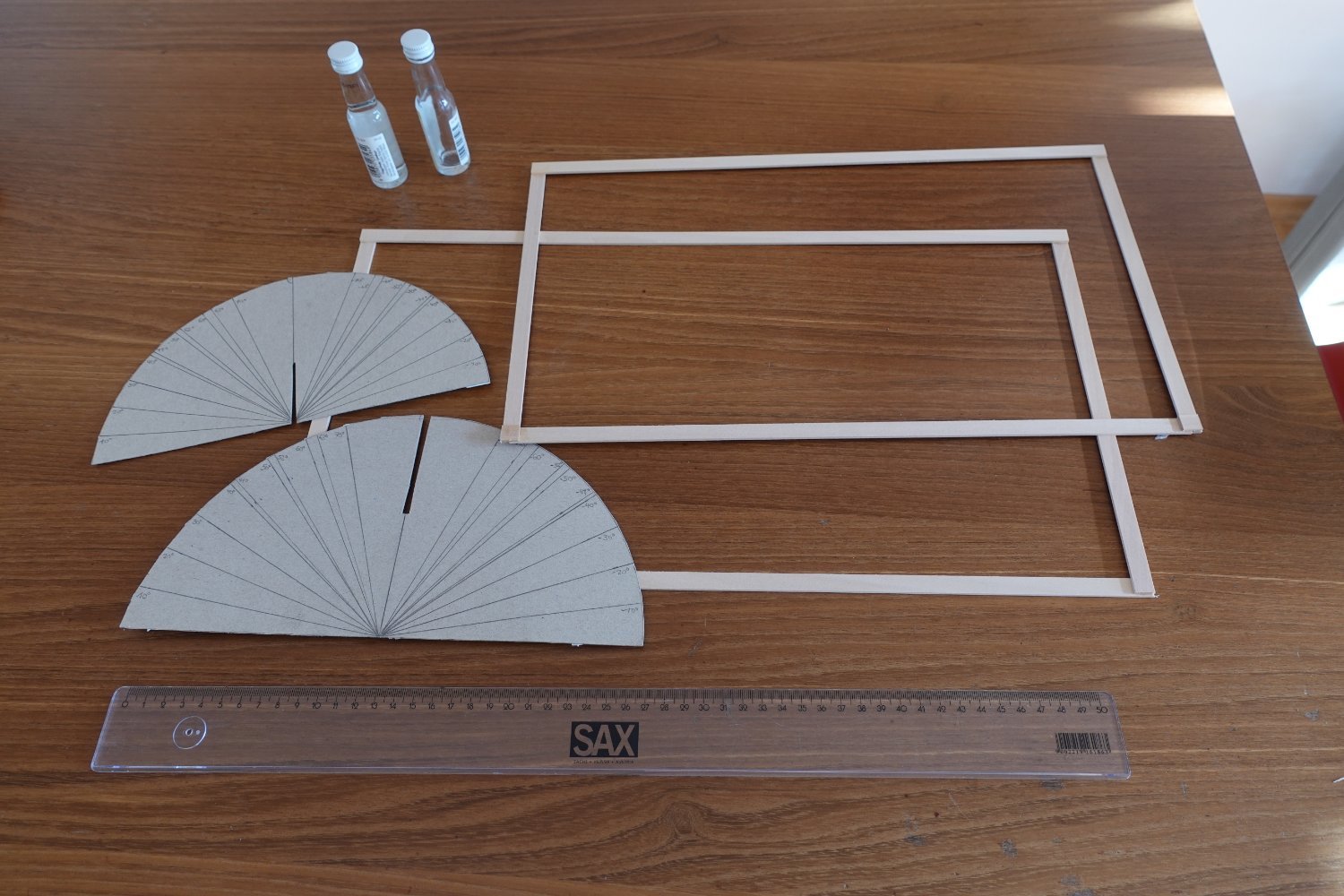
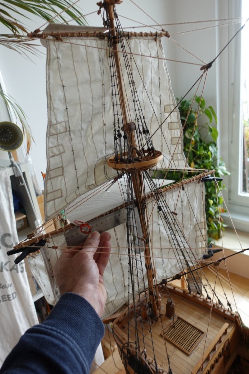
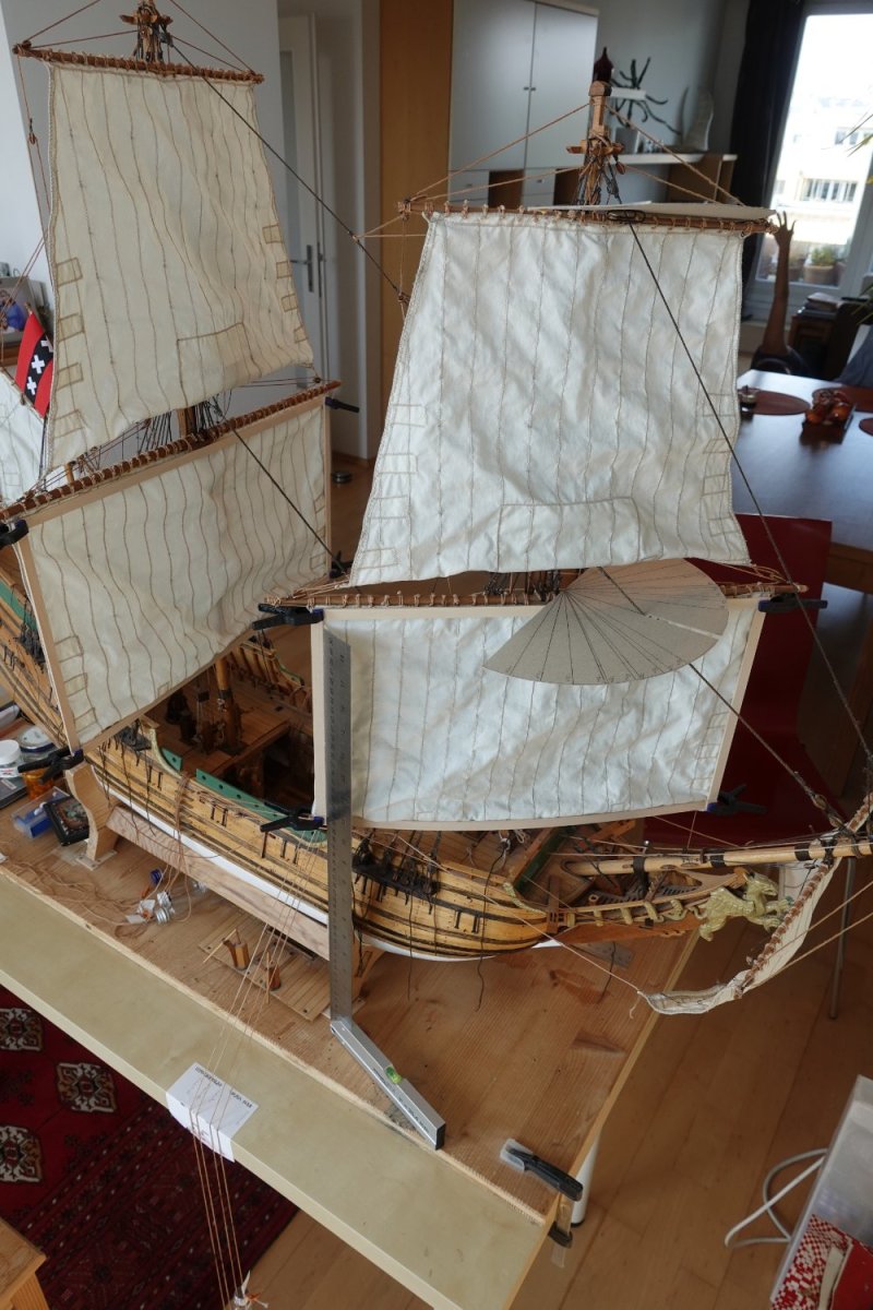
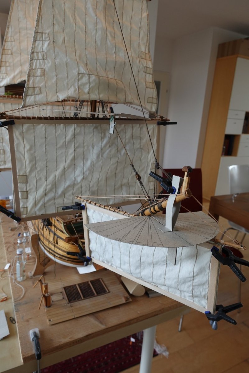
For measuring the correct angles, I used cardboard half-discs with respective markings.
Now I had to take the needed 286 measurements (22 sheet ropes, 9 sail positions) - and this takes a while! When I was done, it turned out that there were some discrepancies between starboard and portside, which were hard to explain by the slight imprecision of the hand-built rigging. Also, some measurement sequences of single sheet ropes from 0°, 10°, 20°, ..., 60°) were not harmonious for my taste.
It took several attempts to eliminate (hopefully!) all measurements errors:
- The angle measurement half-discs need to fixed well, horizontally and vertically
- sheet ropes must not be confused - marking them, as well as their reference points, helps
- the weights for keeping the sheet ropes taut must not be too heavy - otherwise, they might draw additional rope out of the ship unnoticed before the measurement is taken (ropes with a pulley being especially susceptible)
- As our parrels mount the yard relatively loosely on the mast (to allow sufficient rotation of the yard, up to 60°, for remote controlled sailing), the correct, right angle between yard and mast must be assured
- As outhauls are controlled by sheet rope and tack, it must be assured that the sail hangs vertically to the ground, fully stretched, to allow correct measurements. Since the sails warp easily, and normally are not taut, I had to build temporary wooden frames for sails with outhauls (all except topsails), and attach them to the sails to assure the correct shape, and thus, outhaul positioning
The above learnings came at a stiff price - I ended up with taking all measurements 2.5 times. Each time, it means adjusting 8 ropes, cheking tautness, angels, re-adjusting until everything fits properly, and then measuring and taking down the numbers. Only after the last pass I'm fairly confident on the numbers 🙂
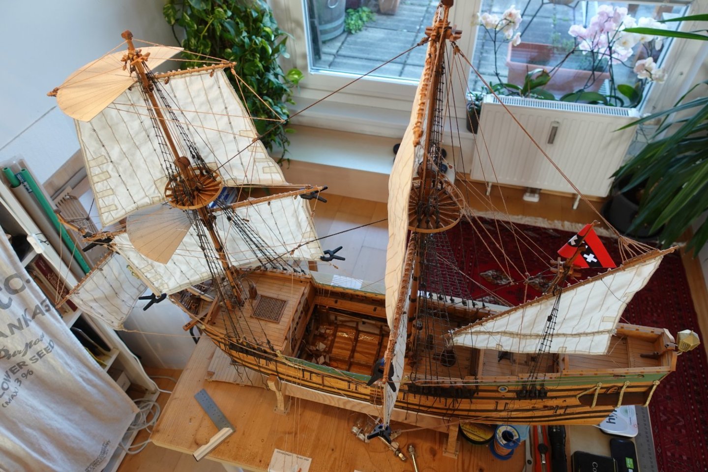
The topsail yards were especially tricky - the ropes controlling them come from below in a quite steep angle - getting the yard position right, without deforming the relatively thin yard was challenging.
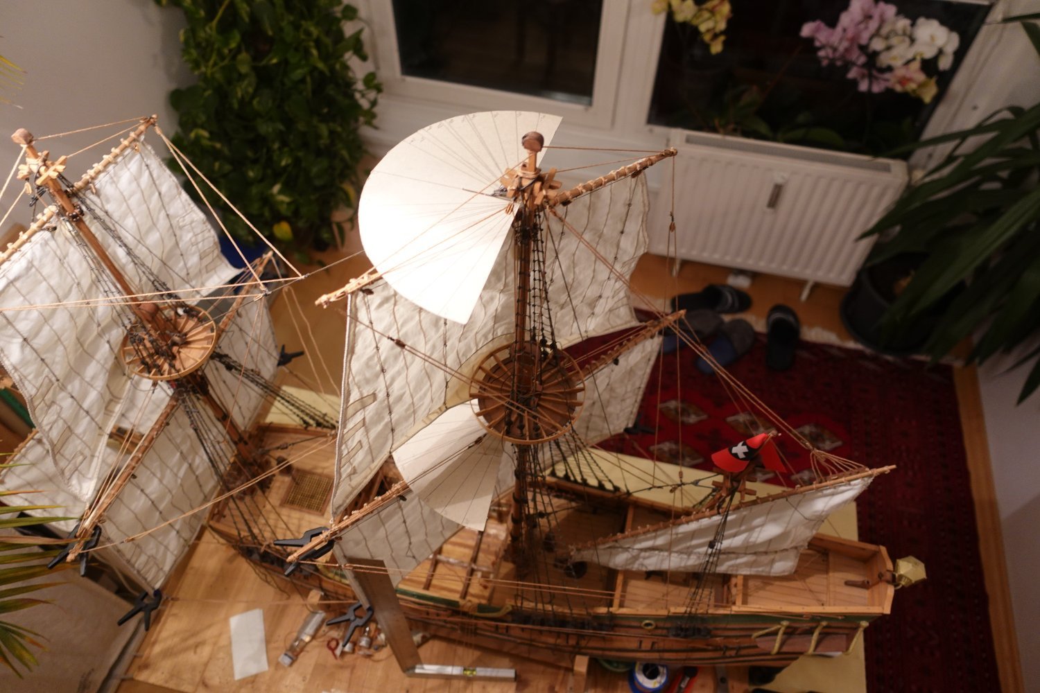
I was quite happy that sails, yards can be well rotated from -60° to +60°, and also the friction of the ropes in their piping is pleasantly low.
Here a few pictures from the measurement process:


The mizzen sail is handled differently. For this, we only control its outhaul - for the mizzen rod, we forgot to lay piping back in the days. But that is not too bad, as the mizzen sail has very limited movement, and is not really relevant for powering the ship. According to the experts, it was used to create rudder pressure, as well as (together with the spritsail) trim the ship.
Under wind from abaft, the mizzen sail will be allowed to take one of two positions - the rear end of the mizzen rod may be fully veered to either portside or starboard (depending on the previous maneuver).
When the ship luffs, the mizzen sail outhaul is braced more and more, until it's fully tight. On the lee side, we do not want to further add sheet rope, i.e., veer, as this rope is in fully veered state already.
This means, the pair of brace winches for the respective side of the ship will pull in rope for the windward side, while adding as little as possible for the leeward side, i.e., that winch will not consist of more than the axle itself.
And here the measurements:

-
-
@Montaigne, many thanks for this insight!
I'm even more awed by this work now 😄 -
-
-
Congratulations! What a great sight. I can't get enough of these images!
If I ever build another model, I'll definitely plan it in Rhino as well 🙂
And I am also excited to see this ship come into being, and for the woodwork to start.
Do you already have plans which wood to use?
-
-
Thank you for the detailed and fascinating insight, and the additional renders!
-
Amazing work!
I'm a bit surprised to see the gun ports of the aft cannos seemingly to be smaller then the rest. Do the guns have a smaller calibre?
With the Papegojan of the same period, with assumedly a similar setup of aft cannons being used either in the rear, or to add to the broadside, were of the biggest cailbre, slightly larger than the rest of the main gun deck.
As I am confident you have done thorough research, would you have an explanation for this? Or am I simply mistaken because of the angle of the drawing? -
8 minutes ago, Waldemar said:
Roman, when do you expect the first sailing trials? Next year season?
Hard to say, the sailing control unit with its 24 bracing winches, plus 24 gear transmission winches will take some time - then the cannons have to be fitted, the mechanism to open the gun ports and deploy them, retract them will be another major effort!
Smaller things will be creating the lead ballast, and the Arduino cannon firing software.
Next year is likely the earliest manageable 🙂- mtaylor, Ondras71 and Deperdussin1910
-
1
-
 2
2
-
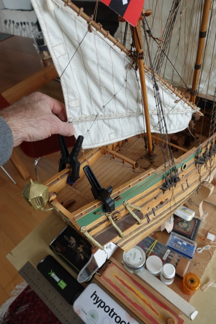
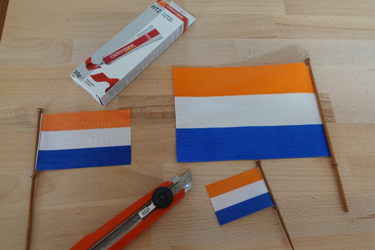
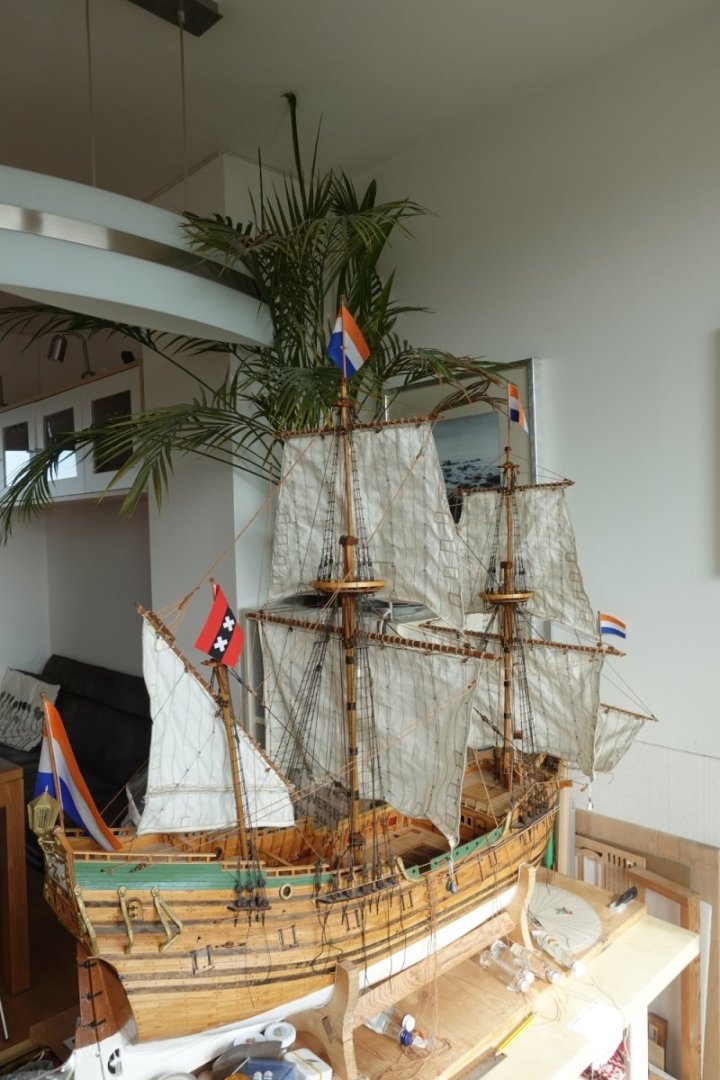
I have added the flags - bought at http://www.schiffsmodellflaggen.de. I'm quite happy with the quality, waterproof (this being a remote controlled model), and a thin fabric, which flows even with light winds.
Instructions came with the flags how to cut them out, and glue them - had been quite a while, since I had a pressing iron in my hand 😄
The flags come in different sizes, not for all flagpoles was I able to get the precise historic size to scale - this is due to our unusual scale of 1:26.67, I assume. Still, I'm happy with the results!
-
-
-
Thank you for all your input.
Just for clarification:
The thing is, as the mizzen sail cannot be fine tuned based on current conditions (due to remote control limitations), I am forced to preset mizzen rod position and sheet bracing based on the angle of the aft yard sails (one servo driving all of them).
As it is considerable effort to define, build, and integrate the relevant brass winches, I hope to not need to have several iterations in order to get them right 🙂
I therefore will go with what looks right. I'm fairly confident the model will sail well enough (as it has a rudder with increased size, as necessary for scale models).
-
4 minutes ago, popeye2sea said:
[...]
So the answer to your question is. Set it however you find looks pleasing to you. It is more than likely to have been put in any position and adjusted depending on steering orders and fine tuning of the sail trim.
Regards,
That makes a lot of sense, thank you!
-
Thank you, yes, I'm aware of this.
The mizzen sail on square riggers is mostly used to create traction on the rudder (by creating additional lateral pressure at the aft of the ship), as well as for trimming the weather helm of the ship.
Unfortunately, form this I still cannot derive the supposed position of the sail...
-
-
Hi model making experts,
my son and me are building a remote controlled version of the Papegojan (1623, scale 1:26.6).
All sails will be contolled as in the original, with the help of bracing winches (I hope this it the correct English term).
Currently, we are configuring these winches, to correctly position the sails for any course in relation to the wind.
What I am not sure about (as I never have sailed on a comparable ship), how is the mizzen sail positioned, braced, depending on the course, and the position of the other sails?
Or, in detail, when the yard sails are braced 10°, 20°, 30°, 40°, ...., in which position would the mizzen rod be, and how tight or loose would the mizzen sheet be?
Can anyone help here?
Thank you in advance. -
Inspiring work! I am looking forward to see more of your beatiful ships!!
- Saburo, mtaylor and MICHELE PADOAN
-
3
-
-
Thanks for your insight! Fascinating! 🙂
- FrankWouts and mtaylor
-
2


„Święty Jerzy” („Sankt Georg”) 1627 – reconstructing an opponent of „Vasa”
in CAD and 3D Modelling/Drafting Plans with Software
Posted
HI Waldemar,
how is your project going? It has been a while since your last post 🙂