ddp
-
Posts
244 -
Joined
-
Last visited
Content Type
Profiles
Forums
Gallery
Events
Everything posted by ddp
-
 i think your black waterline is too high as should be below the reinforcing hull strake not above it according to the US Navy's Booklet of General Plans of that class i have saved on my computer.
- 38 replies
-
- 1
-

-
- Pillsbury
- Clemson-class
- (and 1 more)
-
i have plans for 1958 & 1967, which do you want? will need your email to send them.
-
the bofor mounts will be the same colors as the surrounding camouflage both vertical & horizontal.
-
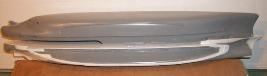
the model is riding to low which means the model is to heavy. even the red part of the hull is to high as the waterline should be just above the prop not as high as yours, even the plan's author's model is riding higher then yours. the plans i linked before shows all that info.
- 51 replies
-
- 1
-
-
- Puncher
- escort carrier
- (and 1 more)
-
i think your model has to much weight causing it to ride low so that even on calm water, the wave action is almost getting into the bow area when compared to this link. https://www.navsource.net/archives/03/0305307.jpg https://www.navsource.net/archives/03/053.htm
- 51 replies
-
- 1
-
-
- Puncher
- escort carrier
- (and 1 more)
-
warm water with dish detergent, rubbing alcohol or both then sun light for 30 plus minutes.
-
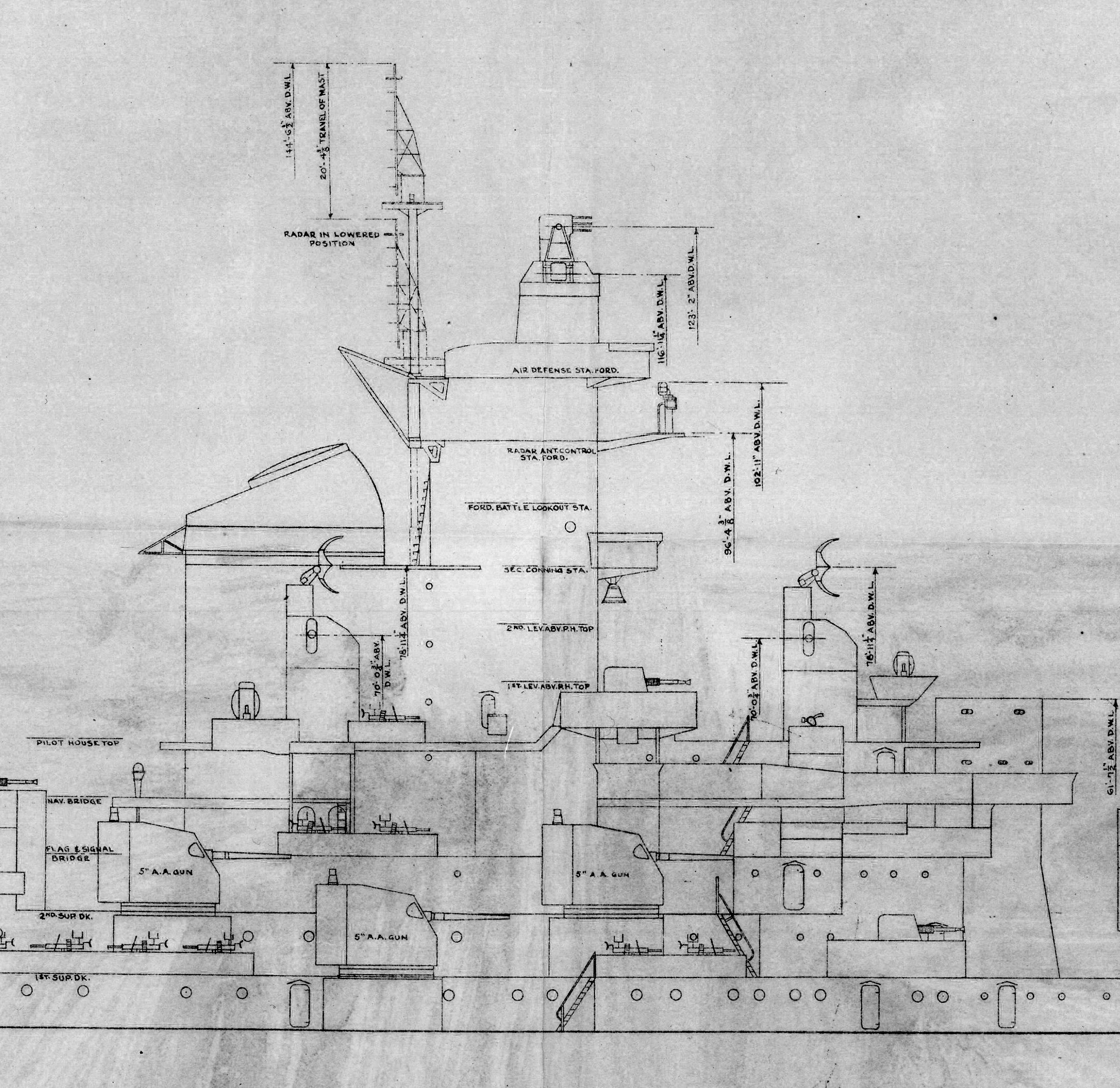
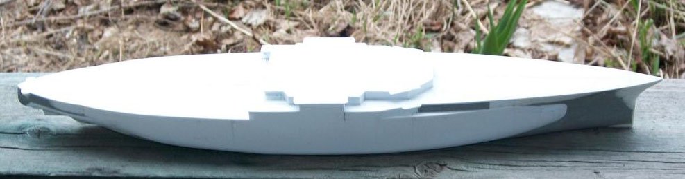
i know that the platform is to overhang but the upper half of the tower is not to overhang but be vertical flush with the lower half of the tower.
-
to me kitbashing is when modifying a model's appearance to look totally different from the original appearance like these. kitbashing Revell's 1/429 scale USS Arizona into the OBBs(old battleships) of ww2 from the Wyoming class to the Colorado class. on the 2nd item, look at this link which is of the real ship as it shows that halfmoon projection that Canute says were it should be. http://www.navsource.net/archives/01/016384a.jpg in this cropped view of the forward superstructure from Missouri's Booklet of General Plans 1944 that i linked above, you can see that except for the different platforms, the vertical front face of the tower is vertically aligned flush unlike yours which is sticking out past the lower part of the tower.

-
would not call it "kitbashing" but "corrective surgery".
-
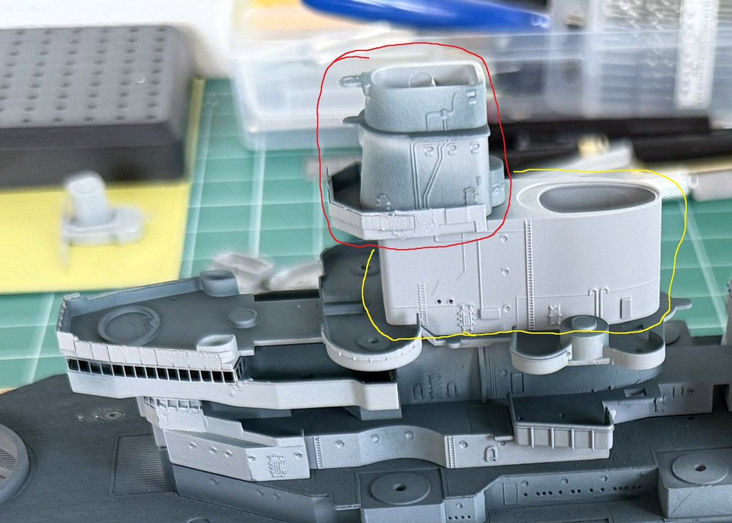
what i am calling the base which the tower is sitting on is actually the "secondary conning station". look at these plans as there is a problem to your model in in that area & maybe more. BB-63 USS Missouri Booklet of General Plans (1944) https://archive.org/details/bb63bogp1944 https://archive.org/details/ship-design-drawings?tab=collection&query=uss+missouri http://www.navsource.net/archives/01/63a.htm
-
is the section of the forward superstructure circled in red glued to the section circled in yellow because if yes then there are some problems. 1: the red section is to far forward causing it to overhang the yellow section as both sections' faces should be vertically flush. 2: the red section minus it's base platform is in reverse in that the flat front should be towards the bow & the rounded angled back should be facing the stern.
-
the stern gun tubs are too far forward causing the catapults to overhang those gun tubs.
-
you must be glad that you also did not glue them solid as then that would be an extremely serious problem to try to fix.
-
if your model had the 2 rudders & 4 props like the real ship had, then your model might have handled better then it currently does.
-
should have put the lead shot into bags so can be removable til all work is done so you would know what lead weight is needed to get the model down to the correct waterline.
-
the model's tower of the forward superstructure appears to be to tall in relation to the heights of the 2 smoke stacks. the ship's profile drawing in the bottom picture backs that up that the tower is too tall.
-
is that hull warped from the swimming pool deck to below the port holes to the right of the clear tape holding the decks to the hull?
-
the layout & shape of the aft superstructure appears to be wrong according to these links. Starboard view off Norfolk Navy Yard, 3 June 1942. http://www.navsource.net/archives/01/015560.jpg November, 1944. http://navsource.net/archives/01/055/015515g.jpg in 1945. Line drawing by A.L. Raven http://www.navsource.net/archives/01/015596.jpg http://www.navsource.net/archives/01/55a.htm
-
Ian, do both props spin in the same direction or does 1 spin right & the other spins left?
-
double check my math to confirm the belt thickness. that is why i said a dremel tool or similar to reduce or remove the belt & replace with new belt so no wavy lines caused by reducing belt thickness.
-
what time period of the war for NC? armor belt thickness for that class would be 12" so at 1/700 scale it would be .435mm thick, do you have a dremel tool or similar to remove that belt & replace with 2 layers of .2mm or 1 layer of .5mm thick styrene sheet?
-
the Princess Royal outboard/inboard drawing i have on my computer as fitted does not show anything in the spotting top.