ddp
-
Posts
244 -
Joined
-
Last visited
Content Type
Profiles
Forums
Gallery
Events
Everything posted by ddp
-
 why did you do a single prop instead of a duall prop that the class was designed for? Propulsion Y-100 plant; 2 Babcock & Wilcox boilers, 2 English Electric steam turbines, 2 shafts, 30,000 shp (22 MW) https://en.wikipedia.org/wiki/HMS_Blackpool_(F77)
 -
could also be some of the Early Essex class ships as some of them had hanger deck catapults til removed later in the war. USS Yorktown (CV-10) 2 H4B hydraulic catapults (1 flight deck, 1 hangar deck) https://www.navsource.org/archives/02/10.htm
-
find out first which part of the model's hull matches the width in the body plan drawing so that you have a base point from which to add or subtract plastic to/from the hull. have you had a chance to look at the link that has the 1940's plans of the Yorktown? right now when looking at the upside down model where the bottom at amidships joins to the sides, it does not look right shapewise for an aircraft carrier but that of a tanker. look at the red circles in the attachment & compare it to the drawings.

-
Patrick, how many pages are your Floating Drydock Plans? are you going to put the armor belt on the hull as i don't see it? i don't you need to cut the hull but maybe pull in the sides part way up the hull when looking at your body plan drawing. how thick are the kit's sprues as could be used to help pull the sides in? what does the bottom of the bow look like?
-
i am seeing something like a docking keel just above the water to the left of the hole.
-
CV-5 USS Yorktown Booklet of General Plans (1940) https://archive.org/details/cv5bogp1940 USS Yorktown (CV-5) https://www.navsource.org/archives/02/05.htm the .50" machine guns are the water cooled version not air cooled.
-
Mike, deck is supposed to be flat & camber is side to side not front to back. have a look at this link. LPH-9 USS Guam Booklet of General Plans (196X) https://archive.org/details/lph9bogp196x Spiff, you are welcome. take a look at that link i just posted.
- 176 replies
-
- 4
-

-
- new orleans
- iron shipwrights
- (and 2 more)
-
approx. how much is the bottom of the bow & stern raised in relation to the midships? had the reverse issue with my 1/429 scale OBB's so i ran them thru a belt sander that resolved that issue as now the keel is flat from bow to stern.
- 176 replies
-
- 3
-
-
- new orleans
- iron shipwrights
- (and 2 more)
-
tape the deck in place not glue it as would be easier for adjustments if deck is removable.
- 176 replies
-
- 3
-
-
- new orleans
- iron shipwrights
- (and 2 more)
-
give a slight sand to both the plastic sheet & the top of the hull to give the glue more surface area to attach to. put a shim or whatever between the deck & hull top but not glued then use the compass at the widest part of the gap with 1 part of the compass sliding across the deck & the scribe part of the compass to the hull at the widest part. slide the top part of the compass along the deck edge as the scribe part of the compass scribes a line parallel to the deck into the hull till you reach the end of the gap. cut away the material above the scribed line till the end of the gap. now the gap should have the same width from the front to the back of the gap which you can now fill with strips of plastic & once the glue has cured, can carve/sand that area to proper shape. once primed & painted, you won't know that there was a gap there. even tho i currently only work with plastic, i use that same principle on my 1/429 scale OBB's & my gaps are almost non-existant with hardly any putty use.
- 176 replies
-
- 3
-
-
- new orleans
- iron shipwrights
- (and 2 more)
-
what glue & what materials are you going to use to fill that gap between the hull & flight deck? do you have a compass/divider?
- 176 replies
-
- 3
-
-
- new orleans
- iron shipwrights
- (and 2 more)
-
how flat does the keel lay on a flat straight surface?
- 176 replies
-
- 3
-
-
- new orleans
- iron shipwrights
- (and 2 more)
-
cut the brass rod flush to the top of the platform then get a solid plastic rod so just fits into the brass rod. taper the plastic rod to the right shape by carving, scraping with a knife blade or use a hand drill/drill press with the plastic rod partly inserted into the chuck to use as a lathe. your picture time frame appears to be around 1974 or earlier because of the mast behind the island which not there in 1975 as replaced with a dome but has the twin 3" gun mounts in those time periods.
- 176 replies
-
- 3
-
-
- new orleans
- iron shipwrights
- (and 2 more)
-
your mast should be tapered, thinner & shorter above the an/sps platform as shown in this link. https://www.navsource.org/archives/10/11/10111131.jpg
- 176 replies
-
- 2
-
-
- new orleans
- iron shipwrights
- (and 2 more)
-
USS New Orleans (LPH-11) https://www.navsource.org/archives/10/11/1111.htm
- 176 replies
-
- 5
-
-
- new orleans
- iron shipwrights
- (and 2 more)
-
then you have to use Measure 11 March/April 1942 to Fall 1943 not Measure 21 Fall 1943 to Summer 1944. http://www.cv6.org/ship/camo-radar.htm so you'll need Wildcats, Avengers & Dauntlesses for that group.
- 154 replies
-
- 4
-
-
- Enterprise
- Trumpeter
- (and 1 more)
-
if the model is supposed to represent mid 43 to 44 then can't have the Wildcats as were on til May 1943 then Hellcats in Nov 1943. you would be using airgroups 6 or 10 for that time period. http://www.cv6.org/company/airgroups.htm http://www.cv6.org/ship/big_e.htm
- 154 replies
-
- 4
-
-
- Enterprise
- Trumpeter
- (and 1 more)
-
go thru this link https://www.navsource.org/archives/02/06a.htm to look at all the war time pictures to locate most if not all the life raft positions. the rafts would be painted the same color(s) as the location it is in so can have more that 1 color depending on the camo scheme used.
- 154 replies
-
- 4
-
-
- Enterprise
- Trumpeter
- (and 1 more)
-
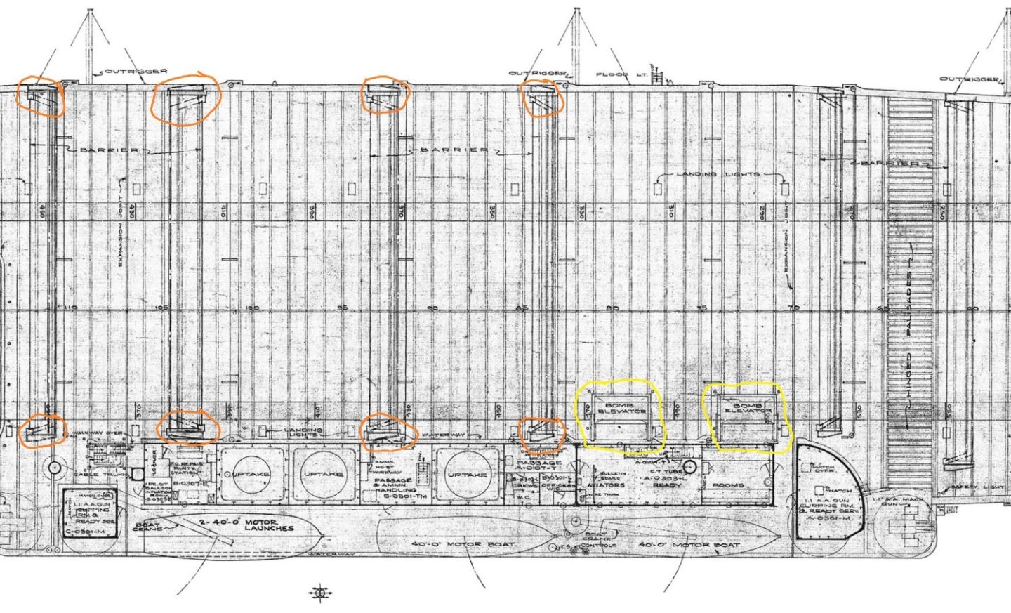
take a look at this link https://www.navsource.org/archives/02/020667.jpg as can just see the 2 bomb elevators. "The "Big E" had her island modified during her July-October 1943 refit. Note new platforms on both the navigation and flag bridges, for better visibility, and Mk.37 dual purpose director (with Mk.4 radar antenna) in place of her former Mk.33. Photo taken on March 20, 1944 from one of her own planes." https://www.navsource.org/archives/02/06a.htm
- 154 replies
-
- 4
-
-
- Enterprise
- Trumpeter
- (and 1 more)
-
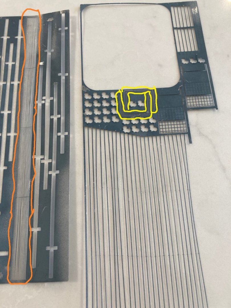
so you are talking about the orange circled objects on the left & the yellow circled objects on the right, correct? can you post a close-up shot of the area you think are "vents" as i think they are the 2 bomb elevators? on the 2nd picture, is the yellow circled objects the "vents" you are talking about & do you have the orange circled objects in pe or plastic as those appear to be the ends of the crash barriers?
- 154 replies
-
- 4
-
-
- Enterprise
- Trumpeter
- (and 1 more)
-
can you point out the 2 things so we know what you are talking about?
- 154 replies
-
- 2
-
-
- Enterprise
- Trumpeter
- (and 1 more)
-
on that model, those raised lines can be scraped/sanded down smooth whereas on the Nagato model, the lines had to be filled in with plastic strips or putty then sanded smooth.
- 97 replies
-
- 2
-
-
- Curtis Wilbur
- I Love Kit
- (and 2 more)
-
9 wires would be from almost at the stern to the midships elevator according to the sheet 6 flight deck plans. that is CV-14 USS Ticonderoga, an Essex class aircraft carrier, the successors to the previous Yorktown class that your model was part of. https://www.navsource.org/archives/02/14.htm i have 6 sets of Booklet of General Plans of the angled deck Essex class saved on my computer the plane guard was most likely a destroyer from 1 of about 5 different classes.
- 154 replies
-
- 2
-
-
- Enterprise
- Trumpeter
- (and 1 more)