

Herby63
-
Posts
102 -
Joined
-
Last visited
Content Type
Profiles
Forums
Gallery
Events
Posts posted by Herby63
-
-
Merit steps 14 to 19:
The louvres were glued to the venttops, the vents glued to the middle deck;
Bulkheads glued with Revell Contacta professional.
All PONTOS hatches and rails glued to the middle deck. Unfortunately The Pieces H16 were replaced with Pontos-parts with other dimentions, so those did not fit. (I stied a couple of times to obtain the correctionfret #12, but with no succes) Si I end up using the Merit parts. Lost between the middele deck infrastructure this will not stand out.
Sides A16 and A17 glued to the sides.
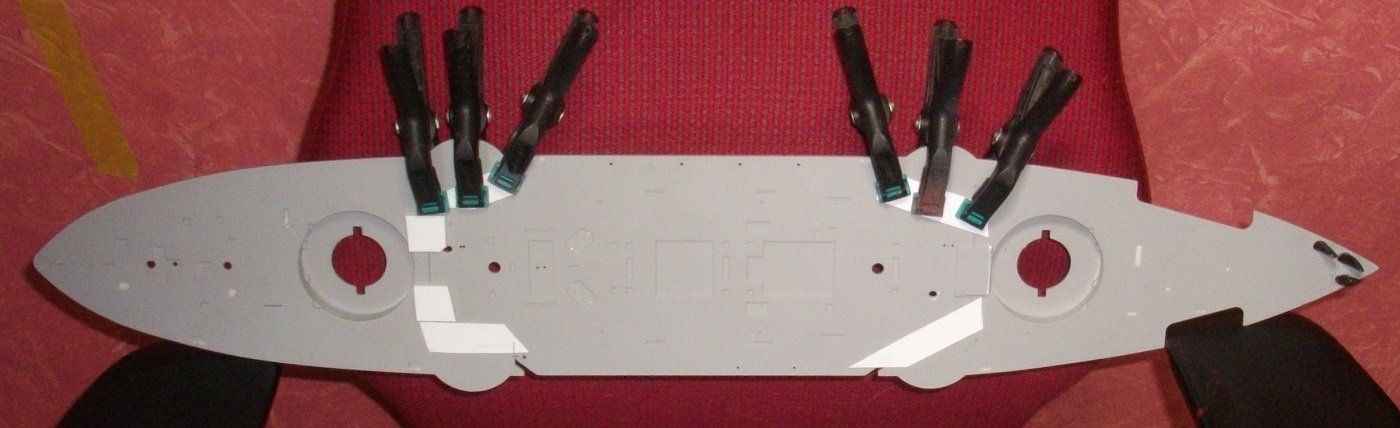
6 and 3 inch guns glued in place with PVA-glue
Untill next update, enjoy modelling.
- GrandpaPhil, yvesvidal, mtaylor and 1 other
-
 4
4
-
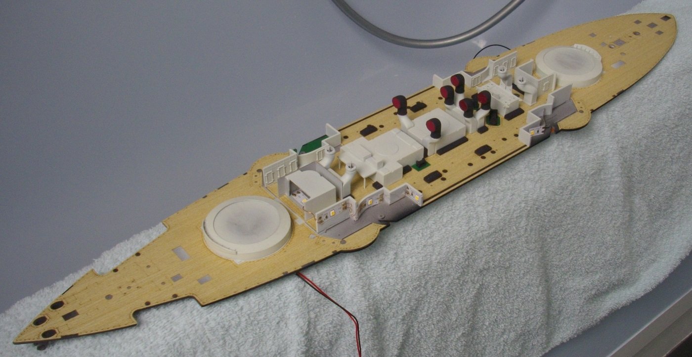
I wired up some LED's with 0,03 mm coated wire and tested for half an houher to be sure the wires did not get hot.
Untill next update, enjoy modelling.
- GrandpaPhil, Ryland Craze, mtaylor and 2 others
-
5
-
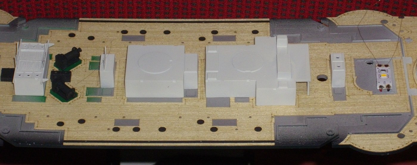
The sides of the middle part of the wooden deck were finished by adding the Pontos brass strips and a fine wooden strip. The brass strips were layed between the wood veneer, and not on it. Thus no unevenness was created . The shute covers were also glued in their place with PVA-glue.
Untill next update, enjoy modelling.
- Ryland Craze, mtaylor, GrandpaPhil and 2 others
-
5
-
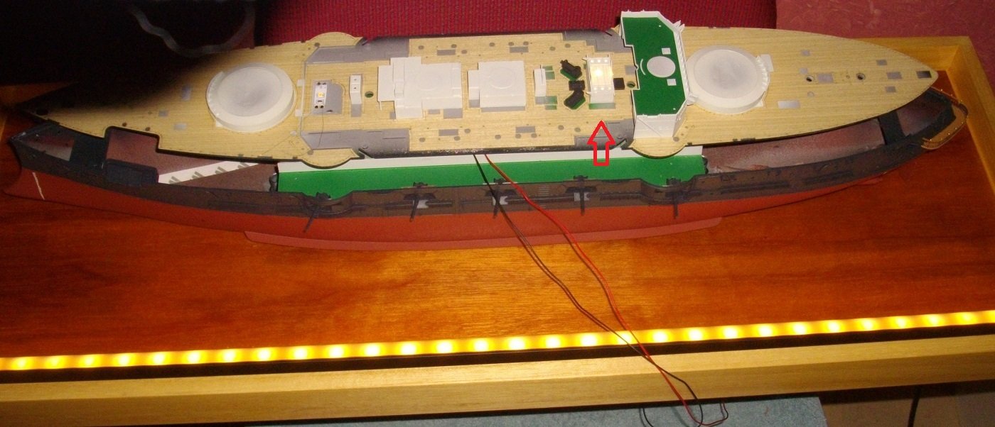
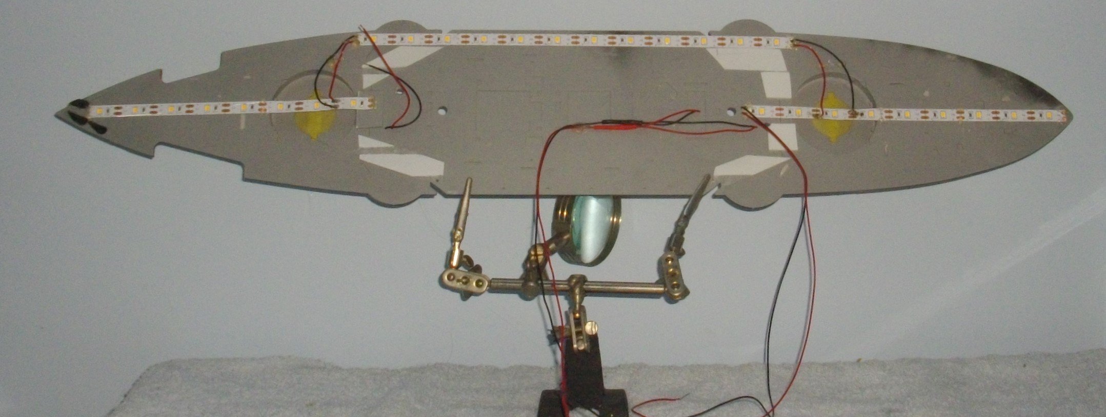
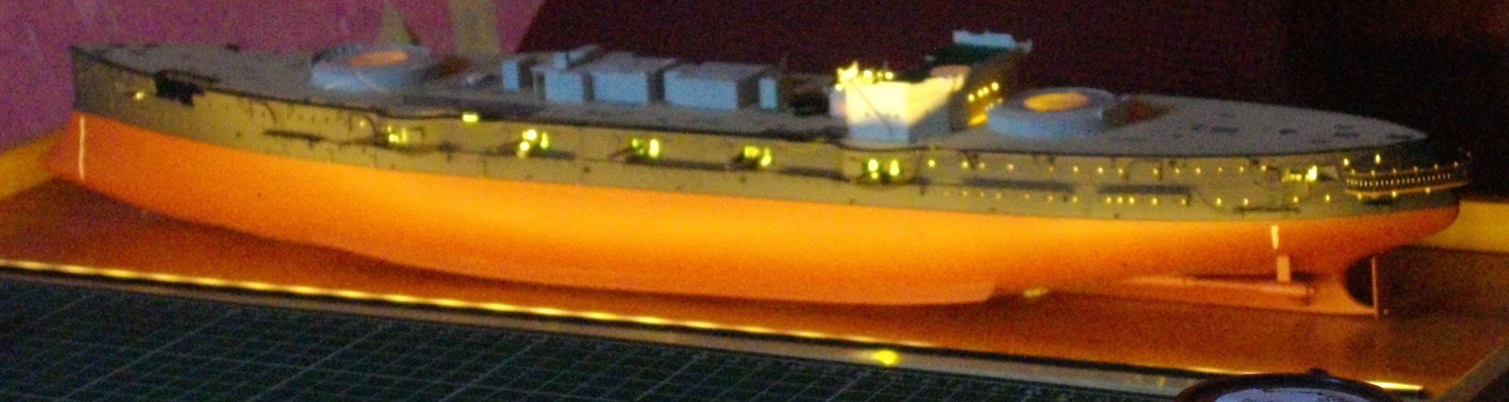
I then connected the LEDstrips for lighting up the hull to the underside of the deck.

and enjoyed the atmosohere during a brief test.

Untill next update, enjoy modelling.
- GrandpaPhil, Canute, mtaylor and 1 other
-
4
-
I used some PVA-glue to stick the Pontosparts for Merit step 12 to the middledeck, except for the shutecovers.
Then I wired up a double LED to go under a part of the superstructure.
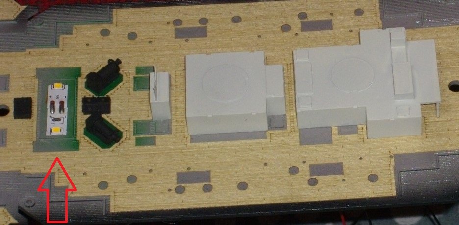
I put on the cover and tested it.
Untill next update, enjoy modelling.
- yvesvidal, GrandpaPhil, ccoyle and 3 others
-
6
-
I placed some central bulckheads on the center deck to enture a perfect positioning of the wooden deck, removed the plastic backing and gently and evenly worked it down over the bulckheads with a pair of tweezers until it touched the styrene deck. Then I rubbed it down with a piece of wood.
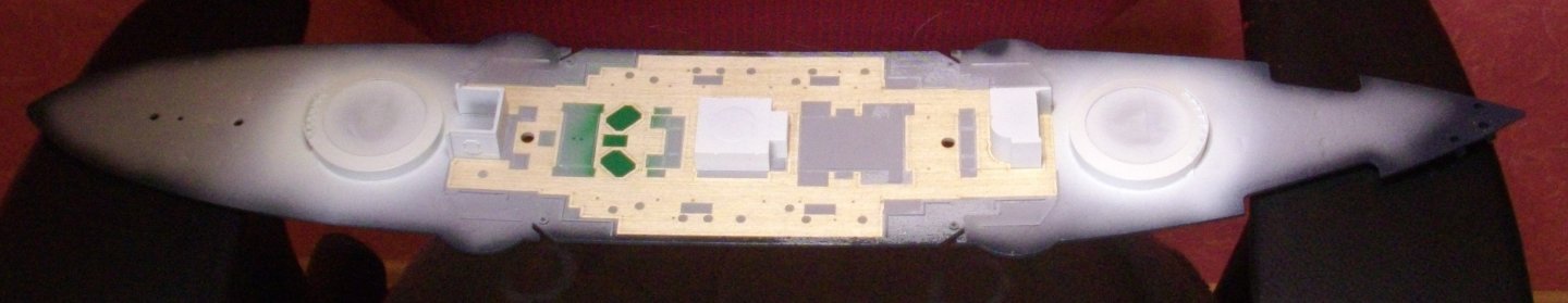
For the fore and aft sections I put some cocktailsticks on the deck to allow perfect positioning before tacking down.
Untill next update, enjoy modelling.
- Canute, mtaylor and GrandpaPhil
-
3
-
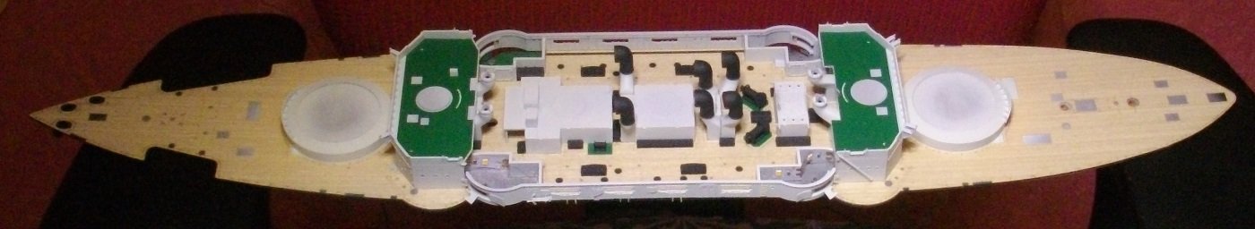
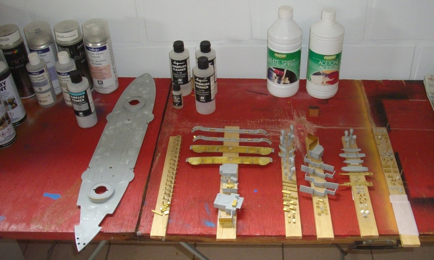
Finaly some painting can be done.
The metal parts were primed with VMS Metal Prep 4K first.
Then all parts were sprayed with a grey Vallejo primer for plastic and metal.
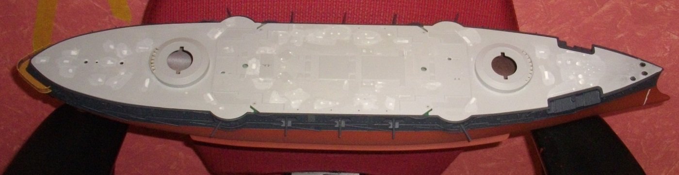
The sides of the deck have been painted Black Grey, in case the wooden deck leaves some edges visible.
The barbettes of the main guns have been painted Insigna White, the base plates for the winches have been painted Deep Green with a drop of Buff and the whole deck has been finished wit a coat of clear gloss varnish. The Pontos wooden decks have a reputation of lifting after some time, but Steve of "The model shed" claims spraying a coat of gloss varnish first has not let him down so far.
All bulckheads and the boatdeck are painted Insigna White.
The deckdetails and furniture are painted Black Grey, a personal choice. 😁
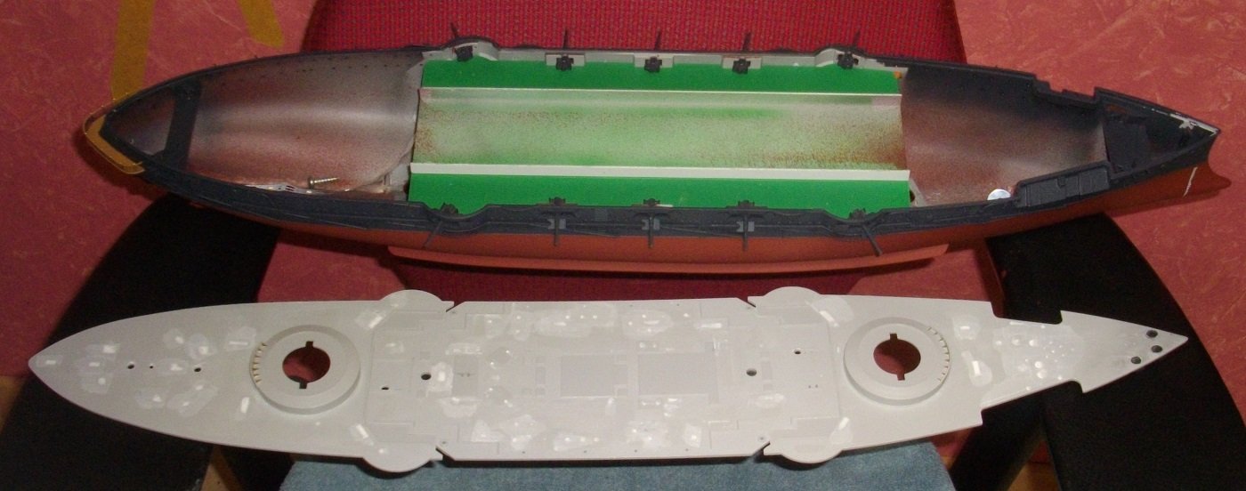
The metal decks of the bridges, which have not yet been glued down are painted my special blend of deep green.
The louvres for the vents are painted Red.
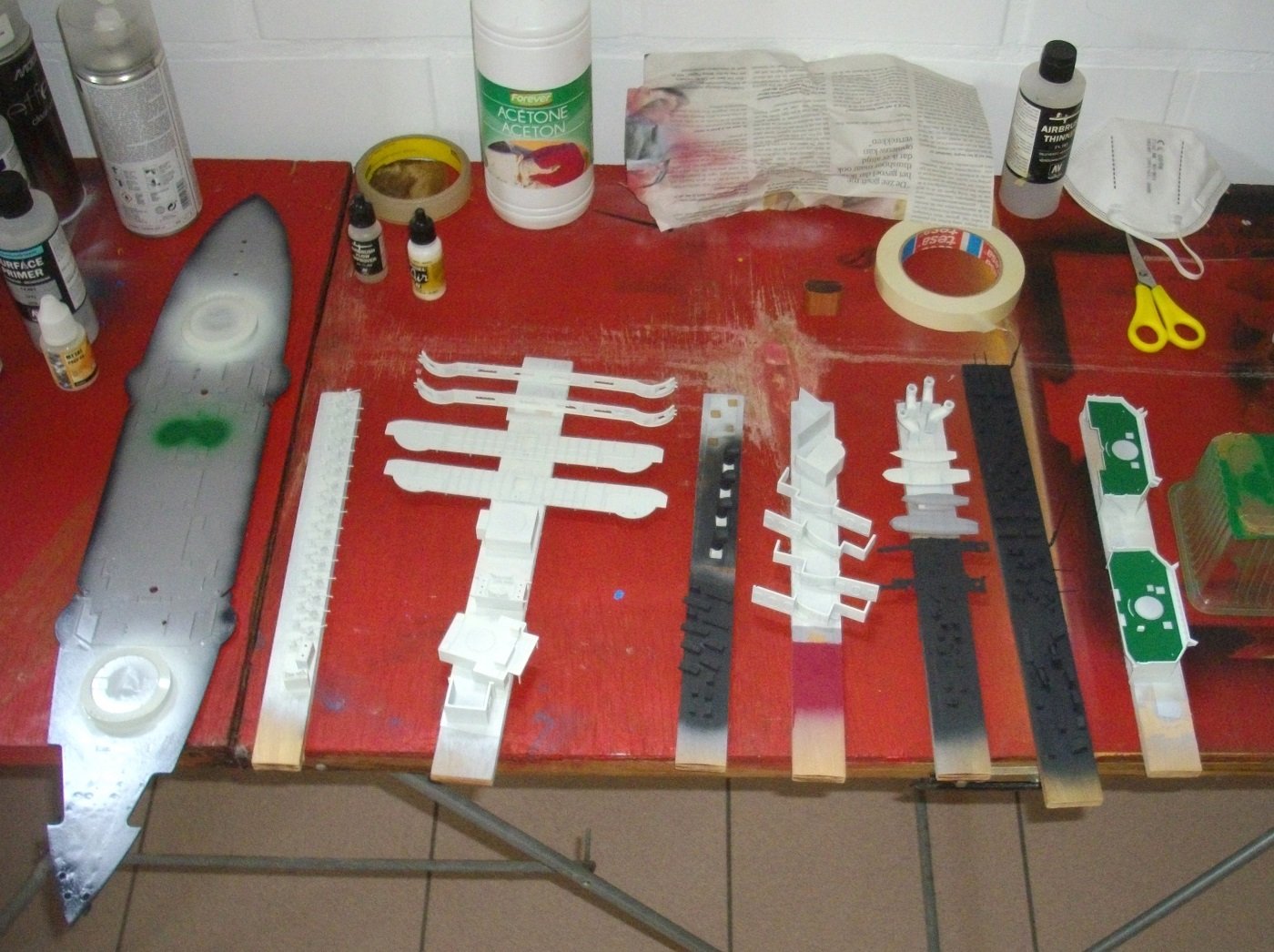
Untill next update, enjoy modelling.
- mtaylor, GrandpaPhil, yvesvidal and 1 other
-
4
-
On 5/15/2024 at 12:16 AM, Jeff59 said:
Mind watch out for position of 6 inch guns on main deck, think they need moved outward 2 to 3mm to let the guns sit more in middle of housing, l didn’t do this but would if l were to do it again, the gun should be able to run parallel to side of bridge superstructure, you’ll see what l mean when you investigate it.
Oups, too late, installed them today, does not look too wrong. I dont intend to position them parallel to the side of the bridge, so only people who have thouroughly investigated this ship will know, and there are not that many around, certainly not in Belgium. 😁
I shall post an update soon.
Thank for your comment, I try to consult your build every time I attack a new area.
Kind regards.
-
-
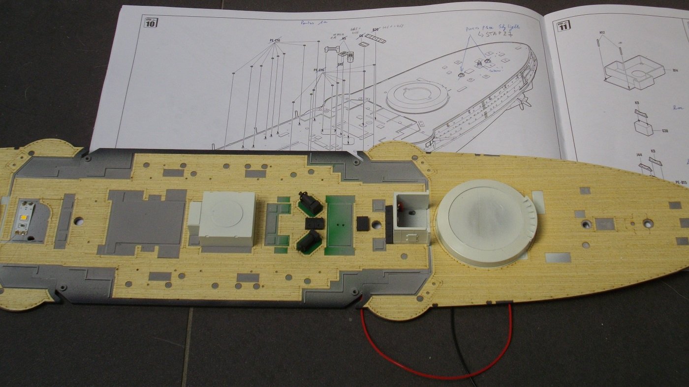
However, some more preparations are needed prior to painting.
I did a test soldering coated copper wire to the LED-strip, which went perfectly when the temperature was high enough to burn the lacker away, but I doubt if the 0,08 mm diameter wire is heavy enough to put 4 LED's in a row. According to my calculations I need at least 0,2 mm thick wire.
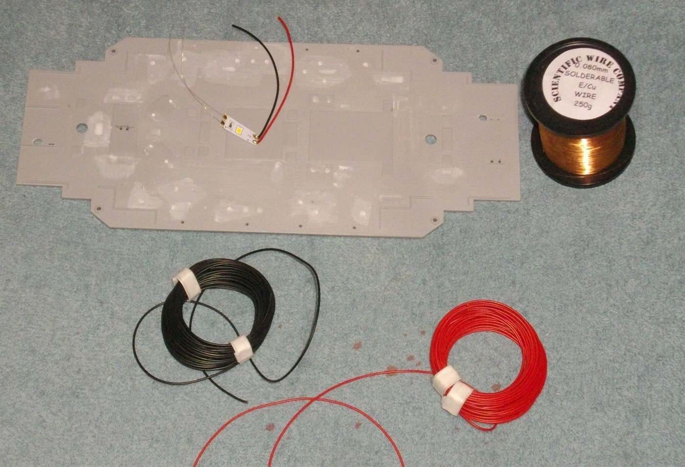
As multiple LED's will be installed in the superstructure, holes must be drilled in the deck.
It would also be nice to be able to remove the deck in 1 piece, so I used some syrene to glue the 3 pieces together.
a perfect fit
and after buffing the sides, it can be taken out without too much force.
Until next update, enjoy modelling.
-
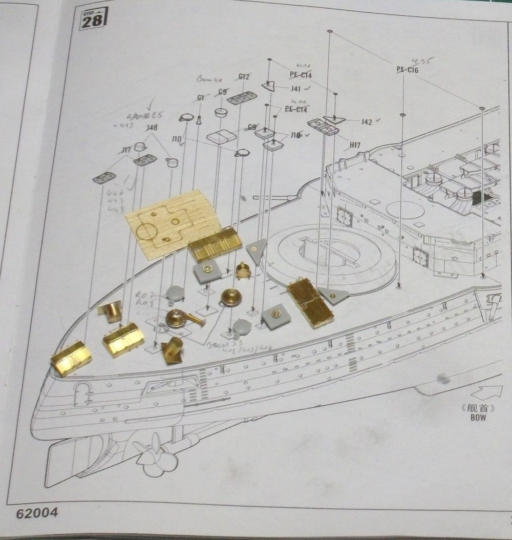
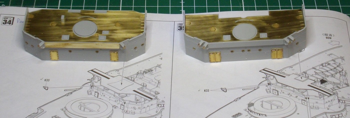
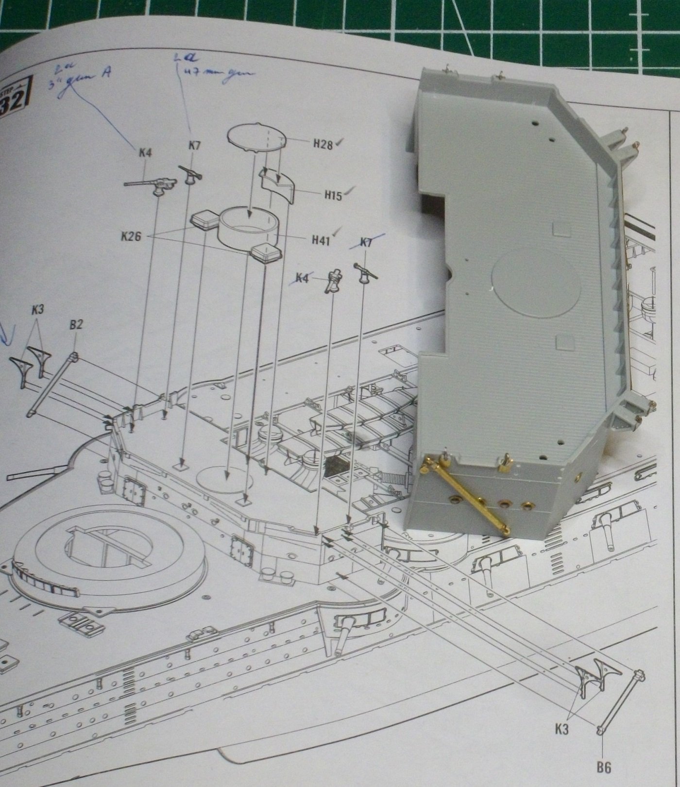
Finaly the furniture for the aft deck, as shown in steps 28 and 29.
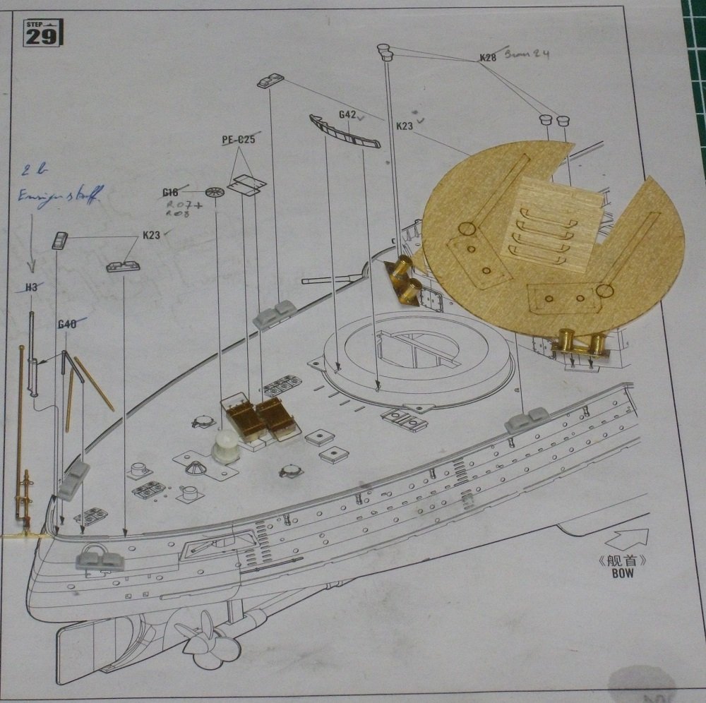
Now it's time to paint a little (a lot ! )
Until next update, enjoy modelling.
- Canute, yvesvidal, GrandpaPhil and 1 other
-
4
-
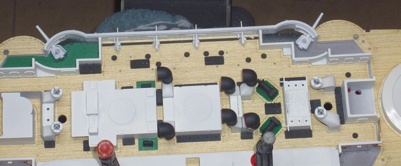
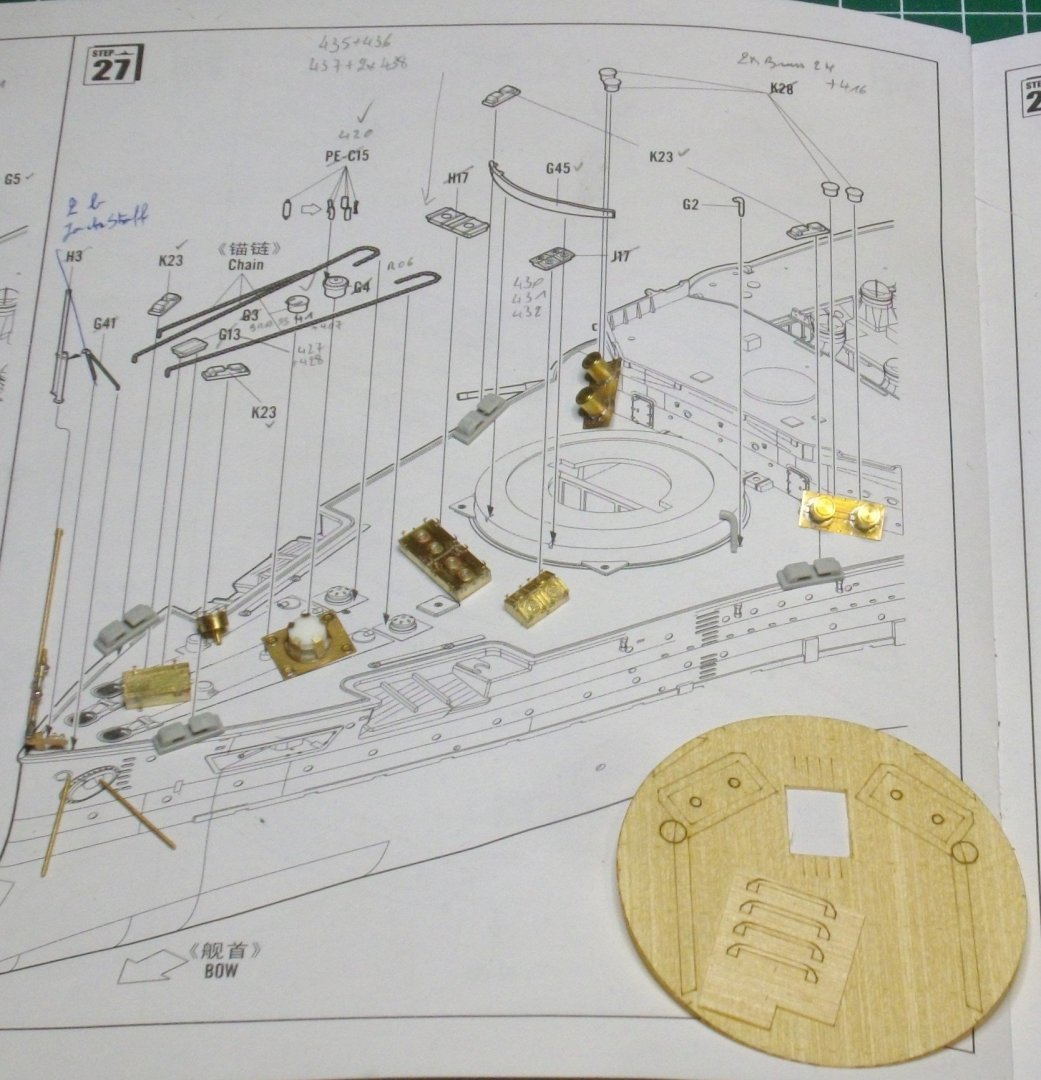
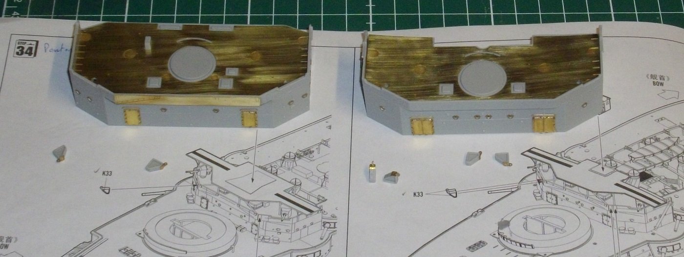
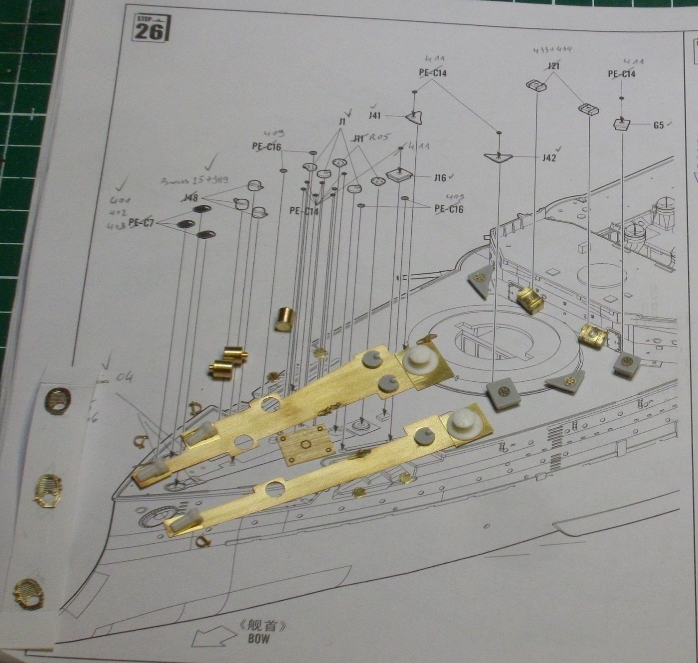
And some more features of the fore deck.
Only the grey stuff is Merit, all the rest is brass and resin from Pontos.
Until next update, enjoy modelling.
- Haliburton, GrandpaPhil, Canute and 2 others
-
5
-
-
Congratulations with the marvelous model, the inspiring buildlog and the many trophys
- hollowneck, Canute and mtaylor
-
3
-
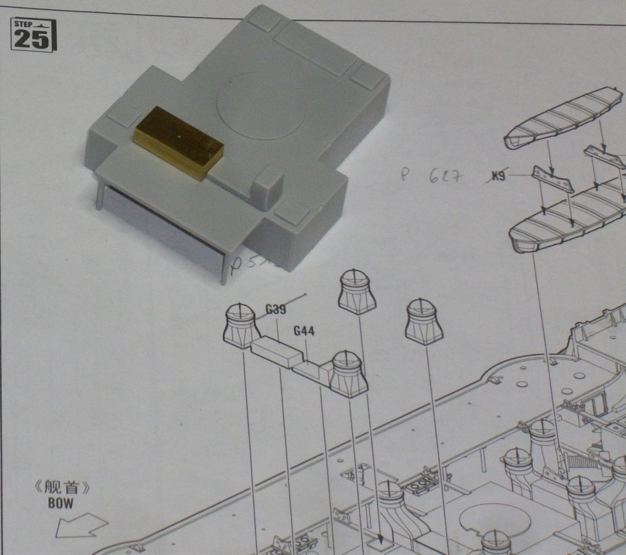
Back to the model:
The last part to prepare for the middle part of the main deck.
Pontos part 519 is bent into a box and soldered, and glued with Merit part G39 to the fore funnelbase.
Until next update, enjoy modelling.
- Haliburton, mtaylor, yvesvidal and 2 others
-
5
-
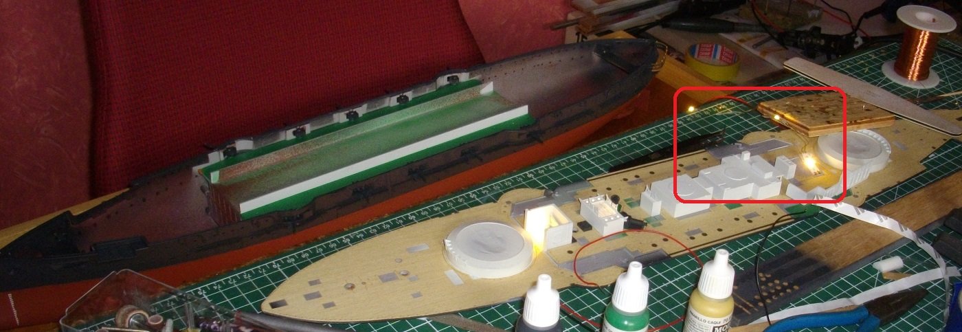
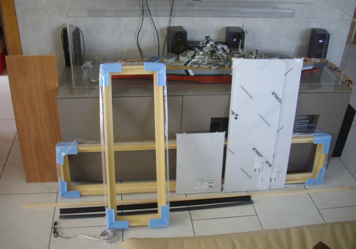
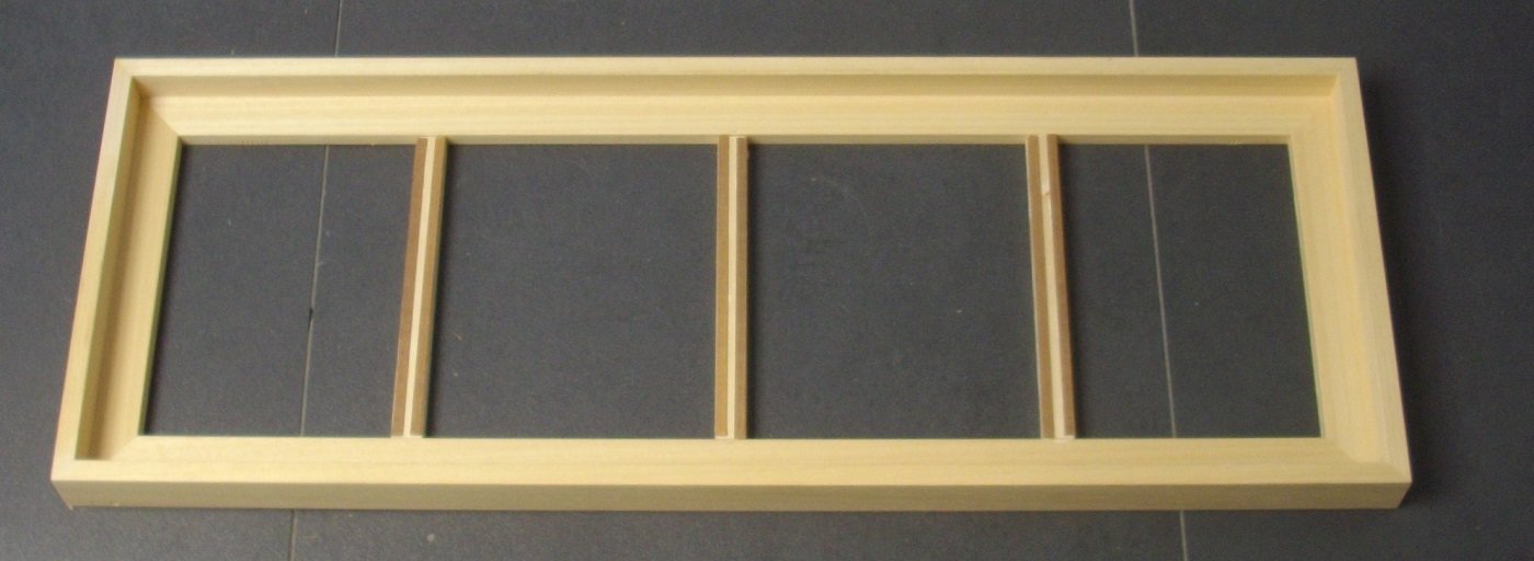
As promissed a few post ago: the displaycase.
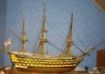
As I would never have been able to make such perfect joints, I ordered 2 frames, one for my next project, a fully detailed DKM Bismarck (the one in the picture is operational and thus not so detailed) and one for MIkasa (standing).
They came in at last.
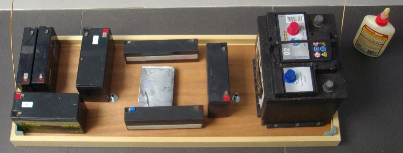
In the picture below:
- the 2 frames
- bottomplate for Mikasa
- plexiglass sheets cut to measure
- 1 woodn beam 12 mm thick (as thickness as the horizontal part of the frame
- 1 aluminum profile for LEDstrips
- 1 grey cover for the profile in order to difuse the light
- 2 meter Ledstrip 5V with USB-connector
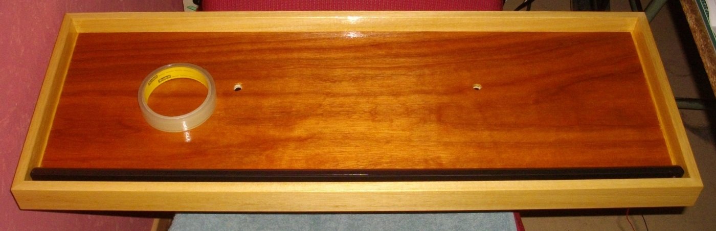
First I drilled a 4 mm hole through the horizontal part of the frame.
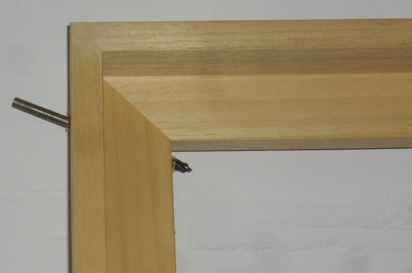
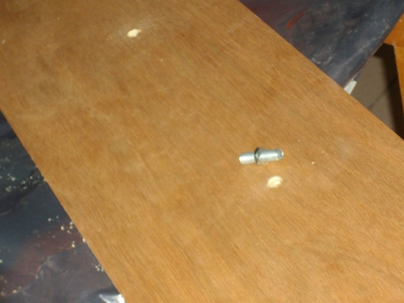
I drilled 2 10 mm holes for the lampfittingparts (hollow threaded rod 30 mm in length) at a distance exactly maching the holes in the bottom of the model.
The 12 mm thick slats turned out to be just a tiny bit less thick than the frame so I cut them to length and added some leftover wood from my Victory-project.
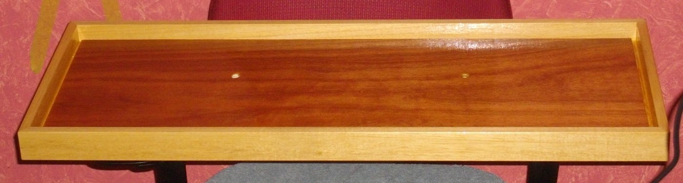
The bottomplate is now glued in the center of the frame.
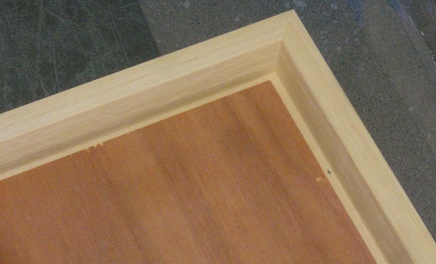
and weighed down.
After glueing the plexigglass (polycarbonate) I testfitted the showcase in the frame.
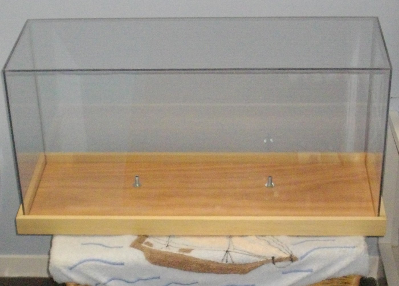
glueing leaves to be desired, but the fit is perfect.
While the clear varnish is drying,
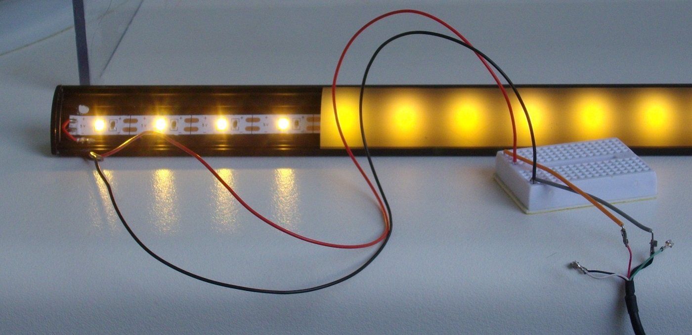
I cut the aluminum profile to length to fit exactly in the case, wired up a corresponding length of LED-strip and glued the strip to the profile.
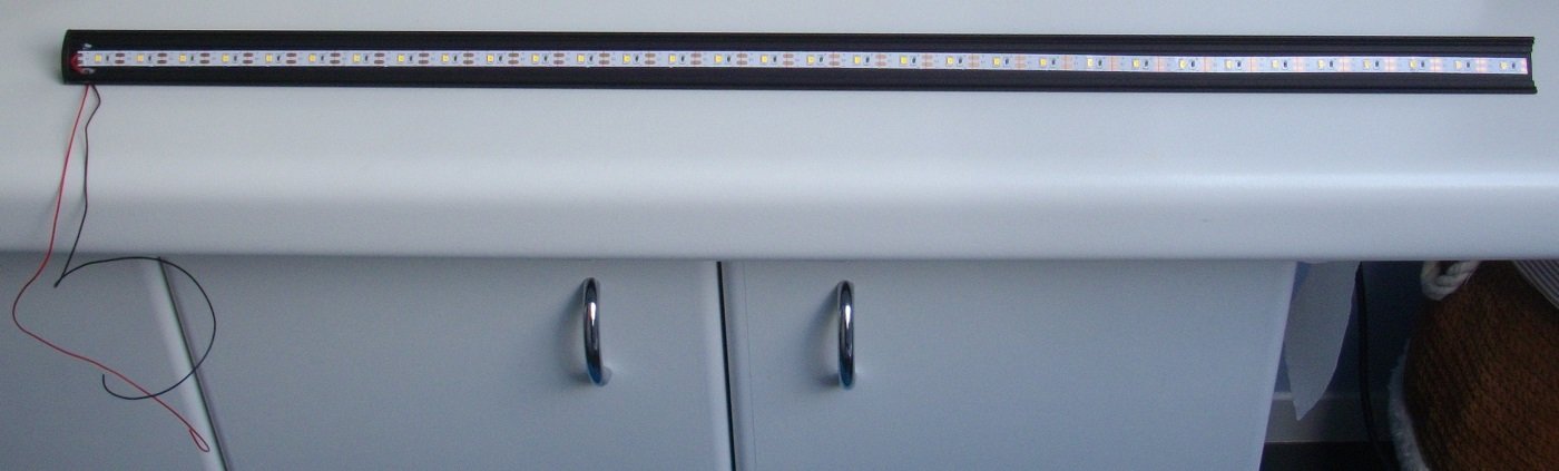
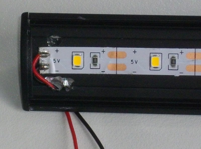
Test of the connections
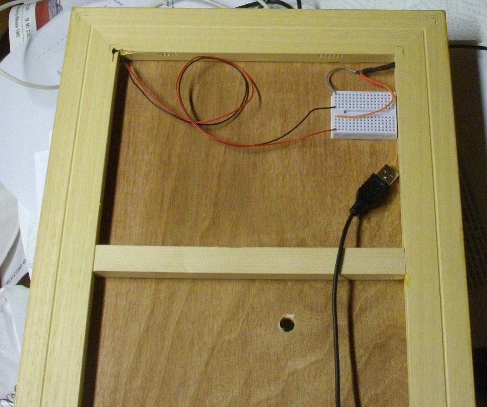
Profile attached to the baseboard with superthin double sided tape
As the USB-cable was rather short, I replaced is by a computermouse cable.
Here the connection at the underside is shown, easy to repare or replace and allows for many connections to be added as I plan on lighting up the model from within as well.
And finaly a picture of the hull on the stand with LED-strip lit (too much light in the room to fully appreciate the effect of the warmwhite light).
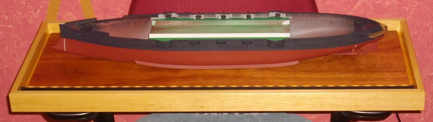
Until next update, enjoy modelling.
-
Thanks to the followers for clicking the 👍-button.
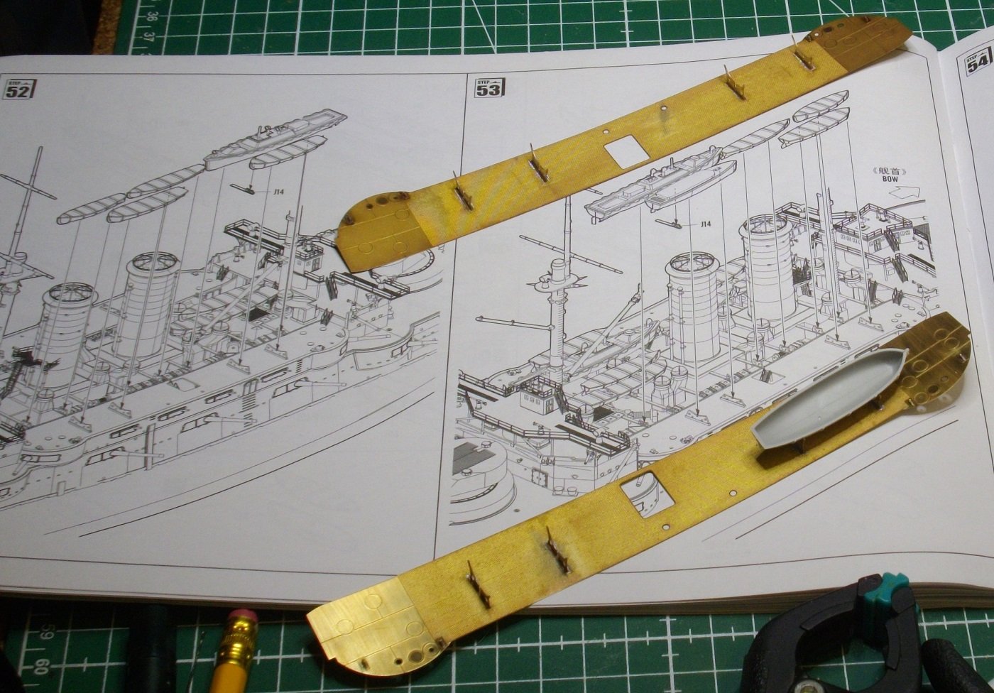
Inspired by the success in soldering the handrails to the front plate of the aft bridge, I released the front plate of the fore bridge, which went surprisingly easy.
After repeating the soldering process and roughing up both contact surfaces with a coarse sanding stick, I glued the plate to the front of the bridge again.
Then I filled up the small holes in the sides of the aft bridge, soldered the parts for the booms and glued them with SloZap to the sides.
Until next update, enjoy modelling.
-
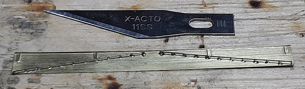
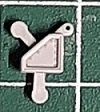
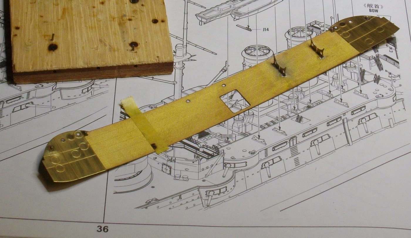
I took a second chance on soldering the handrails to the front plate as this has to be done on the aft bridge as well.
SUCCES this time. In stead of applying the soldering paste to the pins of the handrail, I put the smallest amount on the points on the plate. First I soldered the ends , straightening the brass plate against a steel pin and then, one by one, the other points. (the knife is only for reference)
Next I bent and soldered the brackets to the bottom plate. The 2 outside ones are at a 45° angle.
Finaly I glued both plates to the Merit bridge, using both yellow (thick) and pink (thin) Zap CA-glue.
Until next update, enjoy modelling.
-
I pimped the merit brackets for the mast stays pith some Pontos parts (Nrs 157 en 158)
and attached them to the fore and aft bridges.
Then I soldered the brackets (Pontos parts 513 and 514)together and attached them to the sides of the bridges with CA-glue.
Until next update, enjoy modelling.
- ccoyle, Haliburton, king derelict and 3 others
-
6
-
Time for a little update.
I drilled out the porthols and glued the messing parts.
Then I soldered the doors from the back and glued them with PVA-glue to the bridges (single doors to the front bridge and double doors to the aft bridge).
Until next update, enjoy modelling.
- king derelict, Canute, Haliburton and 3 others
-
6
-
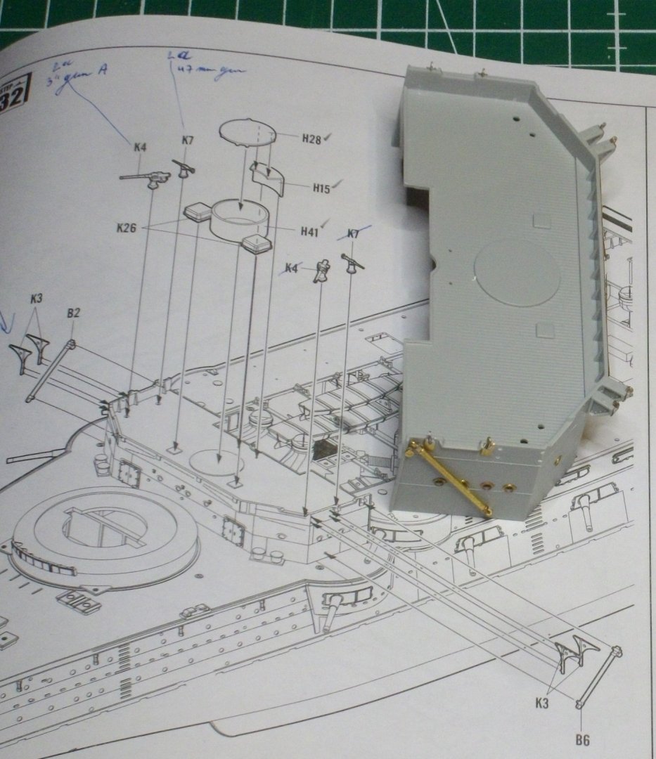
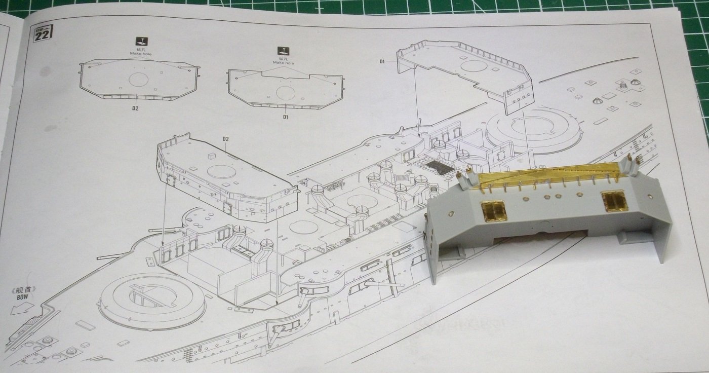
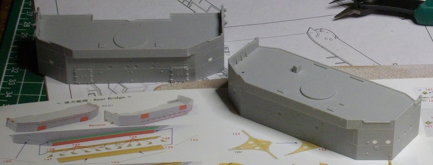
Fore bridge:
I tried soldering the parts shown in the bottom left corner of the previous picture.
The brackets on part 138 went OK.
The handrail to part 139 however did not want to stick.
I had to clamp down this piece as it was bent due to the etching process.
The contact points were so small and the heat could not be applied in such a way that the very small amount of soldering paste woul melt.
So i glued the handrails with PVA-glue.
The rails to the sides of the bridge I glued too, in order not to mix them up (error in Pontos instructions, numbers are switched).
This was not a good Idea.
The handrails are easily knocked off when handeling the part.
More about that in a future update.
Till next update, enjoy modelling.
- ccoyle, yvesvidal, Haliburton and 3 others
-
6
-
Fore and aft bridge:
I started removing all details that will be replaced by Pontos parts.
I also filled some portholes that turned out oblong due to the casting techniques used.
Till next update, enjoy modelling.
- Haliburton, Canute, yvesvidal and 2 others
-
5
-
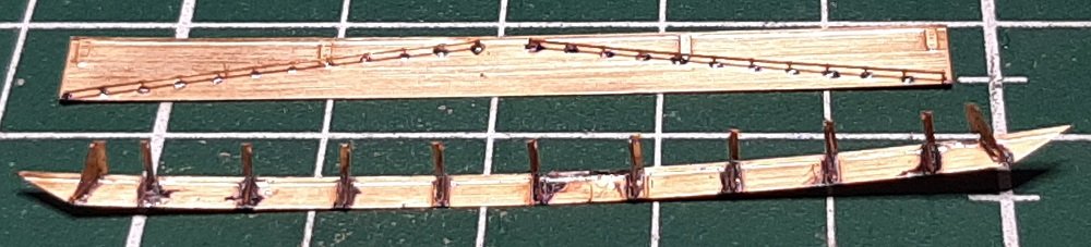
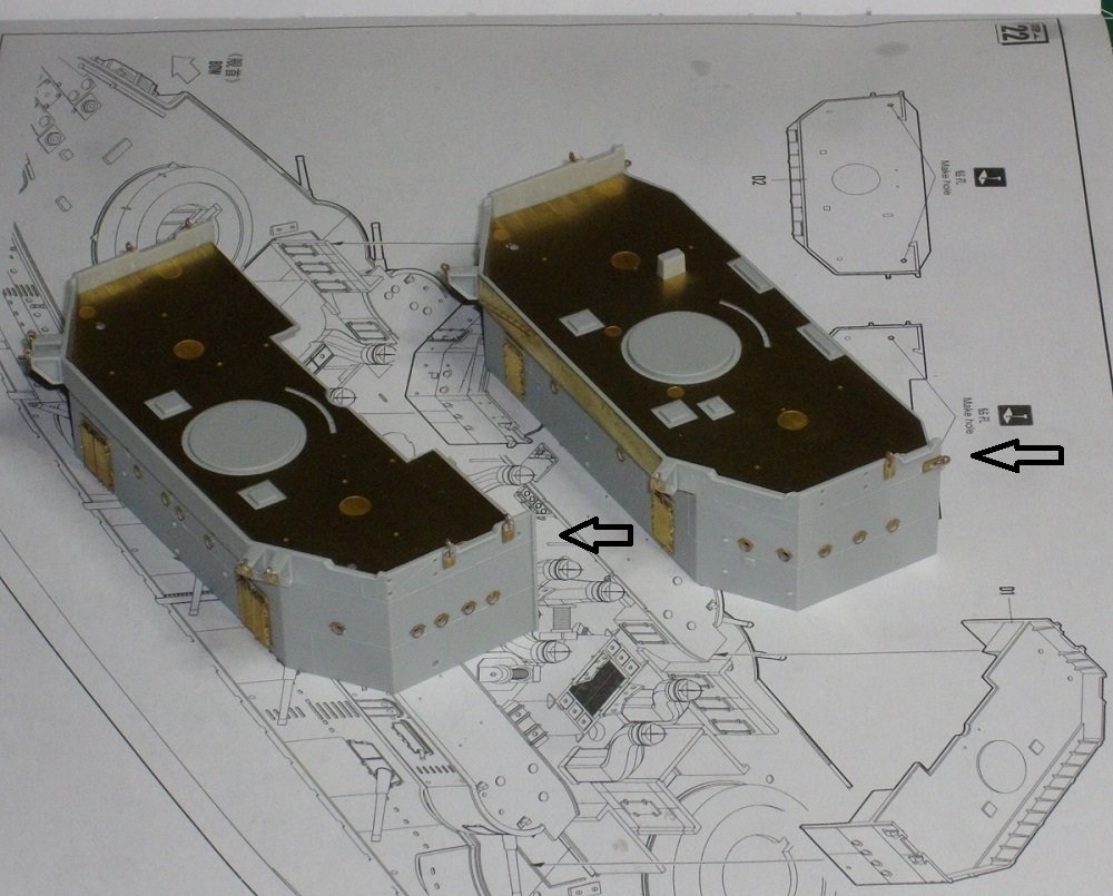
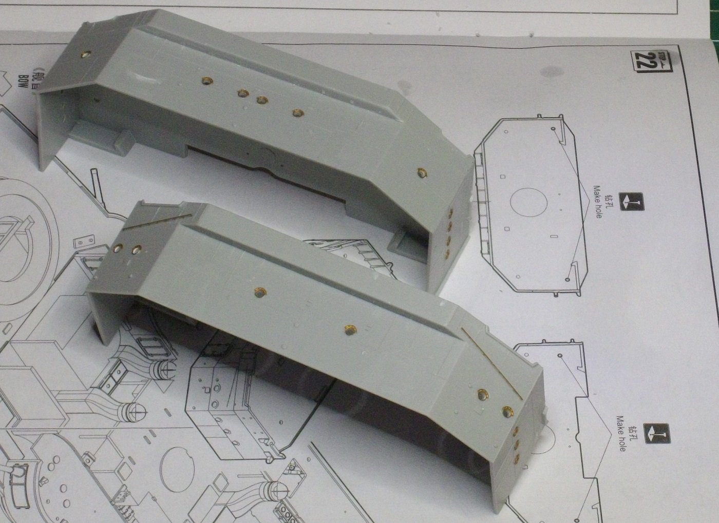
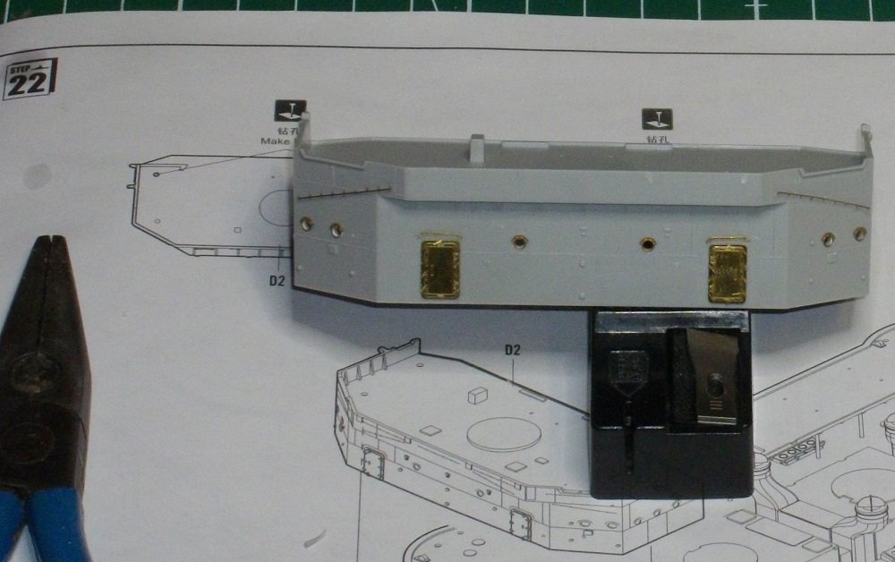
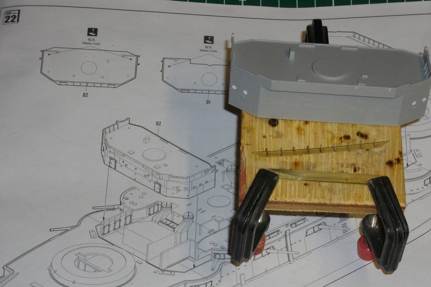
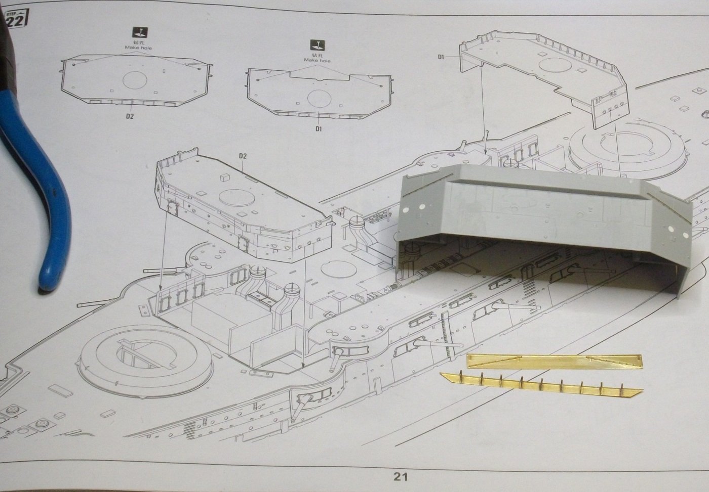
Steps 20/21: boat decks.
I removed the protruding datails of the Merit parts as I did ont the main deck.
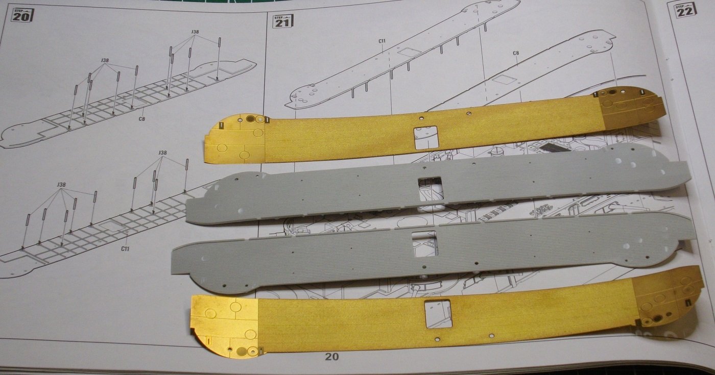
Then I soldered rigging brachets and boat supports to the baseplates,
and finaly used 5 minutes epoxy to glue the brass plates to the plastic base.
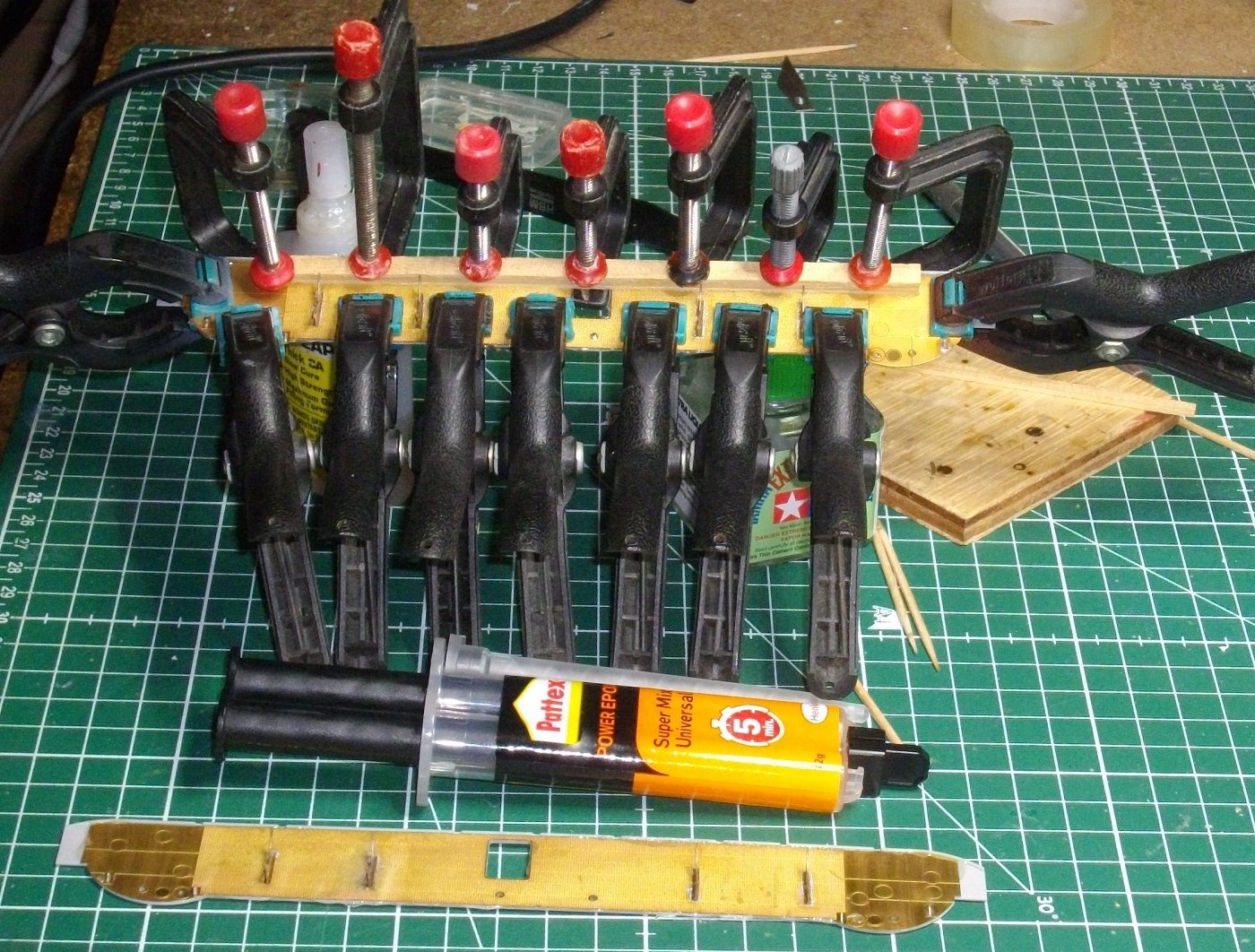
After curing, I cut the excess glue off.
Till next update, enjoy modelling.
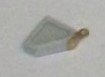
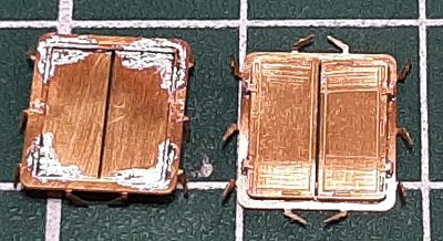
-
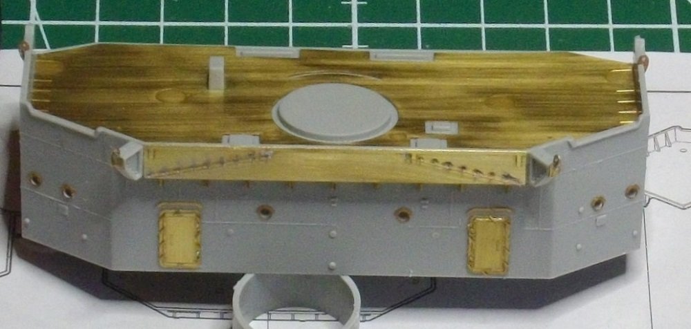
Browsing through the manuals I came across the following part for the midsection of the main deck.
Pontos parts 29, 352 and 2x 353 are soldered together with a little soldering paste and heat applied from the back.
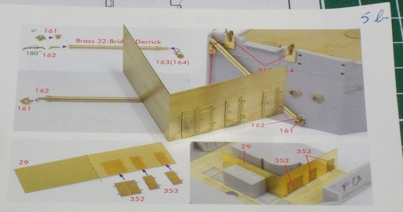
Till next update, enjoy modelling.
- yvesvidal, GrandpaPhil, ccoyle and 3 others
-
6


IJN Mikasa by Herby63 - Merit International with Pontos set - 1/200 - PLASTIC
in - Kit build logs for subjects built from 1901 - Present Day
Posted
Time to lay down the boatdecks, so I glued the little plastic pilars with Tamiya extra thin cement, and lined them up with the holes in the wooden deck.
When this was dry, I glued the boatdecks on the bulkheads witg Revell Contacta professional and the necessary clamps.
Untill next update, enjoy modelling.