
FreekS
-
Posts
240 -
Joined
-
Last visited


-
 NavyShooter reacted to a post in a topic:
MV/HMNLS Macoma 1935/1942 by FreekS - 1:144 - 3D-print - RADIO
NavyShooter reacted to a post in a topic:
MV/HMNLS Macoma 1935/1942 by FreekS - 1:144 - 3D-print - RADIO
-
ccoyle reacted to a post in a topic:
MV/HMNLS Macoma 1935/1942 by FreekS - 1:144 - 3D-print - RADIO
-
Canute reacted to a post in a topic:
MV/HMNLS Macoma 1935/1942 by FreekS - 1:144 - 3D-print - RADIO
-
yvesvidal reacted to a post in a topic:
MV/HMNLS Macoma 1935/1942 by FreekS - 1:144 - 3D-print - RADIO
-
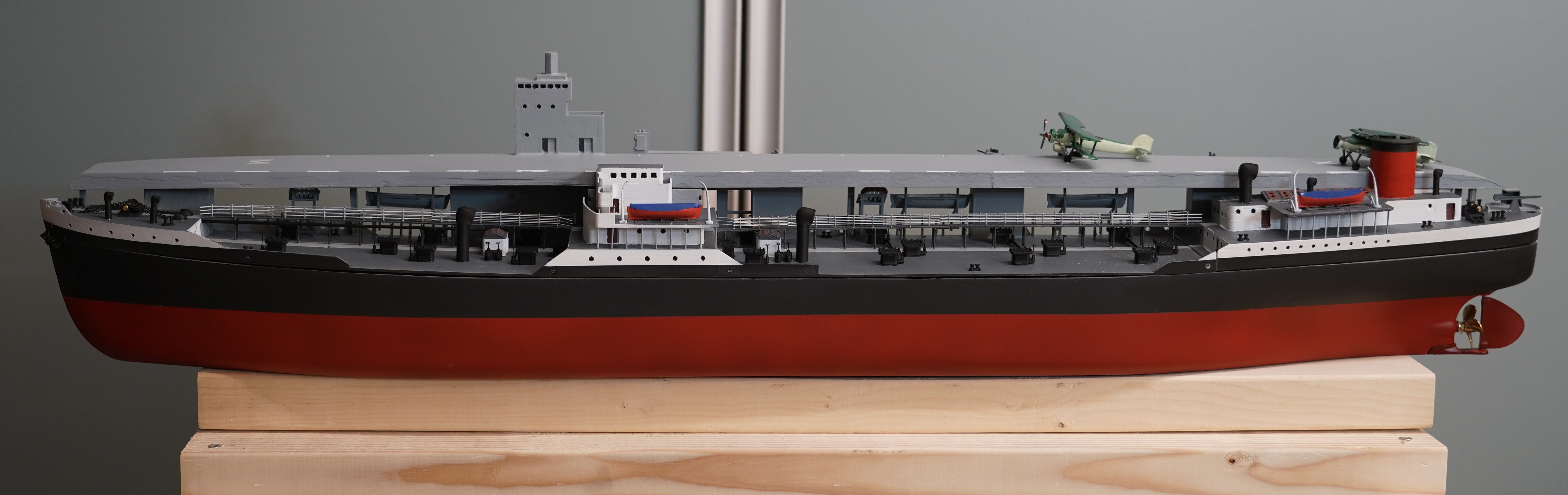
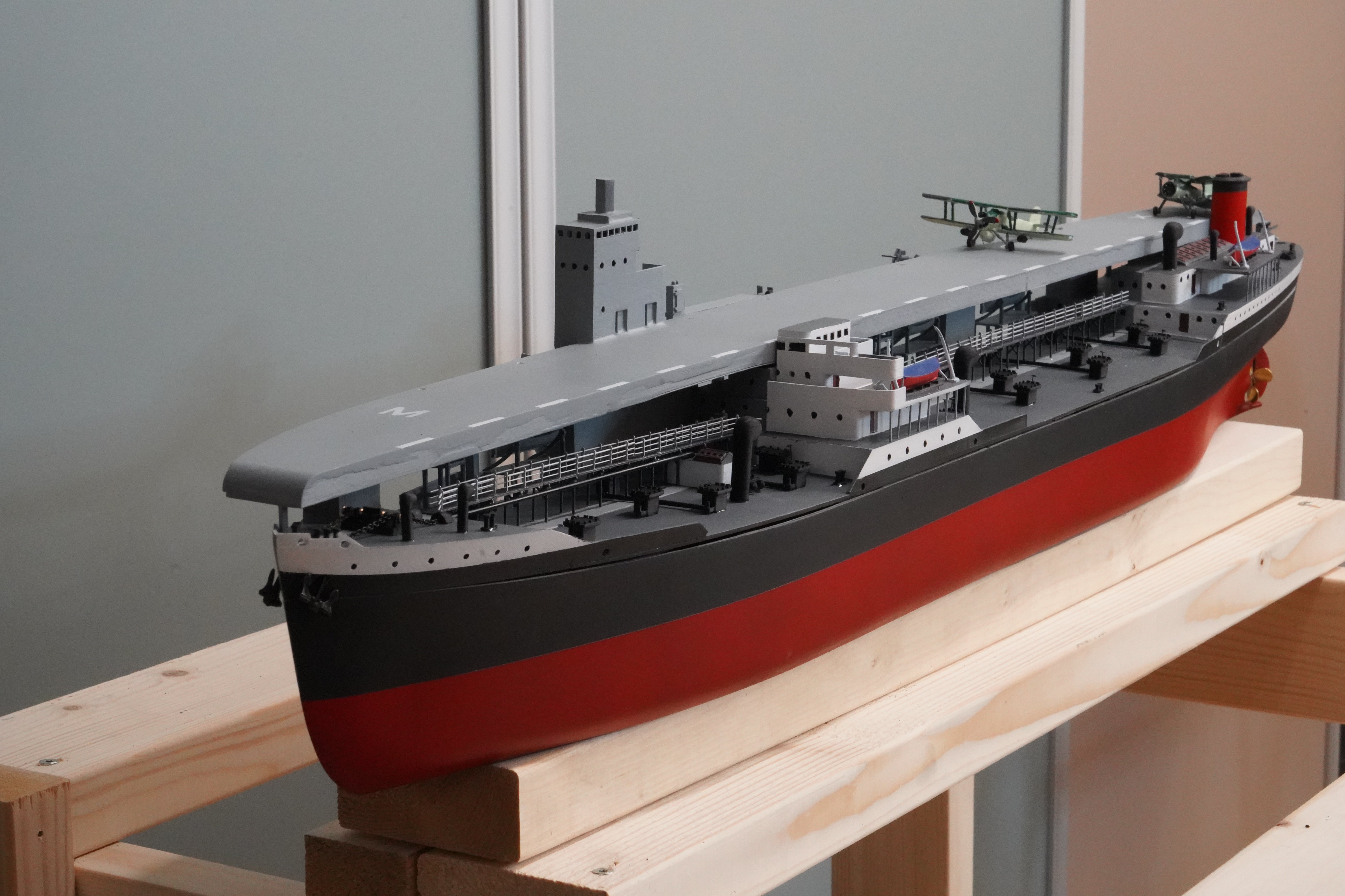
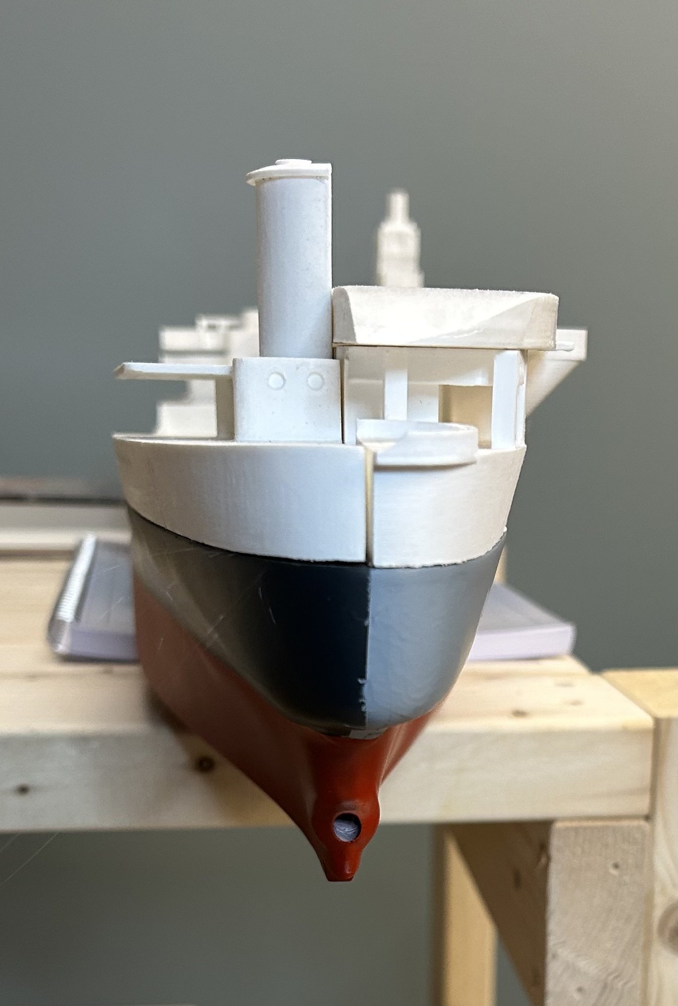
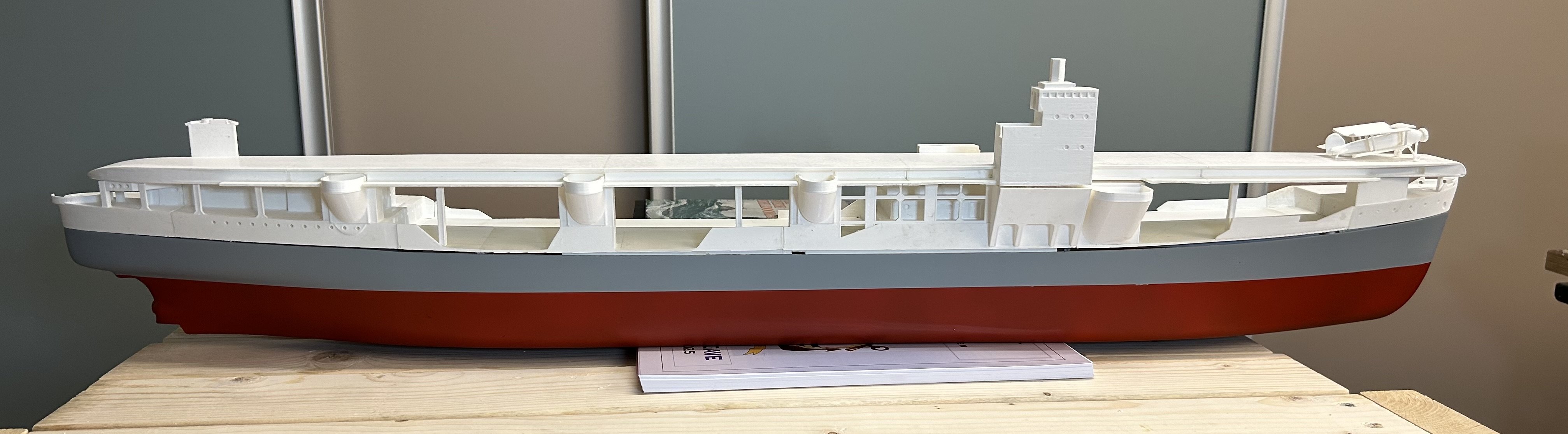
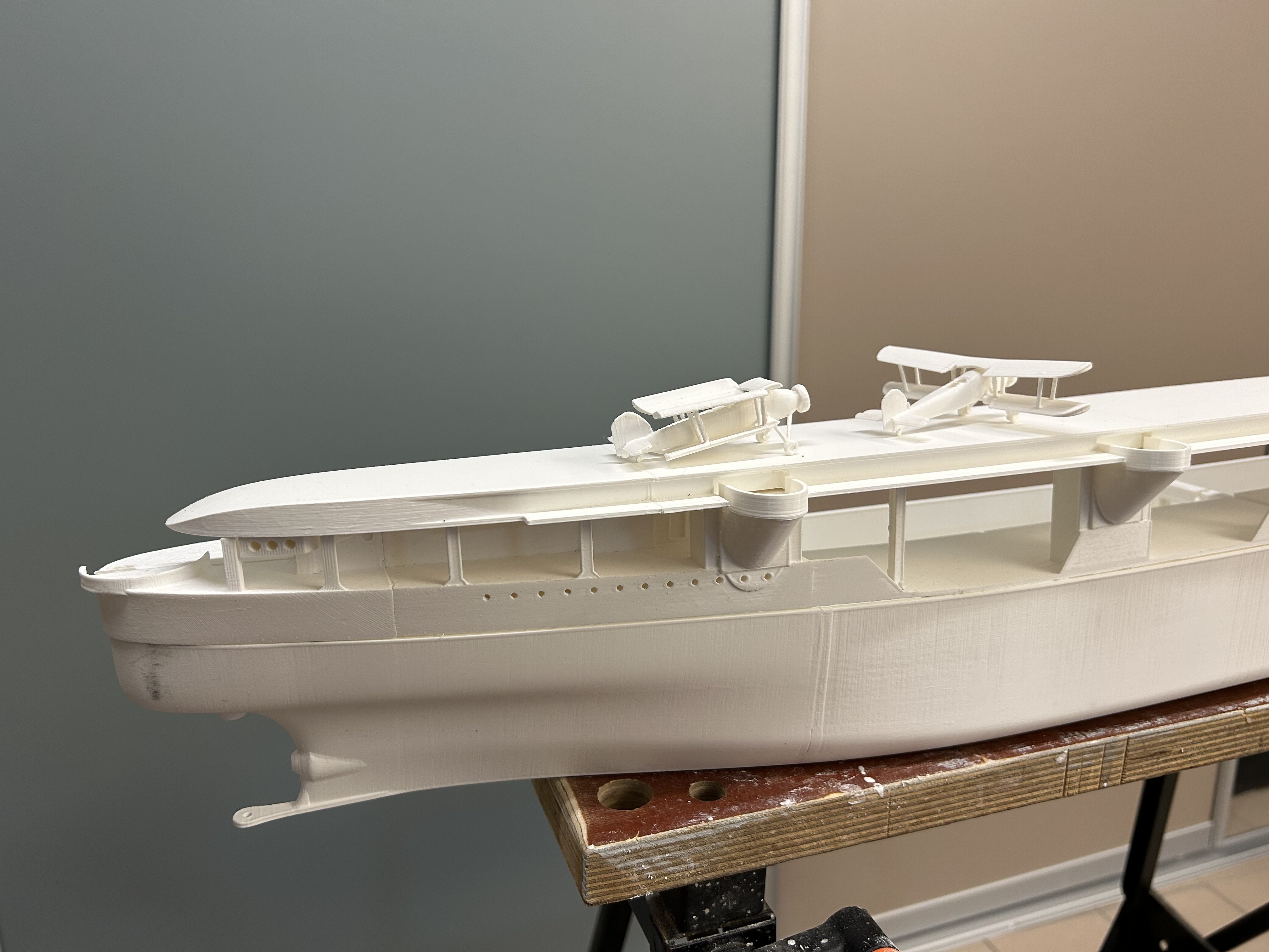
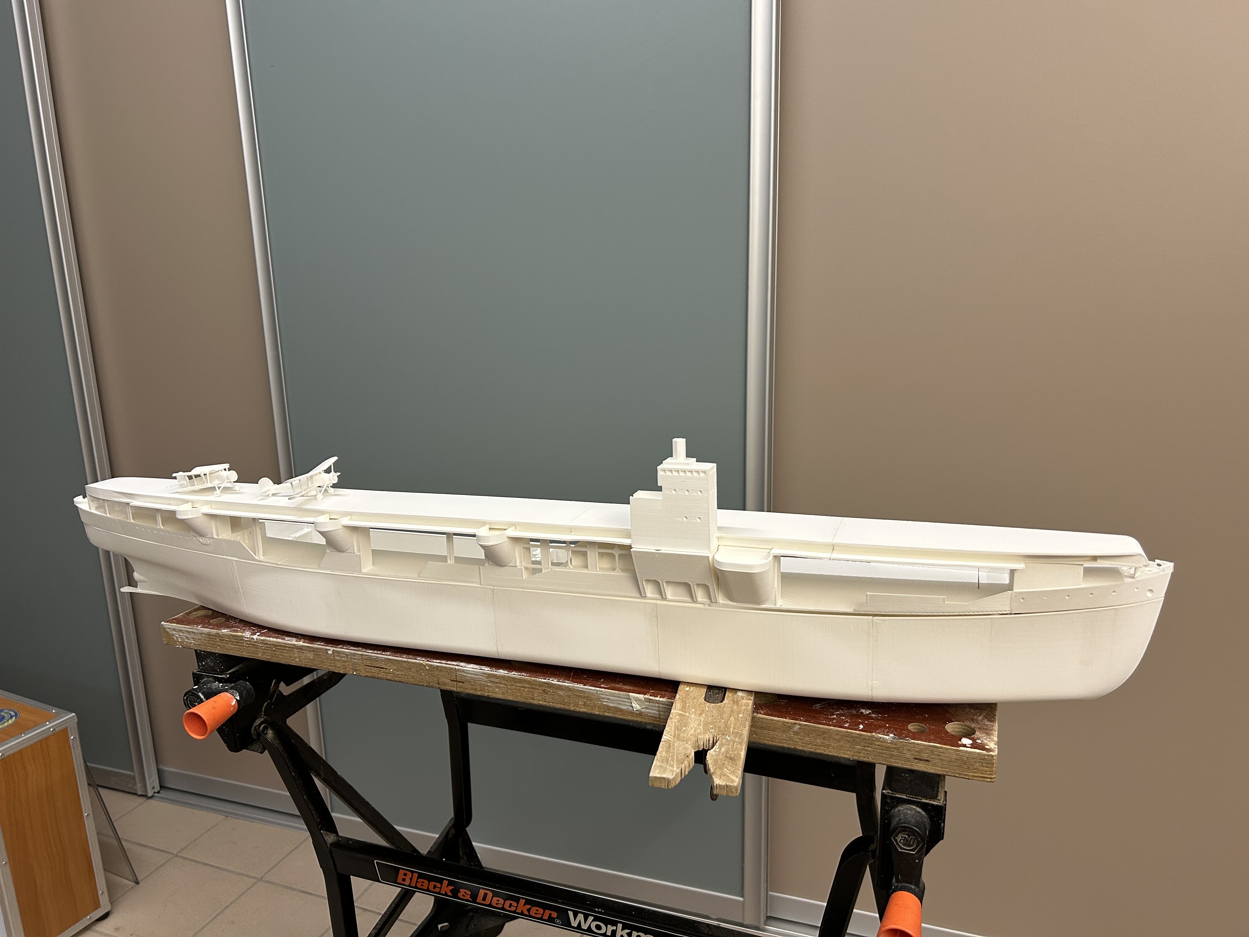
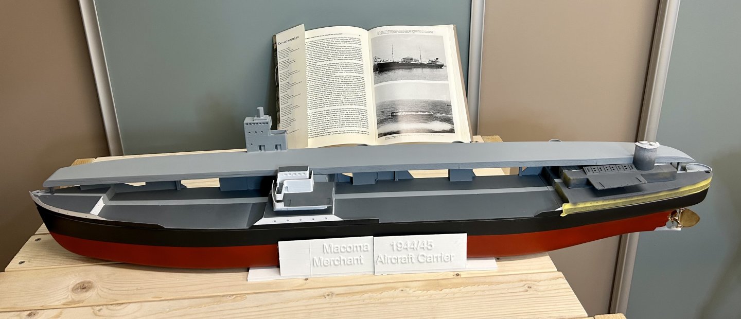
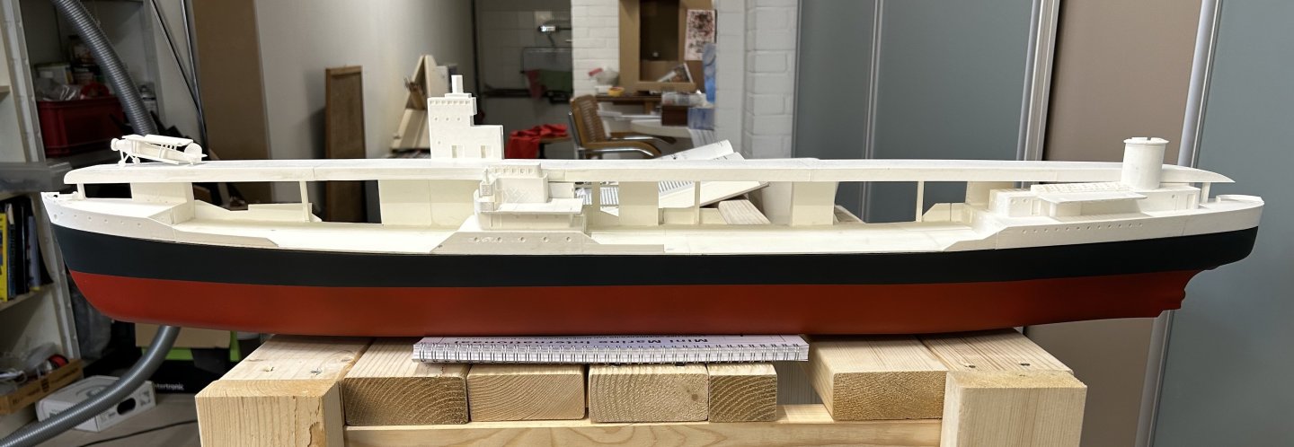
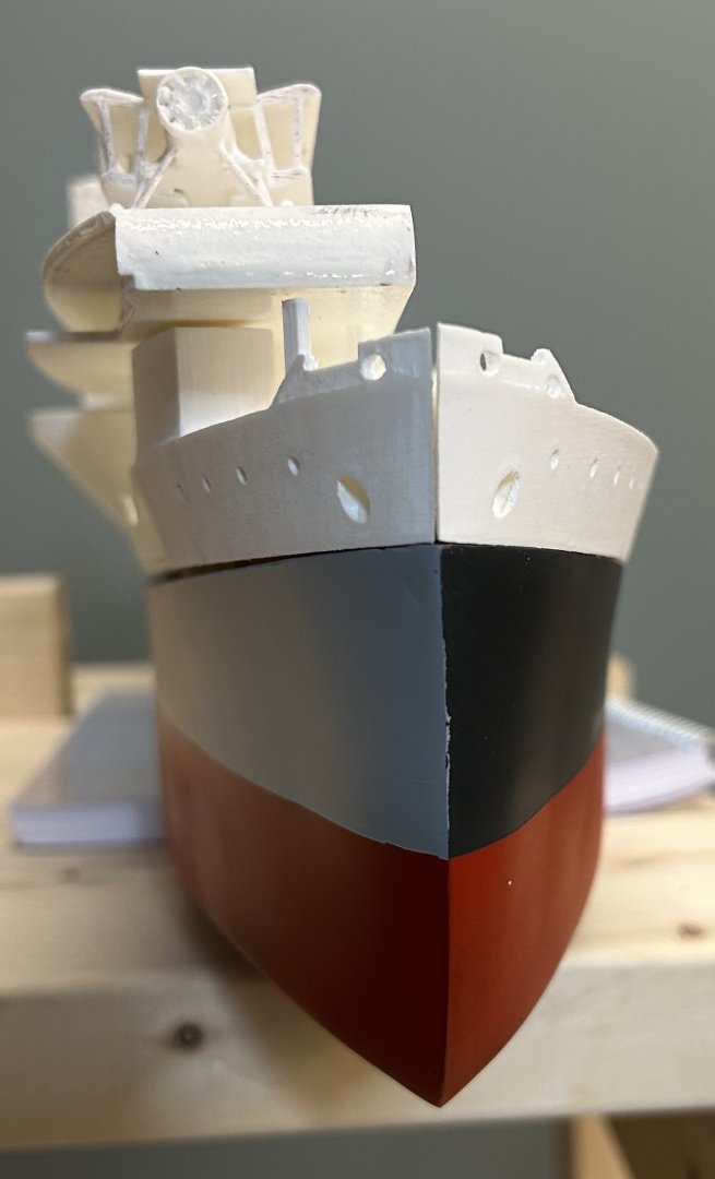
Past few weeks have been mainly about painting and mounting the various smaller parts. The Swordfish’ have been painted and are shown in their intended positions on the (half)deck. On the tanker side the oil handling facilities, winches, walkways and lifeboats have been mounted. The differences in colour between the tanker nd carrier sides is starting to work for me. I’m waiting with the railings and masts until I’ve done the RC stuff inside and finalised the ballast, after which the front part of the deck can be glued. and here a photo from the front


-
FreekS reacted to a post in a topic:
Chaconia by Javelin - 1/100 - RADIO - LPG Tanker
-
FreekS reacted to a post in a topic:
USS Cape (MSI-2) by Dr PR - 1:48 - Inshore Minesweeper
-
FreekS reacted to a post in a topic:
Herzogin Cecilie 1902 by Jim Lad - Four Masted Barque
-
FreekS reacted to a post in a topic:
Type 26 City-Class frigate by NavyShooter - 3D Print - 1/144 - Display
-
FreekS reacted to a post in a topic:
Type 26 City-Class frigate by NavyShooter - 3D Print - 1/144 - Display
-
Canute reacted to a post in a topic:
MV/HMNLS Macoma 1935/1942 by FreekS - 1:144 - 3D-print - RADIO
-
Jim Lad reacted to a post in a topic:
MV/HMNLS Macoma 1935/1942 by FreekS - 1:144 - 3D-print - RADIO
-
FreekS reacted to a post in a topic:
Type 26 City-Class frigate by NavyShooter - 3D Print - 1/144 - Display
-
 yvesvidal reacted to a post in a topic:
MV/HMNLS Macoma 1935/1942 by FreekS - 1:144 - 3D-print - RADIO
yvesvidal reacted to a post in a topic:
MV/HMNLS Macoma 1935/1942 by FreekS - 1:144 - 3D-print - RADIO
-
ccoyle reacted to a post in a topic:
MV/HMNLS Macoma 1935/1942 by FreekS - 1:144 - 3D-print - RADIO
-
NavyShooter reacted to a post in a topic:
MV/HMNLS Macoma 1935/1942 by FreekS - 1:144 - 3D-print - RADIO
-
NavyShooter reacted to a post in a topic:
MV/HMNLS Macoma 1935/1942 by FreekS - 1:144 - 3D-print - RADIO
-
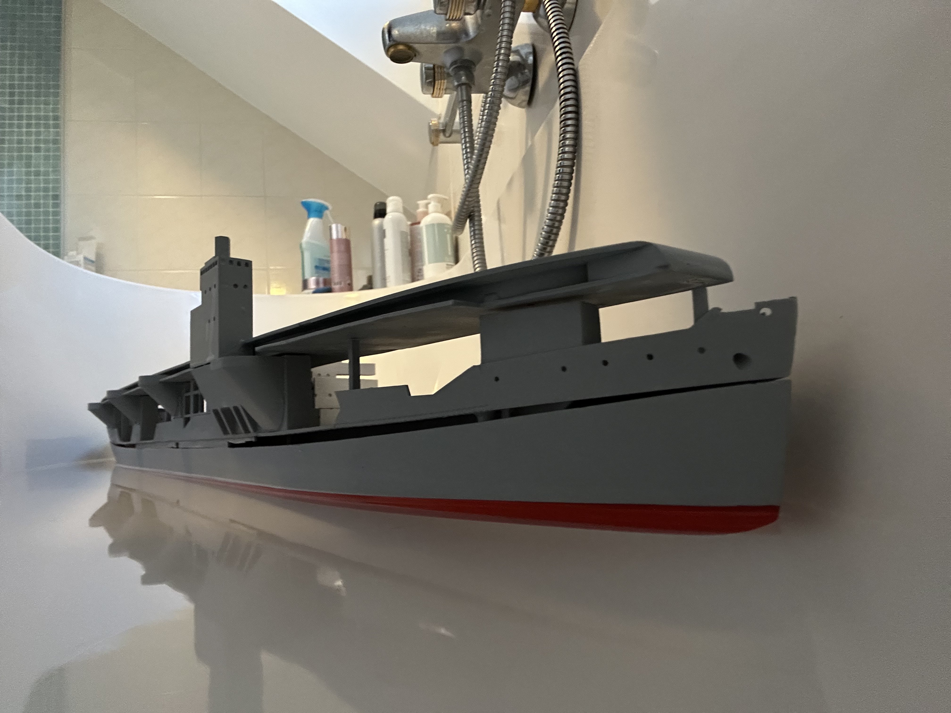
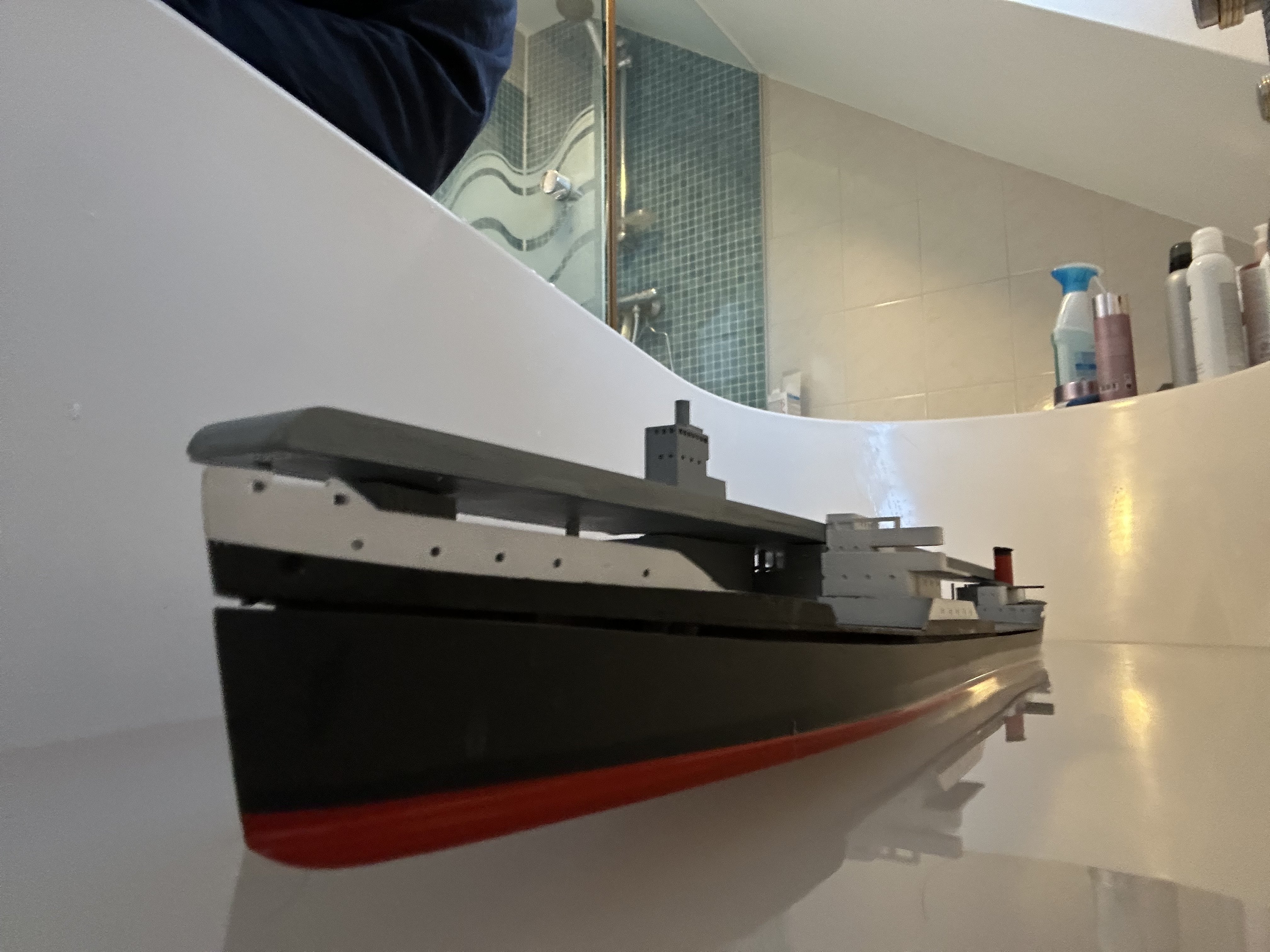
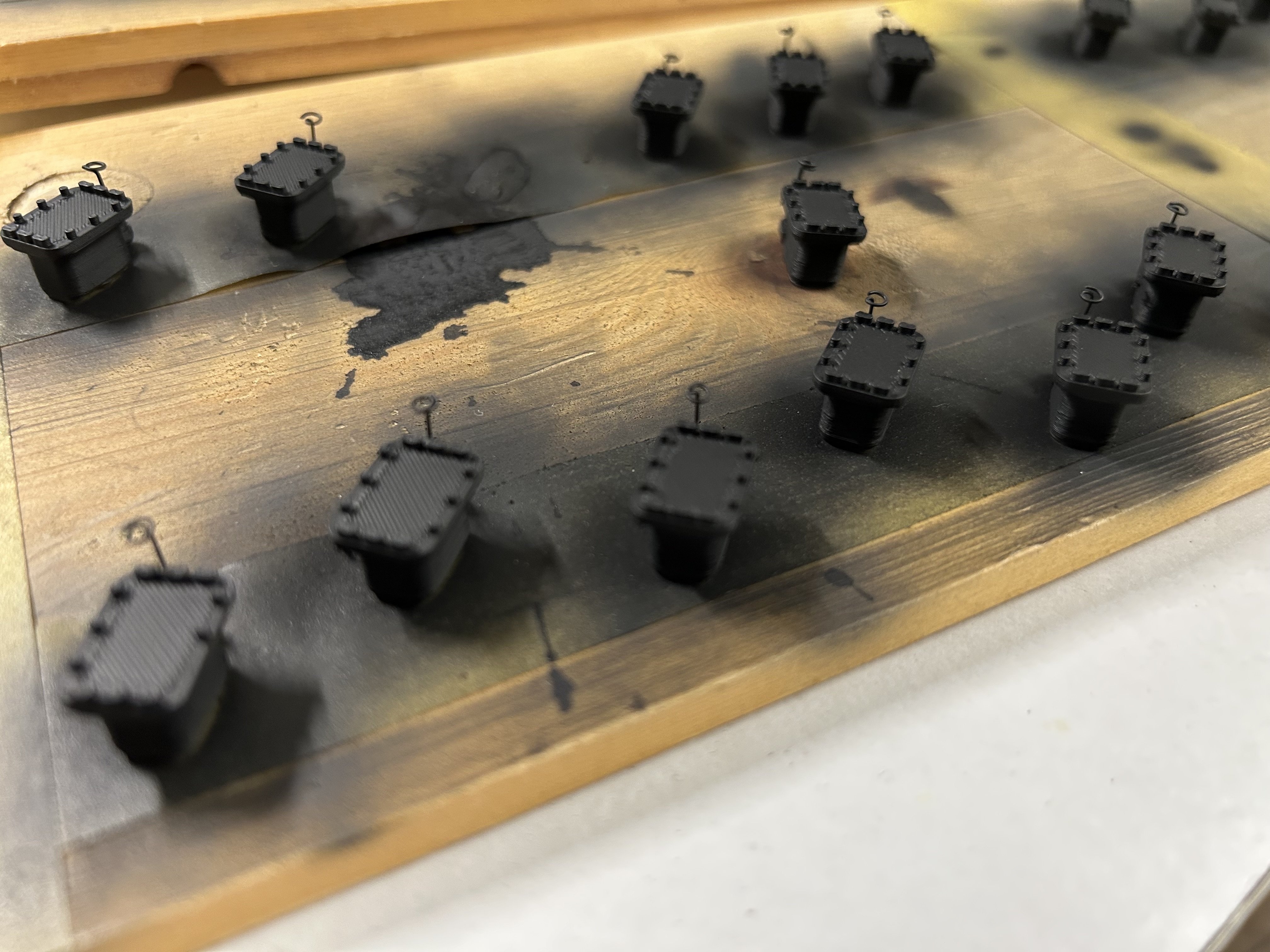
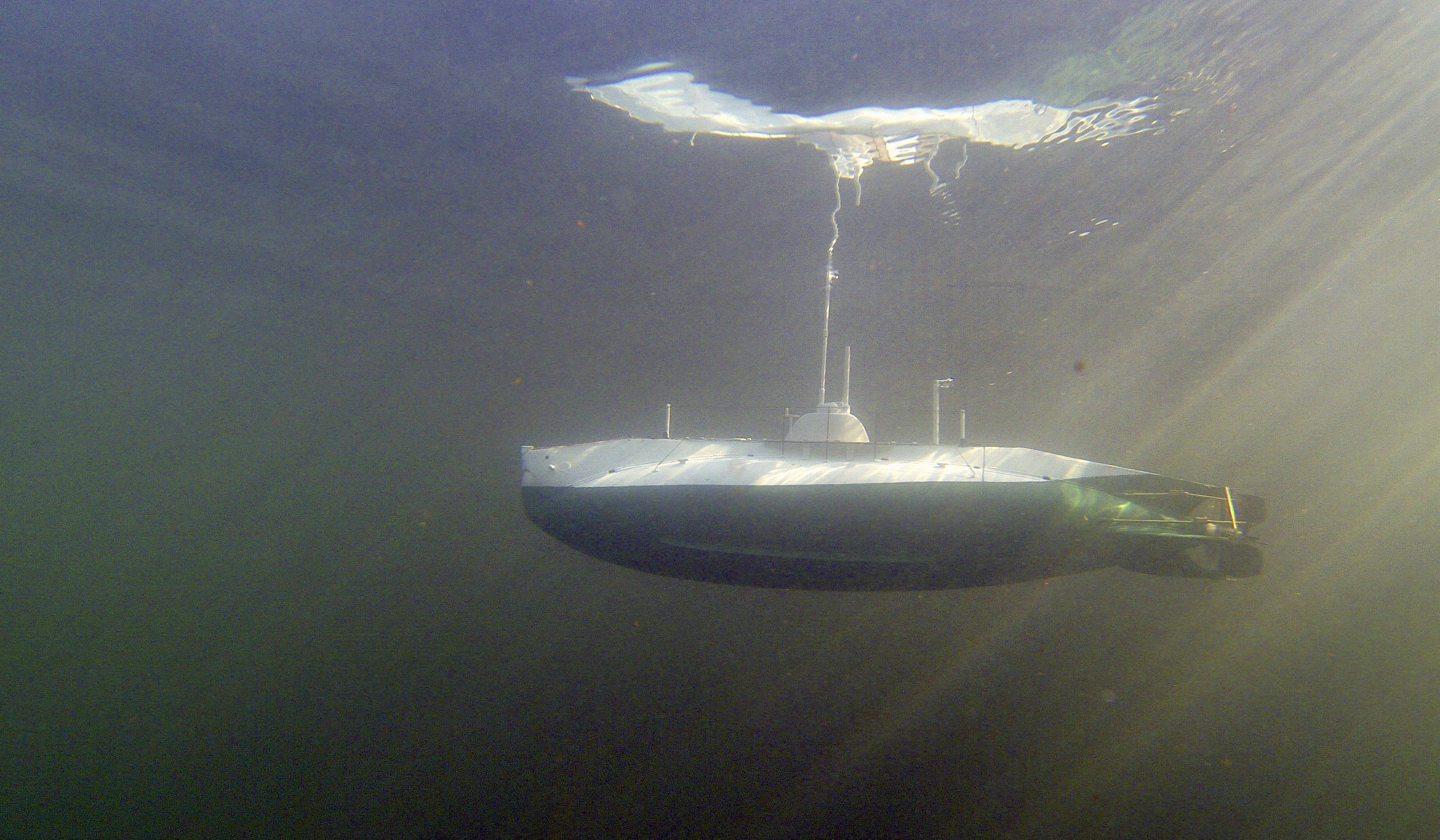
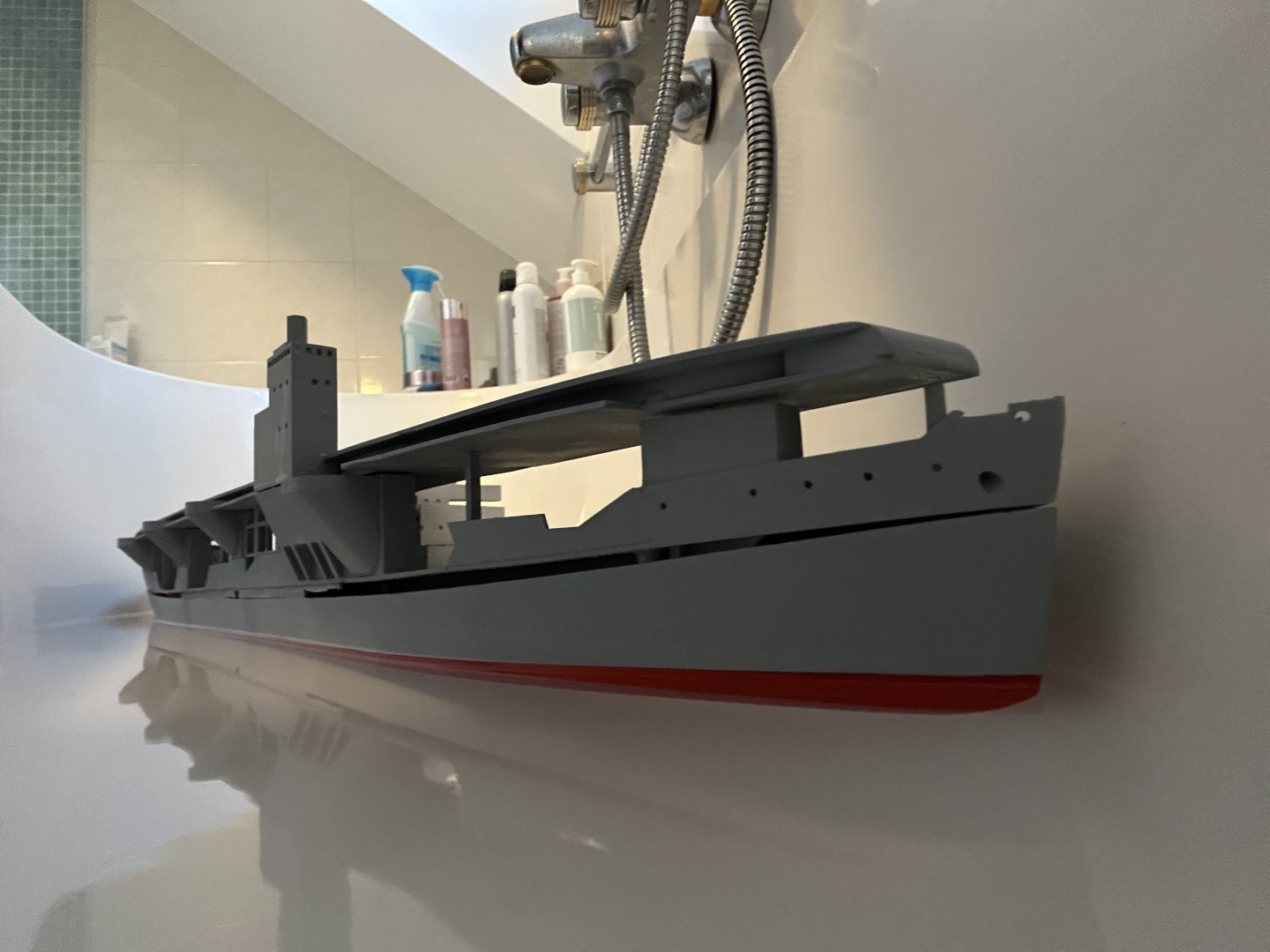
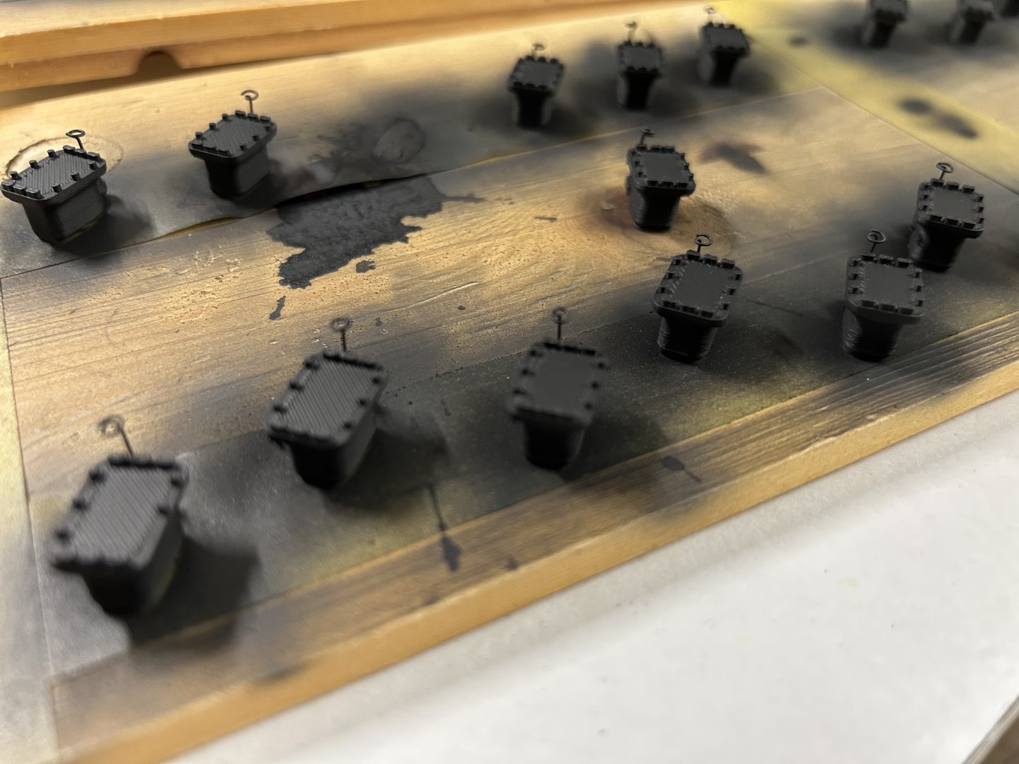
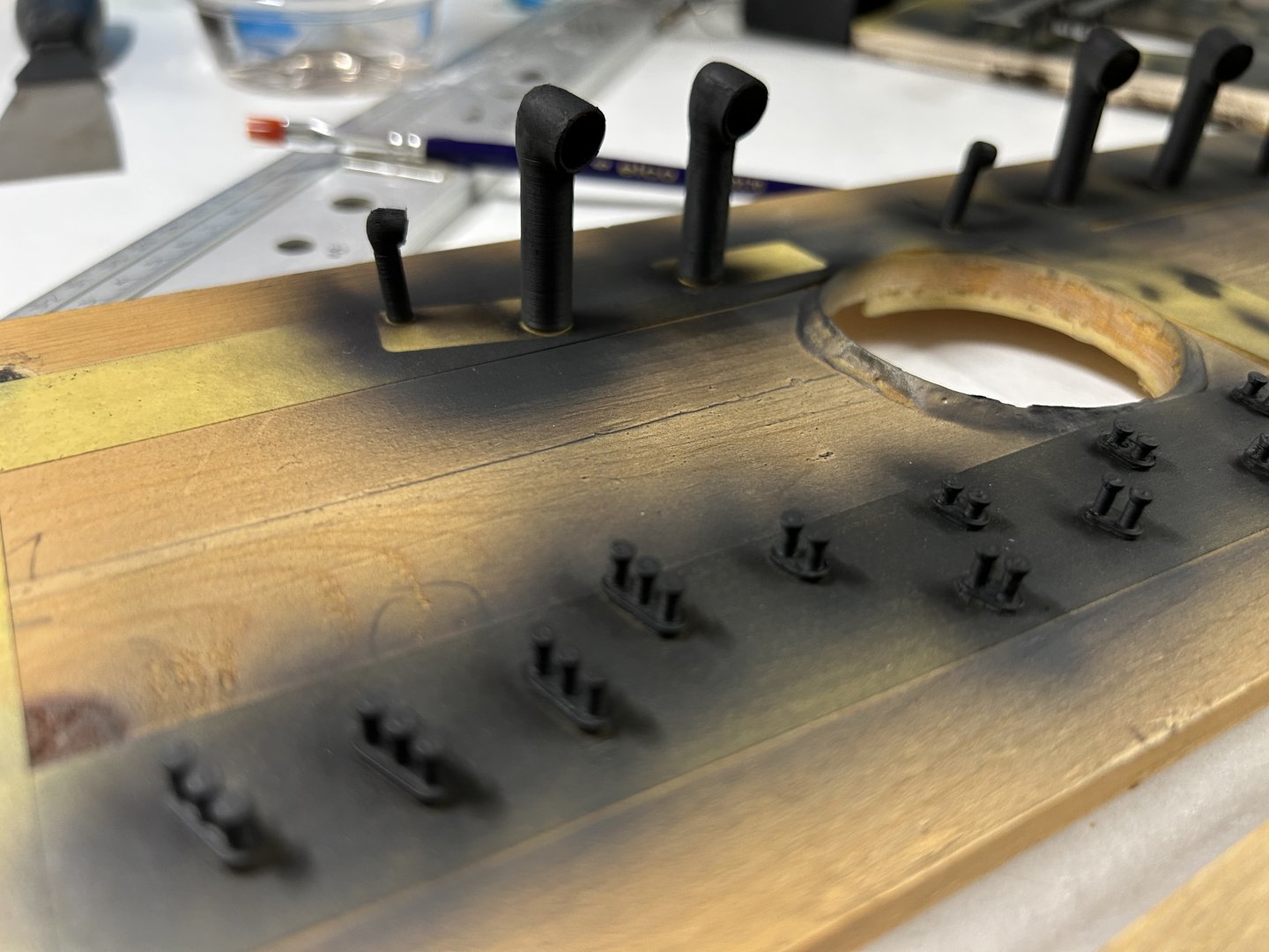
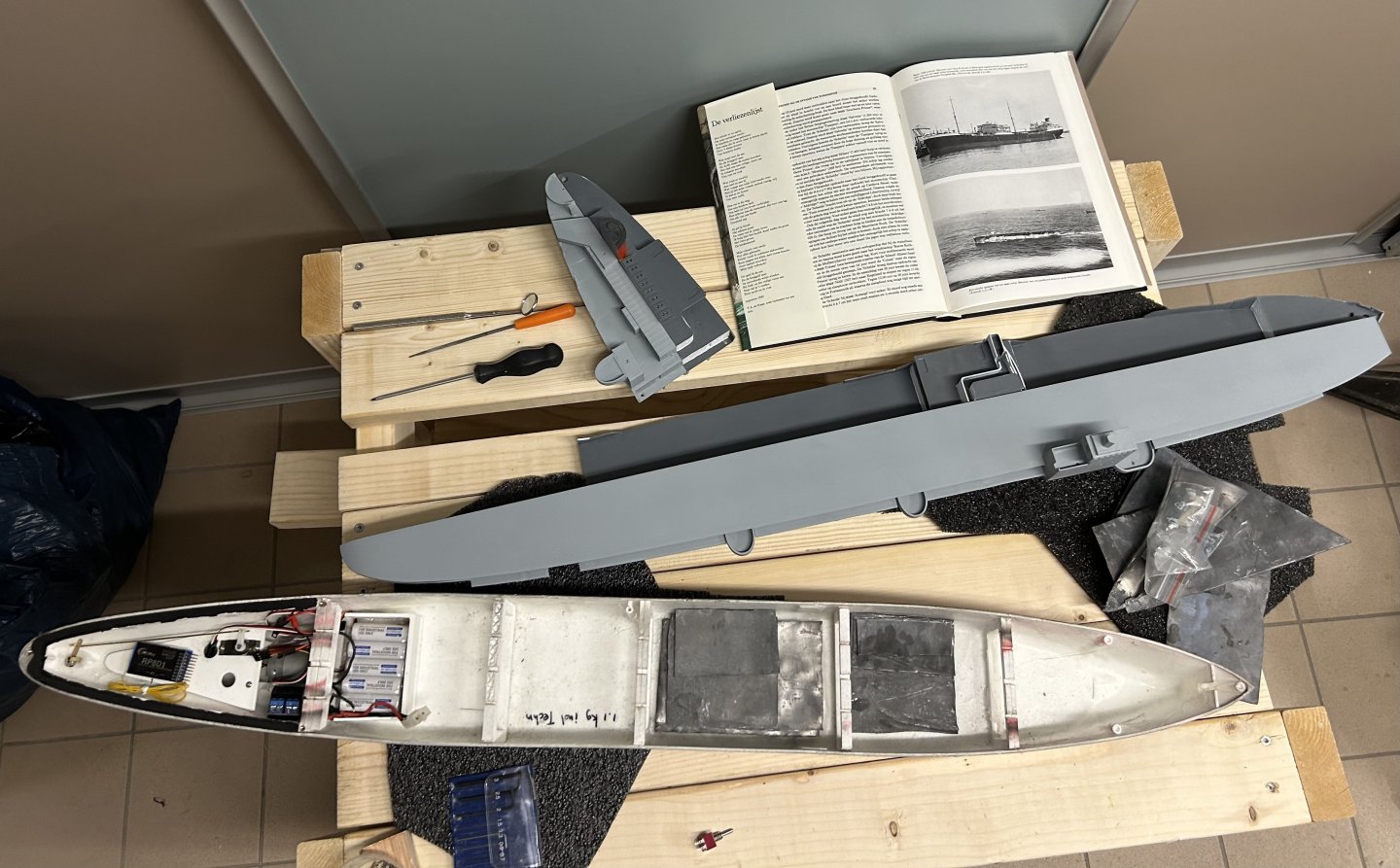
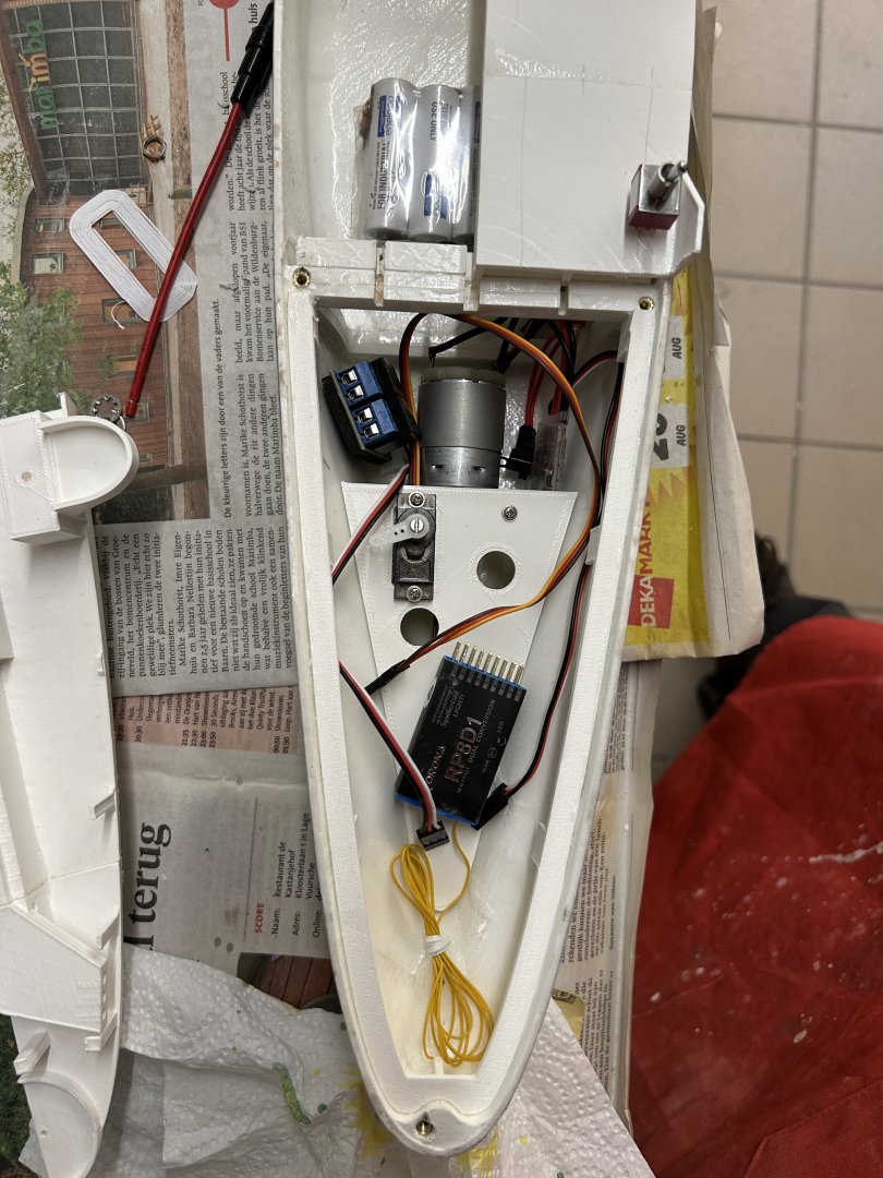
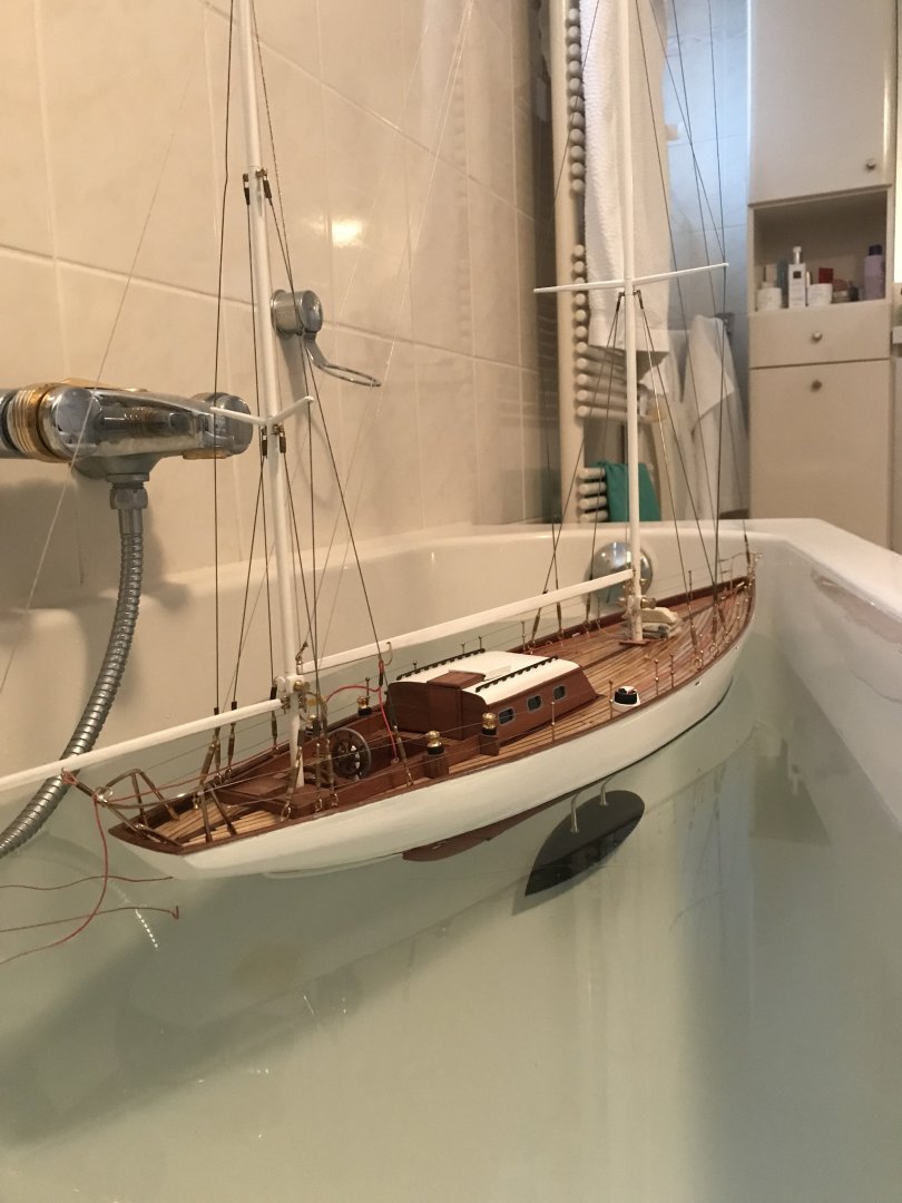
Today I started ballasting the ship, the basic equipment such as motor and battery are in, and the ship required 1,5 kg of lead to reach the waterline. Total weight 3,6 kg. The ship is still a little unstable (roll), but that was true for the original also with the high flight deck. I’ll be glueing the deck to the hull to prevent water ingress. Here two pics from the tanker and carrier sides in my bath. and here the weight distribution inside the ship - some lead is located on the port side to counterbalance the weight of the flight deck on starboard side. Also visible is the seal aft where the aft part of the deck will be removable. also been spray painting 20 manhole access covers to the tanks, guns and lifeboats for the carrier side, and deck accessories - all printed.


-
FreekS reacted to a post in a topic:
Type 26 City-Class frigate by NavyShooter - 3D Print - 1/144 - Display
-
FreekS reacted to a post in a topic:
USS Cape (MSI-2) by Dr PR - 1:48 - Inshore Minesweeper
-
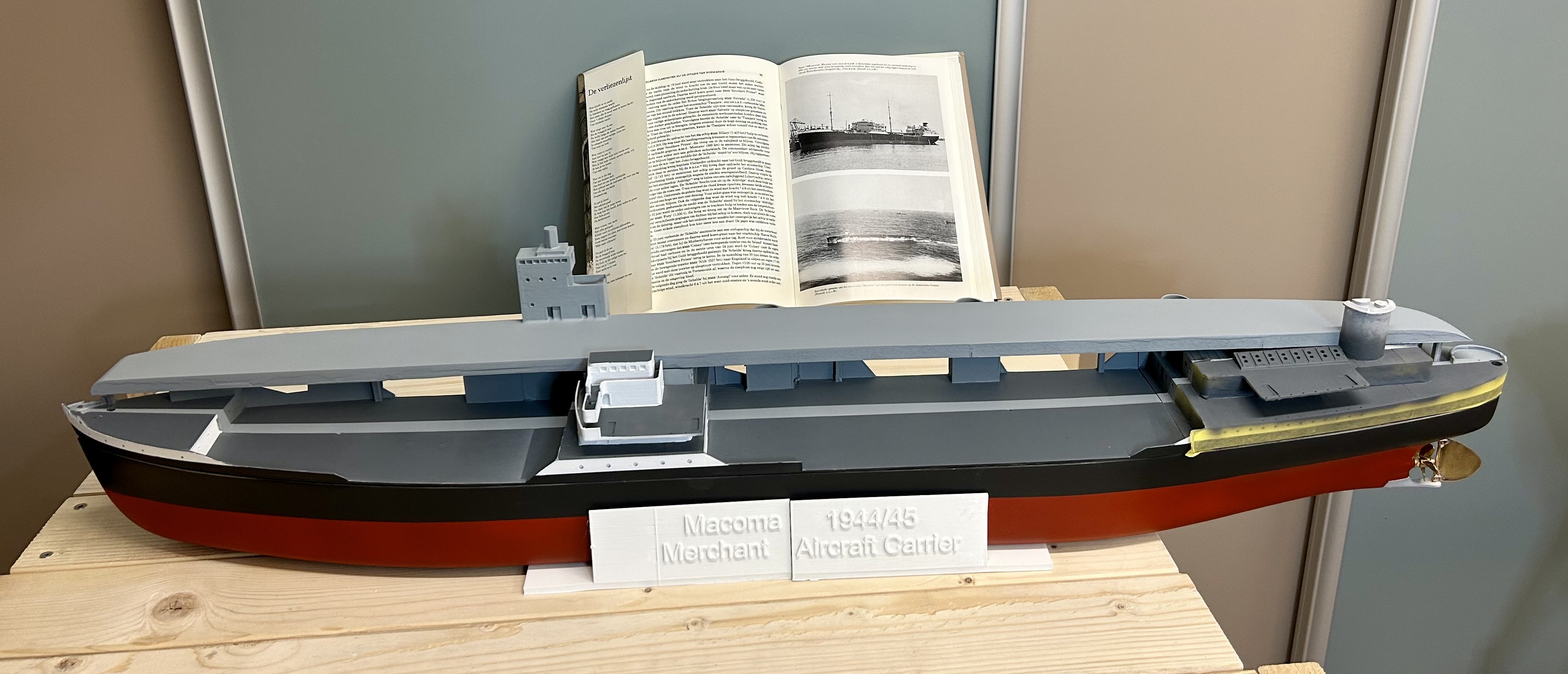
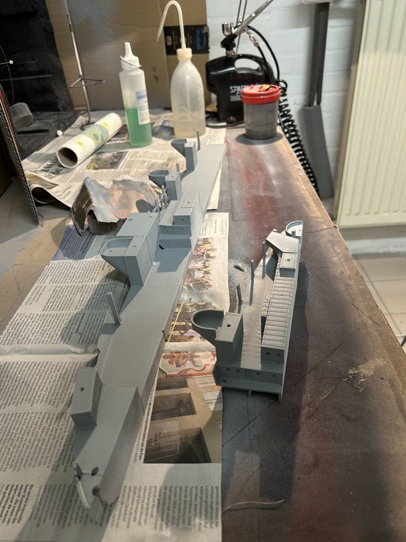
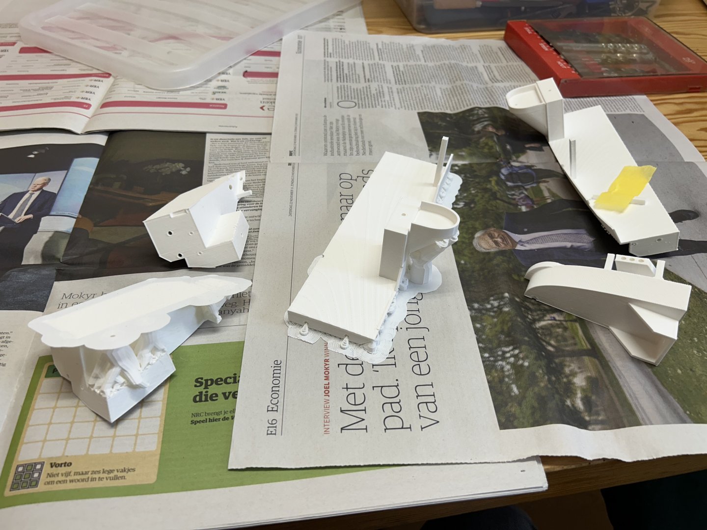
On the weight and balance issues, I cut 2kg of roof-lead into squares - but need to source another kg at least. went further with airbrushing of the main deck sections - with sea-blue- grey for the carrier superstructure, and dark grey for the tanker hull- with white deckhouses and lighter grey decks. This gives some contrast between the two sides so hopefully will lead to two distinct ship halves. Most of the smaller parts are printed and need sanding and painting next. after using a starter set airbrush for 10 years I’ve treated myself to a new compressor with pressure regulator and moisture trap, and a H&S ultra airbrush. More possibilities to optimise - so takes some getting used to… This last pic still has some tape on the white aft deckhouse as parts need another coat, and the tanker and carrier decks are not fitted together yet - hence the light grey centre stripe that will disappear later. Also I cut up two kg of lead into squares as ballast, but need to source some more…

-
I was firmly in the chaff, I went for catalysis as its closest to alchemie - no-one can second guess it!
- 492 replies
-
- 1
-
-
- minesweeper
- Cape
- (and 1 more)
-
FreekS reacted to a post in a topic:
TWILIGHT 2007-2009 by MAGIC's Craig - Scale 1:16 - RADIO - Pacific Northwest cruising powerboat
-
FreekS reacted to a post in a topic:
Cangarda 1901 by KeithAug - Scale 1:24 - Steam Yacht
-
Interesting enough, this experiment (making soap out of fat) was done in high school chemistry classes! I am a professional “soap” chemist (I developed cleaners), and Valeriy’s method is absolutely sound. But just like when the acetone evaporates leaving a tiny amount of pure fat on brass, when you get caustic soda (NaOH) in your eye even in a small amount, the water evaporates and concentrates up the caustic, damaging your eyes. so by all means use this method, but wear safety glasses and take care with NaOH!!
- 492 replies
-
- 4
-
-
- minesweeper
- Cape
- (and 1 more)
-
I do John, but also the two masts on the tanker are going to look funny to an approaching swordfish. Somehow I want to make sure (probably through colours) that the tanker view dominates from one side and the carrier from the other. Not all issues are solved…..
-
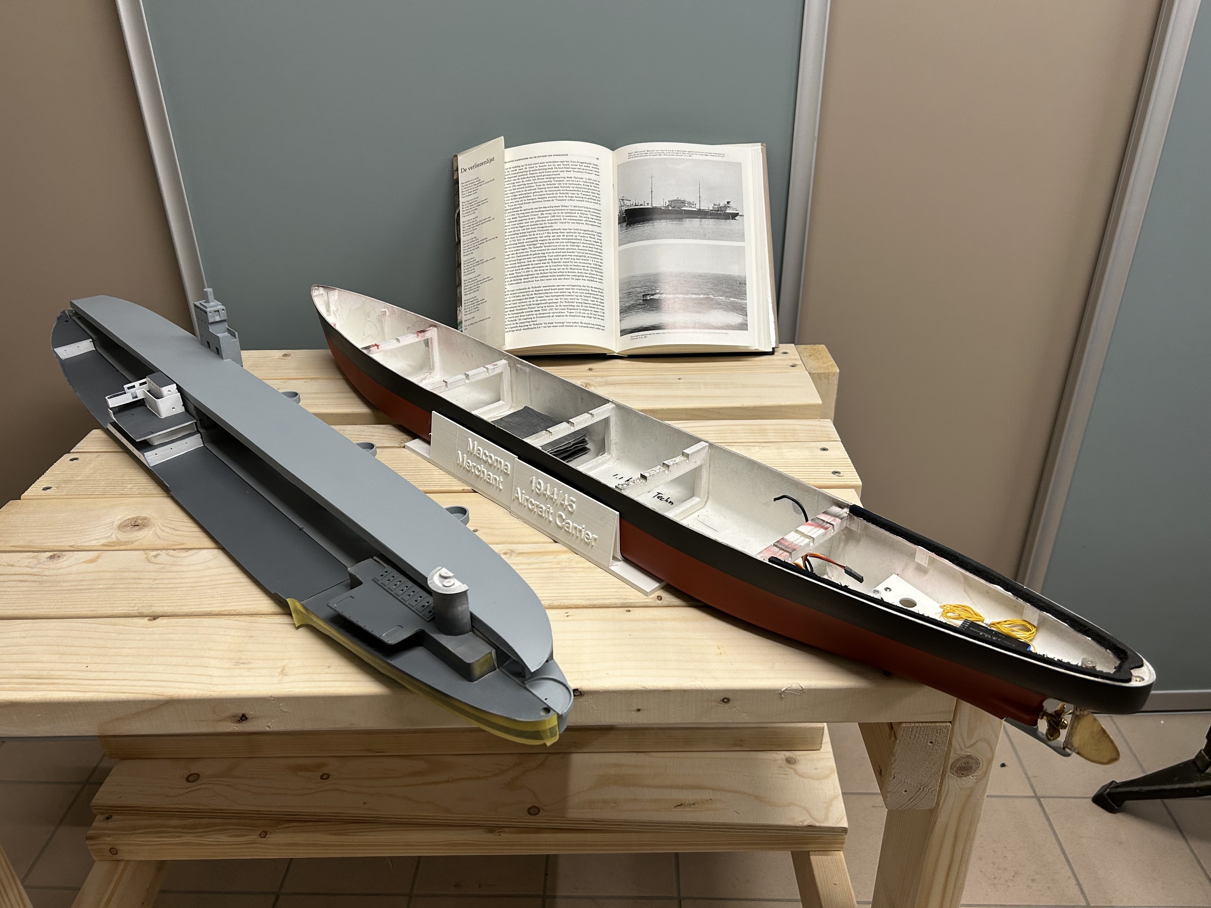
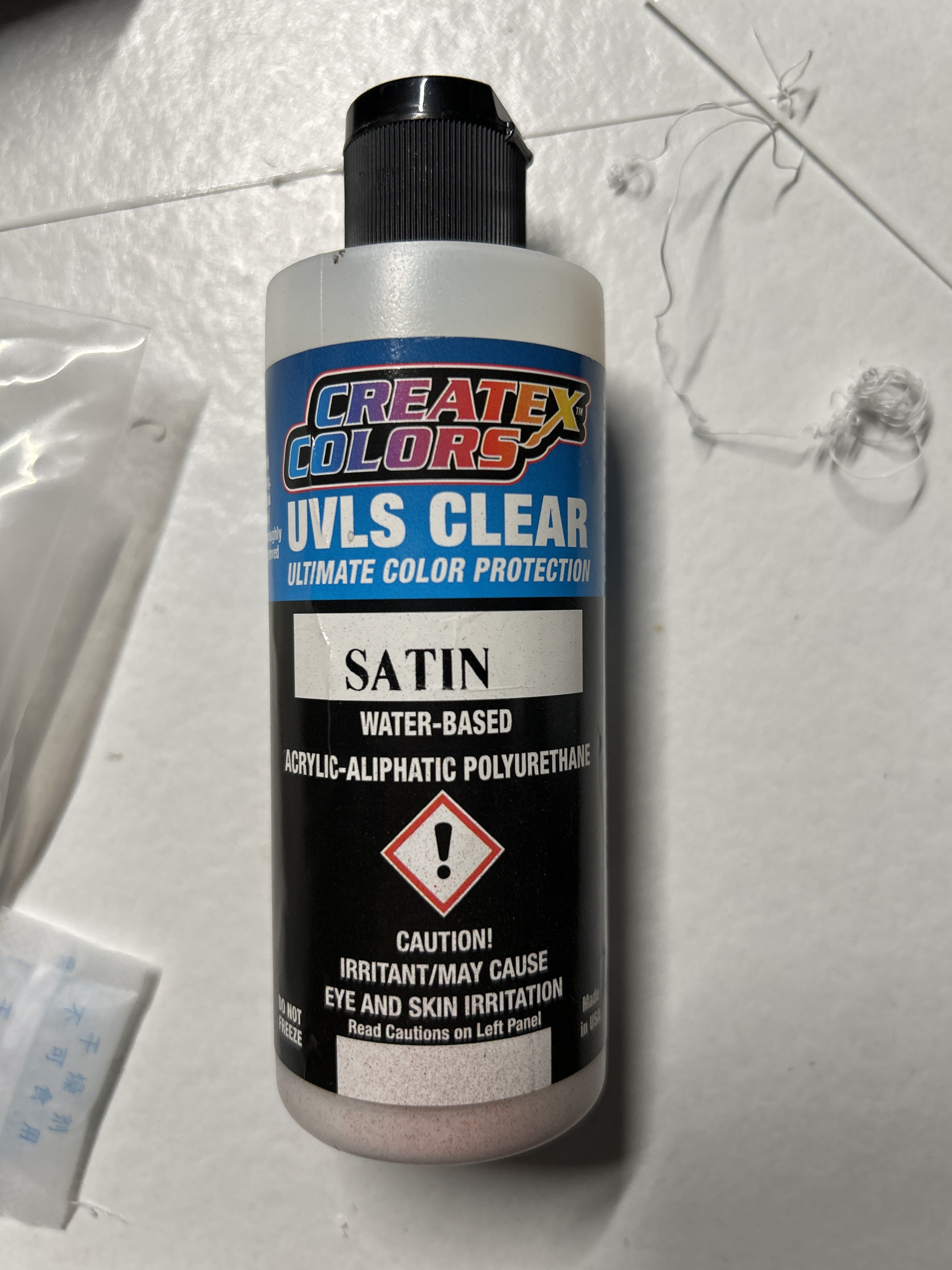
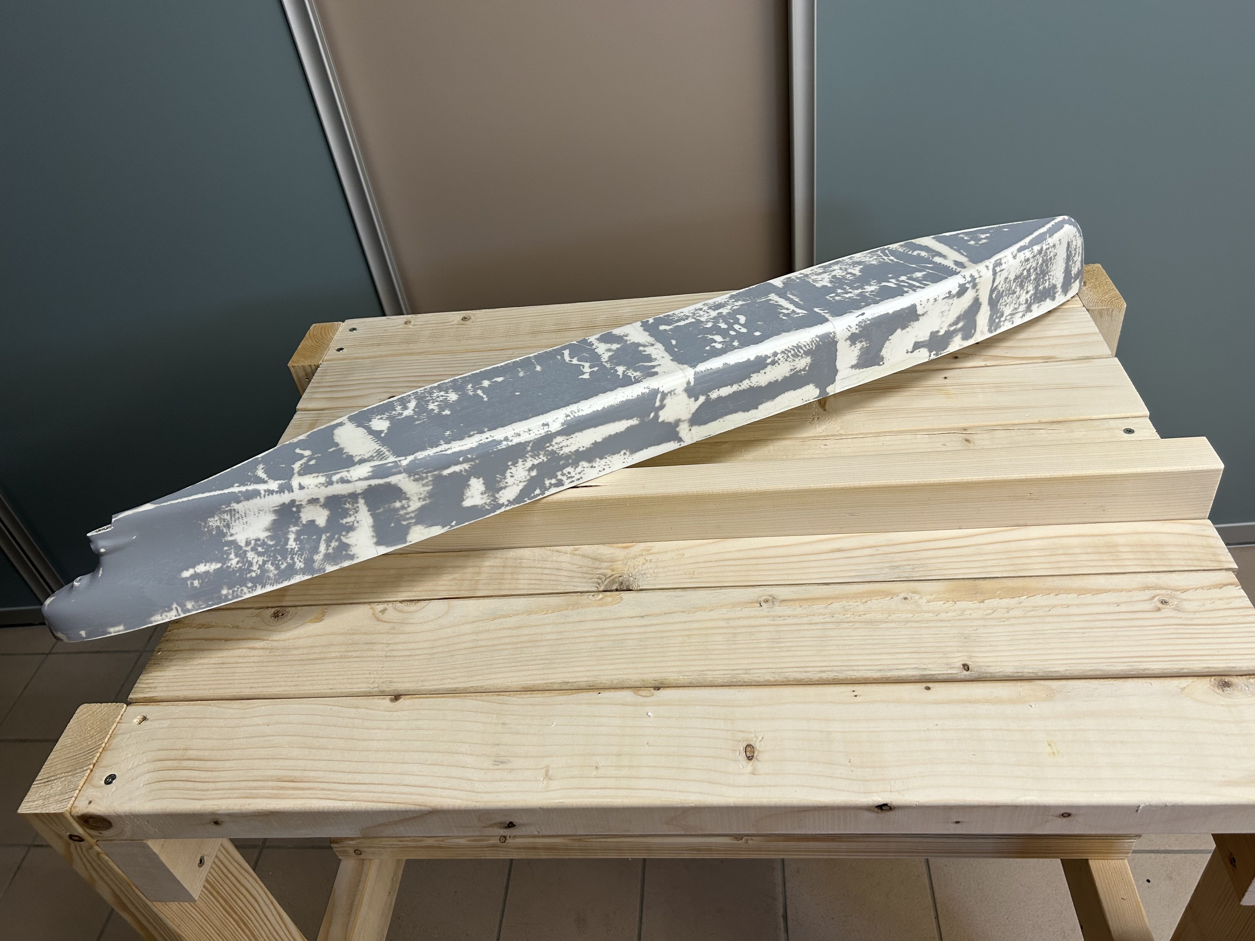
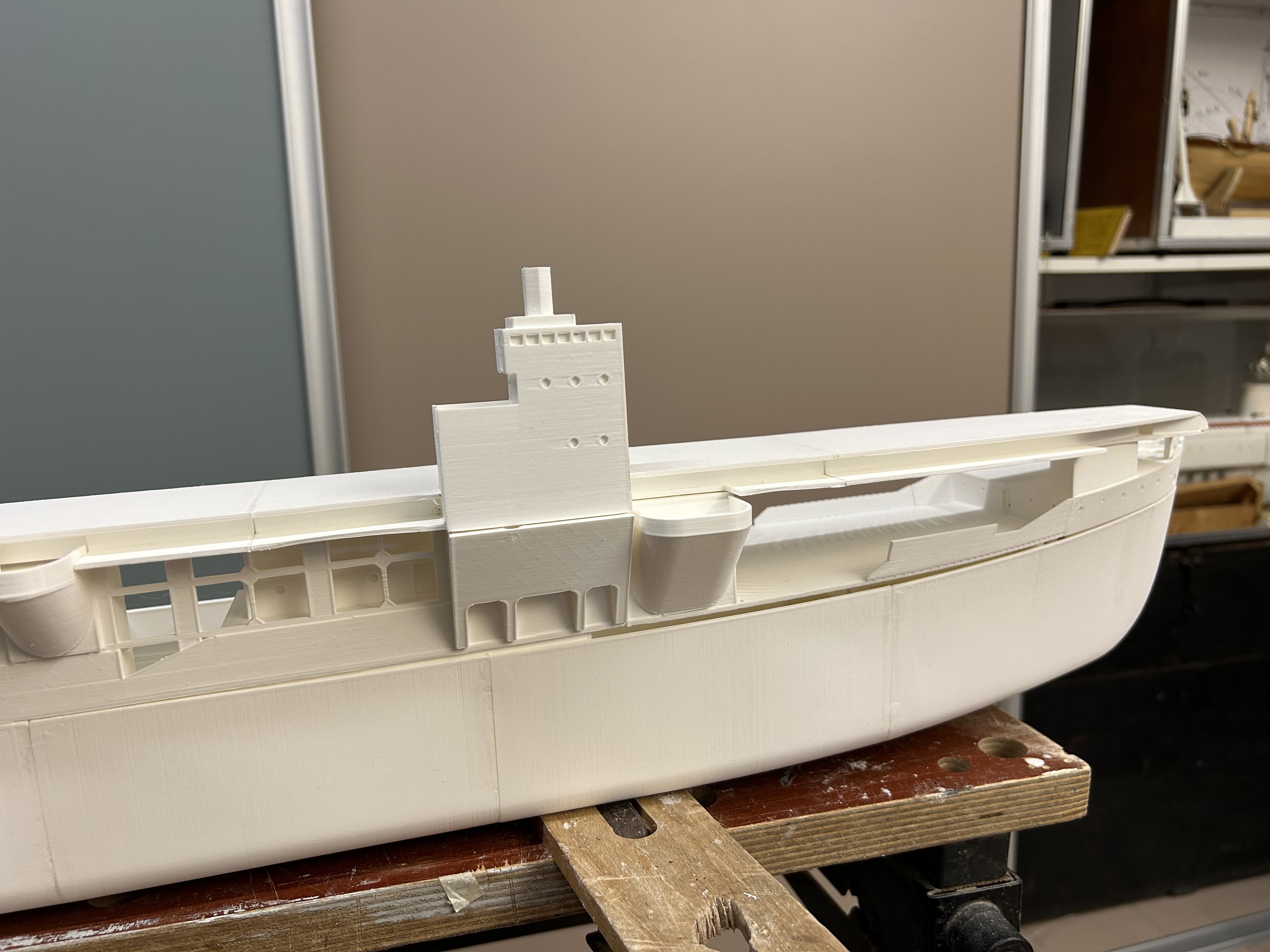
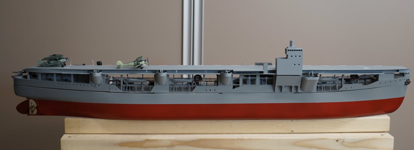
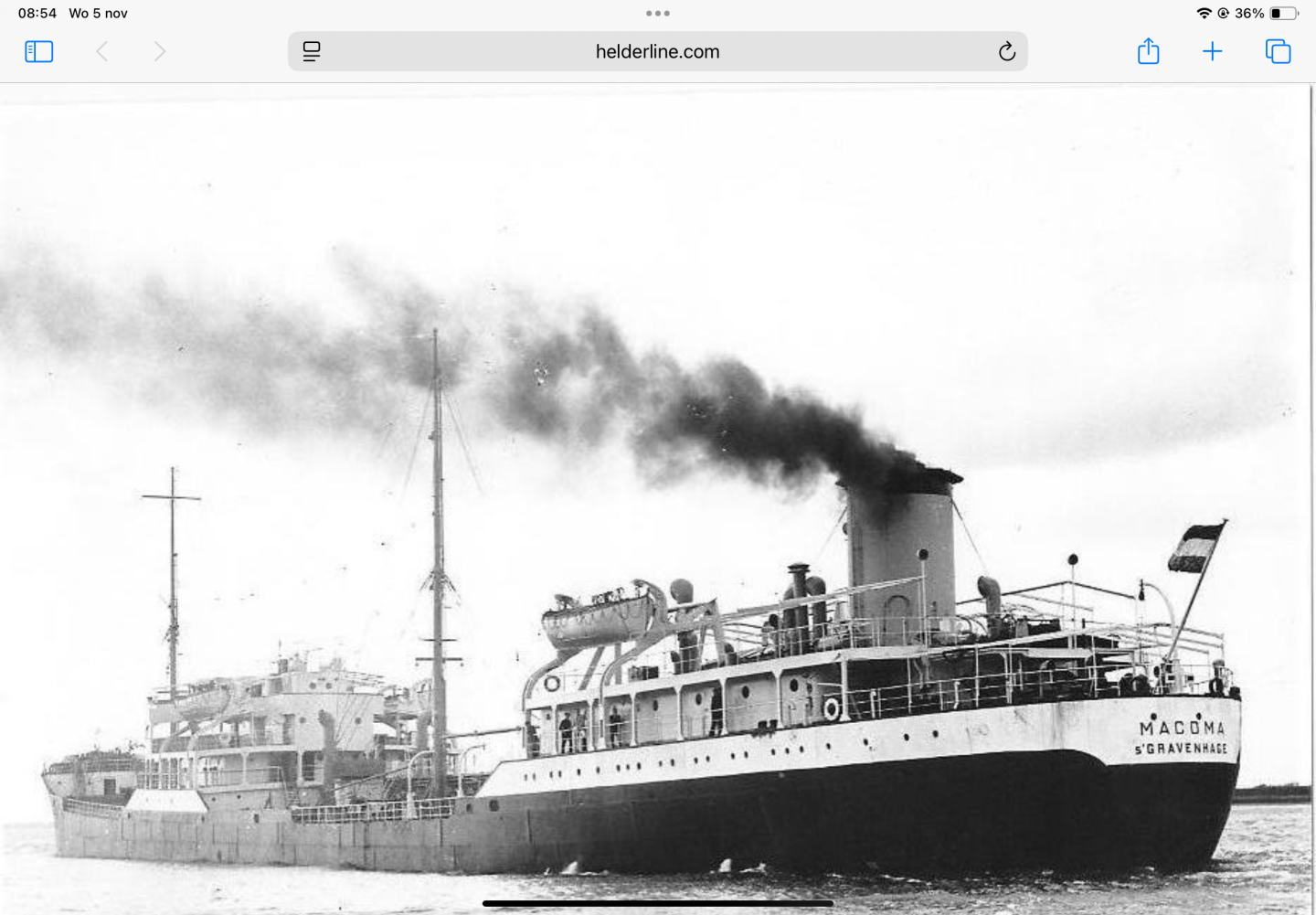
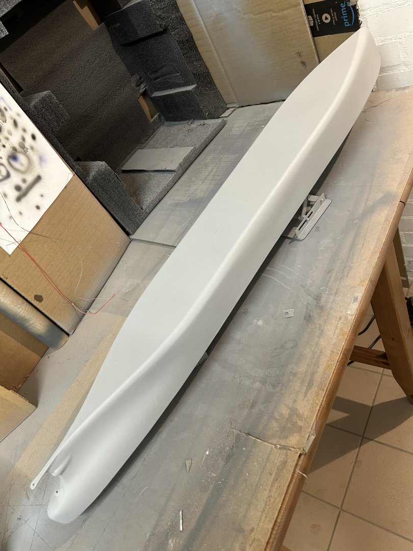
@KeithAug weight wise that will be easy to compensate with ballast. My main worry is the high carrier deck on one side (see below)! after some more sanding, spray filling and priming the hull looked good for painting. The primer had been airbrushed on and is dark grey. I carefully reviewed all the black/white photos of the tanker and carrier and ordered the color matched airbrush paints. Then taped off the underwater ship and airbrushed that red. The next day I retaped the hull and airbrushed the carrier side of the hull in light blue/gray. The dark grey primer on the tanker side is reasonable for a tanker. After removal of the tape the hull looks good! Some touchup will be needed but I added the decks and deckhouses to get a first feel for the effect the “split ship” will have! next step is to apply some clear coat layers as protection, then I can install the drivetrain to test if it has power enough, and find out how much ballast is needed. in parallel is the work on sanding and using filler and primer on the deck parts.


-
Spray putty is a 1-component filler in a 400ml aerosol can. It’s very good for filling smaller scratches and unevenness, quick drying and easy to sand wet and dry. For me, as PLA is so hard to sand, it does a good job of filling the layered patterns the 3D printer leaves behind. I cannot imagine it’s something only known here, I think it comes from car repair but lots of people use it for model boats. Maybe the is a different English word for it? example:https://www.colormatic.com/en/products/aerosols-and-putties/paint-preparation/filling/1k-spray-putty
-
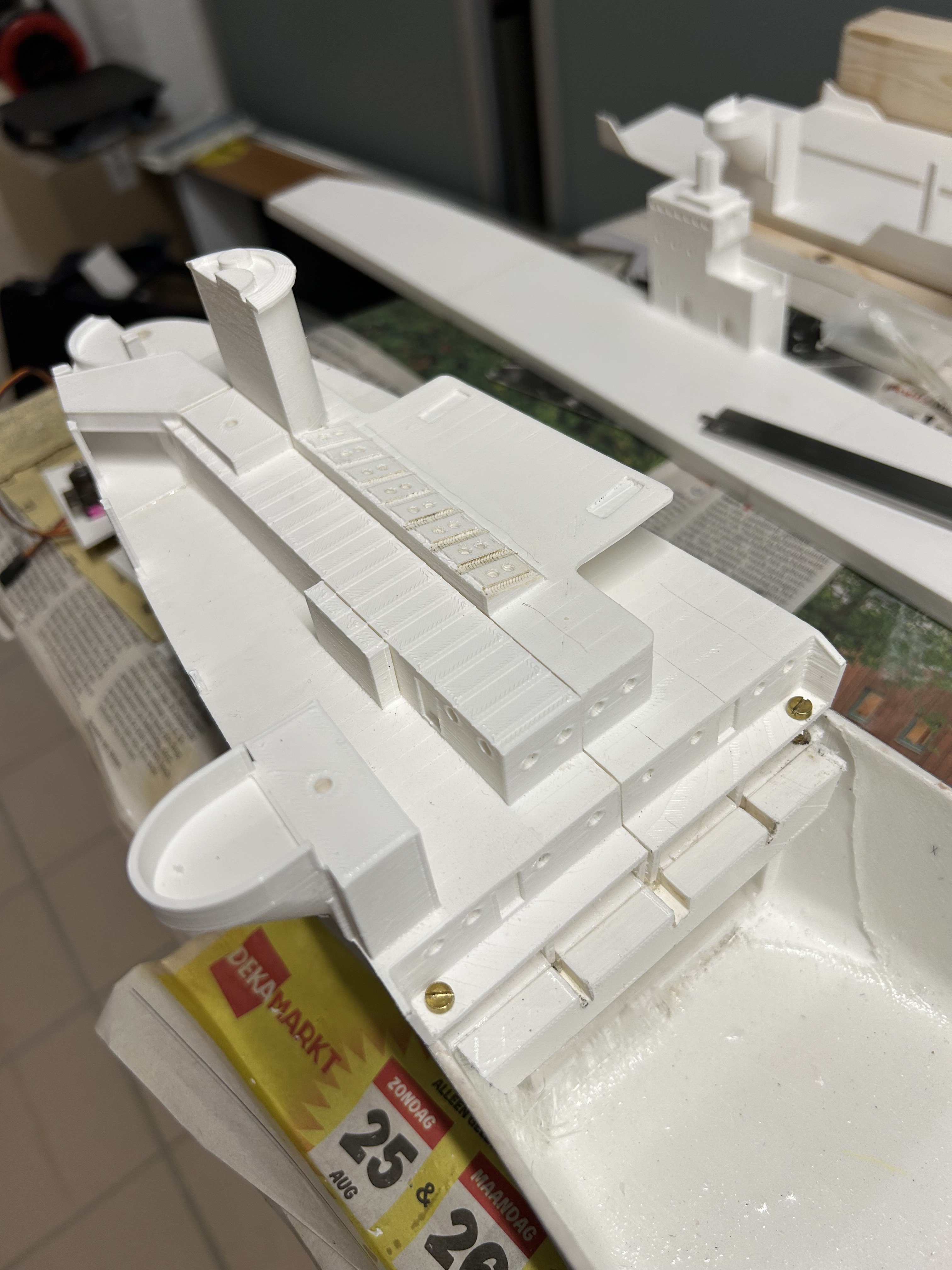
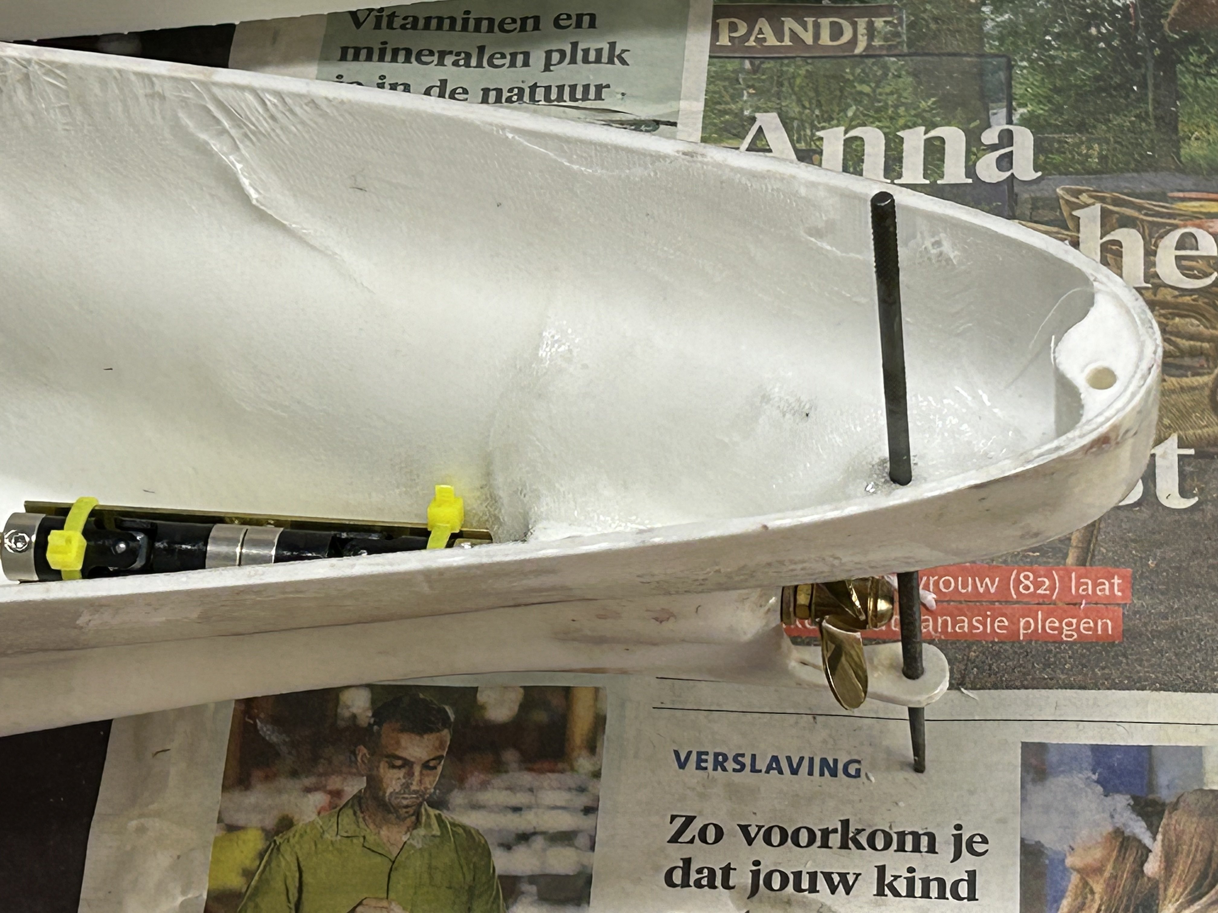
A little bit of progress - the hull has been primed after the spray putty, revealing some further need for sprayfiller. The deck sections have started to go through that process of sanding and filling and… too. i prepared the back part of the deck and aft deckhouse to be removable. Found some m3 insert nuts and using a soldering iron pressed these into drilled holes. I also printed and glued in place a 7mm wide ledge that will get a waterproof seal made of a plate if cell-rubber. That works for my submarines so should keep water out of the tanker too. underneath the aft deckhouse I will need to position all technology that needs to be accessible. Only the ballast will come further forward and after trimming the forward parts of the deck can be glued in the hull. The technology is pretty simple, a servo for the rudder, the motor - shaft assembly, a relais unit that allows switching of the deck lights and a receiver. The motor does not draw a lot of power, so I plan to provide that power with an old set of eneloop NiMH batteries. That will give me 2000mAh at 12V. The aft deckhouse fits well to hull, so I’m happy so far.


-
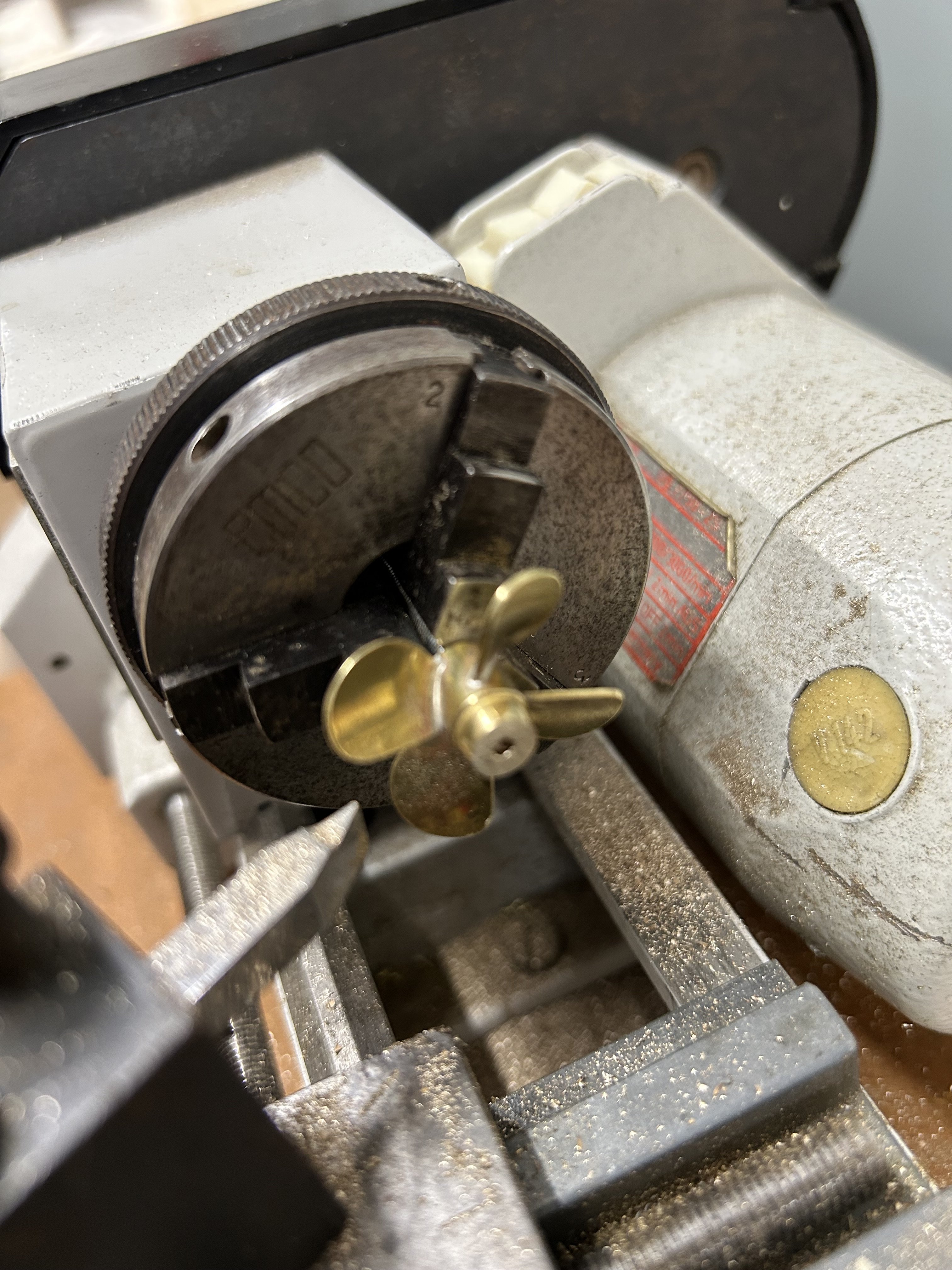
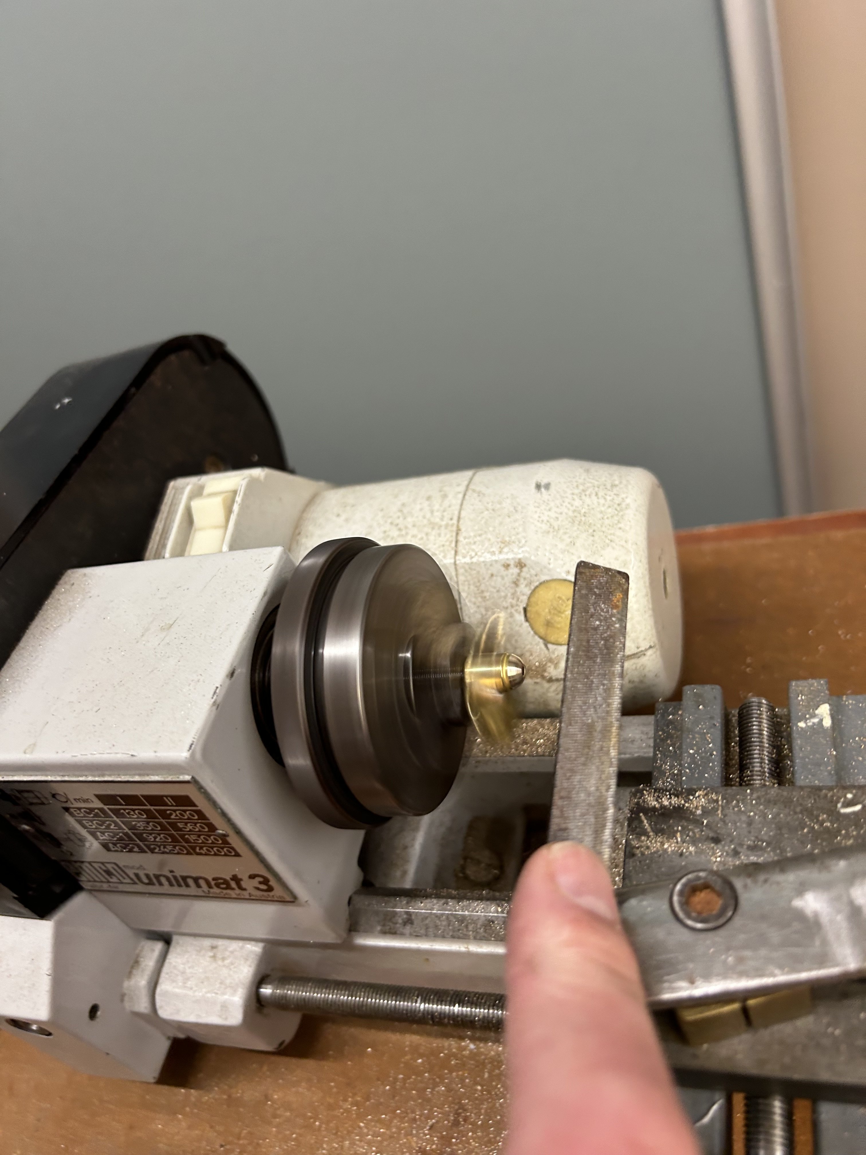
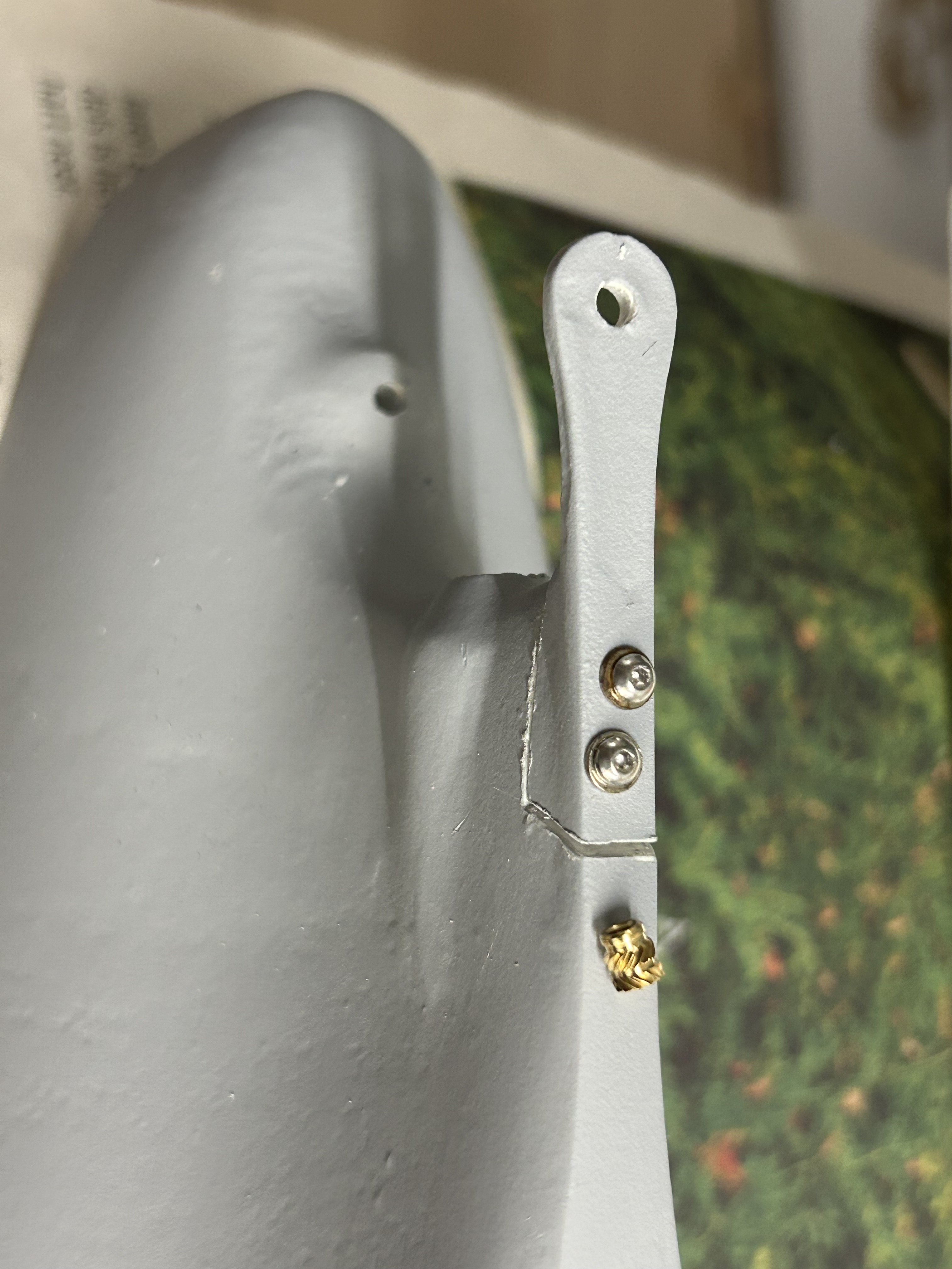
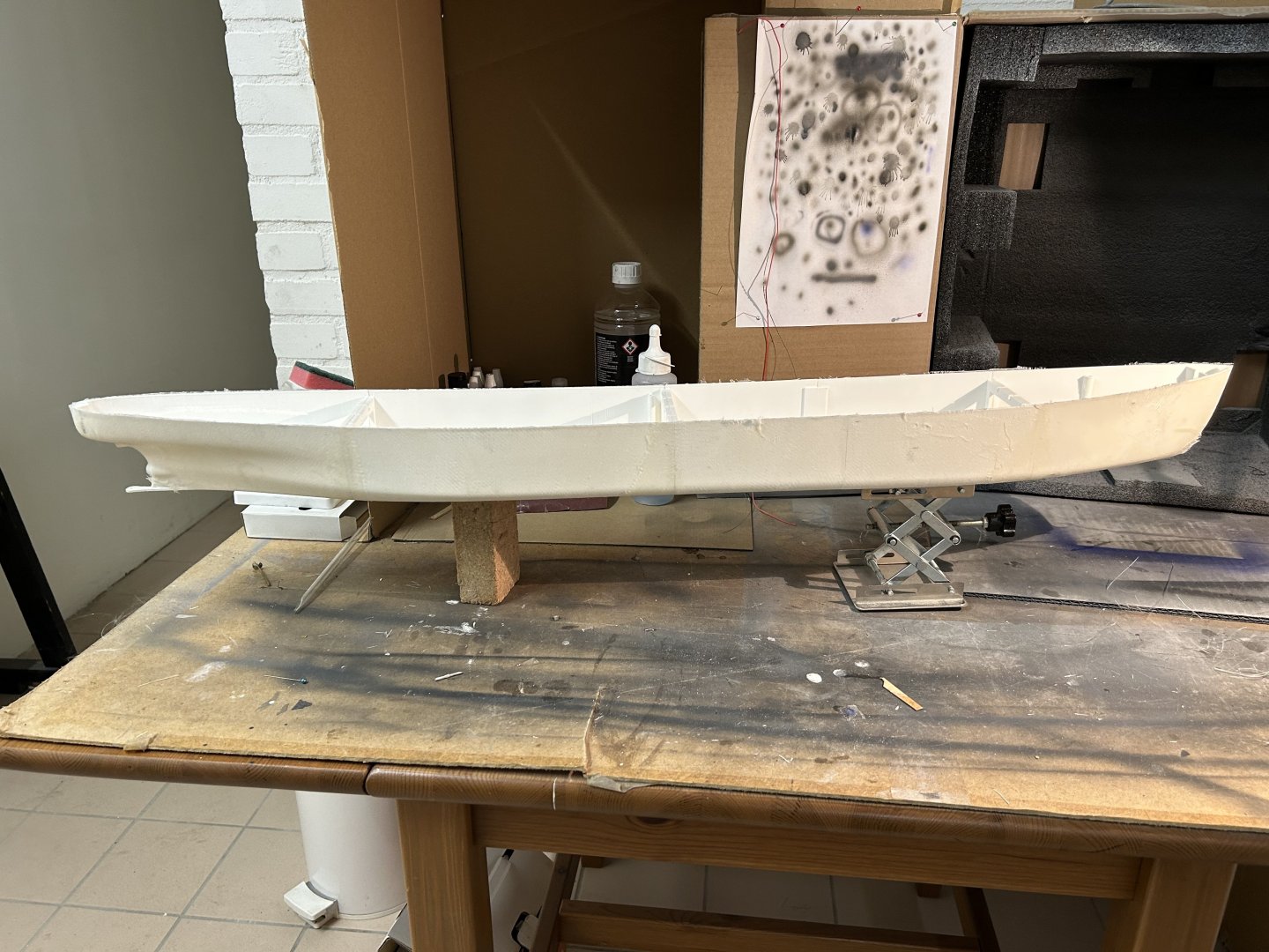
The hull now has epoxy/glass textile both on the outside and inside. After several rounds of sanding and epoxy putty I now used spray putty on the hull. Four layers so far - looks much better (splits between the hull sections are now invisible) but will be continuing sanding…. the superstructures are too complex for spray putty (too many shadows) - so have been sanding them in preparation for 2 comp epoxy putty applied manually. A 4-blade Raboesch brass prop came in, but the hub needs shortening or the rudder won’t fit. Ideal job for my small lathe, first filed off part of the hub, reformed it on the lathe and carefully filled the emerged hole with soft solder. The prop axle and motor mount are made but not glued in yet. to be able to mount a rudder (and maintain it and the drivetrain, I cut off the “foot” of the rudder from the hull (it must have a name…). I drilled 3.2mm holes in the PLA hull, and using a hot soldering iron pressed two 3,5mm M2 inserts into the bottom of the hull. This fixed the inserts beautifully (I did test this on a spare piece of PLA) and allowed me to screw the rudder “foot” back on with 2 M2 bolts. Seems very stable and firm. next back to sanding…


-
That’s what I had when I built Corsaro II, which is a stationary model converted to RC. Like many I added a lead bulb under the keel. It’s screwed into some M4 nuts in the keel and can be removed easily when not sailing. Might be an alternate way for Twilight.
-
That’s brave to test in the sea! The boat looks beautiful but also potentially a bit top heavy and possibly sensitive to wind. Getting as much ballast deep in the boat would be the right strategy!
-
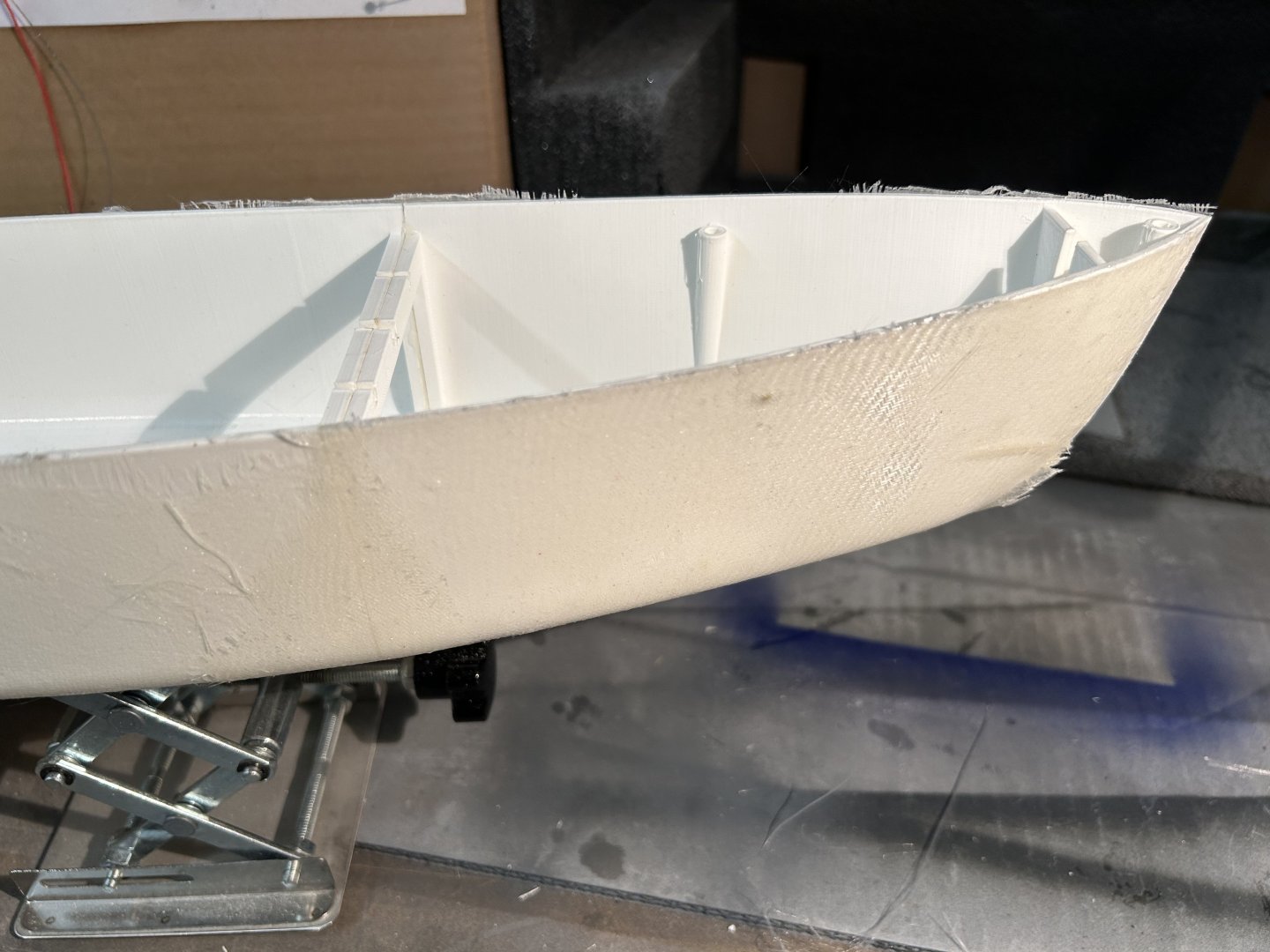
Lots of parts have been printed. It’s now possible to loosely assemble what the ship(s) will look like. then started to treat the hull with a coat of epoxy; and after a few hours curing (still wet) covered with a layer of 80g/m2 of glastextile, then another coat of epoxy in wet. Result is not very good; the glass textile has some folds and bubbles. But the hull is clearly stiffer and stronger. Next I’ll try to sand the first layer and probably apply another layer of glass textile and epoxy.


-
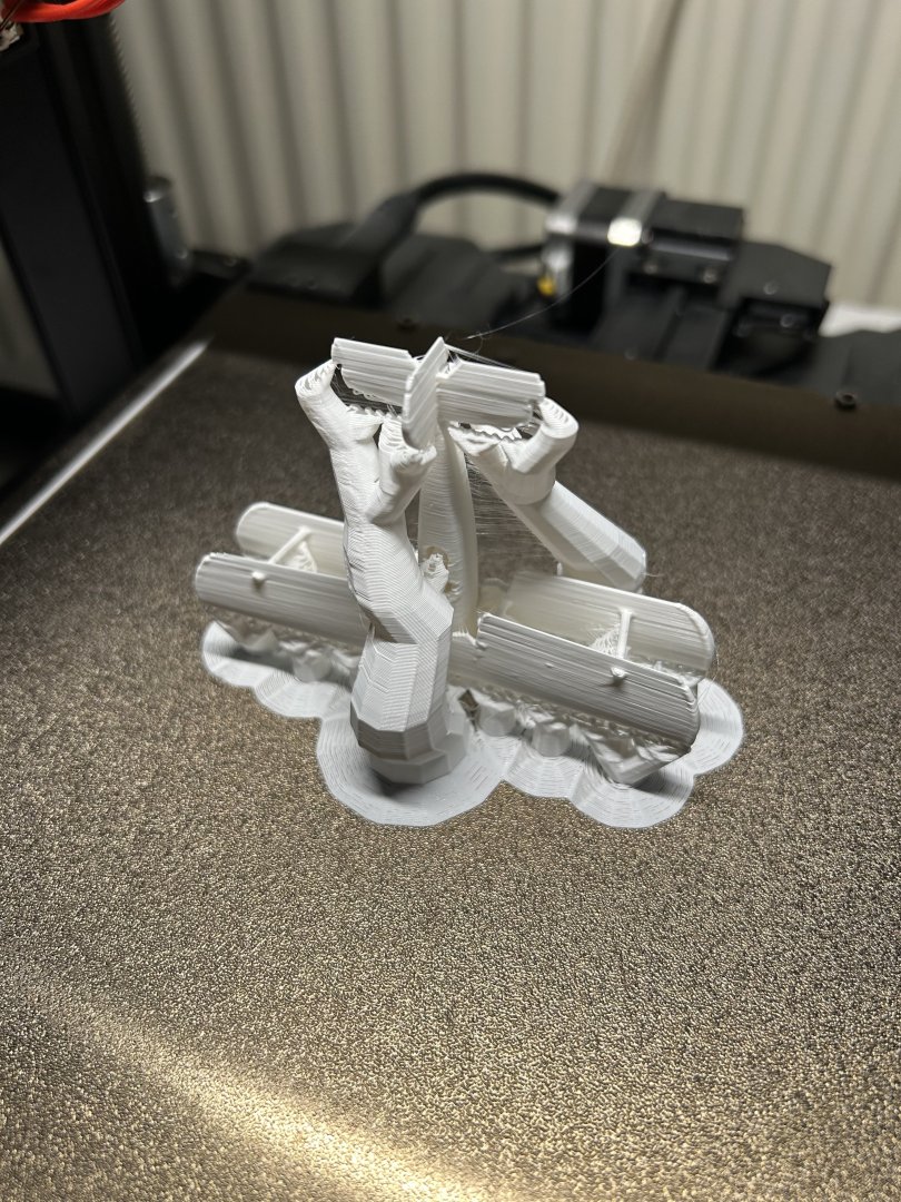
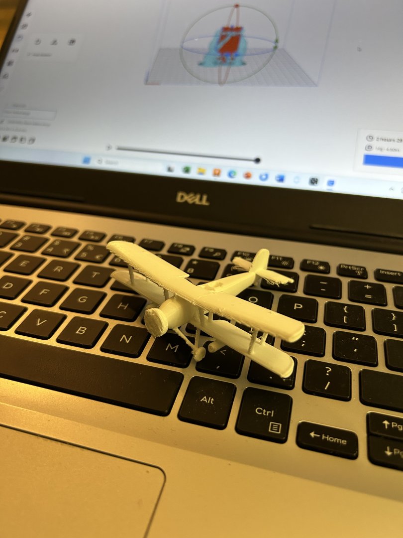
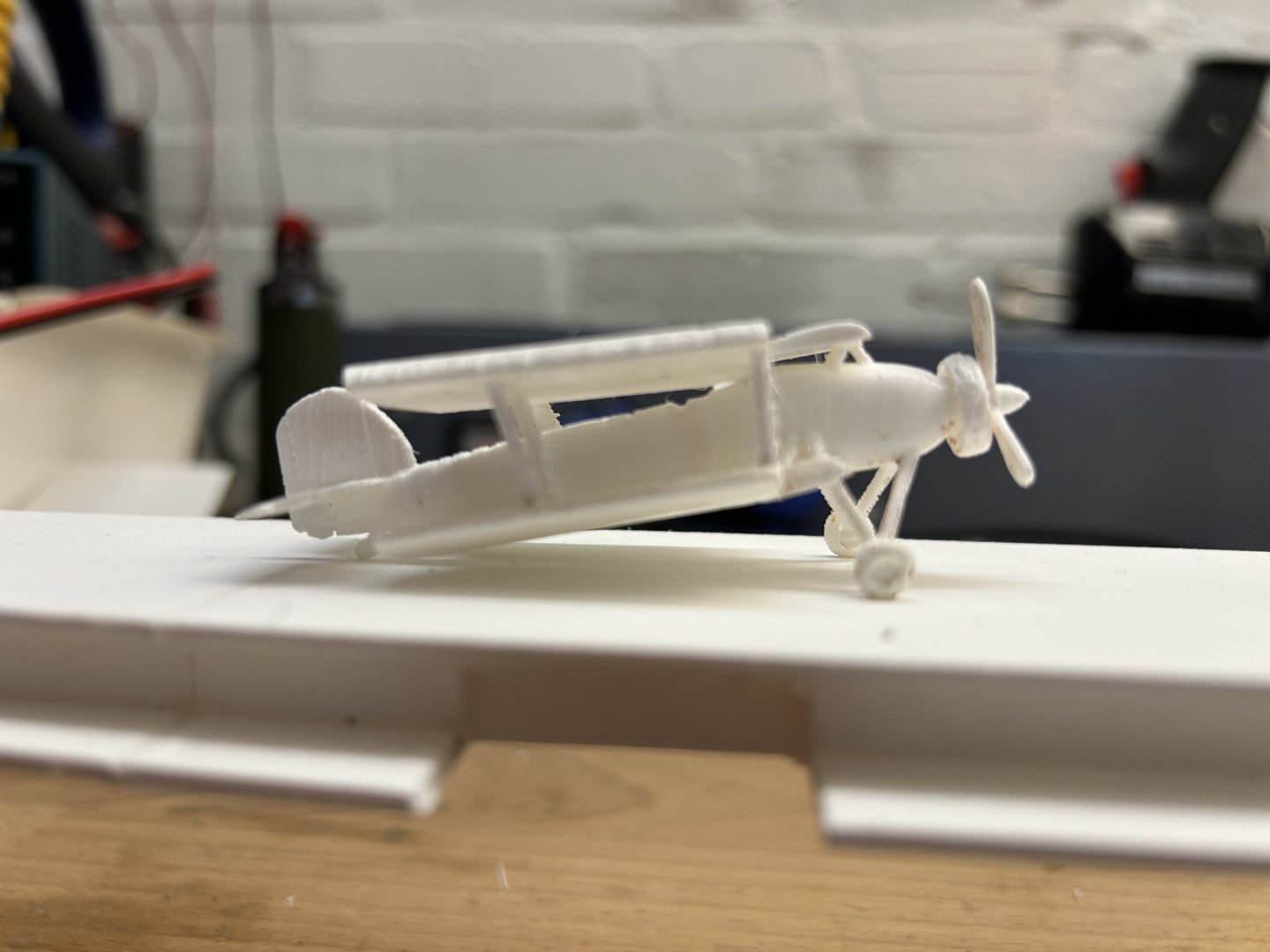
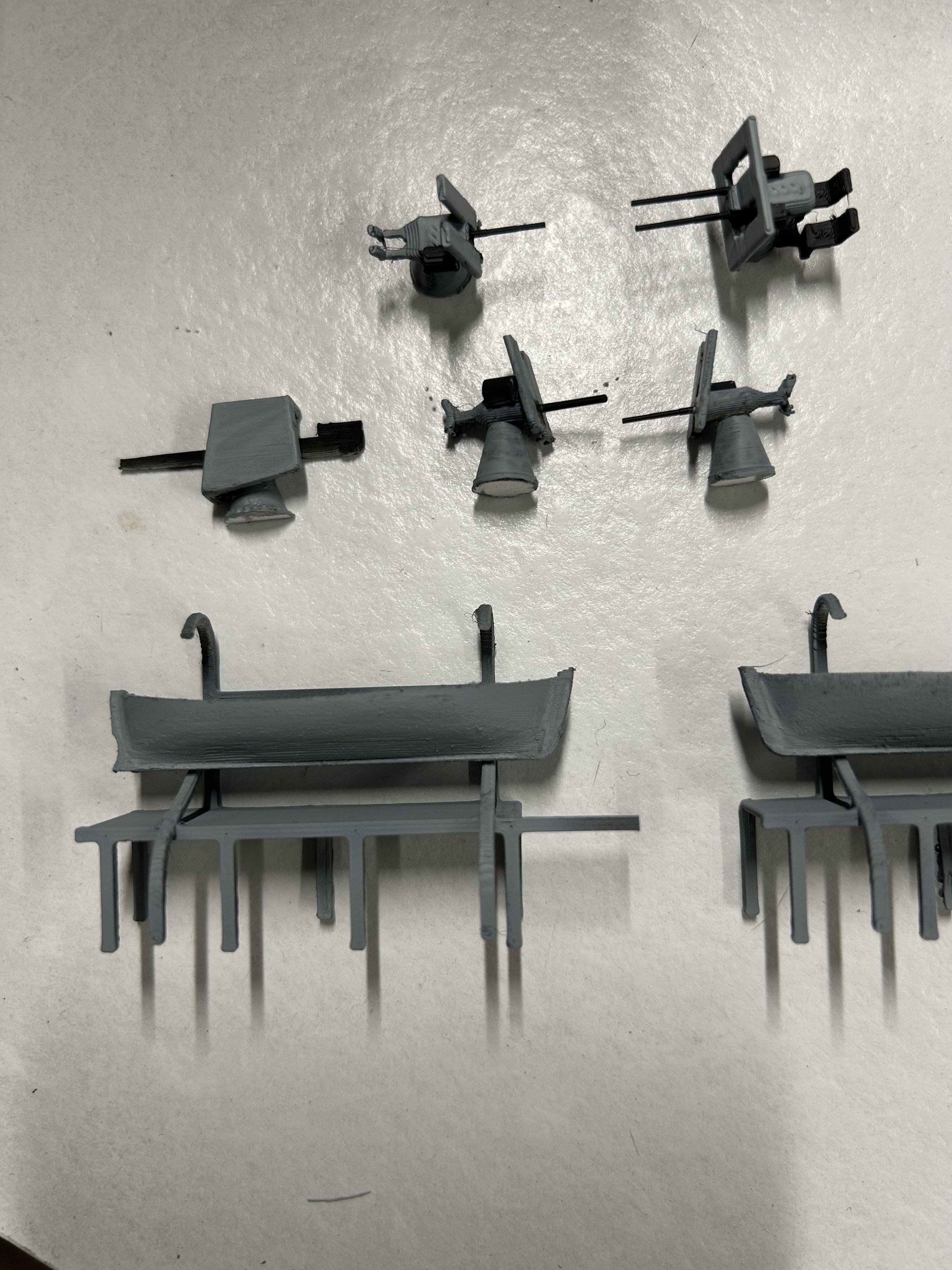
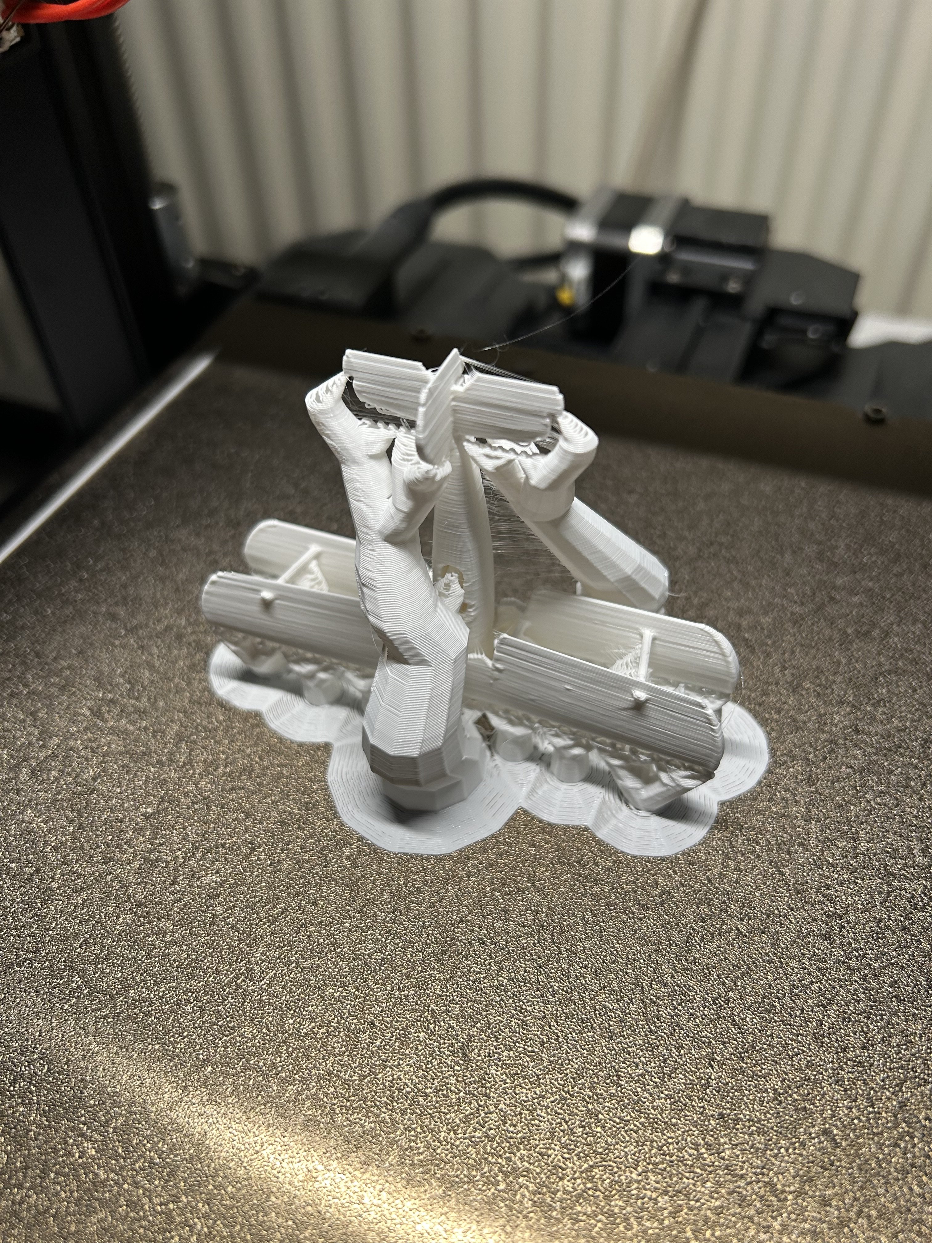
Thanks @NavyShooter didn’t I see a 1/144 swordfish of yours on Thingiverse?😀 Here is how the first prints came out, the first during printing - note the horizontal stabilisers lost contact with the support. Then the full plane after removal of the support, and the second version with folded wings (and temp attached prop) after initial sanding.