


Daryl
-
Posts
71 -
Joined
-
Last visited
Content Type
Profiles
Forums
Gallery
Events
Posts posted by Daryl
-
-
Hi Graham
Thank you. Sorry for being so late in responding. Went overseas to Kuala Lumpur for Xmas and just got back. As for preseason. I just hope the Blues have a better year or I may just have to think about not renewing my membership in 2016.
My next build is a 1:72 scale Viking Knarr. I have already found a problem with the shape of the laser cut keel compared to the drawings in the instruction manual so I am currently talking to Dusek (the manufacturer) to try and sort it out before I start building. I will be putting that all up on the forum within the next week.
Have a good 2015.
Daryl
-
I just found out I could not attach a .doc file so here is an extract of the text of the report that I am sending to OcCre.
.........
Please find on the following pages, a complete and honest report on my build of the “Section Santisima Trinidad” model purchased directly from OcCre on the 29th November, 2013.
Please note that I am not a highly skilled modeler so what may be a problem to me may not be one to someone else and I may be making suggestions that are already common knowledge and have solutions.
This is the first time I have ever thought I needed to write such a report as I have encountered so many problems with this build that I thought I should say something. This report contains not only the problems I found but some suggestions regarding fixing those problems that may help both the manufacturer and someone who attempts to make this model.
I hope this report is of some use to those who read it.
Purchase and DeliveryI purchased the model online directly from OcCre. The purchase process was very easy to use and did not provide any problems.
The delivery of the item was quick and there were no problems. The ability to track the delivery of the model was appreciated.
Model Kit – Parts providedI undertook a complete audit of the kit once it had arrived which identified only one discrepancy. It was:
No. E – 4mm Pulley. Only 36 were delivered instead of the 45 shown on the parts list.
During the build of the model, I found that there were insufficient amounts of one item in particular, that being:
Deck Planking – The widths of the decks is greater than the width of the number of planks identified in the instructions. E.g. the lower deck is 140mm wide and the total width of the planking based on the figures given in the instructions is 129mm. The same goes for all 4 decks. OcCre quickly provided me with additional decking when I brought this to their attention. Not a major issue but one that should not have happened.
Model Kit – Quality of Parts providedMetal. All of the metal parts were of a very high quality.
Frames. I had a major problem with the quality of the timber used for the frames. The ply was very poor and not fit for such a model. Once they were removed from the sheet, they twisted all ways. When trying to straighten they snapped very easily. A modeler should not have to make up a complicated jig to hold the frames in line.
Masts. The timber used for the main mast was warped and could not be straightened. Luckily I have a good supply of doweling so that was easily fixed. Then again, it should not have happened.
Pulleys and Blocks. The 4mm & 5mm clump blocks were of a very high quality. The 4mm & 5mm blocks and pulleys were of a very low quality. The holes in the 4mm pulleys were not in line and I had to redrill every 4mm & 5mm block and pulley. There are very good quality blocks and pulleys available from many sources so it is difficult to understand why OcCre used these.
Cotton thread. The 0.15 cotton thread is of very poor quality. It is very “furry” and catches very easily. It does not look like rope at all. There are very good quality threads available that could be used instead of this.
OVERALL. The quality was below what I would have expected from OcCre and especially for a model of this price.
Documentation
The three documents that were provided for the build of the model provided both confusion and in some cases, inaccurate directions.
I felt that having to move between multiple documents was not the most efficient way in which to work. Each one had a different format, i.e. one had step-by-step instructions, one had color photos and one had plan drawings with differing elevations. They could have all been easily combined into one continuous document.
One example of inaccurate details is the Mainmast Crosstree. The one shown in the color photo differs to the one shown in the plan drawings in that it had an additional cross piece.
InstructionsAs previously mentioned, the instructions are spread over three very different documents. Experienced modelers may not have a problem with these instructions, but those who are still learning such as myself, need as much assistance as possible so as not to make too many mistakes.
This might just be an “age” things, but I really enjoy the following format for instructions:
Step #. What to do - Where to do it - How to do it - Image/Photo/drawing of step & result.
The order of a build should be such that everything is done when it should be done. (Each part has a number and they are entered in the Parts List in the order they are meant to be done, so I have included the numbers to show how far apart some of these are) Examples of this not happening in the instructions are:
- The Waist (111, 112), Battery (113, 114, 115) and Deck (116, 117, 118) stairs. They are only installed after the hull and decking has been completed. It would have been much easier to install them on their deck (16, 25, 42) when building that deck.
- The Mast pin rail (108). This should not be installed until the very end of the build as it just gets in the way of trying to tie off all the rigging.
- The Loft (105, 106, 107). This should be installed in conjunction with the lower deck (16).
- The sails (206, 207, 209, and 211) are laced to the yards before any of the running rigging. If you do this, when you attempt to tie the Clew Garnets (216, 217, 218, 219) and Buntlines (220, 221, 222) to the yards, you will be tying them over the lacing (205) used to attach the sails to the yards. Instead, the Clew Garnets and Buntlines should have been tied off on the yards prior to the sails being laced.
A photo and a part number is NOT an instruction. An example of this is the building of the Masts, Rigging and Running Gear. There are no step by step instructions for these as there is for the Hull. Instead, you have photos (some with a lot of items in the photo), part numbers and descriptions and plans. Considering the instructions for the Hull took 2 and a half pages, not having any written instructions for the rest seems surprising to say the least.
OVERALL. The documentation could be a lot more user friendly. I personally think it could do with a total review and possible re-write.
Scale drawings- The plan documents give both front and side elevations for the masts. They are very detailed but have to be studied carefully. Some of them are confusing. An example is on page 5.
-
The top drawing shows a side view of the completed Main Yard.
- In this view, there are two blocks partially hidden by each Main Yard Spars. These turn out to be the blocks used for the main clew garnets.
- If this drawing was “rolled counter clockwise” so as to give the top view as shown in the bottom drawing, these blocks should appear on the “top”. Instead they are shown hanging from the “bottom”.
- The error is in the top drawing. They should be shown in front of the Main Yard Spars.
- Following these plans exactly as shown could result in having the blocks located on the wrong side when you go to use them later on.
- The same problem happens on page 6 for the Topsail yard.
- The plan documents for the rigging are of a very small scale. I must admit that I got totally lost when trying to tie off all the running rigging. The instructions tell you to install 8 Belaying Pins in the side pin racks yet there are 9 tie-offs for each side. As for the mast pin racks, they hold 5 pins but there are 8 tie-offs on one side and 6 on the other.
OVERALL. The Scale drawings in some instances are too small and too complicated. They need to be enlarged to give a better view of the work that is to be done.
Overall- Anyone wishing to build this particular model should spend a considerable amount of time to read and re-read all the documentation so as to obtain a very clear understanding of what needs to be done and in what order,
- Following the instructions/plans/photos blindly will more than likely lead to problems,
- All instructions and plans should be provided electronically (CD, link to website for downloadable file etc. which would allow modelers to print out just the section they need in any size that suits them.
- Check all parts for not only their quality but their usability and lastly
- Do not let it get you down. I am reasonably pleased with the end result of my build but that does not get rid of the frustration I had in building it due to the issues I have raised both in this document and in the Model ship world forum. My unbiased wife Kaye tells me it is beautiful so how can I argue with that.
Go for it. I will take on board any feedback you may want to provide. I can handle criticism so long as it is followed by a suggestion as to what may have been a better/more suitable way to have done what it was that has caused the comment.
Other than that. I look forward to putting my next build (Viking Knarr) on the Forum when I start it in the New Year and following the great builds that are underway.
-
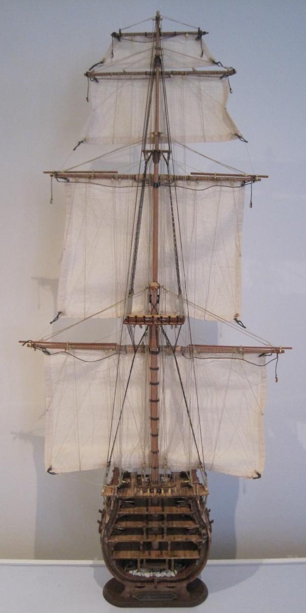
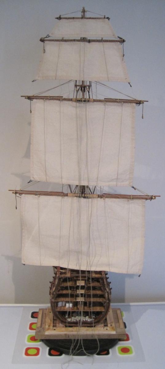
Well, she is finished. Spent the last two days tying everything off. Not happy with the end result though, especially the running rigging. I just could not fit everything in. I have so much to learn. If anyone knows of a book that is viewed as being the "bible" of how to rig a model, please let me know. In the mean time, I will keep looking at all the great models on this forum hoping to learn more from them.
Here are the last two photos. If you look closely, you will see the shortcuts I have made. I was thinking of doing another "section" model but I will try and learn a lot more before I start one.
I will now finish my report and that will be attached in the next day or two.
-
I am pleased to say that there actually IS light at the end of the tunnel.
I have made a huge effort to finish this project as it has been around for a long time now. As a result, I only have 1 days work to go and it will be completed.
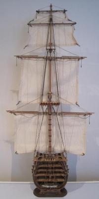
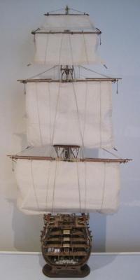
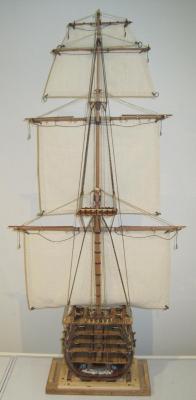
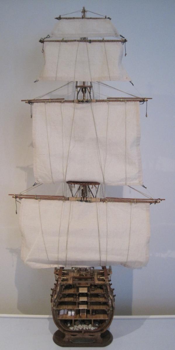
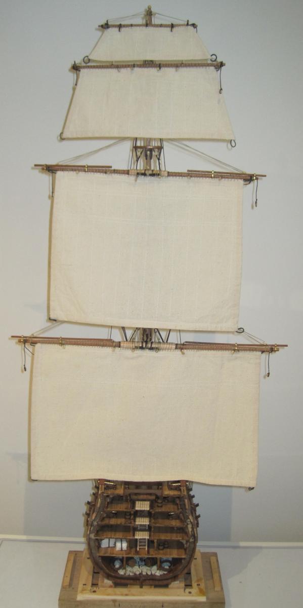
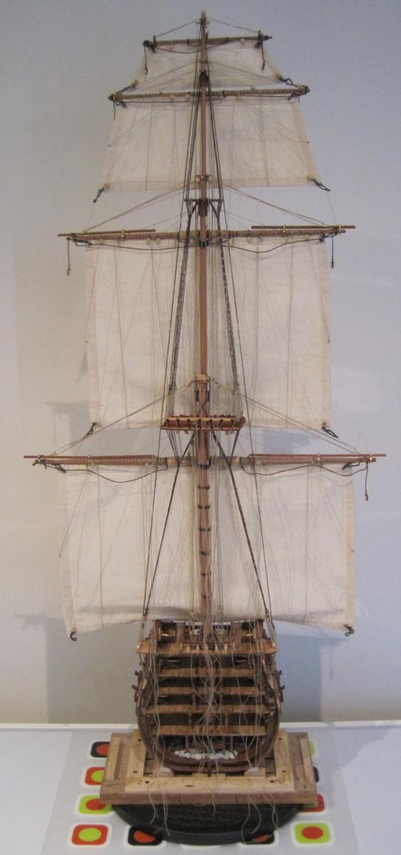
I have spent the month completing the sails and rigging except for the final tie off of the rigging. Needless to say, as can be seen in the last two photos below, I have heaps of cord hanging free just waiting for me to get it all tangled and knotted.
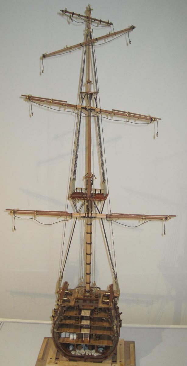
The first photo shows the yards suspened by the halyards.
The next shows the lifts attached.
The next two photos show two views of the hanging of the sails. I must say that I love the sails. They are really well made and were a joy to work with.

And then I started on the rigging and ran into a few problems.
The first is the mainmast rail. This should NOT be installed until the very end of the build. It just gets in the way of tying off everything.
The second are the side and mast pin racks. They are not long enough to have the pins spaced sufficiently to cater for good tying off. They are too cramped. I could be wrong but I think the pins are not scaled down correctly.
The next photo shows the buntlines hanging yet to be tied off.
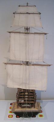
And the last shows the Sheets, Garnets and Leech lines attached but not tied off

Should be finished soon.
-
Well, I had an inkling that the rigging was not going to be simple.
In photo 74 of the coloured instructions, it tells you to attach 6 x 4mm pulleys, labelled "E". Very clear photo of the two holes in them, so that is what I did.
In sheet B of the large black and white rigging diagrams, it indicates that the rigging is to be connected to 5 x 4mm blocks labelled "D".
I will not be changing the pulleys to blocks as there was not enough of them provided in the first place.
I have found the rigging diagrams to be very confusing and not helpful. Maybe I am just not experienced enough yet.
I have also changed brands of the cord I am using for the rigging. The provided cotton is too fluffy. I have also had to drill out a lot of the pulleys and blocks as the holes are woeful. The joys of being retired and having nothing to do but build model ships. NOT.
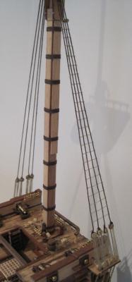
Having said all that, following is a photo of the Main yard which is now swinging nicely from the Main mast.
-
Hi folks
I was surprised as to just how much Huon pine is up for sale in Tasmania. There are timber yards that only sell Huon pine. It is still expensive though but well worth it. I am making a small box out of huon pine to hold my micrometers. I am hoping my dovetailing does not ruin the look of the timber.
Daryl
-
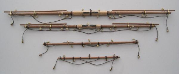
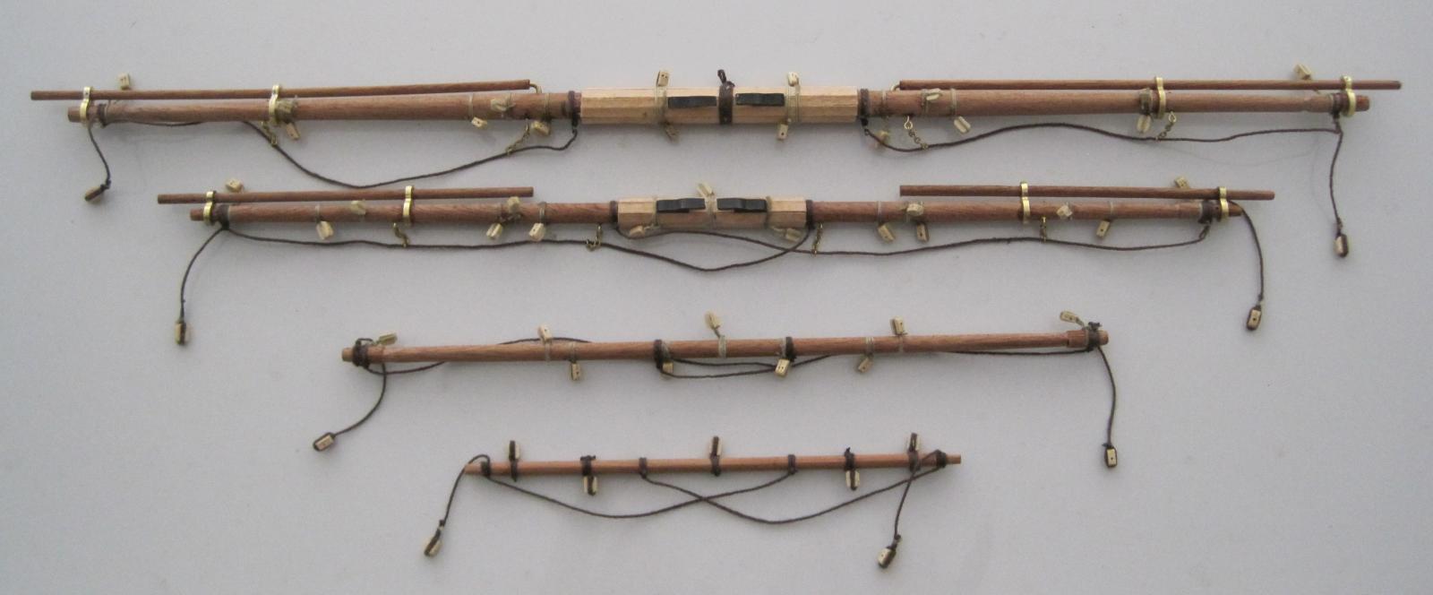
I have now completed the yards and not without some problems. Maybe I just need new glasses but I feel I found a problem with the diagrams they gave.
There are 2 images for each yard. One is shown from the front (or back) and the other from the top.
Using the Topsail yard as an example. When you look at the image showing the front of the yard, you can see to the R/H side of the Topsail yard support board that there is a 5mm block and then a 4mm block attached. In between them there is another 4mm block which is located behind the Topsail yard spar. So far, so good. Now, if you look at the top view image (which is only the front view image rotated 45 degrees, it shows the 4mm block infront of the Topsail yard spar. It should be behind it.
I found this occurred many times so it will be interesting to see what happens when I start with the halyards etc. I am hoping it does not cause too much of a problem as the thought of cutting them off and retying does not do my little grey cells any good.
And here is a photo of the completed yards. I think I have a lot to learn about these.
-
Hello Brian
Yes, everything straight out of the box. The rope is not the best at all. Very fluffy and catches on everything. I am now very interested in learning how to make rope. I willbe building a small model Viking Knarr next year, so I think I will use that as my test bed for rope making.
Daryl
-
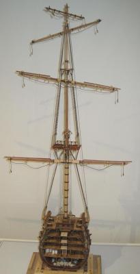
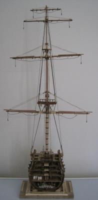
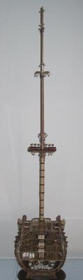
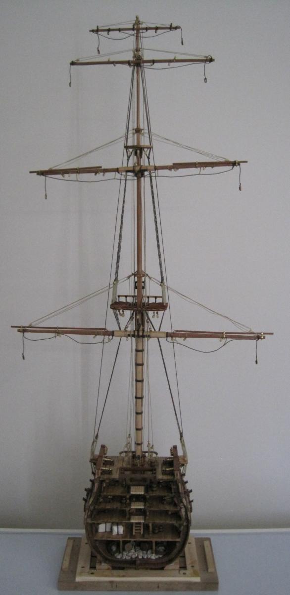
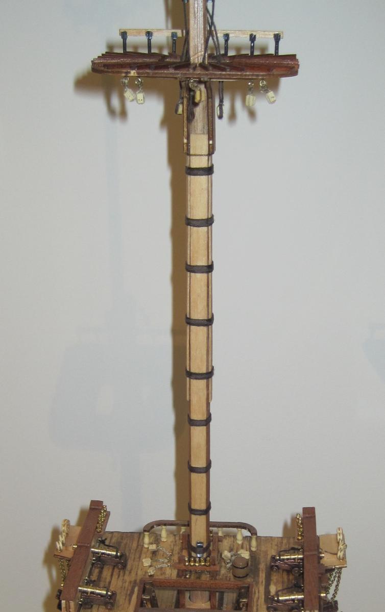
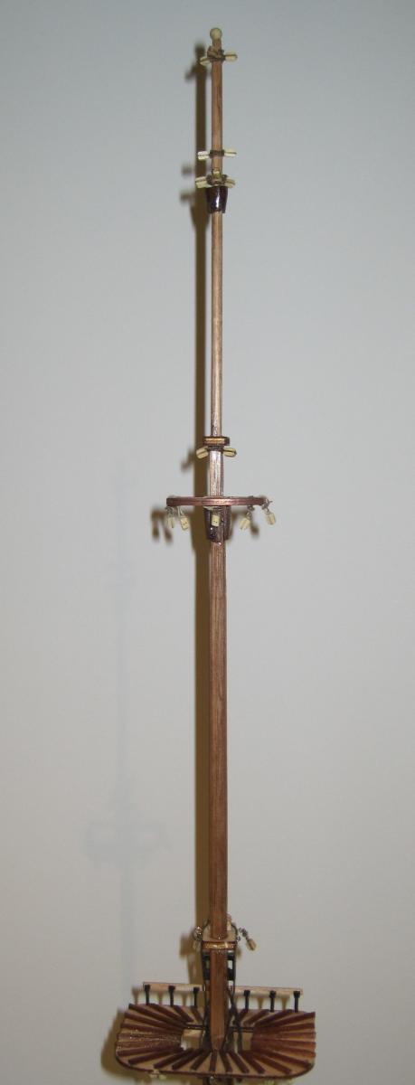
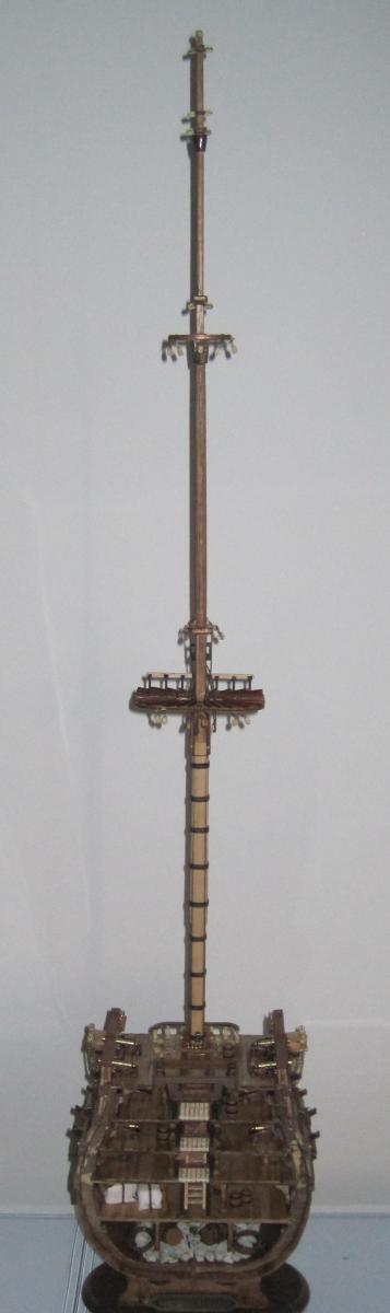
And the rigging grows and grows.
Photo 73 - Ratlines completed on Main Topmast shrouds
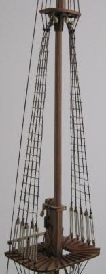
Photo 74 - Main Topgallant shrouds installed
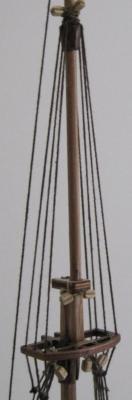
Photo 75 - Mainmast backstays installed
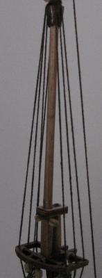
Photo 76 - Mainmast rigging completed
So now we move on to the Yards and Spars and all their bits and pieces. I am sure that will keep me occupied for lots of time.
Stay tuned.
Daryl
-
Hi folks
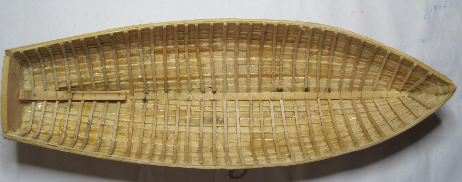
It has been a long time since my last entry and a lot has happened since then. I have decided not to build the small lathe I previously mentioned, and the result of that is that I will not be building the steam engine for the Queen. I have therefore finished building the boat to a level that we are happy with and I have attached photos showing its progress. I guess that I am really a "kit" man and having seen some of the great ships in this forum that have been built from kits, I think I will stay doing that and over time, improve my skills in areas such as rope making, rigging and decking. Thank you to everyone who has been in touch.
Daryl
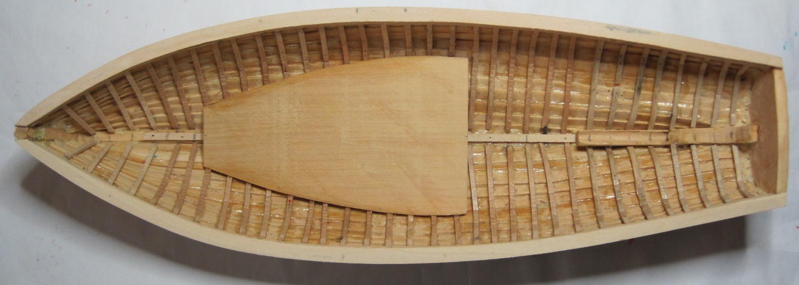
All Timbers (Ribs) fitted

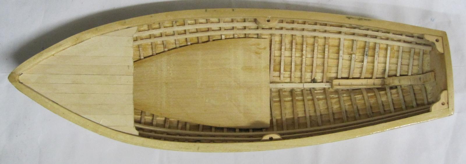
Installation of Gunwale & Boiler deck
Gunwale & Boiler deck fitted

Stringers fitted
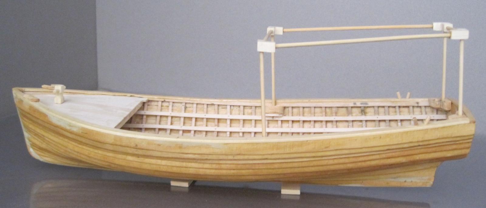
Foredeck & awning supports fitted

Double-bit bollards fitted in stern
Staghorn bollard & Fairleads fitted in the bow
Awning frame installed

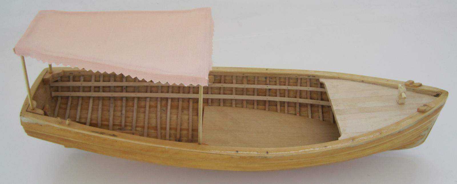
Awning installed

And thre she is in all her glory. My apologies to those who were looking forward to vision of her puffing around the water feature. You never know, it may get resurrected some time in the future. I have not installed the aft decing just in case.

- GrandpaPhil and GuntherMT
-
 2
2
-
Back again. Just had to get away from this rotten weather for a while. I have now completed the ratlines on the Main shrouds and started the ratlines on the Main Topmans shrouds.
Cristi. Thank you for sending the images but I was not been able to open them so i went directly to your build and saw them there.
Photo 71
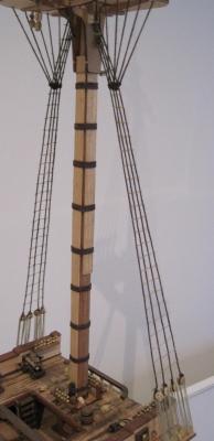
Photo 72
-
Took some time off and went on holidays. The weather it too bad to be staying in Melbourne just now.
I have now attached the Main and Topmast shrouds and started tying the Ratlines. Just love all those clove hitches.
Photo 68

Photo 69
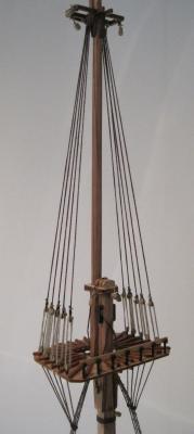
Photo 70
I get sore arms from holding them up tying the ratlines, so if anyone has a simple way for tying ratlines, please let me know. e.g. The shrouds are pre-asembled (cut to length and blocks attached at ends), then laid out flat on the work table, pinned to shape on top of a piece of paper which has the location of th ratlines drawn on it, and then the ratlines tied. Once the are all tied, the shrouds are inserted through the crosstree/cheek and then attached to the block on the chain plates using the lanyards. Sounds easy, but I am sure there could be a catch somewhere.
-
Hi
I am at the point where I would like to stat making my own ropes. I have been searching for suitable plans of a "machine" but to date I have not found one that I like. A lot of those on the internet seem to be for general purpose large rope and not what would be used on a model ship.
I prefer to make my own tools rather than buy something off the shelf, so I am hoping someone can help me out by pointing me to where I can get some plans, either free download or purchase.
regards
Daryl
-
Hi Bindy. Thank you for the comments and I will pass on your birthday greetings to Geno. I will keep everyone informed of my progress and publish the report for all to see. I have read the logs on both your build and wish you all the best.
The only advice I will give you is 1) to read all the instructions several times before you do anything. Sometimes the tell you to do something later on when it would have been a lot better to do it a bit earlier and 2) Be patient and take your time. Rushing can lead to having to try and undo a mistake that can be difficult to do. As you will see from my log, I have multiple varying projects underway which gives me a break from each so I can look at them and think about them before getting back to them.
I am sure you will thoroughly enjoy the journey
regards
Daryl
-
I took some time off from building the Trinidad to build a Cigar Box uke for my nephew's birthday. Now that is finished it is time to get going again.
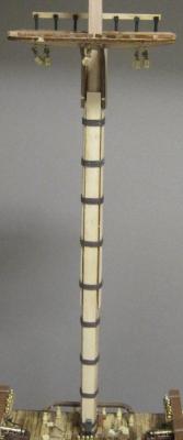
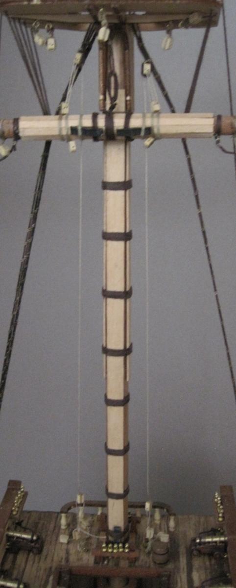
This entry covers the completion of the masts. Once again I found discrepancies in the assembly instructions.
eg. On Page 3 of the mast plans, it shows only 1 x 4mm pulley above the Top Gallant mast cleat whereas on Page 4 it shows 2 x 4mm pulley's and 2 x 4mm blocks.
In the coloured photo instruction document, on it shows a completely different mainmast crosstree to what has been provided and is shown on page 3 of the main mast plans.
I am not sure if people are interested in reading about the problems I have found but I will keep adding them in case someone is thinking of buying this model and they can use my comments as a heads up. My final report on the build to OcCre is going to be very interesting. I just might add it here for everyone to see. Any comments?
Photo 65
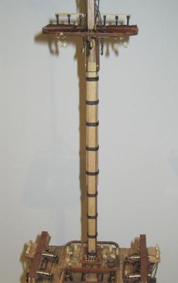
Photo 66
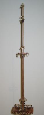
Photo 67
I am taking another break now to build my wife a Japanese Shamisen Kankara.
Happy building all.
-
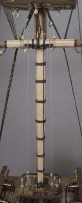
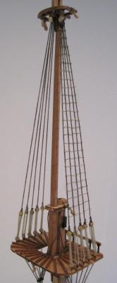
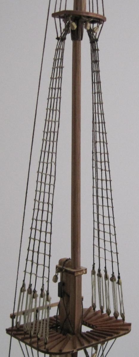
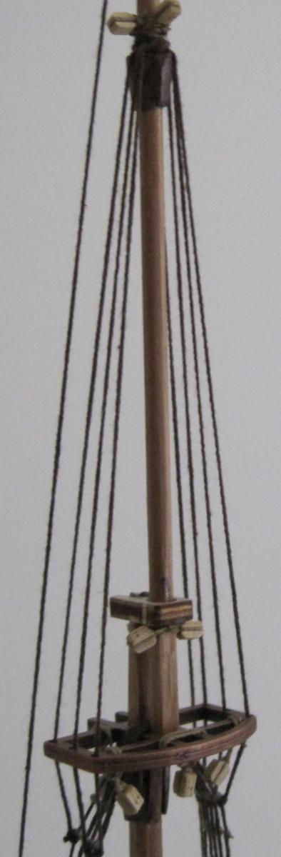
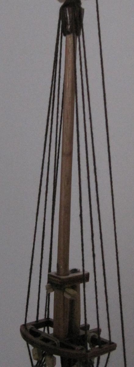
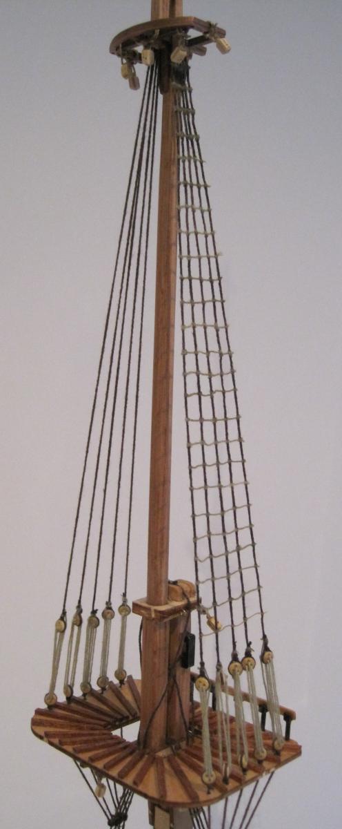
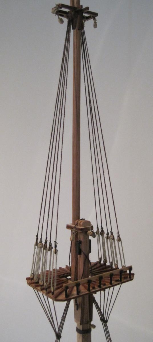
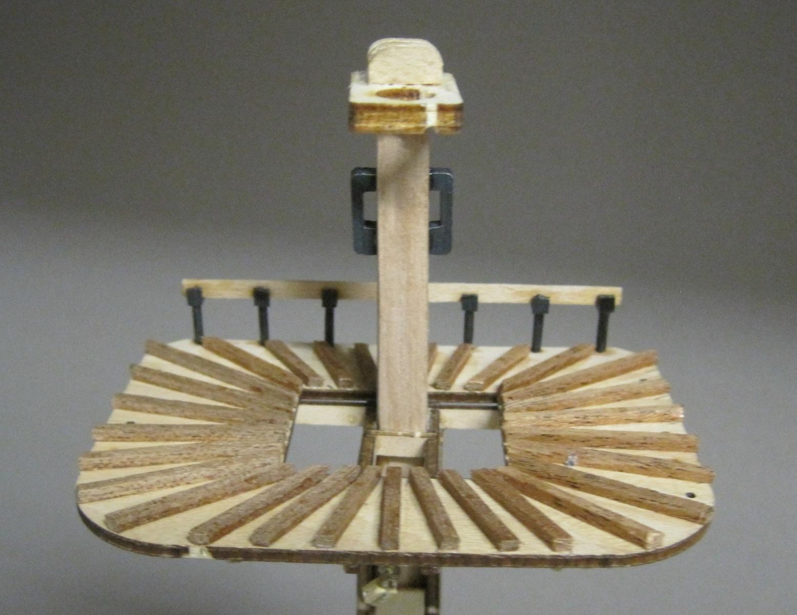
So now it is the Masts and Rigging's turn. My 12mm sapelli Lower mainmast was too warped to use so I found a great piece of 12mm hardwood dowel at our Men's shed which I will be using for all 3 mast components. I turned the Lower mainmast down on the lathe which certainly made it a lot easier for me. I built the top trestletree completely before fitting to the mast. I remembered blindly following the plans in a previous build when I had to try and fit the blocks/pulleys underneath after the mast was fully mounted. Not a good move.
Photo 63

144 - Top trestletree
145 - Top crosstree
146 - Spreader
147 - Main top
148 - Mast top splint
149 - Large cap
150 - Platform cap
151 - Top column
152 - Top guard rod153 - Fairleads
D - 4mm block
E - 4mm pully
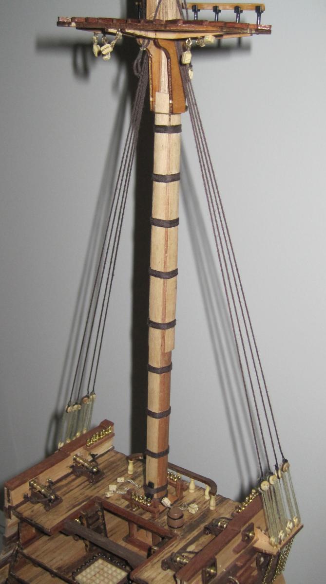
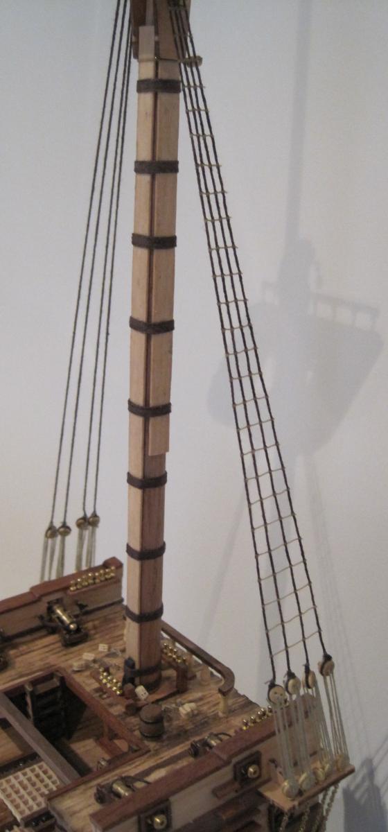
Photo 64
139 - Lower mainmast
140 - Batten
141 - Fish
142 - Woolding
143 - Cheek
155 - Cleat
-
Hello Daryl.
Nice progress since I last looked in.
Must be putting in a few hours to get this far so quick.
Regards Antony.
Hi Antony
That's what happens when you are retired. Lots of hours to fill and what better way to do it.
Daryl
-
On the home straight to finish the hull component.
This entry covers the remaining steps.
Photo 52
Steps 113 - 125
113, 114 & 115 - 1st Battery stairs
116, 117 & 118 - Lower deck stairs
119, 120 & 121 - Bales
122, 123, 124 & 125 - Barrels and Stones were installed at a later stage and shown in a following photo
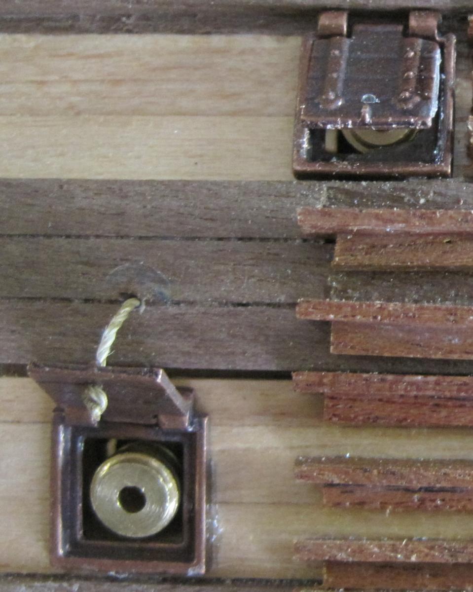
Photo 53
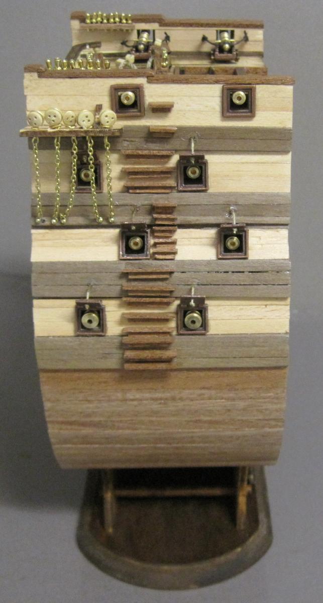
The photo in the instructions show the gun port covers in an open position but do not show anything holding them open. I am presuming that they want them glued open.
Photo 54
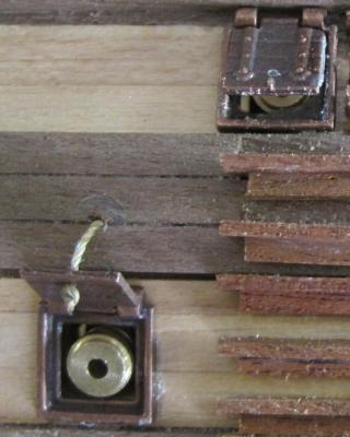
Instead, I drilled each port and added a small rope which is attached through a hole in the hull.
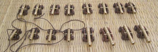
Photo 55
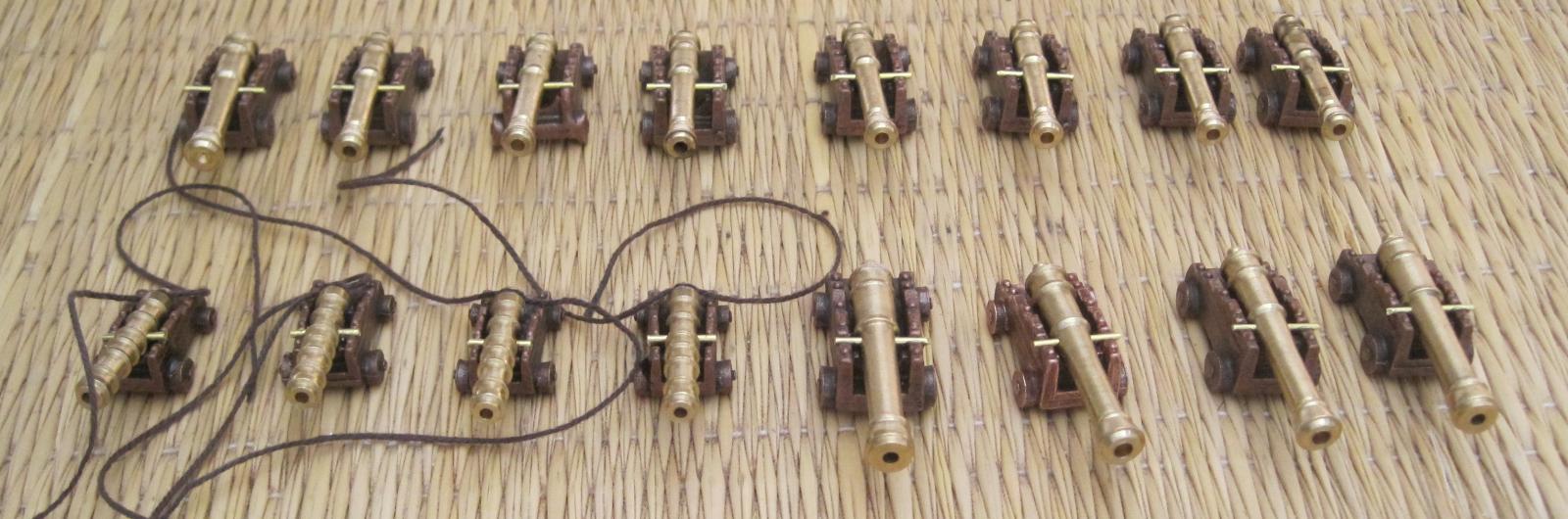
Steps 126 - 133
126, 127 & 128 - Large guns
126, 128 & 129 - 2nd and 3rd guns,
130, 131, 132 & 133 - Small guns
Photo 56
Steps 122 - 125
122 , 123 & 125 - Barrels
124 - Stones
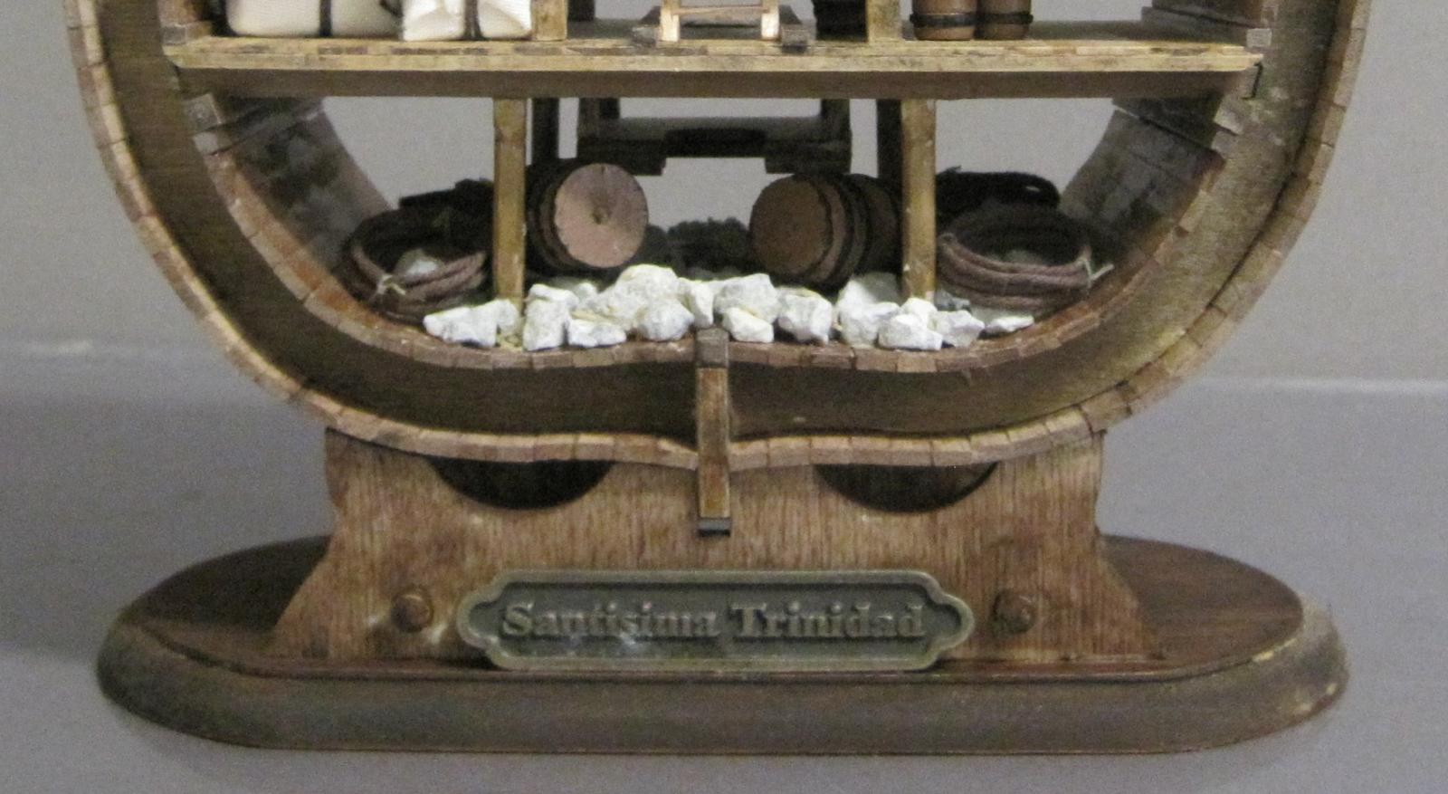
Photo 57
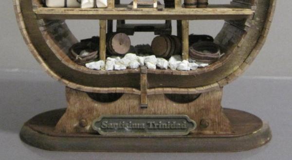
Steps 134 - 138
134, 135 & 136 - Base
137 - Nameplate
138 - Ropes
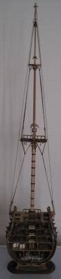
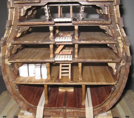
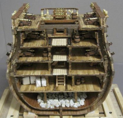
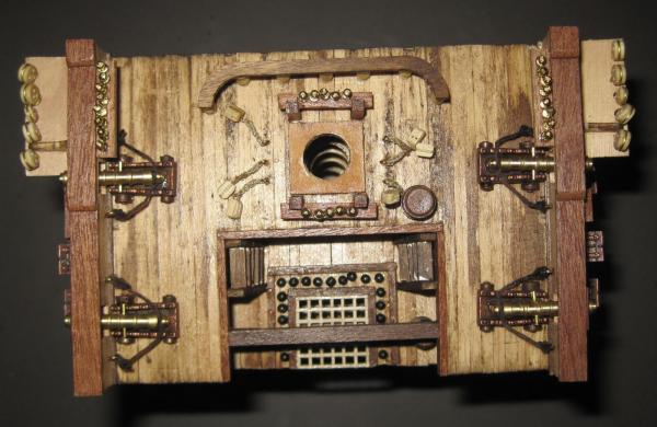
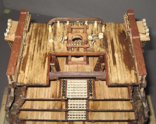
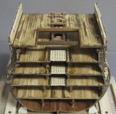
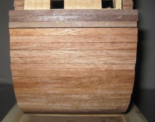
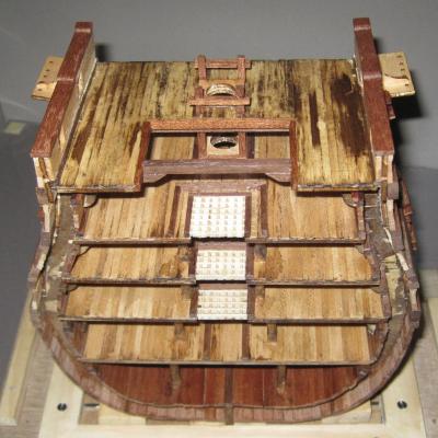
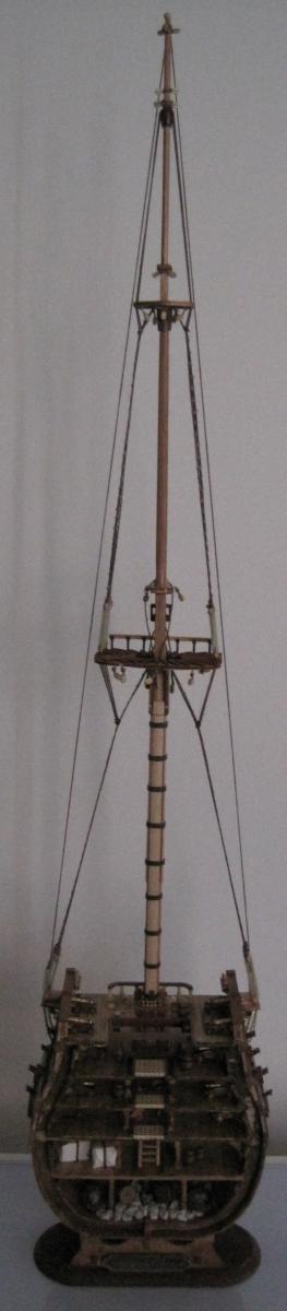
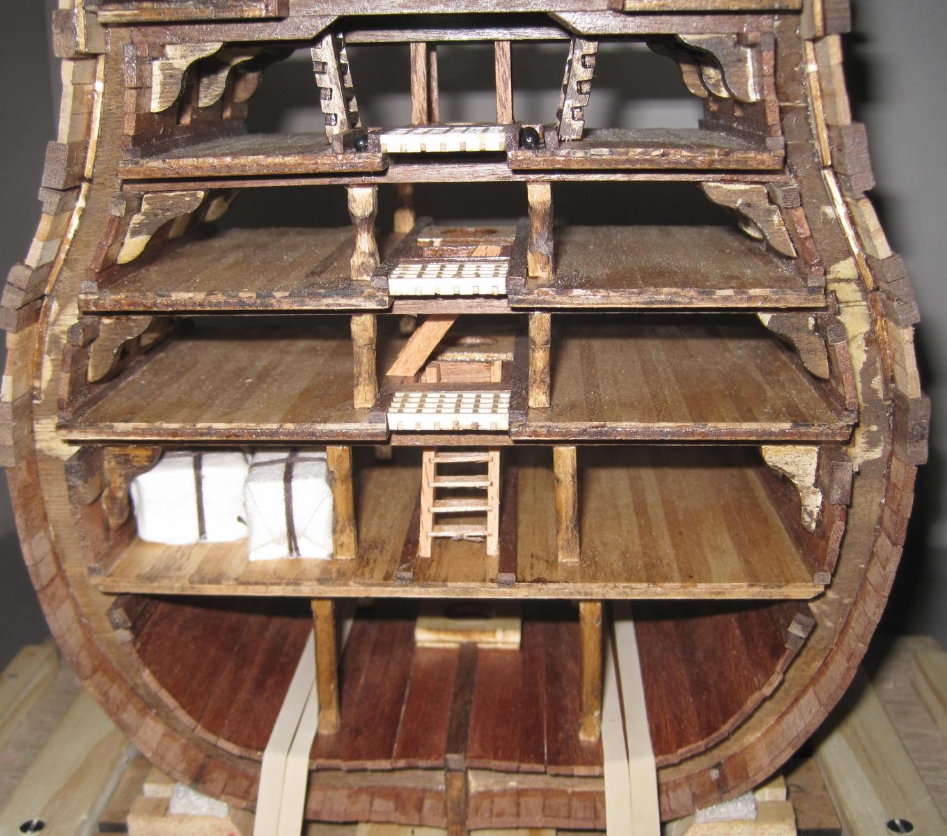
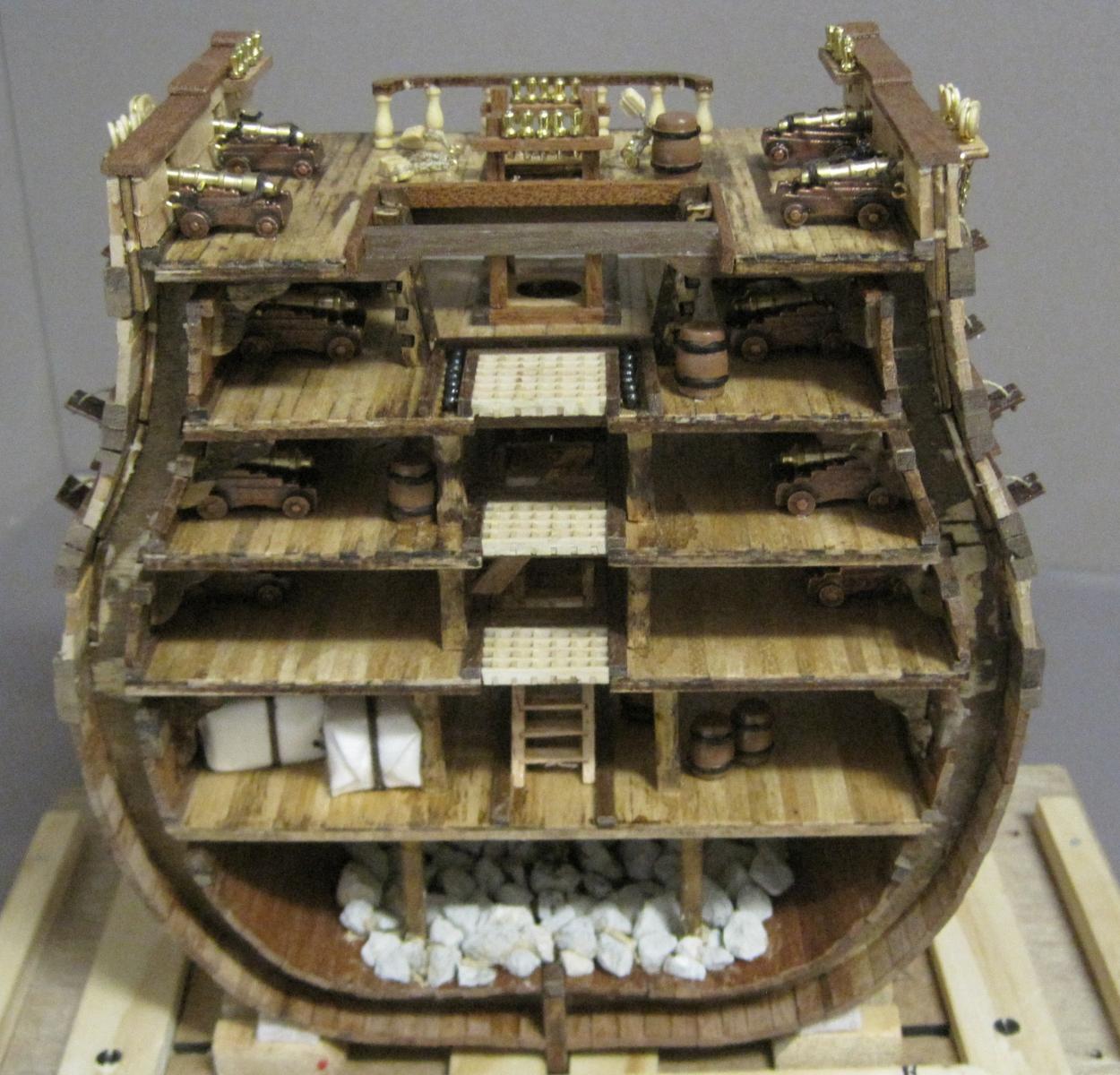
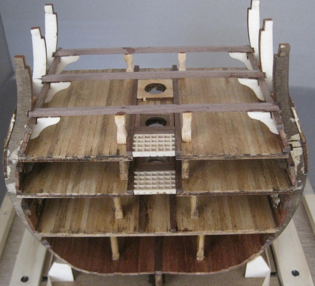
And now we come to the completed Hull.
Photos 58 to 62
Aft view
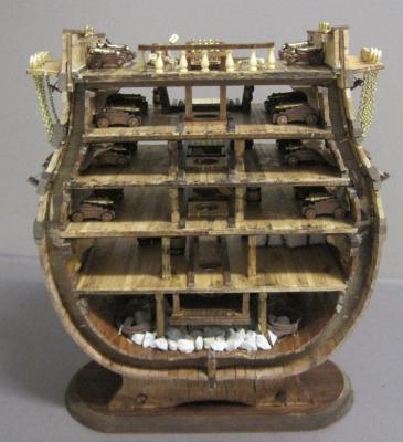
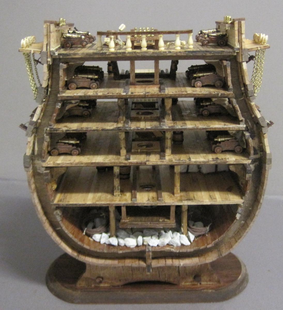
Forward view
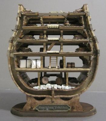
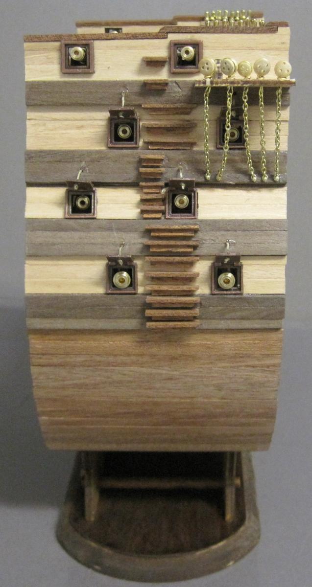
Port view

Starboard view
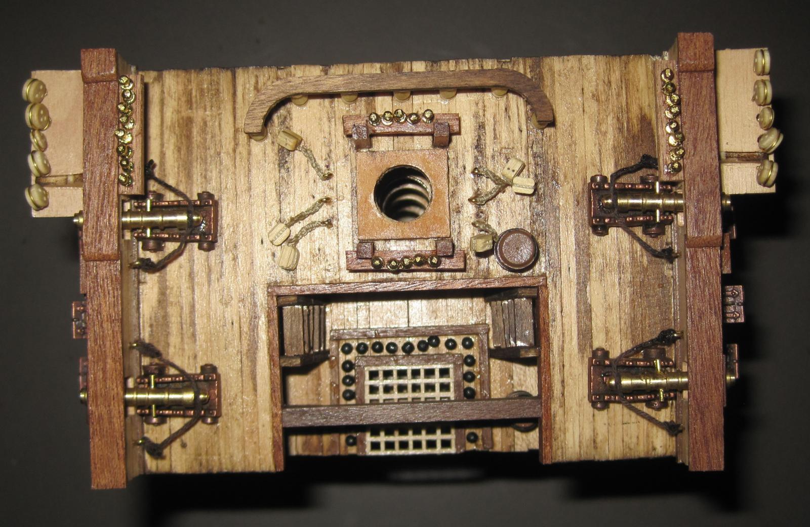
Top view
As you will be aware from previous comments, the build so far has been an interesting one. I have learnt a lot of lessons and appreciated your feedback.
I think I will do some serious reading and checking on the internet before I start the masts and rigging.
I hope you have enjoyed the build so far.
Daryl
-
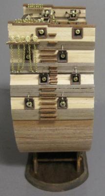
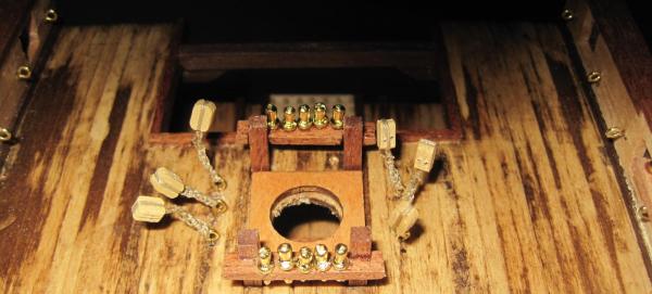
Back again. I am now getting into all the "fancy bits". I think it is looking good and I am still enjoying the build.
This entry covers steps 99 to 112.
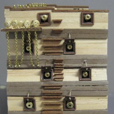
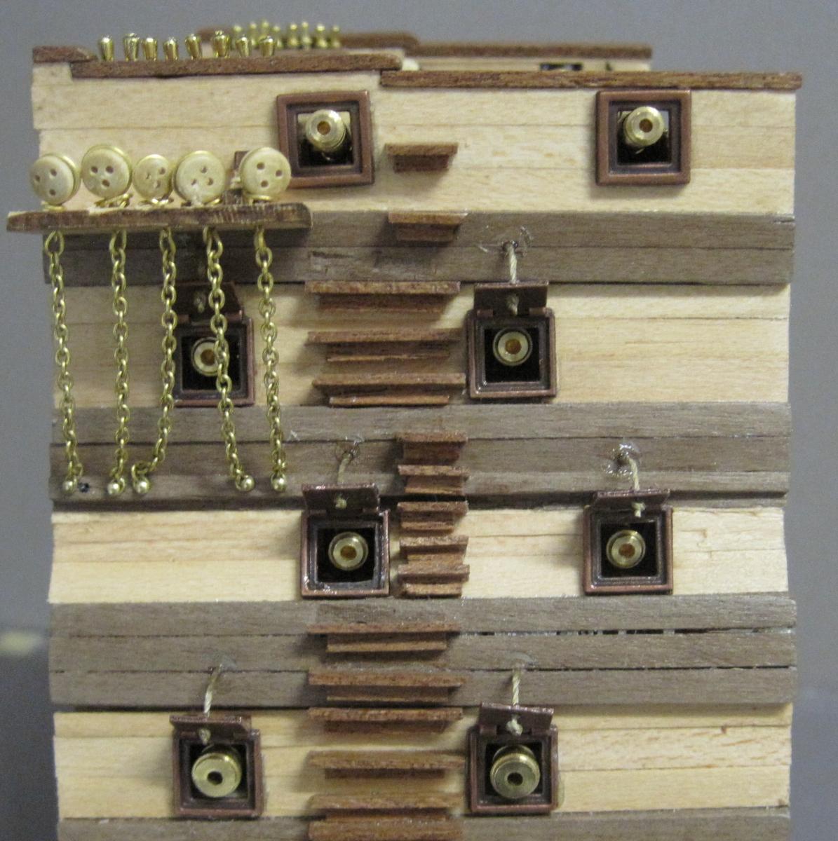
Photo 47
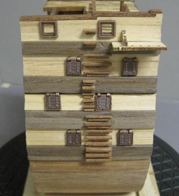
99, 100 & 101 - Gun ports, frames and covers
Photo 48

102 - Side pin racks
H - Belaying pins
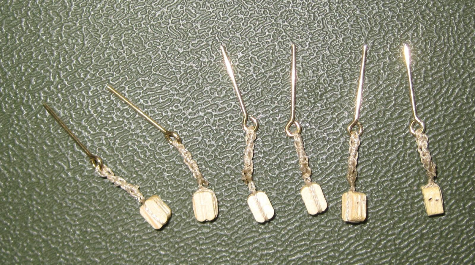
Photo 49
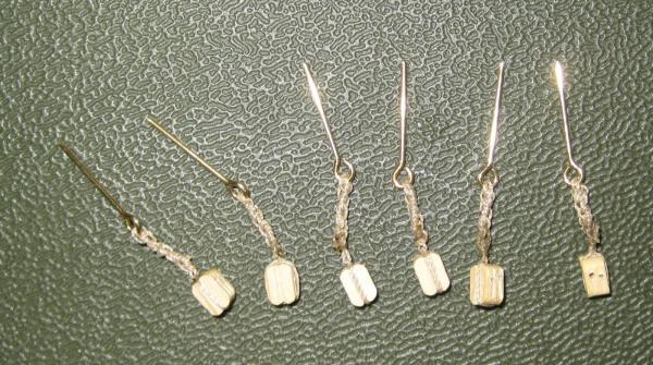
Deck Pulleys before installation
Photo 50
B - Eyebolts
C - Slings
E - 4mm Pulleys
Photo 51
F - 5mm Clump block
G - 4mm Clump block
103 - Clump block slings
104 - Chain plates
105, 106 & 107 - Loft
108 & 109 - Mainmast rail & columns
110 - Ammunition
111 & 112 - Waist stairs
-
Folks
Thank you all for your great feedback. I now have access to more plans that I could imagine and I am sure I will find the exact one I am looking for.
Daryl
-
Hi
I am also interested in building a junk/sampan from scratch, but I am having a lot of difficulty in finding any plans. If anyone comes across some I would really appreciate it if you could let me know.
Daryl
-
Everything is running nice and smooth at present. This entry covers steps 84 - 98.
Photo 41
84 - Interior Bulwark lining and
85 & 86 - Pin racks
Photo 42
87 - 1st battery rubbing strakes and
88 - Exterior lining
Photo 43
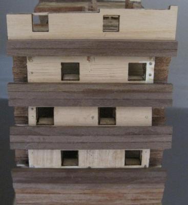
89 - 2nd and 3rd battery rubbing strakes
Photo 44
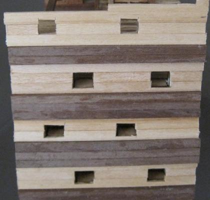
90 - Exterior lining of batteries with rough cut out of gun ports
Photo 45
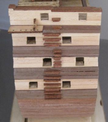
91 - Gunwales,
92 - Waist beam,
93 - Channels,
94 - Channels brackets,
95 & 96 - Small and Large ladder bases and
97 & 98 - Small and Large rungs
Photo 46
Whole exterior surface sanded and varnished.
-
And yet another small problem. I ran out of 1x3 Ramin deck planking halfway through the 3rd battery deck. The instructions state that I needed 68 1x3x90 to do the job when in fact I needed 76. I then checked all decks and found that I used more on each than the instructions stated. Unfortunately I was not counting but just laying them down. It just meant another drive to "Float a Boat" where I was able to purchase some more decking and get on with the job. I contacted OcCre but this time there was no response. I think I may have complained just one to many times.

Back to the build.
Believe it or not, but I am enjoying the build. I quickly forget the problems as I find ways of fixing them so they are not a long term issue.
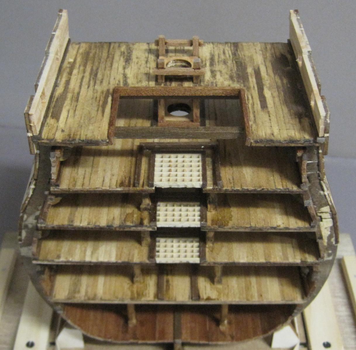
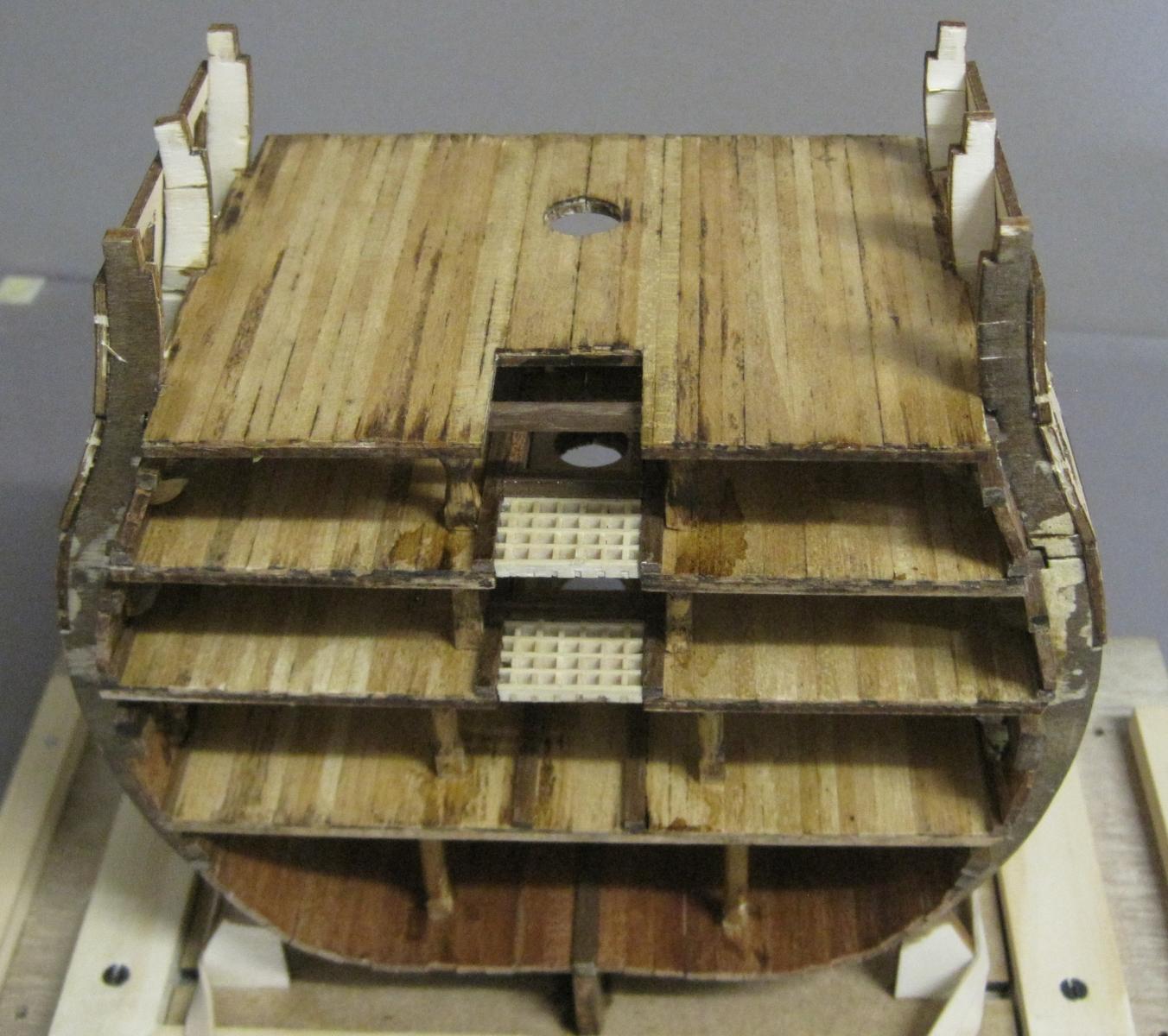
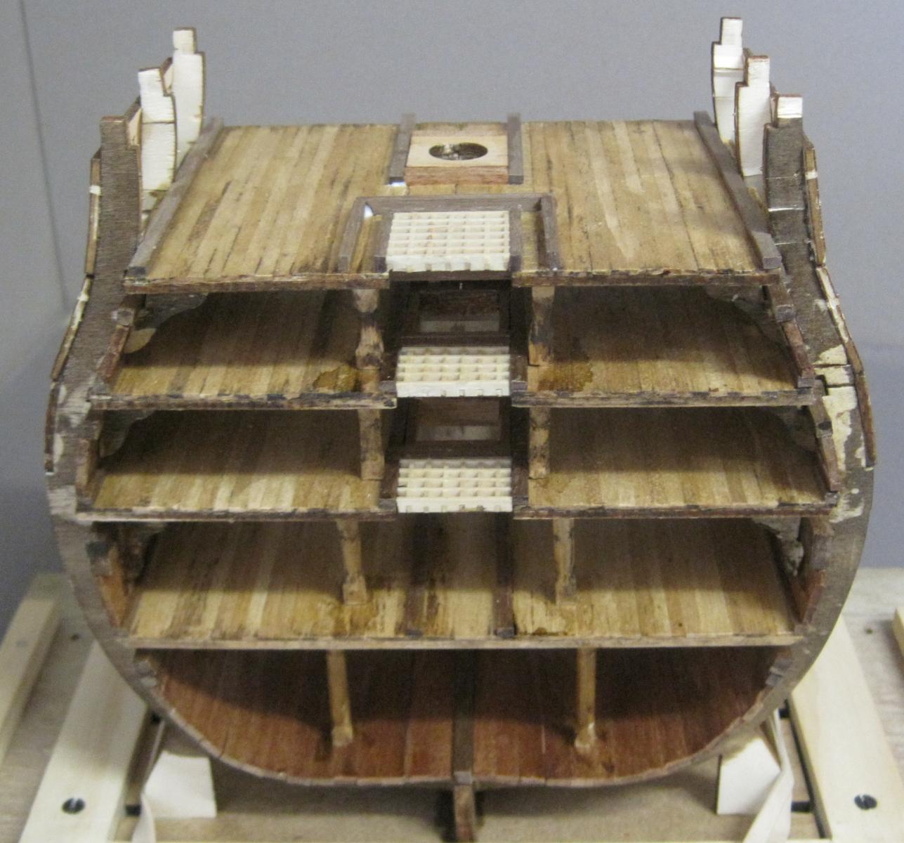
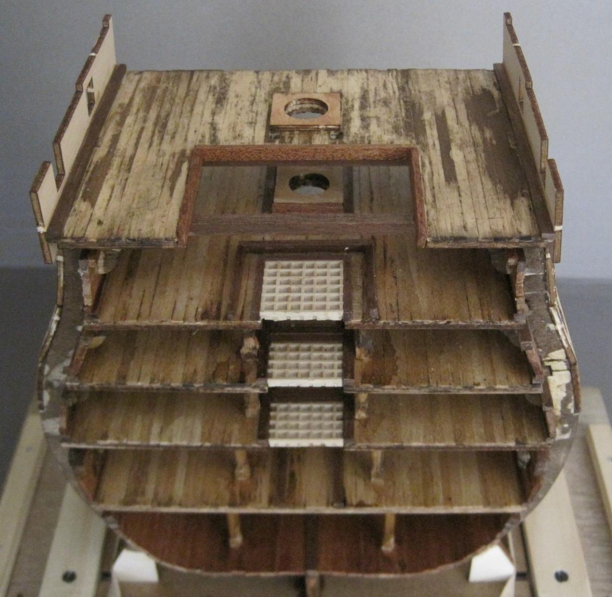
This entry covers steps 59 to 81.
Photo 37
59 - 3rd Battery deck
60 - Deck planking
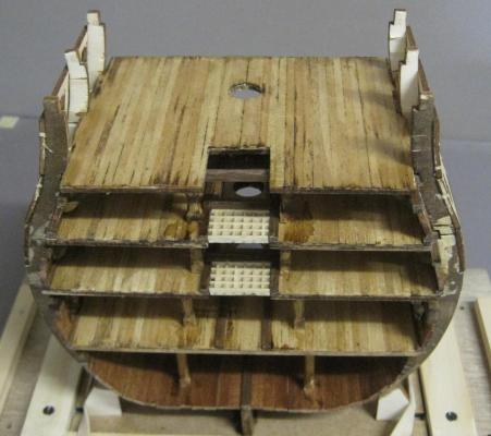
Photo 38
61 - Waterway
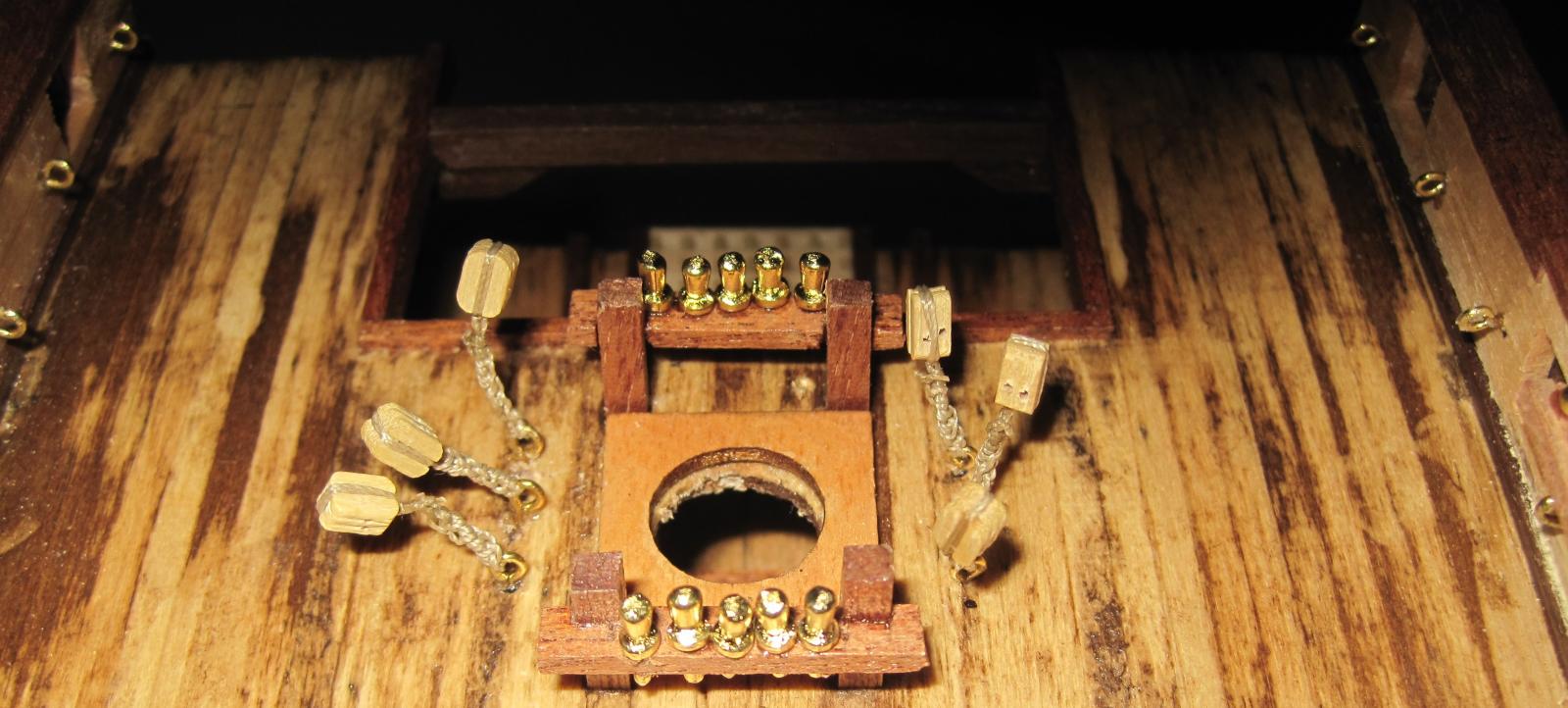
62 - Mast tabernacle
63 - Crossway battens
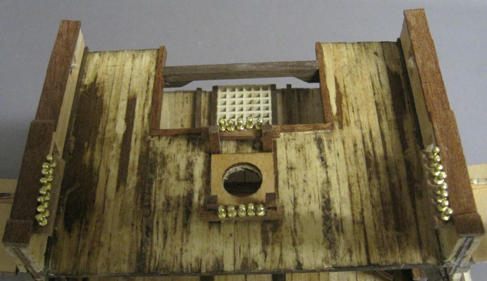
64 - Grating
65 & 66 - Coamings
67 & 68 - Ammunition frames
69 - Battens
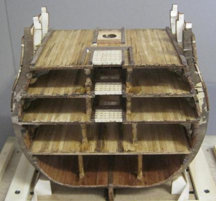
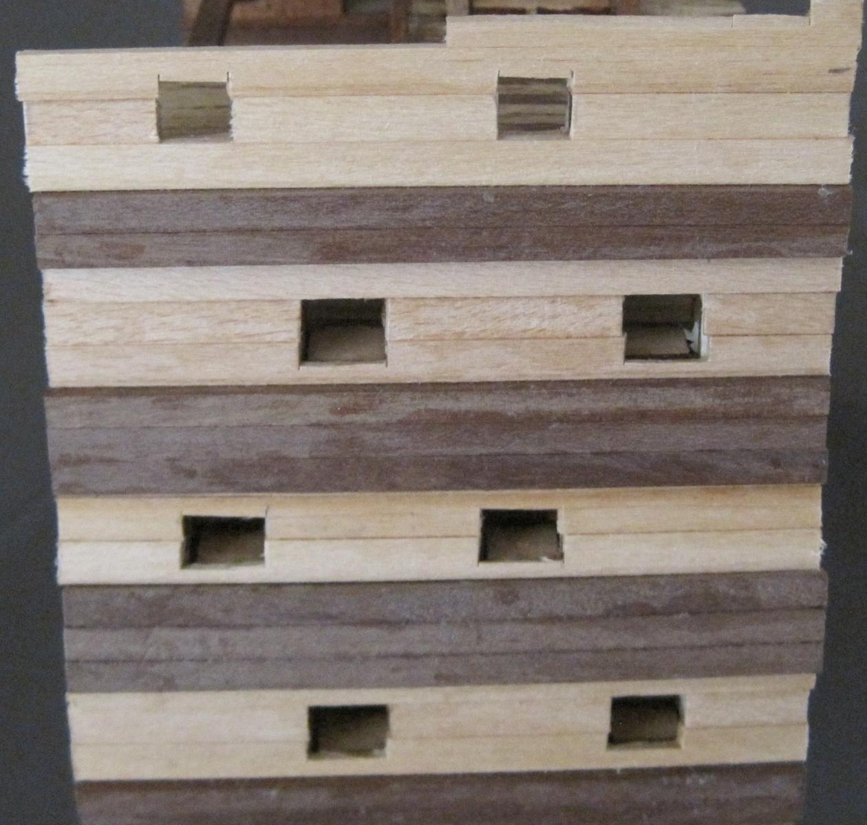
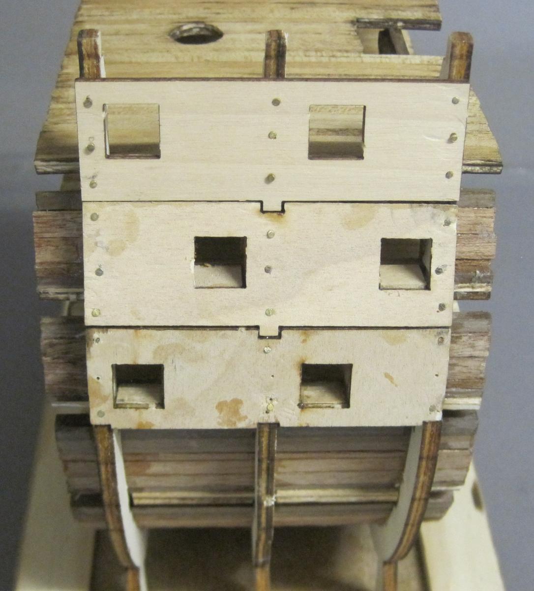
Photo 39
70 - 3rd Battery gun ports
71 - Interior lining
72 - Gun port bases
73 - Gun port sides
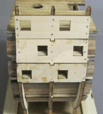
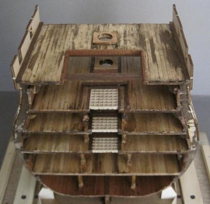
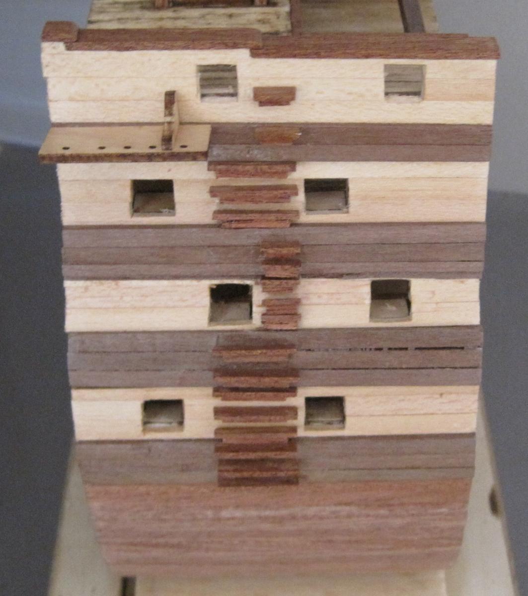
Photo 40
74 - Beam rests
75 - Deck beams
76 & 77 - Bracket frames
78 - Deck planking
79 - Mast tabernacle
80 - Bulwarks
81 - Waterway
82 & 83 - Frames
-
The 2nd Battery deck has now been completed and the 3rd Battery deck commenced. I had the same problem with the Gun Port bases as I did on the 1st Battery deck, but it was easy to fix.
What's been done recently.
Steps 44 - 58
Photo 34
44 - Waterways
45 - Mast tabernacle
46& 47 - Hatch coamings
48 & 49 - Battens
50 - Grating
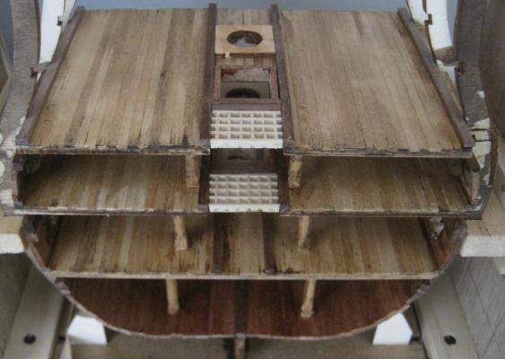
Photo 35
51 - 2nd Battery gun port
52 - Interior lining
53 & 54 - Gun port bases and sides
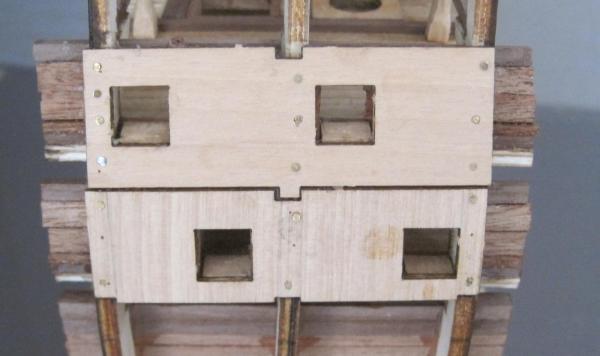
Photo 36
55 - Beam rests
56 - 3rd Battery beams
57 - 2nd Battery columns
58 - Bracket frames

It wont be too long before I have to remove the supporting feet from the frame which will mean that the existing jig will become obsolete. So I am now looking a designing a new jig that will hold the hull steady using the keel and the gun ports as support points so that I can have the keel perfectly stable for doing the rigging. I have a "lazy susan" that this new jig will be mounted on so that I do not have to lift the jig & model up to change positions when working on it. It just makes it a lot easier when you want to view the model from different angles to see how all the alignments are.


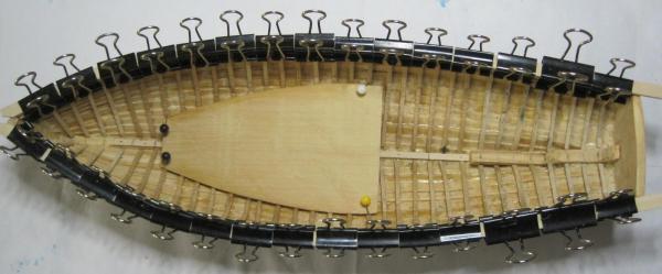
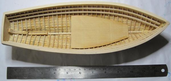
Viking Knarr by Daryl - FINISHED - Dusek - Scale 1:72
in - Kit subjects built Up to and including 1500 AD
Posted
Wishing all forum members all the best for 2015 and I hope you continue to have fun building your models.
To start the year, I will be building a very small Viking Knarr for an elderly friend of mine. It is a Dusek model and, due to what I have found in researcing Knarr's, it will have a few modifications.
The following photos are of the kit as it arrived.
The kit contained everything it said it did, and from the first inspection, the parts look like they are in very good condition.
The Plans are well drawn, but as I have been advised by Dusek, they are "simplified" drawings. what this means is that in some places they do NOT represent the actual shape of the part. That surprised me as I would have expected them to be 100% accurate. Contact with Dusek was immediate and well received.
As you can see in the Parts photo, there does not seem to be too much work on this model. But, you never know.