


cdrusn89
-
Posts
1,598 -
Joined
-
Last visited
Content Type
Profiles
Forums
Gallery
Events
Posts posted by cdrusn89
-
-
Thanks Dfell - here are some more pictures.
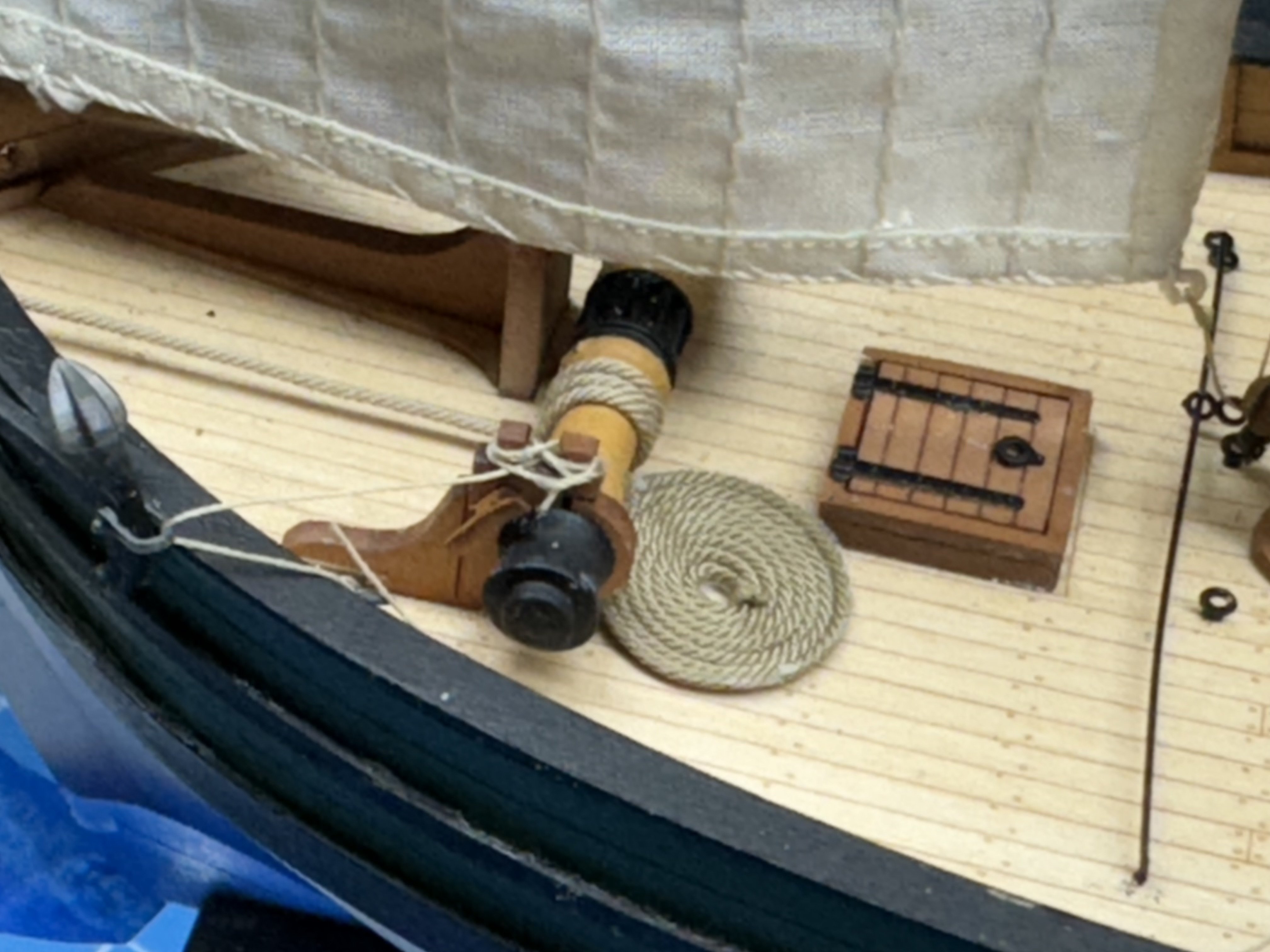
I am still "running around" securing the running rigging and adding some coils of line in places. I had to rebuild my line coil jigs because everything I have is too big.
Here is the main sheet tackle (with the tiller finally added).
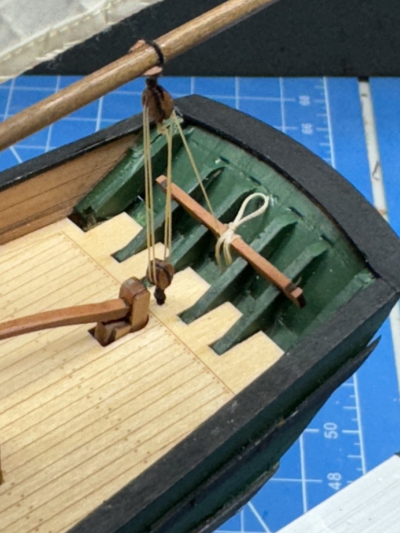
I decided to show the boat stowed on deck so I built a little "cradle" and tied the boat to it. At the moment it is just sitting on deck (no glue) as I am not sure where it should go. I think it has to go aft as with the cradle it doesn't really fit along side the fish hatches.

I also decided to house the anchor and provide some rode on deck. I assume these boats did not carry a great deal of anchor rode as they probably only anchored in fairly shallow water - like to spend the night rather than go in with a bad catch.


Not the most seaman like securing of the lines but getting that polyester line to act the way you need it to is a challenge.
-
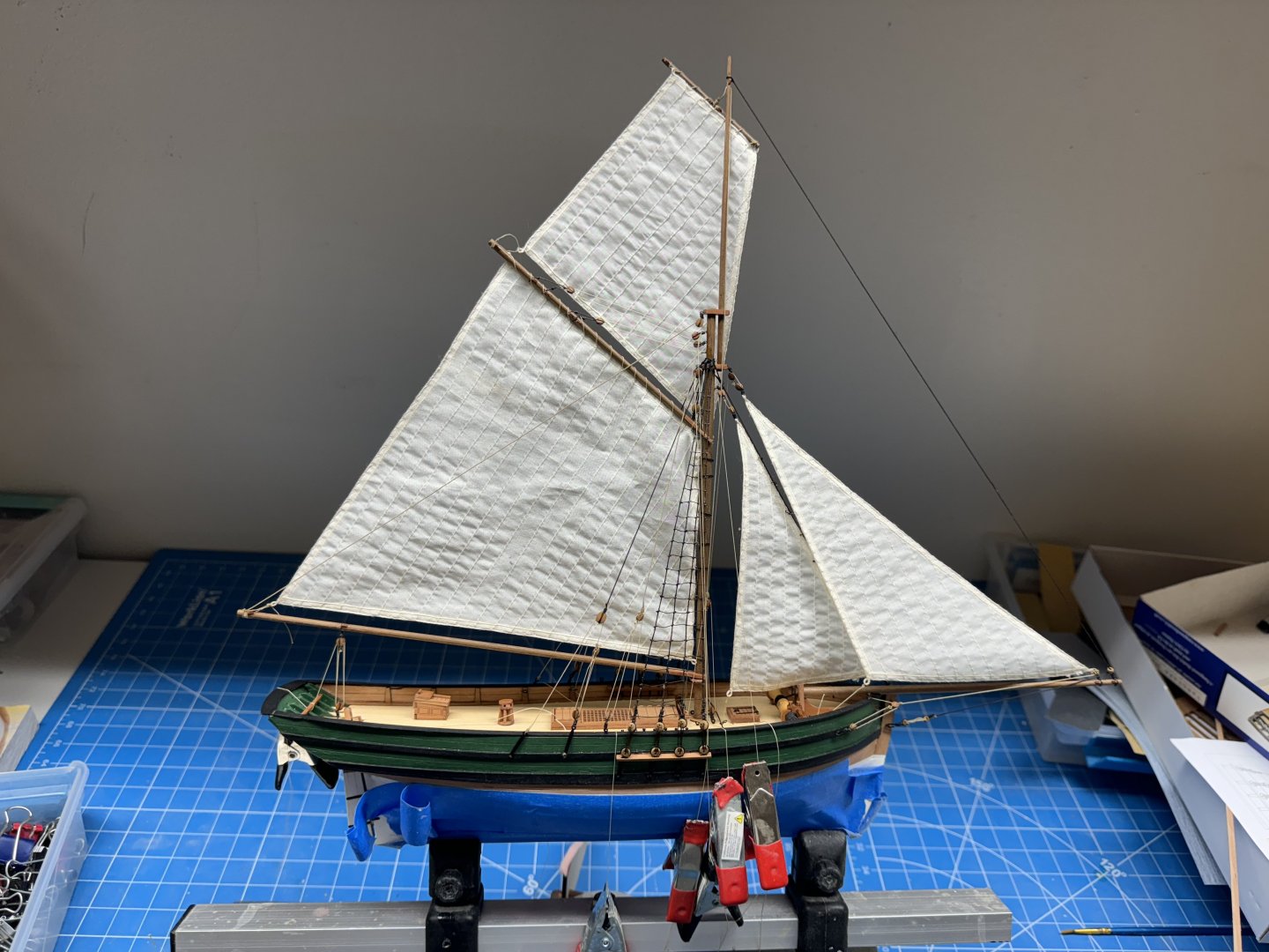
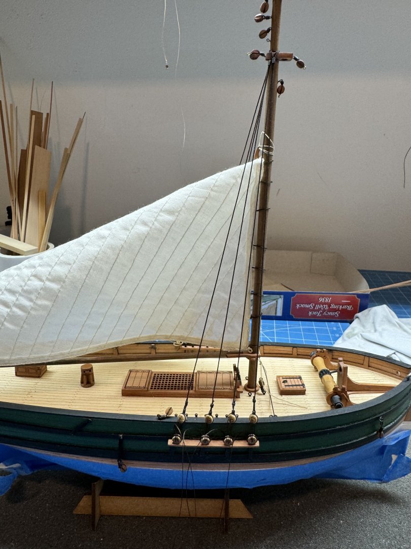
Saucy jack is almost done.
The clamps hanging down are holding some of the lines that have yet to be secured. Getting the line around the cleats and belaying pins is not that easy and manipulating to follow the examples on the drawings is impossible (for me). I am going to make up some coils of rope to hide the mess around the cleats/pins but that may take a bit of time as I have no experience creating them using 100% polyester line. I wonder jsut how much "extra" line they would have laying around on a commercial fishing boat - I would expect not what you would see on a man-of-war but...
I also have some paint touch-up to do but will wait until I have the lines secured.
- JacquesCousteau and phyla
-
 1
1
-
 1
1
-
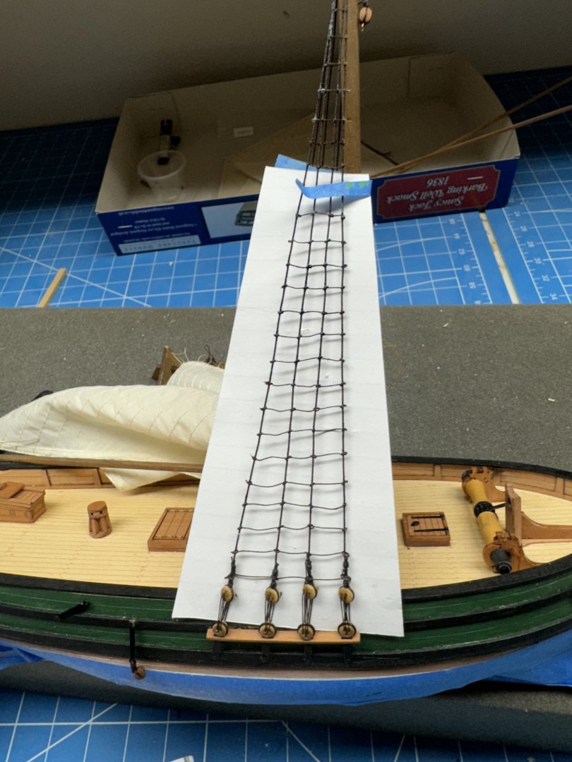
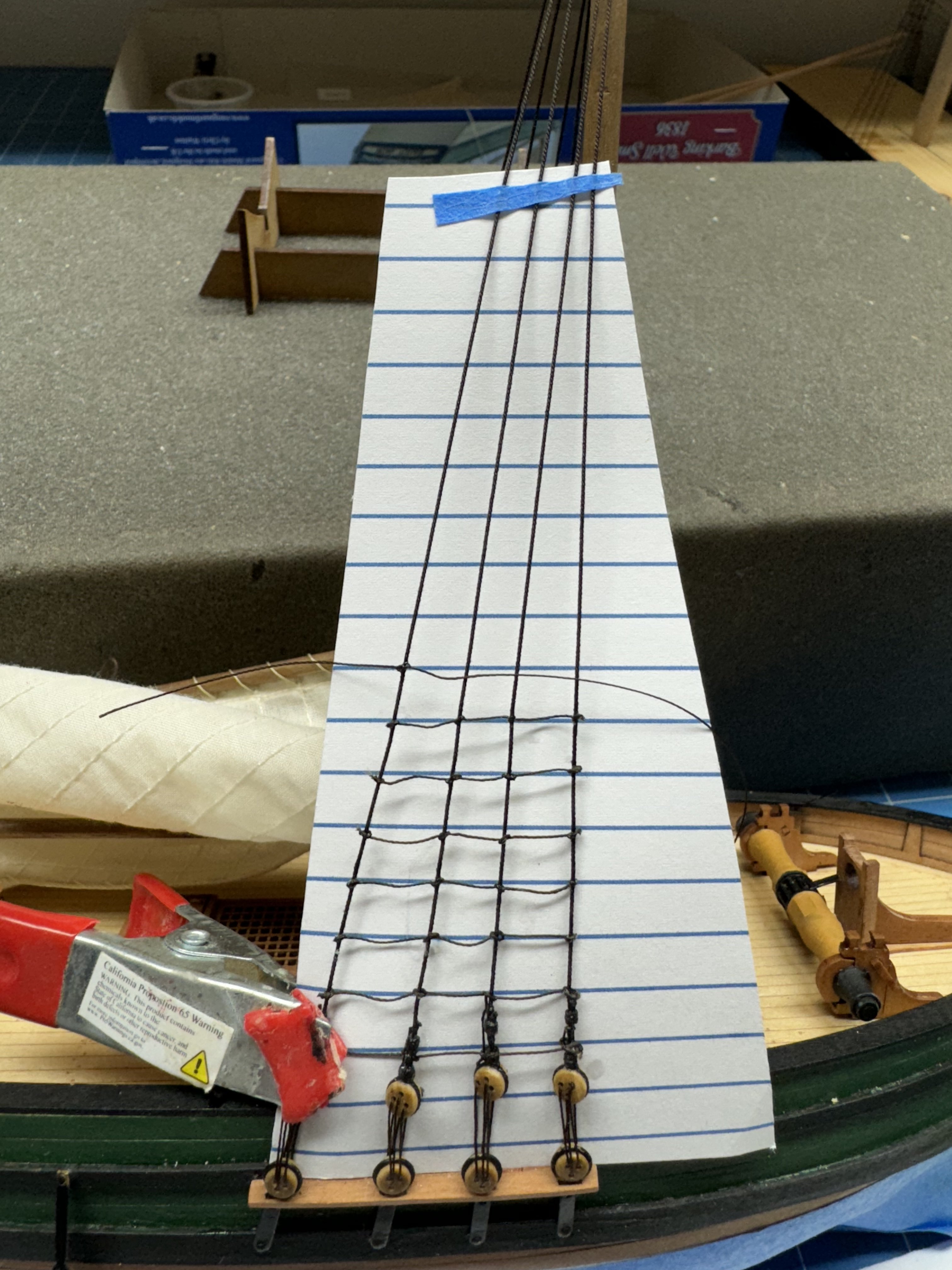
Starboard side ratlines complete.
Not the neatest job I every did and I think I might have gone with the .008 Syren line given the above info.
When I got to the top three or four rows, where the shrouds are very close together I put a drop of PVA/H20 on each shroud and coaxed a short length of the polyester across the shrouds in a more or less horizontal line. When the glue dried I put a drop of thin CA on the part sticking out on each side to (hopefully) stiffen the polyester and make cutting it off easier.
Seemed to work okay but on port side I am going to try "Tacky Glue" instead of the PVA/H2O for the upper ratlines. I may start at the top and see how far down it looks reasonable without an obvious "knot" at the junction.
-
Thanks Jacques - if you are retired and have nothing better to do (it is really hot here in Florida at the moment) then working on your ship model(s) is what you do.
I have done some research and a source on MSW quotes Lee's Masts and Rigging of English Warships (I have a copy coming from eBay) that ratlines were 1.5" circumference no matter the ship size. That would seem to stand the idiot test since the object of the ratlines is to get the sailors up and down the masts. And sailors are pretty much a common size there should be a "best" size for the things they step on to get up and down the mast no matter the size of the ship.
1.5" circumference works out to .477" (divide by pi if I remember my geometry correctly) which at 1/64th scale would be 0.0075" 0r 0.1898mm.
Assuming the above reference is correct (and I have no reason to doubt it) then using .008" line would be "okay" for an English warship like Sphinx. Maybe not so much for a small fishing boat like Saucy Jack.
-
While "playing" with the polyester thread (line?) I noticed that it has some twist "built in (as does any thread made from twisting smaller fibers together). This twist made the line want to go in a direction different from what was desired on what seemed like many occasions. I worked out that a length on about 200mm was the "best" (for me) which is long enough to have plenty of "extra" line to grab a hold of but not so long as to get caught on everything around. So I cut several lengths and hung them mover the workbench edge to see if at least some of the twist would work itself out.
I am not sure things are any better but I feel better so that is what counts.
Anyway I am about half way up the starboard shrouds. I decided to use overhand knots as I know how to tie them without consulting the drawing every time and I think the leave less of a "bump" at the junction with the shroud.
I also am using thin CA to "fix" the knots as it is faster and it stiffens the thread which makes it easier to trim off the excess.
I probably should have consulted the drawing after I made my spacing template as I am going to have several more ratlines than is shown on the drawing. I guess I better redo the template if I intend on using it on Sphinx.

-
Starboard side completed and all the deadeye lanyards have been glued down.
Time for ratlines.
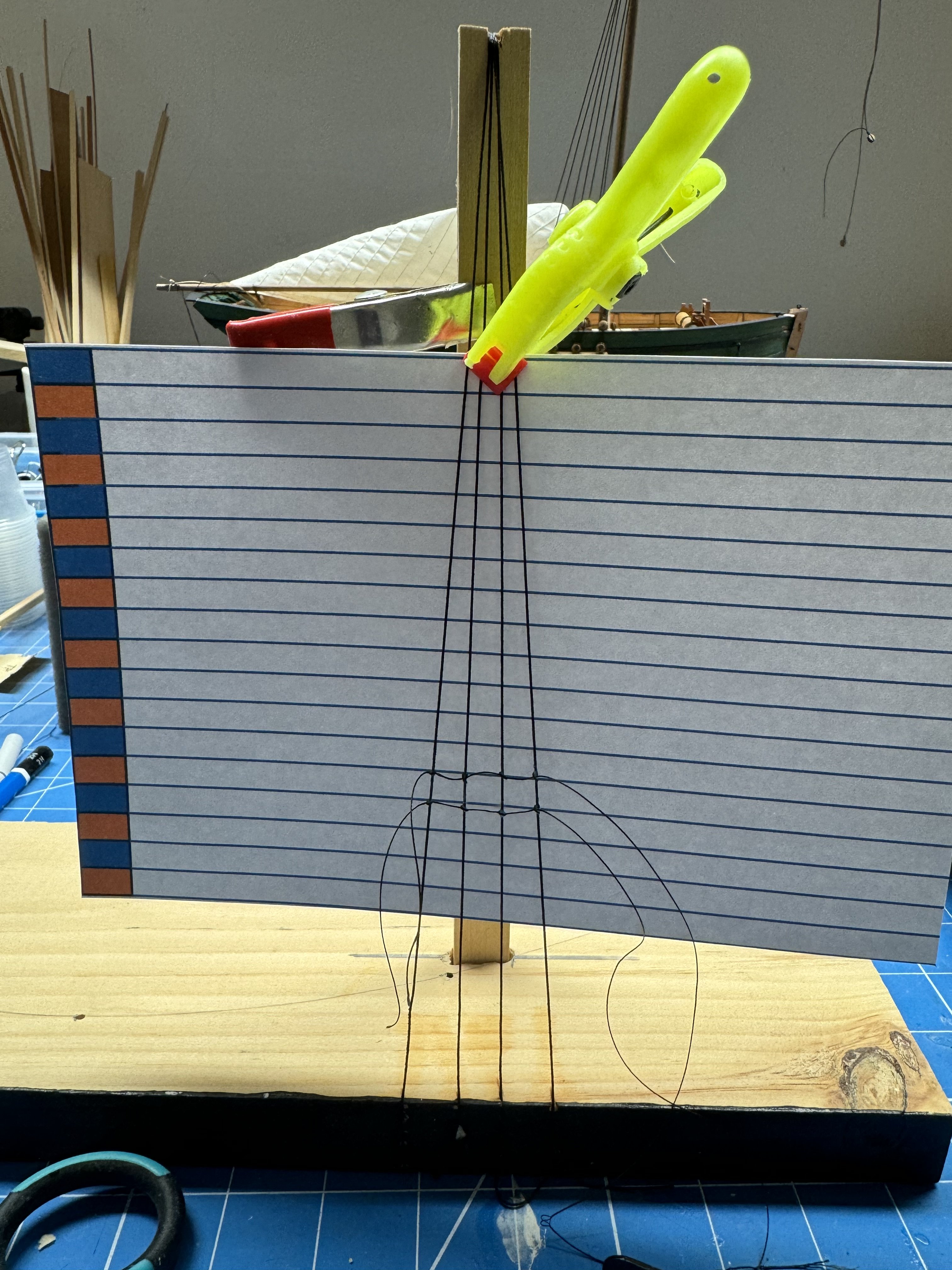
Because it has been a few years since I had to "do" ratlines I decided that maybe a little practice was in order.
So I built a little "replica" of the SJ shroud configuration and tried a few "practice" ratlines using the polyester line referenced above. I used PowerPoint to create the ratline template and saved the file as I suspect the spacing will be very similar on other 1/64th scale models.
I did two rows but had to look at the drawing provided of how to tie a clove hitch at least ever time i had to tie one, sometimes more than once per.
Anyway I dabbed each junction with 60/40 PVA/H2O and it is drying now. Will trim the ends when it dries and see how it looks. Seems to be going okay with the poly line but the PVA needs to hold the knot or it is game over.

-
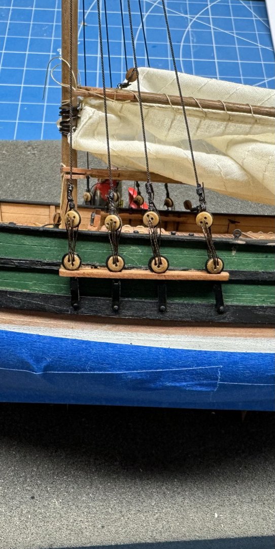
Port side deadeye lanyards completed.
The deadeyes could be a little closer to the same height but since they are in pairs if you move one up the other moves down so.... And I managed to scratch up the sides behind the channels reaching with the tweezers to grab the line coming through from outboard. Maybe I will try and get back there with a small brush - and maybe not.
The lanyards look a little "thin" to my eye but I think the Guttermann Tera 60 I used is slightly larger than the Guttermann CA02776 that comes with Sphinx and I assume it is the same material on Saucy Jack although it does not come identified my manufacturer in the SJ kit.
Also another hit on the polyester lanyards is they seem to have less ability to resist the twist in the shroud line and thus the deadeyes appear even more out of alignment. On a larger ship there is a wooden batten that runs across the shrouds just above the deadeyes (which I am sure has a particular name but...) that helps to correct the deadeye alignment but not on Saucy Jack (although adding one would not be terribly difficult). Admittedly what I have used before for lanyards (Syren .008") is considerably thicker but at 1/64th has not seemed totally out of scale on other models although that is a pretty small sample size - at least for me. I have built only two other models with this deadeye/shroud configuration, both 1/64th scale (Niagara and Pride of Baltimore)
On to the starboard side to finish up and then my favorite - ratlines .🙁.
-
Starboard side shrouds completed and deadeyes threaded with lanyards although not tied off yet.
The port side has two shrouds completed and I will rig those and then tighten and tie off the lanyards one at a time alternating sides although given the dimensions of the mast and its secured well below deck the risk of distorting it is pretty small.
I should also mention that in spite of the instructions to the contrary I have not glued in the bowsprit yet - along with the tiller it is too easy to get fouled by something. Both will go only when absolutely necessary.
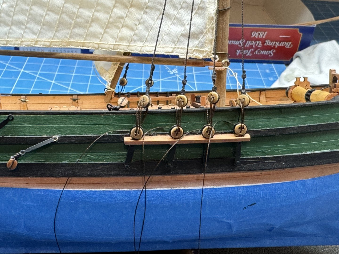
This is my first time using 100% polyester line for rigging lanyards and I am not sure I would use it again. When I get to the ratlines that will be the real test of the polyester. You have to be able to cut it cleanly with minimum "stress" and I am not sure how well it will perform.
All this in preparation for HMS Sphinx which has three masts and many more deadeyes, lanyards and ratlines.
- ccoyle, JacquesCousteau, James H and 1 other
-
4
-
Now the "real" fun.
Shrouds and deadeyes. My technique includes making the shrouds up (in pairs per the drawings) with one deadeye fixed in place and the other "adjustable" as well being able to control the overall length of the shroud my moving the adjustable deadeye.
At the top of the lower mast the shroud pair goes over the top of the lower mast. The instructions would have the top mast in place at this point as well but I think it will just get in the way and plays no part in the lower shrouds so....
Anyway that is not really the area of interest.
Down at the channels I used two pieces of .020 piano wire to make two (as identical as I could make them) "templates" for the deadeye spacing based on the drawing.
Here you can see the two wire templates fitted into the center eye of the bottom deadeye and likewise into the upper deadeye. The left shroud length was fixed before installation so "all" that has to be done is to adjust the shroud length to hold the deadeye in place. If necessary (and it usually is) I use a piece of pencil eraser to hold the upper deadeye to the template.
I have adjusted the right deadeye to tension the shroud and now a few drops of thin CA and it is on the port side for the next pair of shrouds.
- JacquesCousteau and ccoyle
-
2
-
-
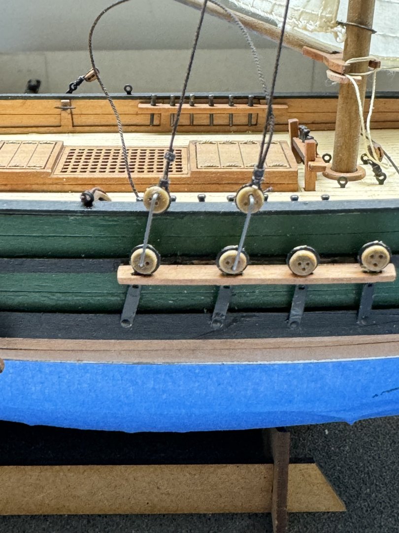
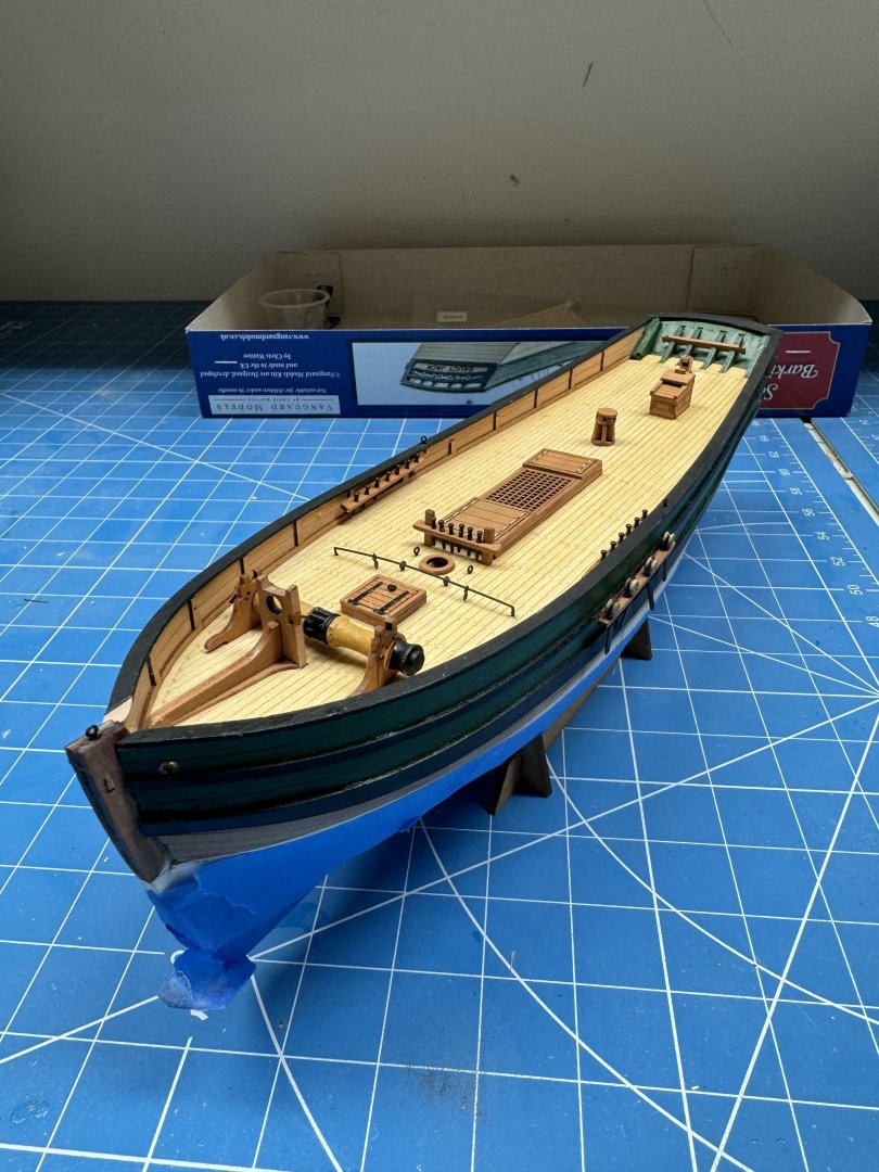
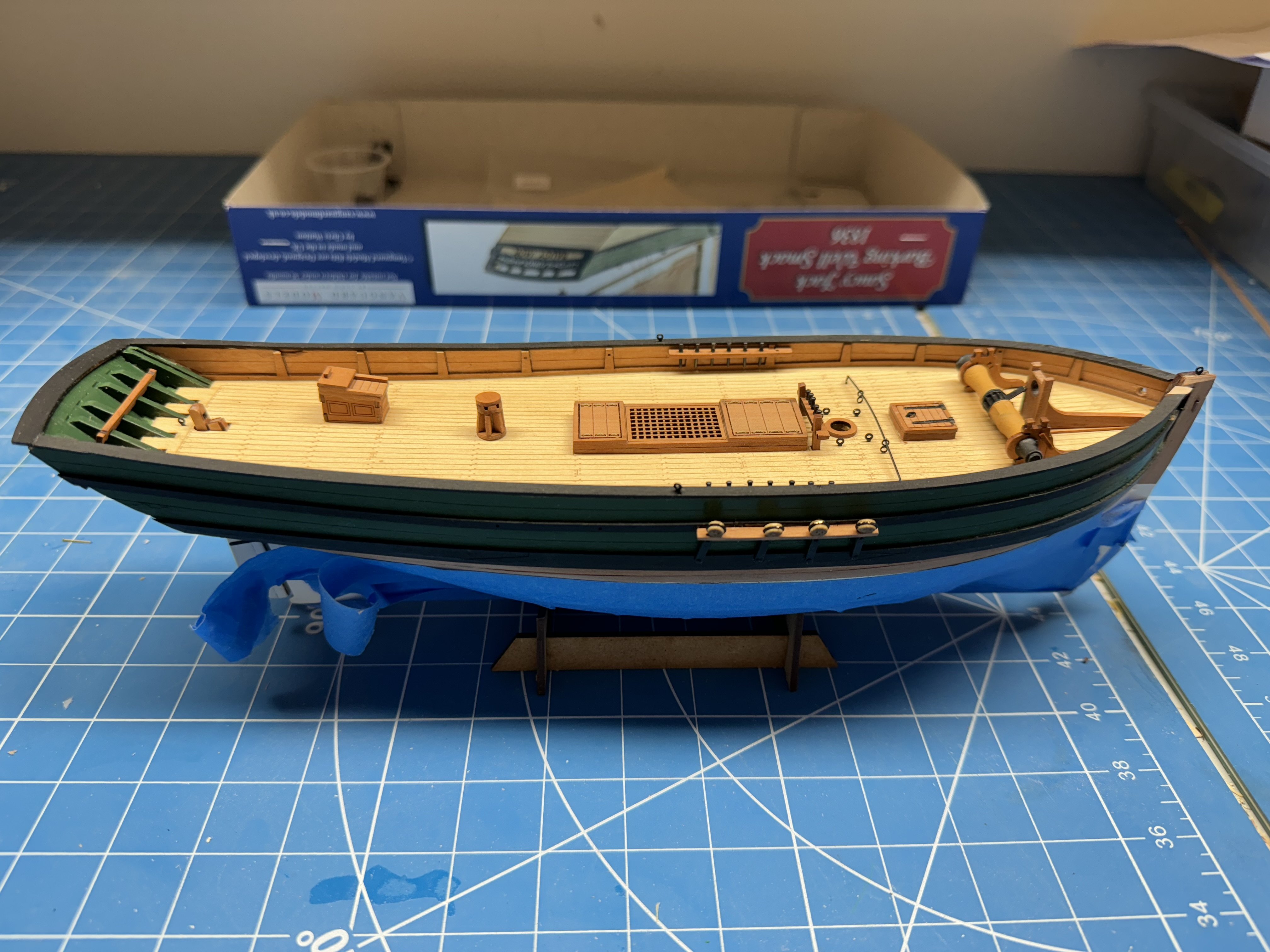
Now with all the deck furniture added. I decided to leave the tiller off until the rigging is completed. It makes to tempting a target for an errant hand or tool.
I purposely have the deadeyes tilted outboard to make threading the lanyards easier - but still not easy.

- JacquesCousteau and ccoyle
-
2
-
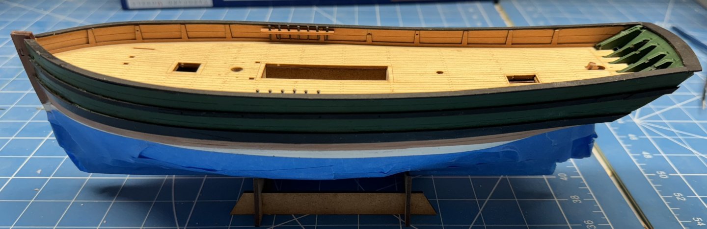
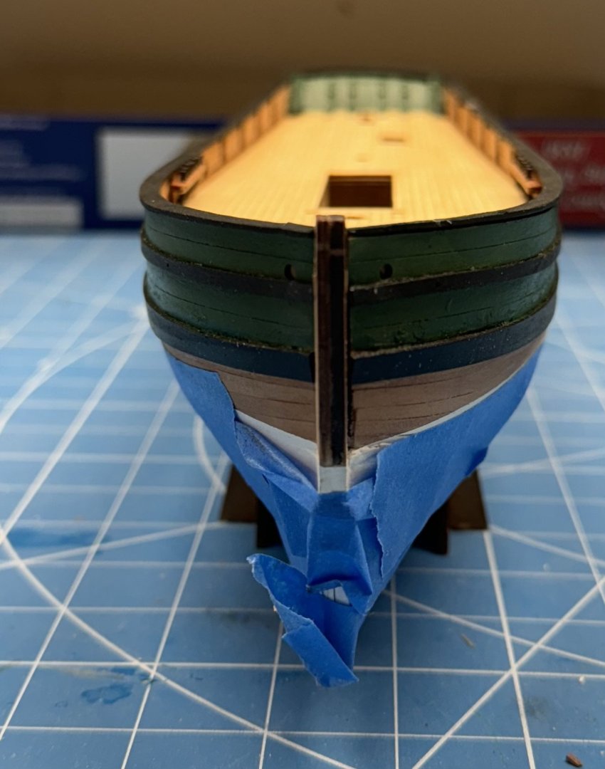
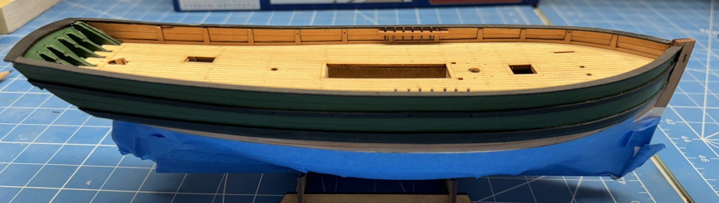
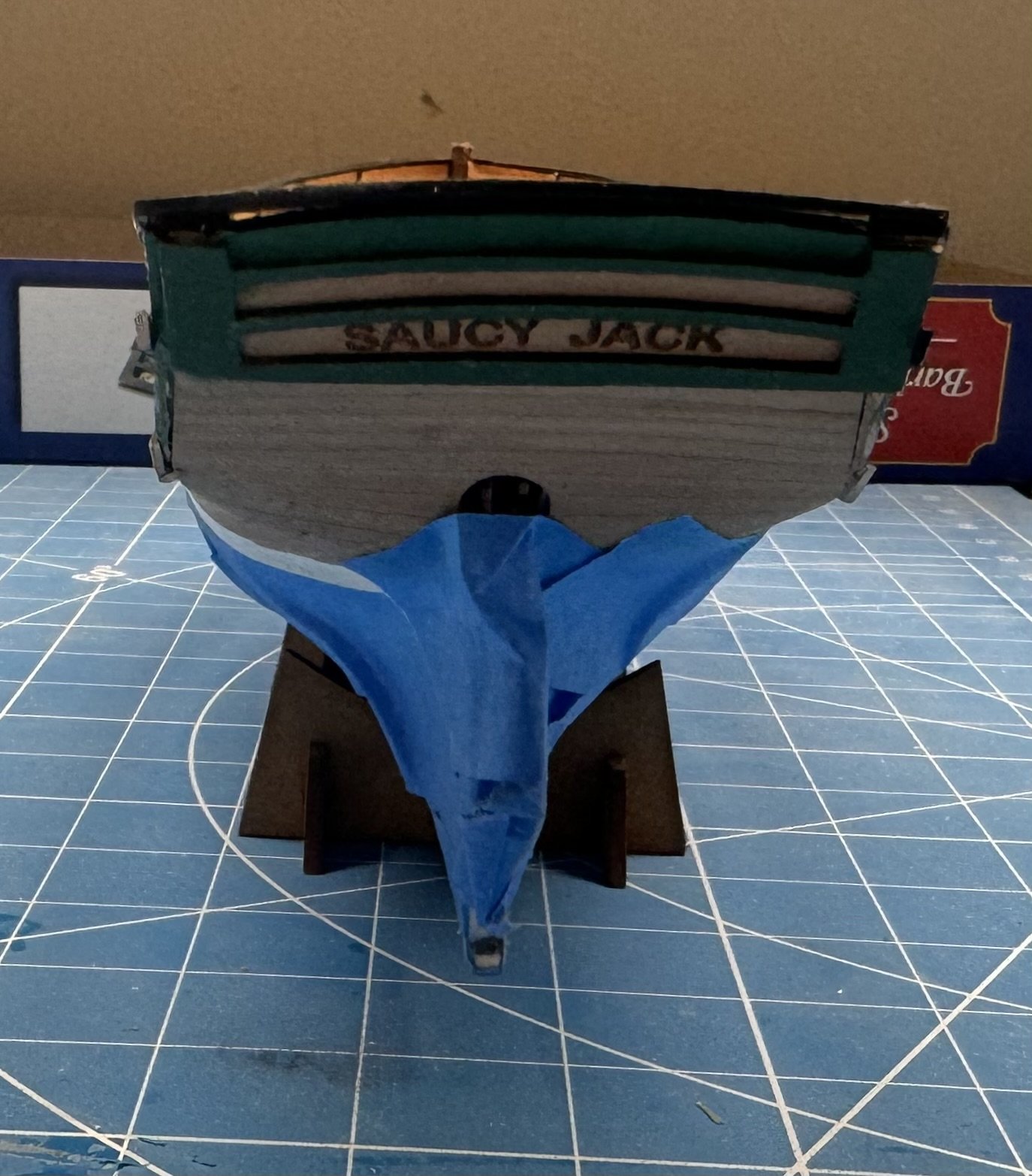
The hull is nearly complete. Just have to add the rudder and then start installing the deck furniture. FYI the blue tape is to protect the white hull from damage while it is being handled going forward. Don't ask me how I know the precaution is necessary.
FYI - I used blackened brass belaying pins instead of the PE ones included. They are actually round like the real ones.
As I mentioned previously I decided to paint the entire hull above the wales green.

-
Thanks Jacques!
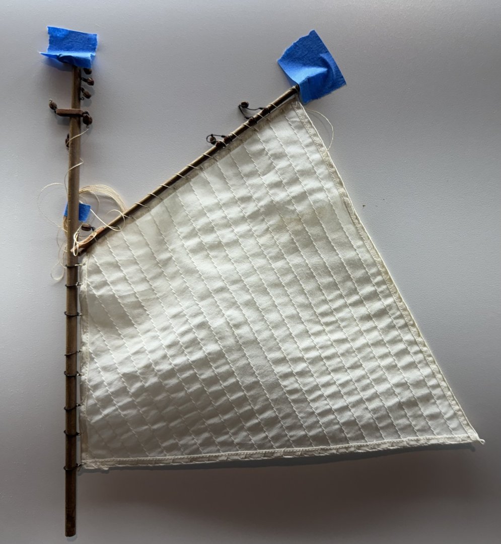
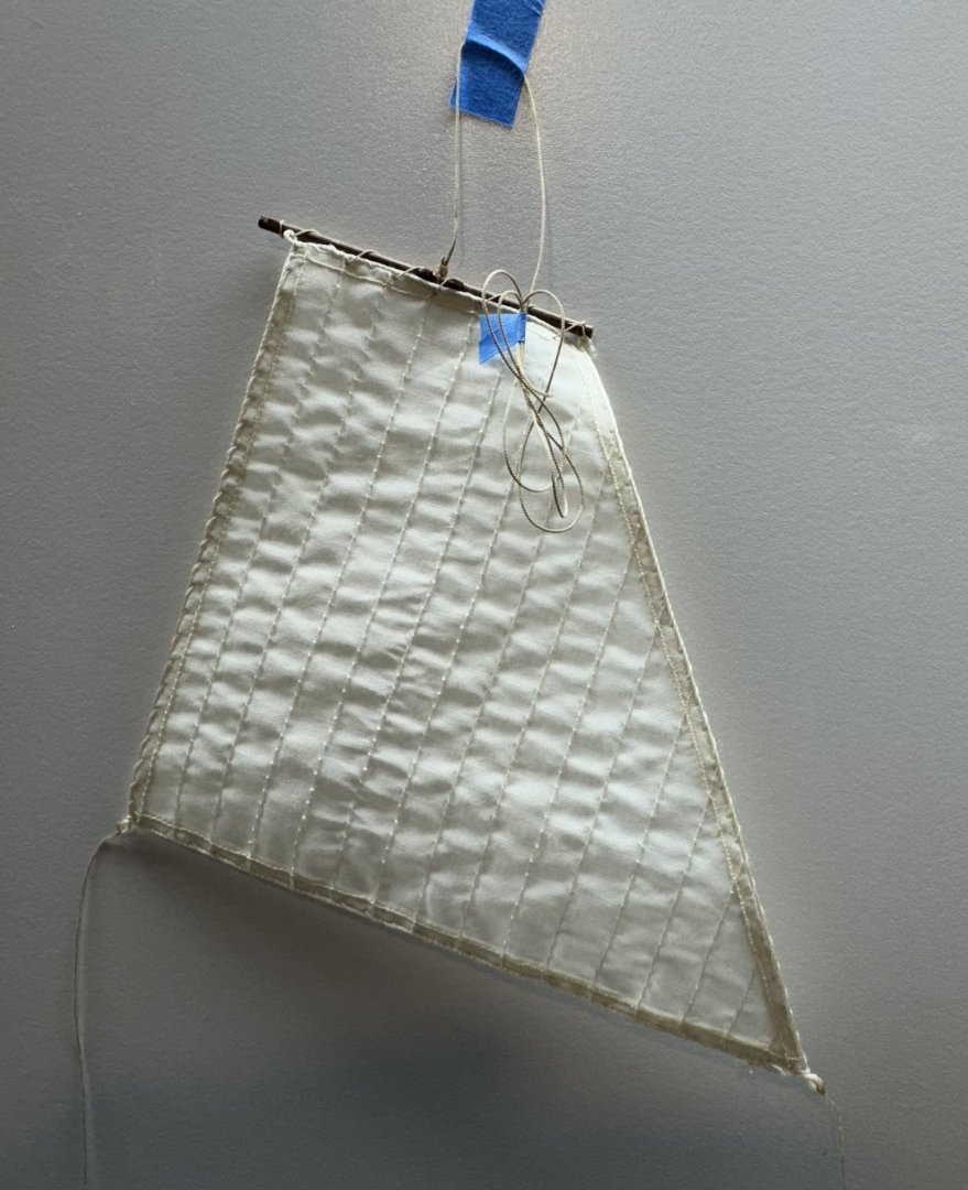
Here is the main sail mounted on the mast and gaff.
I thought it came out alright.
Only the flying jib (actually called the outer jib sail but my experience is that the most forward head sail is called the flying jib) left and it only has a block at the peak for the halyard tackle and sheet lines so I will leave that until I have the spars are in place and am really "hanging sails"..
-
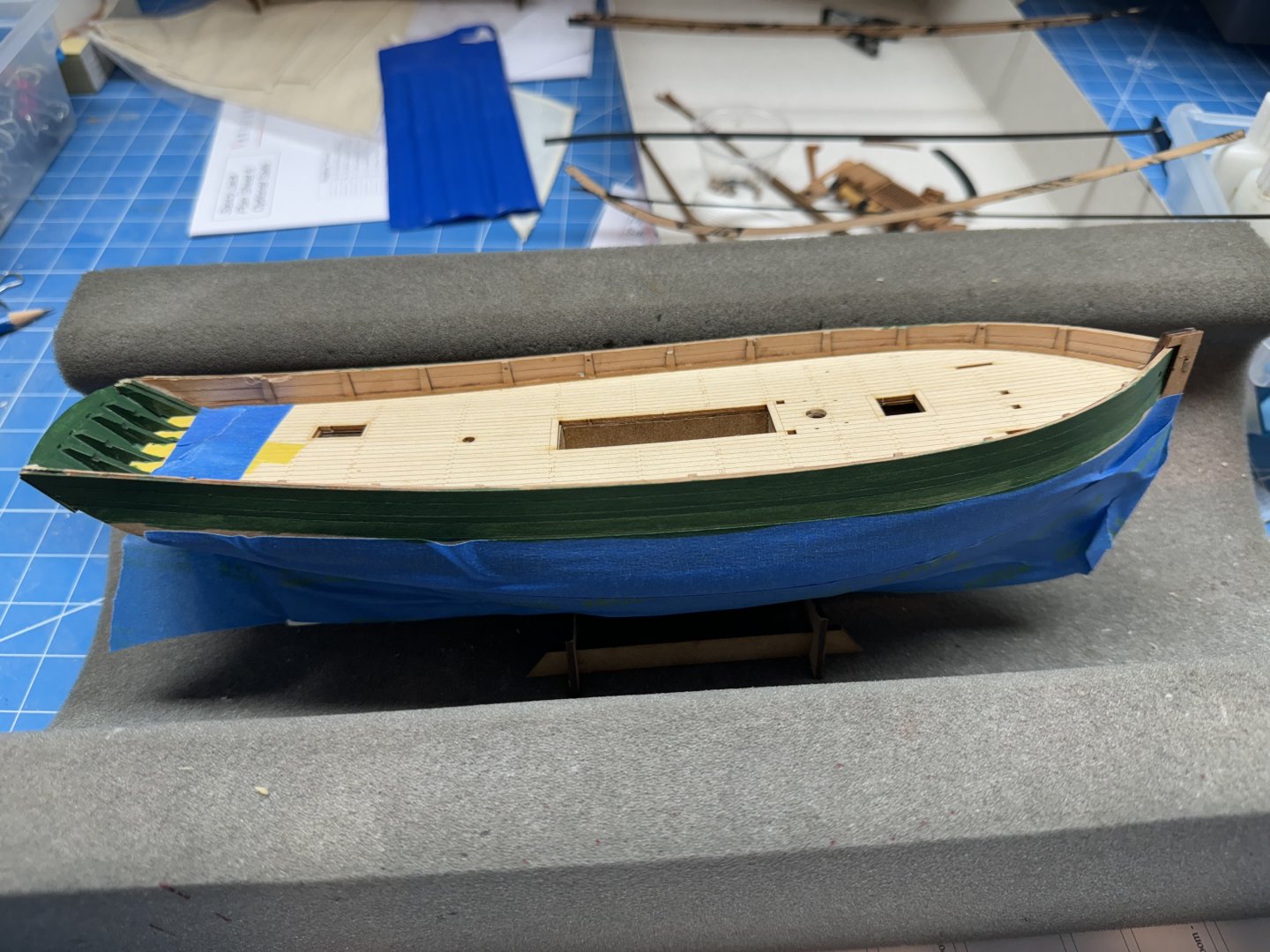
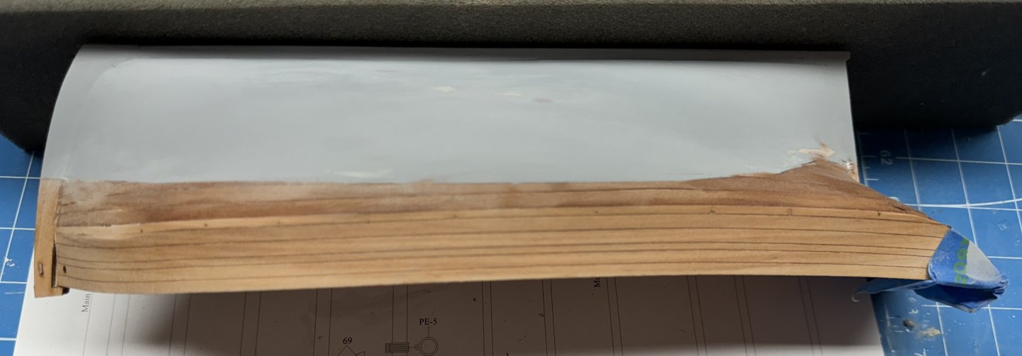
I added some filler to the seam where the "new" piece was added. I will apply a coat of green then probably need another coat.
While I had the green paint out I decided that the bare stripe I had above the wales was too thin and went ahead and painted the sides above the wales all green. I still have a strip of natural below the wales so there is some evidence that the hull was planked in the more or less conventional manner.
- DB789, chris watton, James H and 1 other
-
4
-
While waiting for the filler to dry on the transom I decided to continue the sail work on the main sail.
The main is attached both to the mast with hoops and to the gaff with lashings.
I decided to do the easier one first - hoops.
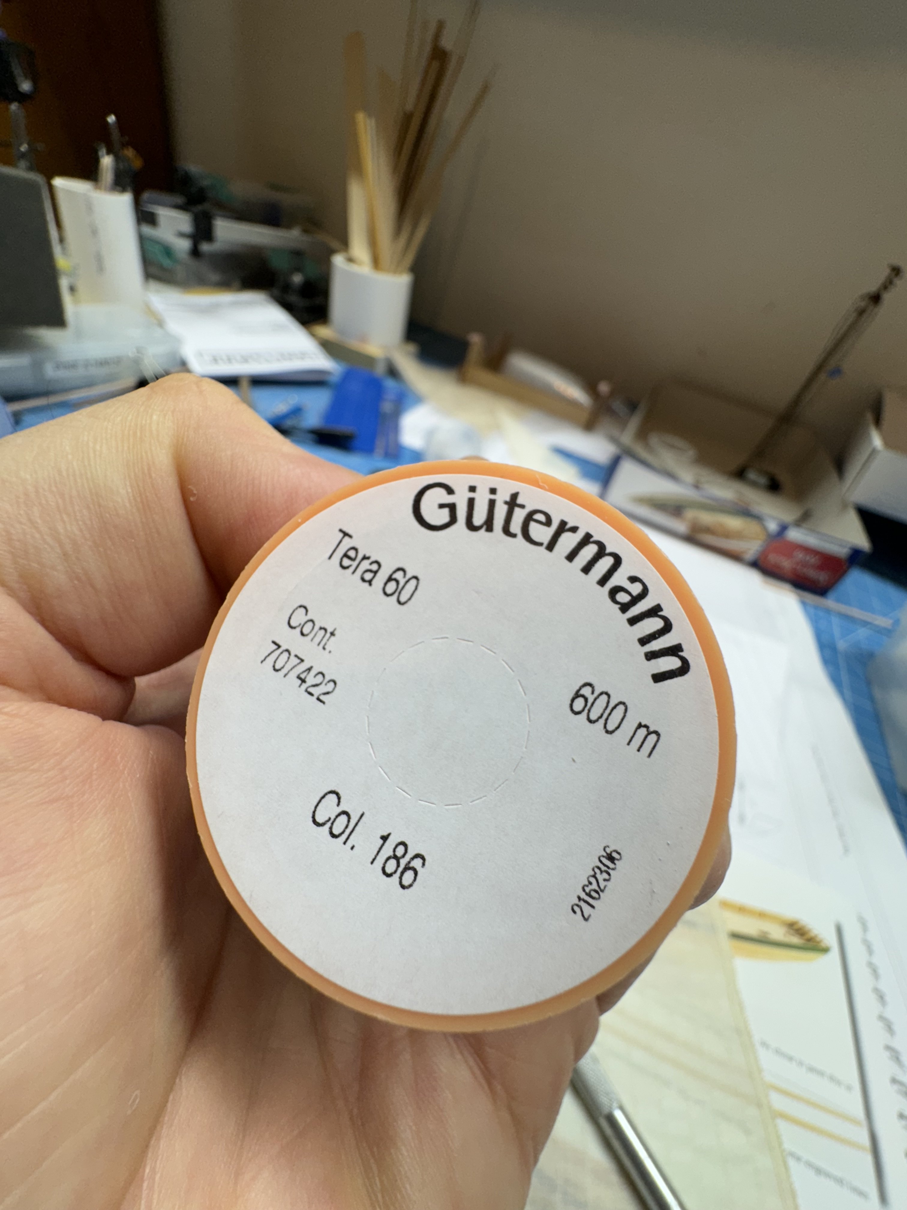
I am using the Guttermann polyester thread as a substitute for that provided in the kit as I want to make sure I have enough to do this kit as well as Sphinx And I am terribly wasteful of rigging line.

I think 600m will probably last me a lifetime.
So the mast hoops are on the PE sheet which I previously cleaned (very important to clean the brass before painting - don't ask me how I know) and painted flat black.
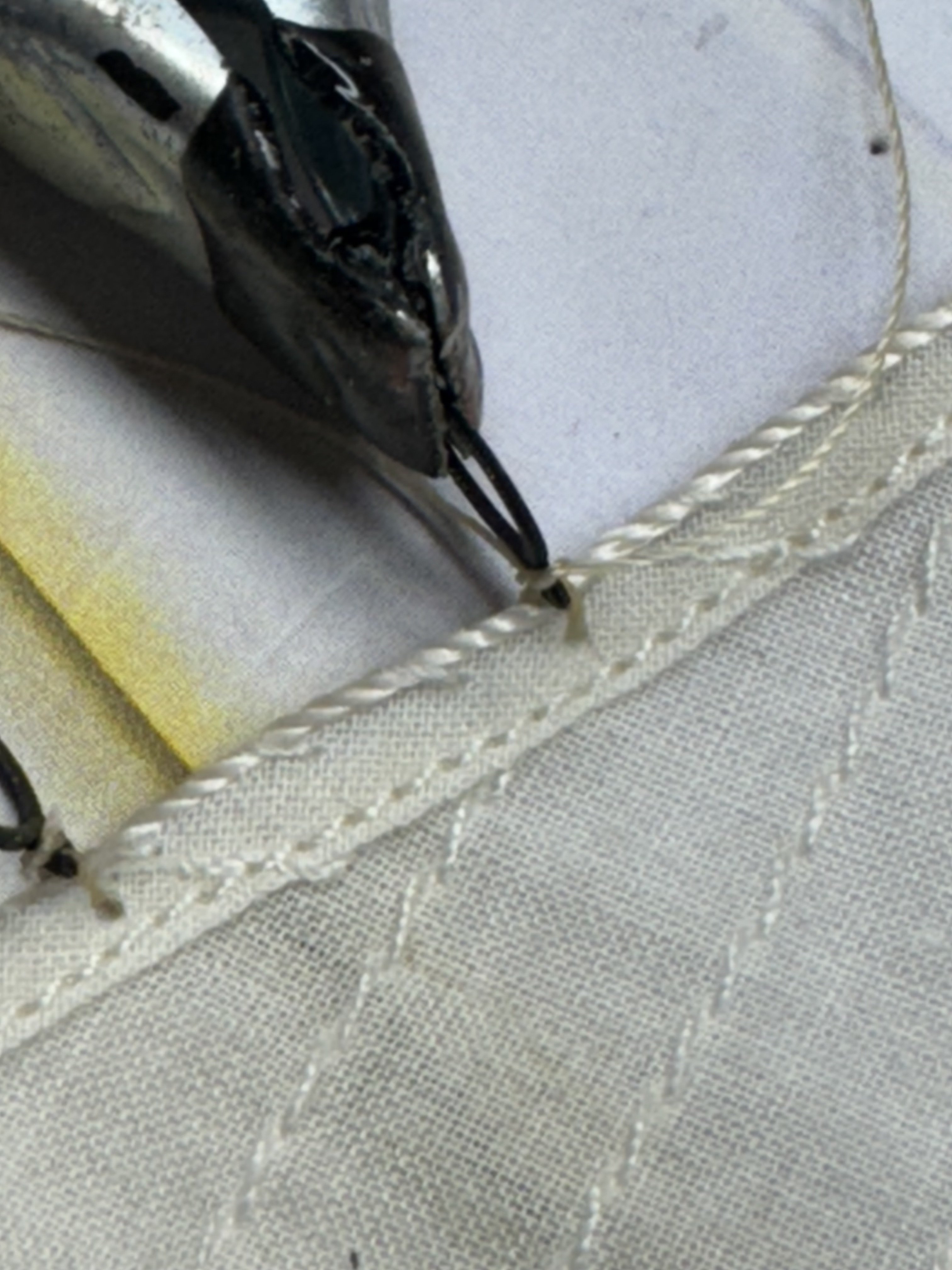
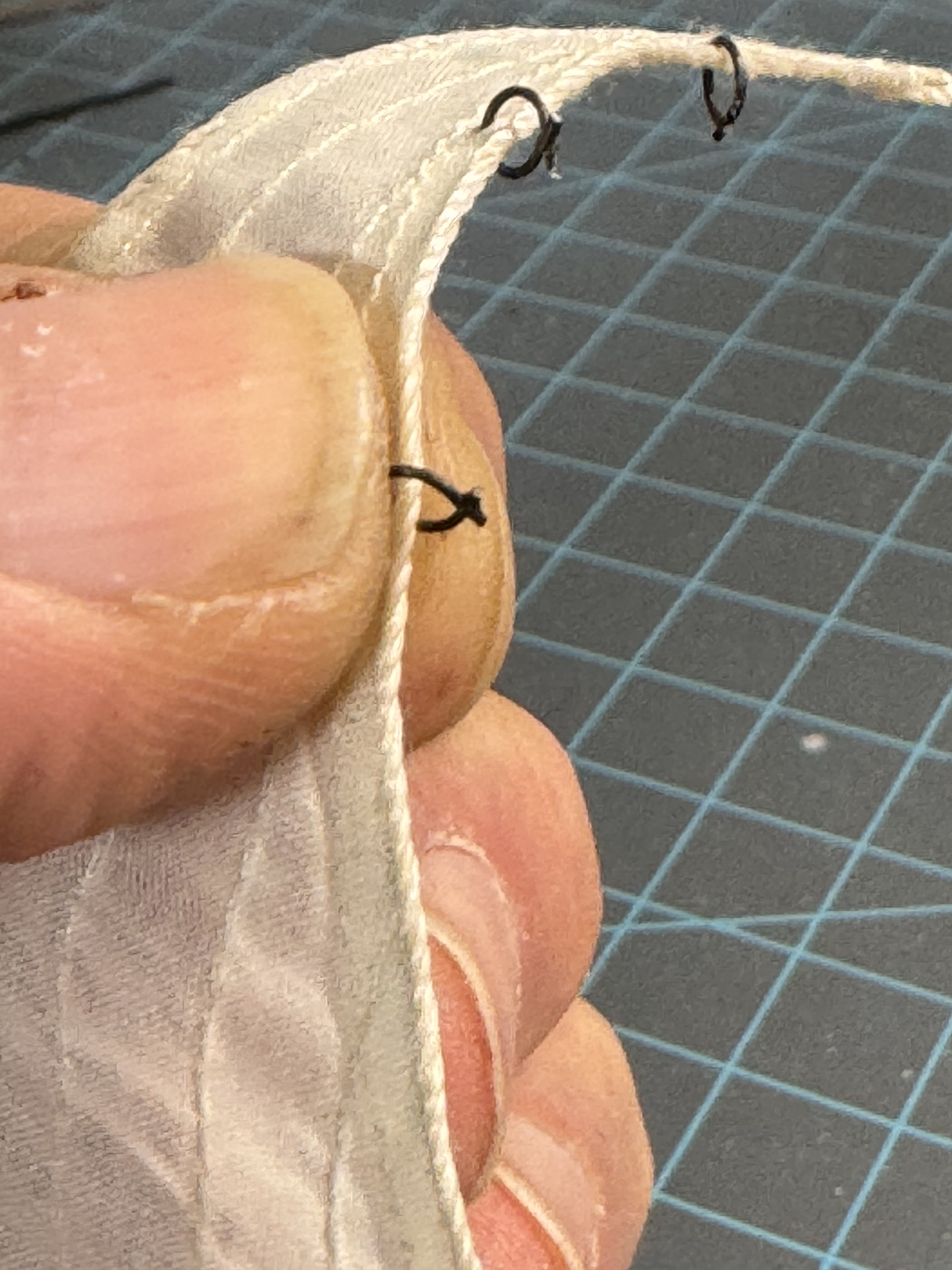
Using the drawing I determined that the hoops are 14-15mm apart and so I used a sharp awl to make a hole in the edge of the sail and threaded a piece of line through the hole. The through the hoop from the bottom with one side of the line and in from the top with the other.
Then a simple overhand knot against the side of the hoop.
Tighten the overhand knot while keeping the hoop to sail junction tight - it helps to have something handy to keep the sail from moveing.
A very small drop of thin CA to seize the knot.

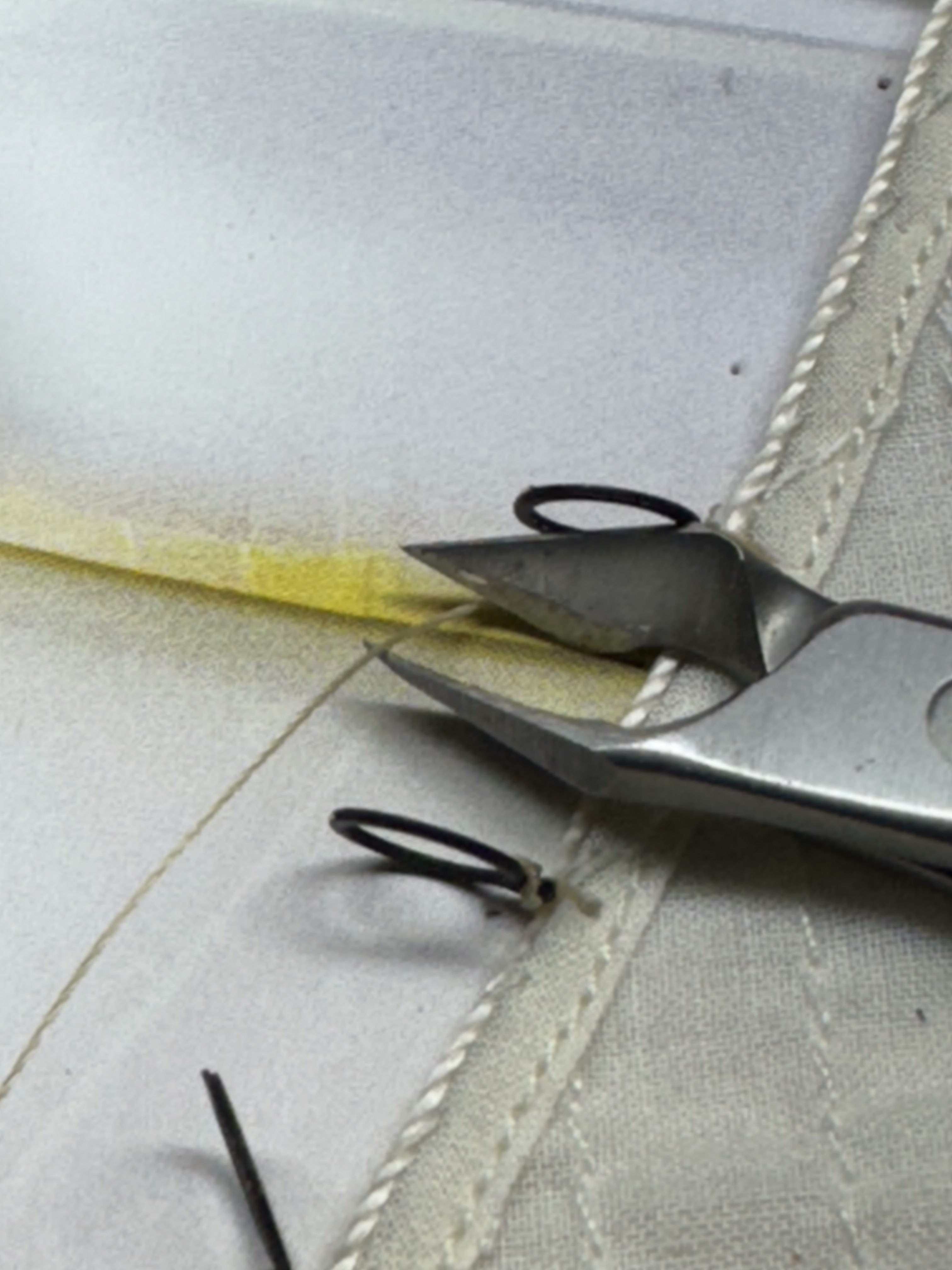
When the CA sets, cut off the excess thread - I use cuticle clippers as they are quite sharp and easy to get into tight places.

- JacquesCousteau, DB789, James H and 1 other
-
4
-
Since very few people (thanks Jacques) seem to be looking at these posts I will have to be content with they will be here in case someone else actually builds the Saucy Jack. I am building it because it will fit in the designated (by she who must be obeyed) location. I probably would not have chosen it otherwise.
So here is the jib on what will be the jib stay with all the appropriate lines/blocks attached.
I also attached the top sail to the yard using the drawings as at least the starting point.
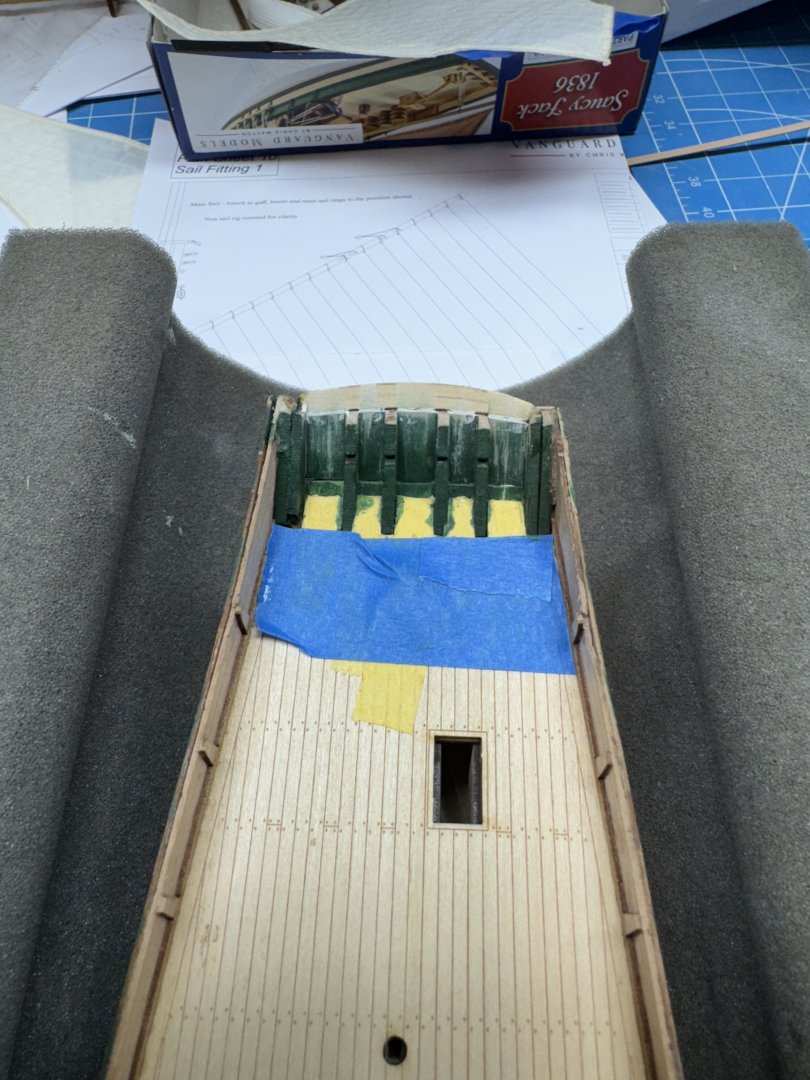
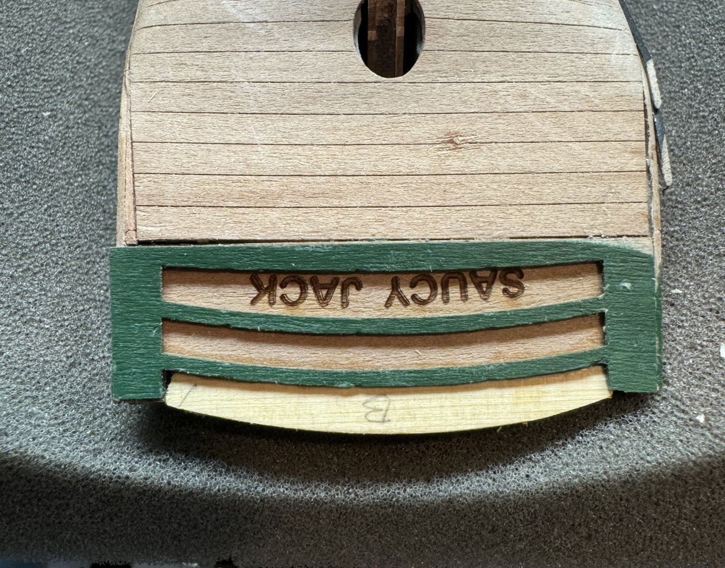
On a less cheerful not I found that I did not adequately protect the stern of the vessel while handling it during the multiple iterations of sanding an filling. The upper portion, with the openings broke off - several times actually and finally I had to perform major surgery to remove the upper section of both the inner and out transoms. I decided that since I am unlikely to be able to get all the openings properly sized and spaced i would just fill in the area and call it done. I also decided to paint the interior transom area the same green as the stripe down the side. Although it does appear I made the stripe wider than instructions show and may decide to paint the hull all the way down to the wales green.
So here is the stern repair waiting for the glue to dry and then some filler (maybe) and paint. The "B" means back as opposed to "F" for front so I did not glue it on backwards - the surgery was not completely bilaterally symmetric so the orientation matters.
- DB789, JacquesCousteau and James H
-
3
-
While waaiting around for paint to dry and other "lulls" in activity I started to look at the sails.
I purchased the "premium" sail set from Vanguard and they are a good deal more "finished" than the ones supplied with the kit.
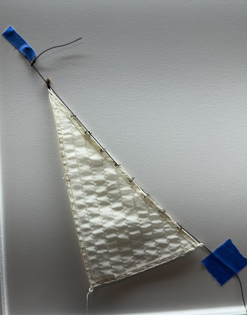
I started with the jib. Looking at the drawing (Sheet Plan 11) it is not easy (for me) to understand how the jib is attached to the jib stay except that it occurs at nine places (corners excepted) at the junctions between the several panels of material that make up the jib.
I have sailed on a sailboat (mostly much smaller than the Saucy Jack) and the jib in those cases is attached to the fore stay with "hanks" which can be anything from spring loaded clips (on very small boats) to quite complex metal devices.
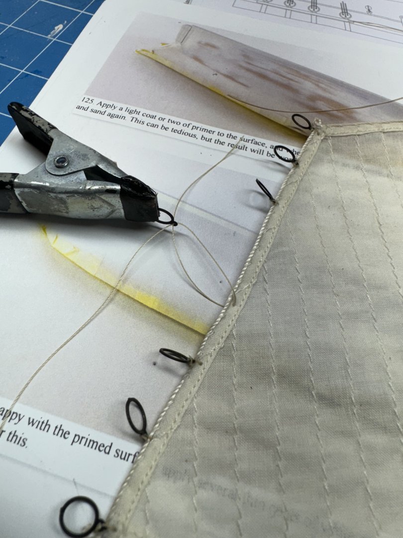
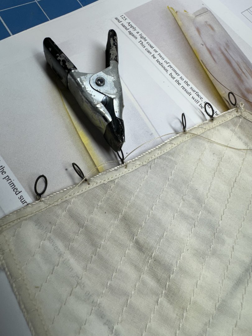
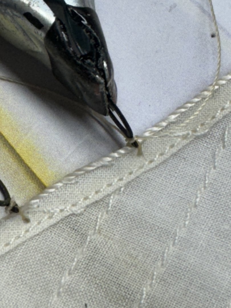
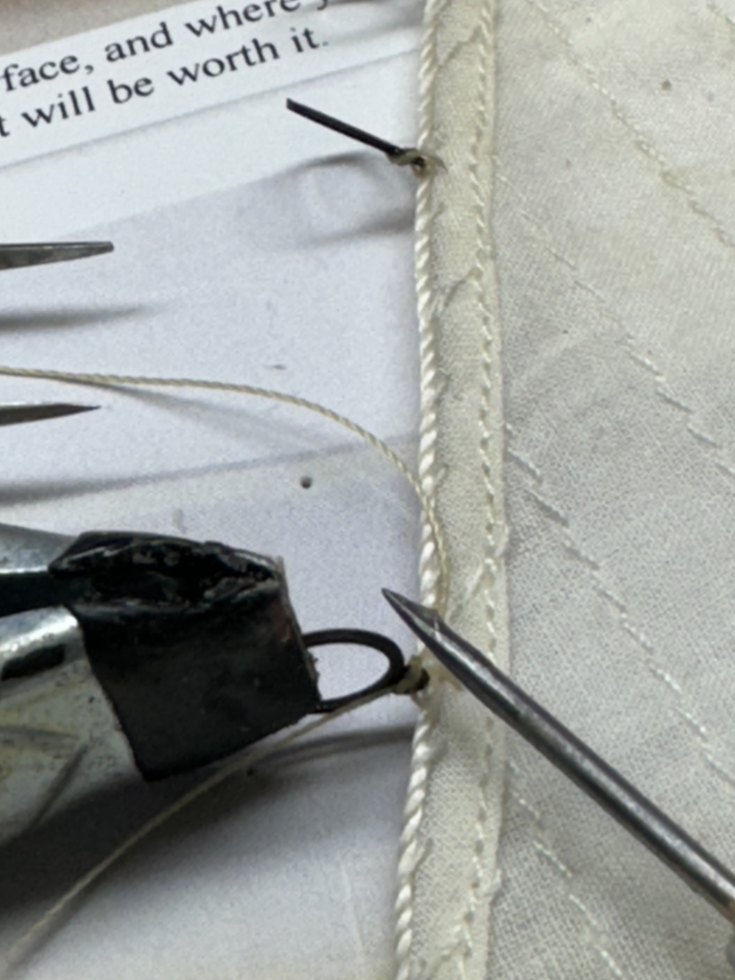
For Saucy Jack I opted for the simplest (for me) implementation of a hank using 28 gauge annealed steel wire.
I started by punching a hole in the jib at the edge using a sharp awl. Then I treaded a piece of 28 ga wire though the hole.
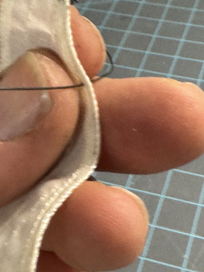
Next I used the smooth end of a #40 drill bit and wrapped the wire around the bit with the two ends crossing on top on each other.
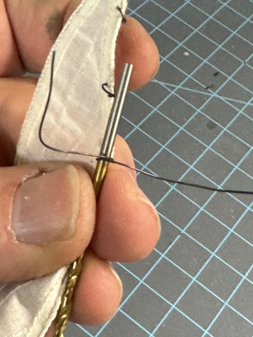
I removed the drill bit and used a pair of lineman's pliers to squeeze the two wires together where they cross and cut the ends off close to the crossing point.

I carefully put a drop of medium CA on the junction and held on for a minute or so for the CA to set.
To "fly" the sail I will route the jib stay through the wire loops before terminating it at the bow and attaching the halyard and associated tackle.
But there will be a bit in the future as I still have to figure out the other sails as well as finish the hull.
-
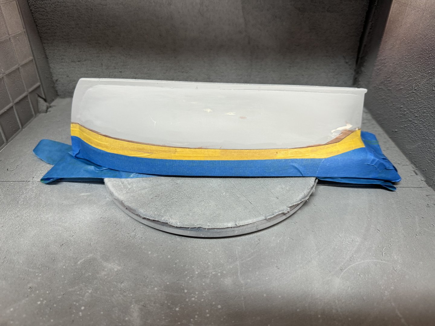
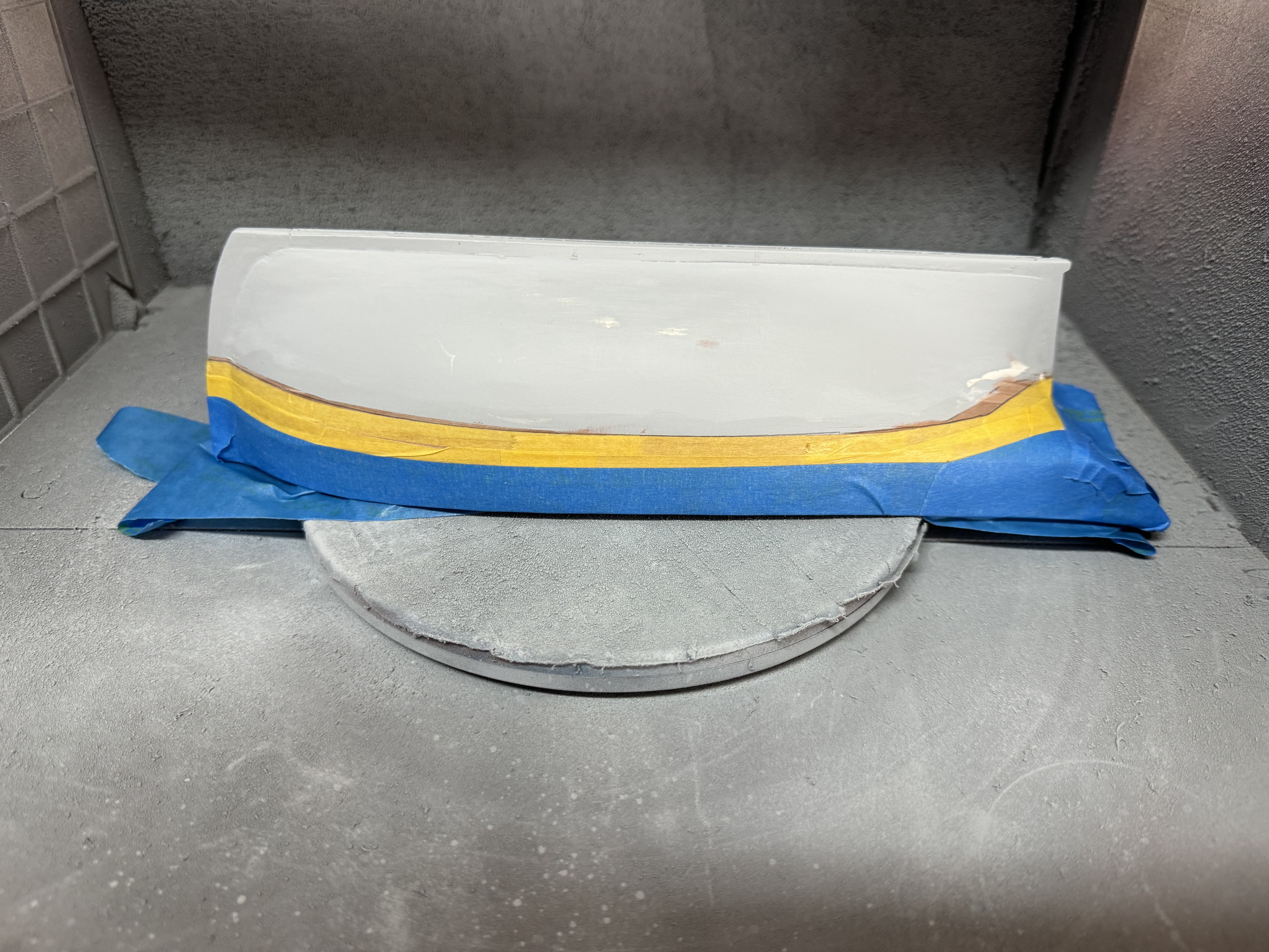
I remasked the waterline. It turned out about 1mm above where the filler ended most places.
I will start the flat white in the morning. I painted the hull/tape junction with Tamiya XF-86 Flat Clear as I have heard that this helps to seal the junction and further reduces the prospect of the spray getting under the tape. I thought about using the Tru-Color flat clear I had left over from something else but I wanted a water based product so I ordered the Tamiya from Hobbylinc.
-
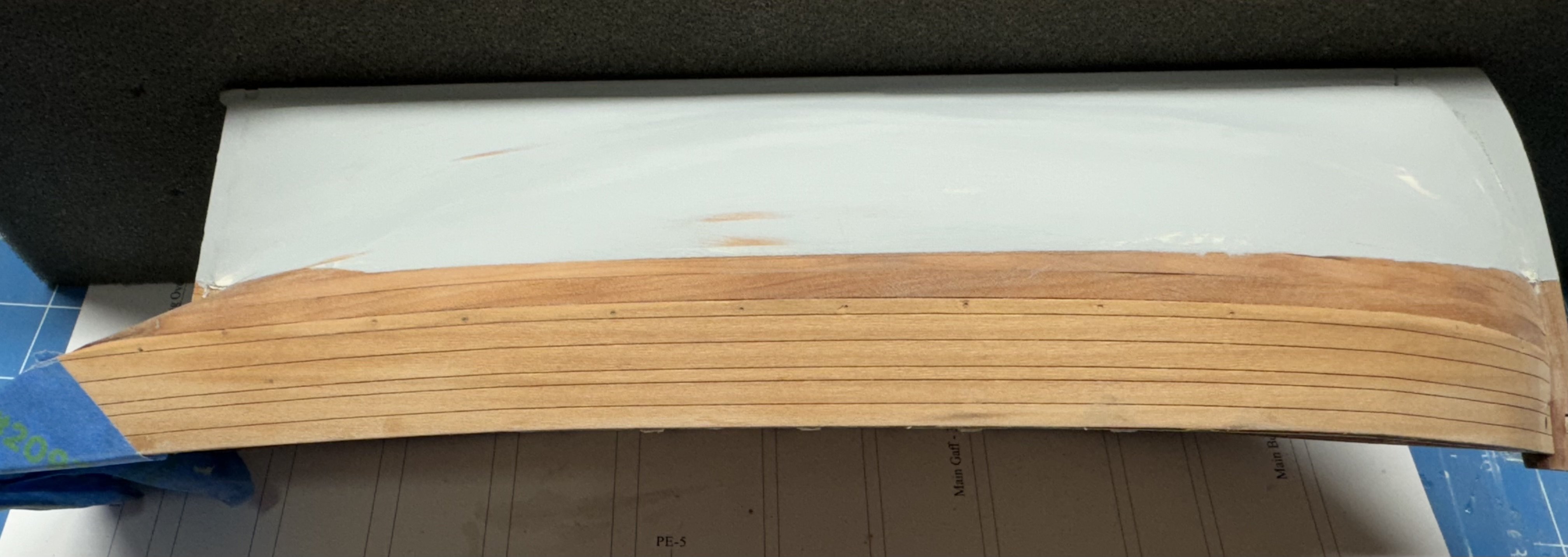
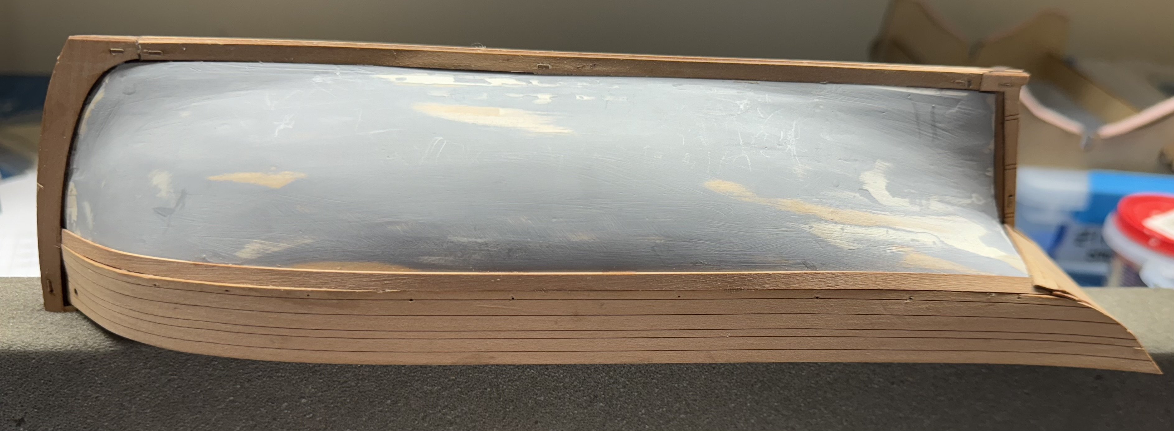
After three trips to the paint booth with filling and sanding in between I think I have the hull ready for the "final" waterline marking and then painting the below waterline portion flat white.
Before doing the "real" waterline I carefully (I think) sanded down any ridge on paint/filler that developed while doing the fill/paint/sand routine.
Here is the hull before I mark the waterline.

-
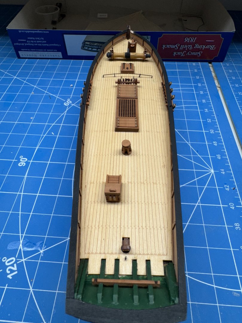
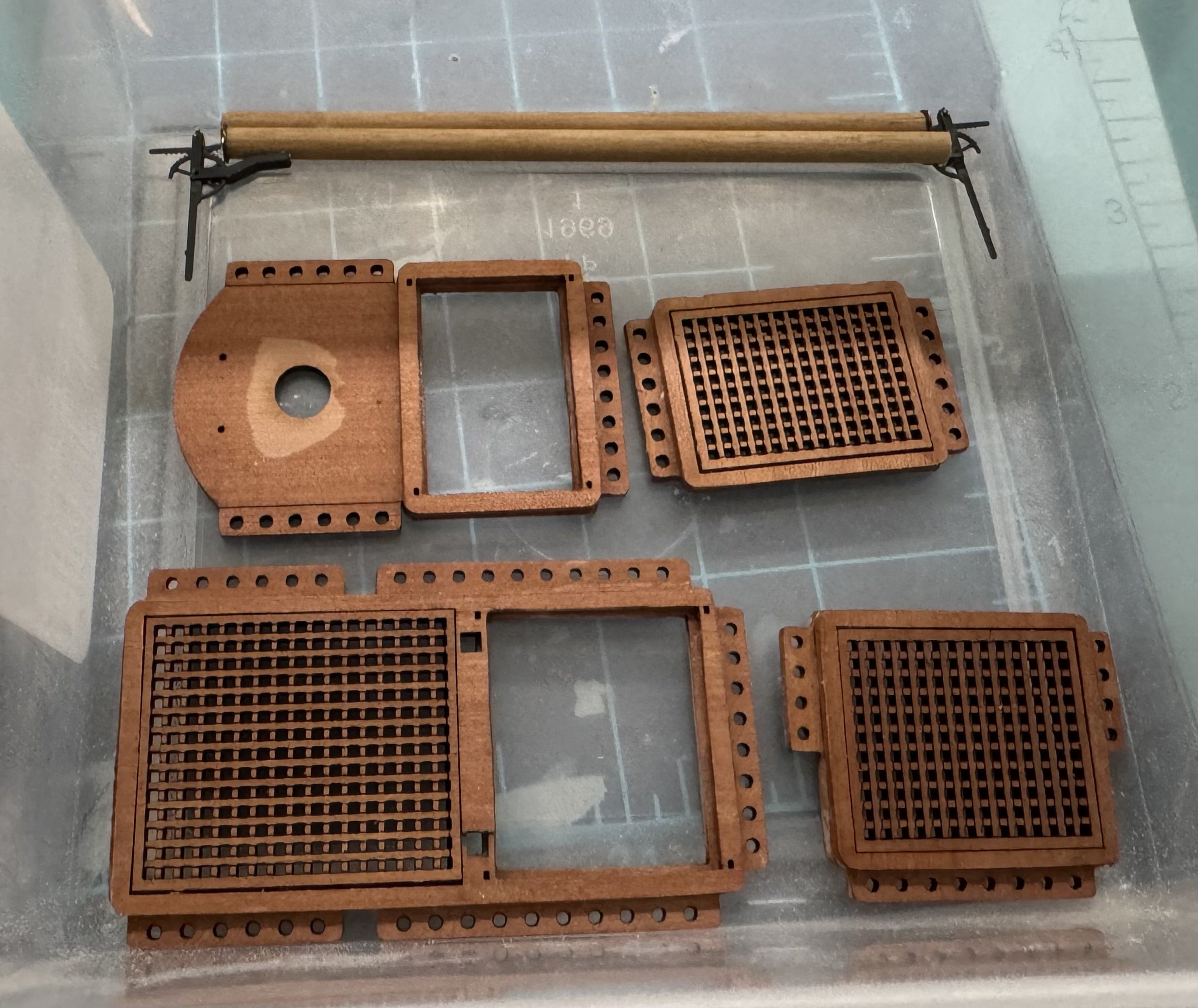
Pumps and gun deck hatch coamings and gratings ready for eventual installation.
Will probably add another coat of WoP before (or maybe after) installation

- mugje, rcweir, chris watton and 1 other
-
4
-
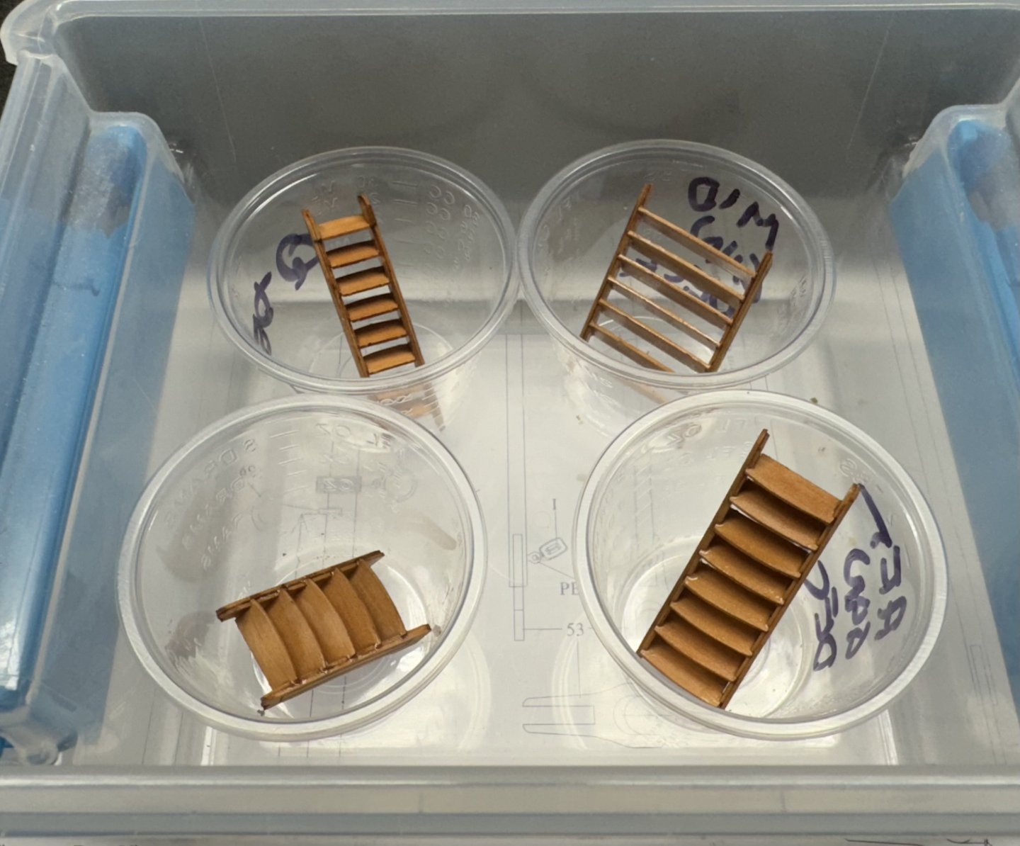
The four ladders assembled and varnished. They are in their own "to be installed later" box and identified per the carrier sheets IDs.
These were easier to assemble than some I have had occasion to build. I think principally because the slots for the steps are cut completely through the side. Others just burned an indented slot in the side and getting the steps to line up with and stick to that slot was not all that easy. These went together quickly and I use medium CA to glue in the steps as the outboard sides, with any glue mess is covered by the engraved ladder sides.
- chris watton, KurtH and mugje
-
3
-
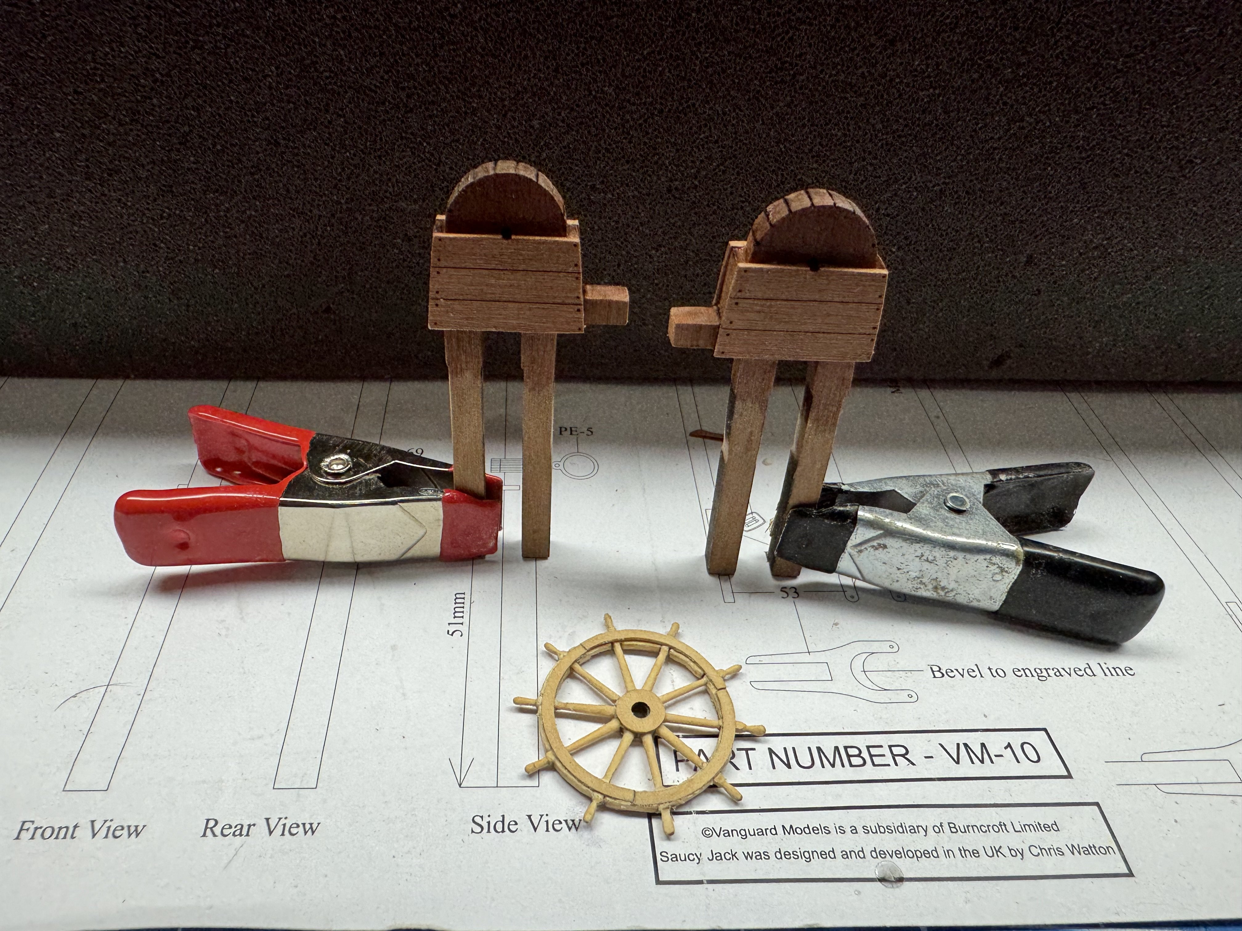
Proceeding apace I got the chain pumps assembled and varnished.
I also built a Syren 1.25" ship's wheel from the mini-kit. It is a little larger (by about 3mm) then the brass one in the Sphinx kit. I will assemble the brass one later and decide which to use. Syren also makes a 15/16" wheel kit but I think that would be too small.
Here are the pumps and the wheel.
I think I may move on to the stairs next. I always seem to have a problem getting them together. Mine never seem to go together as "smoothly" as the instructions would indicate.

-
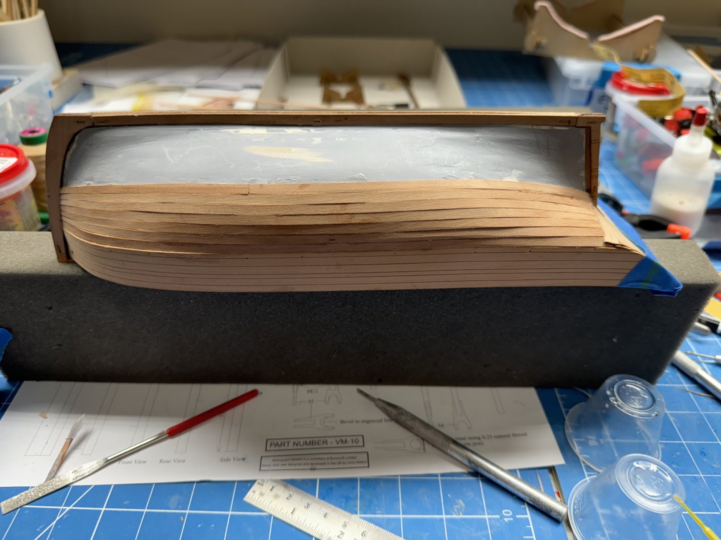
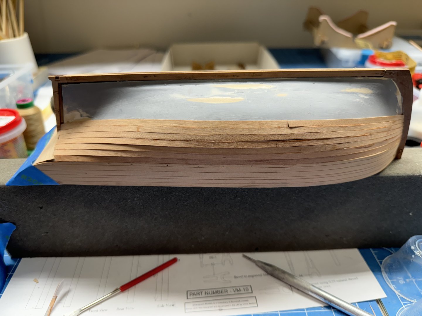
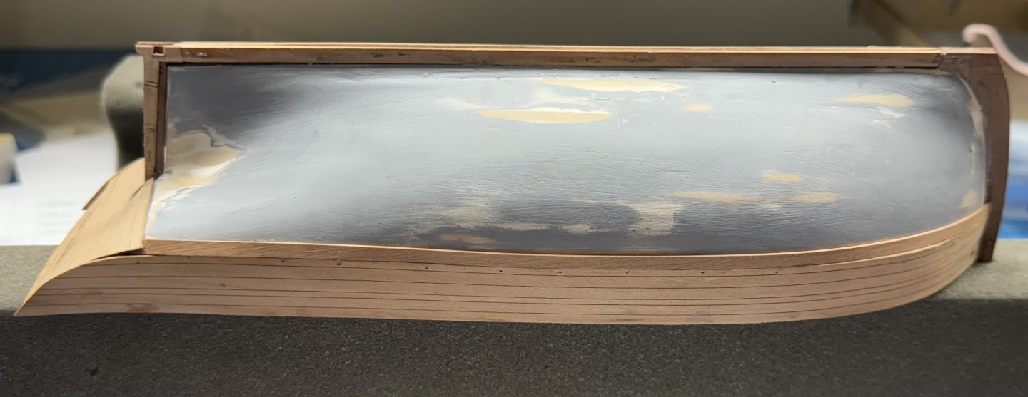
Both sides planked to the transition to stern post.
I used full length planks until the last one since the fit is kinda critical at each end.
Moving to garboard plank now then work up toward what is already done until that proves unworkable which may be sooner than I might hope.
-
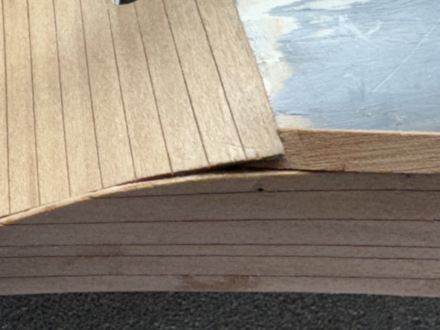
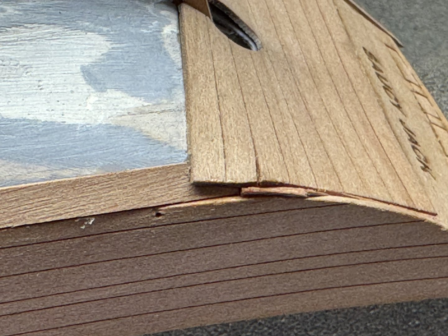
At last - the outer bulwarks and first row of the second layer are done.
I am using "medium CA" to glue the planks down - instructions say "gel" but my "thick CA" is really thick and says it is "gap-filling" which is not some thing that would be helpful if the CA fills a gap that needs to be occupied by a plank in the next row.

The transition from the transom to the side planking did not go as well as I had hoped. I cut some small "filler" pieces and jammed them into the openings then had to modify the ends of the first row of planks to fit into the remaining opening. I am not sure how this is going to look after a bit of sanding but it will have to do as I am fresh out of ideas to make this area look better. At least it is somewhat consistent from side to side.


Saucy Jack by cdrusn89 - Vanguard Models - 1/64th
in - Kit build logs for subjects built from 1801 - 1850
Posted
Here is the bowsprit and associated rigging.
Mast head with jib halyards and throat and peak halyards.
(I twisted the upper throat block some to get it to line up better with the lower after i saw this picture)
The top mast with top sail yard.
And a view down the starboard side looking forward.
I have a few more rope coils to make and when I get them installed and do a little touch-up painting (and take the rest of the blue tape off) I will be ready to build the clear display stand and "put it on the shelf".